2X660MW SUPER CRITICAL THERMAL POWER PLANT AT THARANGAMBADINAGAPATTINAM DIST.TAMIL NADU CONSULTANT DEVELOPMENT CONSULTANTS PRIVATE LIMITED 191, ANNA SALAI, CHENNAI ‐ 600006 BID SPECIFICATION NO. : 11Z02SPCG001 MAIN PLANT PACKAGE [BOILER TURBINE GENERATOR] VOLUME : II A LEAD SPECIFICATION
Transcript
2X660MW SUPER CRITICAL THERMAL POWER PLANT AT
THARANGAMBADINAGAPATTINAM DIST.TAMIL NADU
CONSULTANT
DEVELOPMENT CONSULTANTS PRIVATE LIMITED 191, ANNA SALAI, CHENNAI ‐ 600006
CPCPL-Super Critical TPP-Tharangambadi [2 x 660 MW] Main Plant Package CONTENTS DCPL-11Z02
VVOOLLUUMMEE :: IIII -- AA
LLEEAADD SSPPEECCIIFFIICCAATTIIOONN
CPCPL-Super Critical TPP-Tharangambadi [2 x 660 MW] Main Plant Package CONTENTS DCPL-11Z02
CONTENTS VOLUME-IIA : LEAD SPECIFICATION SECTIONS DESCRIPTION SECTION-I : INTENT OF SPECIFICATION SECTION-II : PROJECT SYNOPSIS & GENERAL INFORMATION SECTION-III : SCOPE OF SUPPLY & SERVICES SECTION-IV : GENERAL TECHNICAL REQUIREMENTS SECTION-V : PROJECT MANAGEMENT & SITE SERVICES SECTION-VI : ENGINEERING SERVICES SECTION-VII : QUALITY ASSURANCE REQUIREMENTS SECTION-VIII : PERFORMANCE GUARANTEES & TESTS SECTION-IX : REQUIREMENT OF SPARES, TOOLS & TACKLE, LUBRICANTS/
OIL/CONSUMABLES SECTION-X : SALIENT DESIGN DATA SECTION-XI : LIST OF ACCEPTABLE VENDORS
CPCPL-Super Critical TPP-Tharangambadi [2 x 660 MW] Main Plant Package
VOL-II-A-SEC-I 1
DCPL-11Z02
VOLUME : II-A
SECTION-I
INTENT OF SPECIFICATION
CPCPL-Super Critical TPP-Tharangambadi [2 x 660 MW] Main Plant Package
VOL-II-A-SEC-I - 1
DCPL-11Z02
VOLUME : II-A
SECTION-I
INTENT OF SPECIFICATION
1.00.00 This specification is intended to cover supply and installation of Main Plant
Equipments & accessories as detailed hereinafter for 2 x 660 MW Units of Chettinad Power Corporation Pvt.Ltd. (CPCPL) at Tharangambadi.
The scope shall include design, engineering, manufacture, inspection and
testing at manufacturer's works, packing and shipment and delivery at site. In addition, the Bidder's scope shall also include erection/installation including unloading storage and handling at site, site testing, commissioning, trial run, performance and guarantee tests and other services including supply co-ordination, engineering and project management related to Main Plant Equipment Accessories specified hereinafter and in accordance with the requirements, conditions, appendices, drawings etc. stated in Volume-I and Volumes II-B to II-J which shall be considered as a part of this volume as completely as if bound herewith.
The specification consists of Volumes : I, II & III detailed index of which has
been furnished elsewhere. This specification shall be read and construed in conjunction with the drawings and annexures to determine the scope of work and terminal points. The quantities shown on drawings and annexures are indicative. Any variation arising during detailed engineering stage will be taken into account by the Contractor without any extra cost and time to the owner.
The Bidder shall be responsible for providing all material, equipment and
services, specified or otherwise which are required to meet the intent of this specification, ensuring high degree of reliability and ease of operation and maintenance. The equipment and system/sub-systems shall conform to all aspects of high standards of engineering, design and workmanship and shall be capable of performing in continuous commercial operation, in a manner acceptable to the Owner and shall also be in line with the current practice for reliable and efficient functioning of the plant.
Owner shall interpret the meaning of the specification, drawings, requirement
of operation, maintenance, redundancy etc., and shall have a right to reject or accept any work or material which in his assessments is not technically complete to meet the requirements of this specification and/or applicable National and International standards mentioned elsewhere in this specification.
Bidder is required to carefully examine and understand the specifications and seek clarifications, if required, to ensure that he has understood the specifications as intended by the Owner. In the absence of any specific clarifications made by the Owner during bidding stage, the interpretation of Owner shall be final. The Bidder's offer should not carry any sections like
CPCPL-Super Critical TPP-Tharangambadi [2 x 660 MW] Main Plant Package
VOL-II-A-SEC-I - 2
DCPL-11Z02
clarifications, interpretations and/or assumptions. All such points are required to be clarified during bidding stage.
In the event of conflict between requirements of any two clauses of this
specification/documents or requirements of different codes/standards, specified, the more stringent requirement as per the interpretation of the Owner shall apply.
The Bidder may also make alternate offer, provided such offers are superior
in his opinion, in which case, adequate technical information and justifications, operating feed back data etc. shall be enclosed with the offer, to enable the Owner to assess the superiority and reliability of the alternative offered without the need to seek any further clarification or explanation. In case of each alternative offer, its implications on the performance, guaranteed efficiency, auxiliary power consumptions and definite advantages the Owner can positively derive shall all be clearly brought out along with commercial implications, if any for the Owner to make an overall assessment. In any case, the base offer shall necessarily be in line with this specification. Under no circumstances shall the specified equipment/plant be brought out as an alternative offer.
In case all the above requirements are not complied with, the offer may be
considered as incomplete and liable to be treated as non-responsive. 2.00.00 Whenever a material or article is specified or described by the name of a
particular brand, manufacturer or vendor, the specific items mentioned shall be understood as establishing type, function and quality desired.
3.00.00 In case there is any difference of content/ information between ‘”Hard Copy”
and “Soft Copy” of this specification document, the statement/ information as printed in hard copy shall prevail.
VOLUME : II-A
SECTION-II
PROJECT SYNOPSIS AND GENERAL INFORMATION
CPCPL-Super Critical TPP-Tharangambadi [2 x 660 MW] Main Plant Package CONTENTS DCPL-11Z02
CONTENT CLAUSE NO. DESCRIPTION PAGE NO. 1.00.00 INTRODUCTION V.IIA/S-II : 1 2.00.00 APPROACH TO SITE V.IIA/S-II : 1 3.00.00 LAND V.IIA/S-II : 1 4.00.00 SOURCE OF COAL V.IIA/S-II : 2 5.00.00 SOURCE OF WATER V.IIA/S-II : 2 6.00.00 ASH DISPOSAL AREA V.IIA/S-II : 2 7.00.00 SALIENT DESIGN DATA V.IIA/S-II : 2
CPCPL-Super Critical TPP-Tharangambadi [2 x 660 MW] Main Plant Package
VOL-II-A-SEC-II - 1
DCPL-11Z02
VOLUME : II-A
SECTION-II
PROJECT SYNOPSIS AND GENERAL INFORMATION 1.00.00 INTRODUCTION M/s Chettinad Power Corporation Pvt. Ltd. (CPCPL), a company promoted by
M/s Chettinad group of companies (www.chettinad.com), Chennai is setting-up a Merchant Power Plant with the capacity of 2x660MW Super Critical units in Tharangambadi in Nagapattinam District, Tamil Nadu.
The Bidder shall acquaint himself by a visit to the site, if felt necessary, to
understand the conditions prevailing at site before submission of the bid. The information given here in under is for general guidance and shall not be contractually binding on the Owner. All relevant site data /information as may be necessary shall have to be obtained /collected by the Bidder.
2.00.00 APPROACH TO SITE The District head quarters of Nagapattinam is at a distance of about 25km on
south side of site for proposed project and the state capital-Chennai is at about 325km on north side. The power plant site is located in between the National Highway 45A connecting Thirkkadaiyur and Karaikal.
The nearest airport is located at Thiruchirapalli, which is 160Kms from site
and the nearest seaport is Karaikal, which is less than 10Kms. The contractor shall assess the existing rail/ road infrastructure and shall be
solely responsible for transporting equipment and material to site. The material consignments shall be as per the restrictions of rail and road transportation prevailing in the country.
3.00.00 LAND
About 821 acres of land has been identified for the project. The land is located at villages of Kaliyappanallur, Sattankudi, Erukkattancherri, Manikkappangu in the Taluk of Tharangambadi in Nagapattinam District in State-Tamil Nadu. The site for the proposed power project is in Coastal region located at about 3-4 kms from Thirukkadaiyur coast near Tharangambadi in South Eastern part of Tamil Nadu state. The land features show that a dyke protects the plot from inundation during high tide. BTG land area will be raised to above the high flood level and same will be decided during detailing engineering stage. A preliminary plot plan is attached along with the tender specification. Bidders to generally confirm their proposals to this plot plan. Bidders are required to submit, along with their offer specific plot plan proposals with any suggestion modifications. The plot plan will be discussed during tender evaluation stage.
CPCPL-Super Critical TPP-Tharangambadi [2 x 660 MW] Main Plant Package
VOL-II-A-SEC-II - 2
DCPL-11Z02
4.00.00 SOURCE OF COAL
It is proposed to import coal from Indonesia. CPCPL is also trying to get coal linkage for the project (for Indian coal)
5.00.00 SOURCE OF WATER
The entire plant water requirements will be met from the seawater. The estimated seawater requirement for the proposed power plant is furnished below.
PARTICULARS m3/h
CT Make-up water, Feed water for Desalination plant & Electro chlorination plant
12527
Total 12527
6.00.00 ASH DISPOSAL AREA
Ash will be transported to ash pond in the land identified near the plant. Ash slurry will be dumped into the disposal area would be contained in the ash pond by constructing bunds around the periphery of the disposal area. The required area of the land will be about 65 acres by the consideration 100% bottom ash disposal to pond for 7 years. The ash pond will be lined with impervious lining such as HDPE sheets, which will provide a perfect lining for the ash ponds. The HDPE geo-membrane has a lower tendency to exchange ions with leachate constituents and maintains its integrity as a barrier over a long period of time. It may be noted that HDPE lining is widely used in power plants, copper/zinc smelters etc.
7.00.00 SALIENT DESIGN DATA 7.01.00 Meteorological data of site is given below:-
Latitude : 11.03’ 0026” N Longitude : 79.51’ 0260” E
Atmospheric Conditions : Hot, humid and corrosive, close to Sea front (Tropical)
Seismic Data : As per IS:1893-latest
Zone : Zone II
Intensity : As per IS:1893-Latest
Meteorological Data
Ambient Air Temperature
Maximum Dry Bulb Temperature : 41°C
CPCPL-Super Critical TPP-Tharangambadi [2 x 660 MW] Main Plant Package
VOL-II-A-SEC-II - 3
DCPL-11Z02
Minimum Dry Bulb Temperature : 16.8°C
Design Dry Bulb Temperature ( for design of cooling tower)
: 32°C
Design wet Bulb Temperature ( for design of cooling tower)
: 28°C
Relative Humidity
Mean Maximum Humidity (Summer) : 75%
Mean Minimum Humidity (Summer) : 60%
Maximum Humidity (Monsoon) : 80%
Minimum Humidity (Monsoon : 65%
Wind Velocity : As per IS:875
Rainfall
Annual Rainfall (Maximum) : 1403 mm
Annual Rainfall (Minimum) : 450.5 mm Twenty four (24) hour : 481 mm
VOLUME : II-A
SECTION-III
SCOPE OF SUPPLY AND SERVICES
CPCPL-Super Critical TPP-Tharangambadi [2 x 660 MW] Main Plant Package CONTENTS DCPL-11Z02
CONTENT A. SUPPLY OF EQUIPMENT AND SYSTEMS B. SERVICES TO BE RENDERED BY THE BIDDER C. EXCLUSIONS D. TERMINAL POINTS E. FACILITIES TO BE PROVIDED BY THE OWNER
CPCPL-Super Critical TPP-Tharangambadi [2 x 660 MW] Main Plant Package
VOL-II-A-SEC-III - 1
DCPL-11Z02
VOLUME : II-A
SECTION-III
SCOPE OF SUPPLY AND SERVICES
A. SUPPLY OF EQUIPMENT AND SYSTEMS The Works of this Package (Steam generator, Turbine generator, Power cycle
piping, auxiliaries and accessories for 2 x 660 MW Units of Chettinad Power Company Pvt.Ltd. shall be contracted on a single package basis as detailed hereunder.
1.00.00 Two(2) nos. super-critical once through dry bottom, balanced draft, semi-
outdoor type pulverized coal fired with oil as start-up and stabilising fuel steam generating units, each complete with all major auxiliary plant and equipment consisting of, but not limited to, the following :
a) Furnace / evaporator complete with vertical water walls, headers,
steam generating tubes,risers,furnace bottom hoppers etc for once through boiler.
b) Low NOx Burner. c) Economiser, Superheater, Reheater, Separator other Pressure Parts,
Soot Blowing System etc including circulation pumps(for low load and start up).
d) Integral pipework, valves and specialties along with supporting
system. e) Draft plant including ID, FD & PA Fans, Tri-sector type air-preheaters,
ducting and accessories upto chimney inlet flange. f) Boiler pent house with cooling arrangement and adequate dust
extraction system for Ash free/clean area in pent house. g) Raw coal bunker, Raw coal bunker outlet gates and raw coal piping
and feeders h) Permanent facility for bunker emptying chute to enable unloading of
bunkers on trucks at ground level. i) Fuel (Coal) preparation and firing systems including coal pulverizers,
start-up/ stabilisation system with fuel oil and mill rejects handling & disposal system.
j) Integral instrumentation, safety interlocks and controls for steam
generator. k) Galleries, platforms and structural steelwork.
CPCPL-Super Critical TPP-Tharangambadi [2 x 660 MW] Main Plant Package
VOL-II-A-SEC-III - 2
DCPL-11Z02
l) Electrostatic precipitators. m) LP Dosing and Oxygenated treatment. n) Thermal Insulation and acoustic insulation to minimize noise pollution. For detailed scope, refer to Volume: IIB of this specification. 2.00.00 Auxiliary boiler for this project is not envisaged. However, if the standard
practice of the bidder requires a Auxiliary boiler for the purpose of commissioning, start ups, then the same is to be supplied and details of the same may be furnished along with the proposal.
3.00.00 Fuel Oil/Light Diesel Oil pressurizing and heating System as detailed in
Volume: II-B of this specification. 4.00.00 Two (2) nos. Turbine Generator. The Turbine Generator configuration shall
be as per Manufactures standards, each complete with all related auxiliaries matching super critical boiler parameters and consisting of, but not limited to, the following major sub-systems:
a) Steam turbine proper along with auxiliary systems e.g. gland sealing,
turbine lube oil and control oil system for lubrication protection-governing, water spray, steam washing systems etc. as applicable.
b) Stop and control valves on Main Steam (MS) and Hot Reheat (HR)
inlet with strainers, quick closing non-return valves on extraction lines and Cold Reheat (CR) outlet, H.P.& L.P. Bypass valves etc. together with hydraulic actuation system, reheater isolating device, blanking pieces etc. as necessary for protection during steam blowing.
c) All integral piping for turbine steam, drain and vent systems including
flash boxes, oil, air and water systems. d) Condensate Polishing System. e) Generator coupled to steam turbines and complete with auxiliary
systems e.g. excitation, seal oil, hydrogen cooling, stator cooling, carbon-di-oxide purging systems etc. as necessary.
f) Integral instrumentation, safety interlocks and controls for the
turbo-generator. g) Thermal Insulation and acoustic insulation. For detailed Scope, refer to Volume : II-C of this specification. 5.00.00 Water cooled double pass surface condensers for each unit (along with
companion flanges) complete with integral accessories, water box handling devices, air evacuation, on load tube cleaning system (OLTC) etc. as specified in Volume: IIC of this specification.
CPCPL-Super Critical TPP-Tharangambadi [2 x 660 MW] Main Plant Package
VOL-II-A-SEC-III - 3
DCPL-11Z02
6.00.00 All power cycle pumps and drives as required for each unit including Boiler Feed Pumps, Condensate Extraction Pumps, Heater Drain Pumps (if applicable); the pumps are to be complete with accessories for sealing and lubrication, flexible/hydraulic couplings, gear box, integral instrumentation, handling devices, etc.
7.00.00 Low pressure and high pressure feed heaters and deaerator for each unit
complete with integral instrumentation and valves, supports, platforms, rails, handling devices etc. as specified in Volume: IIC of this specification.
8.00.00 Turbine oil purification system for each unit and central turbine oil storage and
transfer system common for the units as specified in Volume: II-C of this specification.
9.00.00 Complete piping, valves and specialties for each of the units and common
systems comprising, but not limited to, the following: a) Power cycle piping consisting of main steam, hot reheat, cold reheat,
extractions, auxiliary steam, air evacuation, cascade drains, condensate, feed water, cycle make-up, drains to waste and atmospheric vents etc. Blanking devices for emergency stop and reheat stop valves and other items as required for steam blowing operation along with steam blowing piping and quick opening valve as specified in Volume: IID of this specification.
b) Low pressure piping for various water (cooling, service, drinking, plant
make-up etc.),, steam (other than that covered in item [a] above) and other services required for BTG would be supplied by the BTG vendor at the terminal point near BTG area . as detailed in Volume: II-D of this specification.
10.00.00 Over Head Lube Oil Tank, Expansion Tanks etc., to be constructed under this
specification, waste drain and other tanks not specifically mentioned but required for completion of various systems supplied under this specification. Refer Volume: II-D of this specification for detailed scope.
11.00.00 Blow down systems. 12.00.00 Thermal insulation including cladding material as required for conservation of
heat and for personnel protection for both the units, as specified in Volume: II-D of this specification.
13.00.00 Complete control & instrumentation (C&I) systems required for each unit and
common system shall comprise of but not be limited to the following. Any item not specifically mentioned herein but required for completion of the total C&I system shall be included. Refer specification Vol. IIE for further detail.
a) Distributed Digital Control & Management Information System
(DDCMIS) for control, monitoring, data acquisition, alarm and sequence of events recording for each unit.
b) GPS Master clock system
c) Large video screens
CPCPL-Super Critical TPP-Tharangambadi [2 x 660 MW] Main Plant Package
VOL-II-A-SEC-III - 4
DCPL-11Z02
d) Performance calculation
e) Plant Performance Analysis, Diagnostic and Optimization (PADO) system
f) Complete SG & auxiliaries integral control & instrumentation including BMS, MFT and Acoustic type Boiler Flue Gas Temperature measurement.
g) Complete TG & auxiliaries’ integral control & instrumentation including EHG and TG protection.
h) CCTV system for plant & equipment surveillance
i) Furnace flame monitoring/T.V
j) Computerized maintenance & inventory management system
k) Plant wide data network
l) On line rotating machine condition monitoring system
m) Optical fiber interface between DDCMIS and PLC /microprocessor based control in BOP area.
n) Electrical Power supply system including UPS.
o) Control panel, Desk, Junction box and Termination & Relay cabinets.
p) Steam Water Analysis and Sampling System
q) Flue gas analyzers for control & monitoring
r) Flue Gas Emission Monitoring Instruments
s) Control valves and dampers with actuators and accessories
t) Flow elements with root valves and accessories
u) Field instruments including transmitters, switches, temperature elements and gauges
v) Instrumentation signal & control cable, extension & compensating cable, special cable and optical fiber cables
w) Instrument racks and enclosures
x) Erection hardware for instrument process hook .
y) Erection hardware for the pneumatic hook up .
z) Cable erection accessories
CPCPL-Super Critical TPP-Tharangambadi [2 x 660 MW] Main Plant Package
VOL-II-A-SEC-III - 5
DCPL-11Z02
14.00.00 Complete cooling water system for two units consisting of, but not limited to, the following major equipment :
a) Auxiliary Cooling Water (ACW) pumps, drives and accessories.
b) Closed circuit DM cooling water pumps, drives and accessories.
c) Heat exchangers for closed circuit DM cooling water systems.
d) Cycle make-up pump & Boiler fill pump For detailed scope, refer to Volume: II-H of this specification. 15.00.00 . 16.00.00 Bidder to provide necessary slings/attachments required for lifting of Turbine
components (EOT crane is not in BTG scope) 17.00.00 Elevators complete with drives, electricals, control and instrumentation and all
other accessories, inclusive of, but not limited to the following facilities in the Main Plant Package.
a) Steam Generator and Mill area. 18.00.00 Flue gas desulphurization system 19.00.00 Complete electrical equipment and accessories for the units which shall
include but not be limited to the following :
a) All major transformers e.g., Generator & Station transformers, Unit Transformer, Unit &Station auxiliary transformers
b) All LT distribution transformers. c) Neutral grounding resistors for Unit and Station transformers
d) HT & LT switchgears, motor control centers, distribution boards, ABT
panels, control & protection panels etc within Power house. e) Generator bus ducts, HT phase segregated bus ducts & LT bus ducts.
f) Batteries, battery chargers, uninterrupted power supply (UPS) system and DC distribution system.
g) AC and DC motors and motor actuators h) HV,LV power and control cables
i) Complete grounding (Under ground and over ground) and lightning
protection system with in BTG area.
CPCPL-Super Critical TPP-Tharangambadi [2 x 660 MW] Main Plant Package
VOL-II-A-SEC-III - 6
DCPL-11Z02
i) Complete electrical system for ESP, Boiler and Turbine j) Complete cabling including supply of cables, cable trays/racks
interconnecting various equipment supplied under the package and interfacing with other plant facilities as specified.
For Complete details refer to Volume: II-F of this specification. 20.00.00 Civil & Structural Works The services shall include but not be limited to the following : a) Foundation details for all the equipment supplied under this package
including installation of anchor bolts, sleeves and embedded fixtures. Foundation of BF pumps, ID fans, FD fans, PA Fans, Coal Mills and Turbo-generator shall be mounted on springs/dampers. All static and dynamic loading reaction on the equipment foundation to be furnished for civil design.
b) Fabrication & erection of all types of steel work as required for Boiler/
Mill buildings, platforms, stairs, ladders, hangers & supports etc.
c) Pipe and Cable Racks within BTG scope.
d) Minor chipping and grouting. 21.00.00 One set of spares for all plants and equipment for all systems, as
recommended by the respective manufacturer/bidder for regular reliable operation of minimum three (3) years (for indigenous supply) and five (5) for imported spares. Bidder is to develop recommended list of spare parts with prices by items and this shall be furnished separately in the prescribed format. Sufficient description and drawings are to be provided to permit analysis and evaluation of spares recommended.
One set of tools and tackle, fixtures etc. in new condition, as required for
regular operation and maintenance of the plant and equipment offered. Adequate means shall be provided for lifting and handling of each item of plant and equipment including slings etc. Price for such tools & tackle, fixtures etc. shall be furnished separately in the prescribed format.
22.00.00 Any other accessories as required to meet the system completeness with in
the BTG Terminal point. B. SERVICES TO BE RENDERED BY THE BIDDER The services to be rendered by the Bidder shall include but not be limited to
the following : 1.00.00 Services for complete engineering, co-ordination and project management as
detailed in Section-IV of this specification volume. 2.00.00 Services for shop tests and quality assurance, etc. as detailed elsewhere in
this specification.
CPCPL-Super Critical TPP-Tharangambadi [2 x 660 MW] Main Plant Package
VOL-II-A-SEC-III - 7
DCPL-11Z02
3.00.00 Services for construction, fabrication, equipment erection, testing as well as trial run & commissioning of various equipment and accessories under the contract. The details of such services are indicated in Section-VI of this specification volume. The successful bidder shall arrange for two nos. 400 Tonnes capacity tower cranes, one number each 660 MW unit for speedy erection activities, if required requirement and capacity of any additional cranes will be studied by contractor and adequate capacity cranes shall be deployed to meet the project schedule. Moreover, all erection tools and tackles necessary for generator stator handling and erection shall be arranged by the bidder.
4.00.00 Vendor to indicate maximum weight of component to be lifted (excluding
stator) for sizing the TG Hall EOT crane (EOT crane is not in BTG scope). Stator to be lifted by strand jack method.
5.00.00 Supply of all mandatory, erection/commissioning and recommended spares,
special tools & tackle including required after-sales services during and after the warranty period.
6.00.00 Supply of all consumables required for the works as per provision of
respective clauses specified in conditions of contract. 7.00.00 Furnishing of all document, drawings, design basis reports, optimization,
study reports, instruction manuals, etc. including "As built" drawings, as called for in the specification both in requisite no. of hard copies and in soft form (CD).
8.00.00 Operation and Maintenance training. 9.00.00 Obtaining approval from statutory bodies in India. However, Purchaser shall
provide assistance to do so. 10.00.00 Equipment shop painting & Final painting at site. 11.00.00 Any other service, although not specifically called for but required for a
turn-key contract of the size and nature indicated in this specification. 12.00.00 For details of services under clause B, subsequent sections of this Lead
specification may be referred. C. EXCLUSIONS The following items are excluded from this contract : 1.00.00 Complete coal handling plant (CHP) for the power plant. However, all
structural and civil works in Mill bay except the technological structure required for bunker conveyors are included in bidder's scope. The bidder shall consider in design and provide necessary embedded plates, inserts, openings etc. in Mill bay for installation of bunker conveyors, dust extraction equipment, associated accessories and electrical to be provided by coal handling system Contractor.
2.00.00 Complete plant water system (PWS). For various quality of water required by
the bidder, e.g. Sea water, desalinated water, demineralised water, drinking
CPCPL-Super Critical TPP-Tharangambadi [2 x 660 MW] Main Plant Package
VOL-II-A-SEC-III - 8
DCPL-11Z02
water etc., for the main plant package, the Bidder shall indicate one terminal point for each category at a location indicated in specification. The Owner shall provide water at required flow rate and pressure at these points.
3.00.00 Cooling Tower. 4.00.00 Condenser cooling water system. 5.00.00 Ash Handling Plant. 6.00.00 Compressed Air system (Plant and Instrument Air system) 7.00.00 Fire Protection System 8.00.00 Air Conditioning and Ventilation system 9.00.00 CT Blow down 10.00.00 Sump pumps, TG hall EOT , CW Pump EOT , Miscellaneous cranes & Hoists,
Elevaters ( except Boiler elevator) and Chemical laboratory equipments 11.00.00 H2, CO2 and N2 Cylinders. 12.00.00 Workshop equipment. 13.00.00 Hydrogen Generation Plant. 14.00.00 Chimney. 15.00.00 Power evacuation and transmission system beyond Generator Transformers
and station Transformers H V Bushing. Necessary coordination with Transmission package supplier shall be the responsibility of the bidder under this contract.
16.00.00 Internal roads and surface drains within coal handling and Ash handling plant
and plant water system areas. Arterial roads and drains in above mentioned areas as well as other roads and drains as specified elsewhere in this specification shall, however, be included in the scope of the Bidder. Coordination for matching roads and drains under exclusion with that supplied under this contract shall be the responsibility of the Bidder.
17.00.00 Entire illumination system. 18.00.00 Pipe and cable racks beyond the terminals specified elsewhere in this
specification. Necessary coordination with Coal Handling Plant and Plant Water System package vendor for interface engineering and construction shall be the responsibility of the Bidder.
19.00.00 Supply of utilities and electric power beyond the terminals specified
elsewhere in this specification for Coal Handling and Ash Handling Plants and Plant Water System Package. Necessary coordination with Coal Handling Plant and Plant Water System package vendor for interface engineering and construction shall be the responsibility of the Bidder.
CPCPL-Super Critical TPP-Tharangambadi [2 x 660 MW] Main Plant Package
VOL-II-A-SEC-III - 9
DCPL-11Z02
20.00.00 Civil Works, 1. Construction of TG Building. 2. Construction of Equipment/Foundation. 3. Construction of Civil/Structural foundation. 4. Incoming coal conveying system upto 1st JT. 5. Sea water intake pump house. 6. Civil works for the entire power plant, from common terminal point with in plant area. 7. other packages/systems indicated above. 23.00.00 Overall Security. D. TERMINAL POINTS The terminal points of the complete package to be supplied shall be as
follows. For all terminal points scope of this contract shall include making the joint including supply of mating flanges, gaskets, bolts, nuts etc and including any isolation valve. Terminal Points mean Engineering, Procurement and Erection in entirety.
1.01.00 Steam Generator 1.01.01 Raw coal bunker inlet (i.e. bunkers included in this specification). 1.01.02 Mill reject system outlet flange of pyrite hopper for onward loading to truck. 1.01.03 Chimney inner flue inlet flange including counter flange for multi flue
arrangement. 1.01.04 Fly ash: Outlet flanges of hoppers of ESP, Air preheater, economizer hopper and duct hoppers at inlet flange of the chimney (if any). 1.01.05 Bottom ash: at seal plate assembly outlet of the bottom hoppers. Seal plate assembly shall be in the BTG scope of supply. 1.01.06 Fly and coarse ash hopper outlet flanges. 1.01.07 Boiler blow down receiver outlet up to drain vessel/pit.to a minimum distance of 10 Meters. 1.01.08 Boiler blow down, vents, safety valve escape pipes with silencer and integral
pipe vents up to safe discharge height (3metres above nearest floor).
CPCPL-Super Critical TPP-Tharangambadi [2 x 660 MW] Main Plant Package
VOL-II-A-SEC-III - 10
DCPL-11Z02
1.01.09 Inlet ducts of FD fans, scanner fans, seal air fans, cooling air fans and PA
fans. 1.01.10 Flue duct upto inlet flange of chimney including mating flange for embedding in the chimney for connection of flue duct. 1.01.11 Demineralised water required for boiler filling and cooling of equipment will be
from condensate storage tank. Scope shall be 1 m from TG Building. 1.01.12 For relief, escape, exhaust piping, complete piping including hoods, silencer
etc. in bidder's scope upto a point not to endanger human life and property. 1.02.00 Auxiliary steam: Nozzle of floor coil /suction heater of HFO tanks (floor coil/suction heater are
not in BTG scope). 1.03.00 Fuel Oil System 1.03.01 HFO Pressurizing pump suction at outlet flange of HFO tank. 1.03.02 LDO Pressurizing pump suction at outlet flange of LDO tank. 1.04.00 Turbine - Generator Turbine 1.04.01 Gravity flow of Condenser make up water at hot well shall be at 1 m from TG
Building. 1.04.02 For emergency make-up to deaerator, condenser, Reserve Feed Water tank
(if applicable) and DM water closed cycle cooling system at shall be at 1 m from TG building.
1.04.03 For relief/escape/exhaust piping, complete piping including hoods, silencers
etc. in bidder’s scope up to a point not to endanger human life and property. 1.04.04 All drains and vents including drain point/tundish and also piping from
drainpot/ tundish upto the nearest plant drainage system. 1.05.00 Power Cycle Piping Power Cycle Piping is basically the inter-connecting systems between steam
generator and turbine-generator along with turbine cycle piping, hence, there is no specific terminal point in respect of the contract under this specification. However, all drains including trap discharge outlet shall be supplied with drain tunnels or drain receivers and pipelines from such tunnel discharge upto the nearest plant drainage system.
1.06.00 Low Pressure Piping 1.06.01 Service water and potable water shall be at 1m from TG Building for each
CPCPL-Super Critical TPP-Tharangambadi [2 x 660 MW] Main Plant Package
VOL-II-A-SEC-III - 11
DCPL-11Z02
unit.
1.07.00 Oxygen, Carbon-di-Oxide and Hydrogen cylinders outlet. Connection hose manifold, manifold and subsequent distribution is under bidder’s scope.
1.08.00 Electrical Refer Electrical Specification section Vol II-F. 1.09.00 Instrumentation Refer Instrumentation Specification section Vol II-E. E. FACILITIES TO BE PROVIDED BY THE OWNER 1.00.00 Land, free of charge as available for the construction of : a) Residential accommodation to be built by the Contractor at his own
expense for his employees near site. b) Site office, pre-assembly/storage yard to be constructed at
Contractor's own expense within plant site. 2.00.00 Construction water at one (1) point shall be made available, bidder to indicate
the quantum of construction water required and to make arrangements for metering of the consumption. No separate drinking water supply shall be given during construction period.
3.00.00 Construction power supply at one (1) point at 11 KV AC ± 10%, 3 Ph, 50 Hz. ±
5% in the plant boundary shall be made available with meter; cost of electricity will be charged at standard rate of TANGEDCO to the contractor. Any other voltage, if required for any operation during construction, shall be arranged by the Contractor from above source of Power supply.. Bidder to note that non availability of construction power due to reasons like power break downs, power cuts shall not be a reason for delays in the agreed completion schedule. Bidders to make arrangements like DG set, on their own to meet the project schedules.
VOLUME : II-A
SECTION-IV
GENERAL TECHNICAL REQUIREMENTS
CPCPL-Super Critical TPP-Tharangambadi [2 x 660 MW] Main Plant Package CONTENTS DCPL-11Z02
CONTENT
CLAUSE NO. DESCRIPTION PAGE NO. 1.00.00 CODES AND STANDARDS V.IIA/S-IV : 1 2.00.00 RESPONSIBILITY FOR DESIGN V.IIA/S-IV : 1 3.00.00 NAME PLATES (RATING PLATES) V.IIA/S-IV : 2 4.00.00 SAFETY AND SECURITY V.IIA/S-IV : 3 5.00.00 GUARDS V.IIA/S-IV : 3 6.00.00 LOCATION AND LAYOUT REQUIREMENTS V.IIA/S-IV : 4 7.00.00 OPERATION, MAINTENANCE AND AVAILABILITY CONSIDERATIONS V.IIA/S-IV : 5 8.00.00 MATERIALS V.IIA/S-IV : 6 9.00.00 LUBRICATION V.IIA/S-IV : 6 10.00.00 LUBRICANTS & CONTROL FLUIDS V.IIA/S-IV : 7 11.00.00 OPERATION AND MAINTENANCE V.IIA/S-IV : 7 12.00.00 PLANT LIFE AND MODE OF OPERATION V.IIA/S-IV : 8 13.00.00 PACKAGING & MARKING V.IIA/S-IV : 8 14.00.00 PROTECTION V.IIA/S-IV : 10 15.00.00 PAINTING V.IIA/S-IV : 10 16.00.00 COLOUR CO-ORDINATION AND FINISH V.IIA/S-IV : 12 17.00.00 ENVIRONMENT PROTECTION AND V.IIA/S-IV : 13 NOISE LEVEL REQUIREMENT 18.00.00 INSPECTION AND TESTING V.IIA/S-IV : 14 19.00.00 TRAINING OF OWNER'S PERSONNEL V.IIA/S-IV : 16 20.00.00 DEVIATIONS V.IIA/S-IV : 19
CPCPL-Super Critical TPP-Tharangambadi [2 x 660 MW] Main Plant Package CONTENTS DCPL-11Z02
CONTENT [ Contd...] CLAUSE NO. DESCRIPTION PAGE NO. ATTACHMENTS ANNEXURE-I LIST OF STANDARDS FOR REFERENCE V.IIA/S-IV : 20 ANNEXURE-II CRITERIA FOR LAYOUT V.IIA/S-IV : 22
CPCPL-Super Critical TPP-Tharangambadi [2 x 660 MW] Main Plant Package
VOL-II-A-SEC-IV - 1
DCPL-11Z02
VOLUME : II-A
SECTION-IV
GENERAL TECHNICAL REQUIREMENTS
1.00.00 CODES AND STANDARDS 1.01.00 Except where otherwise specified, the Plant shall comply with the appropriate
Indian Standard or an agreed internationally accepted Standard Specification as listed in the annexure to this Section and mentioned in detailed specifications, each incorporating the latest revisions at the time of tendering. Where no internationally accepted standard is applicable, the Bidder shall give all particulars and details as necessary; to enable the Owner to identify all of the Plant in the same detail as would be possible had there been a Standard Specification.
1.02.00 Where the Bidder proposes alternative codes or standards he shall include in
his tender one copy (in English) of each Standard Specification to which materials offered shall comply. In such case, the adopted alternative standard shall be equivalent or superior to the standards mentioned in the specification.
1.03.00 Wherever specified or required the Plant shall conform to various statutory
regulations such as Indian Boiler Regulations, Indian Electricity Rules, Indian Explosives Act, Factories Act etc. Wherever required, approval for the plant supplied under the specification from statutory authorities shall be the responsibility of the Contractor.
1.04.00 In the event of any conflict between the codes and standards referred above,
and the requirements of this specification, the requirements, which are more stringent, shall govern.
1.05.00 In case of any change of code, standards and regulations between the date of
purchase order and the date the Contractor proceeds with manufacturing the Owner shall have the option to incorporate the changed requirements. It shall be the responsibility of the Contractor to advise Owner of the resulting effect.
1.06.00 Successful Bidder to furnish two (2) sets of latest of national/inter-national
codes and standards to owner. 2.00.00 RESPONSIBILITY FOR DESIGN 2.01.00 The Contractor shall assume full responsibility for the design of the whole and
every portion of the Plant, whether or not the design work was undertaken specifically in relation to the Contract and whether or not the Contractor was directly involved in the design work.
CPCPL-Super Critical TPP-Tharangambadi [2 x 660 MW] Main Plant Package
VOL-II-A-SEC-IV - 2
DCPL-11Z02
2.02.00 Notwithstanding the Owner's wish to receive the benefits of new, advanced and
improved technologies, a prime requirement is that all the systems and components proposed shall have been already adequately developed and shall have demonstrated good reliability under similar, or more arduous conditions elsewhere, at least for continuous 2 years in two different power station.
2.03.00 The successful bidder shall have to carry out surge analysis and other transient
condition studies as may be necessary and as required by the Owner as per proven engineering practice.
2.04.00 The Bid shall include a detailed discussion on the development status of, and
the reasons for any changes made in proposed systems or components for the Plant, as compared with similar items previously supplied in other installations cited by the bidder as reference plants.
2.05.00 The Bidder may also make alternate offers, provided such offers are superior in
his opinion in which case adequate technical information, operating feed back, etc. are to be enclosed with the offer, to enable the Owner to assess the superiority and reliability of the alternatives offered. In case of each alternative offer, its implications on the performance, guaranteed efficiency, auxiliary power consumptions, etc. shall be clearly brought out to the Owner to make an overall assessment. In any case, the base offer shall necessarily be in line with the specifications i.e. Base offer shall be as per the technical specifications and the same will be considered for techno-commercial evaluation.
3.00.00 NAME PLATES (RATING PLATES) 3.01.00 Instruction plates, nameplates or labels shall be permanently attached to each
main and auxiliary item of plant in a conspicuous position. These plates shall be engraved with the identifying name, type and manufacturers serial number, together with the loading conditions under which the item of plant has been designed to operate.
3.02.00 Items such as valves, etc. which are subject to hand operation, shall be
provided with nameplates so constructed as to remain clearly legible throughout the life of the plant giving due consideration to the difficult climatic conditions to be encountered. Nameplates shall be securely mounted where they will not be obscured in service by insulation, cladding, actuators or other equipment. Direction of flow is also to be engraved.
3.03.00 All trade nameplates and labels shall be in English language. All
measurements shall be in M.K.S. Units. 3.04.00 The size and location of nameplates shall be subject to Approval of the
Engineer.
CPCPL-Super Critical TPP-Tharangambadi [2 x 660 MW] Main Plant Package
VOL-II-A-SEC-IV - 3
DCPL-11Z02
4.00.00 SAFETY AND SECURITY 4.01.00 The design shall incorporate every reasonable precaution and provision for the
safety of all personnel and for the safety and security of all persons and property. The design shall comply with all appropriate statutory regulations relating to safety. All structures and equipment shall be designed and constructed to withstand every foreseeable static and dynamic loading condition, including loading under earthquake conditions, with an adequate margin of safety.
4.02.00 Ready and safe access with clear head room shall be provided to all parts of
the plant for operation, inspection, cleaning and maintenance. 4.03.00 Escape routes and clear ways shall be provided to allow speedy evacuation of
the plant in the event of fire or explosion, and the plant layout shall allow for ease of access to all parts of the Works by rescue and fire fighting teams. The plant layout shall be designed to localise and minimise the effects of any fire or explosion. The recommendations of NFPA, OSHA, and TAC etc. as necessary shall be followed in all respects.
4.04.00 The use of corrosive, explosive, toxic or otherwise hazardous materials shall be
kept to a minimum during construction and the design of the plant shall minimise the requirement for such materials during operation and maintenance. Where such materials must be used, all necessary precautions shall be taken in the design, manufacture and layout of equipment to minimise the resulting hazard, and all equipment necessary for the protection and first-aid treatment of personnel in the event of accidents shall be provided. Particular attention is drawn to avoid the use of materials containing asbestos in any form.
5.00.00 GUARDS 5.01.00 Effective guards and fences must be provided to prevent injury to operators
through accident or malpractice. 5.02.00 Mesh guards which allow visual inspection of equipment with the guard in place
are generally preferable. The guards shall be constructed of mesh attached to a rigid framework of mild steel rod, tube, or angle and the whole galvanised to prevent loss of strength by rusting or corrosion. The guards shall be designed to facilitate removal and replacement during maintenance.
5.03.00 All drive belts, couplings, gears, sharp metallic edges and chains must be
safely guarded. Any lubricating nipple requiring attention during normal running must be positioned where they can be reached without moving the guards.
5.04.00 Guards for couplings and rotating shafts shall be in accordance with BS
5304-1975 or similar approved standard. All rotating shafts and parts of shafts must be covered.
CPCPL-Super Critical TPP-Tharangambadi [2 x 660 MW] Main Plant Package
VOL-II-A-SEC-IV - 4
DCPL-11Z02
5.05.00 Suitable fencing shall be provided to enclose all openings or doorways used for the hoisting and lowering of machinery etc. This fencing must be securely fixed but quickly detachable when required. A secure hand hold must be provided on each side of the opening or doorway.
6.00.00 LOCATION AND LAYOUT REQUIREMENTS The majority of plant and equipment (excluding steam generator and some
other auxiliaries) shall all be of indoor installation. A broad list of buildings housing such equipment is given elsewhere in this specification. Layout should facilitate access for operation-maintenance and inspection of any one or more equipment/components at a time without disturbing the operation or installation of rest of the plant. Further, Bidder should comply with the criteria given under the various equipment and system specifications as well as those stipulated in Annexure-II attached to this section.
Enclosed General Layout and other tender layout drawings show the location of
major installations and auxiliary buildings. The Bidder shall try to retain these locations as far as practicable. The layout of equipment within the power house as shown in the tender drawings is indicative. The Bidder may, subject to Owner's approval alter the same to suit the space requirement of the equipment offered.
Bidder may give as an alternative his own preferred layout clearly indicating the
advantages and other implications, if any. Such alternative will not be considered for evaluating the bid, but may be considered with the successful Bidder if Owner/Engineer finds the proposal more attractive in terms of techno-economic consideration.
While developing the layout of buildings the following criteria shall be given
effect : a) The minimum width of clear access corridors around equipment shall be
one (1) meter. b) Each building shall have an identified vacant space for equipment
unloading and maintenance and preferably a separate bay altogether in buildings housing heavy equipment. Provision for handling equipment by monorail hoist and/or overhead crane shall be made as specified.
c) The plinth level with respect to Finished Ground level shall be 0.5 M. d) The minimum clear height available between two consecutive floor
slabs shall not be less than five (5) meters. A clear head room of two (2) meters shall be maintained between the floor and any overhead piping/cables or other obstruction. Adequate provision for natural ventilation and illumination shall be made as per good engineering practices.
CPCPL-Super Critical TPP-Tharangambadi [2 x 660 MW] Main Plant Package
VOL-II-A-SEC-IV - 5
DCPL-11Z02
e) There shall be at least two (2) nos. main access doors, one on either side of each building, of which one shall be minimum 3 meters wide with rolling shutters for equipment entry. For multistoried buildings, at least two (2) nos. regular staircases diagonally opposite to each other shall be provided connecting all the floors and roof. These minimum requirements shall be augmented as required depending on the floor area, statutory requirements and TAC recommendations.
f) All buildings shall have provision for toilet and associated effluent
discharge system together with facility for drinking water. The criteria for ventilation, fire protection and illumination of building spaces specified elsewhere in this specification shall be complied with.
g) All road crossings for pipe/cable racks shall be done with minimum 7
meters headroom from top of rail/road to bottom of rack. Similarly top cover over underground pipes/cables shall be minimum one (1) meter. For other detail refer to Annexure-II.
h) Cubicle for operating personnel shall be located at safe place near the
equipment. i) Cable racks / pipe racks shall have hand railings in walkways on both
sides at appropriate heights. j) Concept of various mechanical and electrical equipment location and
building dimensions (including column-row spacing) as shown in Plot Plan/Floor Plan drawing are to be adhered to. Any departure from this suggestive layout is primarily not recommended.
7.00.00 OPERATION, MAINTENANCE & AVAILABILITY CONSIDERATIONS 7.01.00 Equipment/works offered shall be designed for high availability, high reliability,
low maintenance and ease of operation & maintenance. The Bidder shall specifically state the design features incorporated to achieve high degree of reliability, availability, operability and ease of maintenance. He shall also furnish details of availability records in plants stated in his experience list.
7.02.00 Ample space for ease of operation and maintenance including equipment
removal, tube bundle/cartridge/rotor pulling etc. shall be provided. All valves, gates, dampers and other devices shall be located and oriented in such a way that they are accessible from operating floor levels. Where this cannot be adhered to, platforms and walkways with access ladders shall be provided to facilitate operation and maintenance.
7.03.00 Lifting devices like lifting tackles, slings, etc. to be connected to hook of the hoist/crane shall be provided by the Bidder for lifting the equipment, accessories covered under this specification.
CPCPL-Super Critical TPP-Tharangambadi [2 x 660 MW] Main Plant Package
VOL-II-A-SEC-IV - 6
DCPL-11Z02
7.04.00 All similar parts of the equipment shall be made to gauge and shall be interchangeable with and shall be made of same material and workmanship as the corresponding parts of the equipment. Where feasible common components shall be employed in different pieces of equipment in order to optimize the spares inventory and utilization.
8.00.00 MATERIALS 8.01.00 In selecting materials of construction of equipment, the Contractor shall pay
particular attention to the atmospheric conditions existing at the Site and the nature of material/fluid handled. Wherever deviations are taken in respect of materials specified, the reasons shall be spelt out clearly in the proposal.
All materials shall be new, and shall be of the quality most suited to the
proposed application. 8.02.00 In as far as is possible; materials shall be in accordance with Indian or
international standard specifications and shall be used in accordance with Indian or international codes of practice. Where such standards or codes of practice are not available sufficient information shall be provided to allow the Engineer to assess the suitability of the material for the particular application.
All materials used shall have performed lengthy satisfactory service in similar or
more arduous conditions to those proposed by the Contractor. 8.03.00 All parts which could deteriorate or corrode under the influence of the
atmospheric, meteorological or soil conditions at the Site, or under the influence of the working conditions shall be suitably and effectively protected so that such deterioration or corrosion is a minimum over the life of the plant.
9.00.00 LUBRICATION 9.01.00 Provision shall be made for suitable efficient lubrication where necessary to
ensure smooth operation free from undue wear. 9.02.00 Non ferrous capillary tubing shall be used throughout. 9.03.00 Gear boxes and oil baths shall be provided with filling and drain plugs, both of
adequate size. An approved means of oil indication including level switches and temperature indication shall be provided.
9.04.00 All high speed gears shall be oil bath lubricated. Low speed gears shall be
lubricated by means of soft grease. Removable and accessible drip pans shall be provided to collect lubricant which may drop from operating parts.
9.05.00 All lubrication points shall be conveniently situated for maintenance purposes. It
must be possible to carry out lubrication from a gangway or landing and without the removal of guarding or having to insert the hand into it. Where accessibility to a bearing for oiling purposes would be difficult a method of remote lubrication shall be fitted.
CPCPL-Super Critical TPP-Tharangambadi [2 x 660 MW] Main Plant Package
VOL-II-A-SEC-IV - 7
DCPL-11Z02
9.06.00 The Contractor shall supply grease gun equipment suitable to service each
type of nipple fitted. 10.00.00 LUBRICANTS AND CONTROL FLUIDS 10.01.00 The Contractor shall provide a detailed and comprehensive specification for all
lubricating oils, greases and control fluids required for the entire plant. A sufficient supply of these shall be provided by the Contractor for initial commissioning, first fill and till COD of respective units.
10.02.00 The Contractor shall supply a detailed schedule giving the lubricant testing,
cleaning and replacement procedures. All equipment and facilities necessary for the testing, cleaning and changing of lubricants and control fluids shall be provided. The Contractor shall endeavour to reduce the varities and grades of required lubricants and control fluids to a minimum, matching them where possible to those already in use in the generating station in order to simplify procurement and minimise storage requirements. All lubricants and control fluids shall be of internationally recognised standards and shall be easily obtainable from a large number of Indian suppliers. Bidder shall also indicate the equivalent Indian Standard for the above for easy procurement in future.
10.03.00 No lubricant or control fluid shall have toxic or other harmful effects on
personnel or on the environment. 11.00.00 OPERATION AND MAINTENANCE 11.01.00 The plant shall be designed and constructed so that operation and
maintenance manpower requirements are minimised. The design and layout shall facilitate inspection, cleaning, maintenance and
repair. The importance of continuity of operation is second only to that of safety. 11.02.00 Spare parts for equipment shall be interchangeable with the original
components and, so far as possible, be of common design and manufacture. 11.03.00 All similar standard components/parts of similar standard equipment provided
shall be interchangeable with one another. Further identical equipments shall be provided for similar duties so that the same are interchangeable with one another in totality and component wise.
11.04.00 All heavy parts (500 Kg and above) must be provided with a convenient
arrangement for slinging and handling during erection and overhaul. Any item of plant normally stripped or lifted during periods of maintenance and weighing one tonne or above, shall be clearly marked with its weight.
11.05.00 On completion of commissioning, a complete set of tools for the maintenance
of the entire plant shall be provided by the Contractor. This shall include all necessary spanners, special wrenches, extraction equipment and any special tools reasonably required by the Engineer. Tools used during erection and
CPCPL-Super Critical TPP-Tharangambadi [2 x 660 MW] Main Plant Package
VOL-II-A-SEC-IV - 8
DCPL-11Z02
commissioning shall not be accepted except with the specific approval of the Engineer.
11.06.00 All equipment and major valves should be provided with adequate maintenance
approach and facility. 12.00.00 PLANT LIFE AND MODE OF OPERATION The complete plant including all the equipment and systems individually and
collectively shall be designed for continuous operation for an economic service life of thirty (30) years under the prevailing site conditions and for the type of duty intended.
The critical components of the Steam Generator, Turbine-Generator and
Auxiliary equipment, the life of which is limited by time and temperature dependent mechanisms such as thermal stress, creep and low cycle fatigue, are to be designed considering expected (hot, warm and cold) start-up, shut-down and cyclic load variations.
The allowable stresses shall be reduced so that life expectancy to minimum
2,00,000 hours of operation can be achieved. The Bidder shall discuss this aspect in his technical proposal.
The units would be operated on base load with cyclic load variation. The load variation is expected to be as per schedule depending on power demand. The units shall be suitable for two shift operation, if required. The rated temperature will be maintained from the control range of 60% TMCR to 100% TMCR only,if 40% BMCR load is asked for. Start-up time (upto full load), and loading capabilities for the Turbine Generator together for cold start conditions (greater than 36 hours shutdown), warm start conditions (between 8 and 36 hours shutdown) and hot start conditions (less than 8 hours shutdown) as indicated by the Bidder in the offer and accepted after discussions by the OWNER. Cold start – 6 per year Warm start – 40 per year Hot start up – 160 per year. 13.00.00 PACKAGING & MARKING All the equipment shall be suitably protected, coated, covered or boxed and
crated to prevent damage or deterioration during transit, handling and storage at site till the time of erection. While packing all the materials, the limitations from the point of view of availability of railway wagon sizes in India should be taken account of. The details of various wagons normally available with Indian Railways for transportation of heavy equipment shall be considered by the Bidder. The Contractor shall be responsible for all loss or damage during transportation, handling and storage due to improper packing.
CPCPL-Super Critical TPP-Tharangambadi [2 x 660 MW] Main Plant Package
VOL-II-A-SEC-IV - 9
DCPL-11Z02
As per the information available, the dimensions of OD consignment for
transportation of the equipment by rail (if any equipment to be handled through rail transportation) are as below :
a) Width of the Package : 3.2 Meters (from centre-line of rails - 1.6 metres on both sides) b) Height of the package from rail top : 4.47 Meters
The above indicates the dimensions which can be normally transported on the wagons without infringement of the "moving gauge". This is however not indicative of the consignment which can be carried out with infringement of "moving gauge" duly authorised and approved by the Indian Railways. There may be difference between the "moving gauge" and the "fixed structure gauge" and consignments infringing the "moving gauge" can be moved after investigation regarding possible infringement with the fixed structures. As the critical fixed structures in each route are different, consignments infringing moving dimensions have to be individually investigated to select a route and also determine the restrictions under which such movement is to be carried out. Such routes selected or other mode of transport envisaged is to be clearly brought out in the proposal wherever transport of over dimensional equipment is involved.
Bidder to consider unloading of material delivered through rail transportation, at near by railway station/ site unloading siding. The subsequent transportation up to project work place shall be considered by road only. All unloading and handling equipment both at railway station siding and at project site shall be arranged by the Bidder. Necessary arrangement to be organized with the railway authority for such purpose shall also be under the scope of services if the Bidder. Bidder may consider entire material delivered up to site through rail transportation only.
The identification marking indicating the name and address of the consignee shall be clearly marked in indelible ink on two opposite sides and top of each of the packages. In addition the Contractor shall include in the marking gross and net weight, outer dimension and cubic measurement. Each package shall be accompanied by a packing note (in weather proof paper) quoting specifically the name of the Contractor, the number and date of contract and names of the office placing the contract, nomenclature of contents and Bill of Material. For imported equipment and material, suitable port facilities may be used in which case material may be transported from the port by tractor-trailer. Bidder may consider this aspect. Specification of Packaging and Marking has been described in detail in Volume –I : General Condition of Contract of the Specification.
CPCPL-Super Critical TPP-Tharangambadi [2 x 660 MW] Main Plant Package
VOL-II-A-SEC-IV - 10
DCPL-11Z02
14.00.00 PROTECTION Equipment having antifriction or sleeve bearings shall be protected by weather-
tight enclosures. Coated surfaces shall be protected against impact, abrasion, discoloration and other damages. Surfaces that are damaged shall be repainted.
Electrical equipment, controls and insulations shall be protected against
moisture and water damages. All external gasket surfaces and flange faces, couplings, rotating equipment shafts, bearings and like items shall be thoroughly cleaned and coated with rust preventive compound as specified above and protected with suitable wood, metal or other substantial type covering to ensure their full protection. All exposed threaded parts shall be greased and protected with metallic or other substantial type protectors.
All piping, tubing and conduit connections on equipment and other equipment
openings shall be closed with rough usage covers or plugs. Female threaded openings shall be closed with rough usage covers or plugs. Female threaded openings shall be closed with forged steel plugs. The closures shall be taped to seal the interior of the equipment. Open ends of piping, tubing and conduit shall be sealed and taped.
Returnable containers and special shipping devices shall be returned by the
manufacturer's field representative at the Contractor's expense. 15.00.00 PAINTING 15.01.00 General All exposed metallic surfaces subject to corrosion shall be protected by shop
application of suitable coatings. Surfaces not easily accessible after shop assembly shall be treated before-hand and protected for life of the equipment. Surfaces to be finish painted after installation shall be shop painted with at least two(2) coats of primer. Steel surfaces, which are not to be painted, shall be coated with suitable rust preventive compound subject to the approval of the Owner.
All paints shall be used in accordance with the manufacturer's instructions. No
thinners or other substance shall be added to the coating material without the approval of the Engineer. The quality and vendor of the paints shall require approval of the Owner.
All paints, when applied in a normal full coat, shall be free from runs, sags,
wrinkles, patchiness, brush marks or other defects. All primers shall be well marked into the surface, particularly in areas where
pitting is evident, and the first priming coat shall be applied as soon as possible after cleaning, within four hours maximum. The paint shall be applied by brush, roller or airless spray, according to the manufacturer's instructions. Spray painting shall be carried out by operators trained and thoroughly experienced in
CPCPL-Super Critical TPP-Tharangambadi [2 x 660 MW] Main Plant Package
VOL-II-A-SEC-IV - 11
DCPL-11Z02
the use of the equipment. If the drying interval between successive coats, which should not exceed one week, has been so long as to endanger the adhesion of the following coat, the paint already applied shall be lightly rubbed down with fine abrasive paper before putting on the next coat.
Paint spraying on large surfaces shall not normally be done indoors, except
with the approval of the Engineer. Spray guns shall not be used outdoors in windy weather or near unprotected surfaces of a contrasting colour and under no circumstances shall spray guns be used where spray may be carried into or onto exposed electrical equipment.
Paint containers shall not be opened until required and the paint shall be
mechanically mixed thoroughly before use, and agitated occasionally during use.
Electrical equipment shall be shop finished with one or more coats of primer
and two coats of high-grade oil resistant enamel. The interior of all panels’ cabinets and enclosures shall be finished with gloss white enamel.
The Contractor shall furnish sufficient touch-up paint for one complete finish
coat on all exterior factory surfaces of each item of equipment. The touch-up paint shall be of the same type and colour as the factory applied paint and shall be carefully packed to avoid damage during shipment. Complete painting instructions shall be furnished.
Shop primer for steel and iron surfaces which will have a continuous operating
temperature below 35 Deg.C shall be selected by the Contractor, in accordance to the relevant standard. Special high temperature primer shall be used on surface exposed to operating temperature above 35 Deg.C.
The colour scheme shall be submitted during execution of contract for approval by the Purchaser/Engineer.
15.02.00 Preparation Oil and grease shall be removed from the surface by washing with a suitable
detergent, rinsing with clean water, and drying. Surfaces to be shot blasted shall be cleaned to Swedish Standard SA 2.5 or
equivalent, and all dust remaining after cleaning shall be removed. The priming coat shall be applied without delay. 15.03.00 Damaged Paintwork Any damaged paintwork shall be made good as follows : a) The damaged area, together with an area extending 25mm around its
boundary, shall be cleaned down to bare metal.
CPCPL-Super Critical TPP-Tharangambadi [2 x 660 MW] Main Plant Package
VOL-II-A-SEC-IV - 12
DCPL-11Z02
b) A priming coat shall be immediately applied, followed by a full paint
finish equal to that originally applied and extending 50mm around the perimeter of the original damage.
c) The repainted surface shall present a smooth surface. This shall be
obtained by carefully chamfering the paint edges before and after priming.
15.04.00 Painting Systems The requirements for the dry film thickness (DFT) of paint and the materials to
be used shall be as stated below, unless otherwise specified elsewhere in this specification.
a) Surfaces Subject To Weathering All surfaces shall have a minimum of four coats of paint made up as
follows : Primer coat : 35 micron DFT Tie coat : 35 micron DFT Finishing coat (2 Nos.) : 35 micron DFT per coat The total minimum DFT shall be 140 micron. b) Surfaces Inside Buildings All surfaces shall have a minimum of three coats of paint made up as
follows: Primer coat : 35 micron DFT Tie coat : 35 micron DFT Finishing coat (2 Nos.) : 25 micron DFT per coat The total minimum DFT shall be 120 micron. The type and colour of primer & finish coat shall be selected by the
Contractor after approval by the Owner. 16.00.00 COLOUR CO-ORDINATION & FINISH 16.01.00 Exterior surfaces throughout the plant shall be finished in colours and textures
which will blend harmoniously together and with the surrounding landscape.
CPCPL-Super Critical TPP-Tharangambadi [2 x 660 MW] Main Plant Package
VOL-II-A-SEC-IV - 13
DCPL-11Z02
16.02.00 Interior surfaces throughout the plant shall be finished in colours and textures which will blend harmoniously together and which will be conducive to; the comfort, well-being and high productivity of the operators. Operating plant and services provided shall be colour coded for ease of identification.
16.03.00 All finishes shall be durable and as far as possible maintenance free. Finishes
shall be easily cleaned. 16.04.00 Final colours and finishes shall be to the Approval of the Engineer. 17.00.00 ENVIRONMENT PROTECTION AND NOISE LEVEL REQUIREMENT 17.01.00 Environment Protection The plant shall be designed for installation and operation in harmony with the
surrounding environment and all measures of pollution control shall be ensured by the Bidder to restrict pollution from the liquid effluent and stack emission within the limits as given below with due consideration of Environment (Protection) Rules 1986 as amended till date.
In case the Ministry of Environment & Forest stipulate any other conditions not
specified hereunder while clearing the project shall be complied with the plant by the contractor.
17.01.01 For Liquid Effluent a) Provision laid down in schedule-I for Thermal Power Plants and also in
Schedule-VI. General Standards for discharge of Environmental pollutants Part-A : Effects of Environmental (protection) Rules 1986, as amended till date.
b) Any specific requirement of State Pollution Authorities over and above
the above stipulation. 17.01.02 For Air Emission a) Suspended Particulate Matter i.e. dust burden at chimney outlet -
Maximum 50 mg/Nm3 (with worst coal and one field out). b) NOx - 365 ppm Max. or 750 mg/Nm3 (Equivalent NO2). c) SO2 - Concentration Shall be as per applicable MOEF norms. In absence of Indian Standard for emission from power plants as on date, for
certain gaseous effluents, the internationally accepted World Bank Standard is to be followed. Indian Standard for emission of power plants are under formulation. Should this standard is published before finalisation of the contract, the bidder has to comply the more stringent of the above norm or the
CPCPL-Super Critical TPP-Tharangambadi [2 x 660 MW] Main Plant Package
VOL-II-A-SEC-IV - 14
DCPL-11Z02
new Indian Standard. The bidder shall include in his scope all necessary equipment and measuring
instruments to comply with above requirements. Location and accessibility of the instruments shall be properly coordinated.
17.02.00 Noise Level Requirement The plant will be designed, constructed and provided with suitable acoustic
measures to ensure the noise level criteria as per the following stipulations.
a) Noise level should not be more than 85 dBA at a distance of 1 meter and at a height of 1.5 meter from any equipment except for TG, HP & LP bypass valves, air motors,afety valves and regulating drain valves. The noise level for TG, regulating drain valves and for air motors shall not exceed 90 dBA and 95 dBA respectively, and that or safety valves and associated vent pipes shall not exceed 105 dBA. Noise level of HP & LP bypass valves shall not exceed 115 dBA during valve operation. If ecessary, suitable noise reduction covers shall be provided. Compliance to noise levelshall be demonstrated by the bidder.
b) Maximum noise level from its source within the premises shall not
exceed 70 dB (A) as per Environment (Protection) Rules 1986, Schedule-III, `Ambient Air Quality Standards’ in respect of noise.
c) Any statutory changes in stipulations regarding noise limitation that may
occur in future according to Tamil Nadu Pollution Control Board or Central pollution Control Board or Ministry of Environment & Forest regulation during tenure of the contract, the contractor shall comply with the requirement.
An exception will be made for the plant at startup operations and other big
pressure reducing devices operating during emergency periods and for the safety valves.
18.00.00 INSPECTION AND TESTING 18.01.00 Inspection and Tests during Manufacture 18.01.01 The method and techniques to be used by the Contractor for the control of
quality during manufacture of all plant and equipment shall be agreed with the Owner prior to the Award of Contract.
18.01.02 The Owner’s general requirements with respect to quality control and the
required shop tests are set out elsewhere in this specification. 18.01.03 Before any item of plant or equipment leaves its place of manufacture the
Owner shall be given the option of witnessing inspections and tests for compliance with the specification and related standards.
18.01.04 Advance notice shall be given to the Owner as agreed in the Contract, prior
CPCPL-Super Critical TPP-Tharangambadi [2 x 660 MW] Main Plant Package
VOL-II-A-SEC-IV - 15
DCPL-11Z02
to the stage of manufacture being reached, and the piece of plant must be held at this stage until the Owner has inspected the piece, or has advised in writing that inspection is waived. If having consulted the Owner and given reasonable notice in writing of the date on which the piece of plant will be available for inspection, the Owner does not attend the Contractor may proceed with manufacture having forwarded to the Owner duly certified copies of his own inspection and test results.
The Contractor shall forthwith forward to the engineer duly certified copies of
the Test Certificates in six copies (one to the Purchaser and five to the Consulting Engineer) for approval. Distribution of six (6) copies of Test Certificates for approval will be two(2) copies to owner and four(4) copies to consultant. These four(4) copies will be further distributed by consultant after approval to owner, site and bidder. One copy will be retained with the consultant for record purpose.
Further, nine (9) copies of Shop Test Certificates shall be bound with
Instruction Manuals referred to elsewhere. Distribution of nine (9) copies of Shop Test Certificates for approval will be Two (2) copies to owner, Three (3) copies to site, Two (2) copies to consultant, Two (2) copies to owner’s library / record.
18.01.05 Under no circumstances any repair or welding of castings be carried out
without the consent of the Engineer. Proof of the effectiveness of each repair by radiographic and/or other non-destructive testing technique, shall be provided to the Engineer.
18.01.06 All the individual and assembled rotating parts shall be statically and dynamically balanced in the works.
Where accurate alignment is necessary for component parts of machinery
normally assembled on site, the Contractor shall allow for trial assembly prior to despatch from place of manufacture.
18.01.07 All materials used for the manufacture of equipment covered under this
specification shall be of tested quality. Relevant test certificates shall be made available to the Purchaser. The certificates shall include tests for mechanical properties and chemical analysis of representative material.
18.01.08 All pressure parts connected to pumping main shall be subjected to hydraulic
testing at a pressure of 150% of shut-off head for a period not less than one hour. Other parts shall be tested for one and half times the maximum operating pressure, for a period not less than one hour.
18.01.09 All necessary non-destructive examinations shall be performed to meet the
applicable code requirements. 18.01.10 All welding procedures adopted for performing welding work shall be qualified
in accordance with the requirements of Section-IX of ASME code or IBR as applicable. All welded joints for pressure parts shall be tested by liquid penetrant examination according to the method outlined in ASME Boiler and
CPCPL-Super Critical TPP-Tharangambadi [2 x 660 MW] Main Plant Package
VOL-II-A-SEC-IV - 16
DCPL-11Z02
Pressure Vessel code. Radiography, magnetic particle examination magnuflux and ultrasonic testing shall be employed wherever necessary/ recommended by the applicable code. At least 10% of all major butt welding joints shall be radiographed.
18.01.11 Statutory payments in respect of IBR approvals including inspection for design
and manufacturer of equipment shall be made by the Bidder. All payment for erection and testing at site (i.e. under IBR Tamil Nadu jurisdiction) shall also be made by the Bidder. In such case Contractor’s scope shall also be extended to preparation of all necessary documents, co-ordination and follow-up with IBR authorities for above approval.
18.02.00 Performance Tests at Site 18.02.01 The full requirements for testing the system shall be agreed between the
Owner and the Bidder prior to Award of Contract. The completely erected System shall be tested by the Contractor on site under normal operating conditions. The Contractor shall also ensure the correct performance of the System under abnormal conditions, i.e. the correct working of the various emergency and safety devices, interlocks, etc.
18.02.02 The Bidder shall provide complete details of his normal procedures for testing,
for the quality of erection and for the performance of the erected plant. These tests shall include site pressure test on all erected pipe work to demonstrate the quality of the piping and the adequacy of joints made at site.
18.02.03 The Contractor shall furnish the quality procedures to be adopted for assuring
quality from the receipt of material at site, during storage, erection, pre-commissioning to tests on completion and commissioning of the complete system/equipment.
18.03.00 For details of specific tests required on individual equipment refers to
respective section of this specification. 19.00.00 TRAINING OF OWNER'S PERSONNEL The Contractor shall extend all possible assistance and co-operation to the
Purchaser regarding the transfer of technology and developing expertise in the area of engineering operation and maintenance of the Plant.
Number of man-days of training as mentioned below shall be included in his
Tender. 19.01.00 Training at Contractor's Premises The Contractor shall conduct training of forty five (45) engineers of the
Purchaser on engineering, operation and maintenance of the Plant at the Contractor's or Associates or Sub-contractor's premises where adequate
CPCPL-Super Critical TPP-Tharangambadi [2 x 660 MW] Main Plant Package
VOL-II-A-SEC-IV - 17
DCPL-11Z02
training facilities are available during the design and manufacturing stage of the Contractor.
The total man-months for training of engineers shall be maximum forty five
(45), having following indicative break-up : Discipline No. of Engineers No. of Man-month Operation 10 heads 10 Maintenance 10 heads 10 (Boiler & Turbine) Electrical Maintenance 3 heads 3 Control & Instrumentation 3heads 3 Maintenance Planning 2 heads 2 ------------- -------- 28 heads 28 ------------- -------- However, the details of the training programme will be discussed and finalised
with the successful Bidder. The training may also be arranged by the Contractor in any Plant where the
equipment manufactured by the Contractor or his Associates is under installation, operation or testing to enable the trainees to become familiar with the equipment being furnished by the Contractor. All expenses inherently related to the training such as boarding and lodging, training material, local transport, instructor’s fees etc., programme shall borne by the contractor. All travel expenses (international and inland fares), lodging and per diem charges as well as medical insurance, and related miscellaneous cost to be incurred during the training shall be borne by the Owner.
The training programme shall be adequate for the trainees to acquire the
necessary expertise and competence in the area of engineering, operation and maintenance and as trainers for in-house technology transfer programme of the Purchaser.
The Contractor shall be responsible for the development of the Training Module and Programme Schedule which shall be submitted to the Purchaser for approval.
The components of the training modules shall include but not be limited to the
training procedures/methodology, instructional materials such as audio visual materials, CDs and slides and manuals for each trainee.
Three (3) sets of the materials included in the training modules shall be handed
over to the Purchaser upon completion of the training. An evaluation shall be
CPCPL-Super Critical TPP-Tharangambadi [2 x 660 MW] Main Plant Package
VOL-II-A-SEC-IV - 18
DCPL-11Z02
jointly undertaken by the Contractor and the Purchaser's representative on the adequacy, appropriateness and relevance of the training and the programme effectiveness after the training.The training material shall be in English language only.
The content of the training programme shall include but not be limited to : 1. Coal fired thermal plant principles in management and practice for
operators, technicians and maintenance personnel. 2. Plant operation and systems training for operators including simulator
training as applicable. 3. Maintenance training programme covering electrical, mechanical and
instrumentation and control. Said training programme shall be submitted to the Purchaser for approval. The timing of the training should be such that the participants will be conversant
with sufficient know-how to participate in the pre-commissioning and commissioning tests of the Plant.
The Contractor shall provide qualified English speaking instructors and training
coordinator(s) during the tenure of the training programme. 19.02.00 Operation and Maintenance Training at Site The Contractor shall provide a comprehensive training programme related to
design application, plant management, operation and maintenance, including trouble shooting, of the Contractor's supplied system and equipment at the Site starting from Start of Commissioning and thereafter up to the Final Acceptance of the first Unit.
The following instructors shall be at the Site continuously during the training : a) One (1) for Steam Generator and Auxiliaries ; b) One (1) for Turbine Generator and Auxiliaries ; c) One (1) for Electrical Works ; d) One (1) for Instrumentation and Control (Boiler and Auxiliaries) ; e) One (1) for Instrumentation and Control (Turbine and Auxiliaries). 19.03.00 On-the-Job Training During the period of pre-commissioning, commissioning and trial operation, the
Purchaser shall provide operation and maintenance personnel to assist the
CPCPL-Super Critical TPP-Tharangambadi [2 x 660 MW] Main Plant Package
VOL-II-A-SEC-IV - 19
DCPL-11Z02
Contractor in the operation and maintenance of his supply and work under the direction of the Contractor for the purpose of on-the-job training.
The Purchaser shall have the right to send to the Site his employees later
intended to operate and maintain the equipment supplied under this Contract. The Contractor shall, without additional cost, use his site staff to instruct these employees on the operation and maintenance of the equipment. All instructions shall be in the English language.
20.00.00 DEVIATIONS
The Bidder is required to submit with his proposal in the relevant schedules a detail list of any and all deviations taken by him clearly without any ambiguity. In the absence of such a list it will be understood and agreed that the Bidder's proposal is based on strict conformance to this specification and no post-contract negotiations would be allowed in this regard.
CPCPL-Super Critical TPP-Tharangambadi [2 x 660 MW] Main Plant Package
VOL-II-A-SEC-IV-ANX-I - 20
DCPL-11Z02
ANNEXURE-I LIST OF STANDARDS FOR REFERENCE
a) International Standards Organisation (ISO). b) International Electro-technical Commission (IEC). c) American Society of Mechanical Engineers (ASME). d) American National Standards Institute (ANSI). e) American Society for Testing and Materials (ASTM). f) American Institute of Steel Construction (AISC). g) American Welding Society (AWS). h) Architecture Institute of Japan (AIJ). i) National Fire Protection Association (NFPA). j) National Electrical Manufacturer's Association (NEMA). k) Japanese Electro-technical Committee (JEC). l) Institute of Electrical and Electronics Engineers (IEEE). m) Federal Occupational Safety and Health Regulations (OSHA). n) Instrument Society of America (ISA). o) National Electric Code (NEC). p) Heat Exchanger Institute (HEI). q) Tubular Exchanger Manufacturer's Association (TEMA). r) Hydraulic Institute (HIS). s) International Electro-Technical Commission (IEC) Publications. t) Power Test Code for Steam Turbines (PTC). u) Applicable German Standards (DIN). v) Applicable British Standards (BS). w) Applicable Japanese Standards (JIS). x) Electric Power Research Institute (EPRI).
CPCPL-Super Critical TPP-Tharangambadi [2 x 660 MW] Main Plant Package
VOL-II-A-SEC-IV-ANX-I - 21
DCPL-11Z02
y) Standards of Manufacturer's Standardization Society (MSS). z) Bureau of Indian Standards Institution (BIS). aa) Indian Electricity Rules. bb) Indian Boiler Regulations (IBR). cc) Indian Explosives Act. dd) Indian Factories Act. ee) Tariff Advisory Committee (TAC) rules. ff) Emission regulation of Central Pollution Control Board (CPCB). gg) Pollution Control regulations of Dept. of Environment, Govt. of India hh) Central Board of Irrigation and Power (CBIP) Publications.
ii) The Air Prevention and Control of Pollution Act. jj) The Environmental Protection Act
kk) The Public Liability Insurance Act.
ll) The Forest Conservation Act
mm) The Wildlife protection Act.
nn) The EIA Notification, 1994.
oo) IS: 14665-Specification for Electric Traction Lift pp) Any other statutory Codes/Standards/Regulations
CPCPL-Super Critical TPP-Tharangambadi
[2 x 660 MW] Main Plant Package
VOL-II-A-SEC-IV-ANX-II - 22
DCPL-11Z02
ANNEXURE-II LAYOUT REQUIREMENTS
ITEM SPECIFICATION REQUIREMENT A. Layout Requirements 1. Maximum permissible slope in a) Road 1 in 30 b) Sides of unpaved embankment 1 in 2 2. Required road width a) Main roads 14.00 Metres with 2.5m wide
shoulders on either side for outer roads on western side and 10 meters with 2.5m wide shoulders for other three sides of power block
b) Auxiliary interconnections 7.0 Metres with 1.0m wide
shoulders on either side c) Road to the power house unloading bay : • Only for entry to the unloading bay Yes • To pass through the unloading bay No 3. Required minimum horizontal distance between the nearest points of a) Plant boundary and the boundary of (Local municipality/factory rule) residential area b) Electrical transformer and any other As per the Tariff Advisory
building/facility Committee Rules c) Fire water supply installation and any As per the Tariff Advisory building/facility subject to fire risk. Committee Rules d) Inflammable liquid (fuel oil, etc.) storage Rules of the Indian Explosive & handling installation and their fencing (Indian Expolsives Act) and and other buildings/facilities. Indian Petroleum Code
CPCPL-Super Critical TPP-Tharangambadi
[2 x 660 MW] Main Plant Package
VOL-II-A-SEC-IV-ANX-II - 23
DCPL-11Z02
ITEM SPECIFICATION REQUIREMENT 4. Required minimum vertical clearance a) Under pipes/cable racks at road crossings 8.0 Metres b) Soil coverage over underground pipes 1.0 Metre (minimum) c) Pipe/Cable trench Not Acceptable 5. Minimum Clearance between any road edge 3 Metres and building/structure/ any fixed installation. 6. Required level, above the local developed grade level, of a) top of all roads 150 mm b) all outdoor paved areas 150 mm c) Temporary storage areas, workshops, offices, residence etc. required at the time of erection work. Yes d) Green belt around power plant area As per environmental guidelines
of MOEF, Govt. of India.
CPCPL-Super Critical TPP-Tharangambadi
[2 x 660 MW] Main Plant Package
VOL-II-A-SEC-IV-ANX-II - 24
DCPL-11Z02
BUILDING/ EQUIPMENT LAYOUT REQUIREMENTS
ITEM SPECIFICATION REQUIREMENT A. Minimum clear space required at all working and walking areas for operating & maintenance personnel 1. Horizontal, in all directions a) Adjacent to any electrical equipment, electrical cables, running (rotating/reciprocating) equipment, safety valve or vent/drain pipe outlet, pipe/ equipment of surface temperature exceeding 60°C. 1200 mm b) Adjacent to any other plant facilities (including walls/structures) 1000 mm 2. Vertical (head-room clearance) a) Under any pipe/equipment surface of temperature exceeding 60°C and any electrical cables or other electrical items. 2.0 Metre b) Under any other plant facilities (including structures, pipes etc.) 2.0 Metre 3. For all areas where any equipment (including trucks, Minimum 500 mm trolleys and other material handling equipment) will clear in all direction move or maneuver. from the outer edges of the equipment 4. Minimum clear hand space required for a) The application of thermal insulation 100 mm b) Welding work 150 mm c) Bolt tightening 150 mm B. Floors, platforms, staircase, ladders, walls, doors & windows 1. Statutory Requirement As per the regulations of Tariff
Advisory Committee, Indian National Building Code, Indian Factories Act, Local Municipal Rules, etc.
CPCPL-Super Critical TPP-Tharangambadi
[2 x 660 MW] Main Plant Package
VOL-II-A-SEC-IV-ANX-II - 25
DCPL-11Z02
ITEM SPECIFICATION REQUIREMENT 2. Operation & Maintenance Requirement a) Adequate floor space shall be kept to permit dismantling, temporary storing and in-situ maintenance of plant & equipment parts, satis- fying the clear space requirements stated above. A separate unloading bay for such purpose is required. Yes b) Floors or fixed/portable platforms with stairs/ ladders shall be provided for easy approach to any plant item, including valves, instruments, etc. to be operated, observed and/or to be frequently (more than once a month) maintained. Yes 3. Plinth level of all buildings, above 300 mm, however, 500 mm the local developed for power grade level house building. 4. Minimum access opening required 3.5M wide x 4M high or, (with rolling shutter) transportation, wherever entry of truck, for
material more depending upon the is envisaged equipment size to be handled.
C. Other Maintenance Requirement 1. Generator stator handling Vendor to indicate maximum weight of component to be lifted (excluding stator) for sizing the TG Hall EOT crane (EOT crane is not in BTG scope). Stator to be lifted by strand jack method. Yes 2. Maintenance of the internals/impellers of Shall be possible without all important equipment, like boiler feed pumps, disconnecting or dismant- feed water heaters, Surface Condenser, fans ling any piping/ducting. of the boiler draft plant, Intake and circulating water pumps, cooling water pumps, coal mills, air compressors, blowers, heat exchangers, fuel oil pumps, filters etc. 3. Overhauling and handling of the casings for the Shall be possible without above items disturbing/dismantling any
piping/ducting not directly connected to them.
4. Crane Approach
CPCPL-Super Critical TPP-Tharangambadi
[2 x 660 MW] Main Plant Package
VOL-II-A-SEC-IV-ANX-II - 26
DCPL-11Z02
Wherever required the unobstructed approach of the crane hook/other hoisting equipment hook to various plant & equipment shall be possible. Yes D. Central Control Room All electronic equipment other than those directly associated with control, operation or presentation of displays shall be mounted external to the control room in air conditioned control equipment room. Yes The bidder shall describe in his bid the proposed layout philosophy of the Central Control Room and Control Equipment Room and the arrangement of equipment best suited for the system offered by him and as per good ergonomically consideration. However, as a guide line, following features are given : a) False ceiling and false flooring shall be provided. b) Uniform height, colouring schemes for cabinets etc. shall be available. c) The total area of floor space covered by Control Consoles/Panels in the Control Room shall not exceed 15% of floor area. d) No opening shall be provided from Boiler side. e) Two double leaf doors, suitably located for entering the Control room shall be provided with opening towards the turbine floor. f) Cable entry for the panels/consoles shall be from bottom and suitable openings shall be provided. g) The Control Room lighting shall be designed to provide a glare free uniform illumination. The level of illumination shall be minimum 400 LUX. h) Necessary Air Conditioning shall be provided for Central Control room, Control Equipment Room and SWAS room etc. i) Basic amenities like toilet, Tiffin rooms, wash basins, rest rooms etc. shall be provided near the Control Room. E. Toilet and drinking water facility Required in all buildings and on
all floors wherever operating
CPCPL-Super Critical TPP-Tharangambadi
[2 x 660 MW] Main Plant Package
VOL-II-A-SEC-IV-ANX-II - 26
DCPL-11Z02
personnel are to be deployed.
VOLUME : II-A
SECTION-V
PROJECT MANAGEMENT AND SITE SERVICES
CPCPL-Super Critical TPP-Tharangambadi [2 x 660 MW] Main Plant Package CONTENTS DCPL-11Z02
CONTENT CLAUSE NO. DESCRIPTION PAGE NO. 1.00.00 PROJECT MANAGEMENT SERVICES V.IIA/S-V : 1 2.00.00 SITE SERVICES V.IIA/S-V : 8 3.00.00 PROTECTION AND CARE V.IIA/S-V : 17
CPCPL-Super Critical TPP-Tharangambadi [2 x 660 MW] Main Plant Package
VOL-II-A-SEC-V - 1
DCPL-11Z02
VOLUME : II-A
SECTION-V
PROJECT MANAGEMENT AND SITE SERVICES
1.00.00 PROJECT MANAGEMENT SERVICES 1.01.00 Responsibility The Bidder shall identify a separate and independent project management
team headed by a Project Manager for the execution of this project. Responsibilities of this project Management team shall cover the areas listed below :
a) Planning and Monitoring b) Engineering Management c) Contracts Management d) Quality Assurance, Inspection & Expediting e) Construction Management f) Spares Management g) Commissioning Management Detailed responsibilities in the above areas are discussed below : 1.02.00 Organisation 1.02.01 Headquarters The headquarters of the project management team shall be headed by a senior
level executive designated as the Project Manager who shall be responsible to Owner for the execution of the project.
Separately, designated leaders shall be identified for each of the areas
mentioned under 1.01.00, who, in turn, will report to the Project Manager for all matters relative to this contract.
1.02.02 Central Co-ordination Cell The central coordination cell shall be based at site shall have sufficient
technical personnel to coordinate technical matters and to quickly resolve day to day queries or references made by Owner and his Consultants without having the need to refer to his headquarters each time.
CPCPL-Super Critical TPP-Tharangambadi [2 x 660 MW] Main Plant Package
VOL-II-A-SEC-V - 2
DCPL-11Z02
1.02.03 Site Organisation The site should have a competent construction manager for all site operations
with adequate financial power and sufficient level of authority to take site decisions. The organisation chart for site should indicate the various levels of experts to be posted for supervision in the various fields in civil construction, erection, commissioning etc.
1.02.04 Organisation Chart The Bidder shall furnish a detailed organisation chart for the project
management team, clearly identifying the key personnel in each of the areas mentioned at 1.01.00 above. The expected number of executives at different levels shall also be indicated, separately for headquarters, central coordination cell and site organisation.
NOTE: Procedures for the above mentioned Management areas, and
Organization chart shall be furnished along the bid proposals. This shall be discussed and approved by the owner at the time of finalizing the order
1.03.00 Implementation Schedule The schedule for the completion of the two units for Cettinad Thermal Power
Project shall not be later than the periods indicated below .: Unit No. 1 Period in Months from Zero date (Taken
as the date of issue of Letter of Award) a) Boiler Hydro-test 33 b) Boiler light up 36 c) Unit synchronisation 39 d) Commercial operation 42 e) Completion of PG test 43 Subsequently the unit-II would be brought into commercial operation in 3
months. 1.03.01 Engineering Schedules These schedules shall cover various design submissions indicating different
engineering activities to be performed. Such schedules shall be furnished by the Bidder for each and every plant/systems/ equipment item covered in the scope of this specification.
1.03.02 Manufacturing Schedule The Contractor shall submit to the Engineer his manufacturing and delivery
schedules for all equipment within thirty (30) days from the date of issue of the Letter of Award (LOA). Such schedules shall be in line with the detailed
CPCPL-Super Critical TPP-Tharangambadi [2 x 660 MW] Main Plant Package
VOL-II-A-SEC-V - 3
DCPL-11Z02
network for all phases of the work of the Contractor. Such schedules shall be reviewed, updated and submitted to the Engineer, once in every two months thereafter, by the Contractor. Schedules shall also include the materials and equipment purchased from outside suppliers.
1.03.03 Erection Schedules In order to achieve the overall completion schedule, the Contractor shall
provide the Owner all the information covering erection sequence, testing and commissioning activities. These schedules may be based on the recommended erection procedures and will be subject to discussions/agreements with the Owner subsequent to the award of contract.
1.03.04 The successful Bidder shall have to provide all the above schedules (i.e.
1.03.01, 1.03.02 & 1.03.03) in a tabular form in addition to that in the form of L2 & L3 networks and these shall necessarily include information not limited to the earliest and latest dates for various activities/submissions and also any related constraints. However, the Bidder shall include in his proposal a Level-1 (L-1) network showing the major activities and various milestones to achieve the above mentioned completion schedule.
1.03.05 The Contractor shall provide the Owner the original disc/software for all such
schedules alongwith requisite no. of copies (as required by the Owner) within an agreed time schedule. This time schedule will be agreed between Owner/Bidder at the time of award. The Contractor's project management software shall be compatible with that of the Owner and the input data shall be furnished to the Owner in a manner compatible with Owner's project management software, Primavera.
1.03.06 Bidder shall furnish a schedule of inputs to be provided by the owner to meet
project completion dates. This schedules will be discussed mutually and agreed upon at the time of Order Finalization
1.04.00 Detailed Responsibilities 1.04.01 Planning & Monitoring a) Planning The Bidder shall prepare a Master Network Schedule in the form of
PERT network consisting of at least 500 activities. The network shall be prepared on a Work Breakdown Structure for the
project which sub-divides the project into a set of manageable systems/sub-systems. The master network will identify milestones of key events for each system/package in the areas of engineering, procurement, manufacture and despatch and erection and commissioning. The master network shall represent the Level-I plan and will form the basis for development of detailed second and third tier execution plans. The master network shall conform to the overall schedule prescribed by Owner.
The master network should be submitted along with the bid which would
be mutually discussed and finalised before the Award of Contract. This
CPCPL-Super Critical TPP-Tharangambadi [2 x 660 MW] Main Plant Package
VOL-II-A-SEC-V - 4
DCPL-11Z02
master network would clearly indicate the responsibility of the Bidder and project management team. This master network would form a part of the contract. The master network shall also identify a complete list of inputs to be furnished by the Owner which may be required for proper interfacing and tie-up. Scheduled dates for providing such inputs shall also be indicated, which will be mutually discussed and finalised.
b) Monitoring & Progress Reporting The progress reports would be emanated every month, one from the
head office of the Contractor and another from the site office. The progress report emanating from the head office should necessarily include the following sections:
i) Report on key milestones. ii) Management summary/Dash Boards indicating critical areas
with details of actions initiated and effect of any on the project. iii) Action needing attention of the Owner/Consultant. iv) Detailed packagewise status of engineering submissions, quality
plan submissions and approval, procurement manufacture and despatch.
The monthly report generated from the site office should necessarily
include: i) Report on key milestones. ii) Management summary/Dash Boards indicating critical areas
with details of actions initiated and effect if any on the project. iii) Action needing attention of the Owner/Consultant. iv) This report would also cover the areas pertaining to the receipt
of the equipment at the port, port clearance, transport, receipt at site, erection and commissioning.
In addition to the above, as the project execution progresses, the
Contractor shall also be responsible for generating more frequent reports in the form of fax/e-mail information on progress in critical areas so that actions can be expedited. The exact format of the progress report shall be finalised after award of Contract.
1.04.02 Engineering Management Based on the master network for the project (L-1) the Contractor will prepare an
exhaustive list of engineering activities for the equipment/systems covered in his scope and a detailed programme of accomplishing the same within the time frame specified in the master network. This schedule will form the Level-2 (L-2) network for engineering activities.
CPCPL-Super Critical TPP-Tharangambadi [2 x 660 MW] Main Plant Package
VOL-II-A-SEC-V - 5
DCPL-11Z02
Based on (L-2) network, the Bidder shall further develop the Level-3 (L-3) network for engineering activities which will indicate schedule for data availability, drawing release date and document submission dates.
Detailed (L-2) and (L-3) networks would be submitted sequentially by the
Contractor within two months from the date of issue of Letter of Award and finalised within one (1) month thereafter.
All such networks shall be provided in PRIMAVERA software. The engineering management team should also co-ordinate all interface
engineering activity between the Contractor and the equipment sub-vendors so as to ensure the correctness and completeness of related engineering documentation before the same is submitted to the Owner.
1.04.03 Contracts Management Based on the master network, the Contractor shall submit L-2 programmes of
manufacture and despatch. In addition, the master network shall also include periods considered for site activities viz. erection, commissioning etc. These L-2 programmes would be submitted in 2 months time from the date of award of contract and finalised within one (1) month thereafter. The Contractor will also submit site mobilisation plan. This programme would be submitted at the time of finalisation of award of contract and agreed immediately thereafter so that immediate development of the various activities at site could take place.
The Contractor should also submit L-3 programmes for the manufacturing,
despatch of the various items. These networks shall also show the customer hold points (CHP) which have to be cleared by Owner or their authorised representative(s) before further manufacture can take place. These L-3 programmes for the manufacture and despatch would clearly identify responsibilities of the Contractor, sub-Contractor and Owner. These networks shall be submitted within one (1) month of the date of finalisation of the various sub-contracts by the Contractor.
In case all the manufacture is being done by the Contractor then the L-2
programmes would be themselves amplified to cover details of the manufacture, inspection, clearance by Owner and despatch.
The Contractor shall also submit the programme for procurement of boughtout
items, detailed shipping schedule and cash flow statement for Owner's approval.
1.04.04 Quality Assurance, Inspection and Expediting The Contractor shall submit the list of manufacturers/sub-vendors from whom
the equipment are expected to be procured and the quality assurance plans thereof for the manufacture shall be approved by the QA group of Owner before the manufacture is commenced. The list of major suppliers would be submitted along with the bid and this shall be mutually discussed and approval will be given by the Owner during contract negotiation meeting prior to placement of Letter of Award. This approved list will be binding to the bidder. In the said list, Owner reserves the right to include reputed/reliable vendors of his own choice. Regarding the various other sub-vendors, the list would be
CPCPL-Super Critical TPP-Tharangambadi [2 x 660 MW] Main Plant Package
VOL-II-A-SEC-V - 6
DCPL-11Z02
submitted within six (6) months of the award of the contract that shall be scrutinized by the Owner to accord approval. In such list Owner reserves the right to include vendors of his own choice. No further vendor approval will be given after six (6) months. On the quality plans, the customer hold points will also be identified based on which Owner would give clearance for the manufacture to proceed further.
Quality assurance/Inspection group of Owner or its representative would issue
a material despatch clearance certificate (MDCC) after the inspection clearance which will enable the Contractor to despatch the equipment and claim the payment. In the despatch programme, the Contractor shall indicate a schedule of estimated programme, tonnages specifically identifying various oversize dimensioned consignments (ODC). Further the Contractor will also be required to ensure at all stages of shipment that packing of all shipments despatched are suitable for ocean freight to India, handling at the port of entry, inland transportation and preservation at site upto erection. All despatch details & item lists shall be made available to both Owner & site immediately after shipping.
The Contractor shall also expedite all despatches from their own works/works
of their sub-vendors, so as to match with the various activities mentioned at 1.04.03 above.
1.04.05 Construction Management L1 Net work shall be prepared by CPCPL consultant and furnished during
tender finalization. Bidder to submit along with the offer L1 schedule with respect to their package .L1 network shall be discussed with successful bidder and same shall be submitted prior to issuing the first advance payment.”
Contractor shall submit a programme of construction/erection/commissioning,
either in continuation with the manufacture and despatch or separately for the implementation. These programmes would be amplified showing when the civil drawings shall be released by him and construction of civil works shall be completed by him to facilitate start of erection and subsequent activities and shall form the basis for site execution and detailed monitoring. The three monthly rolling programme with the first month's programme being tentative based on the site conditions would be prepared based on these L-3 programmes. The Contractor shall also be involved along with the Owner to tie up detailed resource mobilisation plan over the period of time of the contract matching with the performance targets.
The L-3 programme would be jointly finalised by the site incharge of the
Contractor with the Owner's project coordinator as well as the site planning representative. The erection programme will also identify the sequential erectable tonnages that are required for various equipment which should be taken care of in the despatch programmes.
Erection and commissioning of the equipment shall also be done under the
supervision of experts from the respective equipment/ system supplier. 1.04.06 Spares Management Alongwith the proposal for the plant and equipment, the Contractor shall also
submit proposals/schedule for the following:
CPCPL-Super Critical TPP-Tharangambadi [2 x 660 MW] Main Plant Package
VOL-II-A-SEC-V - 7
DCPL-11Z02
a) Mandatory spares b) Recommended spares While the award for mandatory spares will be finalised at the time of the award
of contract, recommended spares will be finalised within twelve (12) months thereafter.
1.05.00 Project Progress Review Meetings Keeping in mind the overall responsibility of the Contractor it is intended that
periodic progress reviews on the entire activities of execution in respect of Thermal Power Plant (Unit 1, 2) will be held initially atleast once in two (2) months at Owner’s office and site depending upon the circumstances and mutual agreement. During peak period it may be held once in a month. These meetings will be attended by reasonably higher officials of the Contractor and their leading sub- contractors and will be used as a forum for discussing all areas where progress needs to be speeded up. Actions will be placed on the concerned agencies and decisions will be taken to expedite/speed up the progress. Minutes of such meetings will be issued reflecting the major discussions and decisions taken and circulated to all concerned for reference and action. The Contractor shall be further responsible for ensuring that suitable steps are taken to meet various targets decided upon such meetings.
In addition to the above, and to streamline the construction and erection at site,
a suitable frequency and forum of periodic meetings between the Contractor and the Owner will be decided upon as part of erection coordination procedure. Site co-ordination meeting may be held on weekly basis.
1.06.00 Owner's Consultant The Owner would appoint a consultant to assist him in some of the areas
mentioned at 1.01.00 above. The details of interaction and procedures for coordination between Owner/Owner's Consultant and Contractor/Contractor's project management team shall be finalised during contract negotiations.
1.07.00 Commissioning Management 1.07.01 For commissioning of the various equipment/system covered under the scope
of contract, Owner will form an organisation structure which may consist of the following committees. The Contractor shall nominate his representative on one or more of the committee as decided by the Owner:
a) Steering Committee
b) Commissioning Panel. c) Working Parties
d) Testing Teams. 1.07.02 Commissioning documents shall be prepared by the Contractor in the following
manner and submitted for Owner's approval : a) Field Quality Plan
CPCPL-Super Critical TPP-Tharangambadi [2 x 660 MW] Main Plant Package
VOL-II-A-SEC-V - 8
DCPL-11Z02
This document shall be prepared for the various equipment/ systems under commissioning and shall have the following objectives to fulfill and shall be submitted for Owner's approval at least six (6) months before their actual commissioning :
i) Establish design data against which Plant Performance will be
compared. ii) Set-out the testing objectives and proposals. iii) Define the documentation required. b) Testing/Commissioning Schedule These shall be prepared for the various equipment/systems under
consideration and shall contain sections like detailed testing method, programme, safety, individual responsibility and results.
c) Standard Check Lists Standard check lists are intended for use at the completion of erection
to ensure correct erection, testing and to a limited extent operation for repetitive items.
1.07.03 Test Reports After the completion of commissioning activity of equipment/ systems, the
Contractor shall prepare the test reports which shall include all the relevant information related to various commissioning checks, tests carried out, any deviations/commissions noticed with respect to the intended design requirements, sequence of various commissioning activities as actually adopted vis-a-vis as recommended in the procedures, programme schedules achieved and any other such information as required. These test reports shall be submitted in requisite number of copies to the Owner and this should be duly signed jointly by the Owner/Consultant and the Contractor/Equipment supplier, who are involved during the commissioning activities.
2.00.00 SITE SERVICES These services shall be rendered by the Bidder as part of the overall project
management service. The services shall broadly include but not be limited to the following :
2.01.00 Arranging material despatch from the shop by rail/road and/or sea as
applicable. 2.02.00 Monitoring movement of materials & follow-up as necessary with Railways,
road transport, port clearance etc. from the time of despatch F.O.R. works/F.O.B. port of shipment by Contractor till receipt of the same at site.
2.03.00 Unloading of materials at Railway Station/Railway Siding inside project area,
transportation to site store, assessment of lost/damaged items in transit and arranging insurance claims and replacement of lost/damaged items. The
CPCPL-Super Critical TPP-Tharangambadi [2 x 660 MW] Main Plant Package
VOL-II-A-SEC-V - 9
DCPL-11Z02
Contractor shall submit to the Engineer a report detailing all the receipts during the week.
2.04.00 Issuing materials from site store/open yard from time to time for erection as per
the construction programme. The Contractor shall be the custodian of all the materials issued till the plant is officially taken over by the Owner after complete erection and successful trial run & commissioning.
2.05.00 Transportation of materials to their respective places of erection and erection of
the complete plant & equipment as supplied under this specification. 2.06.00 Trial run and commissioning of individual equipment/sub-systems and the plant
as a whole to the satisfaction of the Owner, including supply of temporary equipment & services for chemical cleaning, steam blowing as well as performance guarantee tests.
Apart from Boiler, proper chemical cleaning shall be carried out in following
pipe lines/equipment before commissioning a) Deaerator b) Boiler feed suction, recirculation leak-off lines c) Boiler Feed discharge line by passing heaters d) Attemperation lines e) Condensate suction & discharge piping upto de-aerator by passing the
feed water heaters. f) Fuel oil lines. Provision for preservation of individual equipment after trial run and
commissioning e.g. Nitrogen blanketing etc. as necessary shall also be in the scope of the Bidder.
Safe disposal of effluent after chemical cleaning shall be done by the contractor.
2.07.00 Supply and application of the final paints and first fill lubricants on all the
equipment to be erected under this specification. Supply of LDO, chemicals, lub oils upto COD.
2.08.00 For the purpose of erection and commissioning the Contractor's scope of work
shall include but not be limited to the following : 2.08.01 Deployment of all skilled and unskilled manpower required for erection,
supervision of erection, watch & ward, commissioning and other services to be rendered under this specification.
2.08.02 Deployment of all erection tools & tackle, construction machinery,
transportation vehicles and all other implements in adequate number and size, appropriate for the erection work to be handled under the scope of this specification. Supply of commissioning spares.
CPCPL-Super Critical TPP-Tharangambadi [2 x 660 MW] Main Plant Package
VOL-II-A-SEC-V - 10
DCPL-11Z02
2.08.03 Supply of all consumables, e.g. welding electrodes, cleaning agents, diesel oil, grease, lubricant etc. as well as materials required for temporary supports, scaffolding etc. as necessary for such erection work except those listed under exclusion elsewhere in this specification.
2.08.04 Construction of all civil/structural/architectural works, including construction of
foundation for all equipment supplied as required, grouting of equipment on foundation after alignment, and all other incidental civil activities as detailed elsewhere.
2.08.05 All structural steel fabrication and erection work as detailed elsewhere in the
specification. 2.08.06 Providing support services for the Contractor's erection staff e.g. construction of
site offices, temporary stores, residential accommodation and transport to work site for erection personnel, insurance cover, watch & ward for security and safety of the materials under the Contractor's custody etc. as required.
2.08.07 Maintaining proper documentation of all the site activities undertaken by the
Contractor as per the proforma mutually agreed with the Owner; submitting monthly progress reports as also any such document as and when desired by the Owner; taking approval of all statutory authorities e.g. Boiler Inspector, Factory Inspector, Inspector of Explosives etc. for respective portions of work under the jurisdiction of such statutes or laws.
2.08.08 The Contractor shall provide `Industrial Relations' unit and `Medical' unit to take
care of his erection staff and the Owner shall have no obligation in the regard. 2.08.09 The successful Bidder shall arrange for two (2) nos. 400 Tonnes capacity
Tower cranes, one (1) each for each 660 MW Unit for speedy erection activities, if required. Requirement and capacity of any additional cranes will be studied by contractor and adequate capacity cranes shall be deployed to meet the project schedule.
2.09.00 Site Organisation The Contractor shall maintain a site organisation of adequate strength in
respect of manpower, construction machinery and other implements at all times for smooth execution of the contract. This organisation shall be reinforced from time to time, as required, to make up for slippages from the schedule without any commercial implication to the Owner. The site organisation shall be headed by a competent construction manager having sufficient authority to take decisions at site.
On award of contract, the Contractor shall submit to the Owner a site organisation chart indicating the various levels of experts to be deployed on the job. The Owner reserves the right to reject or approve the list of personnel proposed by the Contractor. The persons, whose bio-data have been approved by the Owner, will have to be posted at site and deviations in this regard will not generally be permitted.
The Contractor shall also submit to the Owner for approval a list of construction equipment, erection tools, tackle etc. prior to commencement of site activities. These tools & tackle shall not be removed from site without written permission of the Owner.
CPCPL-Super Critical TPP-Tharangambadi [2 x 660 MW] Main Plant Package
VOL-II-A-SEC-V - 11
DCPL-11Z02
2.10.00 General Guidelines for Field Activities 2.10.01 The Contractor shall execute the works in a professional manner so as to
achieve the target schedule without any sacrifice on quality and maintaining highest standards of safety and cleanliness.
2.10.02 The Contractor shall co-operate with the Owner and other Contractors working
in site and arrange to perform his work in a manner so as to minimise interference with other Contractors' works. The Owner's engineer shall be notified promptly of any defect in other Contractor's works that could affect the Contractor's work. If rescheduling of Contractor's work is requested by the Owner's engineer in the interest of overall site activities, the same shall be complied with by the Contractor. In all cases of controversy, the decision of the Owner shall be final and binding on the Contractor without any commercial implication.
2.10.03 The Engineer shall hold weekly meetings of all the Contractors working at Site
at a time and a place to be designated by the Engineer. The Contractor shall attend such meetings and take notes of discussions during the meeting and the decisions of the Engineer and shall strictly adhere to those decisions in performing his Work. In addition to the above weekly meeting, Engineer may call for other meetings either with individual contractors or with selected number of contractors and in such a case the Contractor, if called will also attend such meetings.
2.10.04 Time is the essence of the Contract and the Contractor shall be responsible for
performance of his Work in accordance with the specified construction schedule. If at any time the Contractor is falling behind the schedule, he shall take necessary action to make good of such delays by increasing his work force or by working overtime or otherwise accelerate the progress of the work to comply with the schedule and shall communicate such action in writing to the Engineer, satisfying that his action will compensate for the delay. The Contractor shall not be allowed any extra compensation for such action.
2.10.05 The Engineer shall however not be responsible for provision of additional
labour and or materials or supply or any other services to the Contractor except for the co-ordination work between various Contractors as set out earlier.
2.10.06 The works under execution shall be open to inspection & supervision by the
Owner's engineer at all times. The Contractor shall give reasonable notice to the Owner before covering up or otherwise placing beyond the reach of inspection any work in order that same may be verified, if so desired by the Owner.
2.10.07 Every effort shall be made to maintain the highest quality of workmanship by
stringent supervision and inspection at every stage of execution. Manufacturer's instruction manual and guidelines on sequence of erection and precautions shall be strictly followed. Should any error or ambiguity be discovered in such documents, the same shall be brought to the notice of the Owner's engineer. Manufacturer's interpretation in such cases shall be binding on the Contractor.
CPCPL-Super Critical TPP-Tharangambadi [2 x 660 MW] Main Plant Package
VOL-II-A-SEC-V - 12
DCPL-11Z02
2.10.08 The Contractor shall comply with all the rules and regulations of the local authorities, all statutory laws including Minimum Wages, Workmen Compensation etc. All registration and statutory inspection fees, if any, in respect of the work executed by the Contractor shall be to his account. The Owner shall have free access to such records and take remedial actions if required for the cost of the contractor.
2.10.09 All the works such as cleaning, checking, leveling, blue matching, aligning,
assembling, temporary erection for alignment, opening, dismantling of certain equipments for checking and cleaning, surface preparation, edge preparation, fabrication of tubes and pipes as per general engineering practice at site, cutting grinding, straightening, chamfering, filling, chipping, drilling, reaming, scrapping, shaping, fitting-up bolting/welding, etc., as may be applicable in such erection and are necessary to complete the work satisfactorily, are to be treated as incidental and the same shall be carried out by the Contractor as part of the work.
2.10.10 In case of any class of work for which there is no such specification as laid
down in the contract such as, blue matching, welding of stainless steel parts, etc., the work shall be carried out in accordance with the instructions and requirements of the Engineer.
2.10.11 It may sometimes be necessary to remove some of the erected structural
members to facilitate erection of bigger/pre-assembled equipment. In such cases, the removal and re-erection of such members, which are essential, and if so agreed by the Engineer, will have to be done by the Contractor.
2.10.12 Attachment welding of necessary instrumentation tapping points, thermocouple
pads, root valves, condensing vessels, flow nozzles and control valves etc., both for regular measurement and performance testing to be provided on equipment, its auxiliaries or pipelines covered within the scope of this tender, will also be the responsibility of the Contractor and the same will be done as per the instructions of Engineer. The erection and welding of all above items will be the Contractor's responsibility, even if :
a) Product groups under which these items are re-leased are not covered
in the scope of this tender. b) Items are supplied by an agency other than the Contractor. 2.10.13 Preservation of all materials/equipment under custody of the Contractor during
storage, pre-assembly & erection, commissioning etc., shall be the responsibility of the Contractor. All necessary preservatives and consumables like paints, etc., shall be arranged by the Contractor. Necessary touch up painting, periodic application of preservatives/paints on pressure parts/other equipment even after erection until completion of work shall be carried out by the Contractor. The Contractor shall fabricate piping, install lub oil systems and carry out the acid cleaning of fabricated piping. The Contractor shall also service the lub. oil system, carryout the hydraulic test of oil coolers, etc.
2.10.14 It is responsibility of the Contractor to do the alignment etc. if necessary,
repeatedly to satisfy Engineer, with all the necessary tools & tackles, manpower, etc. The alignment will be complete only when jointly certified so, by the Contractor's Engineer & Owner. Also the Contractor should ensure that the alignment is not disturbed afterwards.
CPCPL-Super Critical TPP-Tharangambadi [2 x 660 MW] Main Plant Package
VOL-II-A-SEC-V - 13
DCPL-11Z02
2.10.15 Additional platforms for approaching different equipment as per site requirement, which may not be indicated in drawings, shall be fabricated and erected by the Contractor. The materials required for these works shall be supplied by the Contractor and he will have to fabricate them to suit the requirement.
2.10.16 Equipment and material which are wrongly installed shall be removed and
reinstalled to comply with the design requirement at the Contractor's expense, to the satisfaction of the Owner/ Consultant.
2.10.17 Before erection of any equipment on a foundation, the Contractor shall check
and undertake if necessary rectification of foundation bolts, reaming of holes, drilling of dowels, matching of bolts and nuts, making new dowel pin, etc.
2.10.18 Assistance for calibrating/testing the power cylinders, valves, gauges, instruments, etc., and setting of actuators coming under various groups shall be provided by Contractor.
2.10.19 It shall be the responsibility of the Contractor to provide ladders on columns for
initial works till such time stairways are completed. For this, the ladder should not be welded on the column and should be prefabricated clamping type. No temporary welding on any structural member is permitted except under special circumstances with the approval of Owner.
2.10.20 Structural materials required for the supporting/operating platforms required for
the valves at various levels for the same operation of valves will be arranged by the Contractor.
2.10.21 For Instrumentation and Electrical works Vol. IIE and Vol. IIF/1 & F/2 may be
referred. 2.11.00 Safety Safety and overall cleanliness of work site shall be given top priority. 2.11.01 The Contractor shall ensure the safety of all workmen, materials and equipment
either belonging to him or to others working at site. He shall observe safety rules & codes applied by the Owner at site without exception.
2.11.02 The Contractor shall notify the Owner of his intention to bring to site any
equipment or material which may create hazard. The Owner shall have the right to prescribe the conditions under which such equipment or material may be handled and the Contractor shall adhere to such instructions. The Owner may prohibit the use of any construction machinery, which according to him is unsafe. No claim for compensation due to such prohibition will be entertained by the Owner.
2.11.03 Storage of petroleum products & explosives for construction work shall be as
per rules and regulation laid down in Petroleum Act, Explosive Act and Petroleum and Carbide of Calcium Manual. Approvals as necessary from Chief Inspector of Explosives or other statutory authorities shall be the responsibility of the Contractor.
2.11.04 The Contractor shall be responsible for safe storage of his and his
sub-contractor's radioactive sources.
CPCPL-Super Critical TPP-Tharangambadi [2 x 660 MW] Main Plant Package
VOL-II-A-SEC-V - 14
DCPL-11Z02
2.11.05 All requisite tests & inspection of handling equipment, lifting tools & tackle shall be periodically done by the Contractor. Defective equipment shall be removed from service. Any equipment shall not be loaded in excess of its recommended safe working load.
2.11.06 All combustible waste and rubbish shall be collected and removed from the
worksite at least once each day. Use of undercoated canvas paper, corrugated paper, fabricated carton, plastic or other flammable materials shall be restricted to the minimum and promptly removed.
2.11.07 The Contractor shall provide adequate number of fire protection equipment of
the required types for his stores, office, temporary structures, labour colony etc. Personnel trained for fire-fighting shall be made available by the Contractor at site during the entire period of the Contract.
2.11.08 All electrical appliances used in the work shall be in good working condition and
shall be properly earthed. No maintenance work shall be carried out on live equipment. The Contractor shall maintain adequate number of qualified electricians to maintain his temporary electrical installation.
2.11.09 All workmen of the Contractor working in construction site shall wear safety
helmets, safety boots and safety belts. The Contractor shall take appropriate insurance cover against accidents for his workmen as well as third party.
2.11.10 All the worksites shall be provided with adequate lighting facilities e.g. flood
lighting, hand lamps, area lighting etc. by the Contractor for proper working environment during night times.
2.11.11 All safety precautions shall be taken for welding and cutting operations as per
IS-818. 2.11.12 All safety precautions shall be taken for foundation and other excavation marks
as per IS-3764. 2.12.00 Taking Delivery & Storage 2.12.01 The Contractor shall arrange issue of all equipment and materials to be erected
under the contract from the stores/open yard at site by signing on standard indent forms. After completion of work, detailed auditing of the materials so issued shall be submitted to the Owner.
2.12.02 The Contractor shall arrange for proper and safe storage of materials till the
same are taken over by the Owner as per terms of the contract. Manufacturer's instructions for preservation shall be strictly followed.
2.12.03 All empty containers, packing materials, gunny bags, transport frames and also
surplus and unused materials reconciliation prior to completion of contract shall be the property of the Owner and returned to the Owner by the Contractor.
2.13.00 Site Welding & Heat Treatment 2.13.01 Welding shall be done in accordance with IS-813, IS-816, IS-9595 & other
relevant IS/International standards and as per instructions of Contractor. Only those welders, who are qualified as per IS-817 for ordinary welds and as per
CPCPL-Super Critical TPP-Tharangambadi [2 x 660 MW] Main Plant Package
VOL-II-A-SEC-V - 15
DCPL-11Z02
IBR/ASME Section-IX for high pressure welds, shall be employed in the job. 2.13.02 All welders shall be tested and approved by Engineer before they are actually
engaged on the work even though they may possess the requisite certificates. The Owner reserves the right to reject any welder without assigning any reason. The welder identification code as approved by the Engineer shall be stamped by the welder on each joint done by them. The Contractor will be responsible for the periodic renewal, re-testing of the welders as demanded by Owner.
2.13.03 The Engineer is entitled to stop Contractor's any welder from his work if his
work is unsatisfactory for any technical reason or there is a high percentage of the rejection of joints welded by him, which in the opinion of Engineer will adversely affect the quality of welding even though the welder has earlier passed the tests. The welders having passed the tests do not relieve the Contractor from his contractual obligations, to check the performance of the welders.
2.13.04 All charges for testing of welders including destructive and non- destructive
tests if conducted by Owner or by the inspection authority at site shall have to be borne by the Contractor. The necessary test materials and consumables will have to be arranged by the Contractor and all testing facility made available, as required.
2.13.05 All welded joints shall be subject to acceptance by Engineer. Inspection of
welds shall be in accordance with IS-822 or equivalent code. 2.13.06 Preheating/postheating and stress relieving after welding are part of fabrication
and erection work and shall be performed by the Contractor in accordance with the instruction of Engineer. Contractor shall arrange to supply heating equipment with automatic recording devices. Also the Contractor shall have to arrange for the labour, heating elements, thermocouples, compensating cables, insulation materials like mineral wools, asbestos cloth, ceramic beads, asbestos rope, etc. required for the heat-treatment and stress relieving works. During pre- heat/stress relieving operations, the temperature shall be measured at one or more points as required by attaching thermocouples and recorded on a continuous printing type recorder. All the record graphs for the heat treatment works carried out shall be got signed by the Engineer prior to the commencement of each cycle and handed over to Engineer on completion. The graphs will be the property of Owner. The Contractor has to provide thermo-chalks temperature recorders, thermocouple attachments, units, graph sheets, etc. required for the job and maintain them in good condition. Calibration certificates shall be produced for the instruments and equipments.
2.13.07 All electrodes shall be baked and dried in the electric/electrode drying oven to
the required temperature and for the period specified by the Engineer before they are used in erection work. The electrodes used shall be as per IS-814, IS-815, IS-1442, IS-7280 and other codes as applicable, and shall be of approved reputed manufacture. The electrodes shall meet the requirement of the pipe material. No electrode manufactured more than 12 months ago and the type covered under certificate issued after conducting tests more than 6 months ago shall be used. All electrodes shall be preserved at works and at site as per manufacturer's recommendations.
CPCPL-Super Critical TPP-Tharangambadi [2 x 660 MW] Main Plant Package
VOL-II-A-SEC-V - 16
DCPL-11Z02
2.13.08 Oxy-acetylene flame or Exothermic chemical heating for stress relieving is not permitted. Heating shall be by means, of electric induction coil or electric resistance coil.
2.13.09 It may become necessary to adopt inter layer radiography/MPT/UT depending
upon the site/technical requirement necessitating interruptions in continuation of the work and making necessary arrangement for carrying out the above work.
2.13.10 Gas tungsten arc welding process (TIG) shall be adopted for all root pass
welds except for structural works until 4.75 mm thickness is deposited. Subsequent welding after root pass can be carried out by manual metal arc welding with coated electrodes. For pipes of thickness less than 6 mm the entire welding has to be carried out by TIG welding.
Fillet weld shall be made by shielded metal arc process as per applicable
codes. However, the Engineer will have the option of changing the method of welding
as per site requirement. The method adopted for manual arc welding shall be weaving technique and the width of weaving shall not exceed 1.5 times of the dia. of the electrode.
In case of deviation from welding process and electrodes, the Contractor shall
take approval of the Owner prior to adoption of same. 2.13.11 The root pass for butt joints shall be such as to achieve full penetration with
complete fusion of root edges. 2.13.12 Each pass shall be cleared and freed of slag before the next pass is deposited. 2.13.13 On completion of each run, craters, weld irregularities, slag etc. shall be
removed by grinding or chipping. 2.13.14 Each layer of welding shall have an even and smooth appearance. 2.13.15 Welding sequence shall be adjusted in such a way that distortion due to
welding shrinkage is minimised. Further any movement, shock or vibration during welding shall be avoided to prevent weld cracks.
2.13.16 Proper protection of welders and the work shall be taken during periods of rain.
No welding shall be carried out when surfaced to be welded are wet from any cause.
2.13.17 Following will be stages of inspection during welding: a) Two pieces to be joined shall be individually checked for the weld edge
preparation and profile dimensionally and to the template. Dye penetrant check shall be carried out on edge prepared surfaces at random. The percentage will depend upon on criticality as specified by Engineer.
b) Joint fit up will be a stage of inspection. Misalignment after fit up may
vary from 0.3 mm to 1.6 mm depending on outside diameter and thickness.
CPCPL-Super Critical TPP-Tharangambadi [2 x 660 MW] Main Plant Package
VOL-II-A-SEC-V - 17
DCPL-11Z02
c) All joints shall be offered for visual inspection after root run. Subsequent
welding should be made only after the approval of root run. 2.13.18 All welded joints shall be painted with anti-corrosive paint immediately on
completion of radiography and stress-relieving and marked with relevant joint numbers.
2.14.00 For further details on procedures of work at site on electrical and
instrumentation & control services, refer Volume: II-E, II-F of this specification. 3.00.00 PROTECTION AND CARE 3.01.00 All construction and erection activities for this project are to be carried out in the
plant premises. 3.02.00 Generator Stator Lifting to be carried out with the help of separate lifting
arrangement to be provided by the Bidder from outside the TG building A-row column before the construction of A-row building wall.
VOLUME : II-A
SECTION-VI
ENGINEERING SERVICES
CPCPL-Super Critical TPP-Tharangambadi [2 x 660 MW] Main Plant Package CONTENTS DCPL-11Z02
CONTENT
CLAUSE NO. DESCRIPTION PAGE NO. 1.00.00 GENERAL V.IIA/S-VI : 1 2.00.00 DESIGN COORDINATION MEETING V.IIA/S-VI : 1 3.00.00 CO-OPERATION WITH OTHER V.IIA/S-VI : 1 CONTRACTORS AND CONSULTING ENGINEERS 4.00.00 GUIDELINES FOR ENGINEERING V.IIA/S-VI : 2 SERVICES 5.00.00 OPERATING MANUALS AND MAINTENANCE V.IIA/S-VI : 4 INSTRUCTIONS 6.00.00 PLANT HANDBOOK V.IIA/S-VI : 4 7.00.00 CONTRACT STAGE DOCUMENT V.IIA/S-VI : 4 SUBMISSION AND APPROVAL PROCEDURE 8.00.00 TENDER STAGE DOCUMENT SUBMISSION V.IIA/S-VI : 7
CPCPL-Super Critical TPP-Tharangambadi [2 x 660 MW] Main Plant Package
VOL-II-A-SEC-VI - 1
DCPL-11Z02
VOLUME : II-A
SECTION-VI
ENGINEERING SERVICES
1.00.00 GENERAL 1.01.00 As part of the overall project management activity, the Contractor shall be
responsible for proper engineering and co-ordination of activities during various phases of execution of the contract. The Contractor shall identify a person, designated as Project Manager, with whom the Owner, the Consulting Engineer or the Review Consultant shall interact on matters related to engineering as well as execution of the contract. The Project Manager shall be the single-point contact person on behalf of the Contractor and shall be responsible for all engineering co-ordination. The Owner/Consultant/Review Consultant shall interact with the Project Manager only on all matters of co-ordination between the Owner and the Contractor or on matters involving the Contractor, his manufacturing units and sub-vendors. For the purpose of expediting the Owner or his representative may sometimes interact with the manufacturing units or sub-vendors of the contractors. However such interaction will not, under any circumstance, dilute the responsibility of the Contractor to provide a fully engineered and co-ordinated package under this contract.
1.02.00 On finalization of the contract, a procedure for exchange of engineering
information will be mutually agreed and finalized between the Owner and the Contractor.
2.00.00 DESIGN COORDINATION MEETING The Contractor and his sub-vendors will be called upon to attend design
co-ordination meetings with the Engineer, other Contractors and the Consultants of the Owner during the period of execution of contract. The Contractor including his sub-vendors shall attend such meetings at their own cost at Owner's office in Chennai at mutually agreed venue as and when required and fully cooperate with such persons and agencies involved during those discussions.
Normally coordination meeting with respect to any specific design problem shall
be held at owner’s office. 3.00.00 CO-OPERATION WITH OTHER CONTRACTORS AND CONSULTING
ENGINEERS The Contractor shall agree to cooperate with the Owner's other Contractors
and Consulting Engineers and freely exchange with them such technical information as is necessary to obtain the most efficient and economical design and to avoid unnecessary duplication of efforts. The Engineer shall be provided with copies of all correspondences addressed by the Contractor to other Sub- contractors and Consulting Engineers in respect of such exchange of technical information.
CPCPL-Super Critical TPP-Tharangambadi [2 x 660 MW] Main Plant Package
VOL-II-A-SEC-VI - 2
DCPL-11Z02
4.00.00 GUIDELINES FOR ENGINEERING SERVICES 4.01.00 Prior to commencement of the engineering work as part of design submissions,
all aspects of design viz., criteria for selection and sizing of all equipment and systems, design margins etc. including that for structural steel and civil work shall be outlined and these shall form the basis for the detailed engineering work.
4.02.00 Engineering work shall be performed on modern and proven concepts and
internationally accepted good engineering practices but fully compatible with the Indian environments. Owner shall have the right to review and approve the engineering work by themselves and/or through consultant and ask for any clarifications and changes/modifications to the work performed by Contractor.
4.03.00 At any stage during the performance of assignment, the Contractor may be
required to make certain changes/modification/improvements in design/drawing/other documents which are applicable to any unit of 660 MW individually or severally, which in the opinion of the Owner could result in better improved design, layout, operability, plant availability, maintainability, reliability or economy of the plant and its systems/sub-systems in view of revised and more accurate information/data available at a later date(s) or feedback(s) received during execution/operation of similar units. Such changes/ modifications/improvements required could be identified by Owner and/or consultant and mutually discussed. Owner requires the Bidder to incorporate such action in the subject assignment appropriately without any additional cost liability and time implication to the Owner and same shall be within the responsibilities and scope of the Contractor.
4.04.00 During the course of review of detailed engineering stages, it may be essential
in the opinion of Owner to obtain certain classified data for review purposes only. In case Owner so desires, the Bidder shall submit such data to Owner.
4.05.00 During the course of review of detailed engineering, it may be essential in
Owner's opinion to obtain data and information on similar equipment and plants engineered by the Bidder. In case Owner so desires the Bidder shall submit such data and information to the Owner.
4.06.00 It is not the intent to give details of every single task covered in the total
engineering work to be carried out by Contractor, however, all engineering work required for the satisfactory completion of the plant/systems as specified shall be carried out by the Contractor. Broadly, the following are the minimum requirements in respect of scope of major items of work:
4.06.01 Preparation, updating and finalisation of scheme drawings, control and interlock
diagrams, detailed and fully dimensioned layout drawings (plant layout and equipment layout detailed plan, elevation and cross-sectional drawings at different elevations/ floor levels) covering all mechanical, electrical, C&I, civil and structural items, equipment, systems and facilities. Drawings and Schedules prepared by the Contractor from time to time, as detailed designs are developed, shall be submitted for Owner's/ Consultant's approval before the work is taken up. Revisions, corrections, additions to drawings and schedules shall not be considered to change the scope of work.
CPCPL-Super Critical TPP-Tharangambadi [2 x 660 MW] Main Plant Package
VOL-II-A-SEC-VI - 3
DCPL-11Z02
4.06.02 Preparation of detailed technical specifications including data sheets, tender drawings and bill of material for all bought out items, as also finalisation of corresponding sub-contractors.
4.06.03 Review of sub-contractor's data, drawings, design calculations, schedules, bill
of materials, instruction manuals etc. for all equipment, before forwarding them to Owner/Consultant for approval.
4.06.04 Preparation of civil construction drawings for all equipment showing foundation
details and full details regarding equipment loads, floor openings, details of embedments etc. required for preparation of civil construction drawings and also as referred at relevant sections of Scope, Terminal Points & Exclusions. These documents shall be preceded by appropriate design calculations, static and dynamic analysis as necessary.
4.06.05 Preparation and finalisation of process piping and instrumentation diagrams
and schematics, complete in all respects for all systems/packages of the power plant.
4.06.06 Preparation of consolidated schedules and bills of materials, including line
numbers, tag numbers, source of supply, service conditions, specifications, materials, types and connections details, quantities for items of the plant including dampers, steam traps, strainers, instrumentations, ducting.
4.06.07 Sizing of all piping and equipment as per the stipulated design criteria; carrying
out of flexibility analysis/dynamic analysis as necessary; hangers & support engineering.
4.06.08 Final revision of all documents including preparation and compilation of
Instruction Manuals for installation, commissioning, operation and maintenance for all equipment and systems. Refer clause 5.00.00 for the specific requirement in this regard.
4.06.09 Certification and submission of final as-built drawings for all areas. 4.06.10 Preparation and compilation of all drawings, schedules and instructions which
may be required at site, whether separately mentioned or not. 4.06.11 All erection and assembly drawings which may be required at site. 4.06.12 For all bought out item packages, the Contractor shall provide complete
material/ component list along with detail specification, drawings, component part no. etc. during detail engineering stage prior to final approval. Such approved drawing/document shall be made available at site in adequate number prior to commencement of work. Moreover, such document/drawing shall be provided in soft form (CD)
4.06.13 Preparation of necessary documentation, design calculations etc. required for
submission to statutory authorities like IBR, Chief Electric Inspector etc.
CPCPL-Super Critical TPP-Tharangambadi [2 x 660 MW] Main Plant Package
VOL-II-A-SEC-VI - 4
DCPL-11Z02
5.00.00 OPERATING MANUALS AND MAINTENANCE INSTRUCTIONS 5.01.00 The Contractor shall provide at least six (6) months before the time of
commissioning and before taking over of the plant and equipment, all necessary maintenance manuals and operating instructions. The instruction manual shall be submitted in the form of one (1) soft copy in CD and 15 hard copies.
5.02.00 The information provided, which shall be contained in loose leaf stiff backed
covers, shall include : a) A complete inventory of all main items of plant, with identification
details. b) Service manuals for all plant and equipment giving full descriptions of
the main items and auxiliary items such as power packs, hydraulic equipment, actuators, lubricating pumps, etc.
c) A separate electrical manual covering items such as switchgear,
cabling, instrumentation, controls, cabling layouts and wiring diagrams. d) A schedule of recommendations for routine maintenance of all electrical
and mechanical equipment, recommended inspection point, information on detection, cause and rectifications of troubles & faults.
e) A lubrication schedule with all necessary drawings diagrams to identify
the lubrication points. f) Manufacturer's literature. 5.03.00 The instruction manual shall be subject to the approval of Owner. 6.00.00 PLANT HANDBOOK The Contractor shall submit to the Engineer, a preliminary plant handbook
preferably in A-4 size sheets which shall contain the design and performance data of various plant, equipment and systems covering the complete project including single line flow diagrams, within twenty four (24) months from the date of his acceptance of the letter of award. The final plant handbook complete in all respects shall be submitted by the Contractor six (6) months before start-up and commissioning activities. The plant handbook shall be submitted in the form of two (2) soft copy in CD (one to Owner and one to Consultant) and twenty five (25) hard copies in decent bound forms.
7.00.00 CONTRACT STAGE DOCUMENT SUBMISSION AND APPROVAL
PROCEDURE 7.01.00 Within fifteen (15) days of issue of Letter of Award (LOA) by the Owner, the
Contractor shall furnish a schedule of drawings, design document and list of MQP’s, FQP’s ( Material Quality Plans and Field Quality Plans) to be submitted by him to the Owner/Engineer indicating dates against each document.
CPCPL-Super Critical TPP-Tharangambadi [2 x 660 MW] Main Plant Package
VOL-II-A-SEC-VI - 5
DCPL-11Z02
The documents shall be divided into two categories : a) for approval and b) for information/further engineering and co-ordination by the Owner.
In preparing this schedule, the Contractor shall allow two (2) weeks from date
of receipt for review and comments by the Owner/Engineer for each submission of a document.
This document submission schedule shall require approval by the
Owner/Engineer. 7.02.00 All contract documents shall be marked, without fail, with the name of the
Owner, the Project, the specification title and number and the unit designation. All dimensions shall be in metric units. All notes, markings etc. shall be in English. 7.03.00 Documents/Drawings, submitted during tender stage, shall be revalidated or
revised as required and submitted as certified contract document for approval/information of the Owner/Engineer.
7.04.00 Unless specified otherwise, the following categories of documents/drawings
would require approval of the Owner/Engineer: a) List of sub-vendors (from Owner only) b) System scheme and instrumentation diagrams c) Design basis justifying selection of equipment & process parameters
where not specified in the Contract d) Equipment data sheets and general arrangement drawings e) Materials of construction f) Layout drawings. g) Operation logic diagrams.
h) Typical control circuit. i) Drawings of Instrumentation and control
j) Material Quality Plans and Field Quality Plans
7.05.00 Unless specified otherwise, the following categories of documents/ drawings
would be treated for information/further engineering by the Owner/Engineer. The Contractor shall, however, incorporate all additional information and clarifications in these documents/ drawings as and when desired by the Owner/Engineer.
a) Equipment foundation drawings.
CPCPL-Super Critical TPP-Tharangambadi [2 x 660 MW] Main Plant Package
VOL-II-A-SEC-VI - 6
DCPL-11Z02
b) Equipment cross-section drawings, product literature etc. which are of proprietary nature.
c) Predicted performance curves of equipment. d) Various bills of quantity, schedules etc. e) Piping fabrication drawings, isometrics etc. f) Panel wiring diagrams. g) Instruction/Operation manuals. h) Service manuals and trouble shooting guide for C & I system including
field instruments. i) Cable schedule and interconnection chart. j) Drive/feederwise control scheme showing all external interfaces. In essence, the Contractor is solely responsible for corrections and adequacy
of design & engineering for documents under this category. 7.06.00 Upon review, the Owner/Engineer shall put his remarks and one of the
following action stamps on the drawing/document: a) Approved. b) Approved except as noted, forward final drawing c) Approved except as noted, resubmission required. d) Disapproved. e) For information/reference only. For action stamps in category (c) & (d), documents must be resubmitted for
review by the Owner/Engineer. For action stamp in category (b), further review by Owner/Engineer would not be necessary provided the Contractor agrees & incorporates the minor comments made on the document.
Except for action stamp under category (c) & (d), the Contractor can proceed
with manufacturing and other sequential activities for those areas of a drawing/document which do not have any review comment by the Owner/Engineer.
The Owner/Engineer may accord approval in category (c) or (d) in more than
one submission of a document till he is satisfied that the intent of the specification has been fully complied with. The Contractor shall be responsible for delay in such cases and no extension of time shall ordinarily be allowed on such grounds. Approval of contract documents by the Owner/Engineer shall not relieve the Contractor of his responsibility for any errors and fulfillment of contract requirements.
CPCPL-Super Critical TPP-Tharangambadi [2 x 660 MW] Main Plant Package
VOL-II-A-SEC-VI - 7
DCPL-11Z02
The Contractor's work shall be in strict accordance with the finally approved drawings and no deviation shall be permitted without written approval of the Owner/Engineer.
not be drawn to a scale less than 1:50. 7.08.00 For review by the Consulting Engineer, the Contractor shall furnish three (3)
prints of each drawing. Two (2) prints of such submission shall also be sent to the Owner. After review, one (1) stamped print will be returned to the Contractor. Upon action under category (a) or (e), the Contractor shall directly distribute the documents to the various offices of the Owner and other agencies in number of copies as specified in the contract document. Such distribution copies shall be marked with the reference and date of the letter by which the Owner/Engineer has accorded his final approval. Penal action shall be taken against the Contractor for any unauthorised revision in the drawings so distributed from the drawings approved by the Owner/Engineer. The contractor shall furnish three (3) CDs of all as built/final drawings for Owner/Consultant site.
7.09.00 In case of contradiction between the stipulations above and those stated
elsewhere in the specification, the stipulations herein shall prevail. 8.00.00 TENDER STAGE DOCUMENT SUBMISSION 8.01.00 The Bidder shall submit along with his bid all documents/drawings as requested
in respective specifications. The documents shall include but not be limited to the following :
a) All Bid proposal sheets duly filled up. b) Detailed experience list and financial resources of the prime bidder his
collaborators/associates in this bid as well as the sub-vendors proposed.
c) Scheme drawings indicating scope of supply and service as offered by
the Bidder indicating clearly exclusions, if any. d) List of terminal points of the package offered together with quality and
quantity of various input (i.e. water, air, electricity etc.) as required from the Owner at such interfaces.
e) Equipment GA, Layout, Design Calculations, interlock and other
write-up, catalogues/literature etc. as required for clear understanding of the bid submitted.
f) L-1 network indicating target dates for intermediate milestones and final
commissioning of equipment supplied; This network shall be supplemented by a detailed write-up on proposal procedure of project implementation, deployment schedule for Key personnel with their bio-data, schedule of construction machinery etc.
g) List of suppliers for all bought out items.
CPCPL-Super Critical TPP-Tharangambadi [2 x 660 MW] Main Plant Package
VOL-II-A-SEC-VI - 8
DCPL-11Z02
8.02.00 The Bidder shall furnish the following input which should not vary more than ± 5% during detail engineering :
a) Arrangement of Coal mill-cum-bunker bay indicating bay width,
elevations and location of equipment in this bay. b) Quality and quantity (flow rate, pressure etc.) of water required and
location of terminal points for the following: i) Condenser Cooling / Auxiliary Cooling water
ii) Boiler make up water.
Bidder to include any other utilities.
The Owner shall have the right to separately invite one bid for Cooling Tower,
Ash Handling Plant and Plant Water System and coal handling plant packages on the basis of data given as above. The Bidder shall be liable for any consequence due to wrong input by him.
VOLUME : II-A
SECTION-VII
QUALITY ASSURANCE REQUIREMENTS
CPCPL-Super Critical TPP-Tharangambadi [2 x 660 MW] Main Plant Package
CPCPL-Super Critical TPP-Tharangambadi [2 x 660 MW] Main Plant Package
VOL-II-A-SEC-VII - 1
DCPL-11Z02
VOLUME : IIA
SECTION-VII
QUALITY ASSURANCE REQUIREMENTS
1.00.00 QUALITY ASSURANCE PROGRAMME 1.01.00 To ensure that the equipment and services under the scope of Contract
whether manufactured or performed within the Contractor's works or at his Sub-contractor's premises or at the Owner's site or at any other place or work are in accordance with the specifications, the Contractor shall adopt suitable quality assurance programme to control such activities at all points, as necessary. Such programmes shall be outlined by the Contractor and shall be finally accepted by the Owner/Authorised representative after discussions before the award of contract. A quality assurance programme of the Contractor shall generally cover the following :
a) His organisation structure for the management and implementation of
the proposed quality assurance programme. b) Documentation control system. c) Qualification data for Bidder's key personnel. d) The procedure for purchase of materials, parts, components and
selection of Sub-contractor's services including vendor analysis, source inspection, incoming raw-material inspection, verification of materials purchased etc.
e) System for shop manufacturing and site erection control including
process controls and fabrication and assembly controls. f) Control of non-conforming items and system for corrective actions. g) Inspection and test procedure both for manufacture and all site related
works. h) Control of calibration and testing of measuring and testing equipments. i) System for quality audit. j) System for indication and appraisal of inspection status. k) System for authorising release of manufactured product to the Owner. l) System for handling storage and delivery. m) System for maintenance of records.
CPCPL-Super Critical TPP-Tharangambadi [2 x 660 MW] Main Plant Package
VOL-II-A-SEC-VII - 2
DCPL-11Z02
n) Furnishing of quality plans for manufacturing and field activities detailing out the specific quality control procedure adopted for controlling the quality characteristics relevant to each item of equipment/component as per format enclosed at Annexure-I to this section.
2.00.00 GENERAL REQUIREMENTS - QUALITY ASSURANCE 2.01.00 All materials, components and equipment covered under this specification shall
be procured, manufactured, erected, commissioned and tested at all the stages, as per a comprehensive Quality Assurance Programme. An indicative programme of inspection/tests to be carried out by the Contractor for some of the major items is given in the respective technical specification. This is however, not intended to form a comprehensive programme as it is the Contractor's responsibility to draw up and implement such programme duly approved by the Owner/Consultant. The detailed Quality Plans for manufacturing and field activities should be drawn up by the Bidder, separately in the format attached at Annexure-I and will be submitted to Owner/Authorised representative for approval. Schedule of finalisation of such quality plans will be finalised before award.
2.02.00 Manufacturing Quality Plan will detail out for all the components and
equipment, various tests/inspection, to be carried out as per the requirements of this specification and standards mentioned therein and quality practices and procedures followed by Contractor's Quality Control organisation, the relevant reference documents and standards, acceptance norms, inspection documents raised etc., during all stages of materials procurement, manufacture, assembly and final testing/performance testing.
2.03.00 Field Quality Plans will detail out for all the equipment, the quality practices and
procedures etc. to be followed by the Contractor's site Quality Control organisation, during various stages of site activities from receipt of materials/equipment at site.
2.04.00 The Bidder shall also furnish copies of the reference documents/plant
standards/acceptance norms/tests and inspection procedure etc., as referred in Quality Plans along with Quality Plans. These Quality plans and reference documents/standards etc. will be subject to Owner's approval without which manufacture shall not proceed. These approved documents shall form a part of the contract. In these approved quality plans, Owner/Authorised representative shall identify customer hold points (CHP), test/checks which shall be carried out in presence of the Owners Engineer or his authorised representative and beyond which the work will not proceed without consent of Owner/Authorised representative in writing. All deviations to this specification, approved quality plans and applicable standards must be documented and referred to Owner/Authorised representative for approval and dispositioning.
2.05.00 No material shall be despatched from the manufacturer's works before the
same is accepted subsequent to pre-despatch final inspection including verification of records of all previous tests/inspections by Owner's Engineer/Authorised representative, and duly authorised for despatch issuance of Material Despatch Clearance Certificate (MDCC).
CPCPL-Super Critical TPP-Tharangambadi [2 x 660 MW] Main Plant Package
VOL-II-A-SEC-VII - 3
DCPL-11Z02
2.06.00 All materials used or supplied shall be accompanied by valid and approved materials certificates and tests and inspection report. These certificates and reports shall indicate the sheet numbers or other such acceptable identification numbers of the material. The material certified shall also have the identification details stamped on it.
2.07.00 Castings and forgings used for construction shall be of tested quality. Details of
results of chemical analysis, heat treatment record, mechanical property test results shall be furnished.
2.08.00 All welding and brazing shall be carried out as per procedure drawn and
qualified in accordance with requirements of ASME Section-IX/BS-4870 or other International equivalent standard acceptable to the Owner.
All brazers, welders etc. employed on any part of the contract at
Contractor's/Sub-Contractor's works or at site shall be qualified as per ASME Section-IX or BS-4871 or equivalent international standard approved by the Owner. Such qualification tests shall be conducted in presence of Owner/his authorised representative.
For welding of pressure parts and high pressure piping the requirements of IBR
shall also be complied with. 2.09.00 All non-destructive examination (NDT) shall be carried out in accordance with
approved international standard. The NDT operator shall be qualified as per SNT-TC-IA (of American Society of non- destructive examination). Results of NDT shall be properly recorded and submitted for approval.
2.10.00 All the sub-vendors proposed by the Contractor for procurement of major
bought out items including castings, forgings, semi-finished and finished components/equipment list of which shall be drawn up by the Contractor and finalised with the Owner shall be subject to Owner's approval. Quality Plans of the successful vendors shall be discussed, finalised and approved by the Owner/Authorised representative and form part of the Purchase Order between the Contractor and the Vendor.
2.11.00 All the purchase specifications for the major bought-out items, list of which shall
be drawn up by the Contractor and finalised with the Owner shall be furnished to the Owner for information after orders are placed.
Owner reserves the right to carry out quality audit and quality surveillance of
the systems and procedures of the Contractor's or their sub-vendor's quality management and control activities. The Contractor shall provide all necessary assistance to enable the Owner carry out such audit and surveillance.
Quality audit/approval of the results of tests and inspection will not prejudice the
right of the Owner to reject an equipment not giving the desired performance after erection and shall not in no way limit the liabilities and responsibilities of the Contractor in earning satisfactory performance of equipment as per specification.
2.12.00 Quality requirements for main equipment shall equally apply for spares and
replacement items.
CPCPL-Super Critical TPP-Tharangambadi [2 x 660 MW] Main Plant Package
VOL-II-A-SEC-VII - 4
DCPL-11Z02
2.13.00 Repair/rectification procedures to be adopted to make any job acceptable shall be subject to the approval of the Owner.
2.14.00 For quality assurance of all civil works refer to the specifications for civil works. 3.00.00 QUALITY ASSURANCE DOCUMENTS 3.01.00 The Contractor shall be required to submit two (2) copies and two (2) sets of
microfilms of the following Quality Assurance documents within three (3) weeks after despatch of the equipment :
a) Material mill test reports on components as specified by the
specification. b) The inspection plan with verification, inspection plan check points,
verification sketches, if used and methods used to verify that the inspection and testing points in the inspection plan were performed satisfactorily.
c) Non-destructive examination results /reports including radiography
interpretation reports. d) Factory tests results for testing required as per applicable codes and
standards referred in the specification. e) Welder identification list listing welder's and welding operator's
qualification procedure and welding identification symbols. f) Sketches and drawings used for indicating the method of traceability of
the radiographs to the location on the equipment. g) Stress relief time temperature charts. h) Inspection reports duly signed by QA personnel of the Owner and
Contractor for the agreed inspection hold points. During the course of inspection, the following will also be recorded :
i) When some important repair work is involved to make the job
acceptable. ii) The repair work remains part of the accepted product quality. i) Letter of conformity certifying that the requirement is in compliance with
finalised specification requirements. 4.00.00 INSPECTION, TESTING AND INSPECTION CERTIFICATES 4.01.00 The Engineer, his duly authorised representative and/or an outside inspection
agency acting on behalf of the Owner shall have access at all reasonable times to inspect and examine the materials and workmanship of the works during its manufacture or erection and if part of the works is being manufactured or
CPCPL-Super Critical TPP-Tharangambadi [2 x 660 MW] Main Plant Package
VOL-II-A-SEC-VII - 5
DCPL-11Z02
assembled on other premises or works, the Contractor shall obtain for the Engineer and for his duly authorised representative permission to inspect as if the works were manufactured or assembled on the Contractor's own premises or works.
4.02.00 The Contractor shall give the Engineer/Inspector fifteen (15) days written notice
of any material being ready for testing. Such tests shall be to the Contractor's account except for the expenses of the Inspector. The Engineer/Inspector, unless the witnessing of the tests is virtually waived, will attend such tests within fifteen (15) days of the date on which the equipment is notified as being ready for test/inspection failing which the Contractor may proceed with test which shall be deemed to have been made in the Inspector's presence and he shall forthwith forward to the Inspector duly certified copies of test reports in six (6) copies.
4.03.00 The Engineer or Inspector shall within fifteen (15) days from the date of
Inspection as defined herein give notice in writing to the Contractor, or any objection to any drawings and all or any equipment and workmanship which is in his opinion not in accordance with the contract. The Contractor shall give due consideration to such objections and shall either make modifications that may be necessary to meet the said objections or shall confirm in writing to the Engineer/Inspector giving reasons therein, that no modifications are necessary to comply with the contract.
4.04.00 When the factory tests have been completed at the Contractor's or
sub-contractor's works, the Engineer/Inspector shall issue a certificate to this effect fifteen (15) days after completion of tests but if the tests are not witnessed by the Engineer/ Inspectors, the certificate shall be issued within fifteen (15) days of the receipt of the Contractor's test certificate by the Engineer/Inspector. Failure of the Engineer/Inspector to issue such a certificate shall not prevent the Contractor from proceeding with the works. The completion of these tests, or the issue of the certificates shall not bind the Owner to accept the equipment should it, on further tests after erection be found not to comply with the contract.
All inspection, measuring and test equipment used by contractor shall be
calibrated periodically depending on its use and criticality of the test/measurement to be done. The Contractor shall maintain all the relevant records of periodic calibration and instrument identification, and shall produce the same for inspection by Employer. Wherever asked specifically, the contractor shall re-calibrate the measuring/test equipment in the presence of Employer’s Inspection Engineer and/or an outside inspection agency acting on behalf of the Employer.
4.05.00 In all cases where the contract provides for tests whether at the premises or
works of the Contractor or any sub-contractor, the Contractor, except where otherwise specified shall provide free of charge such items as labour, materials, electricity, fuel, water, stores, apparatus and instruments as may be reasonably demanded by the Engineer/Inspector or his authorised representatives to carry out effectively such tests on the equipment in accordance with the Contractor and shall give facilities to the Engineer/Inspector or to his authorised representative to accomplish testing.
CPCPL-Super Critical TPP-Tharangambadi [2 x 660 MW] Main Plant Package
VOL-II-A-SEC-VII - 6
DCPL-11Z02
4.06.00 To facilitate advance planning of inspection in addition to giving inspection notice as per Clause 4.02.00, the Contractor shall furnish quarterly inspection programme indicating schedule dates of inspection at customer hold point and final inspection stages. Updated quarterly inspection plans will be made for each three consecutive months and shall be furnished before beginning of each calendar month.
CPCPL-Super Critical TPP-Tharangambadi [2 x 660 MW] Main Plant Package
QP No. : _____________ Date _____________ Rev.No.: _____________ Date _____________
Sl. No. Component & Operation
Characteristics Class Type of Check
Quantum of Check
Reference Document
Acceptance Norm
Format of Record
Agency
Remarks
CPCPL-Super Critical TPP-Tharangambadi [2 x 660 MW] Main Plant Package
VOL-II-A-SEC-VII-ANX-II - 8
DCPL-11Z02
FIELD WELDING SCHEDULE PROJECT : FWS NO : CONTRACTOR : REV NO. : PACKAGE : FIELD WELDING CODE : SYSTEM : PAGE NO. :
Sl No.
Drawing No. for Weld Locations & Identification mark
Description of parts to be welded
Material specification
Dimensions
Process of Welding
Type of Weld
Electrode Filler Specification
WPS No.
Minimum Pre-heat Temperature
Heat Treatment Temperature [Holding Time in secs]
NDT Method Quantum
NDT Specifi-cation Number
Accep- tance Norm Ref.
Remarks
________________________________________________________________________________________________________________ The Field Welding Schedule should be submitted for : o Pressure Parts o Tanks/Vessels o Piping o Heavy/Important Structural Steel o Heat Exchangers o Bus Ducts
VOLUME : II-A
SECTION-VIII
PERFORMANCE GUARANTEES AND TESTS
CPCPL-Super Critical TPP-Tharangambadi [2 x 660 MW] Main Plant Package CONTENTS DCPL-11Z02
CPCPL-Super Critical TPP-Tharangambadi [2 x 660 MW] Main Plant Package
VOL-II-A-SEC-VIII - 1
DCPL-11Z02
VOLUME : II-A
SECTION-VIII
PERFORMANCE GUARANTEES AND TESTS
1.00.00 General Requirements
1.00.00 The equipment shall meet the ratings and performance requirements stipulated for various equipment.
1.00.01 The guaranteed performance parameters shall be without any tolerance values and all margins required for instrument inaccuracies and other uncertainties shall be deemed to have been included in the guaranteed figures.
1.00.02 All the guarantees shall be demonstrated during functional guarantee/ acceptance test. The various tests which are to be carried out during performance guarantee/acceptance test are listed in this Sub-section.The guarantee tests shall be conducted at site on each unit individually.
1.00.03 All instruments required for performance testing shall be in Vendors/ Bidders scope of the type and accuracy required by the code. Prior to the test these shall be calibrated in an independent test Institute. The protecting tubes, pressure connections and other test connections required for conducting guarantee test shall conform to the relevant codes.
1.00.04 Tools and tackles, thermowells (both screwed and welded) instruments/devices including flow devices, matching flanges, impulse piping & valves etc. and any special equipment, required for the successful completion of the tests, shall be provided.
1.00.05 Detailed Performance Test procedure containing the following shall be furnished: (a) Object of the test.
(b) Various guaranteed parameters & tests as per contract.
(c) Method of conductance of test and test code.
(d) Duration of test, frequency of readings & number of test uns.
(e) Method of calculation.
(f) Correction curves
(g) Instrument list consisting of range, accuracy, least count, and location of instruments.
CPCPL-Super Critical TPP-Tharangambadi [2 x 660 MW] Main Plant Package
VOL-II-A-SEC-VIII - 2
DCPL-11Z02
(h) Scheme showing measurement points.
(i) Sample calculation.
(j) Acceptance criteria.
(k) Any other information required for conducting the test.
Based on the information furnished as desired above the test procedures etc., will be mutually discussed and agreed to conduct the test.
1.00.06 The following may be noted regarding Start-Up, Initial operation, Reliability Run
& Performance Tests: 1. Pre commissioning activities to be conducted . 2. Where ever spare equipment is provided for, performance to be
demonstrated. 3. Under trial operation, the unit should run for alteast14 days continuously
including at least 72 hours of MCR. At the end of this trial run, provisional take over of unit will take place.
4. Performance guarantee tests will be conducted within 1 month of provisional
take over. At the end of satisfactory performance guarantee tests, final take over of the plant will take place.
5. Bidder to demonstrate running of unit at VWO condition for mutually
agreeable time period. 6. A punch list of the items to be prepared at the time of PTO, which will be
attended to by the bidder (mutually agreeable schedule).
1.00.07 In case during performance guarantee test(s) it is found that the equipment/system has failed to meet the guarantees, all necessary modifications and/or replacements shall be carried out to make the equipment/system comply with the guaranteed requirements & the same shall be demonstrated by conducting another performance guarantee test. However if the specified performance guarantee(s) are still not met but are achieved within the Acceptable Shortfall Limit specified, the equipment will be accepted after levying Penalties/liquidated damages. If, however, the demonstrated guarantee(s) continue to be more than the stipulated Acceptable Shortfall Limit, even after the above modifications/replacements within ninety (90) days or a reasonable period allowed, after the tests have been completed, the Employer will have the right to either of the following :
CPCPL-Super Critical TPP-Tharangambadi [2 x 660 MW] Main Plant Package
VOL-II-A-SEC-VIII - 3
DCPL-11Z02
(a) For Category-I Guarantees
Reject the equipment / system / plant
OR
Accept the equipment /system/ plant after levying Liquidated Damages as stipulated. The liquidated damages/Penalties for shortfall in performance indicated in this Section shall be levied separately for each unit. The rates indicated are on per unit basis. The liquidated damages shall be pro-rated for the fractional parts of the deficiencies. The performance guarantees coming under this category shall be called 'Category-I' Guarantees.
(b) For Category-II Guarantees
Reject the equipment / system/ plant. Conformance to the performance requirements under Category-II is mandatory.
(c) For Category-III Guarantees
Reject the equipment /system / plant.
OR
Accept the equipment/system after assessing the deficiency in respect of the various ratings, performance parameters and capabilities and recover amount equivalent to the damages.
1.01.00 Guarantees under Category-I Bidder to furnish correction curve along with bid proposal.
The performance guarantees which attract liquidated damages/penalties are as follows: Steam Generator:
1.01.01 Efficiency of the steam generator at 100% TMCR while firing the design coal at rated steam parameters, rated coal fineness and rated excess air.
1.01.02 Efficiency of the steam generator at 80% TMCR while firing the design coal at
rated steam parameters, rated coal fineness and rated excess air. 1.01.03 Steam generating capacity in T/hr. of steam at rated steam parameters at
superheater outlet (with any combination of mills working) with the coal being fired from within the range specified.
1.01.04 Turbine Cycle Heat rate in kcal/kWh under rated steam conditions, design
condenser pressure with zero make up at 100% of rated load
CPCPL-Super Critical TPP-Tharangambadi [2 x 660 MW] Main Plant Package
VOL-II-A-SEC-VIII - 4
DCPL-11Z02
1.01.05 Turbine Cycle Heat rate in kcal/kWh under rated steam conditions, design condenser pressure with zero make up at 80% of rated load
1.01.06 Continuous TG output at 105% of rated load under rated steam conditions,
design condenser pressure with zero make-up. 1.01.07 Condenser pressure in mm Hg (abs) under VWO conditions, 3% make up,
design CW temperature and CW flow. 1.01.08 Pressure drop across condenser cooling system with on line condenser tube
cleaning system in operation Note: The condenser pressure measurement while conducting the guarantee tests from 1.01.04 to 1.01.07 above shall be measured at 300 mm above the top row of condenser tubes.
1.01.09 The total auxiliary power consumption for all the auxiliaries of boiler, turbine
Generator and turbine cycle equipments required for continuous unit operation at 100% of rated load under rated steam conditions and at design condenser pressure with 0% make-up.
1.01.10 The total auxiliary power consumption for all the auxiliaries of boiler, turbine
Generator and turbine cycle equipments required for continuous unit operation at 80% of rated load under rated steam conditions and at design condenser pressure with 0% make-up.
1.02.00 Guarantees under Category-II Bidder to furnish correction curve along with bid proposal NOx Emissions
It shall be guaranteed that maximum total NOx emission from the unit will not be more than 260 grams of NOx (from thermal as well as fuel) per giga joule of heat input to the boiler during the entire operating range of steam generator for the range of coals specified. SPM :Bidder shall guarantee that maximum SPM emission from the ESP will not be more than 50 mg / Nm3 With worst coal and one field out of service. The emissions shall be measured during Steam generating capacity test. The Bidder shall furnish the methodology of measurement and demonstration of variations with respect to any load
1.03.00 Guarantees under Category-III Bidder to furnish correction curve along with bid proposal.
The parameters/capabilities to be demonstrated for various systems/ equipments shall include but not be limited to the following:
1.03.01 Unit Start Up
Start-up time (upto full load), and loading capabilities for the Turbine Generator together for cold start conditions (greater than 36 hours shutdown), warm start conditions (between 8 and 36 hours shutdown) and hot start conditions (less
CPCPL-Super Critical TPP-Tharangambadi [2 x 660 MW] Main Plant Package
VOL-II-A-SEC-VIII - 5
DCPL-11Z02
than 8 hours shutdown) as indicated by the Bidder in the offer and accepted after discussions, by the OWNER shall be demonstrated, ensuring that the various turbine operational parameters like vibration, absolute and differential expansion, eccentricity and steam-metal temperature mismatch etc. are within design limits
1.03.02 Run back capabilities
The automatic runback capability of the unit (boiler- turbinegenerator) on loss of critical auxiliary equipment (such as tripping of one ID /FD/PA fan/ airheater/BFP/CEP etc.) shall be demonstrated ensuring smooth and stable runback operation.
1.03.03 Rate of change of load and sudden load change withstand capability The capability of boiler-turbine-generator in regard to ramp rate of rise and step
load change as specified shall be demonstrated. Note: Bidder to furnish in the offer Ramp Up and Ramp Down rates which shall
be under guarantees for demonstration. 1.03.04 Mill capacity at rated fineness Performance testing shall be done on coal mills toward establishing its capacity
specified at the rated fineness, applying corrections for the variation in coal characteristics i.e., HGI (Hardgrove Grindability Index) and total moisture. Capacity demonstration test shall be carried out for the following conditions:
a) Capacity output of one coal pulverizer (of Purchaser's choice) of each
Steam Generator shall be demonstrated for establishing its capacity at 100% mill loading, at rated pulverized coal fineness with specified design coal with new set of grinding elements.
b) Capacity output shall also be demonstrated on four coal pulverizers (of Purchaser's choice) of each Steam Generator, not less than the 90% of guaranteed value of (a) above, at 100% mill loading with the originally installed grinding elements in nearly worn-out condition or at the end of guaranteed wear life of grinding elements, whichever is earlier. Capacity test as mentioned at a & b above shall be demonstrated at the following conditions occurring simultaneously during testing:
Coal fineness Not less than 70% through 200 mesh and not less than 99% through 50 mesh screen
Test Coal Any available coal from the specified range
For the purpose of testing to demonstrate the capacity, if HGI (grindability) and total moisture vary from those given in coal characteristics, the above pulveriser measured capacity shall be corrected using the capacity correction curves furnished by the Bidder along with the bid proposals and approved by the Employer. HGI
CPCPL-Super Critical TPP-Tharangambadi [2 x 660 MW] Main Plant Package
VOL-II-A-SEC-VIII - 6
DCPL-11Z02
versus mill capacity curve shall be furnished along with Bid proposal for HGI variation upto a value above which the capacity remain constant. In case the guaranteed capacity of coal pulverizers as stated above are successfully demonstrated, remaining coal pulverizers of corresponding steam generator will also be considered to have successfully met the above capacity guarantee requirement. However, in the event of any of the coal pulverizers not meeting the guarantee test, all the coal pulverizers of corresponding steam generator will have to be tested to demonstrate guaranteed capacity.
1.03.05 Life of mill wear parts
Life of mill wear parts, in hours of operation, for the entire range of coal characteristics specified shall be demonstrated.
1.03.06 Performance characteristics of fans The performance characteristics of FD, ID and PA fans including their capacity,
head developed, power consumption and margins envisaged on capacity and head shall be demonstrated.
1.03.07 Steam temperature imbalance
It shall be demonstrated at SH and RH outlets (in case of more than one outlet) that the temperature imbalance between the outlets does not exceed 10º C under all loads including transients.
1.03.08 SH/RH Attemperation System
The Bidder shall demonstrate that the spray water flow of SH attemperation system does not exceed 8% of main steam flow, at superheater outlet, while firing any coal from within the range specified with HP heaters in service (to be indicated in the Bid) while maintaining the rated SH outlet steam temperature at all loads upto and including BMCR. The Bidder shall also demonstrate that the RH temperature is maintained at the rated value without any spray water requirement for the secondary attemperation system, under conditions specified in Technical Specification.
1.03.09 Furnace Exit Gas Temperature The Bidder shall demonstrate by direct measurements that the Furnace Exit
Gas Temperature (FEGT) at the specified location does not exceed the specified maximum temperature of TMCR. The test equipment to be used for this demonstration shall be latest, state of the art, to the approval of Owner.
1.03.10 Flue Gas Temperature The Bidder shall also demonstrate that the flue gas temperature at the entry
and exit of various boiler heating surfaces and also the variation across the cross section perpendicular to gas flow do not exceed the values considered for the pressure parts design at all loads of boiler.
CPCPL-Super Critical TPP-Tharangambadi [2 x 660 MW] Main Plant Package
VOL-II-A-SEC-VIII - 7
DCPL-11Z02
1.03.11 Electrostatic Precipitator
a) The performance/acceptance tests shall be carried out in accordance with method-17 of EPA (Environmental Protection Agency of USA) code ASME PTC.
b) The particulate emission from ESP shall not be more than 50 mg/Nm3
at 100% TMCR, worst coal firing with one field out of service and at 100% BMCR, worst coal firing with all fields operating. The corresponding ESP efficiency shall be worked out.
c) The ESP air in leakage shall not be more than 1% of total gas flow at
ESP inlet at the guarantee point condition and shall be demonstrated. d) The maximum pressure drop through the ESP at the guarantee point
flow condition shall not exceed 20 mmwc which shall be demonstrated. e) The gas distribution in the various stream and fields shall be
demonstrated. 1.03.12 Turbine-generator set capability
The steam turbine generator shall be capable of delivering at generator terminals the output as indicated in the heat balances under the following conditions: Continuous TG output of 100% TMCR under rated steam conditions at 89 mm Hg (abs) worst condenser pressure with 3% make up. While conducting this test, the condenser pressure measurement shall be done at 300 mm above the top row of condenser tubes.
1.03.13 Operating Frequency Range The steam turbine generator shall be capable of safely operating and
continuously delivering the entire output range within + 3% and - 5% of frequency variation over the rated system frequency of 50 Hertz.
1.03.14 Constant Pressure and Sliding Pressure Operation The constant pressure operation and sliding pressure operation from 40%
turbine MCR to VWO condition and Vice-e-Versa of the unit in conjunction with the steam generator, HP-LP bypass system and instrumentation & control system shall be demonstrated.
During sliding pressure operation the governing valves will remain throttled to a
preset percentage of VWO opening for responding quickly to load increase without requiring immediate increase of boiler pressure. This preset percentage throttling of the valve(s) should be adjustable from 0% to 20% of VWO opening. The load response capability with different preset throttling values in steps of 5% shall be demonstrated.
Change-over from constant pressure mode to sliding pressure mode and vice-
versa shall also be demonstrated.
CPCPL-Super Critical TPP-Tharangambadi [2 x 660 MW] Main Plant Package
VOL-II-A-SEC-VIII - 8
DCPL-11Z02
1.03.15 Sudden Total Loss of External Load On occasions, the steam turbine generator system may experience sudden
total loss of all external load. Under these conditions, the steam turbine generator unit shall not trip on over speed but shall continue in operation under the control of its speed governor to supply power for the plant auxiliary load station transformers, while staying within the prescribed permissible limits of steam metal temperature mismatch, exhaust hood temperature, absolute and differential expansion, vibration acceptable to the Owner.
1.03.16 Generator Capability The generator stator and rotor windings shall be provided with Class F
insulation but the temperature rise shall be limited to that applicable for Class B, as per IEC 34-1, 34-3.
The generator shall be capable of delivering the rated output of 100% TMCR at 0.85 power factor, excluding the power required for its own excitation system.
1.03.17 Short Circuit Capability The generator shall be capable of withstanding a 3-phase short circuit at the
generator terminals when operating at maximum continuous rated MVA and rated power factor, 105% rated voltage and with fixed excitation for 3 seconds as per IEC 34-4.
1.03.18 Excitation System Performance a) The excitation system shall be capable of supplying field forcing for
thirty (30) seconds in case of all types of faults, including close in faults of the generator.
b) The ceiling voltage shall not be less than 150% of the machine
excitation voltage.
c) Nominal excitor response ratio shall not be less than 3.0 per second. 1.03.19 Capacity with Reduced Hydrogen Pressure Generator shall be capable of operating at reduced capacity at reduced
generator hydrogen pressure in accordance with values furnished by the Bidder in his proposal and accepted by the Owner.
1.03.20 Lube Oil Purification System - Capacity and Purity
Lube oil purification system capacity and the purity of purified oil at the outlet of the centrifuge and the outlet of the polishing filter, shall be demonstrated.
1.03.21 Extraction and CRH NRVs Operation of the valves under turbine trip and high water level in the heaters
shall be demonstrated.
CPCPL-Super Critical TPP-Tharangambadi [2 x 660 MW] Main Plant Package
VOL-II-A-SEC-VIII - 9
DCPL-11Z02
1.03.22 Feed water heaters and deaerator The following parameters shall be demonstrated:
a) TTDs and DCA’s of feed water heaters as per guaranteed heat balance diagram.
b) Dissolved O2 content in feed water at deaerator outlet without chemical
dosing at all loads, not to exceed 0.005 cc/litre determined as per ASTM-D-888 – Reference method-A or Indigo Carmine method.
c) Difference between saturation temperature of steam entering the
deaerator and temperature of feed water leaving the deaerator.
d) Continuous and efficient operation and performance of feed heating plant without undue noise and vibrations at all loads and duty conditions.
1.03.23 No fuel oil support above 30% BMCR load It shall be guaranteed that oil support for flame stabilization shall not be
required beyond 30% of BMCR load when firing the coals from the range identified. It shall be demonstrated that with any combination of mills/ adjacent mills in service, the steam generator does not require any oil firing for stable and efficient boiler operation at and above 30% BMCR loads.
1.03.24 Air heater air in leakage
It shall be demonstrated that the air-heater air-in-leakage and maximum drift in air leakage do not exceed the specified value.
1.03.25 Equipment cooling water system
Design heat load of plate type heat exchangers and inlet & outlet temperatures on the primary and secondary side of the plate type heat exchangers shall be demonstrated at site. Pressure drop across plate type heat exchanger on the primary & secondary water circuit shall be demonstrated at site.
1.03.26 Steam condensing plant
a) The value of design condenser pressure to be measured at 300 mm above the top row of condenser tubes shall be guaranteed under VWO condition, 3% make-up, design C.W. inlet temp. and C.W. flow. The condenser vacuum shall be measured with a vacuum grid utilizing ASME basket tips.
b) Temperature of condensate, at outlet of condenser, shall not be less
than saturation temperature corresponding to the condenser pressure at all loads.
c) Oxygen content in condensate at hotwell outlet shall not exceed 0.015
cc/litre over 50-100% load range and shall be determined according to calorimetric Indigo-Carmine method.
CPCPL-Super Critical TPP-Tharangambadi [2 x 660 MW] Main Plant Package
VOL-II-A-SEC-VIII - 10
DCPL-11Z02
d) Air leakage in the condenser under full load condition shall not exceed more than 50% of design value taken for sizing the condenser air evacuation system.
e) When one half of the condenser is isolated, condenser shall be capable
of taking at least 60% T.G. load under TMCR conditions. f) The capacity of each vacuum pump in free dry air under standard
conditions at a condenser pressure of 25.4 mm Hg (abs) and sub cooled to 4.17 deg. C below the temperature corresponding to absolute suction pressure shall not be less than 30 SCFM. Correction curves for establishing the capacity at site conditions shall also be furnished.
g) The air and vapour mixture from air cooling zone of condenser shall be
4.170C below the saturation temperature corresponding to 25.4 mm Hg (abs) suction pressure. Correction curves for establishing the same at site conditions shall also be furnished.
h) Vacuum pulling Time.
1.03.27 Automatic on-line turbine testing (ATT) system
On-load testing of turbine protective equipments without disturbing normal operation and keeping all protective functions operative during the test.
1.03.28 Noise
All the plant, equipment and systems shall perform continuously without exceeding the noise level over the entire range of output and operating frequency specified. Noise level measurement shall be carried out using applicable and internationally acceptable standards. The measurement shall be carried out with a calibrated integrating sound level meter meeting the requirement of IEC 651 or BS 5969 or IS 9779. Sound pressure shall be measured all around the equipment at a distance of 1.0 m horizontally from the nearest surface of any equipment/ machine and at a height of 1.5 m above the floor level in elevation. A minimum of 6 points around each equipment shall be covered for measurement. Additional measurement points shall be considered based on the applicable standards and the size of the equipment. The measurement shall be done with slow response on the A - weighting scale. The average of A-weighted sound pressure level measurements expressed in decibels to a reference of 0.0002 micro bar shall not exceed the guaranteed value. Corrections for background noise shall be considered in line with the applicable standards. All the necessary data for determining these corrections, in line with the applicable standards, shall be collected during the tests.
1.03.29 Condensate Polishing Unit
i) Effluent quality at outlet of each vessel at its rated design flow and design service length between two regenerations.
CPCPL-Super Critical TPP-Tharangambadi [2 x 660 MW] Main Plant Package
VOL-II-A-SEC-VIII - 11
DCPL-11Z02
ii) Pressure drop across the polisher service vessel, as specified, in clean
and dirty condition of resin at rated design flow. iii) Chemical Consumption (acid & alkali) required for regeneration of each
CPU vessel.
1.03.30 H.P./L.P. Bypass Capabilities
The HP & LP Bypass system should satisfy the following functional requirements under automatic interlock action. It should come into operation automatically under the following conditions:
• Generator circuit breaker opening. • HP - IP stop valves closing due to turbine tripping. • Sudden reduction in demand
Under all these conditions, while passing the required steam flows as per the relevant heat balances, the condenser should be able to swallow the entire steam without increasing the exhaust hood temperature and condenser pressure beyond the maximum permissible value indicated by the BIDDER in his offer and accepted by the OWNER. The same shall be demonstrated.
1.03.31 Power Cycle Pumps The capacity, head and power consumption of all the pumps at the rated duty point shall be verified. Further vibration, noise level and parallel operation of the pumps at rated duty point shall be tested.
1.03.32 Control & Instrumentation System Requirements
Performance guarantee tests for closed loop control system shall be carried out at site to verify the integrated performance of the total plant C&I and to verify as to whether all the important parameters remain within stipulated permissible limits under all the operating conditions. In case during this tests or otherwise it is observed that the behavior/response of Contractor's system (drives actuators/valves etc.) is not satisfactory/acts as a limitation/restriction in achieving the permissible limits, the B-T-G supplier shall carry out all required modifications, rectification etc. in his system whatsoever so that the permissible limits can be achieved. He shall also depute his experts for associating in the above tests and also for carrying out the necessary modifications, rectification etc.
2.00.00 PERFORMANCE/ACCEPTANCE TESTS PROCEDURES 2.01.00 Steam Generator The performance tests shall be conducted in accordance with the latest version
of ASME PTC 4.0 except for the specific requirements brought out herein below. This test shall be done simultaneously with P-G test of Turbine
CPCPL-Super Critical TPP-Tharangambadi [2 x 660 MW] Main Plant Package
VOL-II-A-SEC-VIII - 12
DCPL-11Z02
Generator set. During this test, Boiler unit shall be fully on automatic control under steady load condition.
2.01.01 The efficiency tests shall be carried out with the steam generator operating at
the guaranteed point condition i.e. corresponding to 100%, 80%, 60% and 50% Turbine rated loads, or at the agreed loads as near these as possible, with the boiler operating at the rated excess air, rated SH/RH attemperation flows, flue gas temperature, coal fineness, etc. corresponding to the loads on boiler. At control load, the stable and efficient operation of the unit with the rated excess air, rated mill outlet coal fineness, while achieving the rated S/H, R/H steam parameters shall be demonstrated by the Contractor to the satisfaction of the Owner.
2.01.02 For finding out the performance values, corresponding code requirements to
be fulfilled. 2.01.03 The measurement and computation of heat losses shall be carried out as per
the stipulations of ASME PTC 4.0 and shall include but not be limited to the following items :
a) Dry gas loss. b) Loss due to hydrogen in fuel. c) Loss due to moisture in fuel. d) Loss due to moisture in air. e) Loss due to unburnt carbon in ash. Ash samples shall be collected from the furnace bottom hopper, air
heater hoppers, duct hoppers and ESP hoppers. The ash collection rates for computation of losses shall be assumed as 20%, 5% and 3% in the furnace bottom hopper, duct hopper and air heater hopper respectively.
f) Radiation loss. g) Loss due to Carbon Monoxide (CO) in flue gas. h) Any other unaccountable loss through sensible heat in ash and due to
radiation to furnace bottom hopper. i) Manufacturer's margin.
Steam Generator Efficiency The steam generator efficiency (by loss method) shall be determined as per the
requirements of BS EN 12952- 15, 2003 (by loss method) and other stipulations brought out hereunder.
Test loads : 100% TMCR and 80% TMCR
Test conditions Boiler operating at rated steam parameter, excess air and coal
CPCPL-Super Critical TPP-Tharangambadi [2 x 660 MW] Main Plant Package
VOL-II-A-SEC-VIII - 13
DCPL-11Z02
fineness as per design conditions.
Ambient conditions 27oC dry bulb temperature and 60% relative humidity. The reference air temperature for the efficiency guarantee/ testing shall be taken as the temperature of air (i.e.27°C) entering PA and FD fans
No. of readings Two sets of consistent readings for each of test loads. Average of the test efficiencies based on above two readings for each load shall be considered for guaranteed efficiency
APH leakages to be considered
Guaranteed or actual whichever is higher
Test Duration Four hours. No soot blowing shall be allowed during the test period or during stabilization period of four hours prior to commencement of the test
Heat Credits No heat credits allowed. The guaranteed steam generator efficiency shall be without any heat credit.
Note: a) Duration of test readings to be indicated. b) Guarantees to be measured at zero % make-up. c) Correction curves for variance in coal quality, ambient conditions etc to be furnished and applicable.
The guaranteed efficiency shall comply with following limiting parameters with design coal firing:
Excess air at economizer outlet at 100% TMCR load
20% (min.)
Corrected flue gas temperature (at 100% TMCR load)
125° C or as predicted by the bidder at air preheater outlet whichever is higher
Auxiliary Power Consumption
The unit auxiliary power consumption shall be calculated using the following relationship.
Pa = Pu + TL
Pa = Guaranteed Auxiliary Power Consumption Pu = Power consumed by the auxiliaries of the unit under test. TL = Losses of the transformers based on works test reports. While guaranteeing the auxiliary power consumption, all continuously operating unit auxiliaries shall be included.
2.01.04 Corrections shall be applied to the tested efficiency, to correct it to the design
conditions, for variations in the following parameters only :
CPCPL-Super Critical TPP-Tharangambadi [2 x 660 MW] Main Plant Package
VOL-II-A-SEC-VIII - 14
DCPL-11Z02
a) Feed water temperature at economiser inlet. b) Ambient air temperature c) Relative humidity of ambient air. d) Hydrogen in coal. e) Moisture in coal. f) Gross calorific value of coal. The Bidder shall furnish correction curves, for Owner's approval, covering the
expected ranges of variations for all these parameters for the range of coals specified.
2.01.05 In all other aspects, not spelt out above, or in specifications, where ASME code
stipulates agreement between the parties concerned before the test, Bidder shall get these approved by the Owner.
2.01.06 No negative tolerance on account of instrument in-accuracies or otherwise
shall be allowed on the guaranteed values. 2.01.07 Performance tests shall also be conducted to prove the steam generating
capacity of the steam generator at rated parameters at stipulated loads. 2.01.08 Necessary write ups, schemes, instrument schedules, detailed procedures
clearly indicating periods of tests, frequency of observations, etc. shall be prepared and submitted for all the tests for Owner's review and shall be got specifically approved from the Owner within one year of L.O.A. issue.
2.02.00 Mill Performance Warranty 2.02.01 Performance testing shall be done on the mill towards establishing its capacity
specified at the specified fineness applying corrections for the variations in coal characteristics i.e. HGI, moisture, etc.
2.02.02 The Bidder shall guarantee a capacity output not less than the offered value, at
each mill outlet, with coal fineness of not less than 70% through 200 mesh and not less than 99% through 50 mesh screen, when grinding coal having specified grindability index, total moisture content including surface moisture, etc. Bidder shall guarantee that the above capacity will be maintained and demonstrated with the originally installed grinding elements in nearly wornout condition as mutually agreed for the purpose of ascertaining wear life of any of the wear parts or when pulveriser grinding elements have successfully completed the specified guaranteed hours of operation whichever is earlier. During the above mentioned operating period of the mill, manufacturer's operation instructions will be followed and mill will be operated with the specified range of coal without any such readjustment that requires a shutdown of the mill or reduction of the load and/or any replacement of any mill wear parts.
CPCPL-Super Critical TPP-Tharangambadi [2 x 660 MW] Main Plant Package
VOL-II-A-SEC-VIII - 15
DCPL-11Z02
For the purpose of testing to demonstrate the capacity, if grindability and
surface moisture vary from those given above, the pulveriser measured capacity shall be corrected using the capacity correction curves furnished by the Bidder along with the offer. HGI vs grindability factor curve shall be furnished for HGI variations upto a value above which the capacity remains constant.
Capacity guarantee shall be conducted on all the mills. However, should the
results of test as conducted above indicate that deficiency in capacity guarantee is observed in case of one or two mills only and that Owner is further, convinced that such deficiency does not occur out of reasons attributable to mill manufacturer and supplier, Owner may waive off the requirement of demonstration of capacity guarantee for such mills only.
2.02.03 Mill Wear part life guarantee The Bidder shall guarantee the wear life of all wear parts of the mill when
grinding the specified range of coals. For this purpose the wear parts shall be defined as those parts of the mill, which are in contact with coal or coal dust and are likely to wear out during the operation of the mill (except for the grinding media balls). The guarantee shall be demonstrated on each mill during the guarantee trial period (GTP) commencing after establishing successful operation of the mill continuously for a period of not less than 24 hours at or near its guaranteed rated capacity. The guarantee trial period shall be atleast five years or the wear life of any wear part, whichever is higher. The establishment of the guarantee will be based on actual total hours of operation of the mill regardless of the specified range of coal or fuel loading. The mill wear parts shall be considered to have passed their guaranteed operating life when they have demonstrated their capability to meet the full load rated capacity of the mill at the rated power consumption at the end of the guarantee trial period. In case any of the wear parts has worn out to such an extent that either the normal and safe operation of the mill is jeopardised if it is not replaced/repaired or its continued use may lead to exposure or wear of other parts which are not meant for the purpose, that part shall be deemed to have completed its life for the purposes of checking the short fall in wear life even if there is no reduction in mill rated capacity and rated power consumption shall be as quoted by the Bidder when grinding the coal having parameters specified and achieving the grind fineness of not less than 70% through 200 mesh and 98% through 50 mesh.
The Contractor shall provide to the Owner so as to compensate for the shortfall
in wear life for a life time of the plant as has been established or the cost of such wear parts based on the prices quoted by him in his offer of mandatory spares escalated as applicable for respective items at the discretion of the Owner.
2.03.00 Electrostatic Precipitator 2.03.01 The performance test on electrostatic precipitator will commence after a
minimum period of three thousand (3000) hours of continuous operation after completion of trial operation. During the interval between the commencement of trial operation and the commencement of performance test only routine
CPCPL-Super Critical TPP-Tharangambadi [2 x 660 MW] Main Plant Package
VOL-II-A-SEC-VIII - 16
DCPL-11Z02
maintenance shall be carried out. No physical or chemical cleaning of ESP shall be permitted during this period or immediately before the conductance of the performing tests.
2.03.02 The test efficiency shall be based on the overall performance of the
electrostatic precipitator over a mutually agreed period of operation under the conditions given in this specification and following the normal operation of the unit including rapping and normal soot blowing and/or warmup guns. Outlet dust concentration of ESP with one field out in each stream shall be 50 mg/NM3 subjected to applicable modification adopted by Environmental Department, Government of India, at the time of project execution.
2.03.03 The performance tests shall be carried out in accordance with Method-17 of
EPA (Environmental Protection Agency of USA) code. The details of the tests shall, however be mutually agreed upon between the OWNER and the CONTRACTOR.
2.03.04 All calibration procedures and standards shall be subjected to the approval of
the Owner. The protecting tubes, pressure connections and other test connections required for conducting guarantee test and maintenance testing shall conform to the relevant codes. The Bidder shall fully elaborate, in his proposal, the provisions made to this effect. Method of measurement for all air leakage test and power consumption test proposed by the Bidder shall be clearly indicated in his offer, and shall be subject to Owner's approval.
2.04.00 Turbine Generator 2.04.01 The performance test for the turbine generator set will be conducted in
accordance with the latest edition of ASME-PTC-6. For determination of primary flow to the turbine, low beta ratio throat tap nozzle
assembly including required machined straight length meeting the requirements of ASME-PTC-6 shall be provided.
2.04.02 The performance tests shall be carried out to determine compliance with the
following heat balance conditions : a) 100% TMCR output under rated steam conditions at condenser
pressure of 77mm Hg (abs) with zero make-up; and 3% make-up. b) 80% TMCR output under rated steam conditions at condenser pressure
of 77mm Hg (abs) with zero make-up, and 3% make-up.
c) 60% TMCR output under rated steam conditions at condenser pressure of 77mm Hg (abs) with zero make-up and 3% make-up.
d) 50% TMCR output under rated steam conditions at condenser pressure
of 77mm Hg (abs) with zero make-up and 3% make-up.
e) Continuous TG output of 100% TMCR under rated steam conditions at 89mm Hg (abs.) worst condenser pressure with 3% make-up and 47.5 Hz grid frequency.
CPCPL-Super Critical TPP-Tharangambadi [2 x 660 MW] Main Plant Package
VOL-II-A-SEC-VIII - 17
DCPL-11Z02
2.04.03 Following heat balance diagrams shall be furnished. a) Heat balance diagrams for different operating conditions as indicated
above in clause no.3.04.02 – (a) to (e) b) VWO output under rated steam conditions at condenser pressure of
77mm Hg (abs) with 0% make-up and also with 3% make-up. c) VWO with over pressurization corresponding to boiler capacity with
condenser CW temperature of 32OC with 0% make-up and also with 3% make-up.
d) HP heaters out of service (top HP heater and all HP heaters) under
rated steam conditions at condenser pressure of 77mm Hg (abs) and 89mm Hg (abs) with 0% make-up and also with 3% make-up and maximum output.
e) 100%, 80%, 60% and 50% TMCR output under sliding pressure
conditions at condenser pressure of 77mm Hg (abs) with 0% make-up and 3% make-up with 0% throttle reserve.
f) HP-LP bypass operation under rated steam conditions with bypass
valves open to full capacity and turbine on house load operation. g) Steam generator output corresponding to BMCR flow, under rated steam
conditions, turbine in parallel operation with HP-LP bypass valves open to full capacity.
h) TG output of 100%, 80%,60% and 50% TMCR under rated steam
conditions at 89mm Hg (abs) worst condenser pressure with 3% make-up.
NOTE : Any additional heat balance diagrams deemed necessary by the
Owner shall be furnished. 2.04.04 The test heat rate under the above load conditions shall be computed as per
relevant clause of T.G. Specification. The performance test shall be carried out with the turbine driven BFPs in
service. To account for the conditions during the conductance of the test, which do not correspond, to the specified conditions, necessary corrections shall be applied.
2.04.05 No tolerance shall be applied to the final test results for testing inaccuracy. For
measurement inaccuracies (including instrument tolerance) as ascertained by the Owner from the codes/standards, the test heat rates will be corrected upwardly reflecting the same (e.g. in case of any inaccuracy of 0.1%, the test heat rate will be corrected by 0.1% upwardly).
2.04.06 The tests shall be arranged in a manner such that the Owner's operation is not
disrupted. Duplicate test run will be performed at 100%, 80%, 60% and 50% TMCR unit loads. The test results of corrected heat rate of the duplicate test runs shall agree within 0.25%. If they differ by more than 0.25% a third test shall be run at the same test points. Corrected results of anyone of the three
CPCPL-Super Critical TPP-Tharangambadi [2 x 660 MW] Main Plant Package
VOL-II-A-SEC-VIII - 18
DCPL-11Z02
test runs which deviates from the corrected average heat rate of all the runs by more than 0.25%, shall be eliminated, otherwise the results of the test with the highest heat rate figure will be considered.
The test for TG test capacity shall be carried out along with the heat rate test.
Instrumentation and other details shall comply as above. 2.04.07 Condenser Performance test for the condenser shall be conducted in accordance with the
latest edition of ASME PTC-12.2. The condenser pressure shall be measured at 300 mm above the top row of tubes under VWO condition, 3% make-up and design CW flow and CW inlet temperature of 33 Deg. C. The cleanliness factor shall be determined in accordance with the latest edition of ASME PTC-12.2.
2.04.08 Feed Water Heaters and Drain Cooler Performance test for feed water heaters shall be conducted in accordance with
the latest edition of ASME PTC-12.1. 2.04.09 Deaerator Performance test for deaerator shall be conducted in accordance with the
latest edition of ASME PTC-12.3. The dissolved oxygen content in feed water at outlet of deaerator shall be
determined by ASME-D 888. Reference Method A and any recognised modification thereof.
Free carbon-dioxide content of deaerator effluent shall be measured by APHA method.
2.05.00 Noise level requirement
(i) Maximum noise level shall not exceed 85 dB (A) when measured at 1.0m away from the noise emission source.
(ii) Maximum noise level within the premises shall not exceed 75 dB (A) and 70 dB (A) during day time and night time respectively as per Environment (Protection) Rules 1986, Schedule – III, “Ambient Air Quality Standards” in respect of noise.
(iii) Any statutory changes in stipulations regarding noise limitation that may
occur in future according to Tamil Nadu Pollution Control Board, or Central Pollution Control Board or Ministry of Environment and Forests regulations during tenure of the contract, the contractor shall comply with the requirement.
An exception will be made for the plant at startup operation and other big pressure reducing devices operating during emergency periods and for the safety valves.
2.06.00 Vibration levels shall be as per VDI 2056 or ISO 10186.
CPCPL-Super Critical TPP-Tharangambadi [2 x 660 MW] Main Plant Package
VOL-II-A-SEC-VIII - 19
DCPL-11Z02
2.07.00 Power cycle piping
(i) Pressure drop in main steam line.
(ii) Pressure drop in reheat circuit
(iii) Actual hanger readings under cold and hot conditions to match with
those of design cold and hot readings respectively for MS/CRH/HRH/HP & LP bypass / extraction lines and boiler feed piping systems ; and actual coal hanger readings to match with the design cold readings for the balance piping systems. This shall be demonstrated at site.
VOLUME : II-A
SECTION-IX
REQUIREMENTS OF SPARES, TOOLS & TACKLE, LUBRICANTS/OIL/CONSUMABLES
CPCPL-Super Critical TPP-Tharangambadi [2 x 660 MW] Main Plant Package CONTENTS DCPL-11Z02
ATTACHMENT ANNEXURE-I MANDATORY SPARE LIST V.IIA/S-IX : 5
CPCPL-Super Critical TPP-Tharangambadi [2 x 660 MW] Main Plant Package
VOL-II-A-SEC-IX - 1
DCPL-11Z02
VOLUME : IIA
SECTION-IX
REQUIREMENTS OF SPARES, TOOLS & TACKLE,
LUBRICANTS/OIL/CONSUMABLES 1.00.00 TOOLS & TACKLE The Contractor shall supply with the equipment one complete set of special
tools and tackles required for the erection, assembly, dis-assembly & maintenance of the equipment. These special tools will also include special material handing equipment, jigs & fixtures for maintenance and calibration/ re-adjustment, checking & measurement aids etc. A list of such tools & tackles shall be submitted by the Bidder along with the offer. Detailed description of each tool/tackles, its function along with the equipment/part for which it is meant for and the price of each tool/tackles shall also be indicated in the offer. These tools & tackles shall be separately packed and sent to site before the first unit commissioning. The Bidder shall also ensure that these tools are not used for erection purpose.
2.00.00 SPARES 2.01.00 General The Bidder shall indicate and include in his scope of supply all the necessary
start-up, commissioning and recommended spares in addition to mandatory spares as specified elsewhere in the specification. The Owner reserves the right to buy any or all mandatory and recommended spares. The Contractor shall also state for each item of spares both mandatory and recommended, the normal expected service life.
2.01.01 All spares supplied under this contract shall be strictly interchangeable with the
parts for which they are intended to replace. The spares shall be treated and packed for long storage under the climatic conditions prevailing at the site, e.g. small items shall be packed in sealed transparent plastic bags with dessicator packs as necessary.
2.01.02 Each spare part shall be clearly marked or labelled on the outside of the
packing with the description. When more than one spare part is packed in a single case, a general description of the contents shall be shown on the outside and a detailed list enclosed. All cases, containers and other packages must be suitably marked and numbered for the purposes of identification.
2.01.03 All cases, containers or other packages are liable to be opened for examination
as may be considered necessary by the Engineer.
CPCPL-Super Critical TPP-Tharangambadi [2 x 660 MW] Main Plant Package
VOL-II-A-SEC-IX - 2
DCPL-11Z02
2.01.04 All mandatory spares shall be delivered to site at least one month before the trial operation of the plant. However, they shall not be despatched before the despatch of the associated main equipment.
2.01.05 The Bidder shall also guarantee supply of spare parts, which will be made,
based on manufacturer's drawings on special order from the Purchaser for life time of the plant.
2.01.06 Warranty period for all kinds of spares shall be six thousand (6000) hours of
operation, except normal wear or eighteen (18) months from the date of receipt at site, whichever is earlier. In case of failure or non-conformance to specifications, the Contractor shall replace them free of cost.
2.01.07 Design & Engineering details of all spares (make, model, rating, drawing, data
sheet etc.) shall be submitted to the Owner prior to dispatch from manufacturers’ works.
2.02.00 Recommended Spares 2.02.01 The Contractor shall provide a list of recommended spares giving unit prices
and total prices for 3 years of normal operation of the plant for spares of indigenous origin, and for 5 years of normal operation for spares of non-indigenous origin. This list shall take into consideration the mandatory spares specified elsewhere in the specification and should be a separate list.
2.02.02 The price of recommended spares will not be used for the evaluation of bids.
The price of these spares shall remain valid for a period as specified elsewhere in the specification from the date of Award of the Contract. Where the recommended spares are the same as mandatory spares, the prices shall be the same. The owner reserves the right to buy any or all of the recommended spares. The prices of any recommended spares, which are not common with mandatory spares, shall be subject to review by the Owner, and shall be finalised after mutual discussion. The contractor shall be liable to provide necessary justification for the quoted prices for these spares as desired by the owner. The recommended spares shall be delivered at project site at least one month before the schedule date of initial operation of the first unit. However the spares shall not be dispatched before the dispatch of the main equipment.
2.02.03 In the relevant schedule of the bid proposal sheets. Recommended spares list
shall be provided from finalised sub- vendors for all the systems. Owner will review and finalise the list for 3 years normal O&M spares. Owner will award the spare supply contract directly on the equipment supplier.
2.03.00 Start-up Commissioning Spares 2.03.01 Start-up commissioning spares are those spares which may be required during
the start-up and commissioning of the equipment/system. All spares used until the plant is handed over to the Owner shall come under this category. Said spares, properly marked, shall be supplied together with the main equipment and shall be used by the Contractor, if needed, during erection & commissioning stage. All such spares which remain unused till issuance of Taking Over Certificate by the Owner, along with an equipment-wise
CPCPL-Super Critical TPP-Tharangambadi [2 x 660 MW] Main Plant Package
VOL-II-A-SEC-IX - 3
DCPL-11Z02
quantitative consumption report shall be returned to the Owner during time of handover. The list of commissioning spares to be brought by the Contractor to ensure smooth commissioning of the plant shall be subject to the Engineer's approval.
2.03.02 The Contractor shall submit a complete list of all such start-up spares. Costs of
the above spares, which are consumed before the handing-over of the plant, shall be deemed to have been included in the lump sum proposal price of the package, and the Contractor shall have no claim on this account to the Owner.
2.04.00 Mandatory Spare Parts 2.04.01 The Owner considers some of the spares are essential for running the
equipment irrespective of whether they are included in the list of recommended spares by the Bidder as mentioned above.
Since the components involved can not be foreseen at the bidding stage, only
broad requirements of the Owner in this respect are outlined hereinafter. The bidder shall include his proposal, on the basis of these guideline, an item-wise list of all components and the quantity, unit prices & total price thereof, offered as mandatory spares for each and every equipment. This list shall be separate from the list of recommended spares and shall be used for bid evaluation purposes. Any clarification in this respect may be obtained by the Bidder at the pre-bidding stage.
2.04.02 Since the components involved can not be foreseen at the bidding stage, only
broad requirements of the Owner in this respect are outlined hereinafter. The Bidder shall include in his proposal, on the basis of these guidelines, an item-wise list of all components and the quantity, unit prices & total price thereof, offered as mandatory spares for each and every equipment. This list shall be separate from the list of recommended spares and shall be used for bid evaluation purposes. Any clarification in this respect may be obtained by the Bidder at the pre-bidding stage. During finalization of detailed engineering if some component, equipment, system, sub-system found to undergo change, then the Owner/Consultant shall revise the list for compliance by the contractor without any cost implication.
2.04.03 The mandatory spares should be supplied to the Owner at least one month
before the trial run of the first Unit. However spares shall not be dispatched before dispatch of corresponding main equipments. The despatch programme is subject to approval of the Owner/Consultant after award of contract.
2.04.04 Criteria for selection of Quantity of Mandatory Spares :
For Mandatory Spares refer Annexure-I.
2.04.05 Purchaser will have the option to procure any or all of the mandatory spares at his discretion.
CPCPL-Super Critical TPP-Tharangambadi [2 x 660 MW] Main Plant Package
VOL-II-A-SEC-IX - 4
DCPL-11Z02
3.00.00 LONG TERM SPARES SUPPLY The Bidder shall also submit list of recommended spare parts for 3 years of
trouble free operation. The prices for such spares and delivery period shall be consistent with those agreed to in the contract for Recommended Spares.
4.00.00 CONSUMABLES The Bidder shall provide a detailed and comprehensive specification for all
Lubricating oils, greases and control fluids required for the entire BTG. All consumable required during pre commissioning, commissioning, reliability run till taking over by Owner including the topping up at the time of BTG taking over are required to be provided by Bidder.
The Bidder shall supply a detailed schedule giving the lubricant testing,
cleaning and replacement procedures. All equipment and facilities necessary for the testing, cleaning and changing of lubricants and control fluids shall be provided; for example, grease gun equipment suitable to service each type of nipple fitted, lubricating oil hand pump and associated flexible hose, filters/ strainers, etc. The Bidder shall endeavour to reduce the varieties and grades of required lubricants and control fluids to a minimum, matching them where possible to those already in use in the generating station in order to simplify procurement and minimise storage requirements. All lubricants and control fluids shall be of internationally recognised standards and shall be easily obtainable from a large number of suppliers. Bidder shall also indicate the equivalent Indian Standard for the above for easy procurement in future.
No lubricant or control fluid shall have toxic or other harmful effects on,
personnel or on the environment.
VOLUME : II-A
SECTION-X
SALIENT DESIGN DATA [TABLE-I TO TABLE-VI]
CPCPL-Super Critical TPP-Tharangambadi [2 x 660 MW] Main Plant Package CONTENTS DCPL-11Z02
CONTENT TABLES DESCRIPTION TABLE-I SEA WATER ANALYSIS TABLE-II ESTIMATION OF CONSUMPTIVE WATER REQUIREMENT TABLE-III ANALYSIS OF COAL TABLE-IV FUEL OIL ANALYSIS TABLE-V ASH ANALYSIS TABLE-VI DM WATER ANALYSIS
CPCPL-Super Critical TPP-Tharangambadi [2 x 660 MW] Main Plant Package
VOL-II-A-SEC-X - 1
DCPL-11Z02
TABLE-I
SEA WATER ANALYSIS
RAMETERS UNIT RESULT
PHYSICAL ANALYSIS
Temperature °C 27 - 29
PH 7.76
Conductivity µS/cm 48300
Total Dissolved Solids mg/l 34203.73
CHEMICAL ANALYSIS
T. Hardness as CaCO3 mg/l 6800
T. Alkalinity as CaCO3 mg/l 116
AS IONS
Calcium mg/l 480.51
Magnesium mg/l 1359.90
Total Iron mg/l 0.58
Sodium mg/l 10214.12
Potassium mg/l 381.79
Sulphate mg/l 3000
Chloride mg/l 18600
Fluoride mg/l 1.89
Nitrate mg/l 6.19
Nitrite mg/l 0.06
Phosphate mg/l 0.17
Silica mg/l 13.80
Bi-Carbonate mg/l 141.56
Note: Seawater Analysis furnished above is indicative only.
CPCPL-Super Critical TPP-Tharangambadi [2 x 660 MW] Main Plant Package
VOL-II-A-SEC-X - 2
DCPL-11Z02
TABLE-II
ESTIMATION OF CONSUMPTIVE WATER REQUIREMENT
Sl. No Consumption points
Desalinated product water usage (m3/hr) Sea water usage (m3/hr)
RO-DM water (m3/hr)
Potable water (m3/hr)
Service water (m3/hr)
Desalination feed water (m3/hr)
CT makeup water (m3/hr)
Electro-chlorination feed water (m3/hr)
1 RO-DM WATER (Break up)
a Heat cycle make up 120
b Hydrogen Generation Plant 10
c
Make-up Requirement for Closed Circuit Cooling System
2
d Chemical feed system 4
e Condensate polishing unit 10
f MB Regeneration (water taken from DM storage tanks)
5
g Total of 1 (a + b + c + d + e + f) 151
h Reject from RO pass – II 51
i Total of 1 (g + h) 202
2 POTABLE WATER (Break up)
a For plant & township 20 b Total of 2 (a) 20
3 SERVICE WATER (Break up)
a HVAC Makeup 10 b Service water 100 c Miscellaneous 50 d Total of 3 (a + b + c) 160
CPCPL-Super Critical TPP-Tharangambadi [2 x 660 MW] Main Plant Package
VOL-II-A-SEC-X - 3
DCPL-11Z02
Total Desalinated product water requirement (1i + 2b + 3d)
382 (m3/hr)
4 DESALINATION FEED WATER (Break up)
a Total (1i + 2b + 3d) 382
b 10MLD Desalination plant reject 573
c Ultra-filtration Reject 107
d DAF clarifier sludge water 22
e Total of 4 (a + b + c + d) 1084
5 CT MAKE-UP WATER 11348
6 ELECTRO-CHLORINATION FEED WATER
95
TOTAL SEA WATER REQUIREMENT (4e + 5 + 6) 12527 (m3/hr)
CPCPL-Super Critical TPP-Tharangambadi [2 x 660 MW] Main Plant Package
VOL-II-A-SEC-X - 4
DCPL-11Z02
TABLE-III
COAL ANALYSIS
A. IMPORTED COAL ANALYSIS
PROXIMATE ANALYSIS
COMPONENT (% BY WEIGHT)
Moisture 28.00
Volatile Matter 36.08
Ash 6.79
Sulphur 0.56
Fixed Carbon 28.64
ULTIMATE ANALYSIS
Moisture 28.00
Ash 6.79
Fixed Carbon 52.96
Hydrogen 4.02
Nitrogen 0.93
Sulphur 0.56
Oxygen (By Difference) 6.74
Gross Calorific Value (kcal/kg) 5400
Grindability(HGI) 50
Note: It may be noted due to shortage in imported coal supply, Local coal may have to be used for the boiler after blending with imported coal. Typical values are 70% imported coal & 30% indigenous coal. Bidder shall indicate in his offer, the suitability and limitations with respect to the blended coal being used as fuel to achieve the generation capacity.
CPCPL-Super Critical TPP-Tharangambadi [2 x 660 MW] Main Plant Package
VOL-II-A-SEC-X - 5
DCPL-11Z02
B. WORST COAL ANALYSIS
PROXIMATE ANALYSIS
COMPONENT (% BY WEIGHT)
Moisture 23.52
Volatile Matter 31.03
Ash 17.85
Sulphur 0.54
Fixed Carbon 27.12
ULTIMATE ANALYSIS
Moisture 23.51
Ash 17.85
Fixed Carbon 46.70
Hydrogen 3.68
Nitrogen 0.86
Sulphur 0.54
Oxygen (By Difference) 6.85
Gross Calorific Value (kcal/kg) 4770
Grindability(HGI) 50 (Indicative)
C. Design Coal
Imported Coal Analysis to be considered.
D. Worst Coal
70%Imported Coal and 30%Indian Coal.
CPCPL-Super Critical TPP-Tharangambadi [2 x 660 MW] Main Plant Package
VOL-II-A-SEC-X - 6
DCPL-11Z02
TABLE-IV
FUEL OIL ANALYSIS
HEAVY FUEL OIL (HFO)
Density at 37oC 960 kg/m3
Kinematic Viscosity at 500C 180-370 CSt
Flash Point (Min) 65 Deg.C
Sulphur by Weight Basis 4.5 %
Water content by Weight Basis 1.00 %
Ash content by Weight Basis 0.1 %
Sediment by Weight Basis 0.25 %
LHV (kcal/kg) 10465
LIGHT DIESEL OIL (LDO)
Density at 37oC 800 kg/m3
Kinematic Viscosity at 380C 2-7 CSt
Pour Point (Maximum) 12-18 oC
Carbon by Weight Basis 0.2 %
Sulphur by Weight Basis 1.0 %
Water content by Weight Basis 0.05 %
Ash content by Weight Basis 0.02 %
Sediment by Weight Basis 1.00 %
LHV (kcal/kg) 10900
CPCPL-Super Critical TPP-Tharangambadi [2 x 660 MW] Main Plant Package
VOL-II-A-SEC-X - 7
DCPL-11Z02
TABLE-V
ASH ANALYSIS
DESIGN COAL WORST COAL
ASH FUSION TEMP.
Deformation Deg.C
Hemisphere Deg.C
Fluid Deg.C
Softening Deg.C
CHEMICAL ANALYSIS:
SiO2
Al2O3
Fe2O3
TiO2
P2O5
K2O
CaO
MgO
Na2O
SO3
CPCPL-Super Critical TPP-Tharangambadi [2 x 660 MW] Main Plant Package
VOL-II-A-SEC-X - 8
DCPL-11Z02
TABLE-VI
DM WATER ANALYSIS
Total Electrolyte 0.1 ppm, max.
Total SiO2 0.01 ppm SiO2, max.
Iron as Fe Nil
Free CO2 ppm as CO2 Nil
Total Hardness Nil
pH value at 25 0C 6.8 - 7.2
Conductivity, micro mho/cm < 0.1 at 25 0C
VOLUME : II-A
SECTION - XI
LIST OF ACCEPTABLE VENDORS
CPCPL-Super Critical TPP-Tharangambadi [2 x 660 MW] Main Plant Package CONTENTS DCPL-11Z02
CCOONNTTEENNTTSS
SECTION – XI
LIST OF ACCEPTABLE VENDORS
MECHANICAL, ELECTRICAL AND CONTROL & INSTRUMENTATION
INDEX
SR. NO. DESCRIPTION PAGE NO.
1.00.00 GENERAL NOTES S – XIII: 1
2.00.00 MECHANICAL S – XIII: 2
3.00.00 ELECTRICAL S – XIII: 7
4.00.00 CONTROL & INSTRUMENTATION S – XIII: 13
CPCPL-Super Critical TPP-Tharangambadi [2 x 660 MW] Main Plant Package
VOL-II-A-SEC-XI-1
DCPL-11Z02
VOLUME : II-A
SECTION – XI
LIST OF ACCEPTABLE VENDORS
MECHANICAL, ELECTRICAL , CONTROL & INSTRUMENTATION
1.00.00 GENERAL NOTES
“FOR APPROVAL OF ANY VENDOR, OTHER THAN AS INDICATED IN ENCLOSED ANNEXURES, THE BIDDER HAS TO SUBMIT CREDENTIALS FOR SCRUTINY AND APPROVAL. THE BIDDER TO NOTE THAT IT IS THE “SOLE DISCRETION” OF CHETTINAD POWER CORPORATION PRIVATE LIMITED TO APPROVE THE VENDORS.”
CPCPL-Super Critical TPP-Tharangambadi [2 x 660 MW] Main Plant Package
VOL-II-A-SEC-XI-2
DCPL-11Z02
2.00.00 LIST OF ACCEPTABLE VENDORS – MECHANICAL
SR.NO. ITEM VENDORS
1. VERTICAL TURBINE PUMPS
a) KIRLOSKAR BROTHERS LTD. (KBL) b) MATHER & PLATT c) WPIL d) JYOTI e) FLOWMORE
2. HORIZONTAL CENTRIFUGAL PUMPS
a) KBL b) KSB c) MATHER & PLATT d) SAM INDUSTRIAL PUMPS e) BEACON WEIR
3. METERING/ DOSING PUMPS
a) MILTON ROY INDIA (P) LTD. b) V.K. PUMPS c) SHAPO TOOLS
4. FUEL OIL PUMPS a) TUSHACO b) ALKETON, MADRAS c) PSI ENGINEERING d) ROTO PUMPS d) BOURNMEN, GERMANY e) DELTA CORPORATION f) ALL WEILER, GERMANY g) TMO, SWEDEN
5. AIR BLOWER (LOBE TYPE) a) EVEREST TRANSMISSION b) KAY ENGG. WORKS c) SWAM PNEUMATICS d) ROOTS
6. M.S. PIPES ERW a) SURYA ROSHNI b) JINDAL TUBES c) TISCO d) MAHARASHTRA SEAMLESS e) ASIAN MILLS PVT. LTD.
7. M.S. PIPE SEAMLESS a) BHEL b) INDIAN SEAMLESS c) MAHARASHTRA SEAMLESS d) TISCO
8. CAST IRON PIPES a) ELECTROSTEEL CASTINGS b) SAIL c) KUSHLAVA
9. MS PIPES (SPIRAL a) WELLSPUN
CPCPL-Super Critical TPP-Tharangambadi [2 x 660 MW] Main Plant Package
VOL-II-A-SEC-XI-3
DCPL-11Z02
SR.NO. ITEM VENDORS
WELDED/ LONGITUDINAL WELDED)
b) SAIL c) SAW PIPES LTD.
10. BUTTERFLY VALVES
(MANUAL/PNEUMATIC) a) TYCO VALVES b) BDK PROCESS CONTROL c) FOURESS d) L & T e) KEYSTONE VALVES f) R&D MULTIPLES
11. DIAPHRAGM VALVE (MANUAL/ PNEUMATIC)
a) BDK b) R.K. ENGG. c) CRANE PROCESS FLOW TECH d) ILK
12. PLUG VALVE a) L & T LTD. (AUDCO) b) FISHER-XOMOX SANMAR LTD. c) BDK VALVES d) FOURESS e) INDIAN VALVE
13. CAST IRON GATE / GLOBE / CHECK VALVE
a) BANKIM & CO b) A.V. VALVES c) R&D MULTIPLES d) H. SARKAR e) LEADER ENGG. WORKS, f) KIRLOSKAR BROS. LTD. g) BDK h) UPADHAYA i) SHIVDURGA
14. CAST STEEL VALVES a) BANKIM b) KSB LIMITED c) L & T d) LEVCON e) H SARKAR f) FOURESS g) LEADER
15. FORGED STEEL VALVE (UPTO 50NB SIZE)
a) FOURESS LIMITED b) KSB LIMITED c) L & T d) BANKIM e) BDK VALVES f) LEADER
16. BALL VALVES a) L&T b) FISHER XOMOX LIMITED
CPCPL-Super Critical TPP-Tharangambadi [2 x 660 MW] Main Plant Package
3.1.1.10 Upper & Lower adjusting Ring pin 25% of total quantity used
3.1.2 SH Safety Valve3.1.2.1 Complete Safety valve Assy. 1 No.3.1.2.2 Valve Disc 2 Nos.3.1.2.3 Valve Seat 2 Nos.3.1.2.4 Valve Stem 2 No.3.1.2.5 Spring 2 No.3.1.2.6 Disc Holder 1 No.3.1.2.7 Guide 1 No.3.1.2.8 Overlap Coller 1 No.3.1.2.9 Upper & Lower adjusting Ring 1 No. each type
3.1.2.10 Upper & Lower adjusting Ring pin 25% of total quantity used3.1.2.11 Gland packing 10% of total quantity used
3.1.3 Cold and Hot Reheat line Safety valve (eachsize and pressure rating)
3.1.3.1 Complete Safety valve Assy. 1 No.3.1.3.2 Valve Disc 1 No.3.1.3.3 Valve Seat 1 No.3.1.3.4 Valve Stem 1 No.3.1.3.5 Spring 1 No.3.1.3.6 Disc Holder 1 No.3.1.3.7 Upper & Lower adjusting Ring 1 No. each type3.1.3.8 Upper & Lower adjusting Ring pin 1 No. each type
3.1.4 Electromatic Relief Valve 3.1.4.1 Gasket 2Nos..3.1.4.2 Gland packing each type 1 Set 3.1.4.3 Plug with stem & Seat ring 1Set.
3.2 SCADA System3.2.1 Refer C&I List for control Valves Item & Quantity same as
indicated in C&I list `C'4 Spares for various control Valves
4.1 S/H Spray Control Valve spare parts4.4.1 Refer C&I List for control Valves Item & Quantity same as
indicated in C&I list `C'4.2 S/H Spray Block valves Spare parts
4.2.1 Refer C&I List for control Valves Item & Quantity same as indicated in C&I list `C'
4.3 RH Spray Control Valve spare parts4.3.1 Refer C&I List for control Valves Item & Quantity same as
indicated in C&I list `C'4.4 RH Spray Block Valves parts
4.4.1 Refer C&I List for control Valves Item & Quantity same as indicated in C&I list `C'
4.5 HFO Trip valve 4.5.1 Complete Valve Set 1No.
MANDATORY SPARES FOR MP V.IIA/S-IX : 6
DCPL-11Z02ANNEXURE-I
Sl. No. Equipment/Package Name Quantity for each unit Remarks4.5.2 Refer C&I List for control Valves Item & Quantity same as
indicated in C&I list `C'4.6 HFO Pressure/ Flow Control Valve
4.6.1 Refer C&I List for control Valves Item & Quantity same as indicated in C&I list `C'
4.7 HFO Pump's discharge Pressure Control Valve
4.7.1 Refer C&I List for control Valves Item & Quantity same as indicated in C&I list `C'
4.8 Atomising Steam Pressure Control Valve4.8.1 Refer C&I List for control Valves Item & Quantity same as
indicated in C&I list `C'4.9 HFO Line Long Recirculation Control Valve
4.9.1 Complete Valve Set with solenoid Valve 1No. 5 Burner Trip/Nozzle Valve
5.1 HFO Oil Valve5.1.1 Actuator's Diaphragm 50% of total quantity used
5.2 LFO Oil Valve5.2.1 Actuator's Diaphragm 50% of total quantity used
5.3 Atomising Steam Valve5.3.1 Actuator's Diaphragm 50% of total quantity used
5.4 Atomising Air Valve5.4.1 Actuator's Diaphragm 50% of total quantity used
5.5 Purge/Scavenge Steam Valve5.5.1 Actuator's Diaphragm 50% of total quantity used
5.6 Complete Assembly 5.6.1 HFO Oil Valve 4 No.5.6.2 LFO Oil Valve 2 No.5.6.3 Atomising Steam Valve 4 Nos.5.6.4 Atomising Air Valve 2 Nos.5.6.5 Purge/Scavenge Steam Valve 4 Nos.5.6.6 NRV for HFO/LFO, Steam & Air line 4No. for each type of application
5.6.7 Manual Isolating Valve for HFO/LFO, Steam &Air line
4No. for each type of application
5.7 Solenoid valve with coil for the BurnerTrip/Nozzle Valve
15Nos.
5.8 Complete Limit Switch assembly for the BurnerTrip/Nozzle Valve
25Sets.
6 Main Steam Stop Valve Boiler Outlet6.1 Bonnet Seal 2Sets6.2 Gland Packing Set 2Sets6.3 Stem with Disc 2Sets6.4 Operating Nuts 2Sets6.5 Electrical Actuators as per Electrical List for
Valves' ActuatorsItem & Quantity same as indicated in Electrical list 'B'
7 Boiler Feed Control Valve 7.1 Low Load Boiler Feed Control Valve
7.1.2 Bonnet 50% of total quantity used7.1.3 Refer C&I List for control Valves Item & Quantity same as
indicated in C&I list `C'8 AS Control System CV & ISO Valves
8.1 Bonnet 50% of total quantity used8.2 Other C&I Spares as applicable as per the C&I
ListItem & Quantity same as indicated in C&I list `C'
9 Spares for HFO & LDO Pressuring Pumps(each type)
Sl. No. Equipment/Package Name Quantity for each unit Remarks9.3 Bearing 1Set9.4 Coupling set including pads & bushes 1Set10 Spares for Oil Burners (each type)
10.1 Complete assy. of Oil Gun removal parts withtips
50% of total quantity used
10.2 Spray-Plate (Burner Tips) 50% of total quantity used10.3 Limit Switch 25% of total quantity used10.4 Flexible hoses of various types with end fittings
10.4.1 Flexible hose (tilt) 50% of total quantity used10.4.2 SS hose for oil 50% of total quantity used10.4.3 SS hose for steam 50% of total quantity used10.4.4 Oil gun's steam carrying hose 50% of total quantity used10.4.5 Oil gun's oil carrying hose 50% of total quantity used
11 Spares for Ignitor11.1 Spark Plug (Tip) 50% of total quantity used11.2 Spark Rod without Tip 25% of total quantity used11.3 Ignitor Transformer 5Nos.11.4 Ignitor Guide pipe 6 (six) nos.11.5 Power Cylinder complete Set 6Nos.11.6 Solenoid Valve Complete Set 6Nos.11.7 Electronic PCB Complete Assembly 4Sets
12 Spare for Flame Scanner12.1 Scanner Head assembly complete with fibre
optic cable and flexible cable6Nos. .
12.2 Flame Scanner Amplifier system12.2.1 Intensity and fault detection card 6Nos. 12.2.2 2/4 Flame indication and fault alarm card 6Nos. 12.2.3 Frequency detection card 6Nos. 12.2.4 Power supply module 6Nos. 12.2.5 Other applicable cards and meters 2nos. each type used in the
system13 Spares for Coal Burners
13.1 Coal Burner tips corner 1&3 12Nos.13.2 Coal Burner tips corner 2&4 12Nos.13.3 Coal Compertment assy. 25% of total quantity used13.4 Reach rod for Air Nozzle 5Nos.13.5 Reach rod for Coal Nozzle 5Nos.
14 Spares for Pulverised Coal Piping CeramicLined (each type & Size)
14.1 Elbows 25% of total quantity used for each type & size
14.2 Bends & Y-Piece 50% of total quantity used for each type & size
14.3 Straight pipe 12.5% of total quantity used for each type & size
14.4 Orifice Complete set required for 1(one) Bolier
15 Spares for Regenerative Air heaters15.1 Support Bearing 25% of total quantity used15.2 Guide Bearing 25% of total quantity used15.3 Cold Hot intermediate Basket elements 50% of total quantity used15.4 Radial seal sets 50% of total quantity used15.5 Axial seal sets 50% of total quantity used15.6 Bypass seal sets 50% of total quantity used15.7 Air Motor 1 (one) Complete Set15.8 Solenoid valve 1 No. Complete set.15.9 Lube oil pump (complete Assy.) 1 Set
MANDATORY SPARES FOR MP V.IIA/S-IX : 8
DCPL-11Z02ANNEXURE-I
Sl. No. Equipment/Package Name Quantity for each unit Remarks15.10 Oil Filter cartridge 50% of total quantity used15.11 Lube oil pump coupling set with pads etc. 1 Set15.12 Oil seals for Drive speed reducers 2 Sets15.13 Coupling assembly 50% each type for total quantity
used15.14 Bearing & oil seals for speed reducer each type 50% for total quantity used
15.15 Pins for pin rack 50% for total quantity used15.16 Wool packing strip 6 Nos.15.17 Carbon ring with tension spring 4 Nos.15.18 Air Breather 4 Nos.15.19 Gear box Complete Assembly 1 No.15.20 Trunion shaft (DE & NDE) 1 No. each type15.21 Complete Drive Motor 1 (one) No.15.22 Other C&I Spares as applicable as per the C&I
ListItem & Quantity same as indicated in C&I list `C'
16 Spares for Induced Draft Fan16.1 Impeller Assembly with wear plate assembly &
shaft1Set
16.2 Bearings (various types as applicable) 25% of total quantity used16.3 Complete Coupling Set ( Input & Output side) 1Set16.4 Electrical Items
16.4.1 ID Drive Fan Motor 1No.16.4.2 Other Electrical Spares as applicable as per the
Electrical ListItem & Quantity same as indicated in Electrical list `B'
16.4.3 C&I Spares16.4.4 Complete Power Cylinder for ID Blade Pitch
Control1No.
16.4.5 Other C&I Spares as applicable as per the C&IList
Item & Quantity same as indicated in C&I list `C'
17 Spares for Forced Draft fan17.1 Main Bearing assy. Complete Set 1No.17.2 Spares for Main Bearing assy. 1Set17.3 Servo motor assy. Complete 1Set17.4 Servo motor assy. Spares 1Set17.5 Spares for Blade bearing assy. 1Set17.6 FD Fan Blade complete Set 1No.17.7 Expansion joints and packing filters 50% each item of total quantity
17.10.1 FD Fan Motor 1No.17.10.2 Other Electrical Spares as applicable as per the
Electrical ListItem & Quantity same as indicated in Electrical list `B'
17.11 C&I Spares17.11.1 Other C&I Spares as applicable as per the C&I
ListItem & Quantity same as indicated in C&I list `C'
18 Spares for PA Fan18.1 Main Bearing assy. Complete Set 1No.18.2 Spares for Main Bearing assy. 1Set18.3 Servo motor assy. Complete 1Set18.4 Servo motor assy. Spares 1Set18.5 Spares for Blade bearing assy. 1Set18.6 PA Fan Blade complete Set 1No.18.7 Spares for Lube oil system
MANDATORY SPARES FOR MP V.IIA/S-IX : 9
DCPL-11Z02ANNEXURE-I
Sl. No. Equipment/Package Name Quantity for each unit Remarks18.7.1 Lube oil pump assy. Complete 1Set18.7.2 Lube oil pump Mech. Seal 1Set18.7.3 Lube oil pump coupling 1Set18.7.4 Lube oil pump relief valves 1Set
18.8 Fan Coupling 1Set18.9 Electrical Items
18.9.1 PA Fan Motor 1No.18.9.2 Other Electrical Spares as applicable as per the
Electrical ListItem & Quantity same as indicated in Electrical list `B'
18.10 C&I Spares18.10.1 Complete Power Cylinder for PA Fan Pitch
Control1No.
18.10.2 Complete Power Cylinder for Hot Air, Cold AirControl Dampers
1No. Each type
18.10.3 Other C&I Spares as applicable as per the C&IList
Item & Quantity same as indicated in C&I list `C'
19 Spares for Seal Air fans19.1 Impeller with shaft 1No.19.2 Bearing Complete Set 1No.19.3 Bearing housing 1Set19.4 Coupling 1Set19.5 Seal Air Fan Motor 1No.19.6 Other Electrical Spares as applicable as per the
Electrical ListItem & Quantity same as indicated in Electrical list `B'
19.7 Other C&I Spares as applicable as per the C&IList
Item & Quantity same as indicated in C&I list `C'
20 Spares for Pulveriser20.1 Grinding roll sets 100% of total quantity used20.2 Bull ring segments sets 100% of total quantity used20.3 Separator body liners sets 100% of total quantity used20.4 Compression spring assy. 6 Nos.20.5 Spring compression stud 20 Nos.20.6 Roller journal bearing 50% of total quantity used20.7 Roller journal shaft 10% of total quantity used20.8 Journal upper housing 10 Nos. each type of housing
20.9 Compression spring 10 Nos.20.10 Bowl hub 1 No.20.11 Mill Gear box assembly Complete 2Nos.20.12 “O” rings, oil seals, grease seals, upper pin 2 Nos. each type, size of each
item.20.13 Bearings (various types as applicable) 2 (two) complete sets for one mill.
20.14 Mill side bottom liner sets Total sets for 6 (six) mills20.15 Electrical Items
20.15.1 Mill Motor 1No.20.15.2 Other Electrical Spares as applicable as per the
Electrical ListItem & Quantity same as indicated in Electrical list `B'
20.16 C&I Spares as applicable as per the C&I List Item & Quantity same as indicated in C&I list `C'
20.17.1 Complete assembly 1Set for 1(one ) Mill 20.17.2 Glass cloth For six Mills20.17.3 Insulation pad For six Mills
20.18 Hot air gate 20.18.1 Seal 25% of total quantity used20.18.2 C&I Spares as applicable as per the C&I List Item & Quantity same as
indicated in C&I list 'C'20.19 Cold air gate / Tempering air gate
MANDATORY SPARES FOR MP V.IIA/S-IX : 10
DCPL-11Z02ANNEXURE-I
Sl. No. Equipment/Package Name Quantity for each unit Remarks20.19.1 Seal 25% of total quantity used20.19.2 C&I Spares as applicable as per the C&I List Item & Quantity same as
indicated in C&I list 'C'21 Spares for Gravimetric Type raw coal feeder
21.1 Rotor Weigh Feeder21.1.1 Complete Rotor with Bearing 2Nos.21.1.2 Rotor Bearing Assembly Complete Set 2Sets.21.1.3 Seal set for Rotor Shaft 2Sets.21.1.4 Seal set for Rotor Bearing 2Sets.21.1.5 Rotor Blade Liner (if any) 1Set for one rotor21.1.6 Lower Seal Plate 4Nos.21.1.7 Housing Ring 1No.21.1.8 Complete Gear Box for Rotor Drives 2Sets.21.1.9 Worm Gear & Worm Shaft 1Set
21.1.10 Electrical/Electronic Items21.1.10.1 Feeder Drive Motor 2Nos.21.1.10.2 Complete Set of Electronic Card/Modules for
Microprocessor based Feeder Controller2Nos. each items
21.1.10.3 Alfa-numeric Display Unit for Microprocessorbased Feeder Controller
1No.
21.1.10.4 Complete Set of Electronic Card/Modules forMicroprocessor based VVF Controller for Motor
2Nos. each items
21.1.10.5 Power Transistor/Thyrister for VVF Controller Each type and rating 2Nos.21.1.10.6 Special Fuses 2Nos. each type and rating21.1.10.7 Tachometer/Speed Sensor 4Nos.21.1.10.8 Complete Set of Electronic Card/Modules for
Weighing System (if applicable)2Nos. each items
21.1.10.9 Power supply card for Feeder Controller, VVFController and Weighing System
2Nos. each items
21.1.10.10 Load Cell 4Nos.21.2 Belt Conveyor type Feeder (if applicable)
21.2.1 Feeder belt (Endless Type) 6Nos.21.2.2 Head Pulley Bushing 6Nos.21.2.3 Head Pulley Bearing 4Nos.21.2.4 Belt take up pulley Bearing 4Nos.21.2.5 Weigh span roller Bearing 6Nos.21.2.6 Inlet span roller Bearing 6Nos.21.2.7 Tension roll Bearing 4Nos.21.2.8 Chain take up Bearing 4Nos.21.2.9 Coal on belt Bearing 4Nos.
21.2.10 Belt Scrapper 6 nos.21.2.11 Drive Gear Box for Main Conveyor 2Nos. Complete Set21.2.12 Complete Gear Box for Clean out Conveyor 2Nos. Complete Set21.2.13 Worm Gear & Worm Shaft 1Set21.2.14 Electrical/Electronic Items
21.2.14.1 Feeder Drive Motor 2Nos.21.2.14.2 Clean Out Conveyor Drive Motor 2Nos.21.2.14.3 Complete Set of Electronic Card/Modules for
Microprocessor based Feeder Controller2Nos. each items
21.2.14.4 Alfa-numeric Display Unit for Microprocessorbased Feeder Controller
1No.
21.2.14.5 Complete Set of Electronic Card/Modules forMicroprocessor based VVF Controller for Motor
2Nos. each items
21.2.14.6 Power Transistor/Thyrister for VVF Controller Each type and rating 2Nos.21.2.14.7 Special Fuses 2Nos. each type and rating21.2.14.8 Tachometer/Speed Sensor 4Nos.
MANDATORY SPARES FOR MP V.IIA/S-IX : 11
DCPL-11Z02ANNEXURE-I
Sl. No. Equipment/Package Name Quantity for each unit Remarks21.2.14.9 Complete Set of Electronic Card/Modules for
Weighing System (if applicable)2Nos. each items
21.2.14.10 Power supply card for Feeder Controller, VVFController and Weighing System
2Nos. each items
21.2.14.10 Load Cell 4Nos.21.2.15 Feeder Rod Gates complete Assembly 2Sets
22 Mill Inlet and Outlet gates / valves22.1 Complete assy. Mill I/L & O/L gates 2Nos. for each Application 22.2 Steam 1 no. each type22.3 Seat (as applicable) 2Nos. for each Application 22.4 C&I Spares as applicable as per the C&I List Item & Quantity same as
Sl. No. Equipment/Package Name Quantity for each unit Remarks26.1.3 Collecting Electrode Rapping shaft 2Nos.26.1.4 Pin wheel Arrangements for Emitting Rapping
System2Sets
26.1.5 Collecting Rapping Hammer 30Nos.26.1.6 Emitting Rapping Hammer 30Nos.26.1.7 Shock Bar of Collecting Electrode Rapping 10Nos.26.1.8 Shock Bar Guide Assembly 20Nos.26.1.9 Hopper Heater 100Nos.
26.1.10 shaft insulator Heater 10Nos.26.1.11 Support Insulator Heater 10Nos.26.1.12 Thermostat for Heaters 10% orMinimum 5Nos.26.1.13 Bearing for Collecting/Emitting Electrodes
Rapping Motor's Gear Mechanisim5Sets each type
26.1.14 Hopper Ash Level Measurement/Indicator26.1.14.1 Complete Unit with probe 4Sets26.1.14.2 Electronic Cards/Module 2Nos. each type26.1.14.3 Probe with Cable 2Nos. each type
26.2 ESP HVR Transformer26.2.1 Complete set of HVR Transformer 2Nos.26.2.2 HV Insulating-cum- Earthing Unit Complete Set
with disconnecting Switch2Nos.
26.2.3 HF Choke 2Nos.26.2.4 AC Reactor 1No.26.2.5 Silica Gel Breather 5Nos.26.2.6 Rectifier Card 2Nos.26.2.7 DC Shunt Resistance 2Nos.26.2.8 HV Bushing 4Nos.26.2.9 Pin Insulator of The Isolating Disconnecting
26.3.1 Electronic Controller Complete set 3Sets26.3.2 Thyristor 6Nos.26.3.3 Firing Card 4Nos.26.3.4 Prefab Cable with connector for the Controller 2Nos. each type26.3.5 CPU Card 5Nos.26.3.6 I/O Card 5nos. each type26.3.7 Power Supply Card 2nos. each type26.3.8 Power Supply Transformer 1no. each type26.3.9 Synchronuous Programmer for Rapping System 2Nos.
26.3.10 Motor-Gear Unit of Synchronuous Programmer 5Nos.
26.3.11 HT Voltage Feed Back Sensor 2Nos.26.3.12 HT Current Feed Back Sensor 2Nos.26.3.13 Other Electrical Spares as applicable as per the
Electrical ListItem & Quantity same as indicated in Electrical list `B'
II Turbine-Generator & Turbine Auxiliaries1 Steam Turbine
1.1 Hardware & Consumables viz. Seal-fin, couplingwire, locking wire, dowel pin, gland ring, guidebush etc. required for major overhauling
1Set for 1(one) Steam Turbine
1.2 Coupling Bolt 1Set for each HPT-IPT, IPT-LPT,and LPT-Generator
1.3 Turbine Bearing 1Set for each position1.4 Nut, Bolt & Washer for Turbine Casing, Main
Pipings Connecting to Turbine20% for each type and sizes
MANDATORY SPARES FOR MP V.IIA/S-IX : 13
DCPL-11Z02ANNEXURE-I
Sl. No. Equipment/Package Name Quantity for each unit Remarks1.5 HP Rotor or HP IP Combined Rotor (mech. Run
tested)1Set Take out price to
be indicated1.6 C&I Items
1.6.1 Field Instruments as applicable as per the C&IList
Item & Quantity same as indicated in C&I list 'C'
2 Turbine Governing & Protection System : 2.1 Control Oil Filter (Filter Unit) 4Nos.2.2 EHC (Electro-Hydraulic Converter Comprising of
Valve Positioner & Servo unit) for Stop Valvesand Control Valves
1No. for each type
2.3 Electromagnetic Speed Pickup 1No.2.4 Solenoid for Turbine Trip & Test System 1No. for each type of application
2.5 Valve Position Transmitters 2Nos. for each type and range
2.6 C&I Items2.6.1 Digital Control System for Turbine Governor &
Protection system as applicable as per the C&IList for DCS/PLC
Item & Quantity same as indicated in C&I list 'C'
2.6.2 Field Instruments as applicable as per the C&IList
Item & Quantity same as indicated in C&I list 'C'
3 Check Valves with Actuator for ExtractionLines
3.1 Consumables Viz. Seal, O-Rings,Packing etc. 100% of total quantities used foreach type, size & items.
3.2 Valve Disc 100% of total quantities used foreach type, size & items.
3.3 Solenoid Valve 5Nos.4 Check Valves without Actuator for Extraction
Lines4.1 Dowel Pins, Bonnet Seal, Locking Rings 100% of total quantities used for
each type, size & items.
5 Check Valves for CRH Line5.1 Bonnet Seal 50% of total quantity used.5.3 Solenoid Valve 2Nos.
6 Gland Steam valveBonnet Seal 2Sets
7 Seal-Steam Leak-off valveBonnet Seal 2Sets
8 Main Steam Stop Valve8.1 Complete Consumables for Valve Viz. O-ring,
Gland Packing, Packing Ring, Bonnet Seal etc2Sets
8.2 Valve Disc 2Sets8.3 Valve Spindle 2Sets8.4 Valve Seat 2Sets8.5 Bush 2Sets8.6 Guide 2Sets8.7 Guide Bush 2Sets8.8 Coupling Nut 2Sets8.9 Actuator Piston with Rod & Seal 2Sets
9 Spares for Main Steam Control Valve9.1 Complete Consumables for Valve Viz. O-ring,
Sl. No. Equipment/Package Name Quantity for each unit Remarks9.6 Guide 2Sets9.7 Guide Bush 2Sets9.8 Coupling Nut 2Sets9.9 Actuator Piston with Rod & Seal 2Sets10 Spares for Reheat Stop Valve
10.1 Complete Consumables for Valve Viz. O-ring,Gland Packing, Packing Ring, Bonnet Seal etc
2Sets
10.2 Valve Disc 2Sets10.3 Valve Spindle 2Sets10.4 Valve Seat 2Sets10.5 Bush 2Sets10.6 Guide 2Sets10.7 Guide Bush 2Sets10.8 Coupling Nut 2Sets10.9 Actuator Piston with Rod & Seal 2Sets
11 Spares for Reheat Control Valve11.1 Complete Consumables for Valve Viz. O-ring,
Gland Packing, Packing Ring, Bonnet Seal etc2Sets
11.2 Valve Disc 2Sets11.3 Valve Spindle 2Sets11.4 Valve Seat 2Sets11.5 Bush 2Sets11.6 Guide 2Sets11.7 Guide Bush 2Sets11.8 Coupling Nut 2Sets11.9 Actuator Piston with Rod & Seal 2Sets
12.1.1 HP By-pass Stop & Control Valve12.1.1.1 Valve Plug & Stem Assembly 1Set 12.1.1.2 Jet Cage 1No.12.1.1.4 Valve Seat Ring 1No.12.1.1.5 Nozzle Body 1No.12.1.1.6 Packing Set 2Sets12.1.1.7 Gasket Set 1Set12.1.1.8 Gland Bush 1No.12.1.1.9 Hardware items (Screw, washer, Complete oil-
hose for Power &control line etc.)2Sets.
12.1.1.10 Actuator Seal Set 1Set12.1.1.11 Proportional Valve 2Nos.12.1.1.12 Fast Opening Device (including Solenoids) 1No.12.1.1.13 Seal Set for Proportional Valve 2Sets12.1.1.14 Seal Set for Fast Opening Device 1Set12.1.1.15 Valve Feed back Transmitter 2Nos.12.1.1.16 Valve Position contacts 2Nos.12.1.1.17 Electronic Controller/Card for Proportional Valve 2Nos.
12.1.2 Spray Water Valve12.1.2.1 Valve Plug & Stem Assembly 1Set12.1.2.2 Valve Seat Ring 1No.12.1.2.3 Packing Set 2Sets12.1.2.4 Gasket Set 1Set12.1.2.5 Gland Bush 1No.12.1.2.6 Hardware items (Screw, washer, Complete oil-
hose for Power &control line etc.)2Sets.
12.1.2.7 Actuator Seal Set 1Set
MANDATORY SPARES FOR MP V.IIA/S-IX : 15
DCPL-11Z02ANNEXURE-I
Sl. No. Equipment/Package Name Quantity for each unit Remarks12.1.2.8 Proportional Valve 2Nos.12.1.2.9 Fast Opening Device 1No.
12.1.2.10 Seal Set for Proportional Valve 2Sets12.1.2.11 Seal Set for Fast Opening Device 1Set12.1.2.12 Valve Feed back Transmitter 2Nos.12.1.2.13 Valve Position contacts 2Nos.12.1.2.14 Electronic Controller/Card for Proportional Valve 2Nos.
12.2 LP Turbine By-pass Valve & Spray Valve12.2.1 LP By-pass Stop & Control Valve Same as Sl. No. 12.1.112.2.2 Spray Water Valve Same as Sl. No. 12.1.2
12.3 Oil Unit for HP-LP Bypass System12.3.1 Main Pump without Motor 1No.12.3.2 Filter Pump without motor 1No.12.3.3 Line Filter 3Sets12.3.4 Other filter 2Sets12.3.5 Relief Valve 1No.12.3.6 Blader 1No.12.3.7 Seal Kit & ‘O’ ring 3Sets12.3.8 Different Hoses 1Set12.3.9 Electronic Control Unit / Logic Controller 2Nos.
13 Rupture Diaphragm for LPTRupture DIaphragm 2Sets
14 Main Oil Tank14.1 Complete Set of Consumables Viz. Fine Mesh
Oil Fitter Elements, Seal Rings,O-ring etc.1Set
15 Full-load AOP15.1 Complete Set of Rotating Assembly 1No.15.2 Bearing sleeve, Spacer Ring, Split Rings,
Bearing Bushing, Journal Bearing, Lock Ringsetc.
1Set for one Pump
15.3 Motor 1No.16 DC EOP
16.1 Complete Set of Rotating Assembly 1No.16.2 Journal Bearing, Seal Rings, Split Rings,
Bearing Bushing1Set for one Pump
17 Jacking Oil System17.1 Bearing 1Set17.2 Filter Insert 2Nos.17.3 Jacking Oil Hoses 2Set for one Turbine -Generator17.4 Complete Set of Pump without Motor 1No.
18 Lub Oil Pipes18.1 Complete set of O-ring, Filter Inserts,Cover Seal
for Strainer etc.1set for one Turbine System
18.2 Set of Throttle Valves & Regulating Valves 1set for one Turbine System19 Spares for Oil Coolers
20.1.1 Bearing for Generator & Excitator 1Set for each position20.1.2 Generator Shaft Seal Rings for TE & EE 1 Set20.1.3 Rotor Earthing Brush holder 1Set20.1.4 Rotor Earthing Brush 4Nos.20.1.5 Brush holder for Rotor Ground Fault detection
System 1Set
MANDATORY SPARES FOR MP V.IIA/S-IX : 16
DCPL-11Z02ANNEXURE-I
Sl. No. Equipment/Package Name Quantity for each unit Remarks20.1.6 Brush for Rotor Ground Fault detection System 4Nos.
20.1.7 Measuring Brush holder for Rotor Ground Faultdetection System
1Set
20.1.8 Measuring Brush for Rotor Ground Faultdetection System
4Nos.
20.1.9 Complete Set of Gaskets/Rubber Cord for End-shield (forTE & EE)
1Set
20.1.10 Set of Gasket/O-ring 20.1.10.1 HV Bushing 1Set20.1.10.2 Man-hole Cover 1Set20.1.10.3 CC Bolt 1Set
20.1.11 Current Carrying Bolt 1Set20.1.12 Main Excitor Rotating Diode 6Nos.20.1.13 Fuse for Rotating Diode 6Nos.20.1.14 C&I Items
20.1.14.1 Field Instruments as applicable as per the C&IList
Item & Quantity same as indicated in C&I list 'C'
20.2 Generator Digital AVR System20.2.1 Controller Card 2No. for each type20.2.2 Other Electronic Module/ PCB (Both Digital &
Analog type)2No. for each type of ElectronicCard/PCB/modules used in thesystem
20.2.3 Pre-fab Cable 1No. for each type20.2.4 Power Supply Modules (Both AC & DC type) 2Nos. for each type20.2.5 MCCB 2Nos. for each type20.2.6 Auxiliary Relays & Interposing Relay 2Nos. for each type20.2.7 CT Modules 1No. for each type20.2.8 Card Expander/ Test Point Modules 2Nos. for each type20.2.9 Rotor Earth Fault Relay 1No.
20.3 Generator Seal Oil 20.3.1 Differential Pressure Regulator 1No.20.3.2 Pressor Oil Regulator 1No.20.3.3 Regulator Valve 1No. for each type20.3.4 Float Valve 1No. for each type20.3.5 AC Seal Oil Pump's Motor 1No.
20.3.6 Electrical Items20.3.6.1 Electrical Spares as applicable as per the
Electrical ListItem & Quantity same as indicated in Electrical list
20.3.7 C&I Items20.3.7.1 Field Instruments as applicable as per the C&I
ListItem & Quantity same as indicated in C&I list 'C'
20.4 Generator Gas System20.4.1 Valves for Gas System 100% quantity for one Generator
20.4.2 Gas Drier Heater Coil 1No.20.4.3 Thermostat Dryer System 1No. for each rating20.4.4 Electrical Spares as applicable as per the
Electrical ListItem & Quantity same as indicated in Electrical list
20.4.6 Field Instruments, PLC & others as applicableas per the C&I List
Item & Quantity same as indicated in C&I list 'C'
21 FEED WATER HEATERS AND DEAERATOR 21.1 HP Heaters
21.1.1 Safety relief valve 1No.for each type and size21.1.2 Tube plugs 2% for each type21.1.3 Level gauge 100% of total quantity used.21.1.6 Field Instruments as applicable as per the C&I
ListItem & Quantity same as indicated in C&I list 'C'
MANDATORY SPARES FOR MP V.IIA/S-IX : 17
DCPL-11Z02ANNEXURE-I
Sl. No. Equipment/Package Name Quantity for each unit Remarks21.2 LP Heaters
21.2.1 Tube plugs 2% for each type of Heater21.2.2 Nuts and bolts set complete 5% for each type of Heater21.2.3 Field Instruments as applicable as per the C&I
ListItem & Quantity same as indicated in C&I list 'C'
21.3 Deaerator21.3.1 Spray valves 3Nos21.3.2 Trays 5% each type21.3.3 Bolts, nuts 5% each type21.3.4 Complete assembly of safety relief valve 1No.21.3.5 Nozzle 50% required for one Deaerator21.3.6 Field Instruments as applicable as per the C&I
ListItem & Quantity same as indicated in C&I list 'C'
22 Power Cycle Pumps 22.1 Boiler Feed Pump
22.1.1 Complete Set of Cartridge Assembly withcoupling half
2Sets
22.1.2 Bearings Various types as applicable Complete 2(Two) Sets (one setmeans total requirements for onePump)
22.1.3 Complete Assembly of Mechanical SealsVarious types with Sleeves
Complete 2(Two) Sets (one setmeans total requirements for onePump)
22.1.4 Flexible Coupling Set with accessories (BFP &HC)
1Set
22.1.5 Different types of Oil Seals / Thrower / Oil Guard Complete 2(Two) Sets (one setmeans total requirements for onePump)
22.1.6 O-ring, Gaskets etc. Complete 1(One) Set (one setmeans total requirements for onePump)
22.1.8 Electrical Spares as applicable as per theElectrical List
Item & Quantity same as indicated in Electrical list
22.1.9 Field Instruments as applicable as per the C&IList
Item & Quantity same as indicated in C&I list 'C'
22.2 BFP Drive Turbine22.2.1 Same as main turbine22.2.2 Turbine Governing & Protection System Same as Sl. No. II Cl. No. 222.2.3 Steam Control Valve Same as Sl. No. II Cl. No. 922.2.4 Steam Stop Valve Same as Sl. No. II Cl. No. 8
22.3 BFP Hydraulic Coupling & System22.3.1 Pump Assembly Complete 1Set22.3.2 Scoop Tube Assembly 1Set22.3.3 Rotating Assy. of Hydraulic Coupling 1Set22.3.4 Gear Assembly Complete 1Set22.3.5 Flexible Coupling set (between HC & Motor with
Accessories)1Set
22.3.6 Bearings Various types as applicable Complete 1(One) Set (one setmeans total requirements for onePump)
22.3.7 Pneumatic Actuator for Scoop-control CompleteAssembly
1Set
22.3.8 O-ring, Oil Seal, Filter, Coupling Bolt/Nuts etc. Complete 1(One) Set (one setmeans total requirements for onePump)
22.3.9 Field Instruments & Control Valve/PowerCylinder as applicable as per the C&I List
Item & Quantity same as indicated in C&I list 'C'
MANDATORY SPARES FOR MP V.IIA/S-IX : 18
DCPL-11Z02ANNEXURE-I
Sl. No. Equipment/Package Name Quantity for each unit Remarks22.4 Boiler Feed Booster Pump
22.4.1 Complete Booster Pump Assembly without baseplate
1Set
22.4.2 Bearings Various types as applicable Complete 1(One) Set (one setmeans total requirements for onePump)
22.4.3 Coupling set (between BP & Motor withaccessories)
Various types with Sleeves Complete 1(One) Set (one setmeans total requirements for onePump)
22.4.6 O-rings. Oil-seals, Filters Complete 1(One) Set (one setmeans total requirements for onePump)
22.4.7 Suction strainers insert complete 2Sets
22.5 Condensate Extraction Pumps 22.5.1 Complete CEP assembly without canister,
motor, foundation ring & instruments1Set
22.5.2 Bearings Various types as applicable Complete 1(One) Set (one setmeans total requirements for onePump)
22.5.3 Shaft 1Set22.5.4 Shaft Sleeve 2Sets22.5.5 Bearing Sleeve 2Nos.22.5.6 Gland Sleeve 2Nos.22.5.7 Line Shaft Coupling 2Nos. For each type22.5.8 Impeller 1Set22.5.9 Flexible Coupling (with accessories) 1Set
22.5.10 Suction strainers Insert complete22.5.11 O-rings Complete 1(One) Set (one set
means total requirements for onePump)
22.5.12 Drive Motor 1No.22.5.13 Electrical Spares as applicable as per the
Electrical ListItem & Quantity same as indicated in Electrical list 'B'
22.5.14 Field Instruments as applicable as per the C&IList
Item & Quantity same as indicated in C&I list 'C'
23 Condensate System23.1 Condenser
23.1.1 Tube plugs 5% of one Condenser23.1.2 Tubes, Bolts & Nuts 5% of one Condenser23.1.3 Level gauge 1Set23.1.4 Field Instruments as applicable as per the C&I
ListItem & Quantity same as indicated in C&I list 'C'
23.2 Gland Steam Condenser23.2.1 Tube plugs 5% of one Condenser23.2.2 Level gauge 1Set23.2.3 Vent Cocks Complete 1(One) Set (one set
means total requirements forGland Steam Condenser)
23.2.4 Field Instruments as applicable as per the C&IList
5.2.3 Wall Seal-off Bushing 2No each type and ratings Common for all Units
5.2.4 Expansion Bellows 2No each type and ratings Common for all Units
5.3 415 V Bus Duct5.3.1 Aluminum Flexible 1 set for each type and Rating5.3.2 Copper Flexible 1 set for each type and Rating5.3.3 Rubber (Nuprene Bellow) 1 set for each type and Rating
6.0 11 KV & 3.3 KV System6.1 LT Transformer
6.1.1 Door Limit Switch 4Nos.6.1.2 Temperature Indicator/Gauge 2Nos.6.1.3 Bushing
6.1.3.1 HV 6Nos. Common for all Units
6.1.3.2 LV 6Nos. Common for all Units
6.2 11 KV & 3.3 KV Switch Gear6.2.1 Trip Coil 15Nos. Common for all Units
6.2.2 Closing Coil 15Nos. Common for all Units
6.2.3 Spring Charging Motor 5Nos. Common for all Units
6.2.4 Spring Charging Motor with complete Mechanisim 1No. Common for all Units
6.2.5 Spring Charging Limit Switch 10Nos.6.2.6 Thermal Overload for Spring Charging Motor 3Nos.
6.2.7 Breaker Complete Pole Assembly (Bottle) 3Sets (1set consists of 3nos.)
6.2.8 Breaker Auxiliary (A & B) Contact Assembly 5Nos6.2.9 Breaker Auxiliary (C & D) Contact Assembly 5Nos
6.2.10 Plug Socket with Prefab cable 5Nos6.2.11 Position Limit Switch 10Sets Common for all Units
6.2.13.1 Red 15Nos.6.2.13.2 Amber 15Nos.6.2.13.3 Green 15Nos.
LIST OF MANDATORY SPARES ELECTRICAL 26
DCPL-11Z02.ANNEXURE-I
Sl. No. Equipment/Package Name Quantity Required per unit Remarks
6.2.13.4 White 15Nos.6.2.14 CT 1No. for each type and Rating for Three unit
6.2.15 Transducer 5 Nos. for each type and Rating
6.2.16 Breaker Control Switch6.2.16.1 Trip / Neutral / close Switch 5Nos. for each type and Rating
6.2.16.2 Swgear / Trial / Normal Switch 5Nos. for each type and Rating
6.2.16.3 AC Supply On / Off Switch 5Nos. for each type and Rating
6.2.16.4 DC Supply On / Off Switch 5Nos. for each type and Rating
6.2.16.5 Motor Heater On /Off Switch 1No. for each type and Rating
6.2.16.6 DC Supply Source Selector Switch (3-position) 3Nos. for each type and Rating
6.2.16.7 Ammeter Selector Switch 1 No. for each type and Rating
6.2.16.8 Voltmeter Selector Switch 1 No. for each type and Rating
6.2.17 Voltmeter 1 No. for each type and Rating
6.2.18 Ammeter 1 No. for each type and Rating
6.2.19 Breaker Jaw Contact ( Bus-end & Breaker- end) assembly 5Sets. for each type and Rating
6.3 Energy Meter 1No. For each type &rating
7.0 415V System7.1 Air Circuit Breaker
7.1.1 Trip Coil 15Nos.7.1.2 Closing Coil 15Nos.7.1.3 Spring Charging Motor 3Nos.7.1.4 Spring Charging Motor with complete Mechanisim 1No.7.1.5 Spring Charged Limit Switch 5Nos.7.1.6 Thermal Overload for Spring Charging Motor 3Nos.7.1.7 Breaker Contact
7.1.7.1 Main Contact (Fixed and moving) assembly 5Sets for each type and rating
7.1.7.2 Arcing Contact (Fixed and moving) assembly 5Sets for each type and rating
7.1.7.3 Breaker Jaw Contact ( Bus-end & Breaker- end) assembly 5Sets. for each type and Rating
7.1.9 Plug Socket with Prefab cable 5Nos7.1.10 Position Limit Switch 10Sets7.1.11 Indicating Lamps complete assembly
7.1.11.1 Red 15Nos.7.1.11.2 Amber 15Nos.7.1.11.3 Green 15Nos.
LIST OF MANDATORY SPARES ELECTRICAL 27
DCPL-11Z02.ANNEXURE-I
Sl. No. Equipment/Package Name Quantity Required per unit Remarks
7.1.11.4 White 15Nos.7.1.12 CT 1No. for each type and Rating for Three unit7.1.13 Transducer 5 Nos. for each type and Rating
7.1.14 Breaker Control Switch7.1.14.1 Trip / Neutral / close Switch 5Nos. for each type and Rating
7.1.14.2 Sw.gear / Trial / Normal Switch (Local/Remote) 5Nos. for each type and Rating
7.1.14.3 AC Supply On / Off Switch 5Nos. for each type and Rating
7.1.14.4 DC Supply On / Off Switch 5Nos. for each type and Rating
7.1.14.5 Motor Heater On /Off Switch 1No. for each type and Rating7.1.14.6 DC Supply Source Selector Switch (3-position) 3Nos. for each type and Rating
7.1.14.7 Ammeter Selector Switch 1 No. for each type and Rating
7.1.14.8 Voltmeter Selector Switch 1 No. for each type and Rating
7.1.15 Voltmeter 1 No. for each type and Rating
7.1.16 Ammeter 1 No. for each type and Rating
7.1.17 Auxiliary Control Contactor7.1.17.1 Auxiliary Control Contactor DC complete 5Nos.7.1.17.2 Auxiliary Control Contactor DC spare kits 10Nos.7.1.17.3 Auxiliary Control Contactor DC Coils 10Nos.
7.2 PMCC/MCC/ACDB7.2.1 Contactor
7.2.1.1 Power Contactor (AC)7.2.1.1.1 Power Contactor Complete Assembly 2Nos.for each type and rating7.2.1.1.2 Power Contactor spare kits 5Sets for each type and rating
7.2.1.1.3 Power Contactor AC Coils 5Nos. Coils for each type and rating
7.2.1.2 Auxiliary Control Contactor (AC)7.2.1.2.1 Auxiliary Control Contactor Complete Assembly 20Nos.for each type and rating
7.2.1.2.2 Auxiliary Control Contactor spare kits 25Setsfor each type and rating
7.2.1.2.3 Auxiliary Control Contactor AC Coils 25Nos.for each type and rating
7.2.2 MCCB (Power Circuit) 2Nos. for each type and rating
7.2.3 MCB (Control Circuit) 15Nos.for each type and rating
7.2.4 Switch7.2.4.1 Local / Remote Selector Switch 10Nos.7.2.4.2 MCCB Status (On/off) Monitoring Switch/Contact 5Nos.7.2.4.3 Trial / Normal /MCC Selector Switch 10Nos.7.2.4.4 MCC module Service Position Limit Switch 5Nos.
7.2.5 Thermal Overload Relay 2Nos. for each type and rating
7.2.6 Sliding Contact (Fixed & Moving) 25Sets
LIST OF MANDATORY SPARES ELECTRICAL 28
DCPL-11Z02.ANNEXURE-I
Sl. No. Equipment/Package Name Quantity Required per unit Remarks
7.2.7 Bus bar to MCC module Lira Contact Assembly ( Bus-end & MCC Module-end)
5Sets for each type and rating
7.2.8 Indicating Lamps complete assembly 7.2.8.1 Red 20Sets7.2.8.2 Amber 20Sets7.2.8.3 Green 20Sets
7.2.9 Push Button (On/Off) Complete Assembly 10Sets7.2.10 CT 1No.for each type and rating7.2.11 Ammeter 1No. for each type and rating7.2.12 Control Transformer 1No. for each type and rating7.2.13 Off Delay/ On Delay Timer 5Nos.for each type and rating7.2.14 Switch Fuse Unit 5Nos.for each type and rating7.2.15 Terminal Block
7.2.15.1 Power Terminal Block 10% of total nos. for each type and rating used in the system
7.2.15.2 Control Terminal Block 10% of total nos. for each type and rating used in the system
7.2.15.3 End Plate for Power & Control Terminal Block Each type 25Nos.7.3 Energy Meter 1No. For each type &rating for Three unit8.0 DC Starter Panel/DCDB8.1 DC Power Contactor complete assembly 1No. for each type and Rating8.2 Power Contact Spare Kit 2Sets for each type and rating
8.3 Coil for Power Contactor 2Nos.8.4 Control Contactor complete assembly 5Nos.8.5 Control Contact Spare Kit 5Sets for each type and rating
8.6 Coil for Control Contactor 5Nos.8.7 On/Off Delay Timer 1No. for each type and Rating8.8 Indicating Lamps complete assembly
8.8.1 Red 3Sets8.8.2 Amber 3Sets8.8.3 Green 3Sets
8.9 Push Button (On/Off) Complete Assembly 2Nos.for each colour8.10 MCCB 1No. for each type and Rating8.11 Power Fuse 3Nos. for each type and Rating
8.12 Control Fuse 5Nos each type and rating8.13 Thermal Over Load Relay 1No. each type and rating8.14 Ammeter 1No. each type and rating8.15 Switch Fuse Unit 5Nos.for each type and rating
Any Electronic Components/PCB used in the system8.16 Terminal Block
8.16.1 Power Terminal Block 10% of total nos. for each type and rating used in the system
8.16.2 Control Terminal Block 10% of total nos. for each type and rating used in the system
8.16.3 End Plate for Power & Control Terminal Block Each type 25Nos.9.0 Protective Relaying system9.1 11 KV & 3.3 KV System
9.1.1 Numerical Relay9.1.1.1 Feeder/Transformer Protection 2Nos.each type and rating
LIST OF MANDATORY SPARES ELECTRICAL 29
DCPL-11Z02.ANNEXURE-I
Sl. No. Equipment/Package Name Quantity Required per unit Remarks
9.1.1.2 Motor Protection 5Nos.each type and rating9.1.2 Conventional (Electromagnetic/Static type) Relay 10% for each type and rating or
minimum one (1) no. whichever is more
9.2 415V System9.2.1 Numerical Relay
9.2.1.1 Feeder/Transformer Protection 2Nos.each type and rating9.2.1.2 Motor Protection 5Nos.each type and rating
9.2.2 Conventional (Electromagnetic/Static type) Relay 10% for each type and rating or minimum one (1) no. whichever is more
9.3 Generator Protection System9.3.1 Conventional (Electromagnetic/Static type) Relay 10% for each type and rating or
minimum one (1) no. whichever is more
10.0 UPS (Main UPS for DCS System)10.1 Fuse 3 (Three) times of total quantity
of each type of fuses used in the system (for Two Units)
10.2 SCR 10% of total quantity of eachtype used in the system orminimum 2(two) nos. whicheveris more.
10.3 Diode 10% of total quantity of each type used in the system or minimum 2(two) nos. whichever is more.
10.4 IGBT 2 (two) nos.10.5 Electronic Module/ PCB
10.5.1 Static Switch 1 (one) no. each type of Electronic Card/PCB/modules used in the system
10.5.2 Inverter 1 (one) no. each type of Electronic Card/PCB/modules used in the system
10.5.3 Static voltage Regulator 1 (one) no. each type of Electronic Card/PCB/modules used in the system
10.5.4 Charger 1 (one) no. each type of Electronic Card/PCB/modules used in the system
10.6 UPS Battery 10.6.1 Battery Cell (Uncharged, Dry) 8 nos.10.6.2 Inter connecting cell strips 10 nos. 10.6.3 Vent cap 10 nos. 10.6.4 Hydrometer 1 no.10.6.5 Rubber gloves 1 pair10.6.6 Voltmeter for measuring cell voltage (Center zero
type)1 no.
10.6.7 Funnel 1 no. 10.6.8 Jug 1 no.
LIST OF MANDATORY SPARES ELECTRICAL 30
DCPL-11Z02.ANNEXURE-I
Sl. No. Equipment/Package Name Quantity Required per unit Remarks
10.6.9 Appron & Goggles 1 set10.6.10 Cell lifting puller 1 no.10.6.11 Insulated socket spanner with handle 1 no.10.6.12 Terminal screw with bellaville washer 5% of total quantity used for Three unit10.6.13 Plastic filling bottle 1 no.10.6.14 Thermometer 1 no.
10.7 For other applicable items Sl No.11& 7 of this document shallbe followed.
11.0 Control Panel/Desk Mounted Items 11.1 Push Button
11.1.1 Complete assembly 5Nos for each colour11.1.2 Contact Element (1NO + 1NC) Block 20Nos.
11.2 Selector Switch 10Nos. for each type and rating
11.3 Meter (Analog or Digital)11.3.1 Ammeter 1No. for each type and range11.3.2 Voltmeter 1No. for each type and range11.3.3 Frequency 1No. for each type and range11.3.4 MW 1No. for each type and range11.3.5 MVAR 1No. for each type and range11.3.6 Power Factor 1No. for each type and range11.3.7 Synchroscope 1No. for each type and range
11.4 Indicating Lamps complete assembly 10Nos. for each Colour and type
11.5 Mimic Lamps 10Nos. for each Colour and type
11.6 MCB 2Nos. for each type and rating
11.7 Door Limit Switch 2Nos.11.8 Annunciation system
11.8.1 Lamp Box with Facia & Lamps (LED type) 25Nos.11.8.2 Hooter 1No.11.8.3 Each type of PCB (for non-PLC driven system) 1(one) no.
12.0 Actuator12.1 Complete set of Actuator 1No. for each type and rating for Three unit12.2 Limit Switch 2 Nos each type and rating12.3 Torque Switch 2 Nos each type and rating12.4 Auxiliary Contact 1 no each type and rating12.5 Motor 1 no each type and rating for Three unit12.6 Complete Seal kit 1Set for each type and rating for Three unit12.7 Complete O-Ring Set 1Set13.0 Generator Circuit Breaker13.1 Tripping coils 1 No13.2 Closing coils 1 No13.3 Gas density monitor 1 No13.4 Auxiliary contact blocks 1 set13.5 Motor micro switch 1 set13.6 Set of LV parts 1 set13.7 Close valve 1 No13.8 Trip valve 1 No13.9 Pump & motor 1 No
13.10 Complete single pole breaker assembly 1 No14.0 Cable14.1 11KV Grade HT Power Cable 500Mtrs of each type, size &
rating of Cables
LIST OF MANDATORY SPARES ELECTRICAL 31
DCPL-11Z02.ANNEXURE-I
Sl. No. Equipment/Package Name Quantity Required per unit Remarks
14.2 3.3KV Grade HT Power Cable 500Mtrs of each type, size & rating of Cables
14.3 LT Power Cable 1(one)Km of each type, size & rating of Cables
14.4 Control Cable 2(two)Km. of each type, size & rating of Cables
14.5 FS LT Power Cable 200 m of each type, size & rating of Cables
14.6 FS Control Cable 200 m of each type, size & rating of Cables
14.7 Trailing Cable 500Mtrs of each type, size & rating of Cables
14.7.1 Elevator One set of full length of each size/type of cables as used for each type of Elevator
for Three unit
14.5.2 Electrical Hoist One set of full length of each size/type of cables as used for each type of Electrical Hoist
for Three unit
15.0 Neutral Grounding Registor15.1 Brown glazed Porcelain insulators for supporting between
mounting frame and each Resistor Assembly2 Nos.
15.2 Interposing insulator assembly 2 Nos. 15.3 Ceramic and Micanite insulator for supporting between
Resisitor and mounting frame 2 Nos.
16.0 Plant 220V DC System & Other DC system of Various Voltage Levels
16.1 Battery 16.1.1 Battery Cell (Uncharged, Dry) 5 nos16.1.2 Inter connecting cell strips 5 nos16.1.3 Vent plug 5 nos16.1.4 Teak wood cable clamps with hardware 2 Nos. 16.1.5 Hydrometer 1 No. 16.1.6 Rubber gloves 1 pair16.1.7 Voltmeter for measuring cell voltage (Center zero
16.2 Float & Float -cum- Boost Charger 16.2.1 Fuses & fuse links 100% of total quantity for each
type & rating of fuses used in the system
16.2.2 SCR 2Nos. for each type and rating
16.2.3 Diode 2Nos. for each type and rating
16.2.4 Indicating lamps 4Nos. 16.2.5 Electronic Module/ PCB/Card 1 (one) No. each type used in
the system16.2.6 pulse transformer 1 set
16.3 For other applicable items Sl No.11& 7 of this document shallbe followed.
Item & Quantity same as indicated in Electrical list 'B' of Sl No.11& 7
17 Motor
LIST OF MANDATORY SPARES ELECTRICAL 32
DCPL-11Z02.ANNEXURE-I
Sl. No. Equipment/Package Name Quantity Required per unit Remarks
17.1 HT Motor (other than BFP Motor)17.1.1 Driving End Bearing 1No. (or 1Set as applicable) for
each type and rating of Motor
17.1.2 Non-Driving End Bearing 1No. (or 1Set as applicable) for each type and rating of Motor
17.1.3 Cooling Fan Internal & External 1Set for each type and rating of Motor
17.1.4 Bearing Temperature Gauge Driving & Non-Driving End 1Set for each type and rating of Motor
17.1.5 Phase-Segregated Terminal Box 1Set for each type and rating of Motor
17.1.6 Neutral End Terminal Bushing with Fasteners 1No. for each type and rating of Motor
17.1.7 RTD for Bearing Temperature 1No. for each type and rating of Motor
17.1.8 Motor Space Heater 1No. for each type and rating of Motor
17.1.9 Complete Set of Coupling 1Set for each Application17.2 BFP Motor
17.2.1 HT Bushing 1Set17.2.2 Elastomould Jointing Kit 1Set17.2.3 Driving End & Non-Driving End Bearing 1Set17.2.4 Oil Seal Ring 1Set17.2.5 Bearing Temperature Gauge Driving & Non-Driving End 1Set17.2.6 RTD for Bearing Temperature 1Set17.2.7 Motor Space Heater 1Set
17.3 415 Volt Motor (above 30KW Rating)17.3.1 End Shield Cover Driving & Non-Driving End 1Set for each type and rating of
Motor17.3.2 Driving End & Non-Driving End Bearing 1Set for each type and rating of
Motor17.3.3 Cooling Fan 1No. for each type and rating of
Motor17.3.4 Motor Space Heater 1No. for each type and rating of
Motor17.3.5 Motor Terminal Block 1No. for each type and rating of
Motor17.3.6 Complete Set of Coupling 1Set for each Application
17.4 415 Volt Motor (Upto 30KW Rating)17.4.1 Driving End & Non-Driving End Bearing 1Set for each type and rating of
Motor17.4.2 Cooling Fan 1No. for each type and rating of
Motor17.4.3 Motor Terminal Block 1No. for each type and rating of
Motor17.4.4 Complete Set of Coupling 1Set for each Application
18.0 Control and Protection Relay panel18.1 Generator Integrated Protection relay (G1) 118.2 Generator 100 % stator earth fault relay (64G) 118.3 Generator out of step protection realy (78 G) 118.4 Generator back up impedance realy (if not covered in Generator
18.10 Generator transformer differential relay (87 T) 118.11 Generator transformer H.V side restricted E/F relay (64 GT) 118.12 Generator transformer H.V side back up IDMT relay (51 NGT) 1
18.13 Generator transformer H.V side back up over current relay (51 GT) 1
18.14 Unit Auxiliary transformer differential relay (87 UT) 118.15 Unit Auxiliary H.V. side over current relay with high set unit 118.16 Standby transformer differential relay (87 ST) 118.17 Standbytransformer H.V side neutral back up over current relay (51 N
18.19 Standby transformer H.V side back up over current relay with high seunit (50 / 51 ST)
1
18.2 Standby transformer V/ Hz protection relay (61 ST) 118.21 Local breaker back up protection relay
i) For Standby transformer breaker 1ii) For Generator transformer breaker 1
18.22 Under voltage relays to be used in loss of excitation scheme (27 G) (if not provided in Generator integrated protection relay G1)
1
18.23 Pole discrepancy relay 118.24 Master trip relay (86 G ) 2 nos of each type18.25 Auxiliary relays used in scheme 2 nos of each type18.26 Timer used in scheme 1 no each type18.27 Aux CTs / VTs used in scheme 1 no each type18.28 Switches used in scheme 1 no each type18.29 Indicating lamps 10 Nos18.30 1 no each
1 DCS /MMI Items1.1 Multifunction Processor Unit 5% of total nos. used in the
system or minimum 2 (two) nos.whichever is more.
1.2 Binary Input Module 5% of total nos. used in thesystem or minimum 2 (two) nos.whichever is more.
1.3 Binary Input Module for SOE Inputs 5% of total nos. used in thesystem or minimum 2 (two) nos.whichever is more.
1.4 Pulse Input Module 5% of total nos. used in thesystem or minimum 2 (two) nos.whichever is more.
1.5 Analog Input Module (4 to 20mA input type) 5% of total nos. used in thesystem or minimum 2 (two) nos.whichever is more.
C. Control & Instrumentation
Any other protection relay, Trip relays and Auxiliary relays of each type which are not indicated above but used in scheme
LIST OF MANDATORY SPARES ELECTRICAL 34
DCPL-11Z02.ANNEXURE-I
Sl. No. Equipment/Package Name Quantity Required per unit Remarks
1.6 Analog Input Module (Thermocouple input type) 5% of total nos. used in thesystem or minimum 2 (two) nos.whichever is more.
1.7 Analog Input Module (RTD input type) 5% of total nos. used in thesystem or minimum 2 (two) nos.whichever is more.
1.8 Analog Output Module (4 to 20mA output type) 5% of total nos. used in thesystem or minimum 2 (two) nos.whichever is more.
1.90 Pulse Output Module 5% of total nos. used in thesystem or minimum 2 (two) nos.whichever is more.
1.10. Binary Output (contact) Module 5% of total nos. used in thesystem or minimum 2 (two) nos.whichever is more.
1.110 Binary Output (Voltage) Module 5% of total nos. used in thesystem or minimum 2 (two) nos.whichever is more.
1.110 Interposing Relays 5% of total nos. used in thesystem or minimum 2 (two) nos.whichever is more.
1.12 Output Relay modules/ Relay Board & Auxiliary Relay 5% of total nos. used in thesystem or minimum 2 (two) nos.whichever is more.
1.13 Power Supply Unit 5% of total nos. used in thesystem or minimum 2 (two) nos.whichever is more.
1.14 MCB (Miniature case circuit breaker) 5% of total nos. used in thesystem or minimum 5 (five)nos.whichever is more.
1.15 Racks for housing I/O & Processor Modules 1(One) no. each type used in thesystem
1.16 Network communication cable with end connectors 5% of total nos. used in thesystem or minimum 2 (two) nos.whichever is more.
1.17 I/O Connector with prefab cable 5% of total nos. used in thesystem or minimum 2 (two) nos.whichever is more.
1.18 Communication Processor / Card 5% of total nos. used in thesystem or minimum 2 (two) nos.whichever is more.
1.19 Network Interface card 5% of total nos. used in thesystem or minimum 2 (two) nos.whichever is more.
1.20 Any other system specific Module/Cards used in the systembut not mentioned in this list
5% of total nos. used in thesystem or minimum 1 (one) nos.whichever is more.
1.21 Signal Isolator Module/Card 5% of total nos. used in thesystem or minimum 2 (two) nos.whichever is more.
1.22 Network Items for DCS1.22.1 Network Switch 5% of total nos. used in the
system or minimum 1 (one) nos.whichever is more.
LIST OF MANDATORY SPARES ELECTRICAL 35
DCPL-11Z02.ANNEXURE-I
Sl. No. Equipment/Package Name Quantity Required per unit Remarks
1.22.2 LIU unit 5% of total nos. used in thesystem or minimum 1 (one) nos.whichever is more.
1.22.3 Transceiver (Optical to UTPconverter) 5% of total nos. used in thesystem or minimum 1 (one) nos.whichever is more.
1.22.4 Fibre-optic Patch Cords 5% of total nos. used in thesystem or minimum 1 (one) nos.whichever is more.
1.22.5 Other associated Hardware 5% of total nos. used in thesystem or minimum 1 (one) nos.whichever is more.
1.23 Networking Cable1.23.1 FO Cable 1(one)Km. of each type of
Cables 1.23.2 Other Cable ( Viz. Co-axial Cable, UTP Cable etc ) as
applicable500mtrs. for each type & rating
1.24 Printer 2nos. Complete Unit1.25 Key Board 2nos.1.26 Mouse/ Trackball 2nos.1.27 Complete Set of Operators Work Station 2nos. complete set1.28 21” Colour TFT Monitor 2nos. complete set1.29 Hard Disk Drive for the work Station 2nos complete set1.30 Floppy Drive 2nos complete set1.31 Floppy Diskettes 10 (ten) packs1.33 Toner for colour Laser Printer 5(five) nos. each colour other
than black & 10 nos. black1.34 Memory Module/ EEPROM Chip 5% of total nos. used in the
system or minimum 2 (two) nos.whichever is more.
1.35 Battery for RAM Backup 2 (two) nos.1.36 Fuse: Card mounted type, PCB mounted type, Rack Power
supply etc.Each type of fuse, 15% of totalnos. used in the system orminimum 15 nos. whichever ismore.
1.37 Terminal Block 5% of total nos. used in thesystem or minimum 2 (two) nos.whichever is more.
2 Large Video Screen2.1 Lamp for Large Video Screen Display (DLP type) 15 (fifteen) nos.2.2 Video Input Card 1No. each type and model2.3 Video output Card 1No. each type and model2.4 Interfacing Module/componets with DCS 1No. each type and model
3 PLC System3.1 CPU Card 1No.3.2 Comunication Processor Module 1No. for each type 3.3 Binary Input Card 5% of total nos. used in the
system or minimum 2 (two) nos.whichever is more.
3.4 Pulse Input Card 5% of total nos. used in thesystem or minimum 1 (one) nos.whichever is more.
LIST OF MANDATORY SPARES ELECTRICAL 36
DCPL-11Z02.ANNEXURE-I
Sl. No. Equipment/Package Name Quantity Required per unit Remarks
3.5 Analog Input Card (4 to 20 mA type) 5% of total nos. used in thesystem or minimum1 (one) nos.whichever is more.
3.6 Analog Input Card (TC input type) 5% of total nos. used in thesystem or minimum 1 (one) nos.whichever is more.
3.7 Analog Input Card (RTD input type) 5% of total nos. used in thesystem or minimum 1 (one) nos.whichever is more.
3.8 Binary Output Card for contact 5% of total nos. used in thesystem or minimum 2 (two) nos.whichever is more.
3.9 Binary Output Card for Voltage (24VDC) 5% of total nos. used in thesystem or minimum 2 (two) nos.whichever is more.
3.10 Pulse output Card 1No.3.11 Analog Output Card (4 to 20 mA type) 5% of total nos. used in the
system or minimum 1 (one) nos.whichever is more.
3.12 Interposing Realy 5% of total nos. used in thesystem or minimum 2 (two) nos.whichever is more.
3.13 Output Relay modules/ Relay Board & Auxiliary Relay 5% of total nos. used in thesystem or minimum 2 (two) nos.whichever is more.
3.14 Communication Modules 1No. for each type 3.15 Prefab-cable with connector for CPU, Communication Card
and I/O racks1No. for each type
3.16 Networking Modules/Components/Switch 1No. for each type 3.17 Power Supply Unit for CPU, Communication Card and I/O
racks10% of total nos. used in thesystem or minimum 1 (one) nos.whichever is more for each typeand rating.
3.18 RAM Backup Battery 2 (two) nos.3.19 MCB 1No. for each type and rating3.20 Special Fuse for the Cards Each type/rating of fuse, 25% of
total nos. used in the system orminimum 25 nos. whichever ismore.
3.22 UPS for PLC system (applicable for 5KVA rating or Bellow) One Complete Set
3.23 Micro PLC system (i.e. inegrated CPU & I/O system, whereabove mentioned components are not applicable)
One Complete Set
4 Field Instrument4.1 Electronic Transmitters (Pressure, Differential Pressure,
Level,Speed etc.) all types1(One) no. complete set foreach type and model/range usedin the system
4.2 Switch (Pressure, Differential Pressure, Level, Flow, Temperature etc.)
1(One) no. of each type &model/range used in the system
LIST OF MANDATORY SPARES ELECTRICAL 37
DCPL-11Z02.ANNEXURE-I
Sl. No. Equipment/Package Name Quantity Required per unit Remarks
4.3 Thermocouple 10% of each type and length ofthe total nos. used in the systemor minimum 2(two) nos.whichever is more.
4.4 RTD 10% of each type and length ofthe total nos. used in the systemor minimum 2(two) nos.whichever is more.
4.5 Thermo-well for both TC and RTD One no. for each type andrating/length used in the system
4.6 Solenoid Valve4.6.1 Complete Solenoid Valve Assembly 2Nos. for each type and rating
used in the system4.6.2 Coil (single or double coil type) 10% of total nos. used in the
system or minimum 5(five) Nos.whichever is more for each typeand rating.
4.7 Gauge (Pressure, Differential Pressure, Temperature, Level) 10% of total nos. used in thesystem or minimum 1(one) no.whichever is more for each typeand range.
4.8 Air Filter Regulator complete set with pressure gauges 10Nos.4.9 Rotameter 10% of total nos. used in the
system or minimum 2(Two) nos.whichever is more for each type,rating,/model and size used inthe system.
4.10. Gauge Glass 1No. for each type and size4.11 Erection Hardware
4.11.1 Transmitter’s Manifold 10% of total nos. used in thesystem or minimum 2(Two) nos.whichever is more for each type,rating,/model and size used inthe system.
4.11.2 Impulse Line Root valve 10% of total nos. used in thesystem or minimum 4(four) nos.whichever is more for each type,rating,/model and size used inthe system.
4.11.3 Impulse Line fittings Each type/size 25Nos. 4.11.4 Impuse Pipe Each type/size 50Mtrs. 4.11.5 SS Tube Each type/size 100Mtrs. 4.11.6 Fittings for SS Tube Each type/size 100Nos.
4.12 Electronic Water Level Indicator4.12.1 Separator Level
4.12.1.1 Conductivity Probes 6Nos.4.12.1.2 Complete Electronics unit 1No.4.12.1.3 Remote Indicator 1No.4.12.1.4 Special Tool Kit for attending valves & Probes 1Set4.12.1.5 Isolating/Root Valve 2Nos.
4.12.2 Other Application (HP Heaters)4.12.2.1 Conductivity Probes 6Nos.4.12.2.2 Complete Electronics unit 1No.4.12.2.3 Remote Indicator 1No.4.12.2.4 Special Tool Kit for attending valves & Probes 1Set
LIST OF MANDATORY SPARES ELECTRICAL 38
DCPL-11Z02.ANNEXURE-I
Sl. No. Equipment/Package Name Quantity Required per unit Remarks
4.12.2.5 Isolating/Root Valve 2Nos.4.13 Conductivity Type Level Switch
4.13.1 Conductivity Ttype level Probes 10% of total nos. used in thesystem or minimum 4(four) nos.whichever is more.
4.13.2 Complete Electronics unit 1Set4.13.3 Isolating/Root Valve 2Nos.
4.14 Cable4.14.1 Thermocouple Cable 2(two)Km. of each type, size &
rating of Cables 4.14.2 Control & Instrumentation Cable 2(two)Km. of each type, size &
rating of Cables 4.15 Current/Voltage Transducers 1(one) no. each type/rating used
in the system4.16 MWatt/MVAR Transducer 1(one) no. each type/rating used
in the system5 SWAS
5.1 Conductivity 5.1.1 Conductivity Sensor/cell for each type of Cell Constant 10% of the total no. used in the
system or minimum 2(two) nos.whichever is higher.
5.1.2 Conductivity Transmitter Complete Set 10% of the total no. used in thesystem or minimum 2(two) nos.whichever is higher.
5.2 pH 5.2.1 pH Sensor 10% of the total no. used in the
system or minimum 2(two) nos.whichever is higher.
5.2.2 pH Transmitter Complete Set 10% of the total no. used in thesystem or minimum 2(two) nos.whichever is higher.
5.2.3 Sensor recharger 10% of the total no. used in thesystem or minimum 2(two) nos.whichever is higher.
5.3 Sodium Analyser5.3.1 Sodium Analyser Electrode 1(one) no.5.3.2 Critical Electronic spare part for Sodium Analyser
Analyser/Monitor1(one) no. each type
5.3.3 Reagent container 1 no.5.3.4 Refurbishment kit for sodium analyser 1 no.5.3.5 Consumable kit/ Chemical Reagent for Sodium Analyser For maintaining the system for
1(one) Year continuousoperation
5.4 Silica Analyser5.4.1 Critical Electronic spare part for Silica Analyser/Monitor 1(one) no. each type5.4.2 Reagent container 1 no. 5.4.3 Cuvette assy for silica 1 no.5.4.4 Pump motor for silica 1 no.5.4.5 Tube replacement kit 1 set5.4.6 Fuses of each type 2nos. each
LIST OF MANDATORY SPARES ELECTRICAL 39
DCPL-11Z02.ANNEXURE-I
Sl. No. Equipment/Package Name Quantity Required per unit Remarks
5.4.7 Consumable kit/ Chemical Reagent for Silica Analyser For maintaining the system for1(one) Year continuousoperation
5.5 Hydrazine Analyser5.5.1 Critical Electronic spare part for Hydrazine Analyser/Monitor 1(one) no. each type
5.5.2 Cell Recharge kit 1 no.5.5.3 Porus Disc 1 no.5.5.4 Seal rings 1 set5.5.5 Fuses of each type 2nos. each5.5.6 Consumable kit/ Chemical Reagent for Hydrazine Analyser For maintaining the system for
1(one) Year continuousoperation
5.6 Dissolve Oxygen 5.6.1 Dissolve Oxygen Sensor Complete Set 1(one) no.5.6.2 Dissolve Oxygen Analyser Complete Set 1(one) no.
5.7 Phosphate Analyser5.7.1 Electrode 1(one) no.5.7.2 Critical Electronic Spare Parts for Phosphate analyser/monitor 1(one) no. each MPC
5.7.3 Consumable kit/Chemical Reagent for Phosphate Analyser For maintaining the system for1(one) year continious operation
5.8 Other Hardware5.8.1 Stainer each type 2(two) nos.5.8.2 Sample Cooler 2(two) nos.5.8.3 High Pressure Reducing Valve 5(five) nos.5.8.4 Cation column 5(five) nos.5.8.5 Pressure Gauge, Pressure Switch, Temperature Gauge,
Temperature Switch,Isolating Valve, Solenoid Valve, RotaMeter etc.
10% of total quantity of eachitem and type/rating used in thesystem or minimum 1(one) no.whichever is higher.
5.8.6 Annunciation System5.8.6.1 Each type of PCB 1(one) No. each 5.8.6.2 Lamp Box with Facia & Lamps (LED type) 5(five)Nos.5.8.6.3 Hooter 1(one) No.
5.8.7 Auxiliary/PowerContactor, Push Button, Indicating Lamp, Fuseetc. for Chiller Unit
10% of total quantity of eachtype of items used in the systemor minimum 2(two) nos.whichever is more.
Fuse, thermal overload etc. for Chiller Unit10% of total quantity of eachtype of items used in the systemor minimum 1(one) nos.whichever is more.
5.9.2 Pressure Switch, Temperature Switch,IsolatingValve, SolenoidValve,Thermostat etc.
5% of total quantity of each typeof items used in the system orminimum 1(one) nos. whicheveris more.
6 On Line Flue Gas Analysis6.1 Matter/ Dust Density Monitor
6.1.1 IR source / Transmitter unit 1 (one) no.6.1.2 Sink/Receiver unit 1 (one) no.
6.2 CO, NOX, SOX Analyser (Insitu Probe Type)
LIST OF MANDATORY SPARES ELECTRICAL 40
DCPL-11Z02.ANNEXURE-I
Sl. No. Equipment/Package Name Quantity Required per unit Remarks
6.2.1 Filter element of Air dryer 1 no.each type6.2.2 IR Source unit 1 no.6.2.3 Reflector Unit 1 no.6.2.4 Gas difuser window unit 1 no.
6.3 Oxygen Analyser6.3.1 Field Sensor 2(two) nos. complete unit6.3.2 Field Transmitter/complete Electronic unit 1(one) no. complete unit6.3.3 Power supply Card 1 no.6.3.4 Instrumentation Hardware (viz, isolation valve, solenoid valve
etc.)1 no. each items/type
6.4 Co-Analyser6.4.1 Field sensor 2 (two) nos. complete unit6.4.2 Field Transmitter/Complete Electronic unit 1 (one) no. complete unit6.4.3 Power supply Card 1 no.6.4.4 Instrumentation Hardware 1 no each item/type
7 Pneumatic Control Valve & Power Cylinder ( for Modulating Type & On-Off/Isolating Type)
7.1 Control Valve7.1.1 Pneumatic Diaghragm for Diaghragm actuated valve 1 (one) nos. for each type of
Actuator7.1.2 Actuator Seal Kit for Pneumatic Cylinder actuated valve 1 (one) nos. for each type of
Actuator7.1.3 Gland Packing 1(one) set for each type of
Control Valve7.1.4 Plug, Seat, Cage, Stem etc. 1(one) set for each type of
Control Valve7.1.5 Retainer Ring, Seal Ring etc. 1(one) set for each type of
Control Valve7.1.6 Gasket 2(two) Sets. for each type of
Control Valve7.2 Power Cylinder
7.2.1 Actuator Seal Kit 2(two) nos. for each type of Power Cylinder
7.2.2 Gasket 2(two) Sets. for each type of Power Cylinder
7.2.3 Complete Set of Power Cylinder 1(one) no. each type for all application
7.3 Common Items for Control Valve & Power Cylinder7.3.1 Position Transmitter complete set 5% of total quantity used in the
system or minimum 2(two) nos.whichever is more for each typeand model.
7.3.2 Control Valve/Power Cylinder E/P Positioner complete Set 5% of total quantity used in thesystem or minimum 2(two) nos.whichever is more for each typeand model.
7.3.3 Complete Set of Solenoid Valve for Pneumatic type On/Off Valve/Power Cylinder
2Nos. for each type & ratings
7.3.4 Solenoid Coil for Pneumatic type On/Off Valve/Power Cylinder 5Nos. for each type & ratings
7.3.5 Position Limit Switch for Pneumatic type On/Off Valve/Power Cylinder
10Nos. for each type & ratings
7.3.6 Air Lock Relay 10Nos. for each type 7.3.7 Signal Air Booster Unit 2Nos. for each type
LIST OF MANDATORY SPARES ELECTRICAL 41
DCPL-11Z02.ANNEXURE-I
Sl. No. Equipment/Package Name Quantity Required per unit Remarks
8 Turbine Supervisory Instruments & Plant Rotating Machinary Monitoring System
8.1 Probes with extension cable 10% of total quantity used in thesystem or minimum 2(two) nos.whichever is more for each typeand model.
8.2 Signal Converter/Proximitor for Transducer system 10% of total quantity used in thesystem or minimum 2(two) nos.whichever is more for each typeand model.
8.3 Rack Mounted Monitors for Transducer system 10% of total quantity used in thesystem or minimum 1(one) no.whichever is more for each typeand model.
8.4 Rack Interface Modules 10% of total quantity used in thesystem or minimum 1(one) no.whichever is more for each typeand model.
8.5 Configurable type Relay Output Modules 10% of total quantity used in thesystem or minimum 1(one) no.whichever is more for each typeand model.
8.6 Communication/Gateway Modules 10% of total quantity used in thesystem or minimum 1(one) no.whichever is more for each typeand model.
8.7 Rack Mounted Power Supply Modules 10% of total quantity used in thesystem or minimum 2(two) nos.whichever is more for each typeand model.
9 Closed Circuit Television System9.1 Complete Camera Unit Each type 1(one) no. 9.2 PTZ Unit for the Camera Each type 2(two) no. 9.3 Driver/Receiver unit for Camera contol & Video signal Each type 2(two) no. 9.4 Video Streamer 5% of total quantity used in the
system or minimum 2(two) nos. whichever is more for each type and model.
9.5 Camera Mounting Housing 5% of total quantity used in the system or minimum 2(two) nos. whichever is more for each type and model.
9.6 Monitor 1 no.10 Control Panel And Local/Remote Control Desk (As
applicable)10.1 Recorder 1(one) No. each type and model
10.2 Bar graph indicator 10% of total quantity used in the system or minimum 1(one) no. whichever is more for each type and model.
10.3 Digital indicator 10% of total quantity used in the system or minimum 1(one) no. whichever is more for each type and model.
LIST OF MANDATORY SPARES ELECTRICAL 42
DCPL-11Z02.ANNEXURE-I
Sl. No. Equipment/Package Name Quantity Required per unit Remarks
10.4 Mosaic/Conventional Type Push button Station 10% of total quantity used in the system or minimum 2(two) nos. whichever is more for each type and model.
10.5 Mosaic Type Push button Station with LED Indication 10% of total quantity used in the system or minimum 2(two) nos. whichever is more for each type and model.
10.6 Mosaic Type LED Indication Station 10% of total quantity used in the system or minimum 2(two) nos. whichever is more for each type and model.
10.7 Semaphore Indicator 2(two)Nos. each type
10.8 Annunciation System (For offsite/Auxiliary Plants)10.8.1 Each type of PCB (for non-PLC driven system) 1(one) No. each 10.8.2 Lamp Box with Facia & Lamps (LED type) 10% with minimum 2 nos.10.8.3 Hooter 1(one) No.


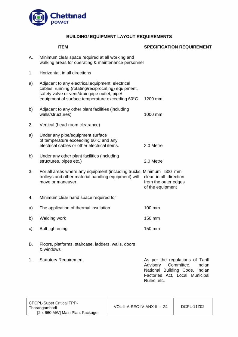
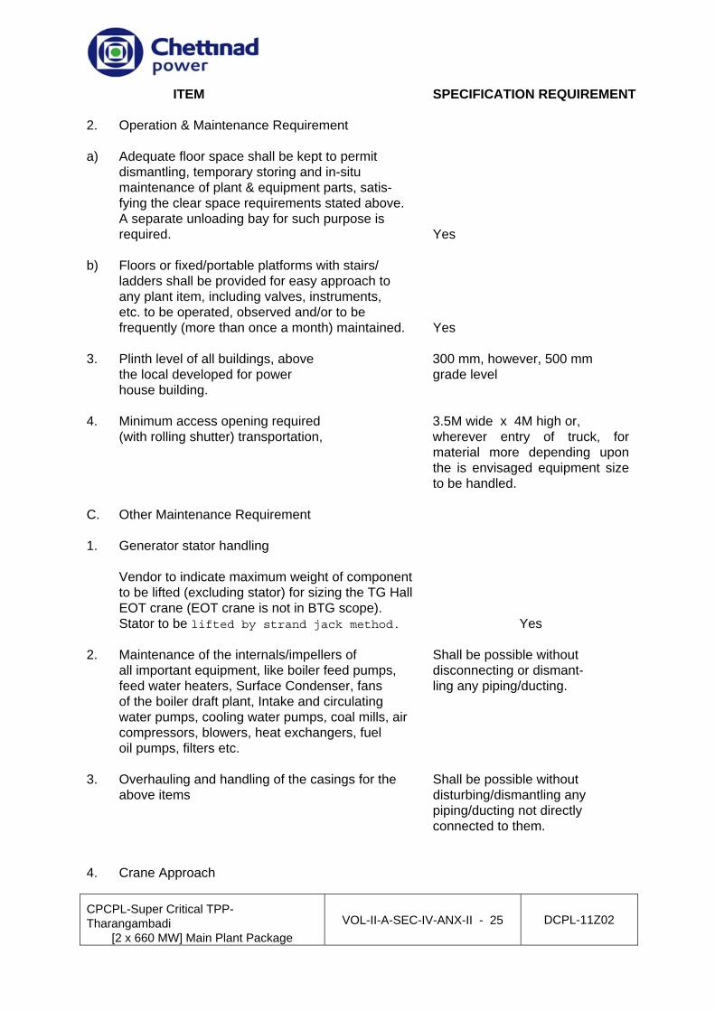


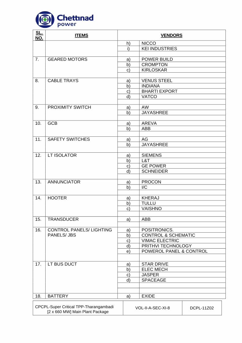


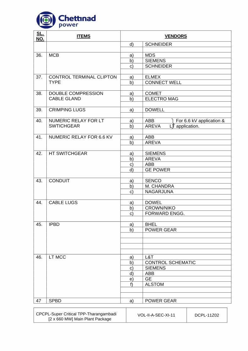


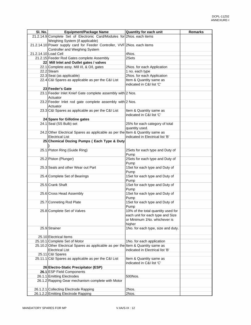


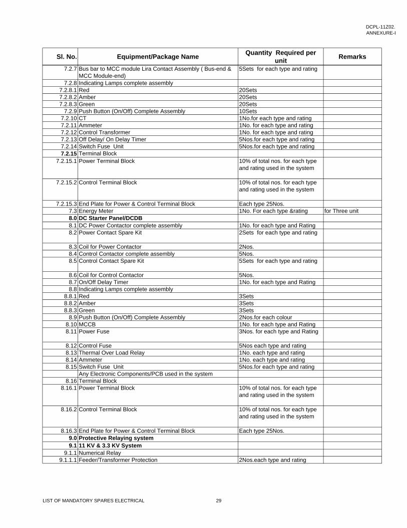
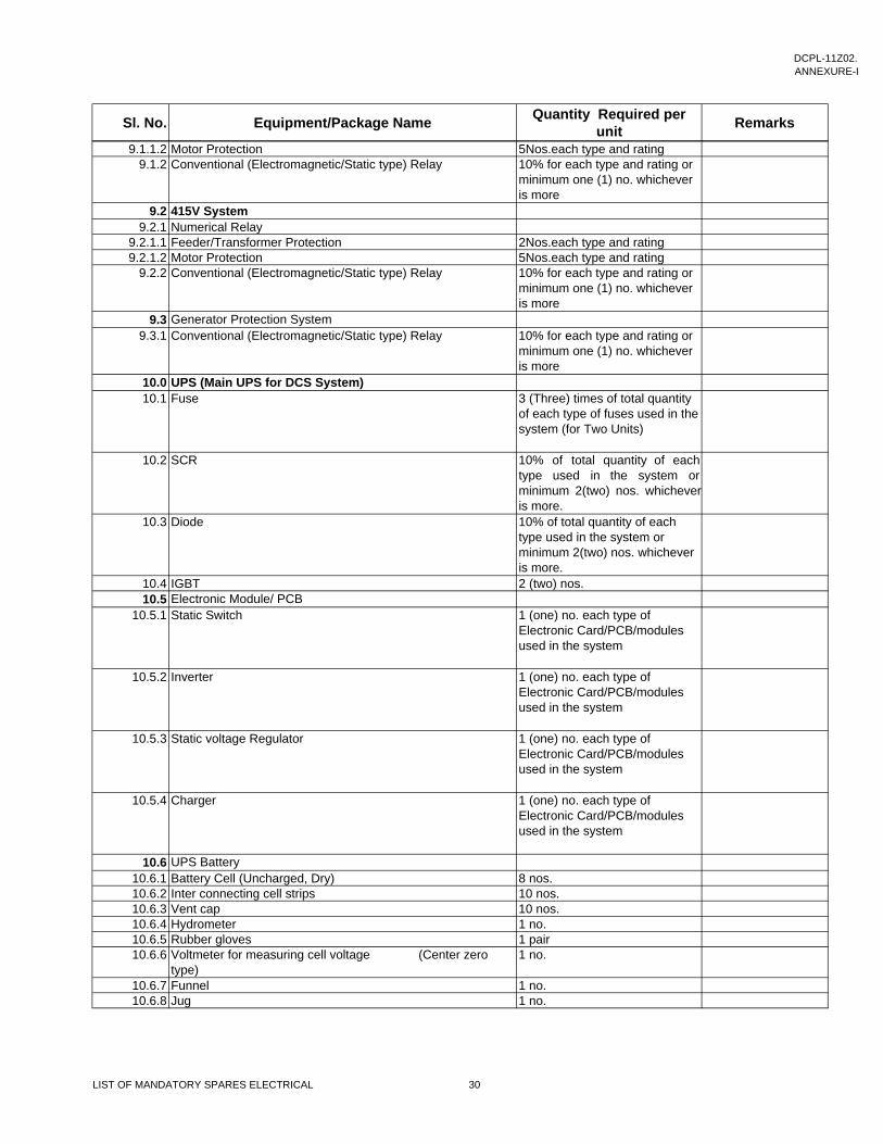


![Untitled-1 [img.staticmb.com] · 2020-01-08 · Dholeshwar Temple - 0.3 kms proposed Riverfront 0.3 kms Indroda park I kms BAPS School I kms Swaminarayan Dham - I kms n Info city-IT](https://static.documents.pub/doc/80x56/5f8b75175802ac46cf710363/untitled-1-img-2020-01-08-dholeshwar-temple-03-kms-proposed-riverfront.jpg)
