15
3-1 EE 319K Introduction to Microcontrollers Lecture 3: Addressing modes, Memory Operations, Subroutines, I/O, Logical/Shift Operations
| Date post: | 13-Dec-2015 |
| Category: |
Documents |
| Upload: | lester-reed |
| View: | 236 times |
| Download: | 0 times |

3-1
EE 319KIntroduction to Microcontrollers
Lecture 3: Addressing modes, Memory Operations, Subroutines,
I/O, Logical/Shift Operations

3-2Ramesh Yerraballi
ldaa

3-3Ramesh Yerraballi
Simple Addressing Modes
Clarifications: Immediate mode can use more than 8-bit values:
ldd #W;RegD=W load a 16-bit constant into RegD lds #W ;SP=W load a 16-bit constant into SP
Branch uses a 8-bit offset however there is a long Branch instruction that can increase this to 16-bits
o bra, bmi, bne, bpl use 8-bit offset: bra rel8 20 rr
o lbra, lbmi, lbne, lbpl, and 16 other long branch instructions use 16-bit offset: lbra rel16 18 20 qq rr
o Jmp uses 16-bit destination address in extended addr mode: jmp opr16 06 hh ll
3-4Ramesh Yerraballi
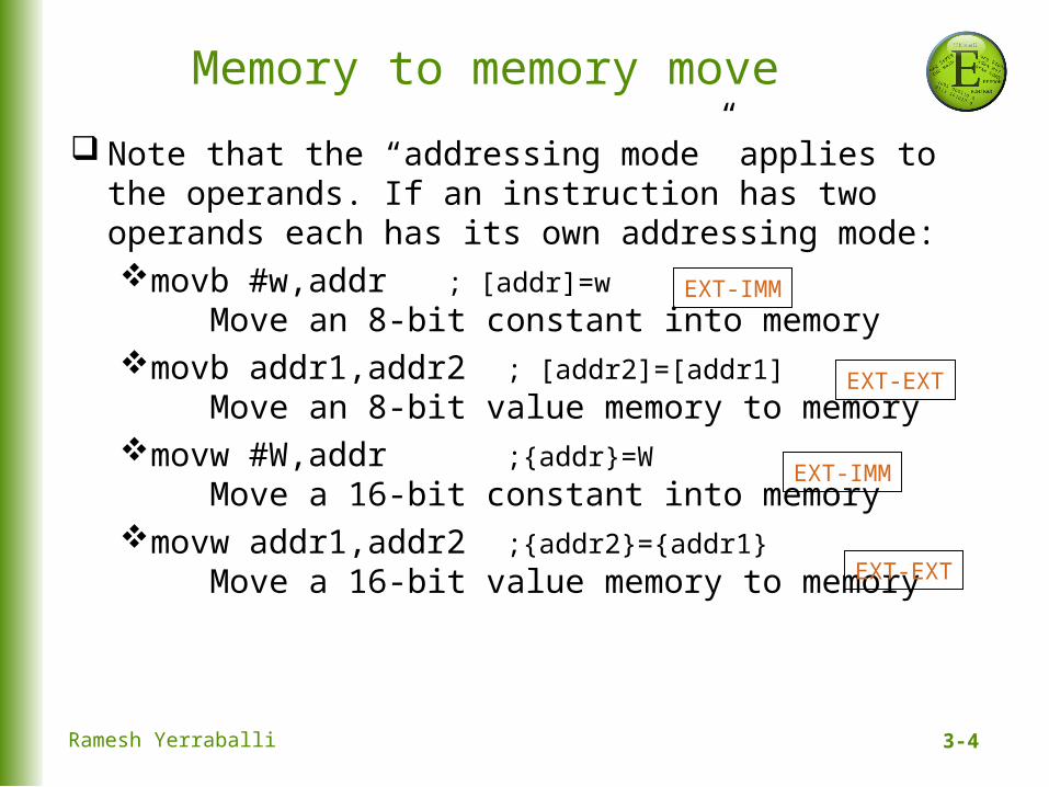
Memory to memory move
Note that the “addressing mode” applies to the operands. If an instruction has two operands each has its own addressing mode:movb #w,addr ; [addr]=w
Move an 8-bit constant into memorymovb addr1,addr2 ; [addr2]=[addr1]
Move an 8-bit value memory to memorymovw #W,addr ;{addr}=W
Move a 16-bit constant into memorymovw addr1,addr2 ;{addr2}={addr1}
Move a 16-bit value memory to memory
EXT-IMM
EXT-EXT
EXT-IMM
EXT-EXT

3-5Ramesh Yerraballi
Subroutines
$0800 org $0800$0800 Flag rmb 1$0801 Data rmb 2$4000 org $4000 ;*****Set************** ; Set Data=1000, and Flag=1 ; Input: None ; Output: None$4000 180303E80801 Set movw #1000,Data ;3$4006 180B010800 movb #1,Flag ;4$400B 3D rts ;5$400C CF4000 main lds #$4000 ;1$400F 07EF bsr Set ;2$4011 20FE loop bra loop ;6$FFFE org $fffe$FFFE 400C fdb main

3-6Ramesh Yerraballi
Stack Use in Subroutines: bsr
bsr Execution:Opcode fetch R 0x400F 0x07 from ROM Phase 1Operand fetch R 0x4010 0xEF from ROM Phase 1Stack store lsbW 0x3FFF 0x11 to RAM Phase 6Stack store msbW 0x3FFE 0x40 to RAM Phase 6
PC
Set movw #1000,Data ;3 movb #1,Flag ;4 rts ;5main lds #$4000 ;1 bsr Set ;2loop bra loop ;6
Stack
SPPC
Set movw #1000,Data ;3 movb #1,Flag ;4 rts ;5main lds #$4000 ;1 bsr Set ;2loop bra loop ;6
Stack
SP $40$11
Before bsr After bsrm ain
Set
1
2
6
Data = 1000
Set
return
3
5
Flag = 0 4
PCPC

3-7Ramesh Yerraballi
Stack Use in Subroutines: rts
rts Execution:
Opcode fetch R 0x4009 0x3D from ROM Phase 1Stack read msb R 0x3FFE 0x40 from RAM Phase 4Stack read lsb R 0x3FFF 0x11 from RAM Phase 4
PC
Set movw #1000,Data ;3 movb #1,Flag ;4 rts ;5main lds #$4000 ;1 bsr Set ;2loop bra loop ;6
Stack
SP $40$11
Before rts
PC
Set movw #1000,Data ;3 movb #1,Flag ;4 rts ;5main lds #$4000 ;1 bsr Set ;2loop bra loop ;
Stack
SP
After rtsm ain
Set
1
2
6
Data = 1000
Set
return
3
5
Flag = 0 4 PCPC

3-8Ramesh Yerraballi
Input/Output: 9S12DP512

3-9Ramesh Yerraballi
I/O Ports and Direction Registers
The input/output direction of a bidirectional port is specified by its direction register.
DDRH, DDRP, DDRJ, DDRT, specify if corresponding pin is input or output: 0 means input 1 means output
9S12 PT7PT6PT5PT4PT3PT2PT1PT0
DDRT=$00
9S12 PT7PT6PT5PT4PT3PT2PT1PT0
DDRT=$0F
9S12 PT7PT6PT5PT4PT3PT2PT1PT0
DDRT=$FF
Address Bit7 6 5 4 3 2 1 Bit0 Name
$0240 PT7 PT6 PT5 PT4 PT3 PT2 PT1 PT0 PTT
$0242 DDRT7 DDRT6 DDRT5 DDRT4 DDRT3 DDRT2 DDRT1 DDRT0 DDRT
3-10Ramesh Yerraballi
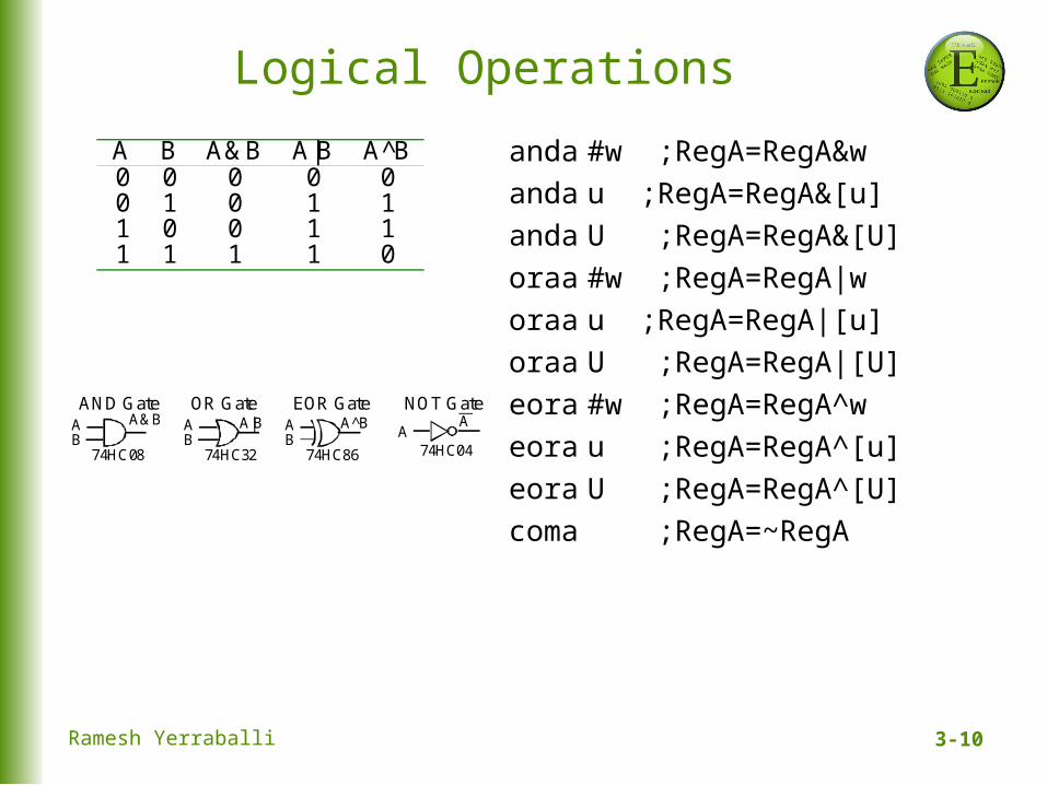
Logical Operations
anda #w ;RegA=RegA&w
anda u ;RegA=RegA&[u]
anda U ;RegA=RegA&[U]
oraa #w ;RegA=RegA|w
oraa u ;RegA=RegA|[u]
oraa U ;RegA=RegA|[U]
eora #w ;RegA=RegA^w
eora u ;RegA=RegA^[u]
eora U ;RegA=RegA^[U]
coma ;RegA=~RegA
AB
A&BAND Gate
74HC08
AB
A|BOR Gate
74HC32
AB
A^BEOR Gate
74HC86
AA
NOT Gate
74HC04
A B A&B A|B A^B0 0 0 0 00 1 0 1 11 0 0 1 11 1 1 1 0

3-11Ramesh Yerraballi
Switch Interfacing
The and operation to extract, or mask, individual bits:Pressed = PTT&0x40;//true if the switch pressed
Assembly:ldaa PTT ;read input Port Tanda #$40 ;clear all bits except bit 6staa Pressed ;true iff the switch is pressed
a7 a6 a5 a4 a3 a2 a1 a0 value of PTT0 1 0 0 0 0 0 0 $40 constant0 a6 0 0 0 0 0 0 result of the anda
3-12Ramesh Yerraballi
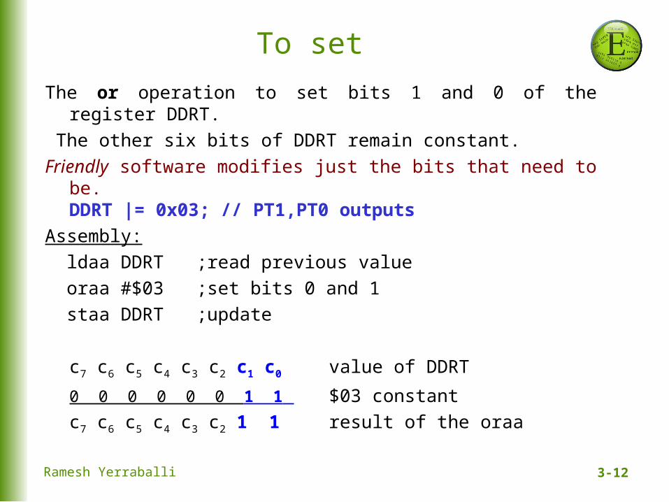
To set
The or operation to set bits 1 and 0 of the register DDRT. The other six bits of DDRT remain constant. Friendly software modifies just the bits that need to be.
DDRT |= 0x03; // PT1,PT0 outputs
Assembly: ldaa DDRT ;read previous value
oraa #$03 ;set bits 0 and 1
staa DDRT ;update
c7 c6 c5 c4 c3 c2 c1 c0 value of DDRT
0 0 0 0 0 0 1 1 $03 constantc7 c6 c5 c4 c3 c2 1 1 result of the oraa

3-13Ramesh Yerraballi
To toggle
The exclusive or operation can also be used to toggle bits.
PTT ^= 0x80; /* toggle PT7 */
Assembly: ldaa PTT ;read output Port T
eora #$80 ;toggle bit 7
staa PTT ;update
b7 b6 b5 b4 b3 b2 b1 b0 value of PTT
1 0 0 0 0 0 0 0 $80 constant~b7 b6 b5 b4 b3 b2 b1 b0 result of the eora

3-14Ramesh Yerraballi
Shift Operation
asla ;RegA=RegA*2
lsla ;RegA=RegA*2
asra ;RegA=RegA/2
lsra ;RegA=RegA/2
C0LSR
CASR
0CLSL/ASL
Use the asla instruction when manipulating signed numbers,
and use the lsla instruction when shifting unsigned numbers

3-15Ramesh Yerraballi
Shift ExampleHigh and Low are unsigned 4-bit components, which will be
combined into a single unsigned 8-bit Result.
Result = (High<<4)|Low; Assembly: ldaa High ;read value of High lsla ;shift into position lsla lsla lsla oraa Low ;combine the two parts staa Result ;save answer
0 0 0 0 h3 h2 h1 h0 value of High
0 0 0 h3 h2 h1 h0 0 after first lsla
0 0 h3 h2 h1 h0 0 0 after second lsla
0 h3 h2 h1 h0 0 0 0 after third lsla
h3 h2 h1 h0 0 0 0 0 after last lsla
0 0 0 0 l3 l2 l1 l0 value of Low
h3 h2 h1 h0 l3 l2 l1 l0 result of the oraa instruction


