3-4 Sept. 2008 EFW INST+SOC PDR 1 Electric Field and Waves (EFW) Spin Plane Boom (SPB) Gregory Dalton Space Sciences Laboratory University of California – Berkeley [email protected]EFW Spin Plane Boom
Overview• Design Requirements/Drivers• Design Overview• Theory of Operation• Flight Heritage• Custom Design for RBSP• Analysis and Testing
Overview
3-4 Sept. 2008 EFW INST+SOC PDR 3
Design Requirements/Drivers
Thermal Interface• Survival: -45 to +60°C• Deployment: -20 to +40°C• Preamp survival: -160 to 80°C• Preamp science range: -55 to +70°C
Mass• NTE 2.42 kg• Currently 1.943 kg with Mounting Feet
Design• Deploy Sensor to 80/100m Tip-to-Tip with 4.7cm resolution• Test/Enable Plug accessible on S/C• Mount at 10° angle to S/C Panel• 7 Conductor Cable to Preamp• Preamp Enclosure designed for ease of assembly• Keyreel designed to unfurl Fine Wire at 10m & 15 RPM
3-4 Sept. 2008 EFW INST+SOC PDR 4
Design Overview – Overall Dims
[cm]inch
SPHERE
PREAMPLIFIERENCLOSURE
COMPOSITECABLE
FINEWIRE
3-4 Sept. 2008 EFW INST+SOC PDR 5
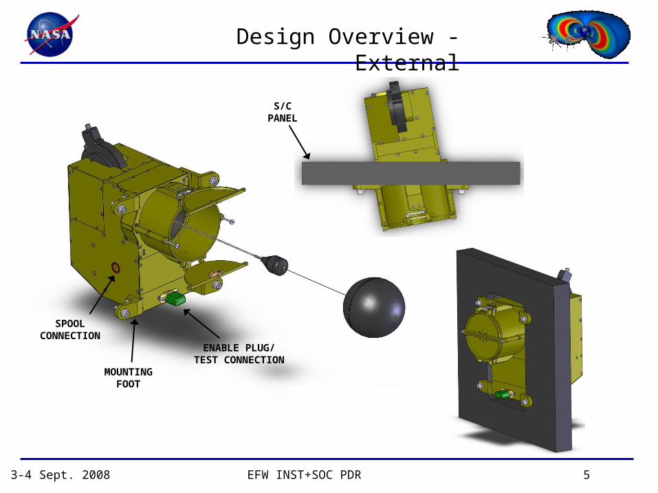
Design Overview - External
ENABLE PLUG/TEST CONNECTION
MOUNTINGFOOT
SPOOLCONNECTION
S/CPANEL
3-4 Sept. 2008 EFW INST+SOC PDR 6
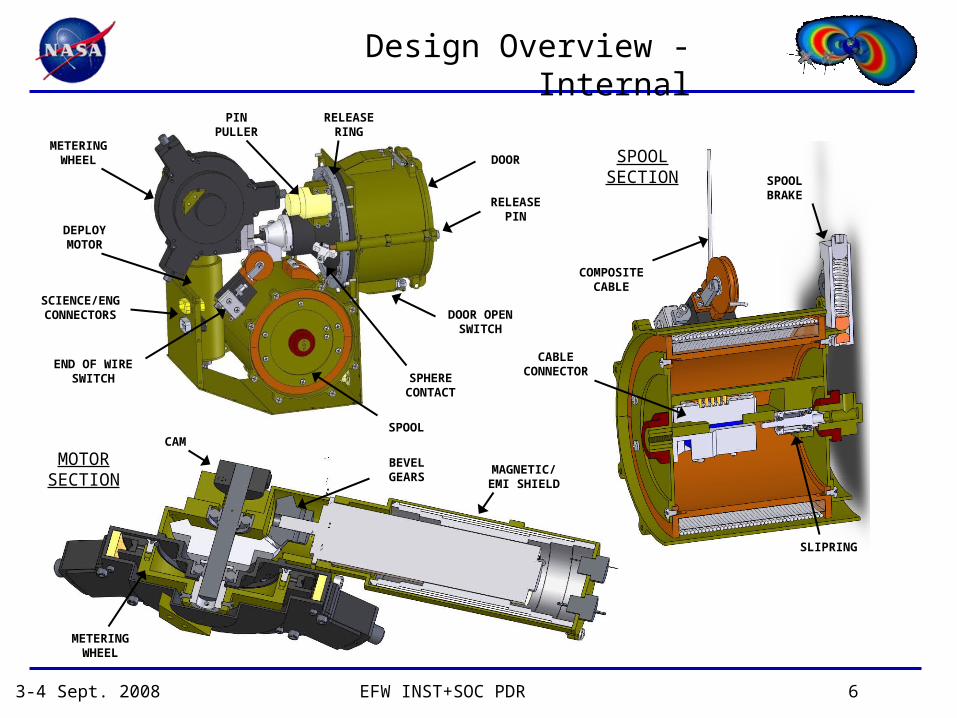
Design Overview - Internal
SPHERECONTACT
DOOR OPENSWITCH
RELEASEPIN
DOOR
RELEASERING
PINPULLER
METERINGWHEEL
DEPLOYMOTOR
SCIENCE/ENGCONNECTORS
END OF WIRESWITCH
SPOOL
SPOOLBRAKE
CABLECONNECTOR
COMPOSITECABLE
SLIPRING
SPOOLSECTION
MOTORSECTION
MAGNETIC/EMI SHIELD
BEVELGEARS
CAM
METERINGWHEEL
3-4 Sept. 2008 EFW INST+SOC PDR 7
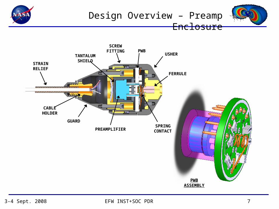
Design Overview – Preamp Enclosure
STRAINRELIEF
TANTALUMSHIELD
SCREWFITTING PWB
USHER
FERRULE
CABLEHOLDER
GUARD
PREAMPLIFIERSPRING
CONTACT
PWBASSEMBLY
3-4 Sept. 2008 EFW INST+SOC PDR 8
Theory of Operation
Integration and Launch
• Stowed and Unpowered
• Composite Cable on Spool, held by Brake
• Sphere and Preamp caged by Doors
• Doors held closed by Release Pins
3-4 Sept. 2008 EFW INST+SOC PDR 9
Theory of Operation
Deployment
• Release Ring rotates when Pin Puller Actuated
• Release pins move clear of Doors
• Doors open, indicated
• Motor pulls cable off Spool at ~2cm/s and meters Cable every 4.7cm
• At 10m and 15RPM, Fine Wire Unfurls
• End of Travel switch disables motor power
3-4 Sept. 2008 EFW INST+SOC PDR 10
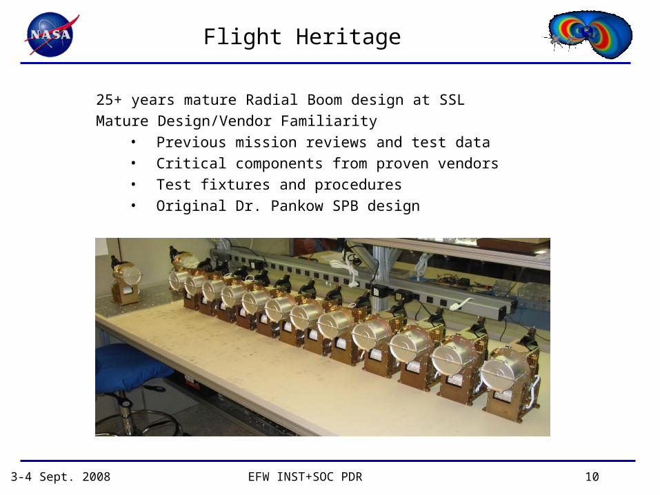
Flight Heritage
25+ years mature Radial Boom design at SSL
Mature Design/Vendor Familiarity• Previous mission reviews and test data• Critical components from proven vendors• Test fixtures and procedures• Original Dr. Pankow SPB design
3-4 Sept. 2008 EFW INST+SOC PDR 11
Custom Use for RBSP
Gore Cable
• 100m Tip to Tip (~49m per boom)
• No coax
• Kapton vs. PTFE insulation
Simplified Release Mechanism
• Pin Puller
• Secures own Power
• Redundant
Packaged for RBSP
• Completely enclosed
• Panel Mount
Electronics
• Modified Harness
• Door Open Indication
RBSP Composite Cable
3-4 Sept. 2008 EFW INST+SOC PDR 12
Analysis - Damping
y = 6.7389e -0.1279x
-8
-6
-4
-2
0
2
4
6
8
0 1 2 3 4 5 6 7 8 9
time (s)
amplitude (deg)
Pendulum Motion
Max Half Angle
Curve Fit
Cable Damping (J/rad^2)CRRES -0.031
RBSP ETU -0.0153
Energy Dissipated per cycle per boom:
Cable Damping Test•Simple Pendulum test•Tip Mass Simulates Cable Load•Future test to include accurate RBSP tip mass and vacuum environment
3-4 Sept. 2008 EFW INST+SOC PDR 13
Analysis - CTE
Coefficient of Thermal Expansion• Design for low CTE• Test from 20 – 80°C• 12ppm/°C from RBSP
prototype
ConstantForce
Thermal Shroud
CableLoadCell
Interfere-ometer
LaserElectronics
PC/LabView
Displacementcart
Reflector
Thermocouples
ThermalIsolator
ThermalIsolator
3-4 Sept. 2008 EFW INST+SOC PDR 14
Setpoints and Margins
Fine Wire:
• 0.009”ø, 7x7 strands, stress relieved stainless steel Construction
• > 50N breaking strength, tested with end conditions
• > 10:1 pulley to cable diameter ratio, de-rate cable strength to 85% -> 42N
• Continuous torque: 2120mNm (x2 after Bevel gears)
• Max intermittent: 4240mNm (x2 after Bevel gears)
• Torque to break shear pin: 4050mNm
SPB Structure First Mode – 300hz
3-4 Sept. 2008 EFW INST+SOC PDR 15
Testing
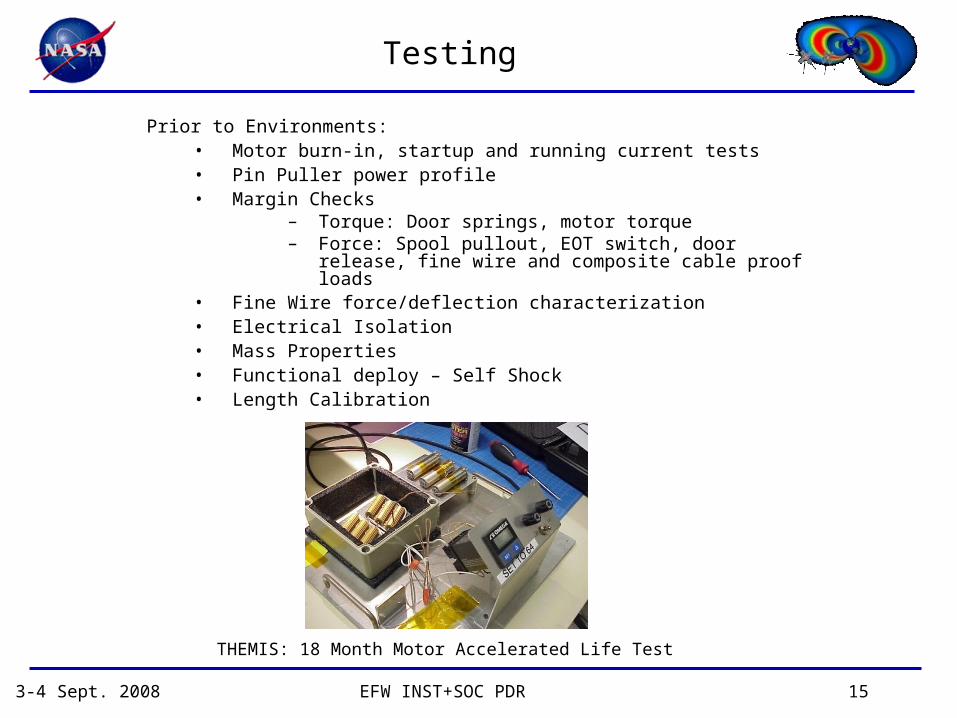
Prior to Environments:• Motor burn-in, startup and running current tests• Pin Puller power profile• Margin Checks
– Torque: Door springs, motor torque– Force: Spool pullout, EOT switch, door release, fine wire
and composite cable proof loads• Fine Wire force/deflection characterization• Electrical Isolation• Mass Properties• Functional deploy – Self Shock• Length Calibration
THEMIS: 18 Month Motor Accelerated Life Test
3-4 Sept. 2008 EFW INST+SOC PDR 16
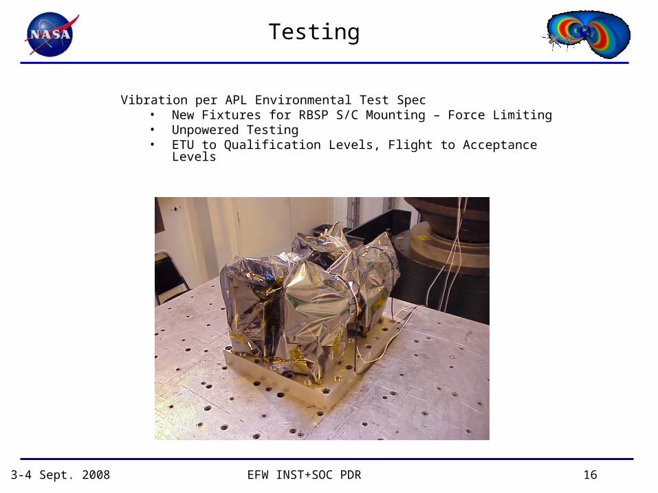
Testing
Vibration per APL Environmental Test Spec• New Fixtures for RBSP S/C Mounting – Force Limiting• Unpowered Testing• ETU to Qualification Levels, Flight to Acceptance Levels