3.1 Introduction The shapes which are adopted for structural elements are affected, to a large extent, by the nature of the materials from which they are made. The physical properties of materials determine the types of internal force which they can carry and, therefore, the types of element for which they are suitable. Unreinforced masonry, for example, may only be used in situations where compressive stress is present. Reinforced concrete performs well when loaded in compression or bending, but not particularly well in axial tension. The processes by which materials are manufactured and then fashioned into structural elements also play a role in determining the shapes of elements for which they are suitable. These aspects of the influence of material properties on structural geometry are now discussed in relation to the four principal structural materials of masonry, timber, steel and reinforced concrete. 3.2 Masonry Masonry is a composite material in which individual stones, bricks or blocks are bedded in mortar to form columns, walls, arches or vaults (Fig. 3.1). The range of different types of masonry is large due to the variety of types of constituent. Bricks may be of fired clay, baked earth, concrete, or a range of similar materials, and blocks, which are simply very large bricks, can be similarly composed. Stone too is not one but a very wide range of materials, from the relatively soft sedimentary rocks such as limestone to the very hard granites and other igneous rocks. These ‘solid’ units can be used in conjunction with a variety of different mortars to produce a range of masonry types. All have certain properties in common and therefore produce similar types of structural element. Other materials such as dried mud, pisé or even unreinforced concrete have similar properties and can be used to make similar types of element. The physical properties which these materials have in common are moderate compressive strength, minimal tensile strength and relatively high density. The very low tensile strength restricts the use of masonry to elements in which the principal internal force is compressive, i.e. columns, walls and compressive form-active types (see Section 4.2) such as arches, vaults and domes. In post-and-beam forms of structure (see Section 5.2) it is normal for only the vertical elements to be of masonry. Notable exceptions are the Greek temples (see Fig. 7.1), but in these the spans of such horizontal elements as are made in stone are kept short by subdivision of the interior space by rows of columns or walls. Even so, most of the elements which span horizontally are in fact of timber and only the most obvious, those in the exterior walls, are of stone. Where large horizontal spans are constructed in masonry compressive form-active shapes must be adopted (Fig. 3.1). Where significant bending moment occurs in masonry elements, for example as a consequence of side thrusts on walls from rafters or vaulted roof structures or from out-of- plane wind pressure on external walls, the level of tensile bending stress is kept low by making the second moment of area (see Appendix 2) of 22 Chapter 3 Structural materials
Transcript
3.1 Introduction
The shapes which are adopted for structuralelements are affected, to a large extent, by thenature of the materials from which they aremade. The physical properties of materialsdetermine the types of internal force whichthey can carry and, therefore, the types ofelement for which they are suitable.Unreinforced masonry, for example, may onlybe used in situations where compressive stressis present. Reinforced concrete performs wellwhen loaded in compression or bending, butnot particularly well in axial tension.
The processes by which materials aremanufactured and then fashioned intostructural elements also play a role indetermining the shapes of elements for whichthey are suitable. These aspects of theinfluence of material properties on structuralgeometry are now discussed in relation to thefour principal structural materials of masonry,timber, steel and reinforced concrete.
3.2 Masonry
Masonry is a composite material in whichindividual stones, bricks or blocks are beddedin mortar to form columns, walls, arches orvaults (Fig. 3.1). The range of different types ofmasonry is large due to the variety of types ofconstituent. Bricks may be of fired clay, bakedearth, concrete, or a range of similar materials,and blocks, which are simply very large bricks,can be similarly composed. Stone too is notone but a very wide range of materials, fromthe relatively soft sedimentary rocks such aslimestone to the very hard granites and other
igneous rocks. These ‘solid’ units can be usedin conjunction with a variety of differentmortars to produce a range of masonry types.All have certain properties in common andtherefore produce similar types of structuralelement. Other materials such as dried mud,pisé or even unreinforced concrete have similarproperties and can be used to make similartypes of element.
The physical properties which thesematerials have in common are moderatecompressive strength, minimal tensile strengthand relatively high density. The very low tensilestrength restricts the use of masonry toelements in which the principal internal forceis compressive, i.e. columns, walls andcompressive form-active types (see Section4.2) such as arches, vaults and domes.
In post-and-beam forms of structure (seeSection 5.2) it is normal for only the verticalelements to be of masonry. Notable exceptionsare the Greek temples (see Fig. 7.1), but inthese the spans of such horizontal elements asare made in stone are kept short bysubdivision of the interior space by rows ofcolumns or walls. Even so, most of theelements which span horizontally are in fact oftimber and only the most obvious, those in theexterior walls, are of stone. Where largehorizontal spans are constructed in masonrycompressive form-active shapes must beadopted (Fig. 3.1).
Where significant bending moment occurs inmasonry elements, for example as aconsequence of side thrusts on walls fromrafters or vaulted roof structures or from out-of-plane wind pressure on external walls, the levelof tensile bending stress is kept low by makingthe second moment of area (see Appendix 2) of22
Chapter 3
Structural materials
the cross-section large. This can give rise tovery thick walls and columns and, therefore, toexcessively large volumes of masonry unlesssome form of ‘improved’ cross-section (seeSection 4.3) is used. Traditional versions of thisare buttressed walls. Those of medieval Gothiccathedrals or the voided and sculptured wallswhich support the large vaulted enclosures ofRoman antiquity (see Figs 7.30 to 7.32) areamong the most spectacular examples. In all ofthese the volume of masonry is small in
relation to the total effective thickness of thewall concerned. The fin and diaphragm walls ofrecent tall single-storey masonry buildings (Fig.3.2) are twentieth-century equivalents. In themodern buildings the bending moments whichoccur in the walls are caused principally bywind loading and not by the lateral thrustsfrom roof structures. Even where ‘improved’cross-sections are adopted the volume ofmaterial in a masonry structure is usually largeand produces walls and vaults which act as 23
Structural materials
Fig. 3.1 Chartres Cathedral,France, twelfth and thirteenthcenturies. The Gothic churchincorporates most of the variousforms for which masonry issuitable. Columns, walls andcompressive form-active archesand vaults are all visible here.(Photo: Courtauld Institute)
effective thermal, acoustic and weathertightbarriers.
The fact that masonry structures are composedof very small basic units makes their constructionrelatively straightforward. Subject to the structuralconstraints outlined above, complex geometriescan be produced relatively easily, without theneed for sophisticated plant or techniques andvery large structures can be built by these simplemeans (Fig. 3.3). The only significantconstructional drawback of masonry is thathorizontal-span structures such as arches andvaults require temporary support until complete.
Other attributes of masonry-type materials arethat they are durable, and can be left exposed inboth the interiors and exteriors of buildings. Theyare also, in most locations, available locally insome form and do not therefore require to betransported over long distances. In other words,masonry is an environmentally friendly materialthe use of which must be expected to increase inthe future.
Structure and Architecture
24
Fig. 3.2 Where masonry will be subjected to significantbending moment, as in the case of external walls exposedto wind loading, the overall thickness must be largeenough to ensure that the tensile bending stress is notgreater than the compressive stress caused by thegravitational load. The wall need not be solid, however,and a selection of techniques for achieving thicknessefficiently is shown here.
(a)
(b) (c)
Fig. 3.3 Town Walls, Igerman, Iran. This late mediaevalbrickwork structure demonstrates one of the advantages ofmasonry, which is that very large constructions withcomplex geometries can be achieved by relatively simplebuilding processes.
3.3 Timber
Timber has been used as a structural materialfrom earliest times. It possesses both tensileand compressive strength and, in the structuralrole is therefore suitable for elements whichcarry axial compression, axial tension andbending-type loads. Its most widespreadapplication in architecture has been inbuildings of domestic scale in which it hasbeen used to make complete structuralframeworks, and for the floors and roofs inloadbearing masonry structures. Rafters, floorbeams, skeleton frames, trusses, built-upbeams of various kinds, arches, shells andfolded forms have all been constructed intimber (Figs 3.4, 3.6, 3.9 and 3.10).
The fact of timber having been a livingorganism is responsible for the nature of itsphysical properties. The parts of the tree whichare used for structural timber – the heartwoodand sapwood of the trunk – have a structuralfunction in the living tree and therefore have,in common with most organisms, very goodstructural properties. The material iscomposed of long fibrous cells aligned parallelto the original tree trunk and therefore to thegrain which results from the annual rings. Thematerial of the cell walls gives timber itsstrength and the fact that its constituentelements are of low atomic weight isresponsible for its low density. The lightness inweight of timber is also due to its cellularinternal structure which produces elementcross-sections which are permanently‘improved’ (see Section 4.3).
Parallel to the grain, the strength isapproximately equal in tension and compressionso that planks aligned with the grain can beused for elements which carry axialcompression, axial tension or bending-typeloads as noted above. Perpendicular to the grainit is much less strong because the fibres areeasily crushed or pulled apart when subjected tocompression or tension in this direction.
This weakness perpendicular to the graincauses timber to have low shear strength whensubjected to bending-type loads and alsomakes it intolerant of the stress concentrations
such as occur in the vicinity of mechanicalfasteners such as bolts and screws. This can bemitigated by the use of timber connectors,which are devices designed to increase thearea of contact through which load istransmitted in a joint. Many different designsof timber connector are currently available(Fig. 3.5) but, despite their development, thedifficulty of making satisfactory structuralconnections with mechanical fasteners is afactor which limits the load carrying capacity oftimber elements, especially tensile elements.
The development in the twentieth century ofstructural glues for timber has to some extentsolved the problem of stress concentration atjoints, but timber which is to be glued must bevery carefully prepared if the joint is to developits full potential strength and the curing of theglue must be carried out under controlledconditions of temperature and relativehumidity1. This is impractical on building sites
25
Structural materials
Fig. 3.4 Methodist church, Haverhill, Suffolk, UK; J. W.Alderton, architect. A series of laminated timber portalframes is used here to provide a vault-like interior. Timberis also used for secondary structural elements and interiorlining. (Photo: S. Baynton)
1 A good explanation of the factors which affect thegluing of timber can be found in Gordon, J. E., The NewScience of Strong Materials, Penguin, London, 1968.
and has to be regarded as a pre-fabricatingtechnique.
Timber suffers from a phenomenon knownas ‘moisture movement’. This arises becausethe precise dimensions of any piece of timberare dependent on its moisture content (theratio of the weight of water which it contains toits dry weight, expressed as a percentage). Thisis affected by the relative humidity of theenvironment and as the latter is subject tocontinuous change, the moisture content andtherefore the dimensions of timber alsofluctuate continuously. Timber shrinksfollowing a reduction in moisture content dueto decreasing relative humidity and swells ifthe moisture content increases. So far as thestructural use of timber is concerned, one ofthe most serious consequences of this is thatjoints made with mechanical fasteners tend towork loose.
The greatest change to the moisture contentof a specimen of timber occurs following thefelling of a tree after which it undergoes areduction from a value of around 150 per centin the living tree to between 10 and 20 percent, which is the normal range for moisturecontent of timber in a structure. This initialdrying out causes a large amount of shrinkageand must be carried out in controlled
conditions if damage to the timber is to beavoided. The controlled drying out of timber isknown as seasoning. It is a process in whichthe timber must be physically restrained toprevent the introduction of permanent twistsand other distortions caused by the differentialshrinkage which inevitably occurs, on atemporary basis, due to unevenness in thedrying out. The amount of differentialshrinkage must be kept to a minimum and thisfavours the cutting of the timber into plankswith small cross-sections, because the greatestvariation in moisture content occurs betweentimber at the core of a plank and that at thesurface where evaporation of moisture takesplace.
Timber elements can be either of sawntimber, which is simply timber cut directlyfrom a tree with little further processing otherthan shaping and smoothing, or manufacturedproducts, to which further processing has beenapplied. Important examples of the latter arelaminated timber and plywood.
The forms in which sawn timber is availableare, to a large extent, a consequence of thearboreal origins of the material. It isconvenient to cut planks from tree trunks bysawing parallel to the trunk direction and thisproduces straight, parallel-sided elements with
Structure and Architecture
26
Fig. 3.5 Timberconnectors are used toreduce the concentrationof stress in boltedconnections. A selectionof different types isshown here.
(a) (b) (c)
rectangular cross-sections. Basic sawn-timbercomponents are relatively small (maximumlength around 6 m and maximum cross-sectionaround 75 mm � 250 mm) due partly to theobvious fact that the maximum sizes of cross-section and length are governed by the size ofthe original tree, but also to the desirability ofhaving small cross-sections for the seasoningprocess. They can be combined to form larger,composite elements such as trusses withnailed, screwed or bolted connections. Thescale of structural assemblies is usuallymodest, however, due to both the small sizesof the constituent planks and to the difficulty(already discussed) of making good structuralconnections with mechanical fasteners.
Timber is used in loadbearing-wallstructures both as the horizontal elements inmasonry buildings (see Fig. 1.13) and in all-timber configurations in which vertical timberelements are spaced close together to formwall panels (Fig. 3.6). The use of timber inskeleton frame structures (beams and columnsas opposed to closely spaced joists and wallpanels) is less common because theconcentration of internal forces which occursin these normally requires that a strongermaterial such as steel be adopted. In all casesspans are relatively small, typically 5 m forfloor structures of closely spaced joists ofrectangular cross-section, and 20 m for roofstructures with triangulated elements. All-timber structures rarely have more than two orthree storeys.
Timber products are manufactured by gluingsmall timber elements together in conditionsof close quality control. They are intended toexploit the advantages of timber while at thesame time minimising the effects of itsprincipal disadvantages, which are variability,dimensional instability, restrictions in the sizesof individual components and anisotropicbehaviour. Examples of timber products arelaminated timber, composite boards such asplywood, and combinations of sawn timberand composite board (Fig. 3.7).
Laminated timber (Fig. 3.7c) is a product inwhich elements with large rectangular cross-sections are built up by gluing together smaller
solid timber elements of rectangular cross-section. The obvious advantage of the processis that it allows the manufacture of solidelements with much larger cross-sections thanare possible in sawn timber. Very longelements are also possible because theconstituent boards are jointed end-to-end bymeans of finger joints (Fig. 3.8). The laminatingprocess also allows the construction ofelements which are tapered or have curved 27
Structural materials
Fig. 3.6 The all-timber house is a loadbearing wall form ofconstruction in which all of the structural elements in the walls, floorsand roof are of timber. An internal wall of closely spaced sawn-timberelements is here shown supporting the upper floor of a two-storeybuilding. Note temporary bracing which is necessary for stability untilcross-walls are inserted. (Photo: A. Macdonald)
profiles. Arches (Figs 3.9 and 3.10) and portalframe elements (Fig. 3.4) are examples of this.
The general quality and strength oflaminated timber is higher than that of sawntimber for two principal reasons. Firstly, theuse of basic components which have smallcross-sections allows more effective seasoning,with fewer seasoning defects than can beachieved with large sawn-timber elements.Secondly, the use of the finger joint, whichcauses a minimal reduction in strength in theconstituent boards, allows any major defectswhich are present in these to be cut out. Theprincipal use of laminated timber is as anextension to the range of sawn-timberelements and it is employed in similarstructural configurations – for example asclosely spaced joists – and allows larger spansto be achieved. The higher strength oflaminated timber elements also allows it to beused effectively in skeleton frame construction.
Composite boards are manufacturedproducts composed of wood and glue. Thereare various types of these including plywood,blockboard and particle board, all of which areavailable in the form of thin sheets. The levelof glue impregnation is high and this impartsgood dimensional stability and reduces the
Structure and Architecture
28
Fig. 3.7 The I-beamwith the plywood web(b) and the laminatedbeam (c) are examplesof manufactured timberproducts. Thesenormally have bettertechnical propertiesthan plain sawn timberelements such as thatshown in (a). The highlevels of glueimpregnation inmanufactured beamsreduce dimensionalinstability, and majordefects, such as knots,are removed fromconstituent sub-elements.
Fig. 3.8 ‘Finger’ joints allow the constituent boards oflaminated timber elements to be produced in long lengths.They also make possible the cutting out of defects such asknots. (Photo: TRADA)
(a)
(b)
(c)
Fig. 3.9 Sports Dome, Perth, Scotland, UK. Laminatedtimber built-up sections can be produced in a variety ofconfigurations in addition to straight beams. Here a seriesof arch elements is used to produce the framework of adome.
extent to which anisotropic behaviour occurs.Most composite boards also have highresistance to splitting at areas of stressconcentration around nails and screws.
Composite boards are used as secondarycomponents such as gusset plates in built-uptimber structures. Another common use is asthe web elements in composite beams of I- orrectangular-box section in which the flangesare sawn timber (Figs 3.11 and 3.12). 29
Structural materials
Fig. 3.10 David LloydTennis Centre, London,UK. The primarystructural elements arelaminated timber archeswhich span 35 m.(Photo: TRADA)
Fig. 3.11 Built-up-beams with I-shaped cross-sectionsconsisting of sawn timber flanges connected by aplywood web. The latter is corrugated which allows thenecessary compressive stability to be achieved with avery thin cross-section. (Photo: Finnish PlywoodInternational)
Fig. 3.12 Sports Stadium at Lähderanta, Sweden. Theprimary structural elements are plywood timber archeswith rectangular box cross-sections. (Photo: FinnishPlywood International)
To sum up, timber is a material which offersthe designers of buildings a combination ofproperties that allow the creation oflightweight structures which are simple toconstruct. However, its relatively low strength,the small sizes of the basic components andthe difficulties associated with achieving goodstructural joints tend to limit the size ofstructure which is possible, and the majority oftimber structures are small in scale with shortspans and a small number of storeys.Currently, its most common application inarchitecture is in domestic building where it isused as a primary structural material either toform the entire structure of a building, as intimber wall-panel construction, or as thehorizontal elements in loadbearing masonrystructures.
3.4 Steel
The use of steel as a primary structuralmaterial dates from the late nineteenth centurywhen cheap methods for manufacturing it on alarge scale were developed. It is a material thathas good structural properties. It has highstrength and equal strength in tension andcompression and is therefore suitable for thefull range of structural elements and will resistaxial tension, axial compression and bending-type load with almost equal facility. Its densityis high, but the ratio of strength to weight isalso high so that steel components are notexcessively heavy in relation to their loadcarrying capacity, so long as structural formsare used which ensure that the material isused efficiently. Therefore, where bendingloads are carried it is essential that ‘improved’
Structure and Architecture
30
Fig. 3.13 Hopkins House, London, UK; Michael Hopkins, architect; Anthony Hunt Associates, structural engineers. Thefloor structure here consists of profiled steel sheeting which will support a timber deck. A more common configuration isfor the profiled steel deck to act compositely with an in situ concrete slab for which it serves as permanent formwork.(Photo: Pat Hunt)
cross-sections (see Section 4.3) andlongitudinal profiles are adopted.
The high strength and high density of steelfavours its use in skeleton frame typestructures in which the volume of the structureis low in relation to the total volume of thebuilding which is supported, but a limitedrange of slab-type formats is also used. Anexample of a structural slab-type element isthe profiled floor deck in which a profiled steeldeck is used in conjunction with concrete, orexceptionally timber (Fig. 3.13), to form acomposite structure. These have ‘improved’corrugated cross-sections to ensure thatadequate levels of efficiency are achieved. Deckunits consisting of flat steel plate areuncommon.
The shapes of steel elements are greatlyinfluenced by the process which is used toform them. Most are shaped either by hot-rolling or by cold-forming. Hot-rolling is aprimary shaping process in which massive red-hot billets of steel are rolled between severalsets of profiled rollers. The cross-section of theoriginal billet, which is normally cast fromfreshly manufactured steel and is usuallyaround 0.5 m � 0.5 m square, is reduced bythe rolling process to much smallerdimensions and to a particular precise shape(Fig. 3.14). The range of cross-section shapeswhich are produced is very large and eachrequires its own set of finishing rollers.Elements that are intended for structural usehave shapes in which the second moment ofarea (see Appendix 2.3) is high in relation tothe total area (Fig. 3.15). I- and H- shapes ofcross-section are common for the largeelements which form the beams and columnsof structural frameworks. Channel and angleshapes are suitable for smaller elements suchas secondary cladding supports and sub-elements in triangulated frameworks. Square,circular and rectangular hollow sections areproduced in a wide range of sizes as are flatplates and solid bars of various thicknesses.Details of the dimensions and geometricproperties of all the standard sections arelisted in tables of section properties producedby steelwork manufacturers.
Structural materials
Fig. 3.14 The heaviest steel sections are produced by ahot-rolling process in which billets of steel are shaped byprofiled rollers. This results in elements which are straight,parallel sided and of constant cross-section. Thesefeatures must be taken into account by the designer whensteel is used in building and the resulting restrictions inform accepted. (Photo: British Steel)
Fig. 3.15 Hot-rolled steel elements. 31
The other method by which large quantitiesof steel components are manufactured is cold-forming. In this process thin, flat sheets ofsteel, which have been produced by the hot-rolling process, are folded or bent in the coldstate to form structural cross-sections (Fig.3.16). The elements which result have similarcharacteristics to hot-rolled sections, in thatthey are parallel sided with constant cross-sections, but the thickness of the metal ismuch less so that they are both much lighterand, of course, have lower load carryingcapacities. The process allows morecomplicated shapes of cross-section to beachieved, however. Another difference fromhot-rolling is that the manufacturingequipment for cold-forming is much simplerand can be used to produce tailor-made cross-sections for specific applications. Due to theirlower carrying capacities cold-formed sectionsare used principally for secondary elements inroof structures, such as purlins, and forcladding support systems. Their potential forfuture development is enormous.
Structural steel components can also beproduced by casting, in which case verycomplex tailor-made shapes are possible. Thetechnique is problematic when used forstructural components, however, due to thedifficulty of ensuring that the castings are
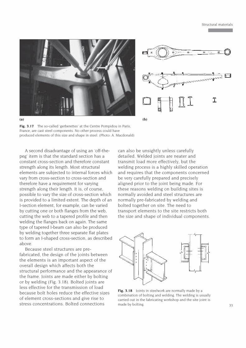
sound and of consistent quality throughout. Inthe early years of ferrous metal structures inthe nineteenth century, when casting waswidely used, many structural failures occurred– most notably that of the Tay Railway Bridgein Scotland in 1879. The technique was rarelyused for most of the twentieth century buttechnical advances made possible its re-introduction. Prominent recent examples arethe ‘gerberettes’ at the Centre Pompidou, Paris(Figs 3.17 & 7.7) and the joints in the steelworkof the train shed at Waterloo Station, London(Fig. 7.17).
Most of the structural steelwork used inbuilding consists of elements of the hot-rolledtype and this has important consequences forthe layout and overall form of the structures.An obvious consequence of the rolling processis that the constituent elements are prismatic:they are parallel-sided with constant cross-sections and they are straight – this tends toimpose a regular, straight-sided format on thestructure (see Figs iv, 1.10 and 7.26). In recentyears, however, methods have been developedfor bending hot-rolled structural steelelements into curved profiles and this hasextended the range of forms for which steelcan be used. The manufacturing process does,however, still impose quite severe restrictionson the overall shape of structure for whichsteel can be used.
The manufacturing process also affects thelevel of efficiency which can be achieved insteel structures, for several reasons. Firstly, itis not normally possible to produce specifictailor-made cross-sections for particularapplications because special rollingequipment would be required to producethem and the capital cost of this wouldnormally be well beyond the budget of anindividual project. Standard sections mustnormally be adopted in the interests ofeconomy, and efficiency is compromised as aresult. An alternative is the use of tailor-madeelements built up by welding togetherstandard components, such as I-sections builtup from flat plate. This involves highermanufacturing costs than the use of standardrolled sections.
Structure and Architecture
32
Fig. 3.16 Cold-formed sections areformed from thinsteel sheet. A greatervariety of cross-section shapes ispossible than with thehot-rolling process.
A second disadvantage of using an ‘off-the-peg’ item is that the standard section has aconstant cross-section and therefore constantstrength along its length. Most structuralelements are subjected to internal forces whichvary from cross-section to cross-section andtherefore have a requirement for varyingstrength along their length. It is, of course,possible to vary the size of cross-section whichis provided to a limited extent. The depth of anI-section element, for example, can be variedby cutting one or both flanges from the web,cutting the web to a tapered profile and thenwelding the flanges back on again. The sametype of tapered I-beam can also be producedby welding together three separate flat platesto form an I-shaped cross-section, as describedabove.
Because steel structures are pre-fabricated, the design of the joints betweenthe elements is an important aspect of theoverall design which affects both thestructural performance and the appearance ofthe frame. Joints are made either by boltingor by welding (Fig. 3.18). Bolted joints areless effective for the transmission of loadbecause bolt holes reduce the effective sizesof element cross-sections and give rise tostress concentrations. Bolted connections
can also be unsightly unless carefullydetailed. Welded joints are neater andtransmit load more effectively, but thewelding process is a highly skilled operationand requires that the components concernedbe very carefully prepared and preciselyaligned prior to the joint being made. Forthese reasons welding on building sites isnormally avoided and steel structures arenormally pre-fabricated by welding andbolted together on site. The need totransport elements to the site restricts boththe size and shape of individual components.
33
Structural materials
Fig. 3.17 The so-called ‘gerberettes’ at the Centre Pompidou in Paris,France, are cast steel components. No other process could haveproduced elements of this size and shape in steel. (Photo: A. Macdonald)
(a) (b)
Fig. 3.18 Joints in steelwork are normally made by acombination of bolting and welding. The welding is usuallycarried out in the fabricating workshop and the site joint ismade by bolting.
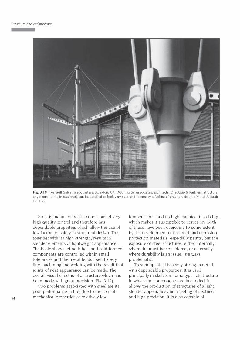
Steel is manufactured in conditions of veryhigh quality control and therefore hasdependable properties which allow the use oflow factors of safety in structural design. This,together with its high strength, results inslender elements of lightweight appearance.The basic shapes of both hot- and cold-formedcomponents are controlled within smalltolerances and the metal lends itself to veryfine machining and welding with the result thatjoints of neat appearance can be made. Theoverall visual effect is of a structure which hasbeen made with great precision (Fig. 3.19).
Two problems associated with steel are itspoor performance in fire, due to the loss ofmechanical properties at relatively low
temperatures, and its high chemical instability,which makes it susceptible to corrosion. Bothof these have been overcome to some extentby the development of fireproof and corrosionprotection materials, especially paints, but theexposure of steel structures, either internally,where fire must be considered, or externally,where durability is an issue, is alwaysproblematic.
To sum up, steel is a very strong materialwith dependable properties. It is usedprincipally in skeleton frame types of structurein which the components are hot-rolled. Itallows the production of structures of a light,slender appearance and a feeling of neatnessand high precision. It is also capable of
Structure and Architecture
34
Fig. 3.19 Renault Sales Headquarters, Swindon, UK, 1983; Foster Associates, architects; Ove Arup & Partners, structuralengineers. Joints in steelwork can be detailed to look very neat and to convey a feeling of great precision. (Photo: AlastairHunter)
producing very long span structures, andstructures of great height. The manufacturingprocess imposes certain restrictions on theforms of steel frames. Regular overall shapesproduced from straight, parallel-sidedelements are the most favoured.
3.5 Concrete
Concrete, which is a composite of stonefragments (aggregate) and cement binder, may beregarded as a kind of artificial masonry because ithas similar properties to stone and brick (highdensity, moderate compressive strength, minimaltensile strength). It is made by mixing togetherdry cement and aggregate in suitable proportionsand then adding water, which causes the cementto hydrolyse and subsequently the whole mixtureto set and harden to form a substance with stone-like qualities.
Plain, unreinforced concrete has similarproperties to masonry and so the constraintson its use are the same as those which applyto masonry, and which were outlined inSection 3.2. The most spectacular plainconcrete structures are also the earliest – themassive vaulted buildings of Roman antiquity(see Figs 7.30 to 7.32).
Concrete has one considerable advantageover stone, which is that it is available in semi-liquid form during the building process andthis has three important consequences. Firstly,it means that other materials can beincorporated into it easily to augment itsproperties. The most important of these is steelin the form of thin reinforcing bars which givethe resulting composite material (reinforcedconcrete) (Fig. 3.20) tensile and thereforebending strength as well as compressivestrength. Secondly, the availability of concretein liquid form allows it to be cast into a widevariety of shapes. Thirdly, the casting processallows very effective connections to be providedbetween elements and the resulting structuralcontinuity greatly enhances the efficiency of thestructure (see Appendix 3).
Reinforced concrete possesses tensile aswell as compressive strength and is therefore
suitable for all types of structural elementincluding those which carry bending-typeloads. It is also a reasonably strong material.Concrete can therefore be used in structuralconfigurations such as the skeleton frame forwhich a strong material is required and theresulting elements are reasonably slender. Itcan also be used to make long-span structuresand high, multi-storey structures.
Although concrete can be moulded intocomplicated shapes, relatively simple shapesare normally favoured for reasons of economyin construction (Fig. 3.21). The majority of
35
Structural materials
Fig. 3.20 In reinforced concrete, steel reinforcing bars arepositioned in locations where tensile stress occurs.
Fig. 3.21 Despite the mouldability of the material,reinforced concrete structures normally have a relativelysimple form so as to economise on construction costs. Atypical arrangement for a multi-storey framework is shown.
(a) (b)
(c) (d)
reinforced concrete structures are thereforepost-and-beam arrangements (see Section 5.2)of straight beams and columns, with simplesolid rectangular or circular cross-sections,supporting plane slabs of constant thickness.The formwork in which such structures are castis simple to make and assemble and thereforeinexpensive, and can be re-used repeatedly inthe same building. These non-form-activearrangements (see Section 4.2) are relativelyinefficient but are satisfactory where the spansare short (up to 6 m). Where longer spans arerequired more efficient ‘improved’ types ofcross-section (see Section 4.3) and profile areadopted. The range of possibilities is large dueto the mouldability of the material. Commonlyused examples are coffered slabs and taperedbeam profiles.
The mouldability of concrete also makespossible the use of complex shapes and theinherent properties of the material are suchthat practically any shape is possible.Reinforced concrete has therefore been usedfor a very wide range of structural geometries.Examples of structures in which this has beenexploited are the Willis, Faber and Dumasbuilding (see Fig. 7.37), where the mouldabilityof concrete and the level of structuralcontinuity which it makes possible were usedto produce a multi-storey structure ofirregularly curved plan with floors which
cantilevered beyond the perimeter columns,and the Lloyd’s Building, in London (Fig. 7.9),in which an exposed concrete frame was givengreat prominence and detailed to express thestructural nature of its function. The buildingsof Richard Meier (see Fig. 1.9) and PeterEisenman (see Fig. 5.18) are also examples ofstructures in which the innate properties ofreinforced concrete have been well exploited.
Sometimes the geometries which areadopted for concrete structures are selected fortheir high efficiency. Form-active shells forwhich reinforced concrete is ideally suited areexamples of this (see Fig. 1.4). The efficiency ofthese is very high and spans of 100 m andmore have been achieved with shells a fewtens of millimetres in thickness. In other casesthe high levels of structural continuity havemade possible the creation of sculpturedbuilding forms which, though they may beexpressive of architectural meanings, are notparticularly sensible from a structural point ofview. A well-known example of this is the roofof the chapel at Ronchamp (see Fig. 7.40) byLe Corbusier, in which a highly individual andinefficient structural form is executed inreinforced concrete. Another example is theVitra Design Museum by Frank Gehry (see Fig.7.41). It would have been impossible to makethese forms in any other structural material.


![MKU 2011 Prospectus[1]](https://static.documents.pub/doc/80x56/547ace69b4af9fd3158b4c61/mku-2011-prospectus1.jpg)


