30
© 2011 ANSYS, Inc. May 24, 2012 1 3-D Design Flow Automation for HFSS Jim DeLap Technical Manager [email protected]
| Date post: | 25-Apr-2018 |
| Category: |
Documents |
| Upload: | duongthuan |
| View: | 245 times |
| Download: | 1 times |

© 2011 ANSYS, Inc. May 24, 2012 1
3-D Design Flow Automation for HFSS
Jim DeLap Technical Manager
© 2011 ANSYS, Inc. May 24, 2012 2
Existing methods of defining 3D models within HFSS have been sufficient since the introduction of the product many years ago. To better align with customers’ existing product design flows, ANSYS has long had a policy of being CAD agnostic. To that end, the bi-directional CAD associativity, already available for Mechanical and Fluids designers in the ANSYS Workbench, is now accessible to Electromagnetics users as well.
Motivation

© 2011 ANSYS, Inc. May 24, 2012 3
• Existing 3D model design flow
• Example of MCAD Integration without parameterization
• Example of MCAD Integration with parameterization
• Example of MCAD Integration with parameterization AND Coupled Physics
Agenda
© 2011 ANSYS, Inc. May 24, 2012 4
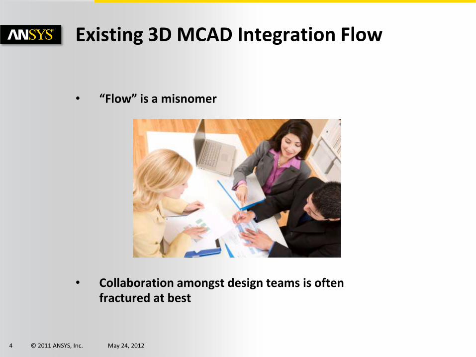
• “Flow” is a misnomer
• Collaboration amongst design teams is often fractured at best
Existing 3D MCAD Integration Flow

© 2011 ANSYS, Inc. May 24, 2012 5
Existing 3D MCAD Integration Methods
Drafting
Mechanical
Electrical
© 2011 ANSYS, Inc. May 24, 2012 6
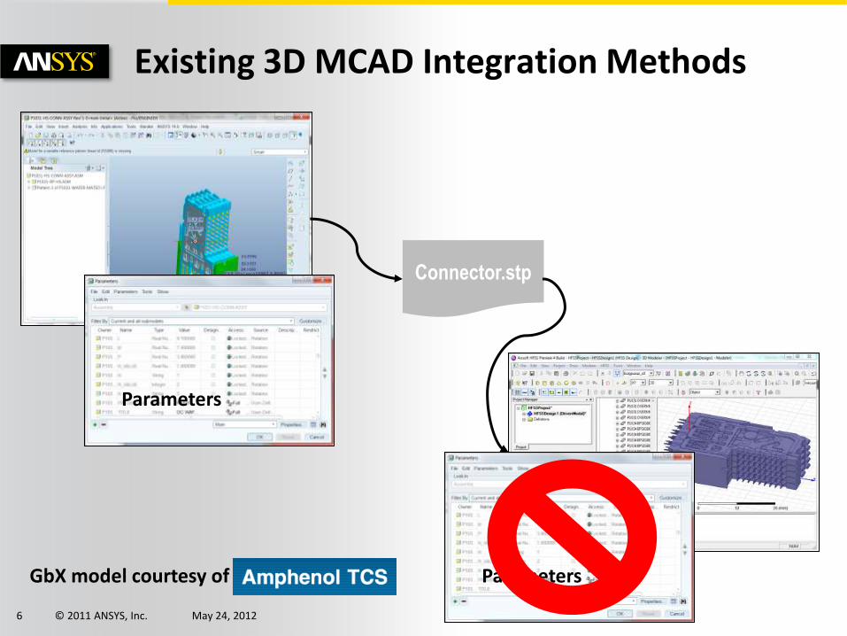
Existing 3D MCAD Integration Methods
GbX model courtesy of
Connector.stp
Parameters
Parameters

© 2011 ANSYS, Inc. May 24, 2012 7
Heritage
• ANSYS has a long history of being MCAD-agnostic for Mechanical and Fluid simulation
• Now, this capability can be applied to all the 3D Electromagnetic products as well

© 2011 ANSYS, Inc. May 24, 2012 8
• AutoCAD
• Catia v4 & v5
• Creo Elements/Direct (CoCreate)
• Creo Parametric (Pro/Engineer)
• Inventor
• JTOpen
• NX
• Sold Edge
• SolidWorks
• TeamCenter Engineering
Geometry Interface Supports…

© 2011 ANSYS, Inc. May 24, 2012 9
Examples of MCAD Integration
• Demonstrate two methodologies for using MCAD integration with HFSS
1. Integration without parameterization
• Replaces file-based model transfer
• Uses the following licenses
– HFSS (hfss_desktop, hfss_gui, hfss_solve)
– MCAD license
– ANSYS Geometry Interface license (piproe, etc.)
2. Integration with parameterization
• Allows greater model reuse and design exploration
• Uses the following licenses
– HFSS (hfss_desktop, hfss_gui, hfss_solve)
– Optimetrics (hfss_optimetrics)
– MCAD license
– ANSYS Geometry Interface license (piproe, etc.)

© 2011 ANSYS, Inc. May 24, 2012 10
MCAD Integration without Parameterization
© 2011 ANSYS, Inc. May 24, 2012 11
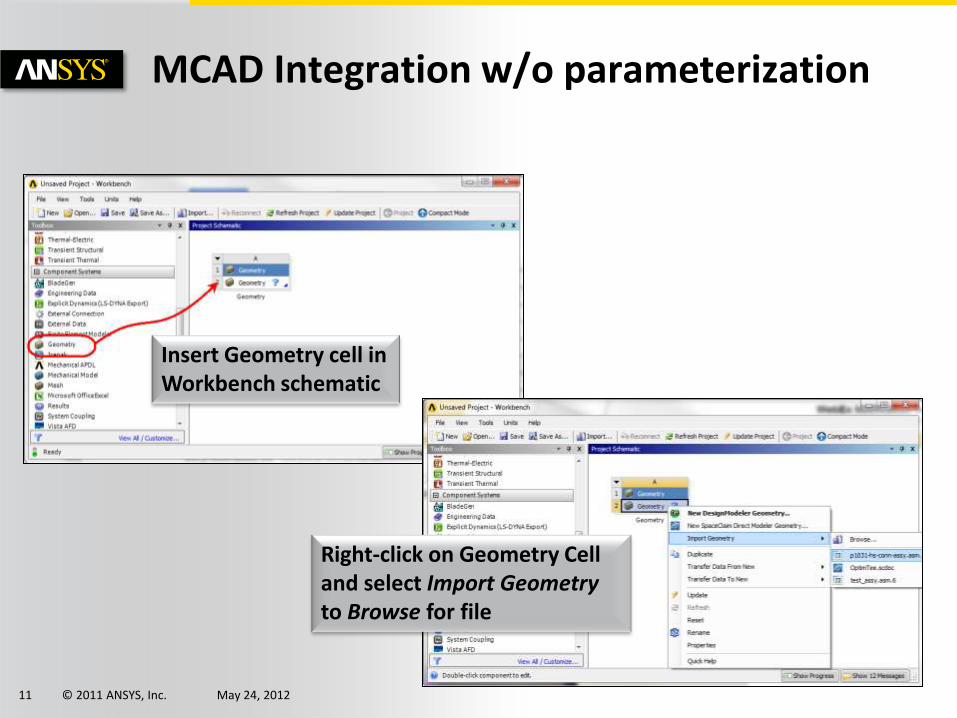
MCAD Integration w/o parameterization
Insert Geometry cell in Workbench schematic
Right-click on Geometry Cell and select Import Geometry to Browse for file

© 2011 ANSYS, Inc. May 24, 2012 12
MCAD Integration w/o parameterization
Insert HFSS component into Schematic
Click on the Geometry cell, drag it over the Geometry cell for the HFSS component and release

© 2011 ANSYS, Inc. May 24, 2012 13
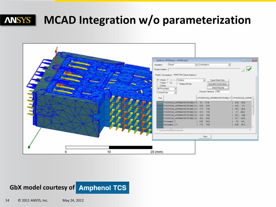
MCAD Integration w/o parameterization
Refresh Project brings in Geometry from MCAD tool
Assign materials, excitations, boundaries, setup, and run simulation GbX model courtesy of
© 2011 ANSYS, Inc. May 24, 2012 14
Put in profile and mesh display from connetor
MCAD Integration w/o parameterization
GbX model courtesy of

© 2011 ANSYS, Inc. May 24, 2012 15
MCAD Integration with Parameterization

© 2011 ANSYS, Inc. May 24, 2012 16
MCAD Integration with parameterization

© 2011 ANSYS, Inc. May 24, 2012 17
MCAD Integration with parameterization
Insert Geometry component into schematic, right-click, and select Import Geometry, and browse to the SCDM file
Click on the Geometry cell, and drag it over the Geometry cell in the HFSS component
© 2011 ANSYS, Inc. May 24, 2012 18
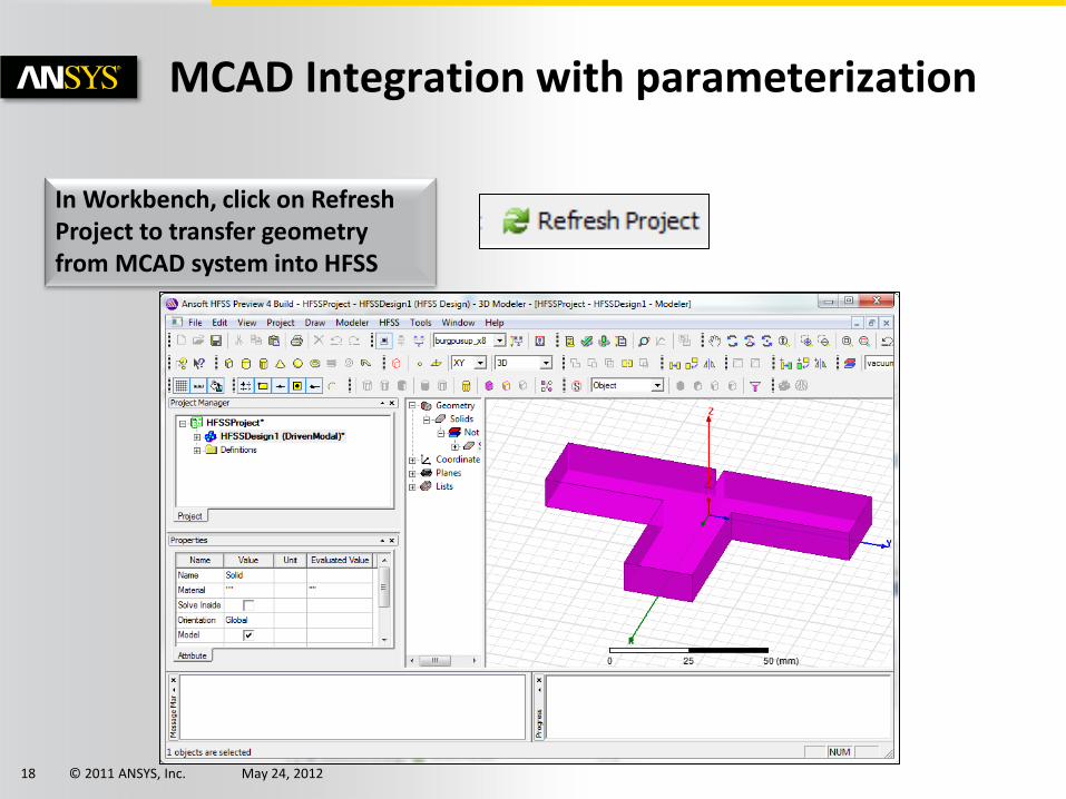
MCAD Integration with parameterization
In Workbench, click on Refresh Project to transfer geometry from MCAD system into HFSS

© 2011 ANSYS, Inc. May 24, 2012 19
MCAD Integration with parameterization
• You may need to enable the Parameters to be passed from WB into HFSS
• To do this, select the Geometry cell in the schematic, and view the properties
• The Parameters property needs to be enabled (checked)
• The Parameter Key value is a text filter to apply to the linked geometry
• Sometimes with MCAD models, there can be many variables
• One way to limit the number of variables transferred to WB, is to add a prefix to the variables in the host system

© 2011 ANSYS, Inc. May 24, 2012 20
MCAD Integration with parameterization
• Selecting the Geometry component from the model tree will enable access to parameters from the Workbench cell including the Parameters tab
• In order to perform any type of parameterization within Workbench, we need to create a WB-specific variable
• In the Value field for the offset, we will enter WBoffset, and define this as 0mm
• From here, we set up the problem as normal, assigning materials, boundaries, and excitations, as well as adding the Solution Setup

© 2011 ANSYS, Inc. May 24, 2012 21
MCAD Integration with parameterization
• In the WB Schematic, we still don’t have any parameters identified
• This would be identified by a P block linked to the HFSS project showing variables as an input, and calculations as the output
• We create an output variable to calculate the power split between the two output ports
© 2011 ANSYS, Inc. May 24, 2012 22
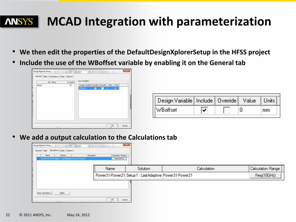
MCAD Integration with parameterization
• We then edit the properties of the DefaultDesignXplorerSetup in the HFSS project
• Include the use of the WBoffset variable by enabling it on the General tab
• We add a output calculation to the Calculations tab
© 2011 ANSYS, Inc. May 24, 2012 23
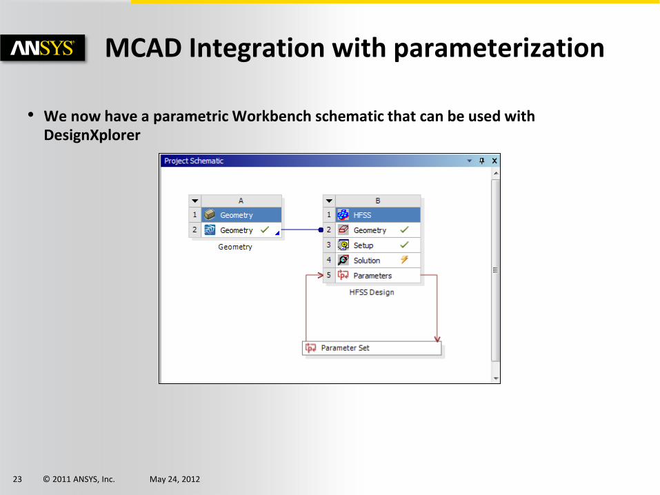
MCAD Integration with parameterization
• We now have a parametric Workbench schematic that can be used with DesignXplorer

© 2011 ANSYS, Inc. May 24, 2012 24
MCAD Integration with parameterization
• Clicking on the Parameters bar to edit the parameters and look at the outputs allows you to see the Design Points (DP) which have been solved
• You can change the value of the Parameter, P1, Update Project, and HFSS will be run to produce a new output Parameter, P2
• Running HFSS in this manner will require the MCAD license to be pulled as well as the HFSS solver license

© 2011 ANSYS, Inc. May 24, 2012 25
MCAD Integration with parameterization
• The real power of parameterization is the ability to run Design of Experiments with Goal-based Optimizations and Six-Sigma Analyses
© 2011 ANSYS, Inc. May 24, 2012 26
Bringing It All Together MCAD Integration with Coupled Physics
© 2011 ANSYS, Inc. May 24, 2012 27
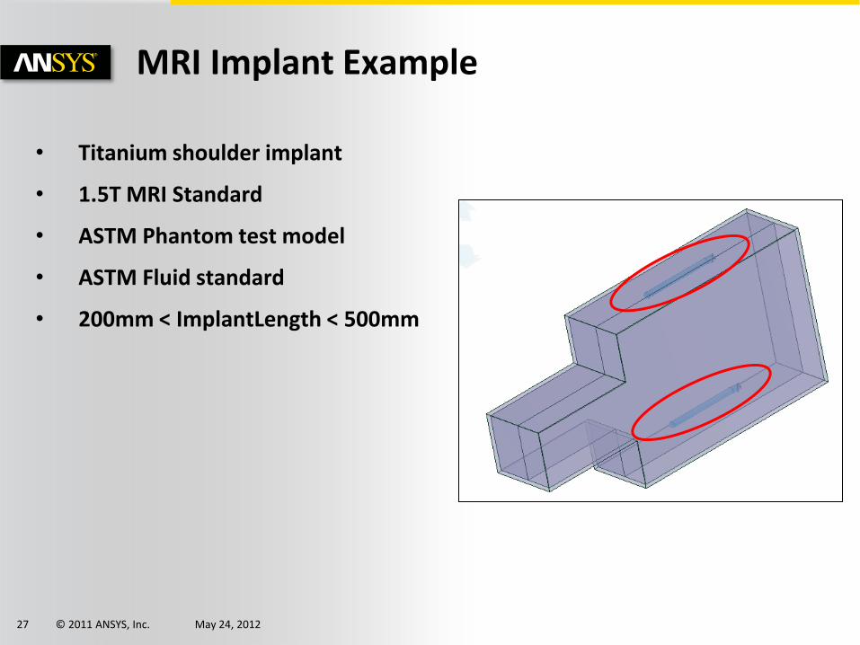
MRI Implant Example
• Titanium shoulder implant
• 1.5T MRI Standard
• ASTM Phantom test model
• ASTM Fluid standard
• 200mm < ImplantLength < 500mm

© 2011 ANSYS, Inc. May 24, 2012 28
MRI Implant Example

© 2011 ANSYS, Inc. May 24, 2012 29
MRI Implant Example

© 2011 ANSYS, Inc. May 24, 2012 30
Summary
• ANSYS CAD Integration License enables linkage to HFSS
• Eliminates geometry translation
• Enables parametric models in HFSS
• Enables non-HFSS users to drive the tool


