2
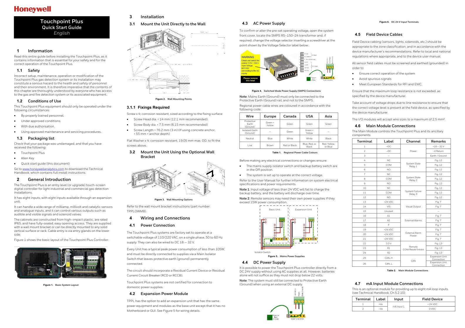
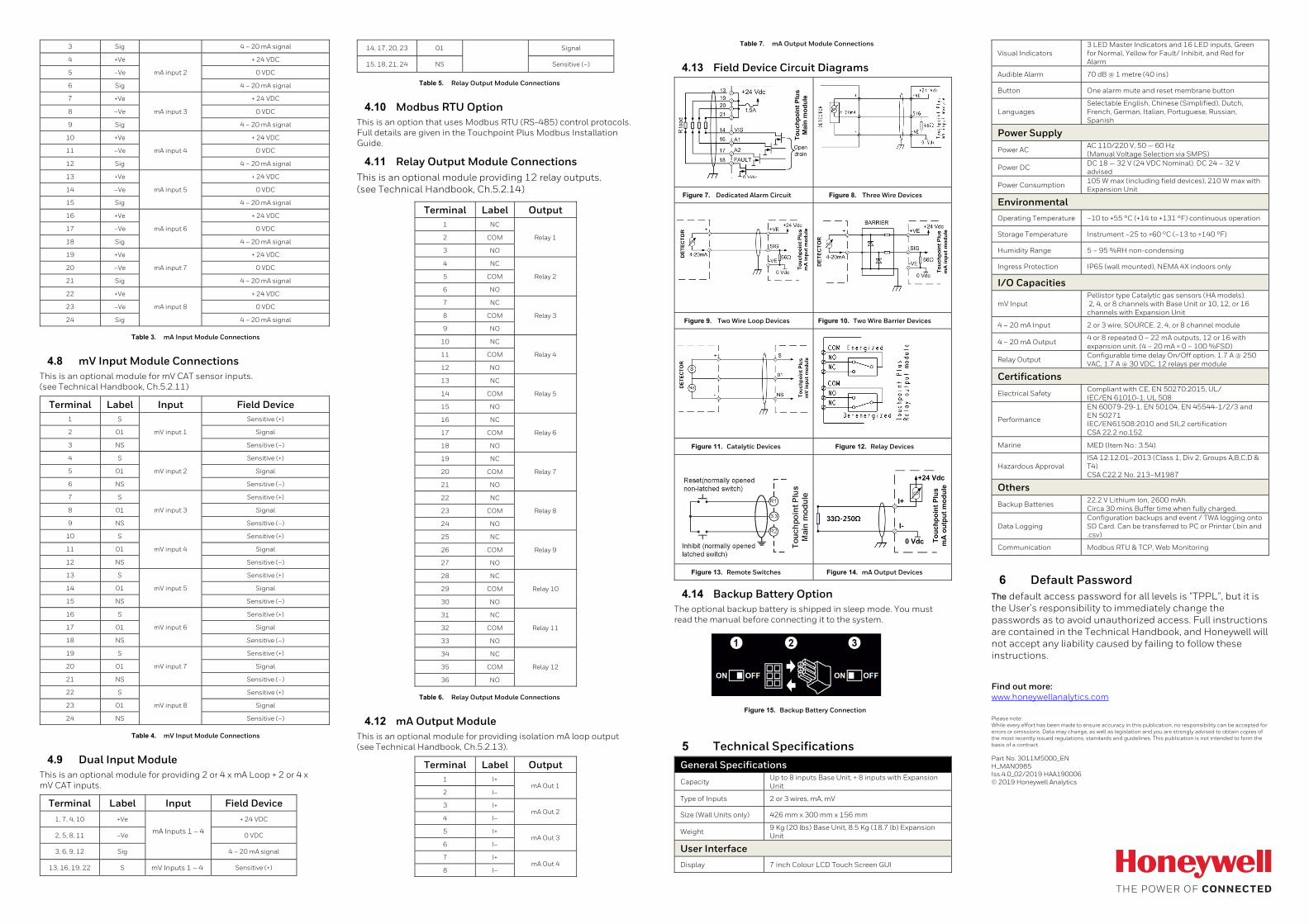
1 Information Read this entire guide before installing the Touchpoint Plus, as it contains information that is essential for your safety and for the correct operation of the Touchpoint Plus. 1.1 Safety Incorrect setup, maintenance, operation or modification of the Touchpoint Plus gas detection system or its installation may constitute a serious hazard to the health and safety of personnel and their environment. It is therefore imperative that the contents of this chapter are thoroughly understood by everyone who has access to the gas and fire detection system or its associated equipment. 1.2 Conditions of Use This Touchpoint Plus equipment should only be operated under the following circumstances: • By properly trained personnel. • Under approved conditions. • With due authorisation. • Using approved maintenance and servicing procedures. 1.3 Packaging list Check that your package was undamaged, and that you have received the following: • Touchpoint Plus • Allen Key • Quick start guide (this document) Go to www.honeywellanalytics.com to download the Technical Handbook, which contains full install instructions. 2 General Introduction The Touchpoint Plus is an entry level (or upgrade) touch-screen digital controller for light industrial and commercial gas detection installations. It has eight inputs, with eight inputs available through an expansion unit. It can handle a wide range of milliamp, millivolt and catalytic sensors and analogue inputs, and it can control various outputs such as audible and visible signals and solenoid valves. The cabinets are constructed from high–impact plastic, are rated IP65, and have fully-sealed, easy opening access. They are supplied with a wall mount bracket or can be directly mounted to any solid vertical surface or rack. Cable entry is via entry glands on the lower side. Figure 1 shows the basic layout of the Touchpoint Plus Controller: Figure 1. Basic System Layout 3 Installation 3.1 Mount the Unit Directly to the Wall Figure 2. Wall Mounting Points 3.1.1 Fixings Required Screw x 4; corrosion resistant, sized according to the fixing surface: • Screw Head dia. < 14 mm (12.1 mm recommended) • Screw Body dia. < 7.5 mm (6.15 mm recommended) • Screw Length > 76.2 mm (3 in) (If using concrete anchor, > 55 mm + anchor depth) Flat Washer x 4; corrosion resistant, 19.05 mm max. OD, to fit the screws above. 3.2 Mount the Unit Using the Optional Wall Bracket Figure 3. Wall Mounting Options Refer to the wall mount bracket instructions (part number: TPPLOWMB). 4 Wiring and Connections 4.1 Power Connection The Touchpoint Plus systems are factory set to operate at a switchable voltage of 110/220 VAC, on a single phase, 50 to 60 Hz supply. They can also be wired to DC 18 — 32 V. Every Unit has a typical peak power consumption of less than 105W, and must be directly connected to supplies via a Main Isolator Switch that leaves protective earth (ground) permanently connected. The circuit should incorporate a Residual Current Device or Residual Current Circuit Breaker (RCD or RCCB). Touchpoint Plus systems are not certified for connection to domestic power supplies. 4.2 Expansion Power Module TPPL has the option to add an expansion unit that has the same power equipment and modules as the base unit except that it has no Motherboard or GUI. See Figure 5 for wiring details. 4.3 AC Power Supply To confirm or alter the pre-set operating voltage, open the system front cover, locate the SMPS RS–150–24 transformer and, if required, change the voltage selector inserting a screwdriver at the point shown by the Voltage Selector label below: Figure 4. Switched Mode Power Supply (SMPS) Connections Note: Mains Earth (Ground) must only be connected to the Protective Earth (Ground) rail, and not to the SMPS. Regional power cable wires are coloured in accordance with the following code: Wire Europe Canada USA Asia Protective Earth (Ground) Green + Yellow Green Green Green Isolated Earth (Ground) — Green Green + Yellow — Neutral Blue White White Black Live Brown Red or Black Blue, Red, or Black Red, Yellow, or Blue Table 1. Regional Power Cable Colours Before making any electrical connections or changes ensure: • The mains supply isolator switch and backup battery switch are in the Off position. • The system is set up to operate at the correct voltage. Refer to the User Manual for further information on system electrical specifications and power requirements. Note 1: Input voltage of less than 24 VDC will fail to charge the backup battery, and the battery will discharge over time. Note 2: Remote sensors may need their own power supplies if they exceed 15W power consumption. Figure 5. Mains Power Supplies 4.4 DC Power Supply It is possible to power the Touchpoint Plus controller directly from a DC 24V supply without using AC supplies at all. However, batteries alone will not suffice as they must not drop below 22 volts. Note: The system must still be connected to Protective Earth (Ground) when using an external DC supply. Figure 6. DC 24 V Input Terminals 4.5 Field Device Cables Field Device cabling (sensors, lights, solenoids, etc.) should be appropriate to the zone classification, and in accordance with the device manufacturer’s recommendations. Refer to local and national regulations where appropriate, and to the device user manual. All sensor field cables must be screened and earthed (grounded) in order to: • Ensure correct operation of the system • Avoid spurious signals • Meet European Standards for RFI and EMC. Ensure that the maximum loop resistance is not exceeded, as specified by the device manufacturer. Take account of voltage drops due to line resistance to ensure that the correct voltage level is present at the field device, as specified by the device manufacturer. The I/O modules will accept wire sizes to a maximum of 2.5 mm². 4.6 Main Module Connections The Main Module controls the Touchpoint Plus and its ancillary components. Terminal Label Channel Remarks 1 +DC Power +18 – 32 V 2 –DC -V Return 3 — Earth / Ground 4 NC System State Relay 1 Fig. 12 5 COM Fig. 12 6 NO Fig. 12 7 NC System State Relay 2 Fig. 12 8 COM Fig. 12 9 NO Fig. 12 10 NC System Failure Relay 3 Fig. 12 11 COM Fig. 12 12 NO Fig. 12 13 +24 VDC Visual Output Fig. 7 14 VIS Fig. 7 15 Unused — 16 A1 External Alarms Fig. 7 17 A2 Fig. 7 18 F Fig. 7 19 +24 VDC External Alarm Power Fig. 7 20 +24 VDC Fig. 7 21 +24 VDC Fig. 7 22 3.3 V Remote COM/Reset/Inhibit Fig. 13 23 R1 Fig. 13 24 R2 Fig. 13 25 CAN_H CAN Expansion Unit Connection 26 CAN_L Expansion Unit Connection Table 2. Main Module Connections 4.7 mA Input Module Connections This is an optional module for providing up to eight mA loop inputs. (see Technical Handbook, Ch.5.2.10) Terminal Label Input Field Device 1 +Ve mA input 1 + 24 VDC 2 –Ve 0 VDC Touchpoint Plus Quick Start Guide English Basic Unit Expansion Unit Isolator Switch