+ All Categories
Home > Documents > 3 Leachate Recirculation in Bioreactors · Mechanism of Gas Collection ... – bacterial seeding...

3 Leachate Recirculation in Bioreactors · Mechanism of Gas Collection ... – bacterial seeding...

Date post: 07-Apr-2018
Category:
Upload: trancong
View: 223 times
Download: 4 times
Share this document with a friend
25
1 1 Leachate Recirculation and Biogas Collection Methodologies in Bioreactors E. McBean, Ph.D., P.Eng., P.E. School of Engineering University of Guelph © 2 Municipal Solid Waste Moisture Decomposed Solid Waste Bio-gas Leachate Heat INPUT OUTPUT
Transcript

1

1

Leachate Recirculation andBiogas Collection Methodologies

in Bioreactors

E. McBean, Ph.D., P.Eng., P.E.School of EngineeringUniversity of Guelph

©

2

Municipal Solid Waste

Moisture

Decomposed Solid Waste

Bio-gas

Leachate

Heat

INPUT OUTPUT

2

3

Leachate Recirculation Attributes

• Leachate quality becomes uniform over time• Traditional leachate treatment postponed• Heavy metal concentrations reduced over time• Settlement rates accelerated• Settlement enhanced• LFG production enhanced in both quality and

quantity

4

• Leachate Recirculation Concerns:– Bioreactor increases the complexity of analysis

dictating a need for better information– Instrumentation - moisture distribution,

moisture control, decomposition indicators– Increases slope stability concerns– Potential for leachate breakout

3

5

Leachate Generation

• Begins with the placement of waste anddoes not cease until well after closure

• About 50% of the moisture infiltrating alandfill is not absorbed by the waste

6

Properties Affecting HydraulicConductivity

• Leachate properties– kinematic viscosity– density

• MSW properties– moisture content– degree of biodegradation– composition– compaction– depth within the landfill– degree of processing– landfill age

4

7

Biogas Collection Issues

• Must reflect from outset, the considerablequantities of biogas which will bedeveloped

• Relying upon the collection system when itis most capable

8

Landfill Gas

• Odors/potential carcinogens• Explosion, asphyxiation and toxicity

hazards• Release of greenhouse gases• Adverse effects on local air quality

5

9

Gas Collection Effectiveness inBioreactors

• Significantly higher rates of gas production• Require significantly higher gas collection

capabilities• Not uncommon for gas trenches and wells

to accumulate liquid

10

Issues with Gas Collection

• Air intrusion through point of entry into thebioreactor - an ongoing issue

• Care needed regarding bottom/dragdowneffect on bioreactor equipment

• Must avoid providing a conduit for transferof leachate vertically through the refuse

6

11© McBean

12

Gas Collection Methodologies

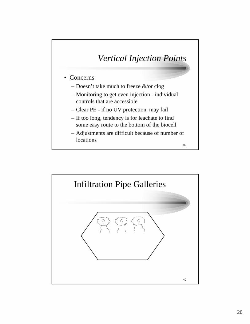
• Collection methodologies include:– Drive point wells– Drilled extraction wells– Horizontal gas collection wells

7

13

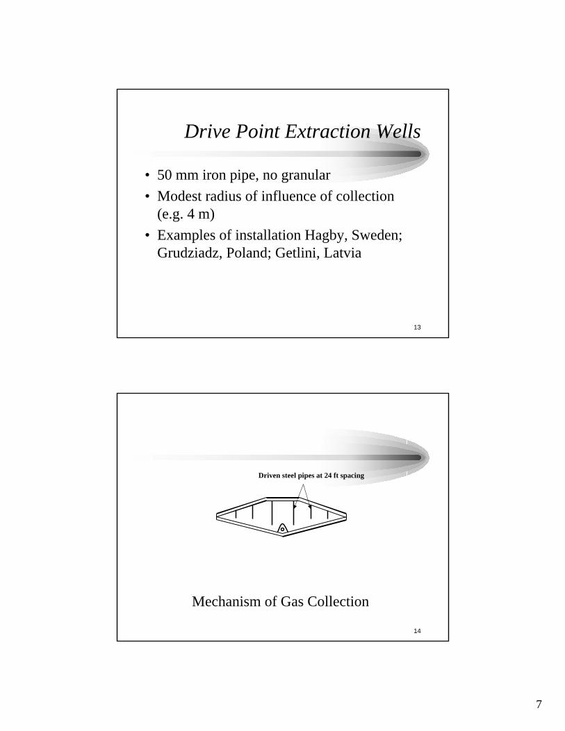
Drive Point Extraction Wells

• 50 mm iron pipe, no granular• Modest radius of influence of collection

(e.g. 4 m)• Examples of installation Hagby, Sweden;

Grudziadz, Poland; Getlini, Latvia

14

Mechanism of Gas Collection

Driven steel pipes at 24 ft spacing

8

15

Concerns with Drive PointMethodology

• Tightening required around surface to prevent air intrusion• Vertical migration opportunity for leachate• Subsidence and proximity of perforations to surface• Dragdown and possible puncture of bottom liner• Plastics “wrapping” around well column during

installation, thereby intefering with biogas collection

16

Drilled Extraction Wells

• Similar to traditional landfill gas extractionwells - drilled, surrounded by granular

• Implementation possible after placement ofwastes is completed

• Shortcircuiting of leachate beingrecirculated

9

17

Horizontal Gas Collection Wells

• Concern with ingress of fines• Can be added during development of biocell

and/or after cell virtually completed• Concern with filling with condensate and/or

recirculated leachate

18

Horizontal Gas Collection Wells

• Pipe strength and materials and maintainingof integrity

• Transmissivity of bedding system• Perforation pattern and spacing

10

19

Condensate Management inBiogas Collection System

• An absolutely major issue - surging,blockage, “gumming up”

20

• Uncertainty in gas - very moist waste(approaching field capacity) may producegas at rates that are more than double therate of production from dry wastes, all otherfactors being equal

11

21

Part II: Leachate RecirculationIssues

22

Leachate Recirculation

• Objectives– Elevate moisture levels in refuse to maximize

degradation rate– Introduce moisture, microorganisms and

nutrients– Considerations must include leachate collection

methodology to be employed

12

23

Recirculation provides

• Opportunities for pH buffering, nutrientaddition, moisture additions(optimum pH 6.8-7.2)young leachates pH<6.5

• To accelerate decomposition ( little if<20%, maximum at > 40%)

24

Purposes of MoistureIntroduction

• Leachate recirculation has long been knownto enhance biodegradation because– increases in situ moisture content accelerate

decomposition,– maintains moisture flow through the waste,– improves the distribution of microbes and nutrients in

the waste stream– organics introduction– bacterial seeding– pH buffering– nutrient content

13

25

Moisture Addition Can beAccomplished by:

• Recirculation of leachate• The addition of water• The addition of other, bulk liquids

26

Major consideration:

• Difference between bioreactors and leachaterecirculation landfills

• Bioreactors increase the complexity,dictating need for better information(moisture distribution, moisture control anddecomposition indicators)

14

27

Concerns During Recirculation,for Bioreactor Performance

• Must ensure the recirculation elements arenot entry points for air intrusion

• Evenness of injection essential for success• Odor prevention• Freezing in winter• Cost• Accessibility of the controls• Hydraulic blocking problems

28

Alternatives for LeachateRecirculation

• A number exist – surface and subsurface;retrofit as opposed to as-builts

• Most appropriate is dependent on size ofbioreactor

• Pre-cap versus post-cap

15

29

Surface Application Methods

• Constrains waste disposal operations• Nuisance odors• Health and safety concerns• Limited amount of liquid that can be

introduced• Unevenness of introduced moisture

30

Infiltration Ponds

• Many of the problems of surface applicationmethods– Odors– Spatially limited/Unevenness of moisture

introduction– Reasonable experience at this approach

16

31

32

© McBean

17

33

Vertical Injection Wells

• Examples include:– 2 inch diameter steel rods, perforated over

bottom 2 ft– 12 ft wells used by DSWA, filled with baseball-

sized granular• Individual delivery points for recirculated

leachate• Injection under pressure

34

18

35

36

19

37

38

Cross-section of Bioreactor, Latvia

150 Ft.

13

13 4.

5 Ft

.

2 Ft. of Clay

2 Ft. of Cover

Leachate Collection Pipe

Perforated Zone

2Ft.

Cross-section of Bioreactor, Latvia

Mechanism of Leachate Injection, Latvia

20

39

Vertical Injection Points

• Concerns– Doesn’t take much to freeze &/or clog– Monitoring to get even injection - individual

controls that are accessible– Clear PE - if no UV protection, may fail– If too long, tendency is for leachate to find

some easy route to the bottom of the biocell– Adjustments are difficult because of number of

locations

40

Infiltration Pipe Galleries

21

41

Infiltration Pipe Galleries

• Higher costs but are effective at deliveringhigher quantities of liquid

• Can be negatively influenced by settlement• Uncertainty regarding pipe spacing &

lengths, pipe perforation patterns andbedding materials

• Can be gravity drainage trenches

42

Horizontal Pipes Per DendriticDrainage Pattern

22

43

Dendritic Pattern for Leachate Recirculation

Bioreactor

44

Horizontal Injection Pipes inDendritic Pattern

• Better distributional pattern but harder tocontrol where the recirculated leachate isactually entering the refuse

• Greater tendency for failure post-closurethan for horizontal pipe galleries

23

45

Alternatives for Leachate RecirculationMethods to Energy Cells

• Surface spray application systems– spray irrigation at the waste tipping face– Tanker truck

• Drip irrigation• Infiltration ponds• Individual vertical injection wells• Horizontal injection galleries• Horizontal injection pipes in dendritic pattern

46

Capillary Wicking Layers

• Applied as a daily cover (to overcome thepotential for channeled flow of leachatethrough the waste)

• Improves overall moisture dispersal• Examples e.g. pulp sludges

24

47

• Some bioreactors are highly stratified• High lateral hydraulic conductivity as

compared to vertical conductivity• Influenced by degree of waste compaction

48

The Leachate RecirculationOperations Plan should include

• Both application and rest periods• a monitoring plan which includes recording,

precipitation, application rate, total leachateapplied

25

49

Elapsed Time for Generation of LFG -Effect ofBioreactor Acceleration

5.8125Time to get 95 % ofLFG generated

1.328.8Time to get 50% ofLFG generated

BioreactorLandfilling (years)

ConventionalLandfilling (years)

50

• Questions?


Recommended