10
3-Phase Inverter Motor Drive Analysis 5 Series MSO Option 5-IMDA Application Datasheet www.tek.com 1

3-Phase Inverter Motor Drive Analysis5 Series MSO Option 5-IMDA Application Datasheet
www.tek.com 1
Measurements and analysis on three-phase power systems are inherentlymore complex than on single-phase systems. Although oscilloscopes cancapture voltage and current waveforms with high sample rates, furthercalculations are required to produce key power measurements from thedata. Power converters based on Pulse Width Modulation (PWM), such asvariable-frequency motor drives, further complicate measurements sincefiltering and triggering on PWM signals are challenging. Yet for mostvalidation and troubleshooting, understandably their oscilloscope is theinstrument of choice for designers. Special software, designed to automatepower analysis on inverters, motors, and drives, greatly simplifies importantthree-phase power measurements on PWM systems and can helpengineers get faster insights into their designs. The Inverter Motor DriveAnalysis (IMDA) solution from Tektronix helps engineers design better andmore efficient three-phase motor drive systems, taking full advantage of theadvanced user interface, six or eight analog input channels, and ‘High Res’mode (16 bits) on the 5 Series MSO. The IMDA solution provides fast,accurate, and repeatable results for electrical measurements on industrialmotors and drive systems for AC induction motors, permanent magnetsynchronous motors (PMSM), and brushless DC (BLDC) motors. It can beconfigured to measure DC to three-phase AC converters, such as thoseused in the electric vehicles.
Key features and specifications
Accurately analyze three-phase PWM signals used to drive ACinduction, BLDC, and PMSM motors.
Unique oscilloscope based phasor diagrams indicate VRMS, IRMS, VMAG,IMAG, and phase relationships at a glance for the configured wiringpairs.
Debug motor drive designs by viewing the drive input/output voltageand current signals in the time domain simultaneously with the phasordiagram.
Three-phase Autoset feature configures the oscilloscope for optimalhorizontal, vertical, trigger, and acquisition parameters for acquiringthree-phase signals.
Measures harmonics per the IEEE-519 standard or using custom limits.
Measures drive system efficiency using the 2V2I (two wattmeter)method.
Quickly add and configure measurements through the intuitive dragand drop interface on the 5 Series MSO.
Analyze Inverter and Automotive three-phase designs for DC-ACtopology.
Supports 1-Phase-2Wire (1V1I) and 1-Phase-3Wire (2V2I) under theAC-AC Industrial configuration.
Measurement overviewThree-phase power converters such as variable frequency drives require arange of measurements during the design process. The Inverters, Motors,and Drives Analysis package for the 5 Series MSO automates key electricalmeasurements which are grouped into three categories:
Input analysis
Output analysis
Ripple analysis
Each of these sections include key measurements which are critical to amotor design.
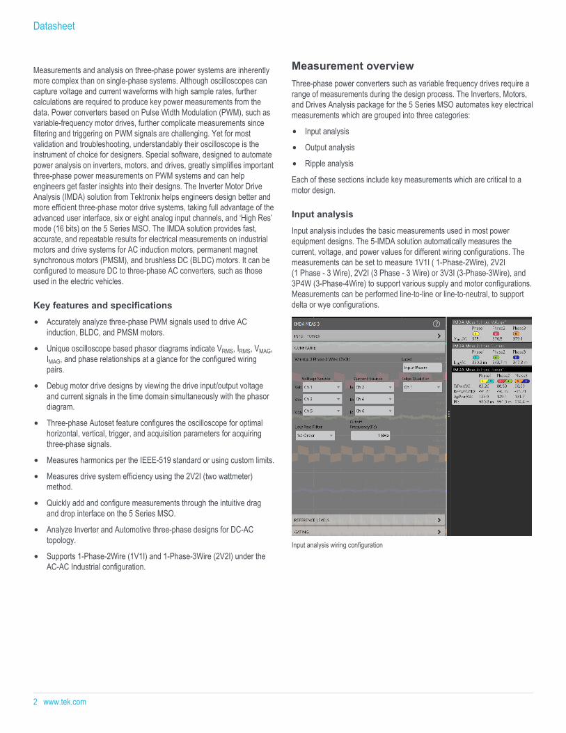
Input analysis
Input analysis includes the basic measurements used in most powerequipment designs. The 5-IMDA solution automatically measures thecurrent, voltage, and power values for different wiring configurations. Themeasurements can be set to measure 1V1I ( 1-Phase-2Wire), 2V2I(1 Phase - 3 Wire), 2V2I (3 Phase - 3 Wire) or 3V3I (3-Phase-3Wire), and3P4W (3-Phase-4Wire) to support various supply and motor configurations.Measurements can be performed line-to-line or line-to-neutral, to supportdelta or wye configurations.
Input analysis wiring configuration
Datasheet
2 www.tek.com

Harmonics
Power waveforms are rarely textbook sinusoids. Harmonics measurementsbreak down non-sinusoidal voltage or current waveforms into theirsinusoidal components, indicating the frequency and amplitude for eachcomponent.
Harmonics analysis can be performed up to 200th harmonic order. Themaximum harmonic order can be set to suit your needs by specifying therange in the measurement configuration. THD-F, THD-R and fundamentalvalues are measured for each phase. Measurements can be evaluatedagainst the IEEE-519 or IEC 61000 3-2 standard, or custom limits. Testresults can be recorded in a detailed report indicating pass/fail status.
Compare harmonics measurements against industry standards or custom limits
Power quality
This group provides critical three-phase power measurements including:frequency and RMS magnitudes of voltage and current, crest factors ofvoltage and current, PWM frequency, true power, reactive power, apparentpower, power factor, and phase angle for each phase.
Voltage and current vectors can be displayed on a phasor diagram so youcan quickly judge phase shift for each phase and the balance amongphases. Each vector is represented by an RMS value and phase iscomputed using the DFT method.
Easily configure the settings to get insight into the power quality
3-Phase Inverter Motor Drive Analysis
www.tek.com 3

Output analysis
This group of measurements can help calculate the overall performance ofthe motor drive system.
Efficiency
Efficiency measures the ratio of the output power to input power forrespective input and output V and I pairs. By using the 2V2I method, three-phase efficiency may be measured using eight oscilloscope channels(2 Voltage and 2 Current sources on the input side and 2 Voltage and2 Current sources on the output side). The solution calculates efficiency ateach phase and the total (average) efficiency of the system.
Configure wiring and filters to perform efficiency measurements for an Industrial motor
Configure wiring and filters to perform efficiency measurements for a DC-AC topology
Datasheet
4 www.tek.com

Get complete insight into the overall system efficiency
Phasor diagram
The measurement displays the magnitude and phase angle betweenVoltage(V) and Current(I) vectors in a phasor plot. The V and I vectorsdepend on the wiring configuration.
Easily configure the voltage and current inputs to display phasor diagrams
3-Phase Inverter Motor Drive Analysis
www.tek.com 5

Unique scope based phasor diagram feature provides the relation between the voltage and current vectors
Ripple analysis
Ripple is defined as the residual AC voltage on a constant DC component(offset). Typically, the ripple component is often small in magnitude relativeto the DC component.
The solution measures two types of ripple:
Line ripple
Switching ripple
Line ripple: The line ripple measures the RMS at the configured line ripplefrequency and the peak-to-peak value of the time domain waveform for theconfigured phases.
Switching ripple: The switching ripple measures the RMS at theconfigured switching ripple frequency and the peak to peak value of thetime domain waveform for the configured phases.
Ripple analysis configuration can be set to look into line and switching ripple
Datasheet
6 www.tek.com

Detailed ripple analysis being carried out on all three-phases
3-Phase Inverter Motor Drive Analysis
www.tek.com 7

Report generationThe 5-IMDA software simplifies data collection, archiving, documentation ofyour design, and development process. It supports the report generation inMHT, PDF or CSV formats with pass/fail results for easy analysis.
A sample IMDA test report file with summary, details, and corresponding images
Datasheet
8 www.tek.com

SpecificationsWiring Configuration 1V1I (1-Phase-2Wire), 2V2I (1 Phase - 3 Wire), 2V2I (3 Phase - 3 Wire), 3V3I (3-Phase-3Wire), and 3P4W (3-Phase-4Wire)
L-L to L-N Conversion Applicable for 3 Phase-3 Wire (3V3I) 1
Input Analysis Power Quality, Harmonics 2, Input Voltage, Input Current and Input Power
Ripple Analysis Line ripple, Switching ripple (for Industrial), and Ripple (for Automotive)
Output Analysis Efficiency 3, Phasor Diagram
Three-phase Autoset For all measurements
Plots Phasor diagram and harmonics bar graph 4
Report MHT and PDF format, Data export to CSV format
Degauss/Deskew (static) Automatic detection of probes, Auto Zero. User can deskew voltage and current probes, degauss the current probe from themenus for each channel
Source support Live analog signals, reference waveforms, and math waveforms
1 For 3 Phase-4 Wire (3V3I) the connection is always Line to Neutral and for 3 Phase-3 Wire (2V2I), it is Line to Line.
2 Supports Custom limits
3 For 2V2I wiring
4 Range filter as part of measurement configuration.
3-Phase Inverter Motor Drive Analysis
www.tek.com 9

Ordering information
ModelsProduct Options Supported instruments Bandwidth availableNew instrument order option 5-IMDA 5 Series MSO (MSO56, MSO58) 350 MHz
500 MHz
1 GHz
2 GHz
Product upgrade option SUP5-IMDA 5 Series MSO (MSO56, MSO58)Floating license SUP5-IMDA-FL 5 Series MSO (MSO56, MSO58)
Recommended probesProbe model Description QuantityTCP0030A Current Probes 3 for 3V3I wiring 5
THDP0200 or TMDP0200 High Voltage Differential Probes 3 for 3V3I wiring 5
Tektronix is registered to ISO 9001 and ISO 14001 by SRI Quality System Registrar.
Product(s) complies with IEEE Standard 488.1-1987, RS-232-C, and with Tektronix Standard Codes and Formats.
Product Area Assessed: The planning, design/development and manufacture of electronic Test and Measurement instruments.
5 For performing efficiency measurement, four quantities are required.
Datasheet
ASEAN / Australasia (65) 6356 3900 Austria 00800 2255 4835* Balkans, Israel, South Africa and other ISE Countries +41 52 675 3777 Belgium 00800 2255 4835* Brazil +55 (11) 3759 7627 Canada 1 800 833 9200 Central East Europe and the Baltics +41 52 675 3777 Central Europe & Greece +41 52 675 3777 Denmark +45 80 88 1401 Finland +41 52 675 3777 France 00800 2255 4835* Germany 00800 2255 4835*Hong Kong 400 820 5835 India 000 800 650 1835 Italy 00800 2255 4835*Japan 81 (3) 6714 3086 Luxembourg +41 52 675 3777 Mexico, Central/South America & Caribbean 52 (55) 56 04 50 90 Middle East, Asia, and North Africa +41 52 675 3777 The Netherlands 00800 2255 4835* Norway 800 16098 People's Republic of China 400 820 5835 Poland +41 52 675 3777 Portugal 80 08 12370 Republic of Korea +822 6917 5084, 822 6917 5080 Russia & CIS +7 (495) 6647564 South Africa +41 52 675 3777 Spain 00800 2255 4835* Sweden 00800 2255 4835* Switzerland 00800 2255 4835*Taiwan 886 (2) 2656 6688 United Kingdom & Ireland 00800 2255 4835* USA 1 800 833 9200
* European toll-free number. If not accessible, call: +41 52 675 3777
For Further Information. Tektronix maintains a comprehensive, constantly expanding collection of application notes, technical briefs and other resources to help engineers working on the cutting edge of technology. Please visit www.tek.com.
Copyright © Tektronix, Inc. All rights reserved. Tektronix products are covered by U.S. and foreign patents, issued and pending. Information in this publication supersedes that in all previously published material. Specification andprice change privileges reserved. TEKTRONIX and TEK are registered trademarks of Tektronix, Inc. All other trade names referenced are the service marks, trademarks, or registered trademarks of their respective companies.
21 Apr 2020 48W-61649-1
www.tek.com


