Annual Report 2014-2015 50 3. RESEARCH SUPPORT FACILITIES 3.1 SUPPORT LABORATORIES 3.1.1 High vacuum laboratory Chandra Pal Maurya, M. Archunan, A.Kothari, P.Barua, A. Mandal High vacuum laboratory is primarily responsible for maintaining vacuum and vacuum systems in most of the beamlines and experimental facilities. It provides support to different labs and users in vacuum related problems. As Vacuum lab is looking after large number of facilities and components, so the devices like vacuum pumps, gauges and their control systems are monitored regularly. Controllers for vacuum interlocking for turbo pumping systems, operating beam line valves and Faraday cup etc. have been designed and fabricated for use in different facilities. Consumables for vacuum components are centrally purchased and issued to different labs and users when required. Vacuum lab is also involved in the installation and commissioning of various beamlines, experimental and accelerator facilities at IUAC. At present installation of High Current Injector [HCI] components is in progress and the high voltage platform of HCI has been installed along with on-board beamline components. 3.1.1.1 High Current Injector Installation Chandra Pal, M. Archunan, Ashok Kothari, P. Barua, Yaduvansh Mathur, G. Rodrigues, Rajeev Ahuja, Deepak Kumar Munda, Kundan Singh, S.K. Suman, Mukesh Kumar, Rajkumar, A. Mandal The HCI will feed high current ion beam to superconducting LINAC modules for further acceleration. The PKDELIS ECR source and some of the LEBT components will be placed on 100 kV platform. The high voltage platform has been designed, fabricated and installed in beam hall 3. The ECR source and the magnet, beam optical and diagnostic components with required electronic and control system has been installed on the HV platform. The control system for running the source and other devices are VME based and the operation of all the devices has been tested from a remote location. A picture of the installed components is shown in figure 3.1.1. Installation also involves the development and fabrication of many components. Details of the same are given below:- 1. Support Stands and Fixtures: The basic supporting structure for mounting different components are made from aluminium profiles, which Fig. 3.1.1 HCI High Voltage Platform with ECR and LEBT Components
Transcript
Annual Report 2014-2015
50
3. RESEARCH SUPPORT FACILITIES
3.1 SUPPORT LABORATORIES
3.1.1 High vacuum laboratory
Chandra Pal Maurya, M. Archunan, A.Kothari, P.Barua, A. Mandal
High vacuum laboratory is primarily responsible for maintaining vacuum and vacuum systems in most of the beamlines and experimental facilities. It provides support to different labs and users in vacuum related problems. As Vacuum lab is looking after large number of facilities and components, so the devices like vacuum pumps, gauges and their control systems are monitored regularly. Controllers for vacuum interlocking for turbo pumping systems, operating beam line valves and Faraday cup etc. have been designed and fabricated for use in different facilities. Consumables for vacuum components are centrally purchased and issued to different labs and users when required. Vacuum lab is also involved in the installation and commissioning of various beamlines, experimental and accelerator facilities at IUAC. At present installation of High Current Injector [HCI] components is in progress and the high voltage platform of HCI has been installed along with on-board beamline components.
3.1.1.1 High Current Injector Installation
Chandra Pal, M. Archunan, Ashok Kothari, P. Barua, Yaduvansh Mathur, G. Rodrigues, Rajeev Ahuja, Deepak Kumar Munda, Kundan Singh, S.K. Suman, Mukesh Kumar, Rajkumar, A. Mandal
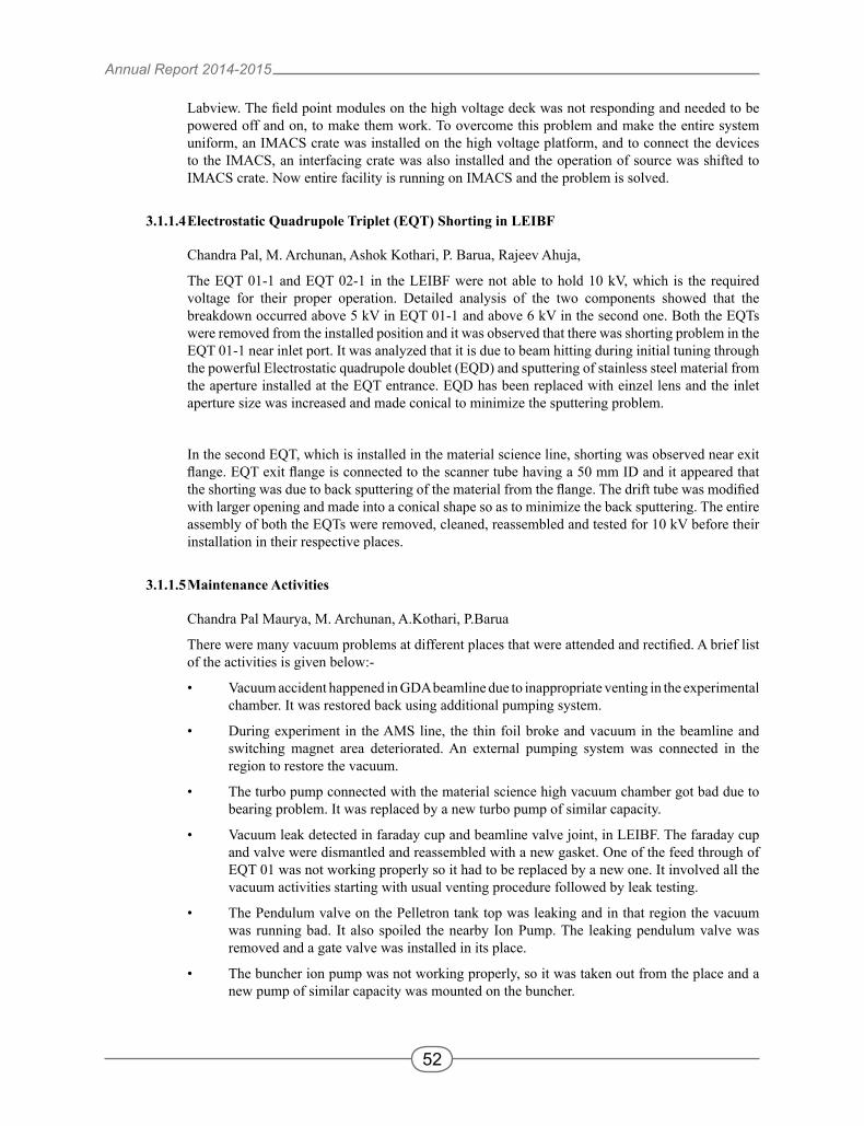
The HCI will feed high current ion beam to superconducting LINAC modules for further acceleration. The PKDELIS ECR source and some of the LEBT components will be placed on 100 kV platform. The high voltage platform has been designed, fabricated and installed in beam hall 3. The ECR source and the magnet, beam optical and diagnostic components with required electronic and control system has been installed on the HV platform. The control system for running the source and other devices are VME based and the operation of all the devices has been tested from a remote location. A picture of the installed components is shown in figure 3.1.1. Installation also involves the development and fabrication of many components. Details of the same are given below:-
1. Support Stands and Fixtures: The basic supporting structure for mounting different components are made from aluminium profiles, which Fig. 3.1.1 HCI High Voltage Platform with ECR and LEBT Components
Annual Report 2014-2015
51
are machined, assembled and erected after studying the load distribution, space and installation complexities of all the components. Installation and alignment fixtures were designed and fabricated for ECR source and Extraction system. Alignment and installation fixtures for ECR source, extraction system and electrostatic quadrupole doublet were designed and fabricated for the installation.
2. Compact Diagnostic Box: Design and fabrication of a compact diagnostic system, which includes a double slit, faraday cup, BPM and a 6” CF port for turbo pump, was done. Slit and other diagnostic components were procured from NEC and assembled in the new diagnostic box and the complete assembly has been installed and aligned.
3. Control system and Beamline device controllers: The control system for HCI is VME based and all the device controllers communicate to VME system through interface crate. The Interfacing Crate was designed and fabricated for HCI high voltage platform components. It has three IO cards, three ADC cards and two DAC cards. All the devices are connected from the back panel and front panel connects to the VME crate. Individual device controllers for faraday cup and beamline valves were also designed and fabricated.
4. Layout and Installation: Layout of the HV platform components was designed as per beam optics positions and available space on the platform. The height of the beam axis in the beam hall is 1.8 m and has been referenced from analyzer magnet of vault I. The beamline route has been marked on the beam hall floor for installation reference. The PKDELIS ECR source, magnet and other low energy beam transport components have been installed and aligned on the HV platform within 0.5 mm. First the magnet was aligned with the beamline, marked on the floor. After that the ECR source and other components were installed and aligned.
3.1.1.2 Installation of capacitive pick-up devices for LINAC operation
Chandra Pal, M. Archunan, Ashok Kothari, P. Barua
Capacitive pickup is used for beam diagnostic purpose required for the operation of LINAC. So, the capacitive pickup devices were installed at three locations, i.e. one at the entry of LINAC I, second at the exit of LINAC III and third at the entry of Re-buncher. The installation of these devices required venting the relevant area for their installation and alignment. Since, the phase detectors are not required along with these devices, all the three phase detectors were removed and these devices were installed and aligned with beam axis. Installation was carried out during LINAC maintenance. The diagnostic box at LINAC III exit has a flange mountable Faraday cup. As this was not working properly, it was replaced by a NEC Faraday cup placed before the diagnostic box. The BPM - Faraday cup assembly was aligned with beam axis within an accuracy of 0.5 mm. After-wards the relevant area were closed and were connected with beamline after vacuum and leak testing.
3.1.1.3LEIBFECRsourcecontrolsystemmodification
Chandra Pal, M. Archunan, P. Barua
The control system of the ECR source (installed on high voltage deck) and einzel lens was based on field point system in the low energy ion beam facility [LEIBF]. All other devices are controlled through Indigenous measurement and control system (IMACS). The IMACS is operated through Pelletron controlling software (Pelcon). The controlling software for the ECR and einzel lens is
Annual Report 2014-2015
52
Labview. The field point modules on the high voltage deck was not responding and needed to be powered off and on, to make them work. To overcome this problem and make the entire system uniform, an IMACS crate was installed on the high voltage platform, and to connect the devices to the IMACS, an interfacing crate was also installed and the operation of source was shifted to IMACS crate. Now entire facility is running on IMACS and the problem is solved.
3.1.1.4 Electrostatic Quadrupole Triplet (EQT) Shorting in LEIBF
Chandra Pal, M. Archunan, Ashok Kothari, P. Barua, Rajeev Ahuja,
The EQT 01-1 and EQT 02-1 in the LEIBF were not able to hold 10 kV, which is the required voltage for their proper operation. Detailed analysis of the two components showed that the breakdown occurred above 5 kV in EQT 01-1 and above 6 kV in the second one. Both the EQTs were removed from the installed position and it was observed that there was shorting problem in the EQT 01-1 near inlet port. It was analyzed that it is due to beam hitting during initial tuning through the powerful Electrostatic quadrupole doublet (EQD) and sputtering of stainless steel material from the aperture installed at the EQT entrance. EQD has been replaced with einzel lens and the inlet aperture size was increased and made conical to minimize the sputtering problem.
In the second EQT, which is installed in the material science line, shorting was observed near exit flange. EQT exit flange is connected to the scanner tube having a 50 mm ID and it appeared that the shorting was due to back sputtering of the material from the flange. The drift tube was modified with larger opening and made into a conical shape so as to minimize the back sputtering. The entire assembly of both the EQTs were removed, cleaned, reassembled and tested for 10 kV before their installation in their respective places.
3.1.1.5 Maintenance Activities
Chandra Pal Maurya, M. Archunan, A.Kothari, P.Barua
There were many vacuum problems at different places that were attended and rectified. A brief list of the activities is given below:-
• Vacuum accident happened in GDA beamline due to inappropriate venting in the experimental chamber. It was restored back using additional pumping system.
• During experiment in the AMS line, the thin foil broke and vacuum in the beamline and switching magnet area deteriorated. An external pumping system was connected in the region to restore the vacuum.
• The turbo pump connected with the material science high vacuum chamber got bad due to bearing problem. It was replaced by a new turbo pump of similar capacity.
• Vacuum leak detected in faraday cup and beamline valve joint, in LEIBF. The faraday cup and valve were dismantled and reassembled with a new gasket. One of the feed through of EQT 01 was not working properly so it had to be replaced by a new one. It involved all the vacuum activities starting with usual venting procedure followed by leak testing.
• The Pendulum valve on the Pelletron tank top was leaking and in that region the vacuum was running bad. It also spoiled the nearby Ion Pump. The leaking pendulum valve was removed and a gate valve was installed in its place.
• The buncher ion pump was not working properly, so it was taken out from the place and a new pump of similar capacity was mounted on the buncher.
Annual Report 2014-2015
53
3.1.2 Beam Transport System
S.K.Suman, Mukesh Kumar, Rajesh Kumar, A.Mandal
Beam transport system (BTS) laboratory is primarily responsible for regular upkeep and maintenance of the beam transport system instruments of different accelerator facilities at IUAC. Power supplies and magnets of different accelerator facilities are maintained regularly to ensure proper beam dynamics and best performance in terms of stability during long term operations. Besides the maintenance, BTS laboratory also involved (in collaboration with other groups) in development of equipments for accelerator augmentation and beam diagnostics, high power RF amplifiers, low level RF electronics (LLRF) and superconducting magnets. Details of development and maintenance activities related to beam transport are summarized below. (Developments related to HCI are described in section 2.2.7).
3.1.2.1 Magnetic Beam Scanner Power Supply Development.
Scanning magnets are used in material science beam line for ion irradiation experiments with ion beam. To scan the beam in a paintbrush pattern on targets these magnets are fed with current regulated triangular wave having no cross over distortion and non-linearity. Scanning magnet power supplies developed in 1995 are being used in beamline in BH-I. The performance of these power supplies have been deteriorated over time due to ageing of the components. To replace these, two new power supplies are being developed using improved technique based on a linear bipolar transconductance amplifier. To have “crossover-distortion free output" the output stage is push-pull, biased in class-AB mode. Two separate amplifiers will be developed for X and Y scanners, delivering programmable current regulated triangular wave of 0 to ±10A for X-axis at 50Hz and for Y-axis at at 0.5Hz. The construction of the scanner power supply is in advanced stage and is proceeding according to the scheduled plan. Electronic circuit boards have been assembled and assembly of power supply is in progress.
3.1.2.2 Beam Transport System Maintenance
Power supplies and magnets of all the facilities like Pelletron, LINAC, HIRA, HYRA and LEIBF, NIBF are regularly maintained during “scheduled maintenance period” to avoid failures during the beam time and also to ensure the stability of magnetic field within the limit. Approximately 200 instruments of 16 types which includes, magnet power supplies, CAMAC based control modules, magnetic field measuring instruments, beam line switchers etc are in round the clock operation and are being maintained by this group. Brief description about the maintenance is described below.
Scheduled Preventive Maintenance
To avoid failures during beam time and also to ensure the best performance in terms of stability, schedule maintenance of magnets, power supplies and other instruments has been done carefully and thoroughly twice this year. Some routine tasks carried out during the maintenance are:
• Dirt cleaning while checking for loose connections, hot spots corrosion and water leak: Compressed air blows and dirt cleaning solvents are used to keep all the power supplies and magnets clean. This reduces leakage currents, improves heat dissipation and hence avoids the unpredictable drifts
• Cleaning of cooling water paths of power supplies and magnets: To remove cuprous oxide
Annual Report 2014-2015
54
from the inner walls of the magnet coils and water hoses, sulphamic acid (moderately strong acid) is circulated through water cooling paths once every year. This minimizes leakage currents to ground and also helps to maintain proper water flows by removing partial blockages due to the scaling.
• Remote control operation: Data read-write and on-off commands are checked thoroughly for any malfunctioning.
• Safety interlocks: During scheduled maintenance safety interlock are falsely generated and tested to ensure the safety during abnormal conditions.
• Full power test: Full power test is conducted after finishing all servicing procedures to guarantee proper operation and to monitor temperature rise and hot-spots in power supply and magnet.
Breakdown Maintenance
Power supply failures during beam operations are considered as breakdowns. During this year, there were only few occasions when power supply problems caused the suspension of beam operation. The most frequent causes for power supply operation interruption were because of external factors such as over temperature because of low water flows, input mains power fluctuations and remote control failures. In most of the cases the power supplies were recovered immediately after rectifying the cause.
3.1.3 Detector Laboratory
Akhil Jhingan
Detector Laboratory at IUAC provides experimental support to various users in setting up charged particle detectors and readout electronics. New detectors and electronics have been designed and developed, and are used in various user experiments in HIRA, HYRA, GPSC and NAND. Detector lab provided training on experimental activities for Scientist Trainees, JRF, M.Tech, B.Sc and M.Sc students.
A. Jhingan, Gurpreet Kaur1, N. Saneesh, R. Dubey, T. Banerjee, R. Mahajan1, M. Thakur1, P. Sharma1, B. R. Behera1, P. Sugathan
1Department of Physics, Punjab University, Chandigarh
A detector set up for performing quasi-elastic scattering and fission angular distribution experiments was developed and commissioned in GPSC. Currently the detector system has 13 hybrid telescopes. Each telescope has an axial field gas ionization chamber, followed by a Silicon detector. Entrance window is 0.9 mm Mylar. Gas detector is operated at ~ 90 mbar Iso-Butane. Four telescopes were mounted in a ring at 170 degree, six were mounted on an arc at 20 degree pitch and were placed 140 degree onwards on one arm of GPSC. Three telescopes were placed at 12 degree pitch centered at 45 degree on the opposite arm. All telescopes were placed at a distance of 25 cm from the target with an opening of 7 mm diameter. Custom electronics were developed for signal processing of this setup. Charge sensitive preamplifiers were fabricated which were placed inside GPSC. The signals were driven by differential driver units, using shielded twisted pair cables to NIM Mesytec shaping amplifier units in data room. The system was thoroughly tested offline with radioactive sources and used for performing quasi-elastic scattering and fission angular distribution experiments using Pelletron beams.
Annual Report 2014-2015
55
3.1.3.2 MWPC for mass distribution experiments in GPSC/NAND
N. Saneesh, A. Jhingan, P. Sugathan
Two large area position sensitive MWPC have been developed for performing mass distribution and neutron multiplicity experiments in GPSC/NAND. The MWPCs are identical to the two earlier MWPCs being used for mass-distribution experiments in GPSC. The detectors have four electrode geometry with an active area of 20 cm x 10cm. The first electrode is cathode followed by X-position, anode and Y-position electrode. All electrodes are made using 20 mm gold plated tungsten wires at 1.27 mm pitch. Inter electrode separation is 3.2 mm. It is planned to use all four MWPC in NAND, two in the back hemisphere and two in front hemisphere so as to improve upon the statistics and coincidence efficiency in neutron multiplicity experiment. The setup can be used to carry out transfer induced fission/surrogate fission reaction experiments.
3.1.3.3 MWPC with discrete delay line position readout
A pair of position sensitive MWPC have been fabricated with delay line position readouts developed using discrete surface mount components in place of commercially available delay line IC. The detectors have a three electrode geometry: cathode sandwiched between two position sensitive electrodes. Cathode is made from Mylar foil Aluminized on both sides. X-position frame has 10 mm diameter gold plated tungsten wires at 0.63 mm pitch whereas the Y-position frame has 1 mm thick tracks etched on a PCB. Active area is 16 cm x 11 cm. Delay line has been fabricated using surface mount inductors and capacitors having tap to tap delay of 1 ns and impedance 50 ohms. Off-line tests have been carried out using radioactive sources. Rise times ~ 5 ns have been observed.
3.1.3.4 Strip detector at HYRA focal plane
A. Jhingan, J. Gehlot, T. Varughese, N. Madhavan, S. Nath, V. I. Chepigin1
1FLNR, JINR, Dubna, Russia
A double sided silicon strip detector was installed at HYRA focal plane for fusion and alpha decay experiment. The detector has been provided by the JINR-Dubna group. The detector has an active area of 6 cm x 6 cm and has 32 strips each on both front and back side. The 64 signals were extracted using a custom made feed-through flange having 4 layer PCB sealed by Araldite epoxy resin. Two Mesytec preamplifier units (32 channels each) were plugged on outer side of the flange. Signal output from preamplifiers were taken to HYRA data room via round and shielded twisted cables and fed to Mesytec amplifiers followed by Phillips ADC. Performance of the system was found to be reasonably good in offline tests and in-beam experiments from Pelletron.
3.1.3.5 Instrumentation
For signal processing of hybrid telescopes, charge sensitive preamplifers (CSPA) were developed. Gas ionization chamber has a high gain version of 90 mV/MeV (Si equivalent) and that for silicon detectors had a lower gain of 3.5 mV/MeV. Power consumption is 30 mW for each CSPA. The low gain version has a dynamic range of 300 MeV. The CSPAs were developed as four and eight channel units with individual bias input. A 16 channel differential receiver module in a single width NIM unit was assembled and used for monitoring differential signals from Mesytec MPR-32 preamplifiers.
3.1.3.6 Activities in NUSTAR
Developmental activities were initiated for designing and fabrication of charged particle detection
Annual Report 2014-2015
56
system for the low energy branch or slowed down beam campaigns at NUSTAR. This is being done in collaboration with the GSI group. It is proposed to fabricate beam tracking detectors, and a charged particle array for catching secondary reaction products.
3.1.4 Target Development Laboratory
Abhilash S. R, D. Kabiraj, and D. K. Avasthi.
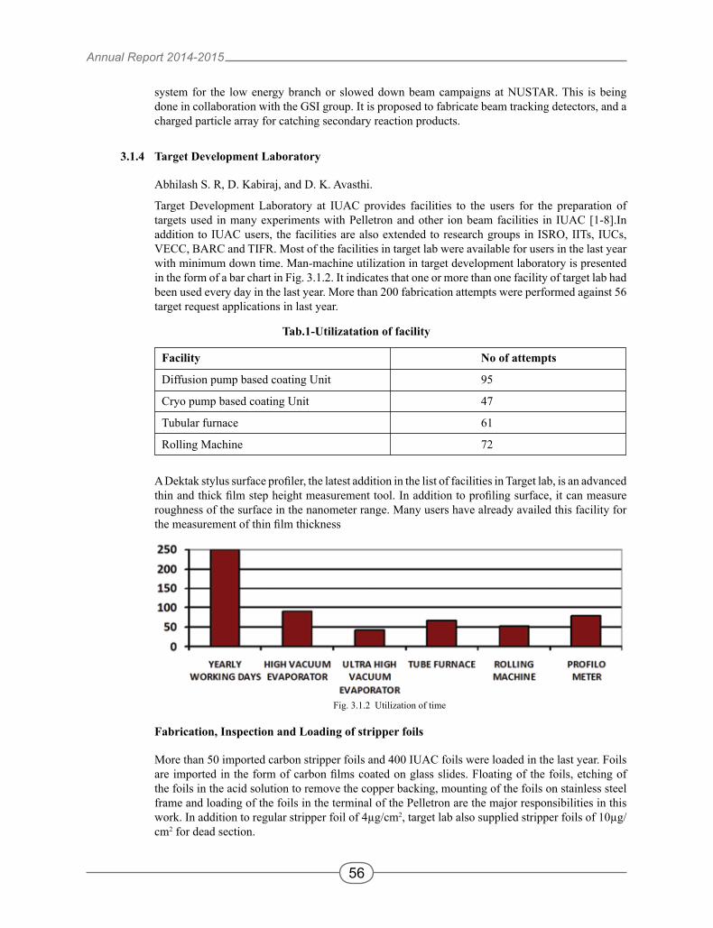
Target Development Laboratory at IUAC provides facilities to the users for the preparation of targets used in many experiments with Pelletron and other ion beam facilities in IUAC [1-8].In addition to IUAC users, the facilities are also extended to research groups in ISRO, IITs, IUCs, VECC, BARC and TIFR. Most of the facilities in target lab were available for users in the last year with minimum down time. Man-machine utilization in target development laboratory is presented in the form of a bar chart in Fig. 3.1.2. It indicates that one or more than one facility of target lab had been used every day in the last year. More than 200 fabrication attempts were performed against 56 target request applications in last year.
A Dektak stylus surface profiler, the latest addition in the list of facilities in Target lab, is an advanced thin and thick film step height measurement tool. In addition to profiling surface, it can measure roughness of the surface in the nanometer range. Many users have already availed this facility for the measurement of thin film thickness
Fabrication, Inspection and Loading of stripper foils
More than 50 imported carbon stripper foils and 400 IUAC foils were loaded in the last year. Foils are imported in the form of carbon films coated on glass slides. Floating of the foils, etching of the foils in the acid solution to remove the copper backing, mounting of the foils on stainless steel frame and loading of the foils in the terminal of the Pelletron are the major responsibilities in this work. In addition to regular stripper foil of 4µg/cm2, target lab also supplied stripper foils of 10µg/cm2 for dead section.
Fig. 3.1.2 Utilization of time
Tab.1-Utilizatation of facility
Facility No of attempts
Diffusion pump based coating Unit 95
Cryo pump based coating Unit 47
Tubular furnace 61
Rolling Machine 72
Annual Report 2014-2015
57
Tab.2- List of recently fabricated targets
Sl.No Description of Method Sl.No Description of Method Target Target
9. 194Pt,100μg/cm2 E-Gun 23. 160Gd,500μg/cm2 Rolling
10. 196Pt,200μg/cm2 E-Gun 24. 154Sm,1200μg/cm2 Rolling
11. 184W,200μg/cm2 E-Gun 25. 116Cd,1100μg/cm2 Rolling
12. 148Nd,250μg/cm2 E-Gun 26. 94Mo,1000μg/cm2 Rolling
13. 150Nd,250μg/cm2 Thermal heating 27. 124Sn,4000μg/cm2 Rolling
14. 154Sm,150μg/cm2 Thermal heating
Fabrication of targets for nuclear physics experiment
One of the major activities of this laboratory is to prepare targets for nuclear physics experiment.Target lab had successfully fabricated and delivered many isotopically enriched nucleartargets.Approximately Rs 20 lakhs were spent for the procurement of isotopes in the last year. List of few recently fabricated nuclear targets is shown in Tab.2
1) Target development of rare earth elements
Most of the rare earth elements are not stable in the atmosphere. High oxidizing tendency of these metals is the major challenge during fabrication and preservation of targets.Target lab is successful in delivering many targets of rare earth metals like Sc, Ce, Pr, Nd, Pm, Sm, Gd, Tb, Dy, Ho, Er, Tm, Yb, Lu. Many of them are in isotopically enriched forms.
2) Target development of high melting point material
Due to high melting point, evaporations of materials like W, Ta, Mo are always a difficult task. Power limitation of electron gun, more source-to substrate distance to minimize degradation of substrate, more material wastage etc. are the major issues in the fabrication metals having high melting point. In last year, target lab has successfully fabricated thin targets of Ta, W, Mo. The W targets were fabricated with highest efficiency. More than 20 targets were prepared in a single evaporation.
Annual Report 2014-2015
58
3.1.5 RF & Electronics Laboratory
A. Sarkar, S. Venkataramanan, B.K. Sahu, K. Singh, A. Gupta, M. Jain, P. Singh, D.K. Munda & B.P. Ajithkumar
3.1.5.1 Indian National Gamma Array Electronics
A patent has been granted with patent number: 257820 by Patent office, Government of India for INGA clover electronics module which was registered under the name “Electronic module for gamma ray spectroscopy system”.
3.1.5.2 Front end and PSD electronics for NAND array at IUAC
The analog front electronics for the phase-II of NAND array has been successfully commissioned during this period. The front end electronics, namely PMT voltage divider network, Charge sensitive preamplifier, (50 numbers) have been successfully integrated, tested and commissioned in the array. At present, complete 100 neutron array detectors and corresponding front end electronics are in its place. Based on NAND (Phase-I) facility tests conducted earlier, the various time constants such as TAC range, PSD. TOF (time of flight) DELAY values have been adjusted. The inadequacy of forced air cooling was experienced during continuous test of complete electronic setup, and suitable modifications have been carried out to overcome this problem.
Meanwhile, the master trigger logic, multiplicity circuit for the complete array are being developed to conserve space.
3.1.5.3Developmentofsolidstate'L'bandamplifier
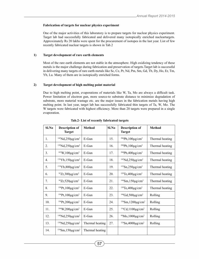
A solid state 'L' band power amplifier capable of delivering up to 50 watts using RF power modules has been prototyped and characterized in order to develop various skills such as microwave layout technique, RF power splitter and combiner technique, characterization with microwave capable equipments such as network analyzer, spectrum analyzer and RF power meter. Wilkinson power divider, 100watt power attenuator are homemade which were thoroughly characterized with above test equipments.
Fig. 3.1.3 Block diagram of L Band Power Amplifier test set up
Annual Report 2014-2015
59
3.1.5.4 Accelerator control systems at IUAC
The Inter University Accelerator Centre (IUAC) has a 16MV tandem accelerator (Pelletron), a super-conducting heavy ion linear accelerator (LINAC), low energy ion beam facility (LEIBF) and many other facilities, which are running round the clock and are controlled through PC based distributed control system. It is absolutely necessary to have a highly reliable digital/analog control modules which will run over the years with minimum power consumption. The embedded computers are interfaced to the devices of the accelerator using VME, CAMAC, IMACS (Indigenous Measurement and Control System) crates, and each of these crates run a server program. The client computers use the X-window graphics and custom made shaft encoder knobs hardware interfaced to them to provide the operator interface. To reduce the module numbers and hence the power consumption, we have adopted high density VME standard for HCI (High Current Injector).
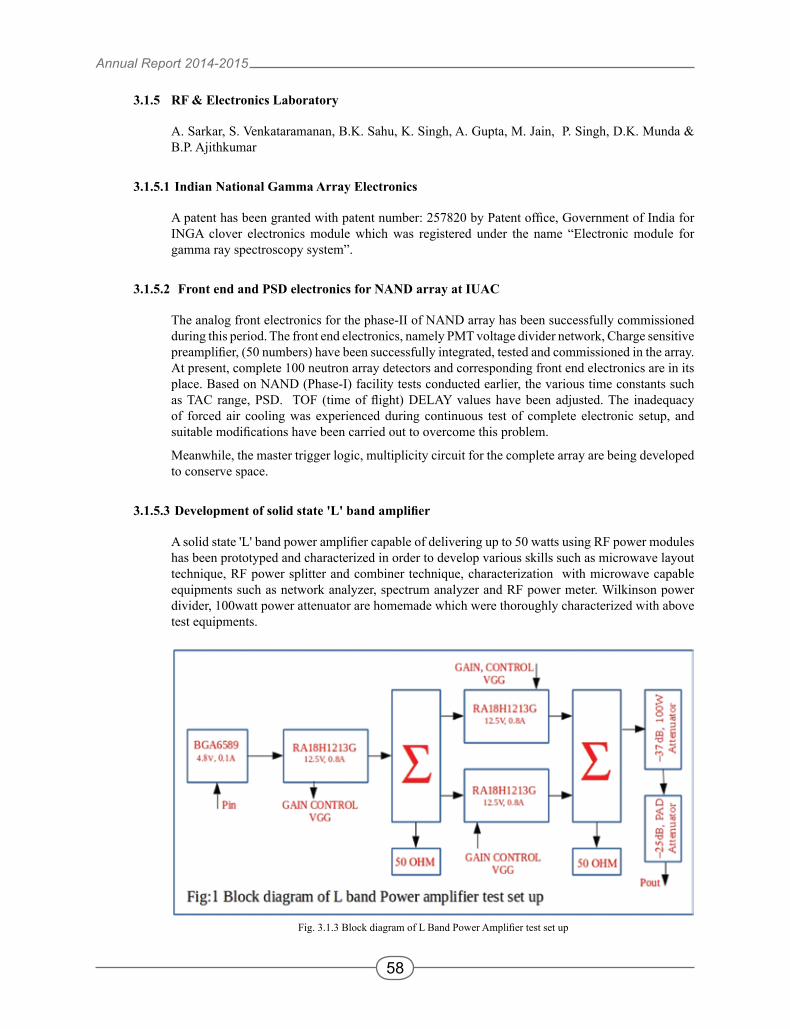
3.1.5.5 VME bus interface to magnet power supply
Fig. 3.1.4 (a) Schematic for USART interface (b) Custom hardware card for magnet power supply
For CAMAC and IMACS servers the magnet power supplies are controlled and monitored using customized hardware i.e. IGOR (Input Gate Output Register), single width module in respective form factors. For HCI control system these magnet power supplies will be used in large numbers. Since we are adopting VME bus based control servers for HCI thus we have to look for remote control option for these power supplies in VME form factor. There are quad channel serial I/O boards commercially available in VME form factor. We have indigenously developed serial interface card for our in-house developed magnet power supplies. Now these power supplies are serially controllable via VME modules in our accelerator control system. The serial peripheral interface (RS232) for our in-house developed magnet power supplies has been implemented using a micro-controller. The micro-controller is working as a bridge with one end USART and other end parallel bus. The board takes data serially from VME control module and parallel data is written into the power supply control logic. The firmware has been written in C-language. The interface card schematic and hardware for the power supply is shown in Fig. 3.1.4.
Annual Report 2014-2015
60
3.1.6 COMPUTER AND COMMUNICATIONS
S.Mookerjee, E.T Subramaniam, S.Bhatnagar, I. Satpathy
The major activities this year include the operation of the High Performance Computing facility at the Centre, a major reorganization of of the Centre's local area network, major enhancements to the Centre's enterprise computing and administration database package, and significant progress in the development of a DSP-based universal data acquisition system.
3.1.6.1 High Performance Computing Facility
The Centre's high performance computing facility, sanctioned by the Department of Science and Technology, is targeted at computational chemists, physicists and biologists in the university system, working in the areas of materials science, atomic and molecular physics and chemistry, radiation biology and nuclear physics. The facility consists of three major systems: a 3200-core 61 teraflop MPI cluster, an older 768-core 9 teraflop cluster, and a 80-core 400 gigaflop server with 256 GB of shared memory. The facility also has 60 terabytes of storage on two parallel file serving clusters.
The facility completed five years of operation this year, and saw some changes necessitated by the growing number of users, changing usage patterns, and the aging of the older systems. The Airawat shared memory system had been seeing reduced usage because of user preference for the faster MPI clusters, and the greater availability of MPI programs. In addition, the proprietary hardware and software had become expensive to maintain in relation to performance. This year the system was moved to lower priority, and users have been progressively moved out of the system. Similarly, the old cluster Kalki, while still operational on full load, is scheduled to go out of maintenance in the next couple of users. About 50 of the more than 300 Kalki users were given accounts on the new 3200-core cluster k2, and helped to port their applications and data. Over the next year, it is expected that all Kalki users will be shifted to k2.
The year also saw a spurt in the number of users of the facility, and in the number of publications. The increase in the number of users was mainly because of the opening up of the k2 cluster for user access; for some time, new user accounts had not been created because of the overloading of the Kalki cluster. The facility now has more than an estimated 300 users from 120 research groups across the country. The number of publications using the cluster has also touched 40, with a large proportion in well regarded journals. Besides materials science and computational chemistry programs, large scale nuclear physics Monte Cerlo runs were also undertaken by users this year.
A major external security breach and persistent problems with the cooling system, however, led to the downtime of the system going below satisfactory levels for the first time. The hacking attempts, which first started around the middle of 2014 and increased in intensity till the end of that year, finally necessitated a shutdown and complete re-installation of both cluster systems. After the fresh installation, the access network was changed for greater security, all user passwords changed, and a new gateway server was installed. Persistent problems with the water chillers also caused unscheduled shutdowns on a few occasions. The problems were identified as being mainly caused by input voltage issues, and efforts are now being made to rectify this. As a result, the clusters were run on a reduced load for part of the year.
Annual Report 2014-2015
61
3.1.6.2 IUAC LAN and servers
A major overhaul and reorganization of the Centre's local area network was completed this year. The reorganization was necessitated by the move of the central computing facility to the state-of-the-art HPC data centre in the LEIB building. As a result, all central servers, and the core switching system, were shifted from the main building to the new data centre. The edge switches for the ground floor of the main building were also shifted from the old server room, which had over the years become cramped and heated because of the expansion of the servers and core switches. More than a kilometre of fibre had to be laid to move the central switches. As a result of the reorganization, the fibre aggregation in the materials science wing of the LEIB building was done away with. All edge switches across six buildings are now directly connected by fibre to the core switches in the HPC data centre, leading to easier fault diagnosis and fewer points of failure. Six of the edge switches had also to be rewired as a result. The whole exercise was completed with only half a day of network downtime. With the offices of computer group staff also shifting close to the HPC data centre, constant monitoring of the network and servers has now become easier.
The architecture of the WAN access for the local network was also changed, with the IUAC network completely isolated from the HPC facility network. This was done to ensure increased security for both the HPC and IUAC networks against external hacking attempts. Since the HPC facility sees mainly external user access, while the IUAC LAN sees mainly access from inside the local network to external sites, different targeted firewall policies are required for the two networks; this can now be implemented more easily. A Cisco 3750 WAN access router was reintroduced for external ISP access, and a new central switch for the HPC network was added. Firewalls on the web, proxy, mail and ssh access servers were reconfigured.
As part of the regular server refresh cycle, the proxy, web and HPC access servers were migrated to new Fujitsu servers running Scientific Linux 6.5. The mail and LTS servers are proposed to be migrated next year.
3.1.6.3 Administration database package
E. T. Subramaniam
The administration package is evolving continuously for accrual based accounting process. Additional packages for banking reconciliation, assets write off, online registers for consumables, ledger, cash, liability and stationery have been incorporated. The banking and liability modules are being modified as per our administration and auditor's requirements. A miscellaneous services module is being developed. On completion, online trial balance will be possible.
3.1.6.4 NIAS development
E.T. Subramaniam, Kusum Rani
Mass production of digital beam profile monitor (BPM) is undertaken. In situ testing of the same is done at LEIBF of IUAC.
DAQ control system with graphical user interface for MESYTEC remote controller has been developed. The gain, offset etc of the electronic modules can be configured through this interface. This is being used in IUAC's neutron facility.
Annual Report 2014-2015
62
Gamma detector array has been upgraded with bit pattern capability. A novel technique of time stamping the events which is published in RSI 83, 123508 (2012) has been incorporated in the Global Event-identifier Module (GEM), facilitating multiple strobe data acquisition systems like HYRA with INGA.
The NIAS digital signal processing board capable of inferring energy (E), multiple charge (Q1, Q2), time stamping (T) with time of incidence (t), rise time (Rt) with ballistic deficit technique, directly from the output of a pre-amplifier has been designed and the printed circuit board is made. Mass production will be done with help of external agencies after completion of beta testing.
3.1.7 HEALTH PHYSICS LABORATORY
S.P.Lochab, Birendra Singh & Debashish Sen
Health physics group is involved in the field of radiation safety, research and development. Many university faculties and research scholars are using the facilities developed and maintained (gamma chamber, TLD reader, electrochemical work station etc.) by this group. A few of the research scholars have completed their Ph.D. using the facilities and a few research scholars are continuing to do so. Routine maintenance of door interlock and radiation monitors is done. Two low energy X-ray & gamma area monitors have been installed in beam Hall III (near ion source cage). The “Beam on” display board in the Bio Line has been shifted to the control room entrance as per the request of concerned group.
Gamma chamber is open for different users from universities and Institutions. The chamber is in the process of getting relocated to a different place within the office premises. Required AERB approval has been received. Permission for the new AMS facility has been sought. Regular status reports for the Pelletron and RBS facility is being sent to AERB. All dose records are maintained and are also available online.
Extra shielding for the LINAC cryostats has been provided to reduce the existing radiation level beyond the permissible limit. Now the adjoining area is safe for access from radiation safety point of view. The Health Physics lab provide consultancy on radiation protection and radiation shielding calculations for universities which are in the process of installing particle accelerator facilities.
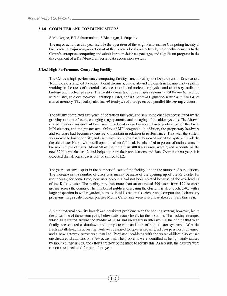
3.1.7.1 Beam Dump and associated shielding calculations for the upcoming FEL Facility
Debashish Sen
A proposal for setting up a 50 MeV Free Electron Laser Facility has been put forward at the Inter University Accelerator Centre. Shielding design of this FEL facility is being planned with reference to the tentative layout given below. For the shielding design we will be using the Monte Carlo particle interaction and transport code FLUKA.
Annual Report 2014-2015
63
Dose rates outside the boundary due to beam loss at the beam dumps during normal operation as well as due to any accidental beam loss at any point on the path of the beam need to be estimated. Dose rates at different experimental and infrastructural facilities due to accidental beam loss at any point, beam tuning failure, etc. also need to be calculated. The thickness of the boundary concrete wall should be decided so as to keep the dose rate below the regulatory limit of 1 µSv/h on its outer side.
The beam dumps are primarily considered to be of composite structure with a graphite core and an iron wall. In the first part of the work, the dose rates will be estimated at the points outside the concrete wall near the beam dumps and other nearby areas. The beam dump geometry is constructed in FLUKA as follows: The electron beam is assumed to move along z-axis. A rectangular parallelopipped represents the graphite core. The iron wall on three sides of this core has been constructed with the help of two infinite coaxial cylinders having axis along the z axis and three perpendicular planes cutting the z axis to define the depth of the graphite core and the thickness of the iron wall. The concrete wall is represented by a second rectangular parallelopipped. Dose rates at different points will be calculated with FLUKA. Accordingly the shielding parameters/dimensions will be chosen. The preliminary calculations are going on.
3.1.7.2 High sensitive phosphor for carbon ion dosimetry
Bhushan P. Korea, N. S. Dhobleb, S. P. Lochab c, S. J. Dhoblea
a Department of Physics, RTM Nagpur University, Nagpur 440033, India.
b Department of Chemistry, Sevadal Mahila Mahavidyalaya, Nagpur 440009, India
c Inter University Accelerator Centre, Aruna Asaf Ali Marg, New Delhi 110067, India
Fig. 3.1.5 The preliminary planned layout of the FEL facility
Annual Report 2014-2015
64
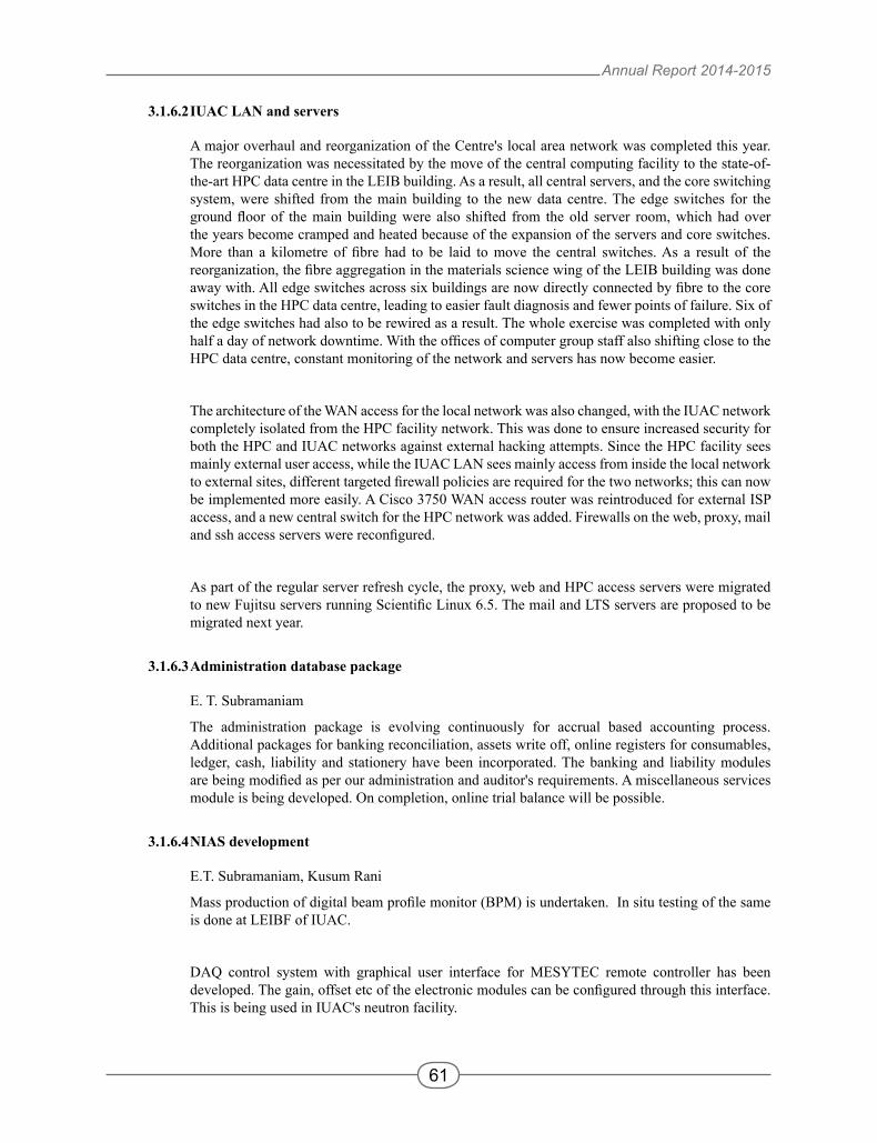
The demand for the dosimetry of charged particle beams has taken a decisive lead because of its utility in cancer diagnosis and therapy1,2. Dy3+ doped CaMg(SO4)
4 (CMS) phosphor was prepared by the acid distillation method and examined in detail with a thermoluminescence study whereby the phosphor was irradiated with γ rays and carbon ion beam. 5mg of CMS phosphor was exposed to γ rays from 60Co and 137Cs sources for various doses. The samples in the form of pellets were irradiated at room temperature by a C5+ ion beam at energies of 50MeV and 75Mev for different ion fluences in the range of 15× 1010 to 30×1012 ions per cm2, using a 16MV tandem van de Graaff type electrostatic accelerator (15 UD pelletron) at the Inter University Accelerator Centre, New Delhi, India. For irradiation, the sample pellets were mounted on a copper target ladder. The copper ladder prevents heating of the sample during swift heavy ion irradiation. For irradiation, the ladder was kept inside the evacuated irradiation chamber. The ion beams were magnetically scanned on a 10mm × 10mm area of sample surface for uniform irradiation. The beam spot size used was 2.5mm2. The pressure of the vacuum chamber during ion beam irradiation was 5 × 10⁻⁴ mbar. A good dosimetric glow curve was observed that is stable against both type of radiation. The TL glow curve of CMS phosphor irradiated with 60Co, 137Cs and C5+ ion beam is shown in Fig. 3.1.6. TL glow curve of CaSO4:Dy3+ is also included for comparison purposes.
Fig. 3.1.6 TL glow curves of the CMS phosphor irradiated with (a) γ-rays from a 60Co source at a 15 Gy dose, (b) γ-rays from a 137Cs source at a 2300mRad dose, (c) C5+ ion beam at 75 MeV with a 216 kGy dose, and (d) comparison between TL glow curves of the CMS phosphor irradiated with a C5+ ion beam at 50 and 75 MeV energies, and γ-rays from a 60Co
source at a 15 Gy dose and a 137Cs source at a 2300 mRad dose.
The CMS doped with 0.2mol% of Dy3+ showed 3.5 times more sensitive than commercially available CaSO4:Dy3+ phosphor when irradiated with a carbon ion beam. The observed glow curve variation in the values of trapping parameters with a change in ion beam energy suggest more complex interactions of ion beam within the phosphor at higher energies.
Annual Report 2014-2015
65
REFERENCES: [1]. W. Barth, L. Dahl J. Glatz, P. Forck and J. Klabunde, Proceeding of the Particle Accelerator Conference, Chicago, 2001, Vol.
3281. [2]. T. Haberer, AIP Conf. Proc., 2002, vol. 161.
3.1.7.3 Luminescence characteristics of C5+ ions and 60Co irradiated Li2BaP2O7:Dy3+
J. A. Wania, N. S. Dhobleb, S. P. Lochabc, S. J. Dhoblea
a Department of Physics, RTM Nagpur University, Nagpur 440033, India.
b Department of Chemistry, Sevadal Mahila Mahavidyalaya, Nagpur 4400o9, India
c Inter University Accelerator Centre, Aruna Asaf Ali Marg, New Delhi 110067, India
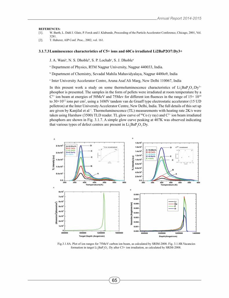
In this present work a study on some thermoluminescence characteristics of Li2BaP2O7:Dy3+ phosphor is presented. The samples in the form of pellets were irradiated at room temperature by a C5+ ion beam at energies of 50MeV and 75Mev for different ion fluences in the range of 15× 1010 to 30×1012 ions per cm2, using a 16MV tandem van de Graaff type electrostatic accelerator (15 UD pelletron) at the Inter University Accelerator Centre, New Delhi, India. The full details of this set up are given by Kanjilal et al 1. Thermoluminescence (TL) measurements with heating rate 2K/s were taken using Harshaw (3500) TLD reader. TL glow curve of 60Co (γ ray) and C5+ ion beam irradiated phosphors are shown in Fig. 3.1.7. A simple glow curve peaking at 407K was observed indicating that various types of defect centres are present in Li2BaP2O7:Dy.
Fig.3.1.8A. Plot of ion ranges for 75MeV carbon ion beam, as calculated by SRIM-2008. Fig. 3.1.8B.Vacancies formation in target Li2BaP2O7: Dy after C5+ ion irradiation, as calculated by SRIM-2008.
Annual Report 2014-2015
66
TL showed variation with enhancement in amount of dose imparted to Li2BaP2O7:Dy phosphor. To study the effect of different doses on Li2BaP2O7:Dy phosphor, dose exposure was varied and it was observed that highest TL intensity occured at around1kGy irradiation followed by drop in TL intensity on further enhancement in doses. Also SRIM based calculations were performed to study the effect of C5+ ion beams on the samples of Li2BaP2O7:Dy. SRIM calculation shows that Ba2+ vacancies are highest in number. The range of 75MeV carbon ion beam inside the phosphor was calculated using SRIM and is shown in Fig. 3.1.8A. From calculations it was observed that 75MeV carbon ion beam penetrates deeply, but linear energy transfer (LET) value is just 1.24 (MeV)/(mg/cm2) for 75MeV carbon ion beam. The vacancy distribution profile of carbon ion irradiated phosphor at 75MeV energy of carbon beam is shown in Fig. 3.1.8B. The depth for maximum vacancies formation is 126 µm at 75Mev energy of C5+ ion beam.
REFERENCES: [1] D. Kanjilal, S. Chopra, M. M. Narayanan, I .S. Iyer, J .J. R .Vandana, S.K. Datta, Nucl.Instrum. Methods A 328 (1993) 97-
100.
3.1.7.4 TL investigation of CaSO4: Dy
Shaila Bahl a, S.P. Lochabb, Birendra Singhb, Pratik Kumar a
a Medical Physics Unit, IRCH, AIIMS, New Delhi 110029, India
b Inter-University Accelerator Center, Aruna Asaf Ali Marg, New Delhi 110067, India
Thermoluminescent phosphors such as Lithium Floride (LiF) and Calcium sulfate (CaSO4) based phosphors are known to be the workhorse of TL dosimetry especially in the areas of medical dosimetry, personnel monitoring etc. This work deals with the preparation and study of CaSO4:Dy,Mn in its microcrystalline form. The sample was prepared by the method adopted by Yamashita et al. (1971). Some modification in the preparation has been performed which are given below along with detailed TL study.
The present preparation procedure of CaSO4 involves the standard production route known which is based on the recrystallization method as proposed by Yamashita et al (1971). However the difference between the method adopted by Yamashita et al and our preparation lies in the form of activator compounds i.e. chloride salt of Dysprosium (in the form of DyCl3) was used unlike Dy2O3 as used by Yamashita. Moreover Manganese (in the form of MnCl2) was also added as a co-dopant to produce CaSO4:Dy,Mn for its sensitivity. All the samples were prepared by dissolving AR grade CaSO4 matrix and the dopants in desired ratios and quantities in hot concentrated sulphuric acid, followed by slow evaporation of the solvent using a temperature controlled electric heater at 623 K in a well closed system to avoid acid vapours escape to the atmosphere. The acid vapours were dragged by an air flux by means of a suction pump, and collected in the flask attached. The powder thus obtained was the required microcrystalline phosphor. The sample was washed several times with water to remove any traces of acid.
3.1.7.5 Study of thermoluminescence glow curves & XRD patterns of nanocrystalline samples
S.P. Lochab a, Kanika Sharmab, Chirag Malik b, Anitab, Birendra Singhb & Anant Pandey b
a Inter-University Accelerator Center, Aruna Asaf Ali Marg, New Delhi 110067, India
b Department of Physics, University of Delhi, New Delhi 110021, India
Annual Report 2014-2015
67
We have prepared a number of nanocrystalline samples of BaSO4:Eu by the chemical co-precipitation method, irradiated them with a range of doses of gamma radiation in the gamma chamber 1200 at IUAC and studied their thermoluminescence characteristics using Harshaw 3500 TLD reader. We have also done the X-Ray Diffraction study of the samples at the XRD facility at IUAC. Another material that has been prepared and studied for dosimetry purpose using the solid state diffusion technique is K2Ca2(SO4)3 doped with various combinations of impurities such as Eu, Mg, and Cu. These works have been selected for presentation in a couple of international conferences which we intend to attend in the coming days. The students have been using the facilities of the Health Physics Lab mainly for the preparation of samples, their irradiation with gamma radiation, taking readouts of thermoluminescence glow-curves and XRD patterns etc.
3.1.8 Data Support Laboratory
V.V.V.Satyanarayana, Ruby Santhi and P.Sugathan
Data Support Laboratory provides support to users on data acquisition & nuclear electronics setup during experiments. In the data room, two on-line data acquisition based on CAMAC systems are maintained for data collection during in beam experiments and two desktop workstations for off-line analysis. The lab maintains the data acquisition computers & private LAN for data network. The lab also provides support to the local data acquisition systems that uses indigenously made List Processor Crate controllers and Candle data acquisition software. Apart from providing regular user support and maintenance of the setup, a few electronic modules have been developed and some existing modules serviced. The lab also procures required electronic modules, co-axial connectors and cables required for user support.
3.1.8.1 Data Acquisition Systems upgrade in Data Room
Rajesh Nirdoshi, Ruby Santi, Kundan Singh and P . Sugathan
Last year we have upgraded the on-line data acquisition system to USB based commercial controller CMC100 and few experiments have been performed using the system. The modified version of “Freedom” data acquisition software used the device driver and readout libraries supporting cmc100 under Linux 2.6 kernel. We have tested the driver and readout on 64-bit operating system using Scietific Linux 6.5(64 bit). The code for the readout part has been modified accordingly and data collected under 64-bit version. For VME data acquisition, we have implemented the readout of Mesytec 13 bit ADC in Freedom software and data was collected from a gamma detector using 152Eu radioactive source.
3.1.8.2 Development of Electronic Modules
V.V.V.Satyanarayana
A few electronics modules, such as Current Integrators, Quad Logic Fan In / Fan Out and LEMO to flat ribbon header adapters have been developed and installed in various experimental facilities at IUAC.
AccuracyAmpere meter < 1% of full scaleCoulomb meter < 1% of reading
Input Impedance 1nA to 300nA < 1.5kΩ to 500Ω1µA to 30mA < 500Ω
Overload Over-voltage protection on protection the input and over current
indication on front panel
Counter Counter click, 10 clicks/sec at full scale
Polarity Automatic adjustment to current polarity with LED indication o front-panel
Output signals Analog voltage Pulse output 0 to ±1Vfs @
10mA 0 to 10Hz fs, TTL
Mechanical 19 Inch rack mount dimensions (310mm x 135mm)
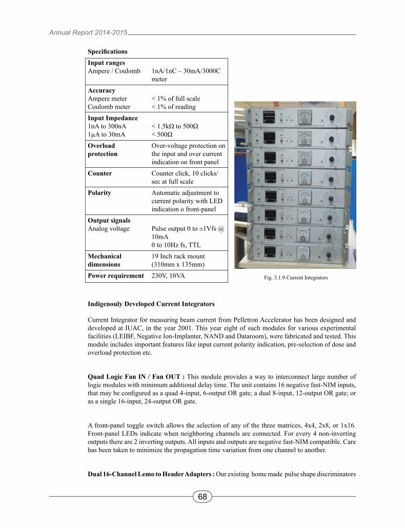
Power requirement 230V, 10VA Fig. 3.1.9 Current Integrators
Indigenouly Developed Current Integrators
Current Integrator for measuring beam current from Pelletron Accelerator has been designed and developed at IUAC, in the year 2001. This year eight of such modules for various experimental facilities (LEIBF, Negative Ion-Implanter, NAND and Dataroom), were fabricated and tested. This module includes important features like input current polarity indication, pre-selection of dose and overload protection etc.
Quad Logic Fan IN / Fan OUT : This module provides a way to interconnect large number of logic modules with minimum additional delay time. The unit contains 16 negative fast-NIM inputs, that may be configured as a quad 4-input, 6-output OR gate; a dual 8-input, 12-output OR gate; or as a single 16-input, 24-output OR gate.
A front-panel toggle switch allows the selection of any of the three matrices, 4x4, 2x8, or 1x16. Front-panel LEDs indicate when neighboring channels are connected. For every 4 non-inverting outputs there are 2 inverting outputs. All inputs and outputs are negative fast-NIM compatible. Care has been taken to minimize the propagation time variation from one channel to another.
Dual 16-Channel Lemo to Header Adapters : Our existing home made pulse shape discriminators
Annual Report 2014-2015
69
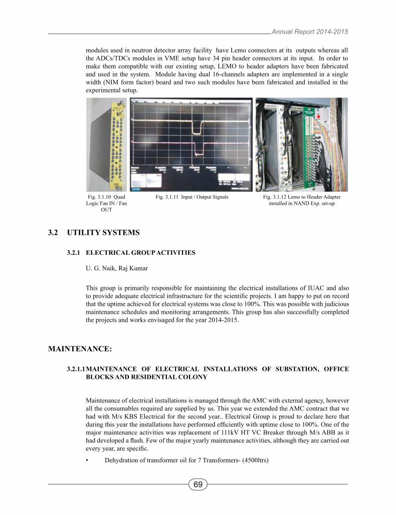
modules used in neutron detector array facility have Lemo connectors at its outputs whereas all the ADCs/TDCs modules in VME setup have 34 pin header connectors at its input. In order to make them compatible with our existing setup, LEMO to header adapters have been fabricated and used in the system. Module having dual 16-channels adapters are implemented in a single width (NIM form factor) board and two such modules have been fabricated and installed in the experimental setup.
Fig. 3.1.10 Quad Logic Fan IN / Fan
OUT
Fig. 3.1.11 Input / Output Signals Fig. 3.1.12 Lemo to Header Adapter installed in NAND Exp. set-up
3.2 UTILITY SYSTEMS
3.2.1 ELECTRICAL GROUP ACTIVITIES
U. G. Naik, Raj Kumar
This group is primarily responsible for maintaining the electrical installations of IUAC and also to provide adequate electrical infrastructure for the scientific projects. I am happy to put on record that the uptime achieved for electrical systems was close to 100%. This was possible with judicious maintenance schedules and monitoring arrangements. This group has also successfully completed the projects and works envisaged for the year 2014-2015.
MAINTENANCE:
3.2.1.1 MAINTENANCE OF ELECTRICAL INSTALLATIONS OF SUBSTATION, OFFICE BLOCKS AND RESIDENTIAL COLONY
Maintenance of electrical installations is managed through the AMC with external agency, however all the consumables required are supplied by us. This year we extended the AMC contract that we had with M/s KBS Electrical for the second year.. Electrical Group is proud to declare here that during this year the installations have performed efficiently with uptime close to 100%. One of the major maintenance activities was replacement of 111kV HT VC Breaker through M/s ABB as it had developed a flash. Few of the major yearly maintenance activities, although they are carried out every year, are specific.
• Dehydration of transformer oil for 7 Transformers- (4500ltrs)
Annual Report 2014-2015
70
• Periodic maintenance of LT panels, Distribution boards and other accessories, Lighting, Fixtures, lighting and power circuits.
• Servicing of DG sets 60kVAX2nos,1*750KVA, 2X 320 kVA, 1X 100 kVA-twice a year. • Maintenance of street lighting and earthing. • LT Bush replacement for 1000KVA Transformer#5
3.2.1.2 CAPTIVE POWER INSTALLATIONS
Institute had a captive power base of 1560 KVA, having DG capacities from 100-750KVA. In the financial year 2013-14 the group has successfully managed to upgrade it to 2500KVA. The scheme worked out has a capability to synchronise 3*750KVA DG sets making a total capacity of 2250 KVA that provides total redundancy to the critical loads. The group has shown ever readiness in running the systems round the clock O&M activities within short period if need arises.
Leakages were fixed by rewelding bend in fuel lines of 750 kVA DG sets in line.
3.2.1.3 VOLTAGE STABILISERS
Voltage stabilisers supporting the insatllations having capacities from 30KVA to 1000kVA are working in healthy conditions with practice of periodic maintenance and have kept 100% up time. No failure occurred during the financial year.
3.2.1.4 UPS INSTALLATIONS
The institute has 5sets of 2*60KVA UPS, 3*300KVA, 4*200KVA, 1*50KVA and around 20 nos. of 2-10KVA UPS systems maintained by electrical group. These are under supervision and control of this group. Although the day to day operations is carried out by electrical group the comprehensive AMC order have been placed on the manufacturer for all the sets out of warrantee period. Batteries worth 3 lakhs were replaced for UPS during the FY 2014-15..
3.2.1.5 POWER FACTOR COMPENSATION
Electrical group is very happy to declare that yet again we achieved average power factor of 0.98 lag throughout the year. Our system power factor without correction is about 0.85 and by raising it we saved around Rs.110 lakhs through the year from energy billing.
3.2.1.6 COMMUNICATION EQUIPMENTS
Electrical group maintains the 14 hand held radio stations (Walkie-talkie) and one base station. The routine maintenance such as replacement of batteries, antennas, switches etc is managed by this group. This year we have given AMC for service to the authorized agency of MOTOROLA @ cost of 25000/- per annum. The group takes the responsibility of getting the revalidation of license periodically from the Ministry of telecommunications.
3.2.1.7 ENERGY SAVING
Energy savings measures taken earlier continued in the areas where we had installed the energy saving time switches and CFL lamps, T-5 lamps etc. This financial year we have added motion sensors in few toilets and committee rooms on experimental basis. On the same measure this year we have tried LED lights in few laboratories developed this FY. We are expecting save 70 % energy in these installations over the conventional T-8 Fl. Tube fittings.
Annual Report 2014-2015
71
PROJECT WORKS:
3.2.1.8 ELECTRICAL EARTHING
Electrical group has successfully installed electrical earthing using chemical earthing for high voltage cage area, electronics and power in the beam hall-III.
3.2.1.9 ELECTRICAL WORKS FOR AMS FACILITY
Power Control panel of AMS lab has been procured and installed with adequate size of copper power cable and connected with UPS power. Adequate sized copper earthing links also have been provided.
3.2.1.10 LIGHTING WORKS FOR EBW MACHINE ROOM
Electrical group had taken up electrical works for this and provided the energy efficient LED lights.
3.2.2 AIR CONDITIONING, WATER SYSTEM AND COOLING EQUIPMENTS
P. Gupta, A. J. Malyadri, Bishamber Kumar
AC SYSTEM IUAC's central air conditioning / low temperature cooling system of Phase-1 consists of 4x100 TR
reciprocating and 2x200 TR screw compressor based Central AC plants. They performed with 100% uptime. Appropriate maintenance ensured that the safety record of the plant was 100% and the power consumption maintained at optimum levels. The 200 TR screw chillers ran around 4000 hours each. Other rotary equipment has logged in about 188,500 continuous run hours. It is relevant to note that the industrial norms specify ~25,000 run-hours for the life of compressors and ~50000 hours for other rotating equipment. A new 250 TR Screw Chiller was successfully installed and commissioned in August 2014. This chiller is catering to EBW, UPS, Beamhall - II and cryogenic activities, etc. The Phase-III, central AC plant with its installed capacity of 250 TR performed to an uptime of 100%.
The highlight of the operation and maintenance of the above systems was the in-house supervision provided to the contracts, thereby affecting significant savings. The hook-up of Ph-II&III plants has facilitated an in-built redundancy and affected substantial power savings. The yearly maintenance costs have been maintained at approximately one-eighth of the national standards and one third of the world class industrial bench marks. Though, the plants have aged, yet the MTBF for all the equipment have far exceeded acceptable norms. The equipment being into their twenty-sixth year of sustained operations have far outlived their economic lives. High standards of maintenance has ensured that the equipment possess high operational reliability.
WATER SYSTEM IUAC's centralized water system of Phase-I feeds low temperature cooling water of a total heat removal
capacity of 115 TR, potable water supply and the gardening water supply, etc. It performed to an operational uptime of 100%. This was possible due to the stringent maintenance practices, which were followed over the years. The system has already overshot 142,000 hours beyond its expected life span. IUAC's centralized water system of Phase-II feeding low temperature cooling water of a total heat removal capacity of 80 TR, liquid helium cooling water of approx. 350 TR heat removal capacity and potable water supply also performed to an uptime of 100%. Further, centralized water system of Phase-III feeding low temperature cooling water of a total heat removal capacity of 80 TR and potable water supply performed to an uptime
Annual Report 2014-2015
72
of 100%. 150 KLD Sewage Treatment Plant (STP) also performed satisfactorily.
A strict monitoring on the water quality ensured that the flow paths are maintained in a healthy state. The maintenance costs were kept significantly low as compared to world class bench mark values.
COOLING SYSTEM Availability of equipment was recorded at 99% plus.
PLANNED WORKS EXECUTED DURING THE YEAR:
• Commissioning of 250 TR Ph-II A/C plant
• Commissioning of Ultra-Pure Analytical Type-I DI Water Plant for super conducting resonator cleaning facility in Beamhall#II.
• Provision of Closed-loop Water Chiller for PKDELIS Cryo-Coolers
• Provision of De-Humidifier for LEIBF High Voltage Deck Area
• Commissioning of Clean Room of Class-100 for LINAC module servicing
• Commissioning of Dust Free Room for RFQ assembly work in Beam Hall#III
IUAC workshop is an ideal workshop equipped with modern machining and welding facilities to support new development programs, pelletron and other accelerator related jobs, various laboratories and large number of user community.
The major facilities of the workshop are Machine shop and Welding shop.
The machine shop is equipped with a five axis Vertical Machining Centre and a CNC lathe. Apart from these, we have four conventional lathes, two milling machines and a Radial drilling machine catering to the tool room jobs. Most of these machines are of HMT make, fitted with DROs for achieving higher accuracy and better productivity. Apart from these, we have cylindrical grinder, tool and cutter grinder, horizontal and vertical band saw machines, etc. for general requirements. We have also added one Wax moulding facility for melting the wax and shaping it into required shape & size. It can handle 100 kgs of wax at a time. Moulded wax ingots were used for making beam dumps. We also have the CAD facility, Solid Works for the design and drafting purpose. We also have VISI CAM for the CAM support for the Vertical Machining Centre and CNC lathe. Two portable CMMs are also available in the metrology section.
Workshop has been involved in development activities of new system as well as a large-scale production of beam line components right from the inception of IUAC. Most of the beam line components used for the new beam lines was fabricated in the IUAC Workshop. Workshop continues to assist the entire in-house fabrication activities of LINAC, RFQ and DTL for HCI, INGA, HYRA, 1.7Mev Pelletron as well as the Cryogenic component developments.
Annual Report 2014-2015
73
Welding shop is having high quality TIG welding machine and equipment. Some of the TIG machines can give pulsed arc for the thin section welding. Air plasma cutter with a capacity to cut up to 40mm thickness of stainless steel is used extensively. Aluminum welding and Oxy-acetylene cutting and brazing set ups are also available. We have a micro plasma machine from Air Liquide, France for very thin section welding.
IUAC workshop is providing Apprentice training for the ITI passed students in both welding shop as well as in machine shop. Basic workshop training is also provided for the scientist trainees and Ph.D. students enrolled in IUAC.
Some of the major completed/ongoing projects where workshop support is crucial:
• Beam Dump for NAND
• Magnetic Quadrupoles for HCI
• Radio Frequency Quadrupole Project
• Drift Tube LINAC Project
• High current proton source for 2.45 GHz source development program
• 48.5 MHz Buncher for HCI project
• LEIBF -II Beam line components
• 25 kW-97MHz RF Amplifier Housing fabrication
• Slow Tuner for LINAC
3.2.4 CIVIL WORKS
M.K.Gupta, Harshwardhan
Works under Civil Section
• Major expansion Projects - right now construction of (i)Auditorium (ii) Addition of one floor in Main Lab. Building
• Minor Projects
• Minor Works (additions, alterations, upgradation, modification in the existing Civil works)
• Civil Maintenance
• External Cleaning of the Campus
• Liasion with various Govt. and external agencies for miscellaneous interactions
• Key management of the Centre
Important Civil Activities during the Year 2014-15
Following important Civil works were undertaken during the year 2014-15 in addition to routine Civil maintenance and minor works:
1. Work for construction of Auditorium & Lab. block Extn. in progress in association with M/S RITES (our Project management consultant). About 75% Civil works complete.
2. Civil development works around HPC chillers on W-side of LEIB building
Annual Report 2014-2015
74
3. Civil development works around DG area near Engg. Building
4. Civil works around STP(Sewage Treatment Plant) area near NE boundary wall
5. Renovation of EBW room (414) in UB-II building
6. Construction of double entry door for R.N. 413 in UB-II building
7. P/F MS Gate and GI chain link fencing around LN2 tanks near BH-III
8. Renovation of Toilets near Dining Hall
9. New Security Guard cabin for Director’s residence
10. Epoxy floor coating in compressor room of Helium building
11. P/F Sensor based flushing valve(3 nos.) in Gents toilet near Lounge area,GF of Main building
12. Epoxy floor coating in Deck area of BH-III
3.2.5 COMPRESSED AIR SYSTEM AND MATERIAL HANDLING EQUIPMENTS
K.K. Soni and Bishamber Kumar (MG I)
Group is associated with the following activities:
i) Compressed Air System: Compressed air plant ( Ph-I & PH-II ) consisting of three nos. screw compressors each of 115M3/Hr capacity, along with air dryers & filters with capacity of 3000 lpm @ 9.00 Kg/cm2 have been maintaining uninterrupted air supply to tower, Beam Hall- I, Beam Hall -II and other associated lab areas round the clock. In order to further increase the reliability of the Compressed air supply at constant pressure, a 25 M3 Storage tank is added in the system. It is installed in the Compressed air line on the roof of UB II. Pneumatic connections have been extended to all the labs.
A stand by screw compressor of 115 M3/Hr capacity is added in PH I plant in order to meet any eventuality of breakdown of existing compressor. A storage tank of 1KL is added between compressor and Air dryer for smooth flow of compressed Air.
Further to ensure low dew point of the air, the compressed air is passed through two refrigerated type air dryers of 4300 LPM capacity. Ultra high filters of boro silicate and carbon filters are provided in different location of the compressed air to provide clean air free from dust and oil particles. The filter cartridges of Ultra high filters are changed once a year to maintain the quality of supply air.
Since Reciprocating compressors which are more power consuming and source of excess oil contamination in the compressed air, therefore, generally we do not operate the reciprocating compressors. Compressed air piping has been extended to Lab I, Lab II and New Workshop building.
ii) Industrial Gases: Various industrial gases required in different labs have been made available from time to time. Special gases like Iso Butane and mixture gases are also procured for labs.
iii) Elevator: The Elevator has been replaced of similar capacity with modern features. The new Elevator is put in to use.
Annual Report 2014-2015
75
iv) Material Handling System : Periodic maintenance / servicing of more than 14 Nos E.O.T cranes and electric hoists of various capacity varying from 1 Tonne to 7.5 Tones are being carried out periodically and the same have been working smoothly. Two more cranes of 7.5 T capacity in BH III and 2 T Electrical Hoist in BH III has been added. All the important area cranes are put on remote control operation for safe handling of machines.
v) Fire Extinguishers: Annual refilling and periodic maintenance of all the fire extinguishers have been carried out. New fire extinguishers have been installed in newly constructed BH III, store area , Lab I and Lab II area, Workshop building. Some more sign boards including the "Escape route" is added in the building which shines even in darkness. .Demonstration for use of Fire extinguishers has been arranged and all the users and IUAC employees are trained to use the fire extinguishers.
New buildings under PH II part II have the newly added Fire safety norms which includes pressurised water hydrant system. It includes centralized pressurised water system connected to underground Water tank and water pumps which maintain continuous water pressure in the water hydrant line. This system is available in PH II Part II buildings. All the Labs and experimental areas have smoke detectors having display unit and sound alarm at Reception of Lab I which is attended round the clock by operator.


![COMPLETE PELLETRON SYSTEMS FOR ION BEAM ......National Electrostatics Corp. 7540 Graber Rd., P.O. Box 620310, Middleton, WI 53562-0310 USA 06/14 [IBA] COMPLETE PELLETRON SYSTEMS FOR](https://static.documents.pub/doc/80x56/5f218a320471711893037fe6/complete-pelletron-systems-for-ion-beam-national-electrostatics-corp-7540.jpg)


