Packet Switching Nature seems … to reach her ends by long circuitous routes. --- Rudolph Lotze Acknowledgement: this lecture is partially based on the slides of Dr. Larry Peterson Problem: not all networks are directly connected Limitations of directly connected networks: limit on the number of hosts supportable limit on the geographic span of the network Hongwei Zhang http://www.cs.wayne.edu/~hzhang
Transcript
Packet Switching
Nature seems … to reach her ends by long circuitous routes.
--- Rudolph Lotze
Acknowledgement: this lecture is partially based on the slides of Dr. Larry Peterson
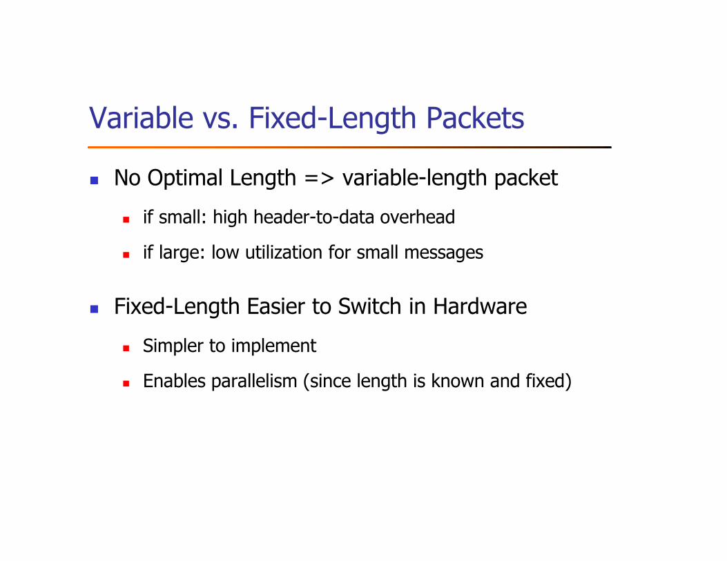
Problem: not all networks are directly connected
Limitations of directly connected networks:
� limit on the number of hosts supportable
� limit on the geographic span of the network
Hongwei Zhang
http://www.cs.wayne.edu/~hzhang
Outline
� Switching and Forwarding
� Bridges and Extended LANs
� Cell Switching
� Implementation
� Discussion
Outline
� Switching and Forwarding
� Bridges and Extended LANs
� Cell Switching
� Implementation
� Discussion
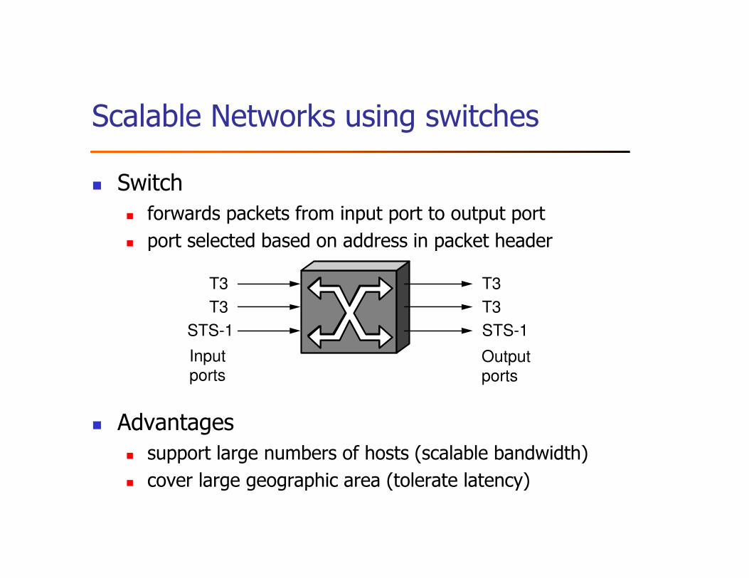
Scalable Networks using switches
� Switch
� forwards packets from input port to output port
� port selected based on address in packet header
� Advantages
� support large numbers of hosts (scalable bandwidth)
� cover large geographic area (tolerate latency)
Inputports
T3
T3
STS-1
T3
T3
STS-1
Switch
Outputports
Problem statement
� Given a multi-hop network where nodes may not be
directly connected, how does a switch decide where
(e.g., which output port) to forward each packet?
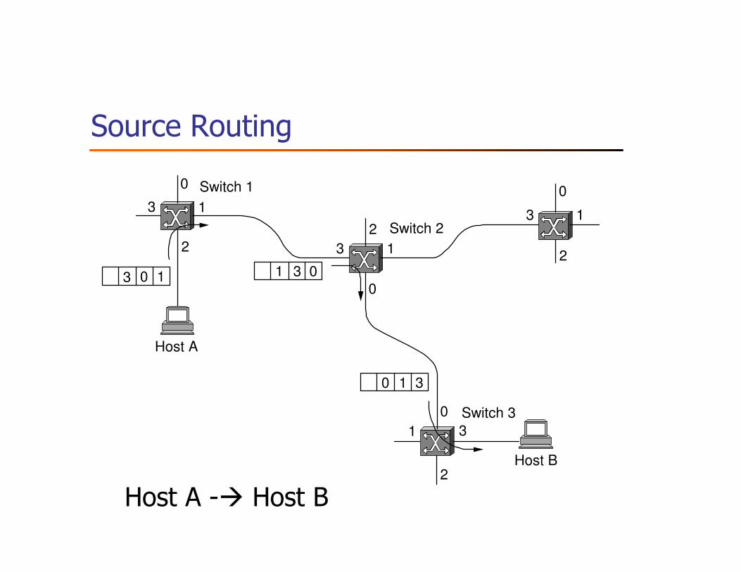
Source Routing
0
13
2
0
1 3
2
0
13
2
0
13
2
3 0 1 3 01
30 1
Switch 3
Host B
Switch 2
Host A
Switch 1
Host A -� Host B
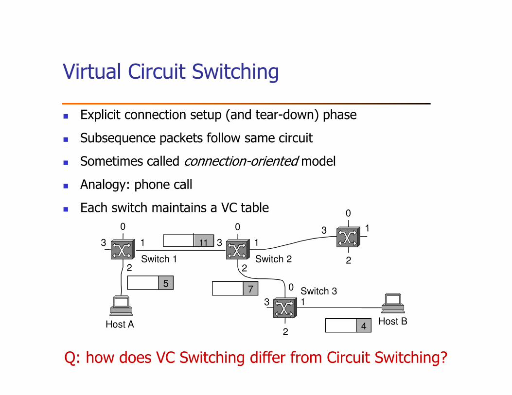
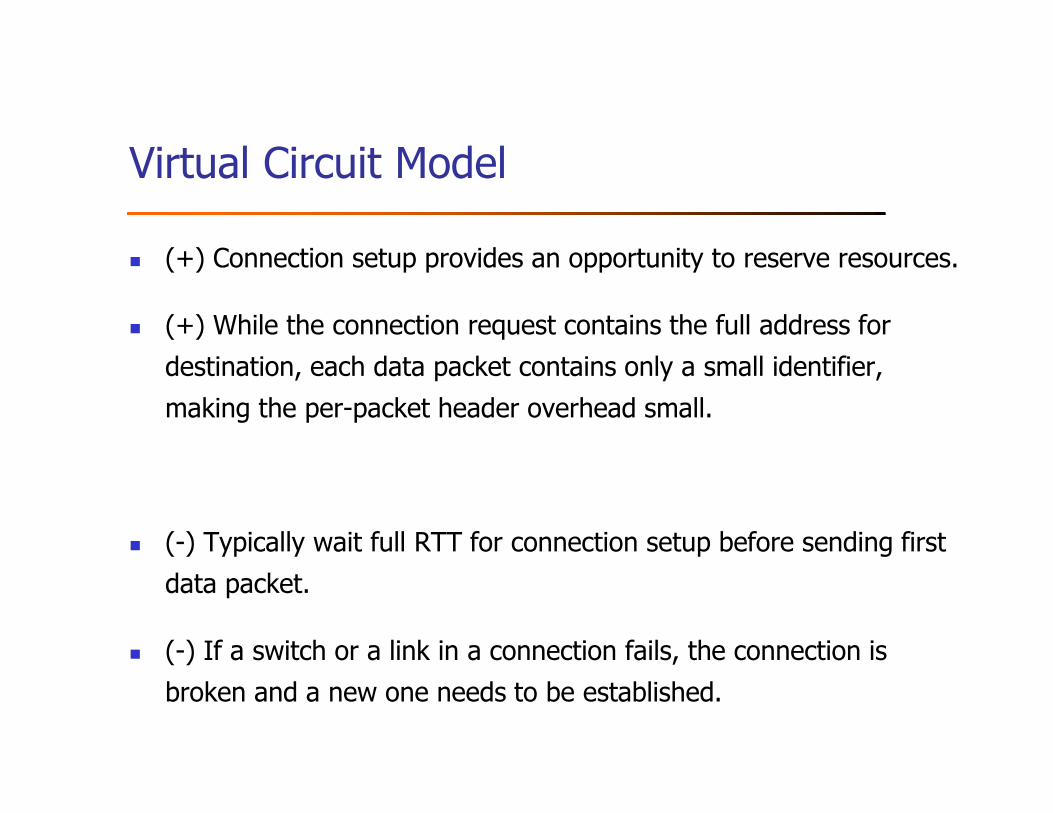
Virtual Circuit Switching
� Explicit connection setup (and tear-down) phase
� Subsequence packets follow same circuit
� Sometimes called connection-oriented model
� Analogy: phone call
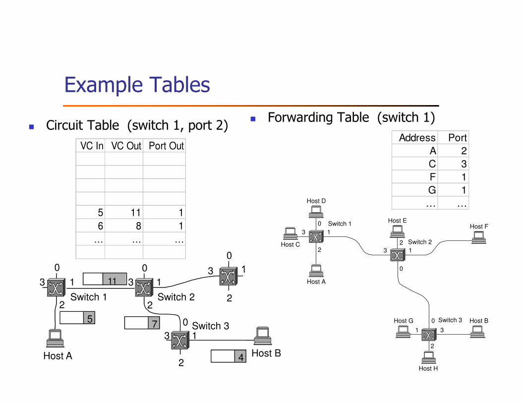
� Each switch maintains a VC table
2
0
1
2
3
0
1
2
3
0
13
0
2
3
Host A Host B
Switch 3
Switch 2Switch 1
75
4
11
Q: how does VC Switching differ from Circuit Switching?
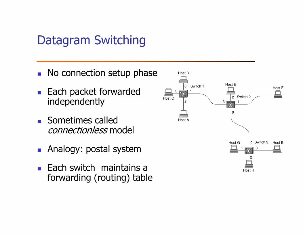
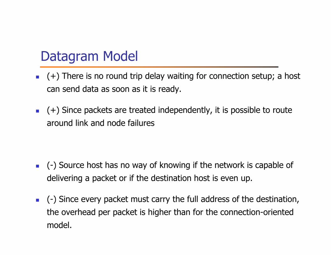
Datagram Switching
� No connection setup phase
� Each packet forwarded independently
� Sometimes called connectionless model
� Analogy: postal system
� Each switch maintains a forwarding (routing) table
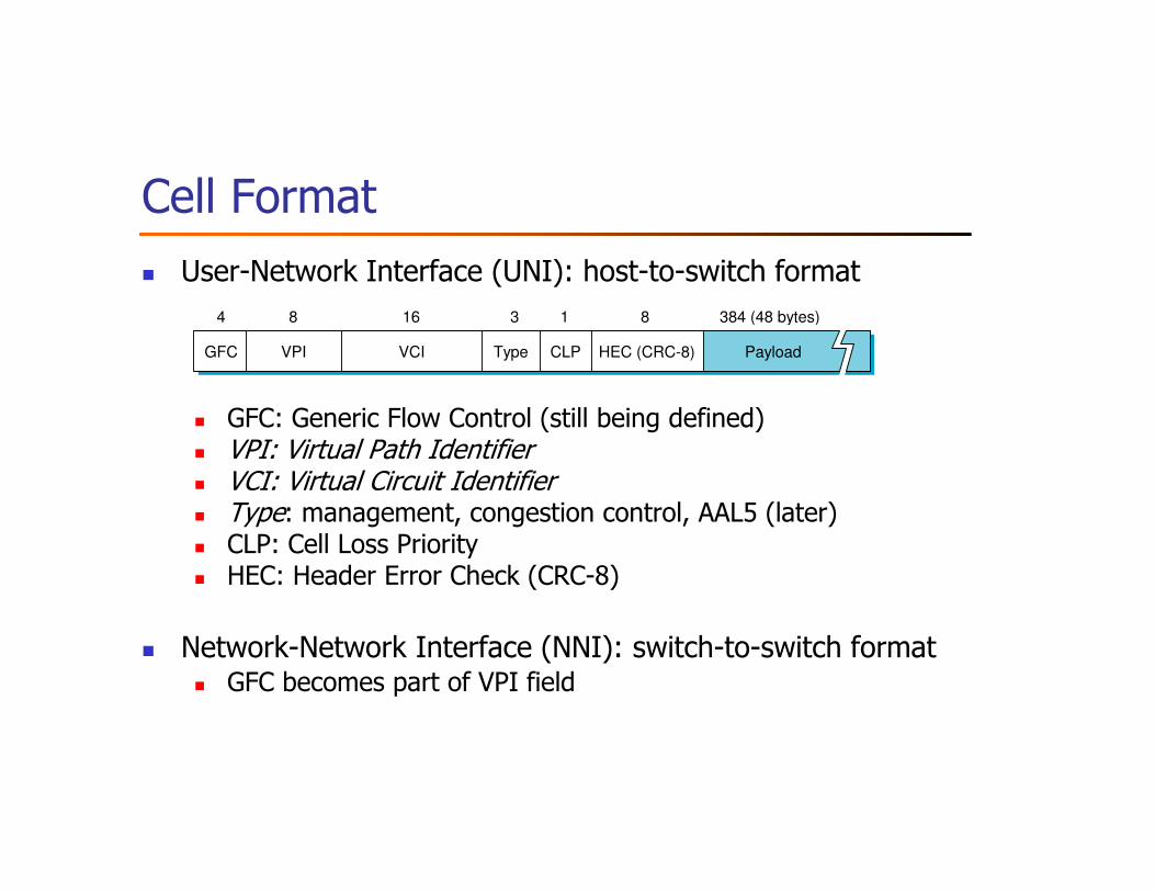
� Network-Network Interface (NNI): switch-to-switch format� GFC becomes part of VPI field
GFC HEC (CRC-8)
4 16 3 18
VPI VCI CLPType Payload
384 (48 bytes)8
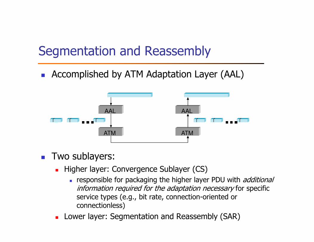
Segmentation and Reassembly
� Accomplished by ATM Adaptation Layer (AAL)
� Two sublayers:
� Higher layer: Convergence Sublayer (CS)
� responsible for packaging the higher layer PDU with additional information required for the adaptation necessary for specific service types (e.g., bit rate, connection-oriented or connectionless)
� Lower layer: Segmentation and Reassembly (SAR)
■■■ ■■■AAL
ATM
AAL
ATM
Different types of AALs
� AAL 1 and 2 designed for applications that need guaranteed rate (e.g., voice, video)
� AAL 3/4 designed for data packet
� AAL 5 is an alternative standard for data packet
AAL 3/4
� Convergence Sublayer Protocol Data Unit (CS-PDU)
� CPI: common part indicator (version field); not used yet
� Btag/Etag: beginning and ending tag (deal with cell corruption)
� BAsize: hint on amount of buffer space to allocate
� Length: size of whole PDU
CPI Btag BASize Pad 0 Etag Len
8 16 0─24 8 8 16< 64 KB8
User data
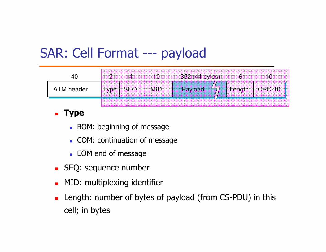
SAR: Cell Format --- payload
� Type
� BOM: beginning of message
� COM: continuation of message
� EOM end of message
� SEQ: sequence number
� MID: multiplexing identifier
� Length: number of bytes of payload (from CS-PDU) in this
cell; in bytes
ATM header Length CRC-10
40 2 4
SEQ MIDType Payload
352 (44 bytes)10 6 10
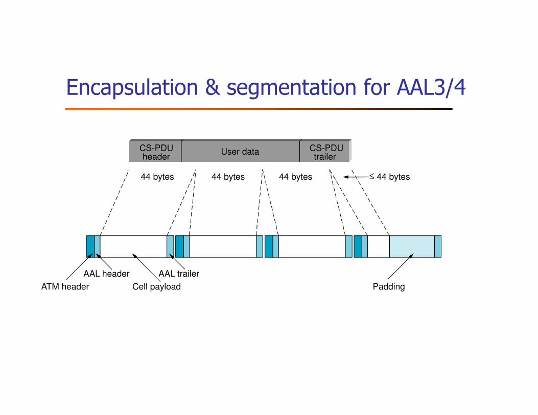
Encapsulation & segmentation for AAL3/4
CS-PDUheader
CS-PDUtrailer
User data
44 bytes 44 bytes 44 bytes ≤ 44 bytes
ATM header
AAL header
Cell payload
AAL trailer
Padding
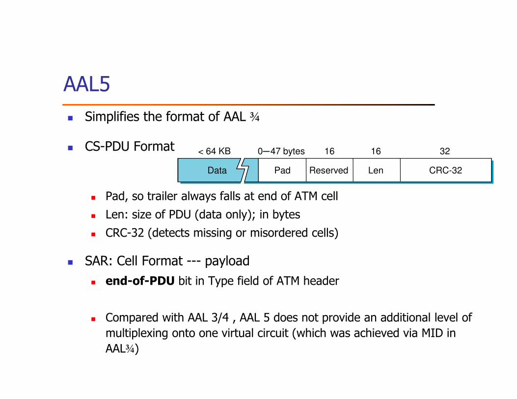
AAL5
� Simplifies the format of AAL ¾
� CS-PDU Format
� Pad, so trailer always falls at end of ATM cell
� Len: size of PDU (data only); in bytes
� CRC-32 (detects missing or misordered cells)
� SAR: Cell Format --- payload
� end-of-PDU bit in Type field of ATM header
� Compared with AAL 3/4 , AAL 5 does not provide an additional level of
multiplexing onto one virtual circuit (which was achieved via MID in
AAL¾)
CRC-32
< 64 KB 0─47 bytes 16 16
ReservedPad Len
32
Data
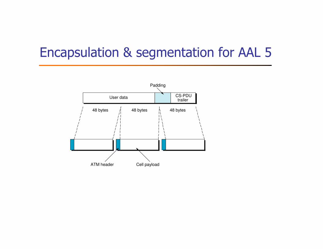
Encapsulation & segmentation for AAL 5
User data
48 bytes 48 bytes 48 bytes
ATM header Cell payload
Padding
CS-PDUtrailer
Virtual path
� Two-level hierarchy of virtual connections
� Virtual path (VP)
� Virtual circuit (VC)
� Switches in public network only maintains state about VPs, which is
much fewer than the number of VCs
� Thus, improves systems scalability
Public network
Network BNetwork A
Outline
� Switching and Forwarding
� Bridges and Extended LANs
� Cell Switching
� Implementation
� Discussion
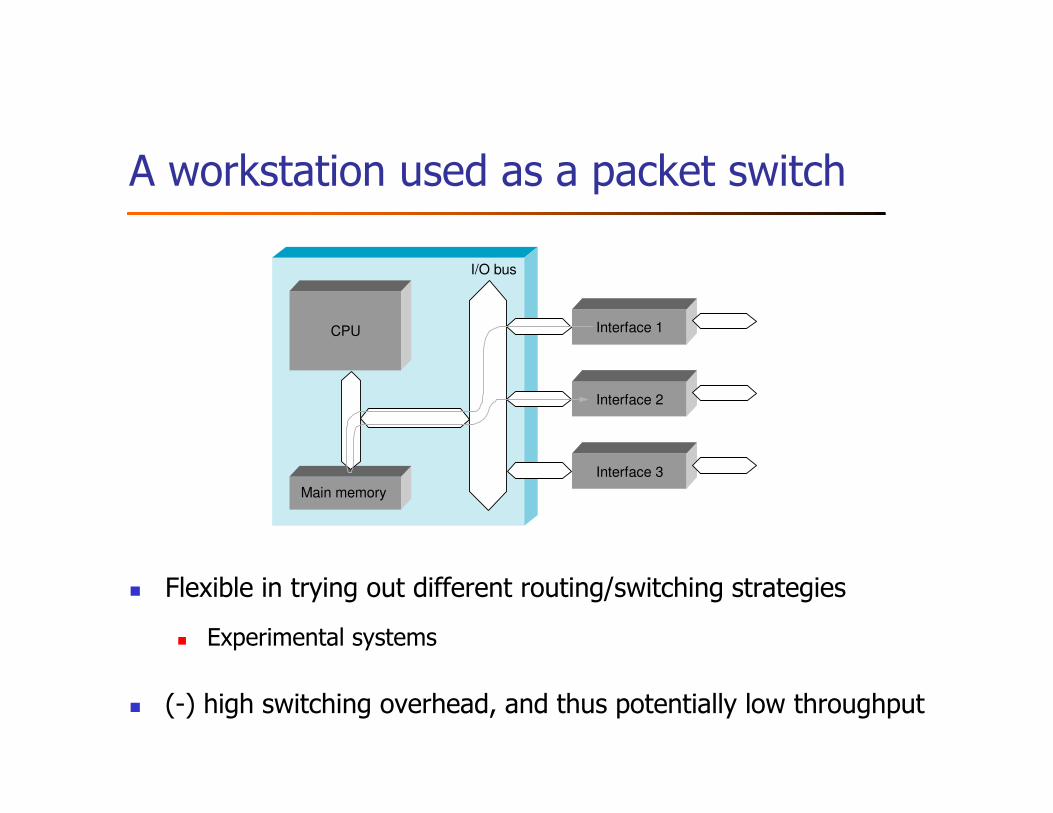
A workstation used as a packet switch
� Flexible in trying out different routing/switching strategies
� Experimental systems
� (-) high switching overhead, and thus potentially low throughput
I/O bus
Interface 1
Interface 2
Interface 3
CPU
Main memory
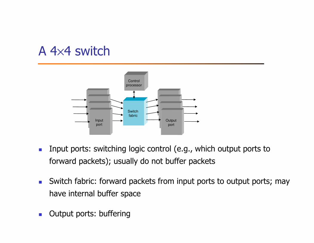
A 4×4 switch
� Input ports: switching logic control (e.g., which output ports to
forward packets); usually do not buffer packets
� Switch fabric: forward packets from input ports to output ports; may
have internal buffer space
� Output ports: buffering
Switchfabric
Controlprocessor
Outputport
Inputport
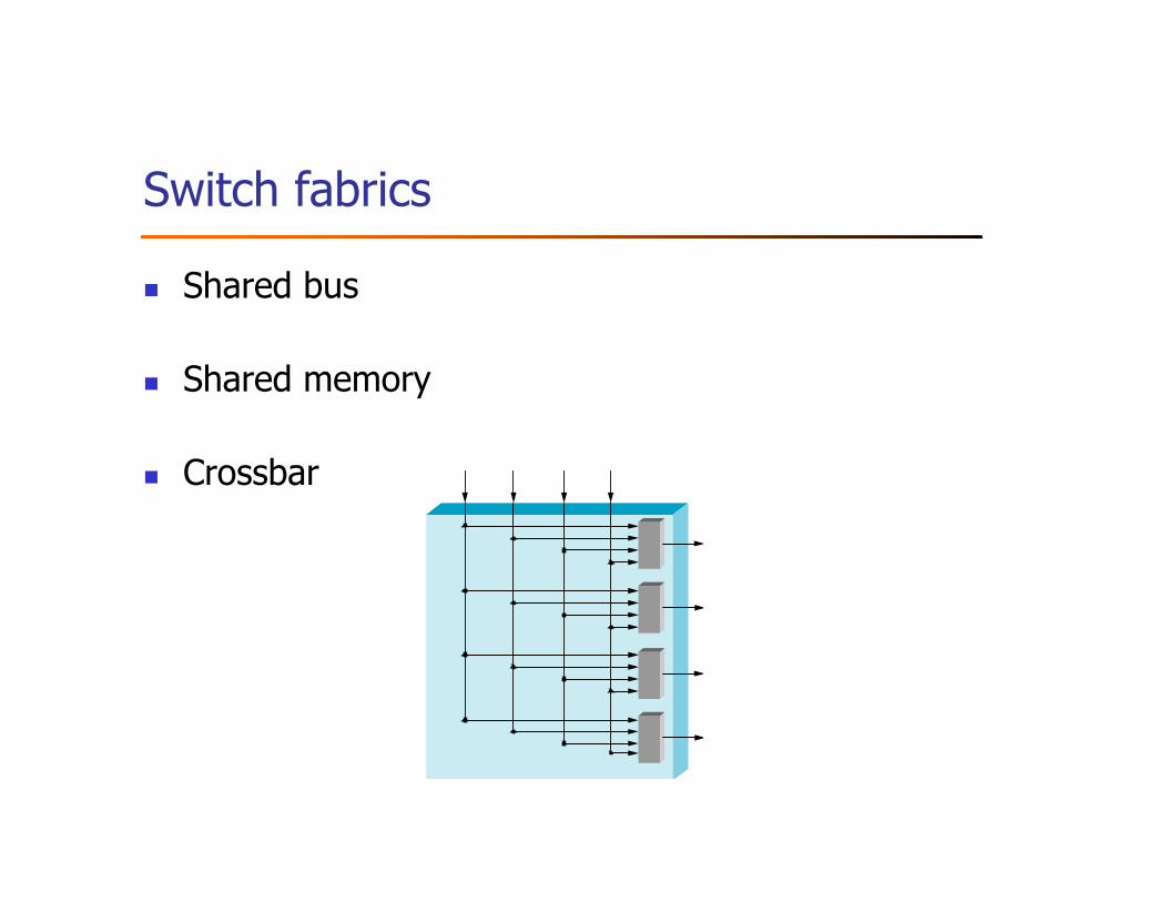
Switch fabrics
� Shared bus
� Shared memory
� Crossbar
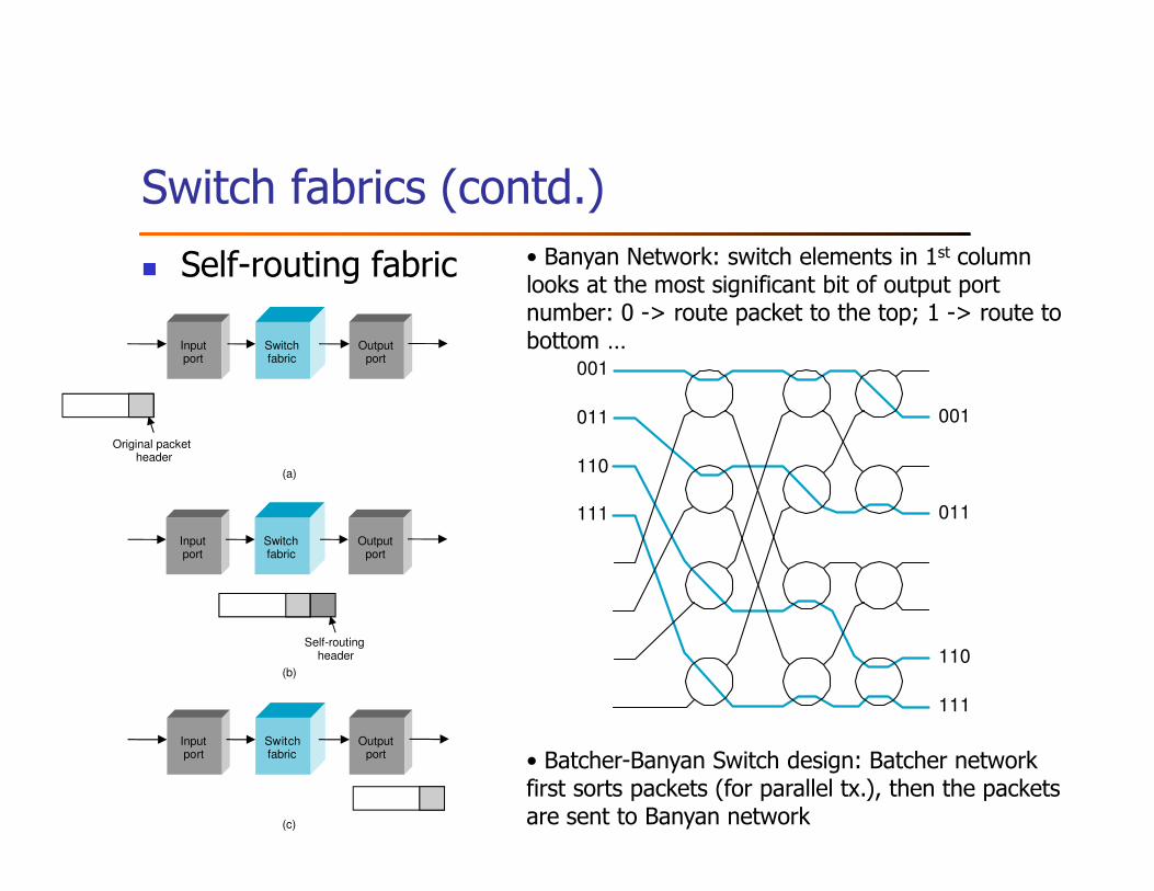
• Banyan Network: switch elements in 1st column looks at the most significant bit of output port number: 0 -> route packet to the top; 1 -> route to bottom …
• Batcher-Banyan Switch design: Batcher network first sorts packets (for parallel tx.), then the packets are sent to Banyan network
Switch fabrics (contd.)
� Self-routing fabric
001
011
110
111
001
011
110
111
Switchfabric
Outputport
Inputport
Original packetheader
Switchfabric
Outputport
Inputport
Self-routingheader
Switchfabric
Outputport
Inputport
(a)
(b)
(c)
Outline
� Switching and Forwarding
� Bridges and Extended LANs
� Cell Switching
� Implementation
� Discussion
Further reading
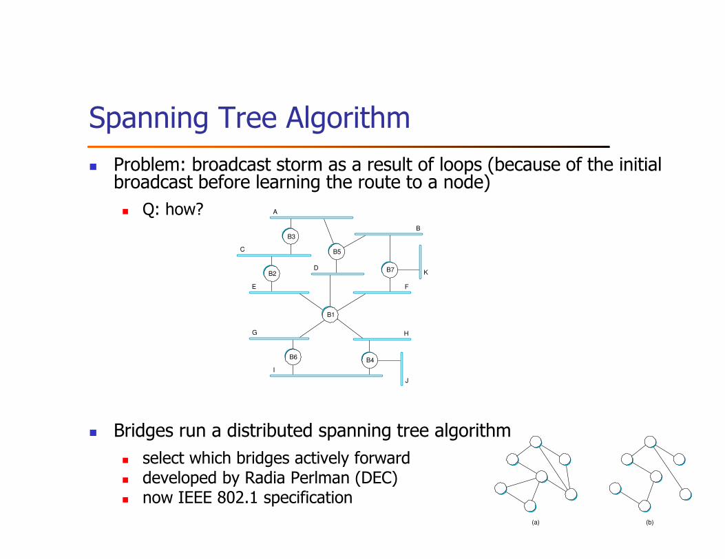
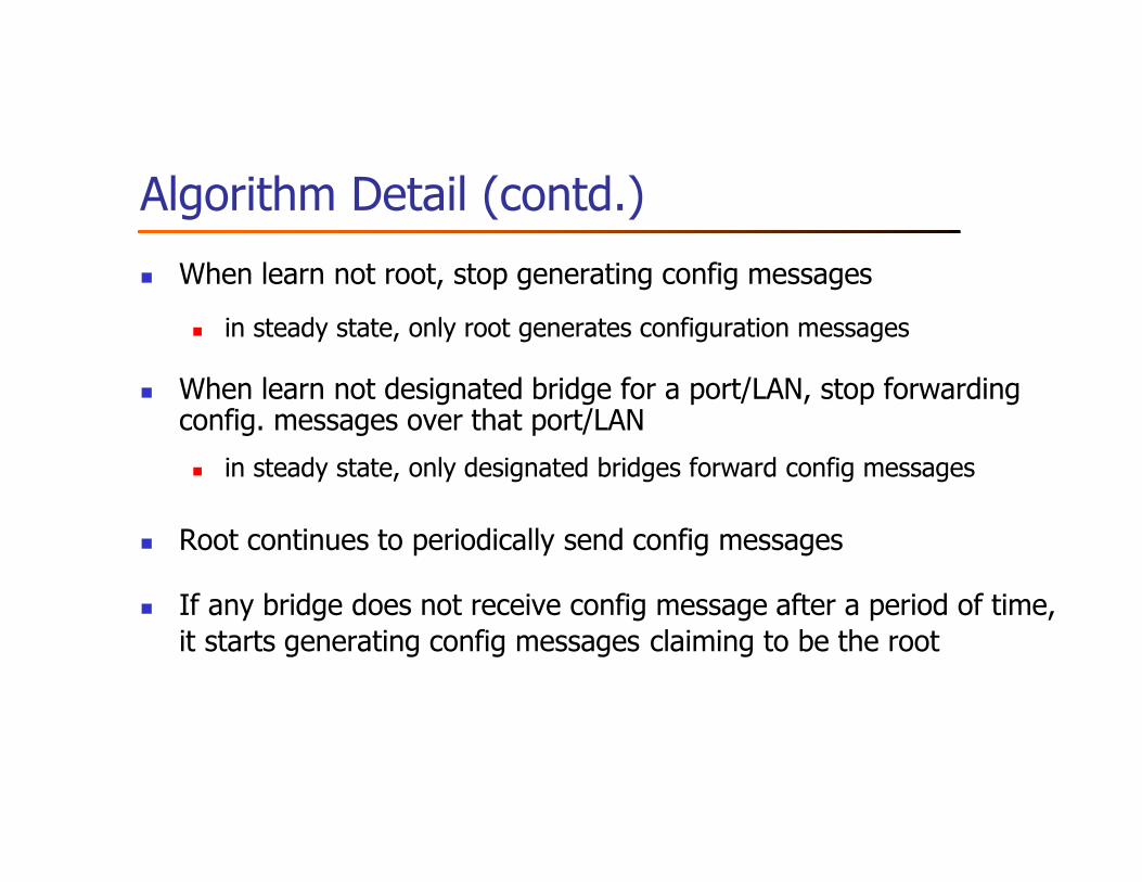
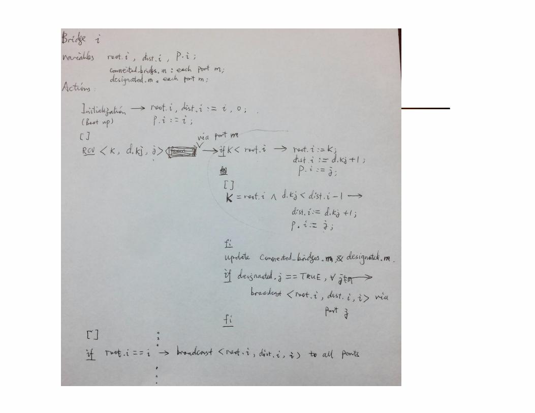
� Spanning tree algorithm
� R. Perlman, “An algorithm for distributed computation of spanning trees in
an extended LAN”, 9th Data Communication Symposium, 1985
� Cell switching
� J. S. Turner, “Design of an integrated services packet network”, 9th Data
Communication Symposium, 1985
� Switch design (e.g., impact of correlated traffic)
� J. N. Giacopelli et al., “Sunshine: A high-performance self-routing
broadband packet-switched architecture”, IEEE Journal of Selected Areas
in Communications (JSAC) 9(8):1289-1298, Oct. 1991
Further reading (contd.)
� Traffic modeling
� W. Leland, M. Taqqu, W. Lillinger, and D. Wilson, “On the
self-similar nature of Ethernet traffic”, IEEE/ACM
Transactions on Networking, 2:1-15, Feb. 1994
� V. Paxson, S. Floyd, “Wide-area traffic: The failure of
Poisson modeling”, ACM SIGCOMM’94
Summary
� Switching and Forwarding
� Bridges and Extended LANs
� Cell Switching
� Implementation
Assignment - Chapter 3
� Exercise#2
� Exercise 1
� Hint: VCI should be unique for each (bidirectional) link
� Exercises 15 and 17
� Exercise 21
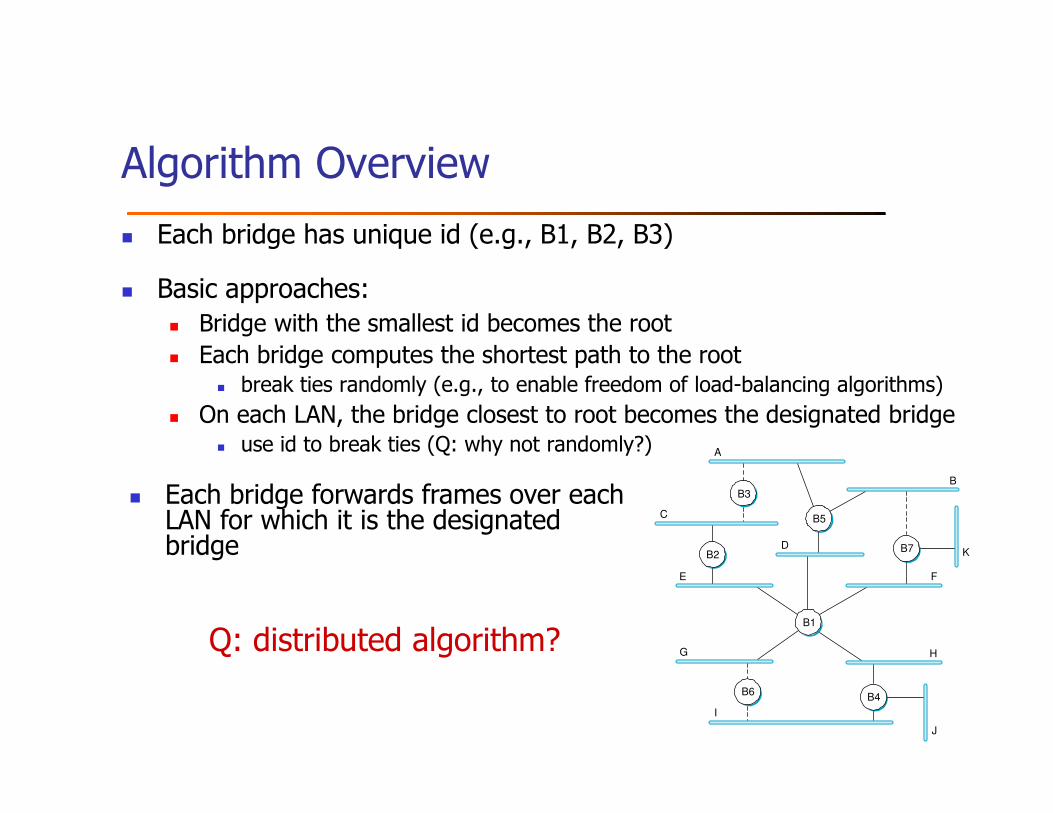
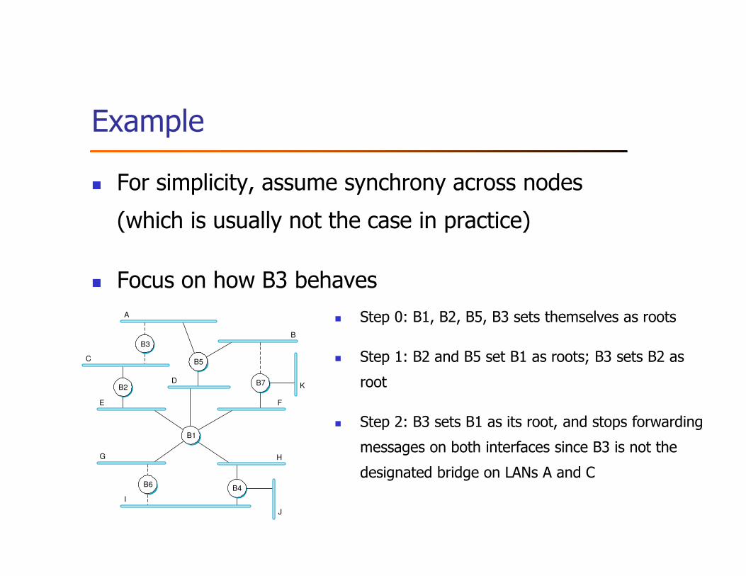
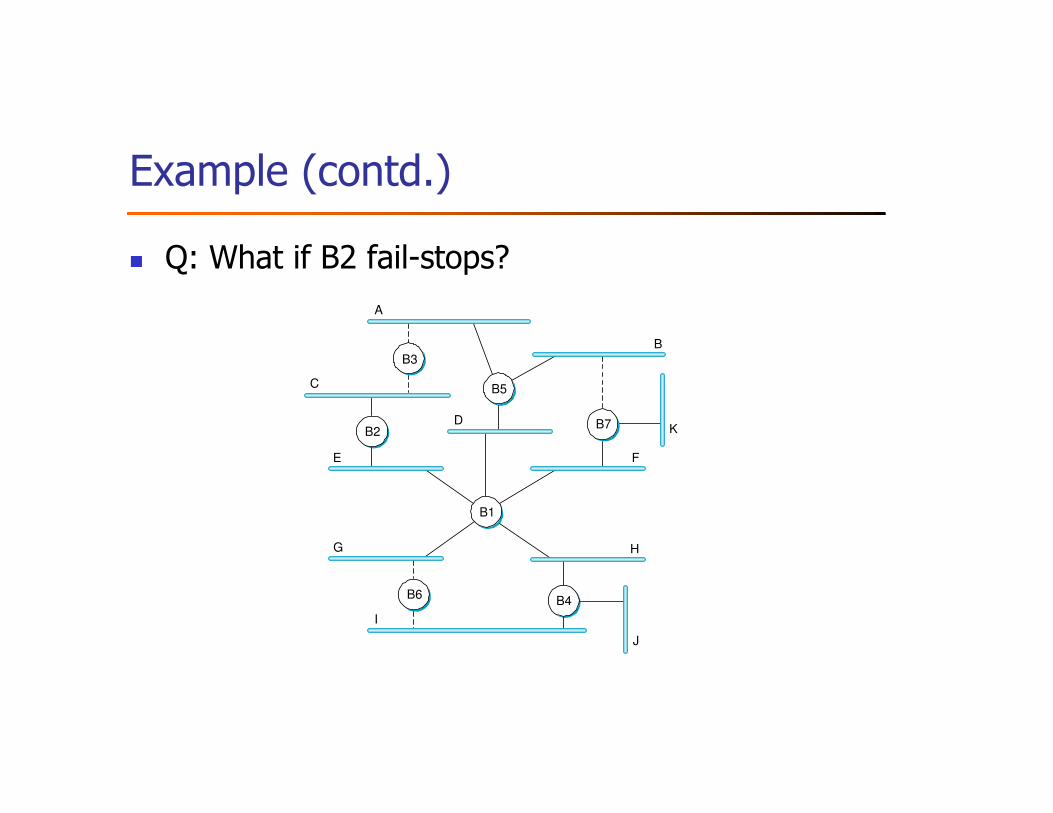
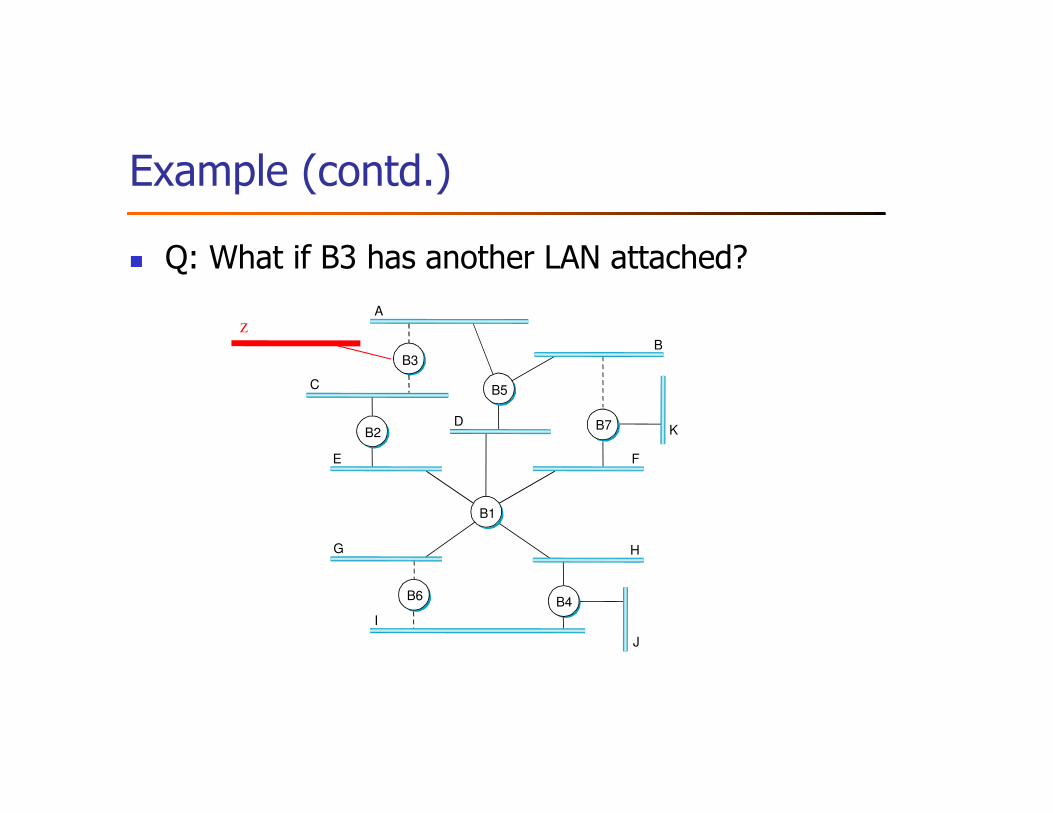
� Hint: for 21 (a), you can regard B1 as a simple repeater that would rebroadcast whatever
messages it receive but does not generate any new message.