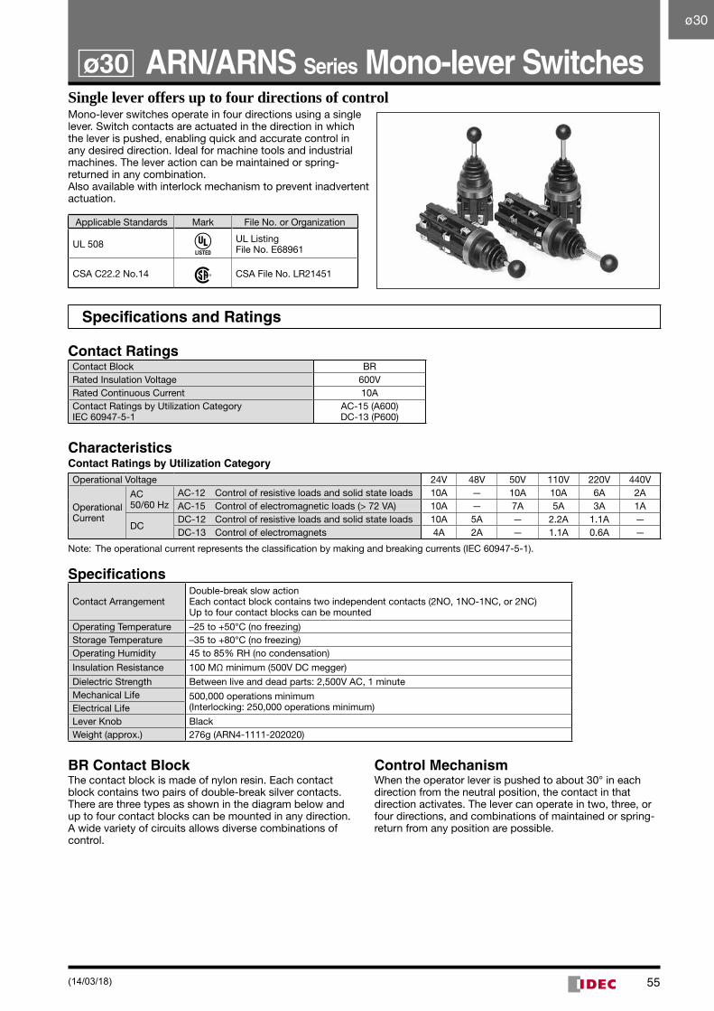
55 Single lever offers up to four directions of control Mono-lever switches operate in four directions using a single lever. Switch contacts are actuated in the direction in which the lever is pushed, enabling quick and accurate control in any desired direction. Ideal for machine tools and industrial machines. The lever action can be maintained or spring- returned in any combination. Also available with interlock mechanism to prevent inadvertent actuation. Applicable Standards Mark File No. or Organization UL 508 UL Listing File No. E68961 CSA C22.2 No.14 CSA File No. LR21451 Specifications and Ratings Contact Ratings Contact Block BR Rated Insulation Voltage 600V Rated Continuous Current 10A Contact Ratings by Utilization Category IEC 60947-5-1 AC-15 (A600) DC-13 (P600) Characteristics Contact Ratings by Utilization Category Operational Voltage 24V 48V 50V 110V 220V 440V Operational Current AC 50/60 Hz AC-12 Control of resistive loads and solid state loads 10A — 10A 10A 6A 2A AC-15 Control of electromagnetic loads (> 72 VA) 10A — 7A 5A 3A 1A DC DC-12 Control of resistive loads and solid state loads 10A 5A — 2.2A 1.1A — DC-13 Control of electromagnets 4A 2A — 1.1A 0.6A — Note: The operational current represents the classification by making and breaking currents (IEC 60947-5-1). Specifications Contact Arrangement Double-break slow action Each contact block contains two independent contacts (2NO, 1NO-1NC, or 2NC) Up to four contact blocks can be mounted Operating Temperature –25 to +50°C (no freezing) Storage Temperature –35 to +80°C (no freezing) Operating Humidity 45 to 85% RH (no condensation) Insulation Resistance 100 MΩ minimum (500V DC megger) Dielectric Strength Between live and dead parts: 2,500V AC, 1 minute Mechanical Life 500,000 operations minimum (Interlocking: 250,000 operations minimum) Electrical Life Lever Knob Black Weight (approx.) 276g (ARN4-1111-202020) BR Contact Block The contact block is made of nylon resin. Each contact block contains two pairs of double-break silver contacts. There are three types as shown in the diagram below and up to four contact blocks can be mounted in any direction. A wide variety of circuits allows diverse combinations of control. Control Mechanism When the operator lever is pushed to about 30° in each direction from the neutral position, the contact in that direction activates. The lever can operate in two, three, or four directions, and combinations of maintained or spring- return from any position are possible. ARN/ARNS Series Mono-lever Switches ø30 ø30 (14/03/18)
Transcript
55
Single lever offers up to four directions of controlMono-lever switches operate in four directions using a single lever. Switch contacts are actuated in the direction in which the lever is pushed, enabling quick and accurate control in any desired direction. Ideal for machine tools and industrial machines. The lever action can be maintained or spring-returned in any combination.Also available with interlock mechanism to prevent inadvertent actuation.
Applicable Standards Mark File No. or Organization
UL 508 UL ListingFile No. E68961
CSA C22.2 No.14 CSA File No. LR21451
Specifications and Ratings
Contact RatingsContact Block BRRated Insulation Voltage 600VRated Continuous Current 10AContact Ratings by Utilization Category IEC 60947-5-1
AC-15 (A600) DC-13 (P600)
CharacteristicsContact Ratings by Utilization CategoryOperational Voltage 24V 48V 50V 110V 220V 440V
Operational Current
AC 50/60 Hz
AC-12 Control of resistive loads and solid state loads 10A — 10A 10A 6A 2AAC-15 Control of electromagnetic loads (> 72 VA) 10A — 7A 5A 3A 1A
DCDC-12 Control of resistive loads and solid state loads 10A 5A — 2.2A 1.1A —DC-13 Control of electromagnets 4A 2A — 1.1A 0.6A —
Note: The operational current represents the classification by making and breaking currents (IEC 60947-5-1).
Specifications
Contact ArrangementDouble-break slow actionEach contact block contains two independent contacts (2NO, 1NO-1NC, or 2NC)Up to four contact blocks can be mounted
Operating Temperature –25 to +50°C (no freezing)Storage Temperature –35 to +80°C (no freezing)Operating Humidity 45 to 85% RH (no condensation)
Insulation Resistance 100 MΩ minimum (500V DC megger)
Dielectric Strength Between live and dead parts: 2,500V AC, 1 minuteMechanical Life 500,000 operations minimum
BR Contact BlockThe contact block is made of nylon resin. Each contact block contains two pairs of double-break silver contacts. There are three types as shown in the diagram below and up to four contact blocks can be mounted in any direction. A wide vari ety of circuits allows diverse combinations of control.
Control MechanismWhen the operator lever is pushed to about 30° in each direction from the neutral position, the contact in that direc tion activates. The lever can operate in two, three, or four directions, and combinations of maintained or spring-return from any position are possible.
ARN/ARNS Series Mono-lever Switchesø30
ø30
(14/03/18)
56
ø30 ARN/ARNS Series Mono-lever Switches
Mono-lever SwitchesOperator Position Lever Action Part No. Dimensions (mm)