Version 2.01 8/29/2001 3.0 CPT8000 System Components The CPT8000 consist of the following components: - Eject Box - Microphone - Mayday Switch Assembly - Antenna - Telematics Control Unit (TCU) - Motorola Timeport TM Cellular Telephone (TDMA or CDMA) with BMW Logo and Software - TCU adapter cable - Compensator (Optional) - RF Cable Adapter (With Compensator Only) - Compensator Cable (With Compensator Only) - CPT8000 Digital Wiring Harness and Connectors Installed in the Vehicle at the Factory The list of components shown above for the CPT8000 is similar to the CPT7000, however the CPT8000 does not utilize a PSE box and uses a digital Timeport TM phone; the software and electronics have changed also. A TCU is used in place of the PSE and a TCU adapter cable is used between the 28-pin connector on the TCU and the 25-pin D-sub that connected to the PSE used for the CPT7000 system. The StarTAC TM phone will not work with the CPT8000 system. A dual push button Mayday switch assembly is located in the headliner near the microphone. It provides direct access to the Emergency and Roadside Assist features. The CPT8000 does not have its own "Voice Activation" circuitry. A 26-pin ELO connector for the SES module is shown in figures 1, 2, 5 and 6 is labeled as number 31. Although the voice recognition system operates in conjunction with the phone system, it is not part of CPT8000 produced by Motorola; therefore the voice recognition system is not discussed in detail in this manual. Except for the compensator, the components of the CPT8000 and CPT7000 are not compatible or interchangeable due to technological differences between the two systems. Some pre-2001 models can be retrofitted with the CPT8000 system if the vehicle has CPT7000 wiring or can be retrofitted with CPT7000 wiring. See section 3.8 for a description and explanation about the Analog to Digital Wiring Conversion Cable and how it interfaces with the CPT7000.
Transcript
Version 2.01 8/29/2001
3.0 CPT8000 System Components
The CPT8000 consist of the following components:
- Eject Box
- Microphone
- Mayday Switch Assembly
- Antenna
- Telematics Control Unit (TCU)
- Motorola TimeportTM Cellular Telephone (TDMA or CDMA) with BMW Logo and Software
- TCU adapter cable
- Compensator (Optional)
- RF Cable Adapter (With Compensator Only)
- Compensator Cable (With Compensator Only)
- CPT8000 Digital Wiring Harness and Connectors Installed in the Vehicle at the Factory
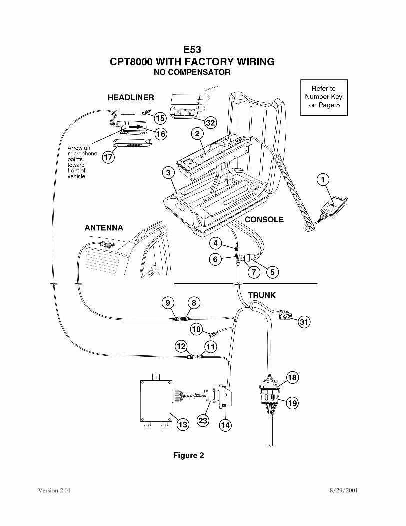
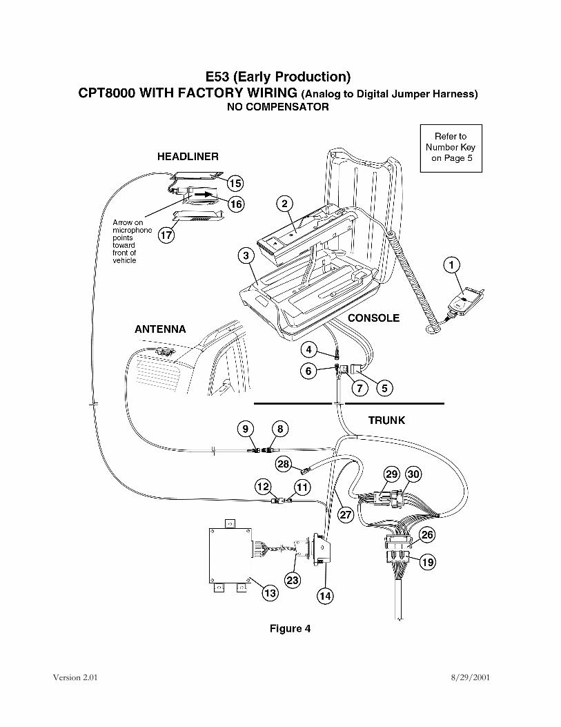
The list of components shown above for the CPT8000 is similar to the CPT7000, however the CPT8000 does not utilize a PSE box and uses a digital TimeportTM phone; the software and electronics have changed also. A TCU is used in place of the PSE and a TCU adapter cable is used between the 28-pin connector on the TCU and the 25-pin D-sub that connected to the PSE used for the CPT7000 system. The StarTACTM phone will not work with the CPT8000 system.
A dual push button Mayday switch assembly is located in the headliner near the microphone. It provides direct access to the Emergency and Roadside Assist features.
The CPT8000 does not have its own "Voice Activation" circuitry. A 26-pin ELO connector for the SES module is shown in figures 1, 2, 5 and 6 is labeled as number 31. Although the voice recognition system operates in conjunction with the phone system, it is not part of CPT8000 produced by Motorola; therefore the voice recognition system is not discussed in detail in this manual.
Except for the compensator, the components of the CPT8000 and CPT7000 are not compatible or interchangeable due to technological differences between the two systems. Some pre-2001 models can be retrofitted with the CPT8000 system if the vehicle has CPT7000 wiring or can be retrofitted with CPT7000 wiring. See section 3.8 for a description and explanation about the Analog to Digital Wiring Conversion Cable and how it interfaces with the CPT7000.
Version 2.01 8/29/2001
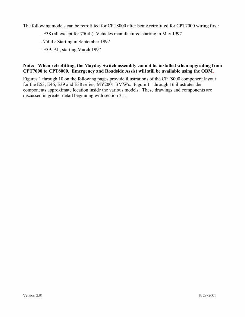
The following models can be retrofitted for CPT8000 after being retrofitted for CPT7000 wiring first:
- E38 (all except for 750iL): Vehicles manufactured starting in May 1997
- 750iL: Starting in September 1997
- E39: All, starting March 1997
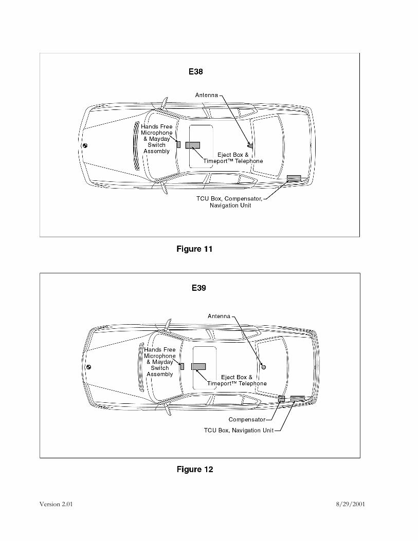
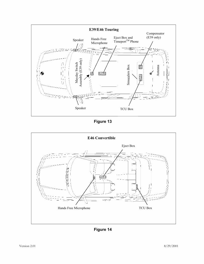
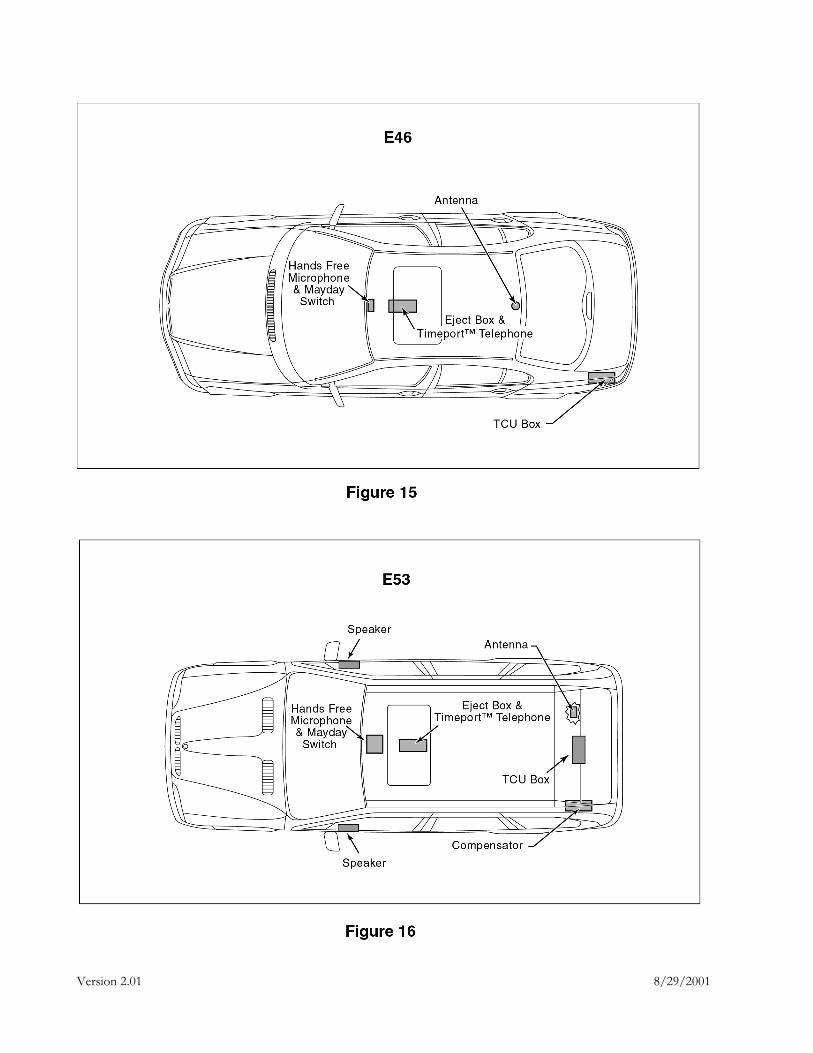
Note: When retrofitting, the Mayday Switch assembly cannot be installed when upgrading from CPT7000 to CPT8000. Emergency and Roadside Assist will still be available using the OBM. Figures 1 through 10 on the following pages provide illustrations of the CPT8000 component layout for the E53, E46, E39 and E38 series, MY2001 BMW's. Figure 11 through 16 illustrates the components approximate location inside the various models. These drawings and components are discussed in greater detail beginning with section 3.1.
Version 2.01 8/29/2001
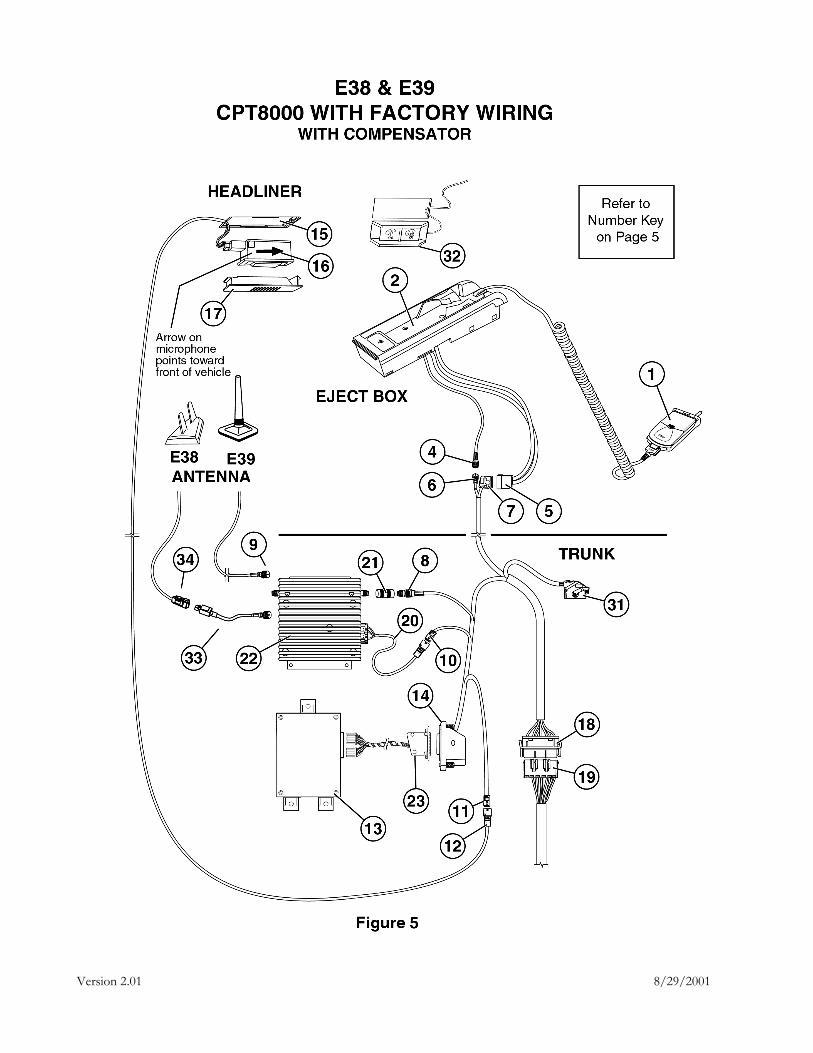
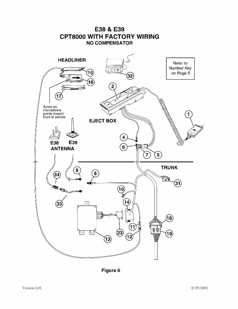
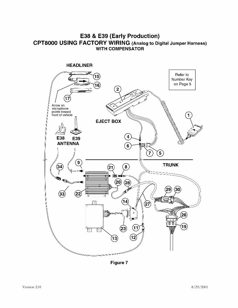
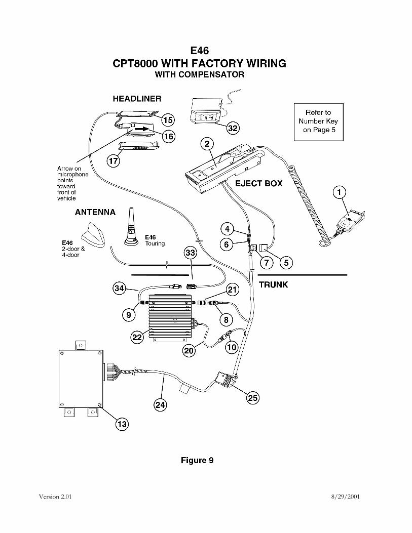
Number Key for Figures 1 through 10 No. Component 1 TimePort™ Handset 2 Eject Box 3 Center Console Arm Rest 4 RF Connector, Female pin 5 18 Pin ELO Connector, Male pins, X4545 6 RF Connector, Male pin (Antenna) 7 18 Pin ELO Connector, Female pins, X4545 8 RF Connector, Female pin 9 RF Connector, Male pin 10 3 Pin Compensator Connector, Female pins, X1765 11 3 Pin Microphone Connector, Female pins, X4221 12 3 Pin Microphone Connector, Male pins, X4221 13 TCU Box, Telematics Control Unit with a 25 Pin D-Sub Connector, Male pins 14 25 Pin D-Sub Connector, Female pins, X18500 15 Location of Microphone in Center Front Headliner 16 Microphone 17 Microphone Cover 18 12 Pin Male Connector, Female pins, X400 19 12 Pin Female Connector, Male pins, X400 20 14 to 3 Pin Adapter Cable that is part of the Optional Compensator Kit 21 RF Interface Connector, Both Male RF pins 22 Compensator, Female pins on Both Connections 23 TCU adapter cable, 25-pin to 28-pin connector on the TCU D-Sub Connector 24 26 Pin ELO Adapter Cable to 28 Pin TCU Multi-Lock Connector, E46 only 25 26 Pin ELO Connector, Female pins, E46 only 26 Same as Number 18 in Figures 1, 2, 5 & 6, but Modified to Convert the CPT6000VR Factory Wiring
for CPT7000 installation (N/A for E46) 27 I-Bus Wire which is part of the Analog to Digital Wiring Conversion Cable; See Figure 12 for a
diagram of the Analog to Digital Wiring Conversion Cable on page 18 (N/A for E46) 28 Same type of Connector and Function as Number 10 in Figures 1, 2, 5, 6, 9 & 10; it is Part of the
Analog to Digital Wiring Conversion Cable (N/A for E46) 29 4 Pin Female Connector of Analog to Digital Wiring Conversion Cable, Male pins (N/A for E46) 30 4 Pin Male Connector of Analog to Digital Wiring Conversion Cable, Female pins (N/A for E46) 31 26 pin SES Male Connector, Female pins, SES Module not shown 32 Mayday Switch Assembly for Emergency and Roadside Assist 33 Fakra Adapter Cable for E38 34 Fakra Male Connector
Version 2.01 8/29/2001
Version 2.01 8/29/2001
Version 2.01 8/29/2001
Version 2.01 8/29/2001
Version 2.01 8/29/2001
Version 2.01 8/29/2001
Version 2.01 8/29/2001
Version 2.01 8/29/2001
Version 2.01 8/29/2001
Version 2.01 8/29/2001
Version 2.01 8/29/2001
Version 2.01 8/29/2001
E39/E46 Touring
Speaker
Speaker TCU Box
Hands Free Microphone
Eject Box and TimeportTM Phone
Compensator (E39 only)
Ant
enna
Smug
gler
s Box
May
day
Switc
h A
ssem
bly
(E39
onl
y)
Figure 13
Eject Box
Hands Free Microphone TCU Box
E46 Convertible
Figure 14
Version 2.01 8/29/2001
Version 2.01 8/29/2001
Version 2.01 8/29/2001
3.1 Eject Box The CPT8000 Eject Box is similar in appearance to the CPT7000 Eject Box, except that it has been slightly modified to accommodate the Motorola TimeportTM handset.
It is installed between the front seats in the console; the E53 eject box is concealed under the armrest in the console as shown in figures 1 through 4. The E38 will have the eject box installed at the factory. The E53 4.4L V8 will have the eject box installed at the factory until April of 2001. After April 2001 it will only have the wiring.
3.2 Microphone The microphone is located in the headliner near the rear view mirror and is shown in figures 1 through 10 and labeled as number 16 in each diagram. For the E38, the microphone will be installed at the factory. The E53 4.4L V8 will have the microphone installed at the factory until April of 2001. After April 2001 it will only have the wiring.
A connector in the headliner attaches to the microphone assembly and ties into the TCU at pins 14, 15 and 20 as shown in the schematic in section 5.4. Assure that the arrow on the microphone is pointing toward front of vehicle when installed.
3.3 Antenna A unique antenna and location are used for each model. Refer to Figures 1 through 10 for the type of antenna used for the various models shown. Figure 11-16 shows the approximate location of the antenna for each model. Refer to the BMW installation guide for part numbers and installation details. The E38 and E53 will have the antenna installed at the factory.
3.4 Telematics Control Unit (TCU) The TCU for the CPT8000 contains the software and electronics that are responsible for processing the voice data and integration of the phone with the vehicle. See figures 1 through 10 for the TCU box and how it ties into the system (labeled as 13 in the drawings).
3.5 Handset The CDMA and TDMA TimeportTM handsets look very similar at a glance, but there are physical and functional differences between the two. It is important to be able to differentiate between the two types in order to avoid customer confusion and dissatisfaction if they receive the incorrect handset for use in their BMW.
Version 2.01 8/29/2001
A Motorola TimeportTM handset is used for the CPT8000 system. Although the TimeportTM handset is available as a portable phone sold separately by various vendors, it will not interface with the BMW vehicle. Only a handset that is included in the CPT8000 phone kit will interface with the BMW vehicle; it can also be used as a portable cellular phone when not interfacing with the vehicle.
The TimeportTM handset is a dual band/tri-mode phone, whereas the StarTACTM handset used with the CPT7000 is a single band/dual mode phone. Both phones operate in the 800 MHz band in analog and digital, modes The TimeportTM, however, also operates in the 1900 MHz band in the digital mode. Both phones are considered to be digital even though they can operate in an analog mode.
NOTE: Parts of CPT7000 and CPT8000 Phones cannot be interchanged.
Two types of handsets are available for the CPT8000. A digital TDMA or CDMA TimeportTM handset can be used which will be determined by the customer and/or carrier availability. The handset plugs into the coil cord that is attached to the eject box in the center console. Refer to figures 1 through 10 for an illustration of the handset in vehicle mode. See figure 18 for physical differences between the TDMA and CDMA TimeportTM phones. Section 4.0 describes CDMA and TDMA functionality differences and similarities.
The customer will have the option to purchase more than one handset that can also be integrated with the same vehicle; only one handset can be integrated at any time. Unlike the CPT7000, however, there is not a primary or secondary phone distinction with the CPT8000. When more than one BMW TimeportTM phone is used with the same vehicle, the phone that is connected to the coil cord is recognized by the TCU and it will use the information stored in that particular phone until it is disconnected from the coil cord. A TimeportTM phone cannot be programmed to be a primary phone as was the case with the CPT7000 StarTACTM phone. All BMW TimeportTM phones are equally functional, regardless of number of users per vehicle, or order of usage.
There will be a separate part number for each type of handset. Reference the Parts Counter Card for the CPT8000 when it is distributed to the BMW center.
3.6 Compensator The compensator is an optional component that is used to "compensate" for the small amount of signal loss in the coaxial cable used to send a signal to the vehicle's antenna from the handset. See figures 1 through 10 for wiring diagrams for the E53, E46, E38 and E39 with and without a compensator as noted under the figure title. The compensator is labeled as number 22 in figures 1, 3, 5, 7 & 9.
An RF interface connector is used to couple two female connectors between the compensator and factory wiring harness side of the RF cable as shown in figures 1, 3, 5, 7, & 9, labeled as number 21. A compensator adapter cable is used between the 14-pin connector on the compensator and the 3-pin
Version 2.01 8/29/2001
connector on the factory wiring harness; the compensator adapter cable is labeled as number 20 in figures 1, 3, 5, 7 & 9.
3.7 Mayday Switch Assembly A dual push button switch assembly is part of the CPT8000 system. It is located in the headliner near the microphone. Refer to the wiring diagrams in figures 1 - 10 for an approximate component and wiring layout for the E53, E46, E39 and E38 models.
These buttons give the user direct access to the Emergency and Roadside Assist features. This eliminates the need for navigating through the OBM menu or making multiple selections using the MID; these features can still be accessed with the OBM or MID, if equipped, in addition to the Mayday switch assembly. The Mayday switch for E38 is installed at the factory.
Vehicles that are retrofitted with the CPT8000 may not have the factory pre-wiring for the Mayday switch available.
Refer to Figures 1 - 10 for wiring diagrams with and without the Mayday switch assembly (labeled as number 32). The E38 will have the Mayday switch installed at the factory.
3.8 Factory Installed Wiring Harness The CPT8000 factory installed wiring for E53, E46, E39 and E38 is similar to the CPT7000 factory installed wiring harness. Additional wiring has been added to support the Mayday switch operation. The installation kit for the CPT8000 will include a TCU adapter cable that will be installed between the 25-pin D-sub connector and 28-pin connector on the TCU.
The E46 still needs the adapter cable between the 26-pin male ELO connector and the 25-pin D-Sub connector. It is still not necessary to install the analog to digital wiring conversion cable for the E46.
For all other vehicles with analog wiring, being retrofitted with the CPT8000, will still need to install the analog-to-digital wiring conversion cable. It will be the same conversion cable that is used with the CPT7000 retrofits. Refer to the parts counter card for the CPT8000 to assure that the correct adapter cables are installed.


![EPM TipsNTricks Consolidated[1]](https://static.documents.pub/doc/80x56/55246b784a7959a2488b4702/epm-tipsntricks-consolidated1.jpg)


