Engineering Design, Construction, and Right-of-Way Acquisition Brookings County – Hampton 3-1 December 2008 3.0 ENGINEERING DESIGN, CONSTRUCTION, AND RIGHT-OF- WAY ACQUISITION 3.1 TRANSMISSION LINE ENGINEERING AND OPERATIONAL DESIGN An HVTL consists of three phases, each at the end of a separate insulator string, all physically supported by structures. Each phase consists of one or more conductors. When more than one conductor is used to make up a phase, the term “bundled” conductors is used. Conductors are metal cables consisting of multiple strands of steel and aluminum wire wound together. There are also two shield wires strung above the electrical phases to prevent damage from lightning strikes. These cables are typically less than one inch in diameter. The shield wire can also include fiber optic cable that allows a path for substation protection equipment to communicate equipment at other terminals on the transmission line. A double circuit transmission line carries two circuits or six phases and normally two shield wires. There are several different types of structures used for transmission lines, including single steel pole structures and H-frame structures. Transmission lines are constructed on a ROW, which is primarily dependent on structure design, span length and the electrical safety requirements associated with the transmission line’s voltage. 3.1.1 TRANSMISSION STRUCTURE DESIGN AND RIGHT-OF-WAY 3.1.1.1 Transmission Structures The Applicants propose to use single pole, self-weathering steel double circuit structures for the majority of the Project (Figure 3-1). Self-weathering steel oxidizes or rusts to form a dark reddish brown surface coating to protect the structure from further weathering. Single steel pole structures are typically placed on a large concrete foundation. Each phase will consist of bundled conductors composed of two 954 ACSS cables or conductors of comparable capacity. Each conductor is 954,000 circular mils or approximately 1.2 inches in diameter. ACSS stands for Aluminum Conductor Steel Supported and consists of seven steel wires at the center surrounded by 54 aluminum strands. Applicants propose to use the same conductor and bundled configuration for all the 345 kV single circuit and double circuit transmission line sections. Specialty structures, including H-frame poles, may be required in certain limited circumstances. For example, H-frame structures are sometimes required near environmentally sensitive areas, including areas of significant bird activity. H-frames are also used for long spans in some instances. These structures consist of two wooden or steel poles with cross bracing. Concrete pier foundations may be used for angle structures or if soil conditions are poor. At the West Belle Plaine and Redwood River crossings, steel H-frame triple circuit structures may also be used. For the Project 115 kV routes to connect the existing Minnesota Valley – New Ulm 115 kV transmission line with the new Cedar Mountain Substation, single pole wood or steel 115 kV horizontal post transmission lines would be constructed. Table 3-1 summarizes the structure designs and foundations for the single pole structures that will be used for the majority of the Project. Information about specialty structures, such as H-frames and triple-circuit, is also provided.
Transcript
Engineering Design, Construction, and Right-of-Way Acquisition
Brookings County – Hampton 3-1 December 2008
3.0 ENGINEERING DESIGN, CONSTRUCTION, AND RIGHT-OF-WAY ACQUISITION
3.1 TRANSMISSION LINE ENGINEERING AND OPERATIONAL DESIGN
An HVTL consists of three phases, each at the end of a separate insulator string, all physically supported by structures. Each phase consists of one or more conductors. When more than one conductor is used to make up a phase, the term “bundled” conductors is used. Conductors are metal cables consisting of multiple strands of steel and aluminum wire wound together. There are also two shield wires strung above the electrical phases to prevent damage from lightning strikes. These cables are typically less than one inch in diameter. The shield wire can also include fiber optic cable that allows a path for substation protection equipment to communicate equipment at other terminals on the transmission line. A double circuit transmission line carries two circuits or six phases and normally two shield wires. There are several different types of structures used for transmission lines, including single steel pole structures and H-frame structures. Transmission lines are constructed on a ROW, which is primarily dependent on structure design, span length and the electrical safety requirements associated with the transmission line’s voltage.
3.1.1 TRANSMISSION STRUCTURE DESIGN AND RIGHT-OF-WAY
3.1.1.1 Transmission Structures
The Applicants propose to use single pole, self-weathering steel double circuit structures for the majority of the Project (Figure 3-1). Self-weathering steel oxidizes or rusts to form a dark reddish brown surface coating to protect the structure from further weathering. Single steel pole structures are typically placed on a large concrete foundation.
Each phase will consist of bundled conductors composed of two 954 ACSS cables or conductors of comparable capacity. Each conductor is 954,000 circular mils or approximately 1.2 inches in diameter. ACSS stands for Aluminum Conductor Steel Supported and consists of seven steel wires at the center surrounded by 54 aluminum strands. Applicants propose to use the same conductor and bundled configuration for all the 345 kV single circuit and double circuit transmission line sections.
Specialty structures, including H-frame poles, may be required in certain limited circumstances. For example, H-frame structures are sometimes required near environmentally sensitive areas, including areas of significant bird activity. H-frames are also used for long spans in some instances. These structures consist of two wooden or steel poles with cross bracing. Concrete pier foundations may be used for angle structures or if soil conditions are poor. At the West Belle Plaine and Redwood River crossings, steel H-frame triple circuit structures may also be used.
For the Project 115 kV routes to connect the existing Minnesota Valley – New Ulm 115 kV transmission line with the new Cedar Mountain Substation, single pole wood or steel 115 kV horizontal post transmission lines would be constructed.
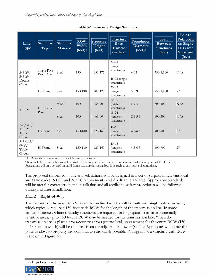
Table 3-1 summarizes the structure designs and foundations for the single pole structures that will be used for the majority of the Project. Information about specialty structures, such as H-frames and triple-circuit, is also provided.
Engineering Design, Construction, and Right-of-Way Acquisition
Brookings County – Hampton 3-2 December 2008
Figure 3-1. 345 kV Double Circuit Single Pole Structure
Engineering Design, Construction, and Right-of-Way Acquisition
a ROW width depends on span length between structures. b It is unlikely that foundations will be used for H-frame structures as these poles are normally directly imbedded. Concrete foundations will only be used on an H-frame structure in special locations such as very poor soil conditions.
The proposed transmission line and substations will be designed to meet or surpass all relevant local and State codes, NESC and NERC requirements and Applicant standards. Appropriate standards will be met for construction and installation and all applicable safety procedures will be followed during and after installation.
3.1.1.2 Right-of-Way
The majority of the new 345 kV transmission line facilities will be built with single pole structures, which typically require a 150-foot-wide ROW for the length of the transmission line. In some limited instances, where specialty structures are required for long spans or in environmentally sensitive areas, up to 180 feet of ROW may be needed for the transmission line. When the transmission line is placed cross-country across private land, an easement for the entire ROW (150 to 180 feet in width) will be acquired from the adjacent landowner(s). The Applicants will locate the poles as close to property division lines as reasonably possible. A diagram of a structure with ROW is shown in Figure 3-2.
Engineering Design, Construction, and Right-of-Way Acquisition
Brookings County – Hampton 3-4 December 2008
Figure 3-2. Double Circuit 345 kV Structure with ROW
When the transmission line parallels other existing infrastructure ROW (e.g., roads, railroads, other utilities), an easement of lesser width may be required as parts of the ROW of the existing infrastructure can often be combined with the ROW needed for the transmission line. When paralleling existing ROW, the Applicants’ typical practice is to place the poles on adjacent private property, a few feet off the existing ROW. With this pole placement, the transmission line shares the existing ROW, thereby reducing the size of the easement required from the private landowner. For example, if required ROW is 150 feet and the pole is placed five feet off of an existing road ROW, only an 80-foot easement would be required from the landowner and the additional 70 feet of the needed ROW would be shared with the road ROW. The arms on the pole would be approximately 85 feet above the ground depending on span length, and extend approximately 18 feet from the center of the pole. In each instance of sharing ROW, the Applicants will acquire necessary approvals from the ROW owner (e.g. railroad) or the agency overseeing use of a particular ROW (e.g. Minnesota Department of Transportation (“MnDOT”) for State trunk highways, including U.S. Highways and Interstates.
Throughout the route development process, the Applicants have sought to identify areas to share ROW with existing infrastructure, including transmission lines, highways and railroad ROW. This approach implements the State’s policy of non-proliferation. In the context of transmission line siting, the non-proliferation policy creates a preference for placing new power lines near existing infrastructure as a way to minimize the proliferation of new corridors. The PPSA, Minnesota Statutes Chapter 216E, and the Commission’s implementing routing rules recognize this preference and call upon the Commission to consider the utilization of existing railroad and highway ROW as well as any existing transmission corridors in selecting transmission line routes. People for Envtl.
Engineering Design, Construction, and Right-of-Way Acquisition
Brookings County – Hampton 3-5 December 2008
Enlightenment and Responsibility (PEER), Inc. v. Minnesota Envtl. Quality Council, 266 N.W.2d 858 (Minn. 1978).
Among the potential ROW sharing opportunities identified for the Alternate Route is along Interstate 35. The Alternate Route parallels Interstate 35 for approximately seven miles between 57th Street West and the Lake Marion Substation area. MnDOT requires that a utility obtain a Utility Permit to construct transmission facilities along, across or in State trunk highways (interstate and non-interstate). Minn. Rule 8810.3300, Subp. 1. As a State agency that will need to issue a permit in connection with the construction of the transmission line, MnDOT must participate in the routing hearings and clearly state whether the proposed facility complies with State standards, rules and policies. Minn. Stat. Section 216E.10, subd. 3.
The Applicants have encouraged MnDOT’s active participation in this process. Prior to filing this Application, the Applicants held several meetings with MnDOT representatives to discuss the proposed alignment of the transmission facilities adjacent to highways. MnDOT representatives have expressed concern over the installation of the transmission line too near the road ROW along Interstate 35. Applicant Xcel Energy has also been meeting with MnDOT representatives as well as representatives from the Federal Highway Administration (“FHWA”) regarding the Fargo – Twin Cities 345 kV project and the potential routing of transmission facilities along Interstate 94. MnDOT has advised the Applicants that any encroachment of the interstate ROW, including arm overhang or the swing of the conductors under extreme weather and line loading conditions, would require an exception to MnDOT policy, specifically MnDOT’s Procedures for Accommodation of Utilities on Highway Right of Way (November 8, 2005) (“Accommodation Policy”). MnDOT has further stated that FHWA would need to concur for an exception to be granted to allow sharing of ROWs.
The Applicants are continuing discussions with FHWA and MnDOT on these issues in an effort to clarify the situation. Because of the uncertainty regarding viable alignments along Interstate 35, the Applicants have included information about the potential impacts of the transmission facilities along several road alignments for the Interstate 35 segment. The alignments are based on distances of the transmission centerline from the road ROW, at five feet, 25 feet, and 75 feet (see Appendix E.4). Each of these alignment alternatives results in different impacts on the existing land uses and environment. The data are provided in this comparative format to inform stakeholders and the Commission of the potential impacts associated with placement of the poles, depending on where the alignment occurs in relationship to MnDOT’s ROW.
3.1.2 DESIGN OPTIONS TO ACCOMMODATE FUTURE EXPANSION
The Brookings County – Hampton 345 kV Project is designed to meet future transmission system needs throughout the Project area. Approximately 123 to 136 miles of the 345 kV transmission line will be constructed with double circuit capable poles so that a second circuit can be strung when conditions justify expansion, maximizing the use of the existing ROW and minimizing construction time for a new circuit (114 to 127 miles will be constructed on double circuit poles with both circuits operational upon installation). Similarly, the new substations will be designed to enable additional future transmission line connections.
The forward looking, “upsized” design for these 345 kV sections was developed during the Certificate of Need proceeding. In their August 2007 Certificate of Need application, the Applicants initially proposed that the Lyon County – Cedar Mountain – Helena 345 kV sections be built as double circuit 345 kV, and that the Brookings County – Lyon County and Lyon County – Hazel Creek sections on the west end and the Helena – Lake Marion – Hampton sections on the east end
Engineering Design, Construction, and Right-of-Way Acquisition
Brookings County – Hampton 3-6 December 2008
be constructed as single circuit 345 kV. Also as part of the initial proposal, the Hazel Creek – Minnesota Valley section was to be constructed as single circuit 230 kV.
In the course of the proceedings, preliminary study results indicated that the existing Minnesota Valley – Blue Lake 230 kV transmission line should be rebuilt at 345 kV to accommodate additional generation deliveries from the Buffalo Ridge region to the Twin Cities. Based on these study results, the Applicants concluded that the Hazel Creek to Minnesota Valley section should be constructed as a single circuit 345 kV transmission line with double circuit capability (to match the voltage and size of the anticipated Minnesota Valley – Blue Lake 230 kV rebuild project), but initially operated at 230 kV until other upgrades in the area have been completed.
Later, the Applicants proposed an “upsized” proposal for all single circuit portions of the Project. The Applicants concluded that it would be most appropriate to build the single circuit sections of the Project with larger structures that can be modified to accommodate a second circuit in the future - as double circuit 345 kV rather than single circuit 345 kV.
This “upsized” proposal is the proposal currently under consideration by the Administrative Law Judge in the Certificate of Need proceeding. The Department of Commerce, Office of Energy Security (“OES”) and the parties representing various wind generation development interests, Wind on the Wires, Izaak Walton League of America – Midwest Office, Minnesota Center for Environmental Advocacy and Fresh Energy, sponsored testimony supporting the upsized proposal. The Commission’s decision in the Certificate of Need proceeding is expected in spring 2009.
The Applicants believe that the “upsized” transmission line proposal best meets the near-term generation outlet, regional reliability, generation outlet, and load serving needs while providing flexibility and capability for expansion to meet future needs. Additionally, in this Application, potential locations for several new substations have been identified. Applicants will acquire approximately 40 acres for each of the new substations to ensure there is adequate room for the required facilities, a buffer and future transmission line interconnections.
3.2 IDENTIFICATION OF EXISTING CORRIDORS
Existing utility and public ROW were identified in the route selection process. Table 3-2 provides a summary of the corridor sharing along the proposed routes. The data for the route options are provided in Appendix C.
Table 3-2. Summary of Length of Existing ROW, Survey Lines, Natural Division Lines, and Agricultural Field Boundaries Paralleling the Proposed Routes*
ROW Type Route Route Length Transmission
Line Road Railroad Pipeline
Field Lines
None Total Paralleled
Length
% of Length
Paralleled
Preferred Route 237 39 138 1 2 41 16 221 93.4
Alternate Route 262 33 150 0 0 62 17 245 93.5
*All figures are in miles.
Engineering Design, Construction, and Right-of-Way Acquisition
Brookings County – Hampton 3-7 December 2008
3.3 RIGHT-OF-WAY ACQUISITION, CONSTRUCTION, RESTORATION AND
MAINTENANCE PROCEDURES
3.3.1 RIGHT-OF-WAY ACQUISITION
The ROW acquisition process begins early in the detailed design process. For transmission lines, utilities typically acquire easement rights to accommodate the facilities. The evaluation and acquisition process includes title examination, initial owner contacts, survey work, document preparation and purchase. Each of these activities, particularly as it applies to easements for transmission line facilities, is described in more detail below.
The first step in the ROW process is to identify all persons and entities that may have a legal interest in the real estate upon which the facilities will be built. To compile this list, a ROW agent or other persons engaged by the Applicants will complete a public records search of all land involved in the Project. A title report is then developed for each parcel to determine the legal description of the property and the owner(s) of record of the property and to gather information regarding easements, liens, restrictions, encumbrances and other conditions of record.
The next step is evaluation of the specific parcel. After owners are known, and typically after a Route Permit is issued, a ROW representative contacts each property owner or the property owner’s representative. The ROW agent describes the need for the transmission facilities, how the specific project may affect each parcel, and seeks information from the landowner about any specific construction concerns. The ROW agent may also request the owner’s permission for survey crews to enter the property to conduct preliminary survey work. Permission may also be requested to take soil borings to assess soil conditions and determine appropriate foundation design. Surveys are conducted to locate ROW corridors, natural features, man-made features and associated elevations used during the detailed engineering of the transmission line. The soil analysis is performed by an experienced geotechnical testing laboratory.
During the evaluation process, the proposed transmission line’s location will be staked. This means that the survey crew locates each structure or pole on the ground and marks it with a surveyor’s stake. The ROW agent shows the landowner exactly where the structure(s) will be located on the property as well as delineates the boundaries of easement area required for safe operation of the line.
The ROW agent then negotiates with the property owner(s) to determine the amount of just compensation for the rights to build, operate and maintain the transmission facilities within the easement area and reasonable access to the easement area. The agent also provides maps of the transmission line route or site and the landowner’s parcel and offers compensation for the transmission line easement. In the event that a complicated appraisal problem arises, an appraisal is completed by the utility’s representative(s) to determine the value of the land rights being acquired. The landowner is allowed a reasonable amount of time to consider the offer and present any material that the owner believes is relevant to determining the property’s value.
If the landowner desires a second opinion on the fair market value of the property, the landowner may have an appraisal made. The landowner is reimbursed up to $500 toward the appraiser fee as long as the appraisal follows standard and accepted appraisal practices (Minn. Stat. § 117.189).
In nearly all cases, utilities are able to work with the landowners to address their concerns and an agreement is reached for the utilities’ purchase of land rights. The ROW agent prepares all of the documents required to complete each transaction. Required documents may include: easement, purchase agreement or contract and deed.
Engineering Design, Construction, and Right-of-Way Acquisition
Brookings County – Hampton 3-8 December 2008
In rare instances, if a negotiated settlement cannot be reached, the landowner may choose to have an independent third party determine the value of the land acquisition. Such valuation is made through the utility’s exercise of the right of eminent domain pursuant to Minnesota Statutes Chapter 117. The process of exercising the right of eminent domain is called condemnation.
In the event of a condemnation, the utility will provide the landowner with a copy of each appraisal it has obtained for the property interests. To start the condemnation process, a utility files a petition in the district court where the property is located and serves that petition on all owners of the property. If the court approves the petition, the court then appoints a three-person condemnation “commission.” The three people appointed must be knowledgeable of applicable real estate issues. Once appointed, the commissioners schedule a viewing of the property over and across which the transmission line easement is to be located. Next, the commission schedules a valuation hearing where the utility and landowners can testify as to the fair market value of the easement or fee. The commission then makes an award as to the value of the property acquired and files it with the court. Each party has 40 days from the award filing to appeal to the district court for a jury trial. In the event of an appeal, the jury hears land value evidence and renders a verdict. At any point in this process, the case can be dismissed if the parties reach a settlement.
Once ROW is acquired and prior to construction, the ROW agent will again contact the owner of each parcel to discuss the construction schedule and requirements. To ensure safe construction of the transmission line, special consideration may be needed for fences, crops or livestock. For instance, fences may need to be moved or temporary or permanent gates may need to be installed; crops may need to be harvested early; and livestock may need to be moved. In each case the ROW agent coordinates these processes with the landowner, who is compensated for damages.
3.3.2 CONSTRUCTION PROCEDURES
Construction will begin after all federal, State and local approvals are obtained, property and ROWs are acquired, soil conditions are established and final design is completed. The precise timing of construction will consider various requirements that may be in place due to permit conditions, system loading issues and available workforce.
The actual construction will follow standard construction and mitigation best practices that were developed from past project experience. These best practices address ROW clearing, staging, erecting transmission line structures and stringing transmission lines. Construction and mitigation practices to minimize impacts will be developed based on the proposed schedule for activities, permit requirements, prohibitions, maintenance guidelines, inspection procedures, terrain and other practices. In some cases these activities, such as schedules, are modified to minimize impacts to sensitive environments.
Transmission line structures are generally designed for installation at existing grades. Typically, structure sites with 10 percent or less slope will not be graded or leveled. At sites with more than 10 percent slope, working areas will be graded level or fill will be brought in for working pads. If the landowner permits, it is preferred to leave the leveled areas and working pads in place for use in future maintenance activities, if any. If the landowner does not wish to leave the leveled area, the site is graded back to its original condition as much as possible and all imported fill is removed.
Typical project construction equipment consists of tree removal equipment, mowers, cranes, backhoes, digger-derrick line trucks, track-mounted drill rigs, dump trucks, front end loaders, bucket trucks, bulldozers, flatbed tractor-trailers, flatbed trucks, pickup trucks, concrete trucks and various
Engineering Design, Construction, and Right-of-Way Acquisition
Brookings County – Hampton 3-9 December 2008
trailers. Many types of excavation equipment are set on wheel or track-driven vehicles. Poles are transported on tractor-trailers.
Staging areas will be established for the Project and involves delivering the equipment and materials necessary to construct the new transmission line facilities. The materials will be stored at staging areas until they are needed for construction.
Temporary lay down areas may be required for additional storage space during construction. These areas will be selected for their location, access, security and ability to efficiently and safely warehouse supplies. The areas are chosen to minimize excavation and grading. The temporary lay down areas outside of the transmission line ROW will be obtained from affected landowners through rental agreements.
Access to the transmission line ROW corridor is made directly from existing roads or trails that run parallel or perpendicular to the transmission line ROW. In some situations, private field roads or trails are used. Permission from the property owner is obtained prior to accessing the transmission line route. Where necessary to accommodate the heavy equipment used in construction—including cranes, cement trucks and hole drilling equipment—existing access roads may be upgraded or new roads may be constructed. New access roads may also be constructed when no current access is available or the existing access is inadequate to cross roadway ditches.
When it is time to install the poles, they are generally moved from the staging areas and delivered to the staked location. The structures are typically placed within the transmission line ROW until the structure is set. Insulators and other hardware are attached while the pole is on the ground. The pole is then lifted, placed and secured using a crane. Figure 3-3 shows insulator installation.
Figure 3-3. Insulator Installation
Medium angle, heavy angle or dead-end structures will have concrete foundations. In those cases, holes are drilled in preparation for concrete. Drilled pier foundations may vary from 5 to 7 feet in diameter for the 345 kV transmission line and 2.5 to 3.5 feet for the 115 kV transmission line, and
Engineering Design, Construction, and Right-of-Way Acquisition
Brookings County – Hampton 3-10 December 2008
12 or more feet deep, depending on soil conditions. After the concrete foundation is set, the pole is bolted to it. Concrete trucks are required to bring concrete from a local concrete batch plant. Tangent and light angle structures may be placed on poured concrete foundations or directly embedded, which involves digging a hole for each pole, filling it partially with crushed rock and then setting the pole on top of the rock base. The area around the pole is then backfilled with crushed rock and/or soil. Figure 3-4 shows a foundation for a single steel pole.
Figure 3-4. Pier Foundation
H-frame structures may be installed by utilizing foundations or by directly embedding them into the ground. Direct embedding requires a hole typically 10 to 15 feet deep to six feet in diameter that is augered or excavated.
Construction mats are also placed in wet or soft soil locations and narrow ditches to minimize disturbances. These mats can also provide access to sensitive areas during times when the ground is not frozen to minimize impacts at the site. Figure 3-5 shows an example of these mats.
Engineering Design, Construction, and Right-of-Way Acquisition
Brookings County – Hampton 3-11 December 2008
Figure 3-5. Construction Mats
Once the structures are set, any holes are back-filled with the excavated material, native soil or crushed rock. In poor soil conditions, a galvanized steel culvert is sometimes installed vertically with the structure set inside. If landowner permission is obtained, it is preferred to spread excess soil from foundation holes on the structure site. If that is not permitted, it will be offered to the landowner or will be completely removed from the site.
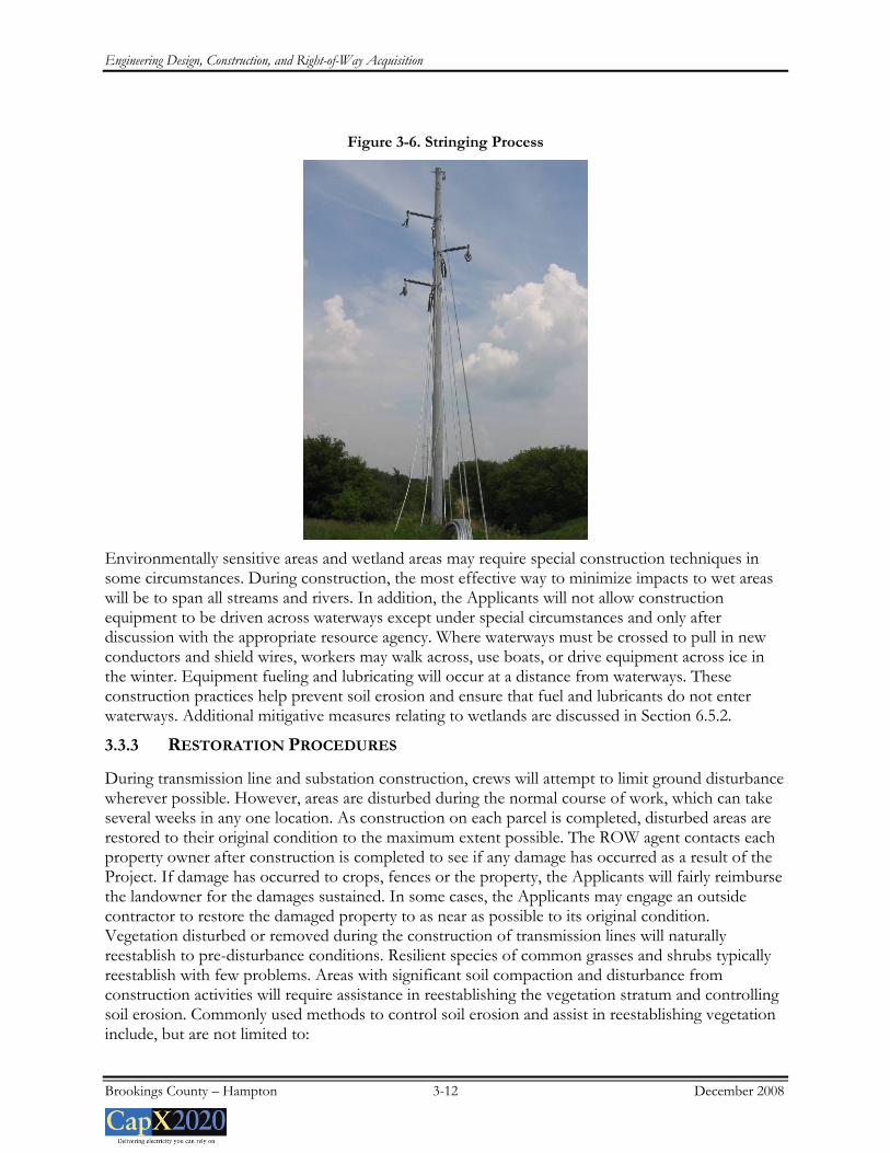
The conductors are then installed by establishing stringing setup areas within the ROW or on temporary construction easements outside the ROW. These stringing setup areas are usually located every two miles along a project route. Conductor stringing operations also require brief access to each structure to secure the conductor wire to the insulator hardware and the shield wire to clamps once final sag is established. When the transmission line crosses streets, roads, highways, or other energized conductors or obstructions, a temporary guard or clearance poles may be installed. This ensures that conductors will not obstruct traffic or contact existing energized conductors or other cables during stringing operations; it also protects the conductors from damage. Figure 3-6 shows a single circuit steel 115 kV structure midway through the stringing process.
Engineering Design, Construction, and Right-of-Way Acquisition
Brookings County – Hampton 3-12 December 2008
Figure 3-6. Stringing Process
Environmentally sensitive areas and wetland areas may require special construction techniques in some circumstances. During construction, the most effective way to minimize impacts to wet areas will be to span all streams and rivers. In addition, the Applicants will not allow construction equipment to be driven across waterways except under special circumstances and only after discussion with the appropriate resource agency. Where waterways must be crossed to pull in new conductors and shield wires, workers may walk across, use boats, or drive equipment across ice in the winter. Equipment fueling and lubricating will occur at a distance from waterways. These construction practices help prevent soil erosion and ensure that fuel and lubricants do not enter waterways. Additional mitigative measures relating to wetlands are discussed in Section 6.5.2.
3.3.3 RESTORATION PROCEDURES
During transmission line and substation construction, crews will attempt to limit ground disturbance wherever possible. However, areas are disturbed during the normal course of work, which can take several weeks in any one location. As construction on each parcel is completed, disturbed areas are restored to their original condition to the maximum extent possible. The ROW agent contacts each property owner after construction is completed to see if any damage has occurred as a result of the Project. If damage has occurred to crops, fences or the property, the Applicants will fairly reimburse the landowner for the damages sustained. In some cases, the Applicants may engage an outside contractor to restore the damaged property to as near as possible to its original condition. Vegetation disturbed or removed during the construction of transmission lines will naturally reestablish to pre-disturbance conditions. Resilient species of common grasses and shrubs typically reestablish with few problems. Areas with significant soil compaction and disturbance from construction activities will require assistance in reestablishing the vegetation stratum and controlling soil erosion. Commonly used methods to control soil erosion and assist in reestablishing vegetation include, but are not limited to:
Engineering Design, Construction, and Right-of-Way Acquisition
Brookings County – Hampton 3-13 December 2008
• Erosion control blankets with embedded seeds
• Silt fences
• Hay bales
3.3.4 MAINTENANCE PROCEDURES
Transmission lines and substations are designed to operate for decades and require only moderate maintenance, particularly in the first few years of operation.
The estimated service life of a transmission line for accounting purposes is approximately 40 years. However, practically speaking, HVTLs are seldom completely retired. Transmission infrastructure has very few mechanical elements and is built to withstand normal weather extremes. With the exception of severe weather, such as tornadoes and heavy ice storms, transmission lines rarely fail. They are automatically taken out of service by the operation of protective relaying equipment when a fault is sensed on the system; such interruptions are usually only momentary. Scheduled maintenance outages are also infrequent. As a result, the average annual availability of transmission infrastructure is very high, in excess of 99 percent.
The primary operating and maintenance cost for transmission facilities is the cost of inspections, usually done monthly by air. Annual operating and maintenance costs for transmission lines in Minnesota and the surrounding states vary. For voltages from 115 kV through 345 kV, past experience has shown that costs are approximately $300 to $500 per mile. Actual transmission line-specific maintenance costs depend on the setting, the amount of vegetation management necessary, storm damage occurrences, structure types, materials used and the age of the transmission line.
Substations require a certain amount of maintenance to keep them functioning in accordance with accepted operating parameters and NESC and NERC requirements. Transformers, circuit breakers, batteries, protective relays and other equipment need to be serviced periodically in accordance with the manufacturer’s recommendation. The site itself must be kept free of vegetation and drainage must be maintained.
The substation equipment that will be installed as part of the Project includes state of the art circuit breakers designed to minimize the risk of sulfur hexafluoride (“SF6”) release. SF6, used as an insulator in breakers, is considered a greenhouse gas by the Environmental Protection Agency (“EPA”). Current technologies require less SF6 at lower pressures than older technologies, resulting in a more secure system. Absent an equipment failure, newer breakers contain and maintain SF6 levels and do not sustain the releases associated with older circuit breakers.
3.4 ELECTRIC AND MAGNETIC FIELDS
The term electromagnetic fields (“EMF”) refers to electric and magnetic fields that are coupled together such as in high frequency radiating fields. For the lower frequencies associated with power lines, EMF should be separated into electric and magnetic fields, which arise from the flow of electricity and the voltage of a power line. Electric fields are measured in kilovolts per meter (“kV/m”) and magnetic fields are measured in milliGauss (“mG”). The intensity of the electric field is proportional to the voltage of the transmission line, while the intensity of the magnetic field is proportional to the current flow through the conductors. Transmission lines operate at a power frequency of 60 hertz (cycles per second).
There is no federal standard for transmission line electric fields. The Commission, however, has imposed a maximum electric field limit of 8 kV/meter measured at one meter above the ground. See
Engineering Design, Construction, and Right-of-Way Acquisition
Brookings County – Hampton 3-14 December 2008
In the Matter of the Petitions of Northern States Power Company d/b/a Xcel Energy and Dairyland Cooperative for Permits to Construct a 115 kV and 161 kV Transmission Line from Taylors Falls to Chisago County Substation, Docket No. E-002/TL-06-1677, Environmental Assessment, at p. 45 (Aug. 20, 2007). The standard was designed to prevent serious hazards from shocks when touching large objects parked under alternating current (“AC”) transmission lines of 500 kV or greater. The maximum electric field associated with the Applicant’s proposal, measured at one meter above ground, is calculated to be 3.73 kV/m.
Considerable research has been conducted over the past three decades to determine if exposure to power-frequency (60 hertz) magnetic fields causes biological responses and health effects. Epidemiological and toxicological studies have shown no statistically significant association or weak associations between EMF exposure and health risks. The possible impact of EMF exposure to human health has also been investigated by public health professionals for the past several decades. While the general consensus is that electric fields pose no human risk, the question of whether exposure to magnetic fields can cause biological responses or health effects continues to be debated.
In 1999, the National Institute of Environmental Health Sciences (“NIEHS”) issued its final report on “Health Effects from Exposure to Power-Line Frequency Electric and Magnetic Fields” in response to the Energy Policy Act of 1992. NIEHS concluded that the scientific evidence linking EMF exposures with health risks is weak, a finding that does not warrant aggressive regulatory concern. However, because of the weak scientific evidence that supports some association between EMF and health effects and the common exposure to electricity in the United States, passive regulatory action, such as providing public education on reducing exposures, is warranted.
In 2007, the World Health Organization (“WHO”) concluded a review of the health implications of electromagnetic fields. In this report, the WHO stated:
Uncertainties in the hazard assessment [of epidemiological studies] include the role that control selection bias and exposure misclassification might have on the observed relationship between magnetic fields and childhood leukemia. In addition, virtually all of the laboratory evidence and the mechanistic evidence fail to support a relationship between low-level ELF [Extremely Low Frequency] magnetic fields and changes in biological function or disease status. Thus, on balance, the evidence is not strong enough to be considered causal, but sufficiently strong to remain a concern. (Environmental Health Criteria Volume N°238 on Extremely Low Frequency Fields at p. 12, WHO (2007)).
In addition, regarding disease outcomes, aside from childhood leukemia, the WHO stated that:
A number of other diseases have been investigated for possible association with ELF magnetic field exposure. These include cancers in both children and adults, depression, suicide, reproductive dysfunction, developmental disorders, immunological modifications and neurological disease. The scientific evidence supporting a linkage between ELF magnetic fields and any of these diseases is much weaker than for childhood leukemia and in some cases (for example, for cardiovascular disease or breast cancer) the evidence is sufficient to give confidence that magnetic fields do not cause the disease. (Id. at p.12).
Engineering Design, Construction, and Right-of-Way Acquisition
Brookings County – Hampton 3-15 December 2008
Furthermore, in their “Summary and Recommendations for Further Study” WHO emphasized that:
the limit values in [EMF] exposure guidelines [not] be reduced to some arbitrary level in the name of precaution. Such practice undermines the scientific foundation on which the limits are based and is likely to be an expensive and not necessarily effective way of providing protection. (Id. at p. 12).
WHO concluded that:
given both the weakness of the evidence for a link between exposure to ELF magnetic fields and childhood leukemia, and the limited impact on public health if there is a link, the benefits of exposure reduction on health are unclear. Thus, the costs of precautionary measures should be very low. (Id. At p. 13).
Wisconsin, Minnesota and California have all conducted literature reviews or research to examine this issue. In 2002, Minnesota formed an Interagency Working Group (Working Group) to evaluate the body of research and develop policy recommendations to protect the public health from any potential problems resulting from HVTL EMF effects. The Working Group consisted of staff from various state agencies. Its findings were published in a White Paper on Electric and Magnetic Field (EMF) Policy and Mitigation Options in September 2002 (Minnesota Department of Health, 2002). The report summarized the findings of the Working Group as follows:
Research on the health effects of EMF has been carried out since the 1970s. Epidemiological studies have mixed results – some have shown no statistically significant association between exposure to EMF and health effects, some have shown a weak association. More recently, laboratory studies have failed to show such an association, or to establish a biological mechanism for how magnetic fields may cause cancer. A number of scientific panels convened by national and international health agencies and the United States Congress have reviewed the research carried out to date. Most researchers concluded that there is insufficient evidence to prove an association between EMF and health effects; however, many of them also concluded that there is insufficient evidence to prove that EMF exposure is safe. (Id. at p. 1.)
Based on the Working Group and WHO findings, the Commission has repeatedly found that “there is insufficient evidence to demonstrate a causal relationship between EMF exposure and any adverse human health effects.” (In the Matter of the Application of Xcel Energy for a Route Permit for the Lake Yankton to Marshall Transmission Line Project in Lyon County, Docket No. E-002/TL-07-1407, Findings of Fact, Conclusions of Law and Order Issuing a Route Permit to Xcel Energy for the Lake Yankton to Marshall Transmission Project at p. 7-8 (Aug. 29, 2008); See also, In the Matter of the Application for a HVTL Route Permit for the Tower Transmission Line Project, Docket No. ET-2, ET015/TL-06-1624, Findings of Fact, Conclusions of Law and Order Issuing a Route Permit to Minnesota Power and Great River Energy for the Tower Transmission Line Project and Associated Facilities at p. 23 (Aug. 1, 2007)).
Engineering Design, Construction, and Right-of-Way Acquisition
Brookings County – Hampton 3-16 December 2008
The OES has also analyzed the potential impacts of EMF on human health and safety and concluded that there is insufficient evidence to show a link between EMF and health effects:
A number of national and international health agencies (The Minnesota Department of Health, The World Health Organization, The National Institute of Environmental Health Sciences) have generally concluded in their research that there is insufficient evidence to prove a connection between EMF exposure and health effects. Research has not been able to establish a cause and effect relationship between exposure to magnetic fields and human disease, nor a plausible biological mechanism by which exposure to EMF could cause disease.
In the Matter of the Application for a Route Permit for the Yankee Substation to Brookings County Substation 115 kV High Voltage Transmission Line Project, Docket No. E002/TL-07-1626, Environmental Assessment p. 10 (May 30, 2008).
The Public Service Commission of Wisconsin (“PSCW”) has periodically reviewed the science on EMF since 1989 and has held hearings to consider the topic of EMF and human health effects. The most recent hearings on EMF were held in July 1998. In January 2008, the PSCW published a fact sheet regarding EMF, which noted:
Many scientists believe the potential for health risks for exposure to EMF is very small. This is supported, in part, by weak epidemiological evidence and the lack of a plausible biological mechanism that explains how exposure to EMF could cause disease. The magnetic fields produced by electricity are weak and do not have enough energy to break chemical bonds or to cause mutations in DNA. Without a mechanism, scientists have no idea what kind of exposure, if any, might be harmful. In addition, whole animal studies investigating long-term exposure to power frequency EMF have shown no connection between exposure and cancer of any kind (EMF-Electric & Magnetic Fields, Public Service Commission of Wisconsin (January 2008)).
There are presently no Minnesota regulations pertaining to EMF exposure. Applicants provide information to the public, interested customers, and employees so they can make informed decisions about EMF. Such information includes EMF measurements for customers and employees upon their request.
3.4.1 ELECTRIC FIELDS
The electric field from a transmission line can couple with a conductive object, such as a vehicle or a metal fence, which is in close proximity to the transmission line. This will induce a voltage on the object, which is dependent on many factors, including the weather; object shape, size, orientation, and capacitance; object to ground resistance; and location along the ROW. If these objects are insulated or semi-insulated from the ground and a person touches them, a small current will pass through the person’s body to the ground. This might be accompanied by a spark discharge and mild shock, similar to what can occur when a person walks across a carpet and touches a grounded object or another person.
Engineering Design, Construction, and Right-of-Way Acquisition
Brookings County – Hampton 3-17 December 2008
The main concern with induced voltage on an object is the current flow through the person to ground if a person were to touch the object. The best method to avoid these discharges is not to park equipment directly under the transmission line. Another option would be to drop a chain that is attached to the equipment onto the ground (or lower the head to the ground on a combine) prior to dismounting if parked near a transmission line and pulling the chain (or head) up after getting into the equipment. It is important to note that use of a chain attached to farm machinery to eliminate spark discharges is not necessary for safety reasons and therefore should only be considered if the discharge is considered annoying to the operator and the vehicle must be parked under the transmission line.
To ensure that any discharge does not reach unsafe levels, the NESC requires that any discharge be less than 5 milliamperes (“ma”). Based on the Applicants’ 115 kV, 230 kV, and 345 kV transmission line operating experience, the discharge from any large mobile object—such as a bus, truck, or farm machinery— parked under or adjacent to the transmission line will unlikely reach levels considered an annoyance and are less than the 5 ma NESC limit. The Applicants will also assure that any fixed object, such as a fence or other large permanent conductive object in close proximity to or parallel to the transmission line, will be grounded so any discharge would be less than the 5 ma NESC limit.
Similarly, the Commission’s standard of maximum electric field limit of 8 kV/m measured one meter above ground was designed to prevent serious hazard from shocks when touching large objects placed under AC transmission lines of 500 kV or greater. The proposed facilities will comply with the NESC and Commission standards.
Table 3-3 provides electric fields at maximum conductor voltage for each type of the transmission line facilities proposed. The nominal voltages are 69 kV, 115 kV, 230 kV, and 345 kV. Electric fields were calculated using ENVIRO, a software program licensed by the Electric Power Research Institute, Inc. (“EPRI”). The calculated electric field assumed the maximum operating voltage (72 kV, 121 kV, 242 kV, 362 kV), which is 105 percent of the nominal voltage for all the transmission lines. For any specific design, the set of phase conductors height above ground has a marked influence on the maximum electric field. The phasing arrangement is of particular importance for the maximum field for a double circuit configuration (two circuits on a single structure).
Engineering Design, Construction, and Right-of-Way Acquisition
Brookings County – Hampton 3-18 December 2008
Table 3-3. Calculated Electric Fields (kV/m) for Proposed Single/Double/Triple Circuit
Transmission Line Designs (3.28 Feet above ground)
Other potential impacts of electric fields include interference with the operation of pacemakers and implantable cardioverters/defibrillators. Interference with implanted cardiac devices can occur if the electric field intensity is high enough to induce sufficient body currents to cause interaction.
Modern bipolar devices are much less susceptible to interactions with electric fields. Medtronic and Guidant, manufacturers of pacemakers and implantable cardioverters/defibrillators, have indicated that electric fields below 6 kV/meter are unlikely to cause interactions affecting operation of most of their devices.
Older unipolar designs are more susceptible to electric field interference. Research completed by Toivoen et al. (1991) indicated that the earliest evidence of interference was in electric fields ranging from 1.2 to 1.7 kV/meter. For older style unipolar designs, the electric field for some proposed structure types does exceed levels that Toivoen et al. has indicated may produce interference. However, a recent paper (Scholten et al., 2005) concludes that the risk of interference inhibition of
Engineering Design, Construction, and Right-of-Way Acquisition
Brookings County – Hampton 3-19 December 2008
unipolar cardiac pacemakers from high voltage power lines in everyday life is small. In the unlikely event a pacemaker is impacted, the effect is typically a temporary asynchronous pacing (commonly referred to as reversion mode or fixed rate pacing). The pacemaker returns to its normal operation when the person moves away from the source of the interference.
3.4.2 MAGNETIC FIELDS
Table 3-4 provides calculated magnetic fields for each structure and conductor configuration proposed for the Project. Magnetic fields were calculated for each section of the Project and under two system conditions: current flow at the conductor’s thermal capacity and average flow. Current is given in amps. A conductor’s design thermal capacity is the expected peak current flow. The peak current flow is the expected summer peak current in year 2010 under normal system intact conditions. The peak magnetic field values are calculated at a point directly under the transmission line and where the conductor is closest to the ground. The same method is used to calculate the magnetic field at varying distances from the centerline of the structure. The magnetic field profile data show that magnetic field levels decrease rapidly (inverse square of the distance from source) from the centerline.
Because the magnetic field produced by the transmission line is dependent on the current flowing on its conductors, the actual magnetic field when the Project is in service is typically less than that shown in the table. This is because the graphs represent the magnetic field with current flow at the conductor’s thermal limit and at expected normal peak current flow. Actual current flow on the transmission line will vary as magnetic field changes throughout the day and will be less than peak levels during most hours of the year.
As load growth occurs, the current flow on the line will increase, and because the magnetic field is directly related to current flow, the magnetic field will also increase. The graphs depicting the magnetic field at the conductor’s thermal limits represent the maximum expected magnetic field because the current flow is at the conductor’s capacity.
Engineering Design, Construction and Right-of-Way Acquisition
Brookings County – Hampton 3-20 December 2008
Table 3-4. Calculated Magnetic Fields (milligauss) for Proposed Single/Double/Triple Circuit Transmission Line Designs (3.28 feet above ground)
Peak 826.7 0.60 1.81 10.40 19.02 37.45 94.04 37.90 19.33 10.61 1.86 0.61 Single Pole Davit Arm 345 kV/345 kV Double Circuit with both Circuits In Service
Peak 826.7 2.23 4.65 13.88 20.14 30.96 80.21 56.92 34.74 22.25 6.16 2.70 Single Pole Davit Arm 345 kV/345 kV Double Circuit with one Circuit In Service
Brookings to Lyon County. Average 496.02 1.34 2.79 8.33 12.09 18.58 48.13 34.15 20.85 13.35 3.69 1.62
Peak 644.3 0.47 1.41 8.10 14.83 29.19 73.29 29.54 15.07 8.27 1.45 0.47 Single Pole Davit Arm 345 kV/345 kV Double Circuit with both Circuits In Service
Lyon County to Hazel Creek Average 386.58 0.28 0.85 4.86 8.90 17.51 43.97 17.72 9.04 4.96 0.87 0.28
Peak 644.3 1.74 3.62 10.82 15.70 24.13 62.52 44.36 27.08 17.34 4.80 2.10Single Pole Davit Arm 345 kV/345 kV Double Circuit with one Circuit In Service
Davit Arm 345 kV/345 kV Double Circuit with one Circuit In Service
Creek to Minnesota Valley Average 148.44 0.40 0.83 2.49 3.62 5.56 14.40 10.22 6.24 4.00 1.11 0.48
Peak 1005.9 0.73 2.2 12.65 23.15 45.57 114.42 46.12 23.53 12.91 2.26 0.74 Single Pole Davit Arm 345 kV/345 kV Double Circuit with both Circuits In Service
Peak 1005.9 2.71 5.66 16.89 24.51 37.68 97.60 69.26 42.28 27.07 7.49 3.28Single Pole Davit Arm 345 kV/345 kV Double Circuit with one Circuit In Service
Helena to Lake Marion Average 603.54 1.63 3.39 10.13 14.71 22.61 58.56 41.56 25.37 16.24 4.49 1.97
Peak 354.8 0.26 0.78 4.46 8.16 16.07 40.36 16.27 8.30 4.55 0.80 0.26 Single Pole Davit Arm 345 kV/345 kV Double Circuit with both Circuits In Service
Engineering Design, Construction and Right-of-Way Acquisition
Brookings County – Hampton 3-23 December 2008
3.4.3 STRAY VOLTAGE
3.4.3.1 Definition
“Stray voltage” is a condition that can occur on the electric service entrances to structures from distribution lines—not transmission lines. More precisely, stray voltage exists between the neutral wire of the service entrance and grounded objects in buildings such as barns and milking parlors.
Transmission lines do not, by themselves, create stray voltage because they do not connect to businesses or residences. However, transmission lines can induce stray voltage on a distribution circuit that is parallel to and immediately under the transmission line. Appropriate measures will be taken to prevent stray voltage problems when the transmission lines proposed in this Application parallel or cross distribution lines.
3.4.3.2 Farming Operations, Vehicle Use, and Metal Buildings Near Power Lines
Insulated electric fences used in livestock operations can pick up an induced charge from transmission lines. Usually, the induced charge will drain off when the charger unit is connected to the fence. When the charger is disconnected, either for maintenance or when the fence is being built, shocks may result. Potential shocks can be prevented by using two methods: i) one or more of the fence insulators can be shorted out to ground with a wire when the charger is disconnected; or, ii) an electric filter can be installed that grounds out charges induced from a power line while still allowing the charger to be effective.
Farm equipment, passenger vehicles, and trucks may be safely used under and near power lines. The power lines will be designed to meet or exceed minimum clearance requirements over roads, driveways, cultivated fields, and grazing lands specified by the NESC. Recommended clearances within the NESC are designed to accommodate a relative vehicle height of 14 feet.
There is a potential for vehicles under HVTLs to build up an electric charge. If this occurs, the vehicle can be grounded by attaching a grounding strap long enough to touch the earth. However, such buildup is a rare event because vehicles generally are effectively grounded through tires. Modern tires provide an electrical path to the ground because carbon black, a good electricity conductor, is added when they are produced. Metal parts of farming equipment are frequently in contact with the ground when plowing or engaging in various other activities. Therefore, vehicles will not normally build up charge unless they have unusually old tires or are parked on dry rock, plastic or other surfaces that insulate them from the ground.
Another issue that arises when operating vehicles near power lines is whether vehicles can be safely refueled. The possibility of fuel ignition under a power line is remote. Nevertheless, the Applicants do not recommend refueling vehicles directly under or within 100 feet of a transmission line 200 kV or greater.
Buildings are permitted near transmission lines, but are generally prohibited within the ROW itself because a structure under a transmission line may interfere with safe operation. For example, a fire in a building located in the ROW could damage a transmission line. As a result, NESC guidelines establish clear zones for transmission facilities. Metal buildings may have unique issues. For example, metal buildings near transmission lines of 200 kV or greater must be properly grounded. People who have questions about a new or existing metal structure can contact the Applicants for further information about proper grounding requirements.
Engineering Design, Construction and Right-of-Way Acquisition
Brookings County – Hampton 3-24 December 2008
3.5 TRANSMISSION LINE RELIABILITY
When developing route segments for the Project, the Applicants analyzed the potential to collocate portions of the transmission line on the same structures as existing electric facilities as well as routing the 345 kV line parallel to existing facilities. The Applicants concluded that except in the case of certain Minnesota River crossings, collocating the new facilities with existing facilities on common structures was not feasible because of reliability concerns. Numerous paralleling opportunities were identified, however, and where appropriate, incorporated into the proposed routes.
When identifying suitable routes for new single circuit transmission lines, planning engineers typically analyze whether the new transmission line can be collocated with another existing transmission line (also referred to as double-circuited). In evaluating the appropriateness of such multiple circuit structures, the Applicants applied reliability criteria established by the NERC. NERC defines minimum transmission system performance requirements that must be met for different system conditions. They define different types of system events and group them into four different categories:
Category A – All facilities in service (no contingencies)
Category B – Event resulting in loss of a single element
Category C – Event(s) resulting in the loss of two or more (multiple) elements.
Category D – Extreme event resulting in two or more (multiple) elements removed or cascading out of service
For each of the different categories of contingencies, each reliability region is allowed to expand on the NERC requirements to make them more stringent. This 345 kV transmission line Project is in the Midwest Reliability Organization (“MRO”) reliability region. NERC Category C (contingency C5) includes the loss of “any two circuits of a multiple circuit towerline” with an exclusion for multiple circuit towers used over short distances in accordance with regional exemption criteria. In the MRO region, if the transmission line is operated at a voltage of 100 kV or higher and if the overall distance that transmission lines are double circuited is greater than one mile, then it falls under the NERC Category C contingency definition.
NERC reliability standards require utilities to plan a transmission system to be able to survive all Category C contingencies without system performance violations. Double circuit construction has been found to be acceptable if the power system can reliably withstand simultaneous failure of both circuits on a common structure. Double circuit construction could be appropriate in some situations where the two circuits serve different functions, connect different substations, split away and proceed in different directions, or where high capacity (but not redundancy) is required.
Common tower outages for double circuit transmission lines could be caused by:
• electrical failure of transmission line insulation due to lightning strike • mechanical failure of one or more structures • broken shield wire falling into power conductors • wind-blown debris causing conductor-conductor short circuits • insulator contamination due to road salt, soot or agricultural chemicals • wind, sleet and ice conditions • contact with aircraft or construction equipment (crane, dump truck)
Engineering Design, Construction and Right-of-Way Acquisition
Brookings County – Hampton 3-25 December 2008
• protective relaying malfunction (“sympathetic tripping” due to fault on adjacent circuit) These common tower failure mechanisms have all occurred on the transmission system within the northern MRO transmission system on double circuit transmission lines.
Double circuiting of transmission lines is employed, for example, in situations where two circuits serve different functions or where high capacity (but not redundancy) is required. Double circuiting is not acceptable in situations where failure of both circuits would jeopardize reliability because of the substantial risk that both transmission lines will be out of service simultaneously. For example, if storm damage caused a double circuit structure to fail, it can be expected that an outage would occur on both circuits. Thus, if under the relevant reliability rules it were determined that simultaneous outage would jeopardize service, double circuiting would not be allowed.
This Project is proposed to be constructed with double circuit structures – approximately half will be strung as double circuit upon installation; the other half will be strung with a single circuit initially and a second circuit will be added at a later date. Accordingly, there are no opportunities to double circuit the transmission line with existing transmission facilities.
Some stakeholders have inquired about whether the new 345 kV segments could be “triple circuited” with an existing transmission line. In addition to the reliability consideration outlined above, triple circuit structures pose additional maintenance safety issues. Operating a bucket truck on a de-energized line and performing inspection and maintenance duties increases the chances of incidental contact with the adjacent energized line. Depending on the physical circumstances, it may be necessary to de-energize all three lines when performing maintenance on one of the lines. The de-energization of all circuits would require analysis to ensure adequate system reliability. In addition, if all lines are not de-energized, the energized line(s) could induce stray voltage on the de-energized line(s), which would require additional grounding measures for appropriate personnel safety.
Because of these reliability and safety concerns, utilities avoid triple circuit construction wherever reasonably possible. Such configurations are typically limited to short distances where triple circuit construction is necessary to minimize environmental impacts—to consolidate facilities at river crossings, for example. For this Project, the Applicants are proposing triple circuit construction in two Minnesota River crossing locations. The first crossing (Redwood crossing) is proposed to be triple circuited with an existing 115 kV transmission line. The second crossing (West Belle Plaine crossing) is proposed to be triple circuited with an existing 69 kV transmission line. In both cases, triple circuiting is proposed to consolidate facilities, minimizing the amount of vegetation removed because of the Project. Aesthetic impacts are therefore minimized at the river crossings.
Planning engineers analyzed the potential impact of a triple circuit configuration in these areas. In many cases, triple circuiting requires upgrades on the surrounding transmission system to reliably sustain the loss of two circuits. However, the triple circuit analysis for the two proposed river crossings showed that the system could withstand an outage of any two of the circuits as required by NERC criteria.
The river crossing segments will be designed to minimize outage risks and to reduce maintenance requirements. This is accomplished by using special structures and attaching components designed and constructed on either side of long spans across the rivers. These special structures are usually larger than typical structures to allow for wider conductor spacing, which helps reduce outages. The components used to connect the conductors to the structures are specified to handle the higher stresses involved with longer spans.
Engineering Design, Construction and Right-of-Way Acquisition