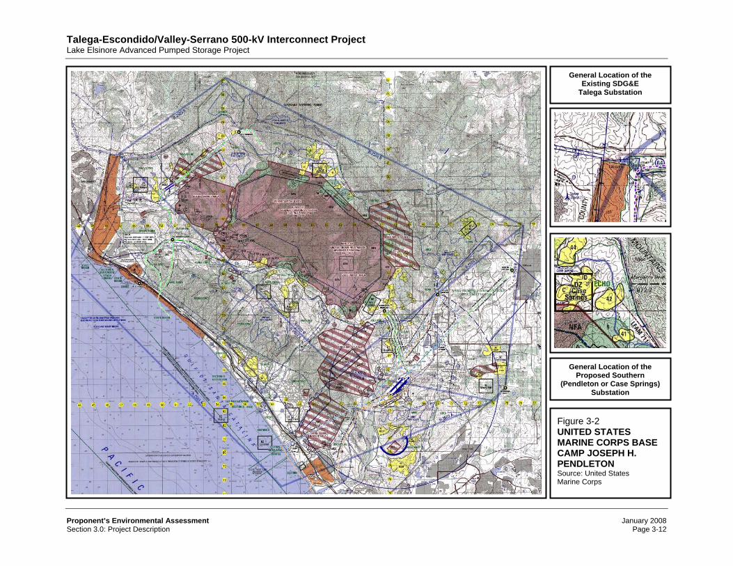
Talega-Escondido/Valley-Serrano 500-kV Interconnect Project Lake Elsinore Advanced Pumped Storage Project Proponents Environmental Assessment January 2008 Section 3.0: Project Description Page 3-1 3.0 PROJECT DESCRIPTION 3.1 Location and Vicinity With the exception of remote system upgrades, as identified in the interconnection facilities studies performed by SCE and SDG&E 1 and more thoroughly described herein, the TE/VS Interconnect project’s general location is depicted in Figure 3-1 (Regional Vicinity Map) and includes those portions of Riverside, San Diego, and Orange Counties in which the proposed transmission alignment and other project-related facilities are located. The area illustrated also encompasses SCE’s existing Valley-Serrano 500-kV transmission line and SDG&E’s existing 230-kV Talega-Escondido transmission line since those systems would be interconnected as a result of the construction and operation of the TE/VS Interconnect project. As shown, the TE/VS Interconnect project area generally extend from north and west of the City of Lake Elsinore (Riverside County) southward to north and west of the City of Oceanside (San Diego County) westward toward the San Onofre Nuclear Generating Station (SONGS) (San Diego County), and eastward to City of Escondido (San Diego County). Excluding certain system upgrades that have been identified in the interconnection facilities studies conducted by SCE and SDG&E, 2 all proposed project-related facilities and improvements are located in the Counties of Riverside and San Diego. Excluding SDG&E’s existing 230-kV Talega-Escondido transmission line, SDG&E’s existing Talega and Escondido substations, and SCE’s existing Valley and Serrano substations, the TE/VS Interconnect project is located within the United States Geological Survey’s (USGS) 7.5-Minute Alberhill, Lake Elsinore, Wildomar, Fallbrook, and Margarita Peak topographic quadrangles. SDG&E’s Talega-Escondido 230-kV transmission line is mostly located in northern San Diego County. The transmission line terminates south of the County of Orange at its western terminus at the existing Talega substation and extends into Riverside County for short segments west of Camp Pendleton. As illustrated in Figure 3-2 (United States Marine Corps Base – Camp Joseph H. Pendleton), the western portions of SDG&E’s existing 230-kV transmission line is located within an existing military reservation (Camp Pendleton). When the CPUC-permitted TE/VS Interconnect project is considered in combination with the FERC-licensed LEAPS project, many of the combined projects’ major elements are located in southwestern Riverside County, near Lake Elsinore. Lake Elsinore lies approximately 60 miles southeast of Los Angeles and about 22 miles southwest of the City of Riverside. Lake Elsinore is located within the corporate boundaries of the City of Lake Elsinore (City) and is a natural low point of the San Jacinto River and its drainage basin. Over 90 percent of that watershed drains first into Railroad Canyon Reservoir (Canyon Lake) and then flows into Lake Elsinore. Portions of the proposed TE/VS Interconnect and LEAPS projects are or may be located on lands owned, controlled, and/or maintained by SCE and SDG&E within the City of Lake Elsinore and the Counties of Orange, Riverside, San Diego, and San Bernardino. In addition, portions of 1 / Southern California Edison Company, Nevada Hydro Company, Inc. and Elsinore Valley Municipal Water District Lake Elsinore Advanced Pumped Storage Project, Southern California Edison Company Facilities Study, November 30, 2006; San Diego Gas & Electric Company, Lake Elsinore Advanced Pumped Storage Project, Interconnection Facilities Study, Draft Report, December 15, 2006. 2 / Southern California Edison Company, Nevada Hydro Company, Inc. and Elsinore Valley Municipal Water District Lake Elsinore Advanced Pumped Storage Project, Southern California Edison Company Facilities Study, November 30, 200 San Diego Gas & Electric Company, Lake Elsinore Advanced Pumped Storage Project, Interconnection Facilities Study, Draft Report, December 15, 2006.
Transcript
Talega-Escondido/Valley-Serrano 500-kV Interconnect Project Lake Elsinore Advanced Pumped Storage Project
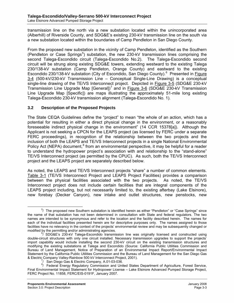
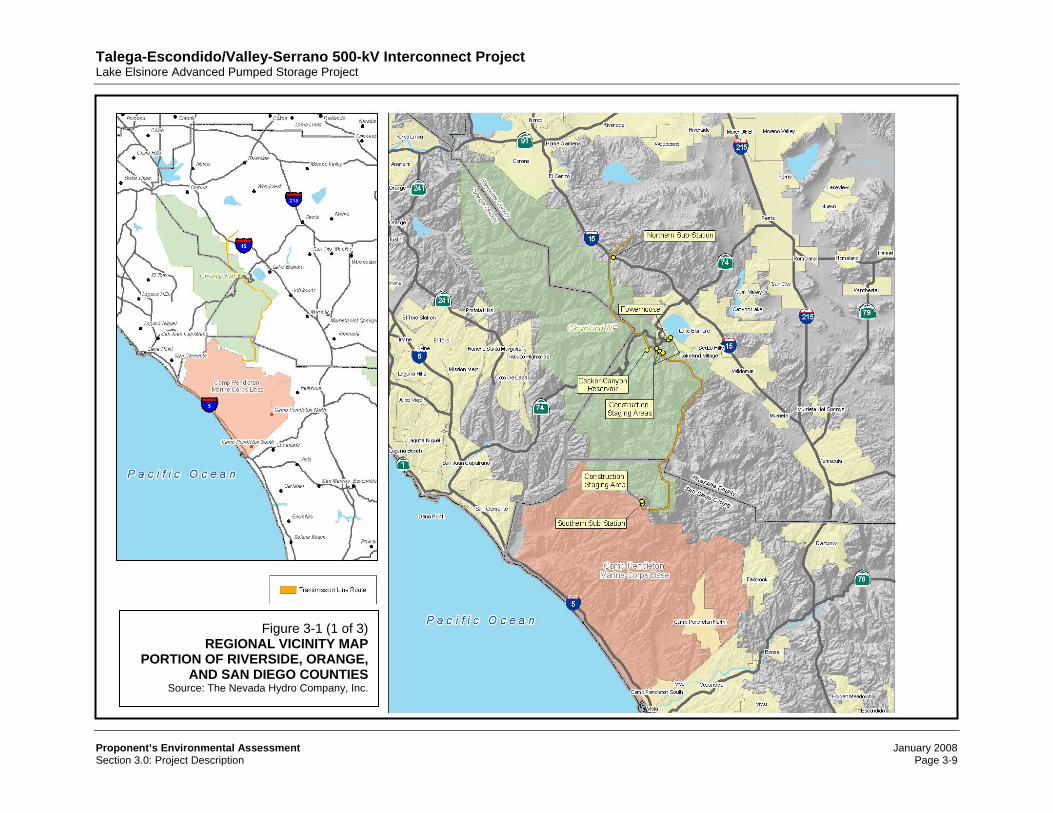
3.0 PROJECT DESCRIPTION 3.1 Location and Vicinity With the exception of remote system upgrades, as identified in the interconnection facilities studies performed by SCE and SDG&E1 and more thoroughly described herein, the TE/VS Interconnect project’s general location is depicted in Figure 3-1 (Regional Vicinity Map) and includes those portions of Riverside, San Diego, and Orange Counties in which the proposed transmission alignment and other project-related facilities are located. The area illustrated also encompasses SCE’s existing Valley-Serrano 500-kV transmission line and SDG&E’s existing 230-kV Talega-Escondido transmission line since those systems would be interconnected as a result of the construction and operation of the TE/VS Interconnect project. As shown, the TE/VS Interconnect project area generally extend from north and west of the City of Lake Elsinore (Riverside County) southward to north and west of the City of Oceanside (San Diego County) westward toward the San Onofre Nuclear Generating Station (SONGS) (San Diego County), and eastward to City of Escondido (San Diego County). Excluding certain system upgrades that have been identified in the interconnection facilities studies conducted by SCE and SDG&E,2 all proposed project-related facilities and improvements are located in the Counties of Riverside and San Diego. Excluding SDG&E’s existing 230-kV Talega-Escondido transmission line, SDG&E’s existing Talega and Escondido substations, and SCE’s existing Valley and Serrano substations, the TE/VS Interconnect project is located within the United States Geological Survey’s (USGS) 7.5-Minute Alberhill, Lake Elsinore, Wildomar, Fallbrook, and Margarita Peak topographic quadrangles. SDG&E’s Talega-Escondido 230-kV transmission line is mostly located in northern San Diego County. The transmission line terminates south of the County of Orange at its western terminus at the existing Talega substation and extends into Riverside County for short segments west of Camp Pendleton. As illustrated in Figure 3-2 (United States Marine Corps Base – Camp Joseph H. Pendleton), the western portions of SDG&E’s existing 230-kV transmission line is located within an existing military reservation (Camp Pendleton). When the CPUC-permitted TE/VS Interconnect project is considered in combination with the FERC-licensed LEAPS project, many of the combined projects’ major elements are located in southwestern Riverside County, near Lake Elsinore. Lake Elsinore lies approximately 60 miles southeast of Los Angeles and about 22 miles southwest of the City of Riverside. Lake Elsinore is located within the corporate boundaries of the City of Lake Elsinore (City) and is a natural low point of the San Jacinto River and its drainage basin. Over 90 percent of that watershed drains first into Railroad Canyon Reservoir (Canyon Lake) and then flows into Lake Elsinore. Portions of the proposed TE/VS Interconnect and LEAPS projects are or may be located on lands owned, controlled, and/or maintained by SCE and SDG&E within the City of Lake Elsinore and the Counties of Orange, Riverside, San Diego, and San Bernardino. In addition, portions of
1/ Southern California Edison Company, Nevada Hydro Company, Inc. and Elsinore Valley Municipal Water
District Lake Elsinore Advanced Pumped Storage Project, Southern California Edison Company Facilities Study, November 30, 2006; San Diego Gas & Electric Company, Lake Elsinore Advanced Pumped Storage Project, Interconnection Facilities Study, Draft Report, December 15, 2006.
2/ Southern California Edison Company, Nevada Hydro Company, Inc. and Elsinore Valley Municipal Water District Lake Elsinore Advanced Pumped Storage Project, Southern California Edison Company Facilities Study, November 30, 200 San Diego Gas & Electric Company, Lake Elsinore Advanced Pumped Storage Project, Interconnection Facilities Study, Draft Report, December 15, 2006.
Talega-Escondido/Valley-Serrano 500-kV Interconnect Project Lake Elsinore Advanced Pumped Storage Project
the proposed projects are or may be located upon, within, and/or beneath public and privately owned lands located in unincorporated portions of southwestern Riverside County, northeast Orange County, and northwestern San Diego County and within the corporate boundaries of the City of Lake Elsinore. Public lands upon which the projects’ facilities are proposed include or may include properties under the ownership or control of the following governmental entities. City of Lake Elsinore, including lands located within the ordinary high-water mark
(OHWM) of the inland water body known as Lake Elsinore (Lake Elsinore); Counties of Orange, Riverside, and San Diego; Western Riverside County Regional Conservation Agency (RCHCA), Metropolitan Water
District of Southern California (MWD), and California Department of Fish and Game (CDFG), including lands located within the Lake Mathews-Estelle Mountain Reserve;
California Department of Transportation (Caltrans), including lands within the rights-of-way for the Interstate 15 (Corona) Freeway and State Route 74 (Ortega Highway);
National Forest System (NFS) lands located within the Congressional boundaries of the Cleveland National Forest – Trabuco Ranger District (TRD);
United States Marine Corp Base Camp Base Joseph H. Pendleton (Camp Pendleton); United States Department of the Interior – Bureau of Land Management (BLM), including
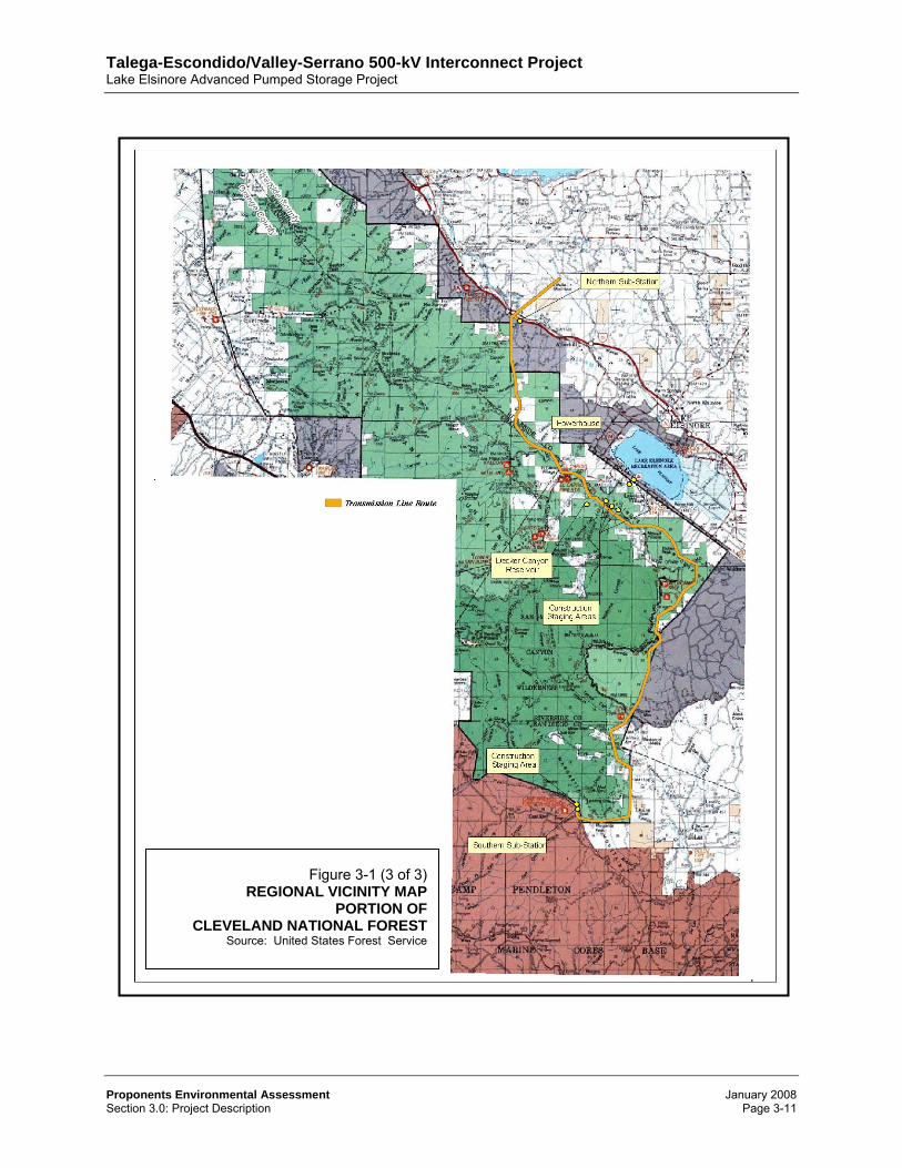
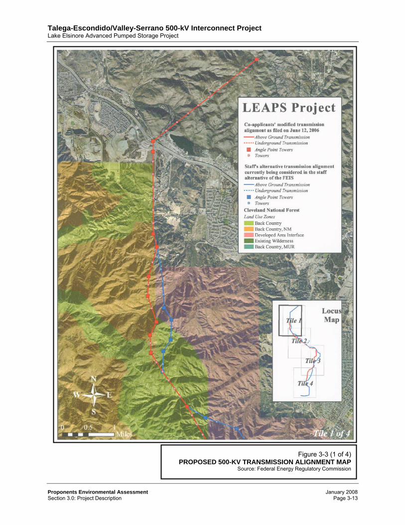
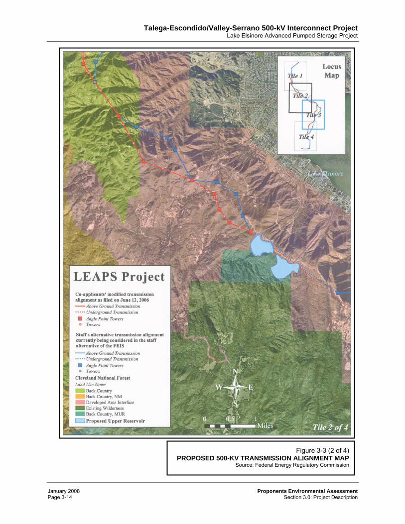
lands located within the Lake Mathews-Estelle Mountain Reserve. Although the two energy projects are comprised of more than transmission lines, excluding the proposed improvements to SDG&E’s approximately 51-mile long Talega-Escondido 230-kV transmission line, the transmission aspects of both projects provide a broad overview of the projects’ geographic extent. Presented in Figure 3-3 (Proposed 500-kV Transmission Alignment Map) are maps depicting the proposed approximately 30-mile long and 500-foot wide transmission alignment, as established by FERC and the Forest Service.3 This transmission alignment is common to both the LEAPS and TE/VS Interconnect projects. The proposed 500-kV transmission alignment is generally as reflected in FERC’s and USFS’ “staff alternative,” as presented in the FEIS.4 Once operational, the projects’ new 500-kV transmission lines would constitute a component of the interstate bulk transmission system. As illustrated, a substantial portion of the proposed new 500-kV transmission alignment traverses National Forest System (NFS) lands located within the 1,904,826-acre Cleveland National Forest (CNF). The CNF is comprised of three ranger districts (Trabuco, Palomar, and Descanso). The proposed projects are located in the Trabuco Ranger District (TRD) and on other public and private lands located in close proximal to that federal reservation. Within the TRD is the 39,450-acre San Mateo Canyon Wilderness, as established in 1984 (PL 98-425). That designated wilderness area is part of the National Wilderness Preservation System. None of the projects’ facilities encroach within the designated wilderness area established pursuant to the Wilderness Act of 1964 (PL 88-577). Operationally, the TE/VS Interconnect and LEAPS projects’ new transmission alignment will extend between and will serve to interconnect SCE’s existing 500-kV Valley-Serrano
3/ Actual right-of-way (ROW) width will be established in accordance with National Electrical Safety Code
(NESC) and Western Energy Coordinating Council (WECC) requirements, operational considerations, and Forest Service entitlements. Specific ROW requirements depend on the structure type, height, span, and conductor configuration. ROW requirements generally seek to take into account the height of the structure (150-178 feet) on either side of the centerline to avoid issues associated with structure failure. Beyond twice the height of the towers, an additional ROW distance of 50 feet is desired to allow equipment access in the event of a structural collapse.
4/ Federal Energy Regulatory Commission, Final Environmental Impact Statement for Hydropower License – Lake Elsinore Advanced Pumped Storage Project, FERC Project No. 11858, FERC/EIS-0191F, January 2007.
Talega-Escondido/Valley-Serrano 500-kV Interconnect Project Lake Elsinore Advanced Pumped Storage Project
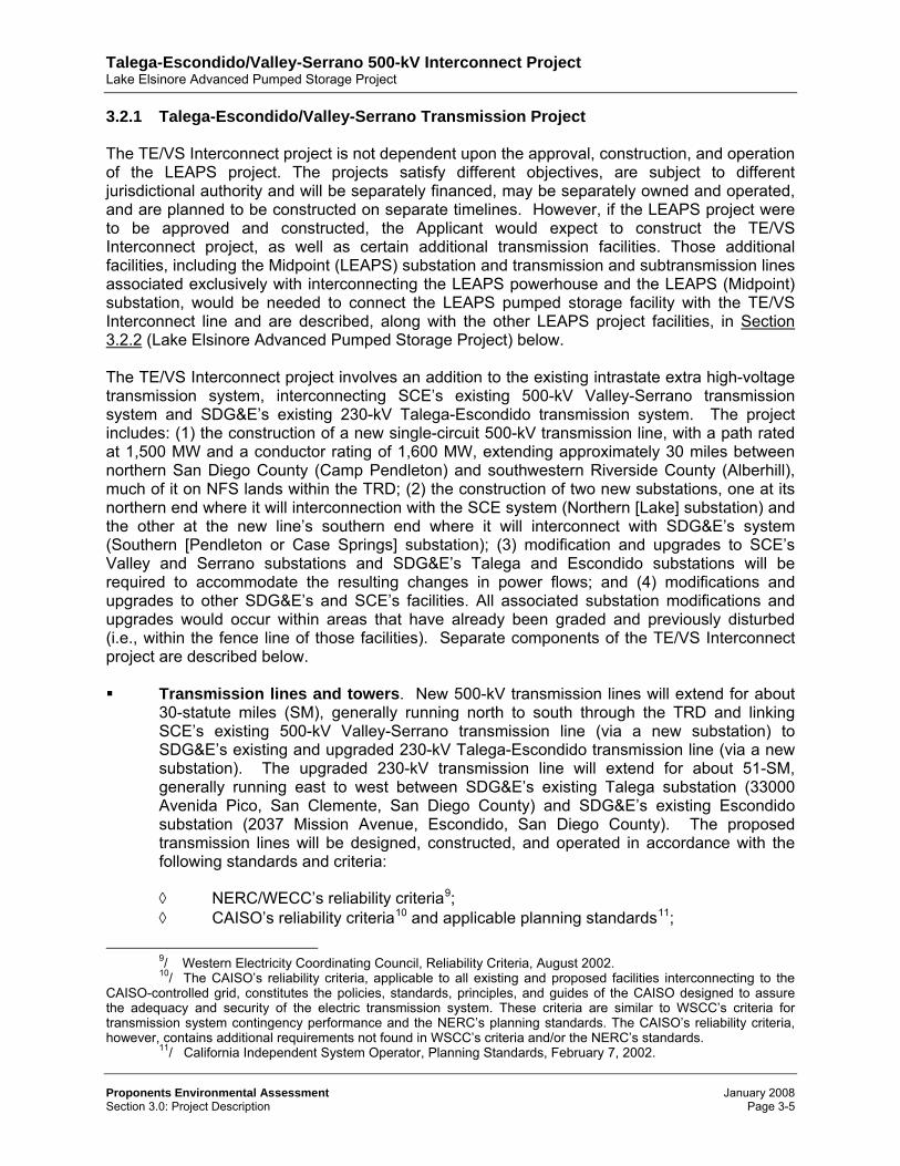
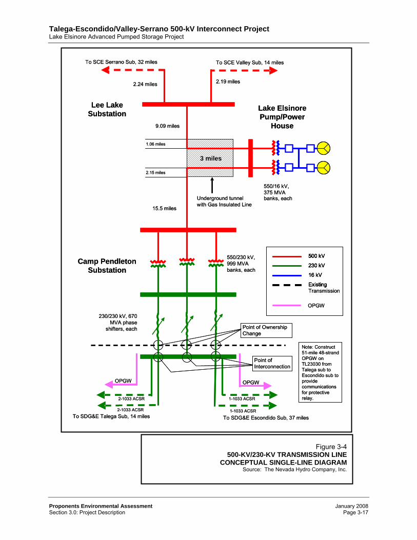
transmission line on the north via a new substation located within the unincorporated area (Alberhill) of Riverside County, and SDG&E’s existing 230-kV transmission line on the south via a new substation located within the boundaries of Camp Pendleton in San Diego County. From the proposed new substation in the vicinity of Camp Pendleton, identified as the Southern (Pendleton or Case Springs5) substation, the new 230-kV transmission lines comprising the second Talega-Escondido circuit (Talega-Escondido No.2). The Talega-Escondido second circuit will be strung along existing SDG&E towers, extending westward to the existing Talega 230/138-kV substation (Camp Pendleton, Orange County) and eastward to the existing Escondido 230/138-kV substation (City of Escondido, San Diego County).6 Presented in Figure 3-4 (500-kV/230-kV Transmission Line – Conceptual Single-Line Drawing) is a conceptual single-line drawing of the TE/VS Interconnect project. Depicted in Figure 3-5 (SDG&E 230-kV Transmission Line Upgrade Map [General])7 and in Figure 3-6 (SDG&E 230-kV Transmission Line Upgrade Map [Specific]) are maps illustrating the approximately 51-mile long existing Talega-Escondido 230-kV transmission alignment (Talega-Escondido No. 1). 3.2 Description of the Proposed Projects The State CEQA Guidelines define the “project” to mean “the whole of an action, which has a potential for resulting in either a direct physical change in the environment, or a reasonably foreseeable indirect physical change in the environment” (14 CCR 15378[a]). Although the Applicant is not seeking a CPCN for the LEAPS project (as licensed by FERC under a separate FERC proceedings), in recognition of the relationship between the two projects and the inclusion of both the LEAPS and TE/VS Interconnect projects in a single National Environmental Policy Act (NEPA) document,8 from an environmental perspective, it may be helpful for a reader to understand the hydropower project’s association with and relationship to the “stand-alone” TE/VS Interconnect project (as permitted by the CPUC). As such, both the TE/VS Interconnect project and the LEAPS project are separately described below. As noted, the LEAPS and TE/VS Interconnect projects “share” a number of common elements. Table 3-1 (TE/VS Interconnect Project and LEAPS Project Facilities) provides a comparison between the physical facilities associated with the two projects. As noted, the TE/VS Interconnect project does not include certain facilities that are integral components of the LEAPS project including, but not necessarily limited to, the existing afterbay (Lake Elsinore), new forebay (Decker Canyon), new intake and outlet structures, new penstocks, new
5/ The proposed new Southern substation is identified herein as either “Pendleton” or “Case Springs” since
the name of that substation has not been determined in consultation with State and federal regulators. The two names are intended to be synonymous and refer to the location and the facility described herein. The names for each of the individual facilities presented herein are for descriptive purposes only. The names assigned to those facilities have no relevancy in the context of the projects’ environmental review and may be subsequently changed or modified by the permitting and/or administrating agencies.
6/ SDG&E’s 230-kV Talega-Escondido transmission line was originally licensed and constructed using double-circuit structures with only one circuit installed. Necessary transmission upgrades to support the projects’ import capability would include installing the second 230-kV circuit on the existing transmission structures and modifying the existing substations at Talega and Escondido (Source: California Public Utilities Commission and Bureau of Land Management, Notice of Preparation of an Environmental Impact Report/Environmental Impact Statement by the California Public Utilities Commission and the Bureau of Land Management for the San Diego Gas & Electric Company Valley-Rainbow 500 kV Interconnect Project, 2001).
7/ San Diego Gas & Electric Company, A.01-03-036. 8/ Federal Energy Regulatory Commission and United States Department of Agriculture, Forest Service,
Final Environmental Impact Statement for Hydropower License – Lake Elsinore Advanced Pumped Storage Project, FERC Project No. 11858, FERC/EIS-0191F, January 2007.
Talega-Escondido/Valley-Serrano 500-kV Interconnect Project Lake Elsinore Advanced Pumped Storage Project
powerhouse (Santa Rosa), new LEAPS (Midpoint) substation, and the short-stub 500-kV interconnection between the new LEAPS (Midpoint) substation and the point of juncture.
3.2.1 Talega-Escondido/Valley-Serrano Transmission Project The TE/VS Interconnect project is not dependent upon the approval, construction, and operation of the LEAPS project. The projects satisfy different objectives, are subject to different jurisdictional authority and will be separately financed, may be separately owned and operated, and are planned to be constructed on separate timelines. However, if the LEAPS project were to be approved and constructed, the Applicant would expect to construct the TE/VS Interconnect project, as well as certain additional transmission facilities. Those additional facilities, including the Midpoint (LEAPS) substation and transmission and subtransmission lines associated exclusively with interconnecting the LEAPS powerhouse and the LEAPS (Midpoint) substation, would be needed to connect the LEAPS pumped storage facility with the TE/VS Interconnect line and are described, along with the other LEAPS project facilities, in Section 3.2.2 (Lake Elsinore Advanced Pumped Storage Project) below. The TE/VS Interconnect project involves an addition to the existing intrastate extra high-voltage transmission system, interconnecting SCE’s existing 500-kV Valley-Serrano transmission system and SDG&E’s existing 230-kV Talega-Escondido transmission system. The project includes: (1) the construction of a new single-circuit 500-kV transmission line, with a path rated at 1,500 MW and a conductor rating of 1,600 MW, extending approximately 30 miles between northern San Diego County (Camp Pendleton) and southwestern Riverside County (Alberhill), much of it on NFS lands within the TRD; (2) the construction of two new substations, one at its northern end where it will interconnection with the SCE system (Northern [Lake] substation) and the other at the new line’s southern end where it will interconnect with SDG&E’s system (Southern [Pendleton or Case Springs] substation); (3) modification and upgrades to SCE’s Valley and Serrano substations and SDG&E’s Talega and Escondido substations will be required to accommodate the resulting changes in power flows; and (4) modifications and upgrades to other SDG&E’s and SCE’s facilities. All associated substation modifications and upgrades would occur within areas that have already been graded and previously disturbed (i.e., within the fence line of those facilities). Separate components of the TE/VS Interconnect project are described below. Transmission lines and towers. New 500-kV transmission lines will extend for about
30-statute miles (SM), generally running north to south through the TRD and linking SCE’s existing 500-kV Valley-Serrano transmission line (via a new substation) to SDG&E’s existing and upgraded 230-kV Talega-Escondido transmission line (via a new substation). The upgraded 230-kV transmission line will extend for about 51-SM, generally running east to west between SDG&E’s existing Talega substation (33000 Avenida Pico, San Clemente, San Diego County) and SDG&E’s existing Escondido substation (2037 Mission Avenue, Escondido, San Diego County). The proposed transmission lines will be designed, constructed, and operated in accordance with the following standards and criteria: ◊ NERC/WECC’s reliability criteria9; ◊ CAISO’s reliability criteria10 and applicable planning standards11;
9/ Western Electricity Coordinating Council, Reliability Criteria, August 2002. 10/ The CAISO’s reliability criteria, applicable to all existing and proposed facilities interconnecting to the
CAISO-controlled grid, constitutes the policies, standards, principles, and guides of the CAISO designed to assure the adequacy and security of the electric transmission system. These criteria are similar to WSCC’s criteria for transmission system contingency performance and the NERC’s planning standards. The CAISO’s reliability criteria, however, contains additional requirements not found in WSCC’s criteria and/or the NERC’s standards.
11/ California Independent System Operator, Planning Standards, February 7, 2002.
Talega-Escondido/Valley-Serrano 500-kV Interconnect Project Lake Elsinore Advanced Pumped Storage Project
◊ CPUC’s “Construction and Operation of Power and Communication Lines” (General Order [GO] 52), “Rules for Overhead Line Construction” (GO-95), "Rules for Construction of Underground Electric Supply and Communications Systems" (GO-128), and “Rules for Planning and Construction of Electric Generation, Line, and Substation Facilities in California” (GO-131-D), current avian protection plan guidelines12 and suggested practices13; and
◊ SCE and SDG&E design standards, as applicable, and other applicable State and local codes.
As specified by the Forest Service on NFS lands: (1) transmission lines shall be non-specular (non-reflective) and neutral in coloration; (2) support towers shall be custom-colored to harmonize with the natural vegetation and sky; (3) towers beyond 3/4 mile of sensitive viewpoints shall visually recede into the natural appearing landscape; (4) support towers within the foreground (approximately 3/4 mile of sensitive viewpoints) shall typically be of monopole design; and (5) vegetation and ground clearing at the foot of each tower and between towers will be limited to the clearing necessary to comply with electrical safety requirements. Final tower designs and specifications shall be determined in cooperation with the CAISO, SCE, and SDG&E. Except where otherwise noted, new 500-kV single-circuit transmission towers, as illustrated in Figure 3-7 (Typical Single-Circuit 500-kV Steel-Lattice Tower), would be erected between SCE’s existing Valley-Serrano line and the Applicant’s proposed new Southern (Pendleton or Case Springs) substation. The four-legged transmission towers will be constructed of full galvanized lattice steel angle members connected with steel bolts. The structure would carry the electrical conductors in either a horizontal or delta configuration. Towers, which will generally vary in heights between 150-178 feet, will be located along the centerline of a new 500-foot wide right-of-way14 (ROW). A narrower ROW may be established both on public lands within the TRD and/or on private lands located outside National Forest boundaries. Between the northern boundary of the TRD (at the point where the transmission line departs the National Forest) and the Northern (Lake) substation, 500-kV tubular steel monopoles will be erected. A typical single-pole, tubular steel tower is illustrated in Figure 3-8 (Typical Single-Circuit 500-kV Monopole Tower). Alternatively, as illustrated in Figure 3-9 (Typical Single-Circuit 500-kV Tubular-Steel Tower), tubular steel H-frame towers will be constructed if required for structural or other reasons. The path rating of the TE/VS Interconnect line is expected to be 1,500 MW. The conductor size is planned at 2,156 Kcmil (thousands of circular mils) aluminum
12/ Edison Electric Institute Avian Power Line Interaction Committee and United States Fish and Wildlife
Service, Avian Protection Plan Guidelines, April 2005. 13/ Edison Electric Institute Avian Power Line Interaction Committee and the California Energy Commission,
Suggested Practices for Avian Protection on Power Lines: The State of the Art in 2006, PEIR Final Project Report, CEC-500-2006-022, 2006.
14/ As part of the FERC licensing processes for the LEAPS project (FERC Project No. 11858-002), a 500-foot wide study area was examined in the “Final Environmental Impact Statement for Hydropower License – Lake Elsinore Advanced Pumped Storage Project, FERC Project No. 11858, FERC/EIS-0191F” (FERC/USFS, January 2007). The wide of that study area was defined in discussions with FERC and the Forest Service so as to ensure reasonable flexibility in the siting of the proposed transmission facilities. The wide of the study area is not necessarily indicative of the wide of the transmission right-of-way which will be established and authorized by those agencies under the FERC hydropower license and/or the USFS special use permit. The Applicant is not seeking federal right-of-way authorization in excess of that required for the safe operation of the proposed projects.
Talega-Escondido/Valley-Serrano 500-kV Interconnect Project Lake Elsinore Advanced Pumped Storage Project
conductor steel reinforced (ACSR) spaced 18-inches apart. The connection will have a planned ampacity rating of at least 1,623 amps. All 500-kV air-insulated circuits will be twin-bundled 2156 “Bluebird“ ACSR, or equivalent. The overhead shield wires, employed to protect the electrical conductors from lighting strikes, would be aluminium-coated steel-stranded wire with a fiber-optic core for communication purposes. Some of the fibers in the fiber-optic core would be used for control and monitoring of protective relaying and communication equipment between facilities. Transmission towers will consist of tangent (suspended) type structures, where the conductors approach and depart the structures in a straight line, and heavier structures, including both angle structures that suspend the conductors and allow limited changes in line direction and dead-end structures which allow for more substantial changes in line direction. Based on the nature of the existing terrain and requirements for adequate ground clearance, tower-to-tower spacing for new steel-lattice towers will range between a minimum of about 400 feet to a maximum of about 1,600 feet. The span length for tubular steel poles will range between about 1,000-1,500 feet, depending on anticipated line sag and required clearance from existing terrain and vegetation. The exact quantity and precise placement of towers will be determined during the final design phase. Typical structure foundations will require four augured, cast-in-place concrete piles about 3-foot diameter for the lattice structures (four foundations per structure) and about 9-foot in diameter for tubular steel structures (one foundation per structure). The size and number of piles will vary based on the type of structure, load, and soil conditions encountered at each tower site. For the larger angle or dead-end structures, foundation holes would likely be larger in diameter because of the additional loads and tension. An approximately 1.7-mile segment of the proposed transmission line will be placed in an underground vault rather than an overhead structures. The remaining line segments will be overhead lines (OHL). The underground circuits will be gas-insulated lines (GIL),15 rated at 4,000 amps (A) continuous and 63 kiloamps (kA) short circuit. The GIL-vault layout is as generally illustrated in Figure 3-10 (Gas-Insulated Line [GIL] Vault Layout). As illustrated in Figure 3-11 (GIL-OHL Transition Station North) and Figure 3-12 (GIL-OHL Transition Station South), transition stations between the GIL and the overhead line (OHL) will be constructed at the northern and southern terminus of the GIL vault. That transmission line is electrically depicted in Figure 3-13 (GIL-Vault Single-Line Diagram Transition to Powerhouse). Where authorized by the USFS, temporary and/or permanent access roads will be constructed to select tower sites within the TRD and maintained by the Applicant. As illustrated in Figure 3-14 (Preliminary Tower Placement and Access Road Locations), new unimproved tower access roads will be about 14-feet wide, extending from existing improved or unimproved roads located in proximity to those tower sites. Culverts or other drainage structures will be installed as necessary to allow passage of heavy equipment across any affected drainages. In locations where access roads are not illustrated or not authorized or not permitted by the Forest Service or by other governmental agencies, tower construction and on-going tower and line maintenance activities will be conducted through the use of off-site-based helicopters and ground crews accessing each area
15/ Although the Applicant is proposing a GIL system, other underground technologies and design options
that may be available include fluid-filled polypropylene paper laminate (PPL), cross-linked polyethylene (XLPE), high-pressure fluid-filled (HPFF), and extruded-dielectric transmission cables. Other underground cable technologies have been considered and TNHC’s analysis supports the use of GIL as the appropriate application for this project.
Talega-Escondido/Valley-Serrano 500-kV Interconnect Project Lake Elsinore Advanced Pumped Storage Project
from existing roadways. Any new USFS-authorized access roads would serve the duel purpose of facility construction, maintenance, and fire suppression access. Should any temporary or permanent access roads cross jurisdictional streams, appropriate stream crossings, including gradients and culverts acceptable to the USFS and subject to applicable ACOE and SWRCB permit requirements, will be installed and maintained to allow water to flow beneath or across the road in a manner preventing or substantially minimizing any potential erosion and maintains existing wildlife functions.16 Lattice towers will be broken into several smaller sections for helicopter transport and on-site assembly. Foundations for remote towers will be hand dug by ground crews using smaller equipment delivered to those sites by helicopter or helicopter-mounted auger. After the towers are erected, the structures will be rigged with insulator strings and stringing sheaves at each ground wire and conductor position. During wire installation, where appropriate, guard structures will be erected adjacent to highways, public roadways, power lines, structures, and other obstacles. Guard structures would consist of H-framed wood poles placed on either side of the obstacle to prevent ground wire, conductors, or equipment from falling onto the obstacle. Guard structures will be removed following the completion of conductor installation. Pilot lines will be pulled from structure to structure and threaded through the stringing sheaves at each structure. This phase of work may be accomplished through the use of helicopters to minimize disturbance within the transmission alignment. Following pilot lines, a larger diameter line will be attached to the conductors to pull them onto structures. The shield wire and conductors will be strung using powered pulling equipment and powered breaking or equipment tensioning equipment at opposite ends. Once energized, the transmission lines will be regularly inspected by ground and aerial patrols. Maintenance activities will be in accordance with the operator’s established maintenance schedule and the general provisions of the memorandum of understanding (MOU) between the USFS, Edison Electric Institute, and other federal agencies creating a framework for cooperative ROW integrated vegetation management (IVM) practices and establishing standards relating to system reliability and safety.17 Unless otherwise provided, those standards include the following: ◊ American National Standards Institute (ANSI) Standards A30018; ◊ American National Standards Institute, Inc., ANSI Z133.1-199419; ◊ Institute of Electrical and Electronics Engineers (IEEE) Standard 516-200320; ◊ North American Electric Reliability Council (NERC) Reliability Standards;
16/ United States Department of Agriculture, Fish Passage Through Culverts, FHWA-FL-90-006, Forest
Service, November 1990; Moll, Jeffry E.. Minimizing Low Volume Road Water Displacement, 9977 1804P, United States Department of Agriculture, United States Forest Service, August 1999, revised July 2003.
17/ Memorandum of Understanding among the Edison Electric Institute and the United States Department of Agriculture Forest Service and the United States Department of the Interior, Bureau of Land Management, Fish and Wildlife Service, National Park Service, and the United States Environmental Protection Agency (FS MOU-06-SU-11132426-158, BLM MOU-WO-220-2006-09), March 3, 2006.
18/ American National Standards Institute, ANSI A300 – 2001, Tree Care Operations – Tree, Shrub and Other Woody Plant Maintenance – Standard Practices (revision and redesignation of ANSI A300-1995) (Includes Supplements).
19/ American National Standard for Tree Care Operations--Pruning, Trimming, Repairing, Maintaining, and Removing Trees, and Cutting Brush-Safety Requirements.
20/ Institute of Electrical and Electronics Engineers, Guide for Maintenance Methods on Energized Power Lines.
Talega-Escondido/Valley-Serrano 500-kV Interconnect Project Lake Elsinore Advanced Pumped Storage Project
Figure 3-1 (1 of 3) REGIONAL VICINITY MAP
PORTION OF RIVERSIDE, ORANGE, AND SAN DIEGO COUNTIES
Figure 3-5 SDG&E 230-KV TRANSMISSION LINE UPGRADE MAP (GENERAL)
Source: California Public Utilities Commission/DUDEK & Associates
Note: This map is extracted from a separate CPUC proceeding and is presented to illustrate the existing 230kV Talega-Escondido transmission alignment. Certain facilities illustrated herein are not associated with the proposed projects.