46
SuDS In London: A Design Guide Chapter 3 - 42 3.0 SuDS Components Canary Wharf
SuDS In London: A Design Guide Chapter 3 - 42
3.0 SuDS Components
Canary Wharf

Chapter 3 - 43
3.1 What is appropriate for London?
Sustainable drainage systems are a
combination of components on-and off-site
that make the most of all-round benefits
as described in chapter 1. This section
explains the SuDS components that may be
appropriate for use in London. Introducing and
integrating hard and soft engineering requires a
holistic design approach.
SuDS use a variety of components to manage
water quality and volume and to deliver
amenity and biodiversity. An understanding of
topography and local surface water discharge
options are critical in identifying the most
suitable combination of components, with
particular attention to:
• Where the rainwater lands and how it is
collected (source)
• Identifying conveyance options (pathway)
• Determining the most appropriate
discharge points (receptor)
SuDS should maximise potential by ‘thinking
upstream’ that is, they should take advantage
of specific upstream source control measures.
A number of case studies illustrating the
application of various components from
a variety of sources and locations are
incorporated within this chapter Integrated SuDS components: wet Integrated SuDS components: dry
SuDS In London: A Design Guide Chapter 3 - 44
SuDS components in the street could include
one or a number of the following depending on
the context, opportunity and site constraints:
• Permeable pavements with robust surfaces
which allow rainwater to pass through
them. Attenuated in granular subbase
material or below ground structures, this
can replenish groundwater or discharge at
a controlled rate into a sewer
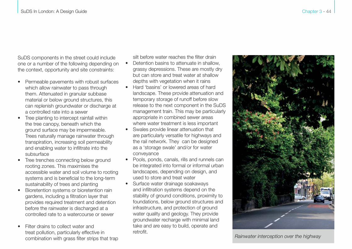
• Tree planting to intercept rainfall within
the tree canopy, beneath which the
ground surface may be impermeable.
Trees naturally manage rainwater through
transpiration, increasing soil permeability
and enabling water to infiltrate into the
subsurface
• Tree trenches connecting below ground
rooting zones. This maximises the
accessible water and soil volume to rooting
systems and is beneficial to the long-term
sustainability of trees and planting
• Bioretention systems or bioretention rain
gardens, including a filtration layer that
provides required treatment and detention
before the rainwater is discharged at a
controlled rate to a watercourse or sewer
• Filter drains to collect water and
treat pollution, particularly effective in
combination with grass filter strips that trap
silt before water reaches the filter drain
• Detention basins to attenuate in shallow,
grassy depressions. These are mostly dry
but can store and treat water at shallow
depths with vegetation when it rains
• Hard ‘basins’ or lowered areas of hard
landscape. These provide attenuation and
temporary storage of runoff before slow
release to the next component in the SuDS
management train. This may be particularly
appropriate in combined sewer areas
where water treatment is less important
• Swales provide linear attenuation that
are particularly versatile for highways and
the rail network. They can be designed
as a ‘storage swale’ and/or for water
conveyance
• Pools, ponds, canals, rills and runnels can
be integrated into formal or informal urban
landscapes, depending on design, and
used to store and treat water
• Surface water drainage soakaways
and infiltration systems depend on the
stability of ground conditions, proximity to
foundations, below ground structures and
infrastructure, and protection of ground
water quality and geology. They provide
groundwater recharge with minimal land
take and are easy to build, operate and
retrofit.Rainwater interception over the highway

Chapter 3 - 45
Opportunities for integration of other SuDS
components in the management train may be
appropriate, depending on the disposition of
assets and through constructive partnerships.
For example and with reference to TfL these
might include:
• building roofs (depot and station office etc.)
• car parks (station, schools and office etc.)
• ancillary structures (platform canopies,
substations and bus stops etc.)
• platforms
• embankments
These assets may be viable for designing in, or
retrofitting:
• ‘living roofs’ (green, brown or blue roofs) to
provide source control
• water butts and tanks to intercept and
harvest rainfall by disconnecting and
diverting downpipes
• rain gardens to create temporary localised
ponding for roof runoff, allowing plants and
trees to benefit from that ponding
• rainwater planters to attenuate in above
ground planters, with integral storage and
slow release
In the urban environment of London’s
public realm and in surface water flood risk
zones, there are many opportunity for SuDS
in various scales and configurations. For
example:
• integrated water management strategies
that can be delivered as part of re-
development or transport improvement
schemes
• de-paving, bioretention and street tree
planting, retrofitted as part of already
planned annual highways maintenance,
repair and improvement programmes
• permeable pavement construction
• re-purposing linear green infrastructure,
such as verges and embankments along
roads, railways and waterways
• retrofitting for cycleways and greening to
address the cycling and healthy streets
agenda
• decompacting existing parkland soils
• repurposing existing greenspace for
swales, rain gardens and bioretention
components
• bioremediation of contaminated site
• rainwater harvesting, by installing water
butts and storage tanks
• bespoke solutions to meet specific
situations, management regimes, project
drivers and community aspiration and
campaigns (such as Love the Lea and
SuDS for Schools)
• retrofitting green infrastructure, in particular,
living roofs, green walls and street tree
planting
• protecting existing assets that are
effectively operating as a SuDS
components, including London’s urban
forest (including street trees), parks
and gardens, verges and infrastructure
corridors
The SuDS components are described in more
detail in the order found in CIRIA C753 The
SuDS Manual.
SuDS In London: A Design Guide Chapter 3 - 46
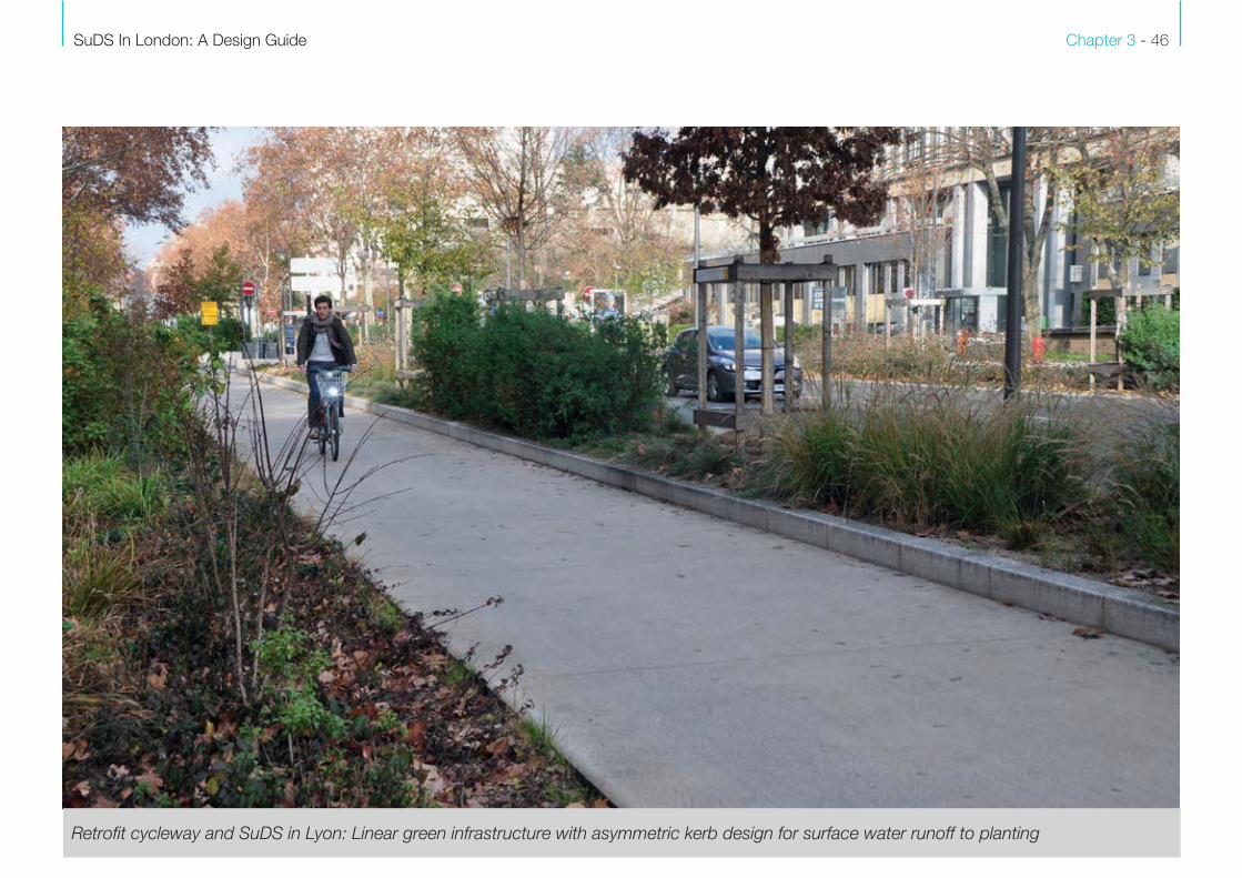
Retrofit cycleway and SuDS in Lyon: Linear green infrastructure with asymmetric kerb design for surface water runoff to planting
Chapter 3 - 47
3.2 Structures
Some of the TfL structures within London’s
streets include stations (although many are
over station developments), walls, bus stops,
offices and transport related infrastructure.
All provide an opportunity to install living roofs
and green wall systems that intercept and
retain rainwater runoff at source depending on
operation constraints and requirements.
Living roofs are an effective way to integrate
green infrastructure no matter how intense
the development. The term living roofs include
‘green’ (planted), ‘blue’ (water attenuation) and
‘brown’ (recycled substrate) roofs. They all
effectively integrate significant areas of source
control SuDS, without taking up space on the
ground. Typically the three types of living roofs
can be characterised by:
• Extensive roofs: these have varying
substrate depths and vegetation that
generally includes grasses and wildflowers,
creating minimal loading on structures.
• Intensive roofs: these typically have
deeper substrates supporting a range of
vegetation. This puts larger loadings on the
structure
• Blue roofs which attenuate through
vegetated substrate specification and
drainage design
’Green walls’ are vegetated walls that are
supported on cables, cellular systems or can
be self-clinging and unsupported. They can be
proprietary systems with irrigation, or formed
over time by planting climbing plants into the
ground that are more self-sufficient.
BenefitsLiving roofs and green walls provide multiple
benefits and are an important component of
the green infrastructure vision for London. They
reduce rainwater runoff rates and the urban
heat island effect, and filter air pollution.
Benefits include:
Amenity: living roofs enhance outlook over the
roofscape while providing amenity where there
may be little space on the ground. Rooftop
parks and gardens act as an educational
and urban farming resource. Green walls
soften the hard city environment, reducing air
temperatures, while being space efficient.
Biodiversity: living roofs safeguard, enhance,
restore and create habitat with no additional
land take. They provide important habitat
stepping stones and connectivity within the
built environment and contribute to London’s
natural capital. In particular, they provide refuge
for rare invertebrate populations. Green walls
provide vertical habitats for nesting and food
for pollinators.
Interception: living roofs act as source control
and intercept rainwater where flora and fauna
benefit. Green walls integrate recycled water
systems for irrigation, if not planted in the
ground.
Attenuation: living roofs attenuate surface
water by providing storage, water reduction
through evaporation and transpiration, enabling
a reduced discharge rate.
Filtration: living roofs treat water through a
variety of physical, biological and chemical
treatment processes, within the soil and root
uptake zones. They regulate surface water
runoff temperature that could adversely affect
ecology of local water bodies.
Design considerationsLiving roofs can be retrofitted or designed as
an integral part of re-development. If retrofitted,
they provide significant SuDS performance in
terms of achieving greenfield runoff rates or
betterment targets. Access, safety and edge
protection needs to be considered at an early
design stage.

SuDS In London: A Design Guide Chapter 3 - 48
Green wall: Oslo Living roof: Copenhagen
Exceedance: roof drainage design should
counter the risks associated with exceedance.
Interception to recycle rainwater for irrigation
should be integrated where possible.
Structural resilience: living roofs add additional
loading to a roof structure, depending on the
material used, in the form of a dead load.
This is typically around 0.7 to 5.0 kN/m, with
imposed loads up to 10 kN/m.
Fire resistance: fire risks can be managed
through the use of appropriate materials
and design. Ensure vegetation is kept at a
minimum distance away from vulnerable areas
such as openings and vents.
Substrate: soils and growing media can be
formed of recycled material, which support
different potential for flora and fauna. Varying
depths of substrate, together with integration
of dead wood and aggregates within a single
roof landscape, create different microclimates
and the potential for habitat diversity.
Vegetation: living roofs support a variety
of plants for amenity, biodiversity and food
growing. The species selection, whether
seeded, self-seeded, pre-grown or planted
should be adapted to microclimate and
substrate specification. Roof conditions
Chapter 3 - 49
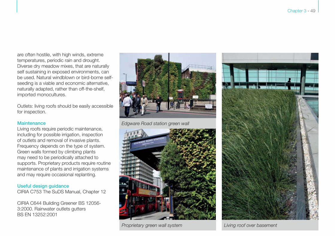
Living roof over basementProprietary green wall system
Edgware Road station green wall
are often hostile, with high winds, extreme
temperatures, periodic rain and drought.
Diverse dry meadow mixes, that are naturally
self sustaining in exposed environments, can
be used. Natural windblown or bird-borne self-
seeding is a viable and economic alternative,
naturally adapted, rather than off-the-shelf,
imported monocultures.
Outlets: living roofs should be easily accessible
for inspection.
MaintenanceLiving roofs require periodic maintenance,
including for possible irrigation, inspection
of outlets and removal of invasive plants.
Frequency depends on the type of system.
Green walls formed by climbing plants
may need to be periodically attached to
supports. Proprietary products require routine
maintenance of plants and irrigation systems
and may require occasional replanting.
Useful design guidanceCIRIA C753 The SuDS Manual, Chapter 12
CIRIA C644 Building Greener BS 12056-
3:2000. Rainwater outlets gutters
BS EN 13252:2001

SuDS In London: A Design Guide Chapter 3 - 50
Structures - Case study 1
Location Takparken
Malmo, Sweden
Date 2010
SuDS Components
Living Roof
ObjectivesTo provide a destination space and method
of source control for rainwater.
Outcome
The Takparken green space is on the
roof of a Malmö shopping mall. It spans
over 27,000m² and is considered one
of the largest green roofs in the world. It
is dominated by sedum planted stylised
hills with elements of undulating perennial
plantings with some larger shrubs. The roof
is accessible to the public and provides an
outdoor amphitheatre, seating and botanical
interpretation. The roof intercepts rainfall at
source as well as providing an important
biodiverse habitat.
Takparken: Sedums and perennials Takparken: Roof plan
Chapter 3 - 51
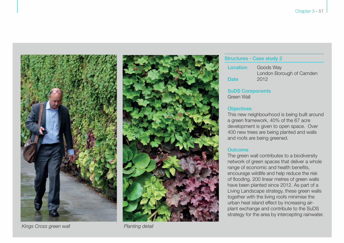
Structures - Case study 2
Location Goods Way
London Borough of Camden
Date 2012
SuDS Components
Green Wall
ObjectivesThis new neighbourhood is being built around
a green framework, 40% of the 67 acre
development is given to open space. Over
400 new trees are being planted and walls
and roofs are being greened.
Outcome
The green wall contributes to a biodiversity
network of green spaces that deliver a whole
range of economic and health benefits,
encourage wildlife and help reduce the risk
of flooding. 200 linear metres of green walls
have been planted since 2012. As part of a
Living Landscape strategy, these green walls
together with the living roofs minimise the
urban heat island effect by increasing air-
plant exchange and contribute to the SuDS
strategy for the area by intercepting rainwater.
Kings Cross green wall Planting detail

SuDS In London: A Design Guide Chapter 3 - 52
Structures - Case study 3
Location New Burlington Mews
City of Westminster
Date 2014
SuDS Components
Green wall
ObjectivesTo create a living wall to improve the outlook
from surrounding buildings and enhance
biodiversity in the mews, in line with Crown
Estate and Westminster Council objectives.
Outcome
The ‘living wall’ wraps around the building
forming a green backdrop to the office
reception area. Three metre tall beech hedge
plants were advance procured and installed
behind rhythmic architectural metal work. The
hedge has been interplanted with hydrangea,
parthenocissus and lonicera sp. that will grow
over the frame and provide biodiversity and
seasonal interest to the mews as well as an
area to intercept rainwater.
After Before
Images courtesy of J & L Gibbons
Chapter 3 - 53
London’s parks, gardens and greenspace
provide large scale SuDS infiltration in the open
soil, coupled with the interception that parkland
trees provide. Intense pedestrian use can affect
soil capacity for infiltration through compaction.
Decompaction is therefore important to boost
the existing green infrastructure’s ability to
intercept rainfall.
Designed infiltration systems include the
following sustainable drainage components:
• Soakaways: pits that temporarily provide
storage before infiltration
• Trenches: linear soakaways and strips of
grass that are predominantly dry, but in
heavy rainfall, fill up and store water for a
period of time before infiltration
• Infiltration basins: depression performing
the same function as trenches
• Blankets: open, flat areas of grass,
allowing infiltration over a wider area than
a trench or basin. This might be below a
car park where the storage layer is part
of the pavement construction, or below
playgrounds or sports pitches
These components are designed to promote
infiltration where capacity and permeability
of soils permits and where the depth to
groundwater allows.
BenefitsInfiltration components allow groundwater to
be replenished. They can incorporate marginal
and wetland habitat. Planting introduced
to improve ecology slows the flow rate by
retaining the drainage properties of the soil,
creating a more effective SuDS component.
They can be used to manage overflows from
rainwater collection systems, such as water
butts and runoff from small areas, such as
drives and roofs.
Design considerationsInfiltration components can be retrofitted,
designed as a series of small linked elements,
or as a single larger one.
Runoff flow to be directed to a SuDS infiltration
component can be collected laterally along
the edge of an impermeable surface. Kerb
openings and roadside lateral inlets help to
direct, control and reduce flow velocities.
A minimum of one metre from the base of the
infiltration component to maximum ground
water level is required. Upstream pre-treatment
should be integrated where possible to remove
sediment and silt.
Performance of the components may be
compromised if surface soils become
3.3 Infiltration systems
compacted, therefore they should be designed
to withstand high intensity pedestrian use.
Performance depends on the capacity of the
soils surrounding the component. When rainfall
rate exceeds the design capacity, a flow route
or temporary storage should be provided.
Soil infiltration can be enhanced by:
• Managing construction traffic to prevent
compaction during construction
• Mixing sand with soil to retain its drainage
properties
• Ensuring tight construction tolerances are
adhered to
• Reusing existing topsoil that allows the
inherent seed bank in the soil to regenerate
quickly, reducing erosion, enhancing the
potential for infiltration
• Soil decompaction
MaintenanceThis can usually form part of the wider routine
landscape maintenance. Control structures
require periodic inspection. Existing parkland,
particularly in critical drainage zones that
are subject to intensity of use should be
periodically decompacted.
Useful design guidanceCIRIA C753 The SuDS Manual, Chapter 13

SuDS In London: A Design Guide Chapter 3 - 54
Hyde Park: London’s parks naturally provide existing large scale SuDS

Chapter 3 - 55
Infiltration systems - Case study 4
Location Streatham Common South
London Borough of Lambeth
Date 2013
SuDS components
De-paving
Tree planting
Kerb inlets
ObjectivesStreatham Common South falls within the
Streatham Critical Drainage Area (CDA).
The project included implementation of a
raingarden to alleviate flood risk and was
completed within a standard highway
maintenance scheme.
Outcome
Pavement SuDS, where inserted with verges,
replaced concrete dished channels. These
slow surface water drainage into the sewer
system. Modeling undertaken has shown that
the grass verge can theoretically remove 6m³
of surface water runoff in a 1 in 100 year 6
hour storm event.
Before
After
RE-SHOOT
RE-SHOOT
Images courtesy of Owen Davies
Kerb inlet and de-pave detail

SuDS In London: A Design Guide Chapter 3 - 56
Infiltration systems - Case study 5
Location 50 & 60 Reedworth Street
LB Lambeth
Date 2012
SuDS Components
Permeable paving
ObjectivesTo increase the permeability of front gardens.
Outcome
The paving over of front gardens in London
is a major issue and contributes to the
risk of surface water flooding. This project
highlighted how hard standing can be
removed without affecting parking. Residents
were supported in changing materials
including by the provision of tools, technical
advice and practical assistance. The
initiative has increased the permeability of
the front gardens and improved streetscape
aesthetics.
Images courtesy of Owen Davies
After with gravel and plantingDe-paving of private front gardens
Chapter 3 - 57
3.4 Filter strips
Filter strips are uniformly graded, gently sloping
areas of grass that allow water to flow as a
sheet towards a swale, bioretention system
or filter drain. They provide a simple form of
source control through pre-treatment of water,
to protect swales or filter drains from clogging
up with silt.
Filter strips are effective at intercepting
rainwater where the soil is sufficiently
permeable. The grass and vegetation slows
the water, allowing it to soak into the ground.
The plants help evaporate water and filter out
pollution.
BenefitsFilter strips create soft open space next to
impermeable areas. They can either be seeded
with amenity or meadow grass and managed
as long or short mown grass to support
biodiversity by providing:
• Foraging for birds and invertebrates
• Habitats for invertebrates
• ‘Stepping stone’ habitats, particularly in the
urban environment
Design considerationsFilter strips’ efficiency depends on length,
width, vegetation cover and soil specification.
Considerations include:
• Soil permeability
• Vegetation specification
• Height of vegetation and flow depth
• Peak flow velocity in relation to particulate
settlement
• Time of travel of runoff across the filter strip
• Protection of the strip from vehicular run-
over and development
• Designed for management by standard
landscape maintenance machinery
Filter strips should generally be greater than
2.5 metres wide, laid ideally to a one per cent
slope. Small filter strips that are 1-2 metres
long create effective connections between
broken kerb lines and the side slope of a
swale. Lengths of greater than five metres help
improve water quality performance.
Filter strips should be shielded with a kerb or
low-level barrier when they are next to a road
or car parking.
MaintenanceThis can form part of the wider landscape
maintenance operations, to ensure the
feature meets design performance standards.
Measures to prevent soil compaction are
particularly important.
Useful design guidanceCIRIA C753 The SuDS Manual, Chapter 15

SuDS In London: A Design Guide Chapter 3 - 58
Filter strip: Parkway retrofit

Chapter 3 - 59
3.5 Filter drains
Filter drains are usually linear components
along the roadside, which drain the roadway.
They are deep, narrow, gravel-filled trenches
that collect and move water. They often
include a perforated pipe at the base to
help drainage. Water flow through the gravel
removes some pollutants.
BenefitsFilter drains provide:
• Long and short term water storage during
a storm between the aggregate particles
• Silt removal, by eliminating suspended
sediment in the water
• A material that enhances biodiversity by
hosting micro-organisms and providing
a breeding ground for insects and
amphibians
Design considerationsFilter drains must be able to accommodate
high return periods (ie, one in 100 year
events) without suffering damage.
A geotextile (not a geomembrane) below the
surface of the aggregate traps silt to prevent
it clogging up the drain, while allowing
permeability.
Filter drains can be protected from silt by an
adjacent filter strip (see 3.4) or flow spreader.
Filter drains are usually 1-2 metres deep, with
a minimum depth of filter medium beneath
any inflow and outfall (0.5 metres) to ensure
reasonable levels of pollution removal.
These components can be located at the
bottom of embankments to intercept surface
water runoff or with filter strips on the
highway. Equally, they can be integrated as
an architectural feature in the public realm.
MaintenanceFilter drains require routine maintenance to
ensure vegetation or debris is removed from
the surface.
Useful design guidanceCIRIA C753 The SuDS Manual, Chapter 9
and 16
Open gravel filled joint

SuDS In London: A Design Guide Chapter 3 - 60
3.6 Wet swales and dry swales
Swales are linear components that provide
slow water conveyance. They provide
filtration, attenuation and storage of
surface water runoff from relatively small
catchment areas. They can be designed to
accommodate a range of rainfall events.
Generally, swales are sloping sided, flat
bottomed, vegetated open channels,
constructed at a gentle gradient. Steeper
gradients can be accommodated through the
use of check dams. Swale design is limited
by available space and is only effective when
close to catchment areas. Swales can be dry
or wet.
Dry swales allow surface water to infiltrate
and are designed to include a filter bed
with an underdrain to prevent waterlogging.
They can be lined or unlined depending on
groundwater levels. Where there is ground
contamination on brownfield sites, the design
should incorporate a liner, unless leaching
can be managed to an acceptable level.
The liner level should rest above the level of
seasonal high groundwater level.
Wet swale: Upton, Northants

Chapter 3 - 61
Wet swales retain water, behaving like a linear
wetland. They are best located where sites are
level and soils are poorly drained. Here they
can deliver amenity and biodiversity through
specific wetland planting. Storm water is
retained in the swale before it is conveyed to a
downstream outlet.
BenefitsConveyance: swales are a simple and effective
means of collecting and distributing runoff, or
as a means of conveying runoff on the surface,
while enhancing open space or the roadside
environment.
Filtration: engineered soils can help neutralise
contaminants and sedimentation caused
by runoff. Designs can include submerged
anaerobic zones to promote nutrient renewal.
Attenuation: swales are typically designed
to capture a one in 10 year storm event by
storing water within and on top of the filtration
media where the water can disperse over time.
Amenity: swales provide shallow linear planted
features in the landscape that are space-
efficient and adaptable to location. They
integrate well alongside highways, cycleways
or pathways. They allow bridging structures to Native marginal planting: Iris pseudacorus, yellow flag iris
SuDS In London: A Design Guide Chapter 3 - 62
the designer to establish the basic swale
dimensions.
Edge protection: as a component that
typically sits below pavement surface levels
and can hold standing water, the designer
should consider the edge detail.
Exceedance: swales are designed to provide
a level of storage that can accommodate
a one in 10 year storm event. The storage
capacity of a swale depends on its size,
which depends on the available space. A
swale can overtop during severe storms, so
designers should build in contingency flow
paths and/or provide outfalls.
Health and safety: swales are shallow surface
features and should not present a danger to
the general public. Risks can be mitigated
through design to address edge conditions or
provide shallow side slopes and shallow flow
depths.
Vegetation: planting in the swale stabilises
slopes, reduces erosion and slows water
flow. Swales provide an ideal location for a
variety of planting that can provide amenity,
habitat and foraging. The selection of
vegetation should be from native species that
provide appropriate habitat for indigenous
enhance spatial experience, creating places for
play and contact with nature.
Biodiversity: swales can be designed with
a variety of marginal planting and wildlife
meadow that contribute to habitat creation and
connectivity.
Erosion: swales are intended to convey and/
or retain flowing surface water and therefore
soft landscape is likely to erode. Reducing the
velocity of water flow limits erosion through the
use of measures such as weirs, check dams,
erosion control matting and planting.
Design considerationsSwales should be designed to suit the scale
and character of the specific location, taking
into consideration orientation, aspect and
proximity to other landscape or townscape
features. The design of soft or hard edges
depends on the urban design context.
Mini swales can manage small events with
overflow to other SuDS components.
Ground conditions: consideration should
be given to existing ground conditions and
hydrology to determine the use of either a
wet or dry swale. The volume of water to be
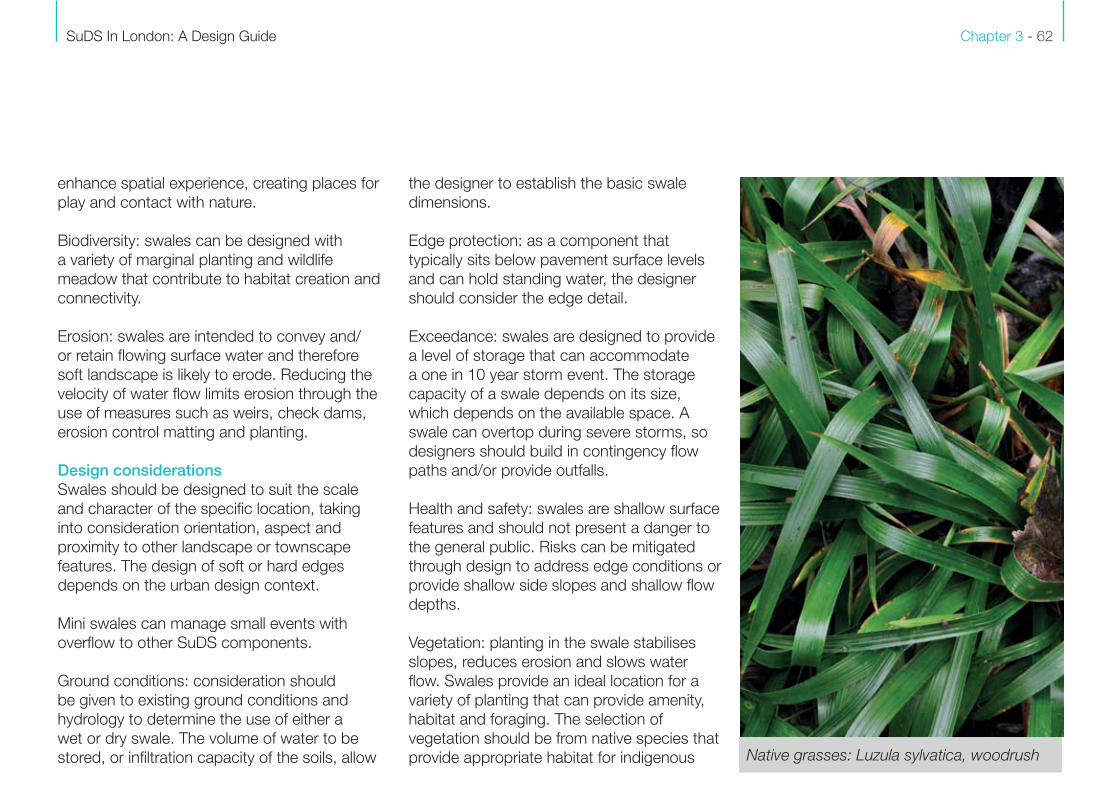
stored, or infiltration capacity of the soils, allow Native grasses: Luzula sylvatica, woodrush

Chapter 3 - 63
species. Where over-the-edge drainage is
required, the grass level should be 25mm
below the edge of the hard standing to be
drained, to ensure effective surface water flow.
Trees: swales can accommodate trees within
their design, provided conditions needed
for growth and the hydrological effects are
considered. Swales should respect the
presence of exisitng trees and ensure root
systems are not compromised. Proposals
should accord with BS 5837:2015 and take
account of tree preservation orders and
conservation area designations.
MaintenanceSwales require routine maintenance to
ensure efficient operation. Different swale
construction and operation affect maintenance
prescriptions.
Useful design guidanceCIRIA C753 The SuDS Manual, Chapter 9.8
and 17
HD 33/06 Surface and Sub-Surface Drainage
Systems For Highways
Dry swale
Image courtesy Robert Bray Associates

SuDS In London: A Design Guide Chapter 3 - 64
Swale - Case study 6
Location Mill Pond Road
London Borough of
Wandsworth
Date 2016
SuDS Components
Bioretention swales
Kerb inlets
Tree trench planting
ObjectivesMill Pond Road is a new road within a
development at Nine Elms. It is constructed
with a central planting bed acting as a swale
to attenuate surface water.
Outcome
The surface water run off is be collected
along bespoke broken kerb units and fed
into the central planting zone where it filters
through to an underground collection and
holding tank before being released slowly into
the mains sewer system. It is anticipated that
there will not be standing water for more than
one or two days following extreme rainfall
events, the plants have been selected to be
tolerant of these conditions. Images courtesy of Camlins
Bioretention swalePlan
Chapter 3 - 65
Rills are small, open-surface water channels
within paved construction. They collect water
directly from hard surfaces and convey water,
at a reduced flow rate, to, from or between
other SuDS components. They come in a
variety of designs to suit the urban landscape
and have formed part of the historic
streetscape environment.
Rills are used as an alternative to piped
drainage, allowing the captured water
to remain at shallow inverts. This allows
easy discharge into other SuDS elements,
compared to buried piped network that may
require deep invert levels.
They can be simple channels, runnels or
ribbed paving, delivering roof water via
downpipes to another feature or a roadside
gutter. Rills can be planted, with rainwater
bringing them to life.
BenefitsRills are an effective way to provide SuDS,
including water treatment if planted, where
space is at a premium.
Amenity: planted rills, interacting with
rainwater, enhance the urban environment.
Conveyance: rills are effective at collecting
and distributing storm water runoff, while
enhancing and demarcating open space.
They can be used in place of pipework and
traditional outfalls.
Filtration: flow-reducing elements, such as
planting, textured paving and other features
provide filtration, treatment and sedimentation
from captured surface water.
Attenuation: rills can attenuate surface water
by providing storage and reducing discharge
rates.
Design considerationsEdge protection: typically sitting below
pavement surface level, rills have hard edges
and can hold standing water. Consider how
pedestrians, cyclists and vehicles will interact
with them, especially at crossing points and in
relation to pedestrian desire lines and vehicle
movement.
Vegetation: rills provide an ideal location for
aquatic or sub aquatic planting for habitat
creation.
Silting: rills can become impaired by silting.
This can be prevented by placing upstream
SuDS components to filter sediment out.
3.7 Rills, runnels and channel systems
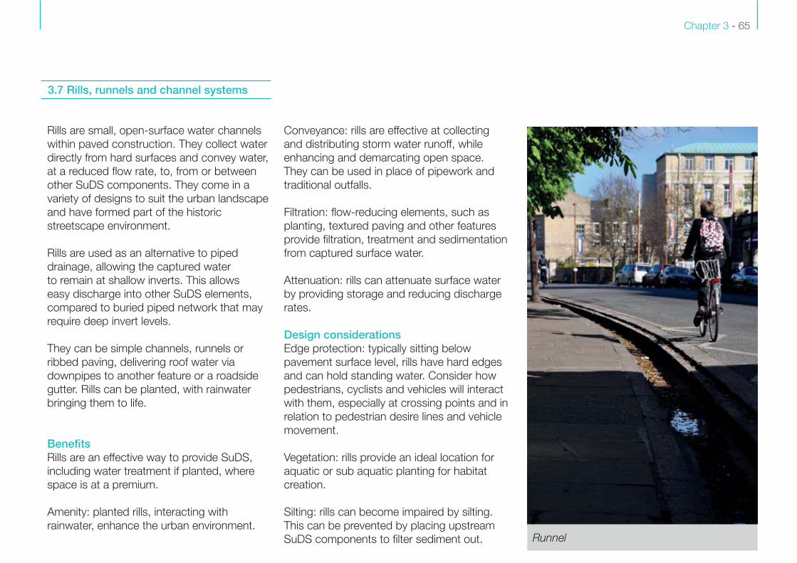
Runnel
SuDS In London: A Design Guide Chapter 3 - 66
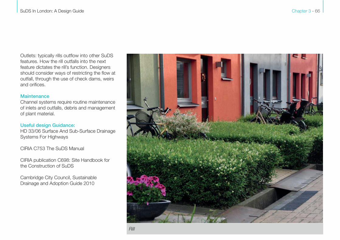
Rill
Outlets: typically rills outflow into other SuDS
features. How the rill outfalls into the next
feature dictates the rill’s function. Designers
should consider ways of restricting the flow at
outfall, through the use of check dams, weirs
and orifices.
MaintenanceChannel systems require routine maintenance
of inlets and outfalls, debris and management
of plant material.
Useful design Guidance:HD 33/06 Surface And Sub-Surface Drainage
Systems For Highways
CIRIA C753 The SuDS Manual
CIRIA publication C698: Site Handbook for
the Construction of SuDS
Cambridge City Council, Sustainable
Drainage and Adoption Guide 2010
Chapter 3 - 67
3.8 Bioretention systems
Bioretention systems, which include rain
gardens, can be incorporated so they do
not need extra land take. They are usually
a planted, soft landscaped low-spot,
positioned to collect, store, filter and reduce
surface runoff from frequent rainfall. As a
surface water management component they
are versatile and can be integrated into public
realm environments through altering street
geometry, creative material choices and
planting.
Inlets, outlets and control structures are used
to control and reduce the water flow rate
through the bioretention system.
Bioretention systems are used to treat
and manage storm events by collecting
local surface water. Water ponds on the
surface, before filtering through vegetation
and growing/filtration media. Here it either
infiltrates or is collected via pipe work leading
to a suitable outfall.
Bioretention tree pits and trenches can be
incorporated into pavements using soils that
intercept, dissipate and cool rainfall runoff.
Bioretention swales are similar to under
drained swales with vegetation tolerant of
likely inundation occurrences and pollutants.
Rain gardens are localised, less engineered
systems. They usually serve a single roof or
small paved area and can create an attractive
addition to the public realm.
BenefitsFiltration: engineered soil or growing media
mixes and filter media can be designed to
enhance bioretention treatment performance.
Attenuation: water can be stored within and
on top of the filtration and growing media,
allowing rainwater to infiltrate over a period of
days.
Conveyance: bioretention features can be
gently sloped or terraced to allow water to be
conveyed at a reduced flow through the use
of check dams, weirs and/or vegetation to a
suitable outfall location.
Amenity and biodiversity: bioretention features
can be integrated in many ways into the
streetscape. Integrating planting has multiple
benefits, enhancing the attractiveness, diversity
and quality of the urban environment, while
meeting local Biodiversity Action Plan targets.
Design considerationsEdge protection: typically, bioretention
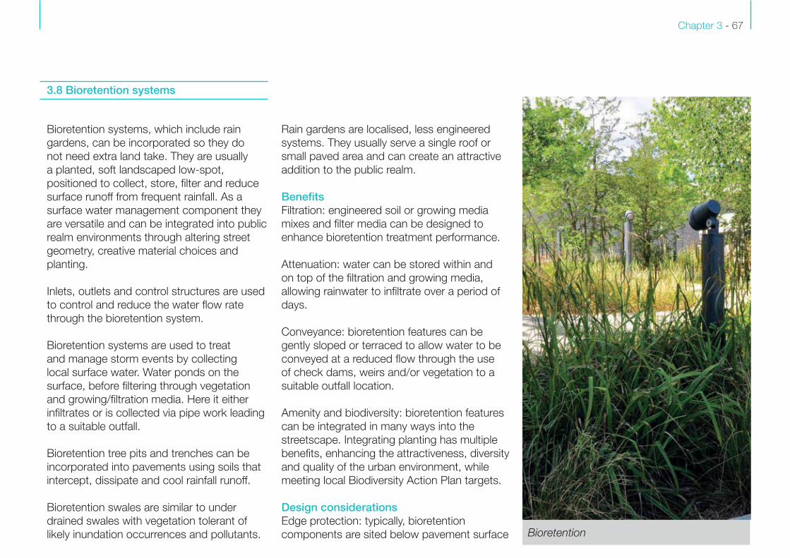
components are sited below pavement surface Bioretention

SuDS In London: A Design Guide Chapter 3 - 68
systems can remediate water contaminants
with the use of filtration mediums, normally
sand-based material with a source of organic
matter to provide nutrients for planting.
Sedimentation: slowing surface water flow
allows fine particles to be removed. Design
should limit excessive sediment accumulation
that could reduce storage volume, filtration and
infiltration rates.
Exceedance: bioretention systems can deal
with only small catchment areas and are likely
to be overwhelmed during heavy storms. The
design should therefore allow for contingency
flow paths and/or provide outfall.
Outfalls: if an outfall is required, consider
the location, particularly the relative level of
potential discharge locations, as bioretention
system outfalls can be deep compared to
conventional drainage.
MaintenanceBioretention systems require routine site
maintenance operations to ensure efficient
operation. Inlets and outfalls require periodic
inspection.
Useful design guidance:CIRIA C753 The SuDS Manual, Chapter 18 Bioretention raingarden: SuDS for Schools
levels and can hold standing water.
It is therefore important that the interface with
pedestrian and vehicular movement is carefully
considered. Bioretention can be profiled in
various ways, with soft edges and gentle side
slopes, or hard edges and vertical sides.
Inlets: inlets may be necessary, especially
when hard edge protection is required. Take
care to ensure bioretention systems are not
subject to excessive erosion at inlet points.
Erosion can be prevented by reducing the
surface water flow velocity via a sediment trap
or a reinforced and textured zone. Protection
grilles should not be used unless the inlet
diameter is greater than 350mm. An outfall
provides overflow when heavy rainfall means
infiltration into the soil is too slow (see below).
Erosion: bioretention systems aim to catch
flowing surface water. Soft landscape may
suffer erosion. Therefore, the feature should be
designed to control the surface water runoff
movement through the use of weirs, check
dams, erosion control matting and planting.
Pollution/contamination: pollution and
contamination sources affecting surface and
ground water may affect planting. Planting
specification should therefore be designed
to meet the specific conditions. Bioretention
Image courtesy of WWT
Chapter 3 - 69
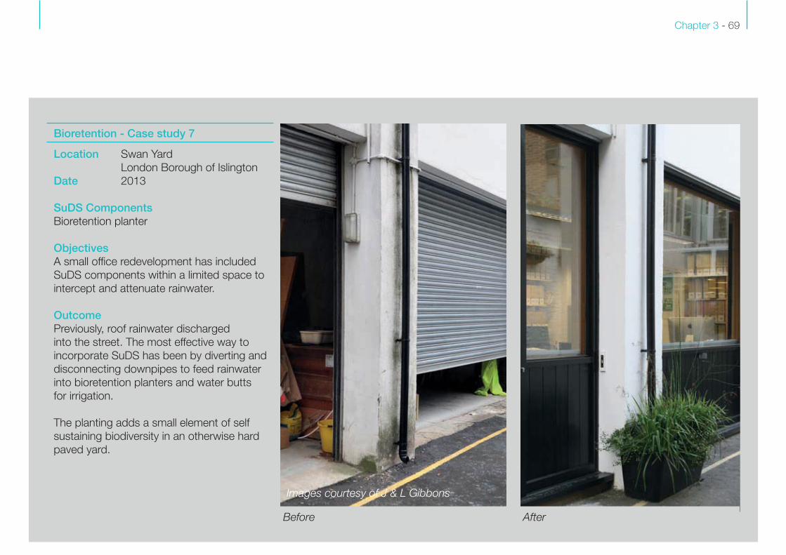
Bioretention - Case study 7
Location Swan Yard
London Borough of Islington
Date 2013
SuDS Components
Bioretention planter
ObjectivesA small office redevelopment has included
SuDS components within a limited space to
intercept and attenuate rainwater.
OutcomePreviously, roof rainwater discharged
into the street. The most effective way to
incorporate SuDS has been by diverting and
disconnecting downpipes to feed rainwater
into bioretention planters and water butts
for irrigation.
The planting adds a small element of self
sustaining biodiversity in an otherwise hard
paved yard.
After Before
Images courtesy of J & L Gibbons
SuDS In London: A Design Guide Chapter 3 - 70
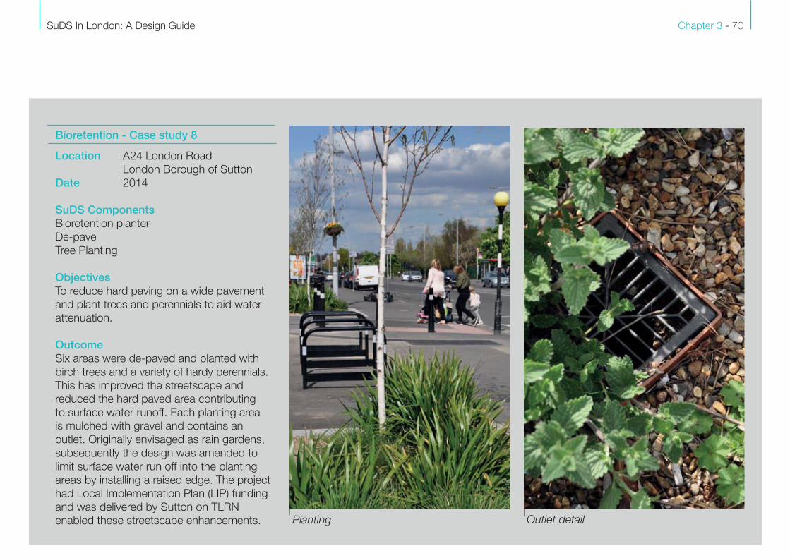
Bioretention - Case study 8
Location A24 London Road
London Borough of Sutton
Date 2014
SuDS Components
Bioretention planter
De-pave
Tree Planting
ObjectivesTo reduce hard paving on a wide pavement
and plant trees and perennials to aid water
attenuation.
Outcome
Six areas were de-paved and planted with
birch trees and a variety of hardy perennials.
This has improved the streetscape and
reduced the hard paved area contributing
to surface water runoff. Each planting area
is mulched with gravel and contains an
outlet. Originally envisaged as rain gardens,
subsequently the design was amended to
limit surface water run off into the planting
areas by installing a raised edge. The project
had Local Implementation Plan (LIP) funding
and was delivered by Sutton on TLRN
enabled these streetscape enhancements. Planting Outlet detail

Chapter 3 - 71
Bioretention - Case study 9
Location Granton Road
London Borough of Lambeth
Date 2015
SuDS Components
Rain planters
ObjectivesTrial project: The local school needed to
tackle illegal parking on the yellow zig-zags,
traffic congestion and conflict as parents
queued in their cars outside the school.
Outcome
A six-month trial saw the installation of timber
planters. During term-time the planters were
maintained by the school children, although
this proved problematic over the longer
summer break. Traffic was monitored before,
during and after the trial.
A permanent solution will now seek to
incorporate in-ground SuDS, that will address
the seasonal issue and provide a learning
facility for the school.
The results: 1 year on44%*
132 cars
72 cars
cars travelling at 10-15mph*
What the parents think
86% of parents surveyed agree it is safer now
94% of parents surveyed would like the planters to be made permanent**
*between the hours of 7.30-9am in term time
**we surveyed 53 parents, 11% of the school roll
Timber planters as a trial solution for SuDS Results of trial
Images courtesy of Sustrans
SuDS In London: A Design Guide Chapter 3 - 72
Trees in the hard landscape, parks and
gardens and to some extent streets
contribute significantly to London’s ‘urban
forest’. In terms of SuDS, they perform
through attenuation, interception and
soil permeability. Trees provide multiple
ecosystem services and mitigation from the
effects of climate change, including cooling
and improving air quality. Trees greatly
benefit the urban environment in terms of
heritage, amenity, and biodiversity. They
help to reinforce a sense of place and also
complement traffic calming measures.
BenefitsAttenuation: tree pits provide storage of
storm water runoff through the use of
structural soils or proprietary crate systems.
Filtration: soils and geotextiles that make up
the construction of tree pits remove silts and
particulates that may be present in runoff
water. Through ‘phytoremediation’, trees
absorb trace amounts of harmful chemicals,
including metals, hydrocarbons and solvents,
where they are transformed into less harmful
substances or used as nutrients.
Interception: trees intercept rainfall and
store it. This reduces the amount of water
reaching the ground, thereby reducing
volume of runoff.
Infiltration: soil infiltration rates are improved
due to root growth that also enhances soil
biodiversity.
Water reduction: through a process called
‘transpiration’, trees draw water from the
ground through root systems to their leaves,
where it is lost through evaporation. This
effects cooling.
Amenity: street trees contribute to the capital,
both visually and environmentally, and form an
important component of London’s streetscene.
London’s climate allows for a wide diversity
of native and exotic species. For instance,
London’s urban forest removes over 2,000
tons of pollution/ha/year and stores 2.3
million tonnes of carbon per annum . Tree-
lined streets make cycling and walking more
pleasant, which is directly related to the health
and wellbeing of Londoners.
Biodiversity: trees constitute the largest single
element of biomass in the city, providing
significant biodiversity value. Trees and
woodlands provide food, habitat and shelter
for birds, invertebrates and other species,
some of which are subject to legal protection.
For example, a large species tree, such as an
oak, can host hundreds of different animals,
plants and fungi, with long-term benefit to
pollinators and the urban ecology .
Design considerationsExisting trees: existing trees should be
retained wherever possible. Proposals should
accord with BS5837:2015 and take account
of tree preservation orders and conservation
area designations.
Available space: tree pits require space below
ground to successfully accommodate long-
term root growth. Tree pits and trenches
(connected pits) should provide adequate soil
volume, water and gaseous exchange to the
root system. The location of below ground
services and drainage should be identified to
ensure root zones, utilities and other below
ground infrastructure are all coordinated.
Protection for both long-term root growth and
below ground infrastructure can be provided
with root barriers. Guidance on delivering
trees in hard landscapes is provided by Trees
and Design Action Group (TDAG).
3.9 Trees

Chapter 3 - 73
Tree specification: tree species and diversity,
provenance, mature size, clear stem height,
root preparation and procurement should be
carefully considered. For the benefits of large
species trees in urban environments see CIRIA
C712. Tree specification and soils performance
criteria should be developed in parallel as an
integral part of SuDS component design and
long-term vision.
Catchment: a single tree can intercept the
rainfall equivalent to the area draining into a
single road gully. However, by combining trees
with other SuDS components, the volume
of rainwater interception and attenuation in
the catchment can be significantly increased.
The London iTree eco project, for instance,
demonstrated that the combined canopy cover
of London produces an avoided runoff of some
3.4 million cubic metres per year.
Soils: where possible, trees should be
established within soft landscape areas,
rather than confine rooting zones to restricted
trenches in hard landscape.
Where tree planting is incorporated into
hard landscape, the use of load-bearing tree
planting systems may be necessary. New
and retrofit SuDS schemes will require these
systems, which may categorise the street as
a zone of ‘special engineering difficulty’. There
are several systems available for planting in
hard landscape, including:
• Cell systems
• Urban tree soil
• Raft systems
• Structural growing media
Soil depths: the overall depth of soil should
be appropriate for the tree species. Excessive
topsoil depth increases the risk of anaerobic
conditions (oxygen deficiency). Topsoil should
therefore only be used within the upper part
of the soil profile, with suitable subsoil in the
lower layer. The exact depth permissible will
be dependent on soil conditions, the tree
specification and the type of load-bearing
system (see soils: Chapter 2).
Infiltration rates: the rate of infiltration of a tree
pit dictates the size of the tree pit required for
water storage means. The construction of the
pit can be altered accordingly.
Pollution/contamination: pollution and
contamination sources affecting surface and
ground water influences tree growth. Certain
species are more susceptible than others, and
species selection should be specific to each
site and SuDS scheme. Street trees: Biodiversity

SuDS In London: A Design Guide Chapter 3 - 74
Tree lined streets: Multiple ecosystem services
Chapter 3 - 75
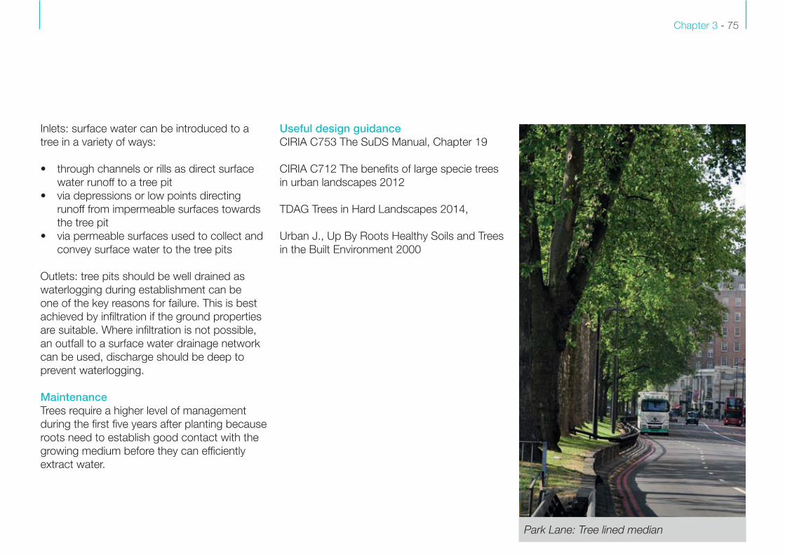
Park Lane: Tree lined median
Inlets: surface water can be introduced to a
tree in a variety of ways:
• through channels or rills as direct surface
water runoff to a tree pit
• via depressions or low points directing
runoff from impermeable surfaces towards
the tree pit
• via permeable surfaces used to collect and
convey surface water to the tree pits
Outlets: tree pits should be well drained as
waterlogging during establishment can be
one of the key reasons for failure. This is best
achieved by infiltration if the ground properties
are suitable. Where infiltration is not possible,
an outfall to a surface water drainage network
can be used, discharge should be deep to
prevent waterlogging.
MaintenanceTrees require a higher level of management
during the first five years after planting because
roots need to establish good contact with the
growing medium before they can efficiently
extract water.
Useful design guidanceCIRIA C753 The SuDS Manual, Chapter 19
CIRIA C712 The benefits of large specie trees
in urban landscapes 2012
TDAG Trees in Hard Landscapes 2014,
Urban J., Up By Roots Healthy Soils and Trees
in the Built Environment 2000
SuDS In London: A Design Guide Chapter 3 - 76
Trees - Case study 10
Location Hyllie Plaza
Malmo, Sweden
Date 2010
SuDS Components
Tree trench attenuation
Tree planting
ObjectivesTo establish a ‘forest’ in the plaza using a
species of beech typical of the area with
fully integrated SuDS. The forest contributes
to regional identity whilst intercepting and
attenuating rainwater.
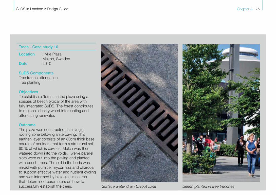
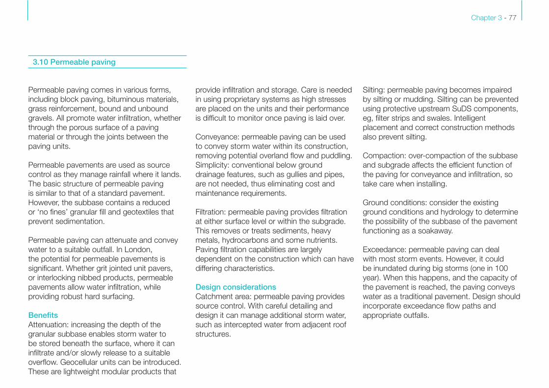
OutcomeThe plaza was constructed as a single
rooting zone below granite paving. This
earthen layer consists of an 80cm thick base
course of boulders that form a structural soil,
60 % of which is cavities. Mulch was then
watered down into the voids. Twelve parallel
slots were cut into the paving and planted
with beech trees. The soil in the beds was
mixed with pumice, mycorrhiza and charcoal
to support effective water and nutrient cycling
and was informed by biological research
that determined parameters on how to
successfully establish the trees. Surface water drain to root zone Beech planted in tree trenches
Chapter 3 - 77
3.10 Permeable paving
Permeable paving comes in various forms,
including block paving, bituminous materials,
grass reinforcement, bound and unbound
gravels. All promote water infiltration, whether
through the porous surface of a paving
material or through the joints between the
paving units.
Permeable pavements are used as source
control as they manage rainfall where it lands.
The basic structure of permeable paving
is similar to that of a standard pavement.
However, the subbase contains a reduced
or ‘no fines’ granular fill and geotextiles that
prevent sedimentation.
Permeable paving can attenuate and convey
water to a suitable outfall. In London,
the potential for permeable pavements is
significant. Whether grit jointed unit pavers,
or interlocking nibbed products, permeable
pavements allow water infiltration, while
providing robust hard surfacing.
BenefitsAttenuation: increasing the depth of the
granular subbase enables storm water to
be stored beneath the surface, where it can
infiltrate and/or slowly release to a suitable
overflow. Geocellular units can be introduced.
These are lightweight modular products that
provide infiltration and storage. Care is needed
in using proprietary systems as high stresses
are placed on the units and their performance
is difficult to monitor once paving is laid over.
Conveyance: permeable paving can be used
to convey storm water within its construction,
removing potential overland flow and puddling.
Simplicity: conventional below ground
drainage features, such as gullies and pipes,
are not needed, thus eliminating cost and
maintenance requirements.
Filtration: permeable paving provides filtration
at either surface level or within the subgrade.
This removes or treats sediments, heavy
metals, hydrocarbons and some nutrients.
Paving filtration capabilities are largely
dependent on the construction which can have
differing characteristics.
Design considerationsCatchment area: permeable paving provides
source control. With careful detailing and
design it can manage additional storm water,
such as intercepted water from adjacent roof
structures.
Silting: permeable paving becomes impaired
by silting or mudding. Silting can be prevented
using protective upstream SuDS components,
eg, filter strips and swales. Intelligent
placement and correct construction methods
also prevent silting.
Compaction: over-compaction of the subbase
and subgrade affects the efficient function of
the paving for conveyance and infiltration, so
take care when installing.
Ground conditions: consider the existing
ground conditions and hydrology to determine
the possibility of the subbase of the pavement
functioning as a soakaway.
Exceedance: permeable paving can deal
with most storm events. However, it could
be inundated during big storms (one in 100
year). When this happens, and the capacity of
the pavement is reached, the paving conveys
water as a traditional pavement. Design should
incorporate exceedance flow paths and
appropriate outfalls.
SuDS In London: A Design Guide Chapter 3 - 78
MaintenanceMaintenance requirements are no more
onerous for permeable paving than for
traditional impermeable surfaces. The
removal of conventional below-ground
drainage features, such as gullies and
pipework, eliminates associated maintenance
requirements.
Over time, detritus collects in the upper part
of the joint material and surfaces pores.
This build-up can affect infiltration capability.
Even so, studies have shown that long-term
infiltration capability generally exceeds UK
hydrological requirements.
The maintenance regime of paving is largely
dependent on the construction of the surface
course. Brushing and joint material renewal is
required, the frequency of which is determined
by local conditions, and is no more than
required of traditional surfacing.
Weeds will need to be removed from joints,
unless wildflower establishment is part of the
design concept. Maintenance regimes related
to design aspiration and SuDS performance
need to be clearly established from the
outset, with related community interpretation if
departing from perceived norms.
Useful design guidanceCIRIA C753 The SuDS Manual, Chapter 20
Interpave, The Precast Concrete Paving and
Kerb Association, Information found at: www.
paving.org.uk
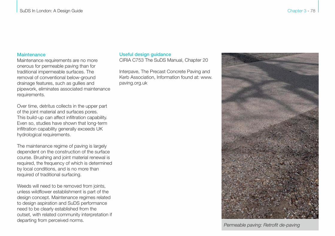
Permeable paving: Retrofit de-paving
Chapter 3 - 79
Permeable paving - Case study 11
Location Mendora Road
London Borough of
Hammersmith & Fulham
Date 2016 (under construction)
SuDS Components
Permeable paving retrofit
ObjectivesThis Thames Water Utilities Limited (TWUL)
project aims to trial the retrofit of SuDS within
the highway with a focus on their flood risk
benefits. Three streets were selected for the
trial as part of the Counters Creek SuDS
Retrofit Pilot Schemes
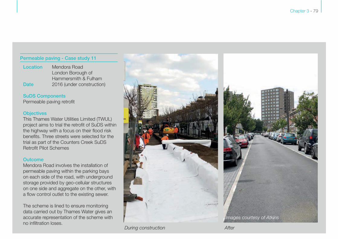
Outcome
Mendora Road involves the installation of
permeable paving within the parking bays
on each side of the road, with underground
storage provided by geo-cellular structures
on one side and aggregate on the other, with
a flow control outlet to the existing sewer.
The scheme is lined to ensure monitoring
data carried out by Thames Water gives an
accurate representation of the scheme with
no infiltration loses.
Image courtesy of Atkins Image courtesy of Atkins
FIND H
I-RES
Images courtesy of Atkins
During construction After
SuDS In London: A Design Guide Chapter 3 - 80
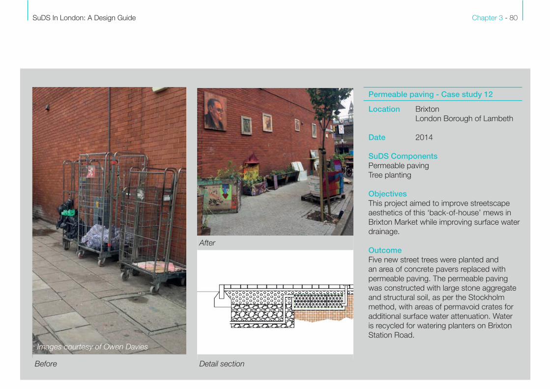
Permeable paving - Case study 12
Location Brixton
London Borough of Lambeth
Date 2014
SuDS Components
Permeable paving
Tree planting
ObjectivesThis project aimed to improve streetscape
aesthetics of this ‘back-of-house’ mews in
Brixton Market while improving surface water
drainage.
Outcome
Five new street trees were planted and
an area of concrete pavers replaced with
permeable paving. The permeable paving
was constructed with large stone aggregate
and structural soil, as per the Stockholm
method, with areas of permavoid crates for
additional surface water attenuation. Water
is recycled for watering planters on Brixton
Station Road.
Detail section
After
Images courtesy of Owen Davies
Before
Chapter 3 - 81
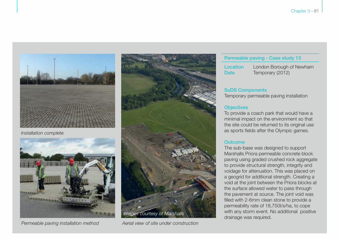
Permeable paving - Case study 13
Location London Borough of Newham
Date Temporary (2012)
SuDS Components
Temporary permeable paving installation
ObjectivesTo provide a coach park that would have a
minimal impact on the environment so that
the site could be returned to its original use
as sports fields after the Olympic games.
Outcome
The sub-base was designed to support
Marshalls Priora permeable concrete block
paving using graded crushed rock aggregate
to provide structural strength, integrity and
voidage for attenuation. This was placed on
a geogrid for additional strength. Creating a
void at the joint between the Priora blocks at
the surface allowed water to pass through
the pavement at source. The joint void was
filled with 2-6mm clean stone to provide a
permeability rate of 18,750l/s/ha, to cope
with any storm event. No additional positive
drainage was required.Image courtesy of Marshalls Images courtesy of MarshallsImImImImImmmImIImmImmImImmImmmmmmagagagagagagagagagagaggggagggagagaggggaaaagaaaggge eeeeee ee eeeee cocococococococococococococococcooourururururururururururuuruuruurttetetettetetetettettetettteteettesysysysysysyysysysysysy ooooooooooooooff fff ff f ffffff MaMaMaMaMaMaMaMaMaaMaMaMMaMMaaMMarsrsrsrsrsrsrsrsrsrsrsr hahahahhahaahahahhahahhahaaaahah lllllllllllllllllllllllllllssssssssssssss
Installation complete
Permeable paving installation method Aerial view of site under construction
SuDS In London: A Design Guide Chapter 3 - 82
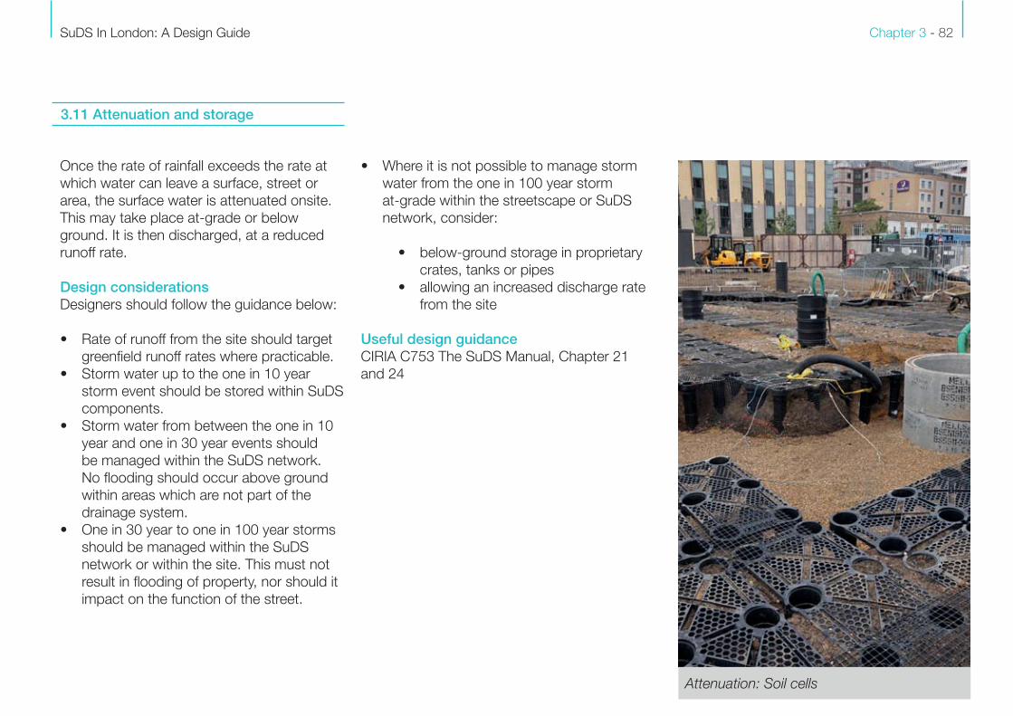
Once the rate of rainfall exceeds the rate at
which water can leave a surface, street or
area, the surface water is attenuated onsite.
This may take place at-grade or below
ground. It is then discharged, at a reduced
runoff rate.
Design considerationsDesigners should follow the guidance below:
• Rate of runoff from the site should target
greenfield runoff rates where practicable.
• Storm water up to the one in 10 year
storm event should be stored within SuDS
components.
• Storm water from between the one in 10
year and one in 30 year events should
be managed within the SuDS network.
No flooding should occur above ground
within areas which are not part of the
drainage system.
• One in 30 year to one in 100 year storms
should be managed within the SuDS
network or within the site. This must not
result in flooding of property, nor should it
impact on the function of the street.
3.11 Attenuation and storage
• Where it is not possible to manage storm
water from the one in 100 year storm
at-grade within the streetscape or SuDS
network, consider:
• below-ground storage in proprietary
crates, tanks or pipes
• allowing an increased discharge rate
from the site
Useful design guidance CIRIA C753 The SuDS Manual, Chapter 21
and 24
Attenuation: Soil cells
Chapter 3 - 83
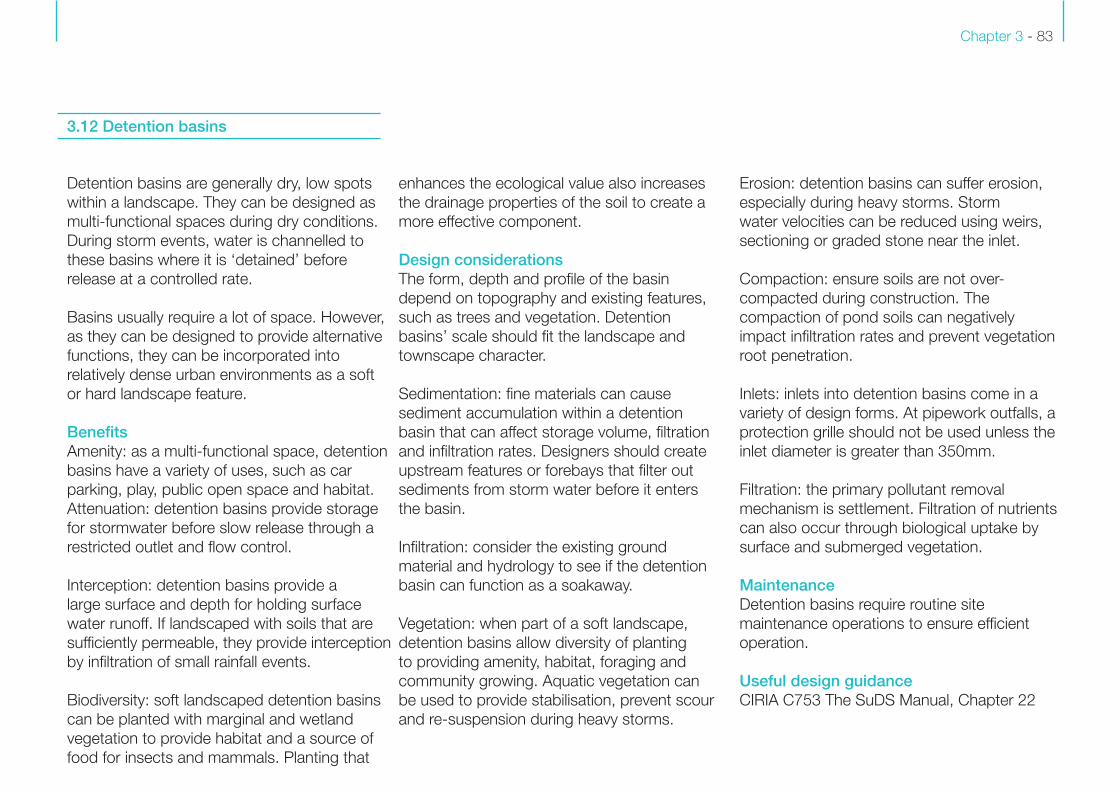
3.12 Detention basins
Detention basins are generally dry, low spots
within a landscape. They can be designed as
multi-functional spaces during dry conditions.
During storm events, water is channelled to
these basins where it is ‘detained’ before
release at a controlled rate.
Basins usually require a lot of space. However,
as they can be designed to provide alternative
functions, they can be incorporated into
relatively dense urban environments as a soft
or hard landscape feature.
BenefitsAmenity: as a multi-functional space, detention
basins have a variety of uses, such as car
parking, play, public open space and habitat.
Attenuation: detention basins provide storage
for stormwater before slow release through a
restricted outlet and flow control.
Interception: detention basins provide a
large surface and depth for holding surface
water runoff. If landscaped with soils that are
sufficiently permeable, they provide interception
by infiltration of small rainfall events.
Biodiversity: soft landscaped detention basins
can be planted with marginal and wetland
vegetation to provide habitat and a source of
food for insects and mammals. Planting that
enhances the ecological value also increases
the drainage properties of the soil to create a
more effective component.
Design considerationsThe form, depth and profile of the basin
depend on topography and existing features,
such as trees and vegetation. Detention
basins’ scale should fit the landscape and
townscape character.
Sedimentation: fine materials can cause
sediment accumulation within a detention
basin that can affect storage volume, filtration
and infiltration rates. Designers should create
upstream features or forebays that filter out
sediments from storm water before it enters
the basin.
Infiltration: consider the existing ground
material and hydrology to see if the detention
basin can function as a soakaway.
Vegetation: when part of a soft landscape,
detention basins allow diversity of planting
to providing amenity, habitat, foraging and
community growing. Aquatic vegetation can
be used to provide stabilisation, prevent scour
and re-suspension during heavy storms.
Erosion: detention basins can suffer erosion,
especially during heavy storms. Storm
water velocities can be reduced using weirs,
sectioning or graded stone near the inlet.
Compaction: ensure soils are not over-
compacted during construction. The
compaction of pond soils can negatively
impact infiltration rates and prevent vegetation
root penetration.
Inlets: inlets into detention basins come in a
variety of design forms. At pipework outfalls, a
protection grille should not be used unless the
inlet diameter is greater than 350mm.
Filtration: the primary pollutant removal
mechanism is settlement. Filtration of nutrients
can also occur through biological uptake by
surface and submerged vegetation.
MaintenanceDetention basins require routine site
maintenance operations to ensure efficient
operation.
Useful design guidanceCIRIA C753 The SuDS Manual, Chapter 22
SuDS In London: A Design Guide Chapter 3 - 84
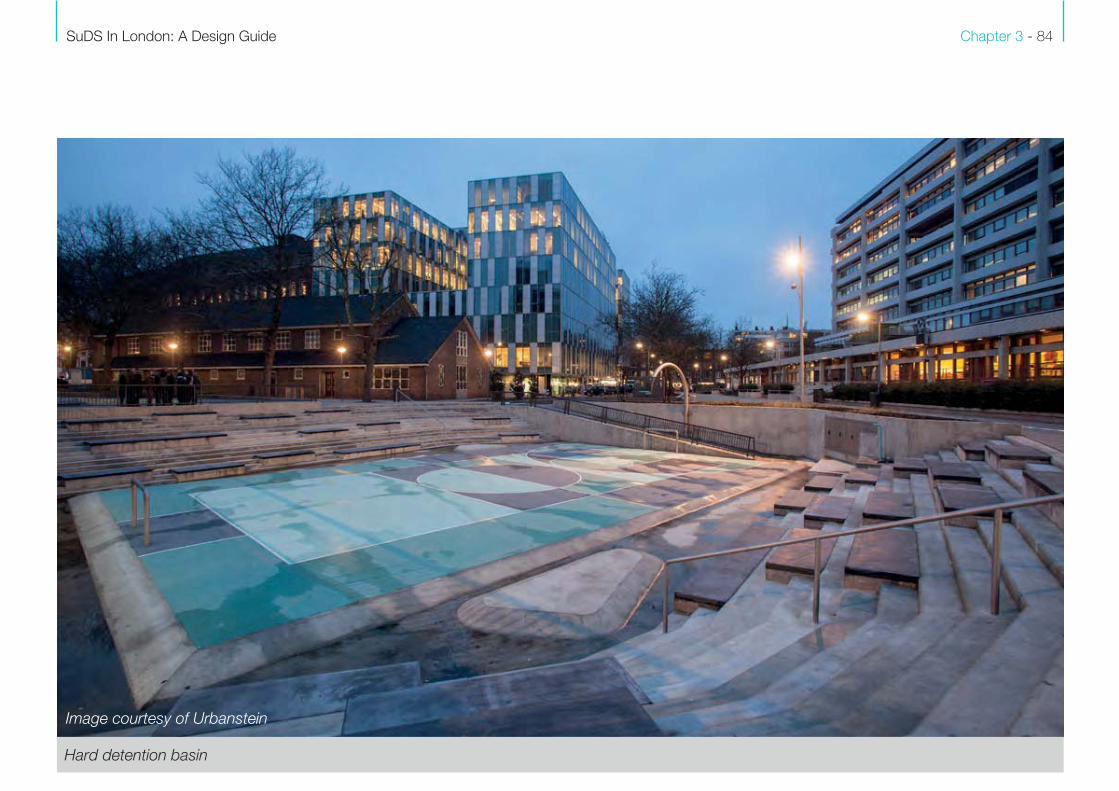
Hard detention basin
Image courtesy of Urbanstein
Chapter 3 - 85
Ponds and wetlands are referred to as
‘catchment’ measures because they are
generally used where runoff cannot be
managed at source. Such features are
viable where there is lots of space available;
however, small scale integration is also
possible.
Ponds are not usually efficient in terms of
collection and conveyance, and therefore
are usually located towards the end of the
management train, where the demand for
storage is greatest, with suitable upstream
pre-treatment. They provide high value
wildlife and amenity benefits to an area and
effectively treat polluted water naturally.
Ponds and wetlands hold a permanent pool
of water, even in dry conditions. The depth
of water increases during storm events,
attenuating and treating surface water runoff
before outfall at a controlled rate to a suitable
discharge point.
BenefitsAttenuation: ponds and wetlands store a
lot of storm water. The more water there is,
the more time there is for sedimentation,
biodegradation and biological uptake.
Filtration: through the use of engineered
soil mixes and additives, filter media can be
created to enhance bioretention treatment
performance. Designs can include submerged
anaerobic zones to promote nutrient
renewal. Reedbeds are highly effective at
bioremediation.
Amenity: permanent water features, such as
ponds and wetlands, offer important aesthetic
and amenity benefits to development.
Integrating an aquatic bench, to create a
shallow zone for wetland planting, increases
aesthetic value and the potential for biological
filtration and habitat. Ponds can incorporate
features such as islands and shallows that
allow greater access and interaction.
Biodiversity: design features such as shallow
and convoluted edges, uneven surfaces,
woodlands, tussock grass areas and dead
wood piles increase habitat diversity. These
can provide shelter, food, foraging and
breeding opportunities for a range of urban
wildlife.
Design considerationsSedimentation: fine materials cause sediment
accumulation within ponds and wetlands,
reducing storage volume, filtration and
infiltration rates. Mitigation measures can
be implemented upstream or by installing a
sedimentation area within the catchment.
Vegetation: ponds and wetlands are ideal
spots for planting, which can provide amenity
and habitat. Prioritise native species that are
resilient to local conditions. Aquatic vegetation
can provide stabilisation, prevent scour and re-
suspension during heavy storms.
Edge protection: ponds and wetlands hold
standing water so nearby motorists, cyclists
and pedestrians need to be considered. Trees,
woodland, planting, benches or other physical
obstructions can provide natural protection.
Erosion: ponds and wetlands are susceptible
to erosion, especially during heavy storms.
Storm water velocities can be slowed through
planting and low-tech bio-engineering
sympathetic to the character of the SuDS
component.
3.13 Ponds and wetlands
SuDS In London: A Design Guide Chapter 3 - 86
Compaction: ensure soils are not compacted
during construction. Compaction of the pond
soils can reduce infiltration rates, and prevent
vegetation root penetration and establishment.
Outlets: a non-clogging, variable flow rate
control structure, together with an emergency
overflow should be incorporated. This might be
a protected orifice, combined with an overflow
channel protected with a weir.
Inlets: ensure excessive erosion at inlet points
does not occur. Where pipework outfalls a
protection grille should not be used unless the
inlet diameter is greater than 350mm.
Filtration: ponds and wetlands treat surface
water runoff by sedimentation that occurs
during the time water remains in the pond.
Filtration of nutrients can also occur through
biological uptake by surface, submerged and
aquatic vegetation, particularly reedbeds.
MaintenanceRoutine inspection and maintenance is
important to ensure the efficient operation
of ponds and wetlands. Maintenance
regimes over and above routine on-site pond
maintenance include water quality monitoring
and control of algal bloom.
Useful design guidanceCIRIA C753 The SuDS Manual, Chapter 23
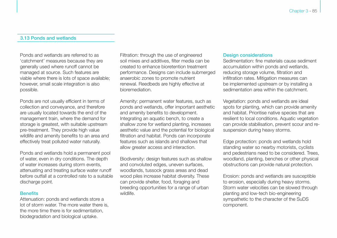
Pond, high in biodiversity and aesthetic value
Chapter 3 - 87
Life-cycle management and maintenance
are key considerations of SuDS schemes.
If well designed, most SuDS components
function without additional inspection over
and above routine site maintenance of the
public realm. Principles of good management
and maintenance to ensure SuDS system
continues to function long-term are:
1. Design from the outset with long-term
management and maintenance in mind.
Ensure that site or street management
can deal with most SuDS requirements;
SuDS components can be managed by
operatives without specialist horticultural
skill; all SuDS minimise the need for
component replacement and ease of
inspection.
2. Planting specified should be resilient
enough to thrive in drought and flood
conditions.
3. Ensure the soil specification and plant
species selection meet the specific
demands of the SuDS system, site
characteristics and geotechnical
conditions
4. The Highway Authority and TfL Street
Manager must play a key role in informing
design decisions; tailor schemes to
suit service level and management/
maintenance requirements, to ensure
successful SuDS delivery and sustainability.
5. Ensure compliance with TfL Green Estate
Management Plan (2013) that guides the
management of the TLRN Green Estate,
and local authority asset management
plans and maintenance procedures and
prescriptions.
Operational constraints on management
and maintenance vary, principally between
schemes on the TLRN and those associated
with borough maintained streets. Crucial
to successful delivery is close collaboration
with the Highways Authority throughout the
feasibility and design process.
3.14 Management and maintenance
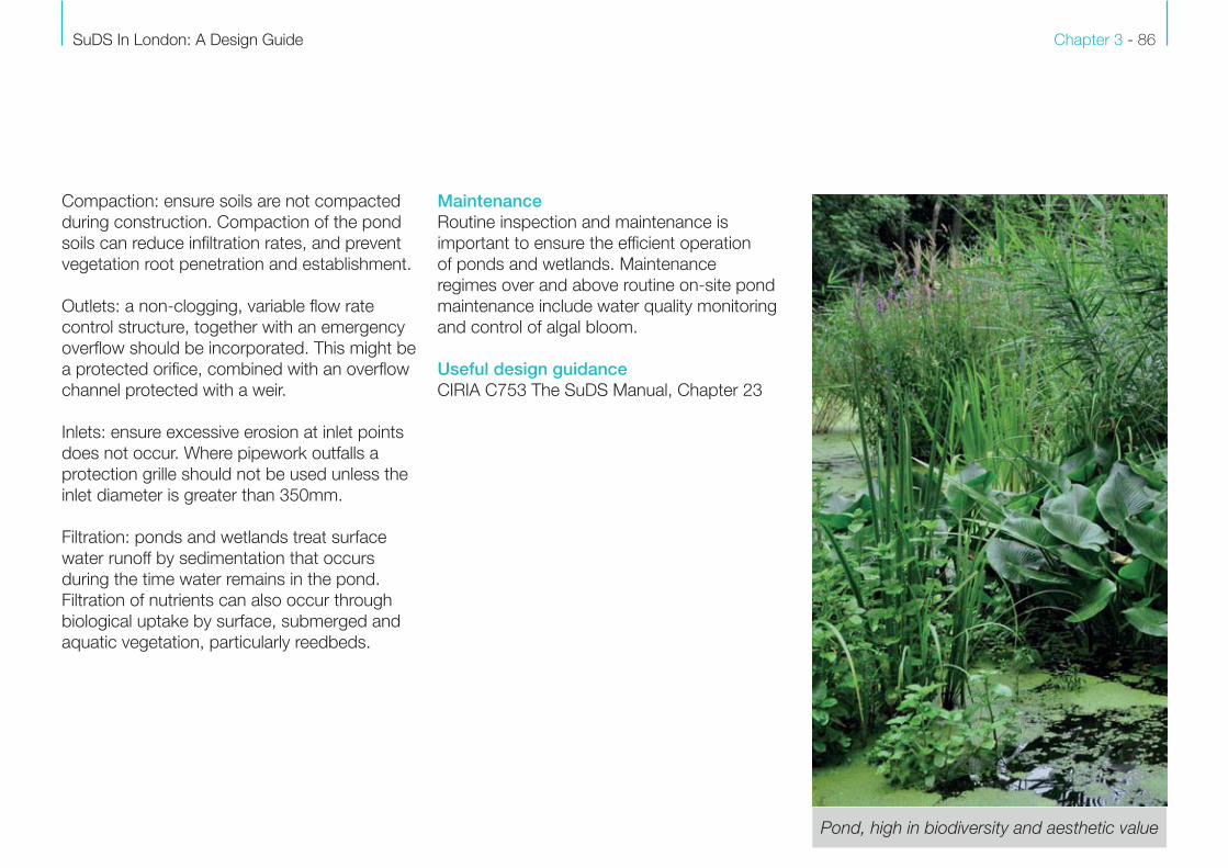
Weir, providing ease of maintenance
Image courtesy Robert Bray Associates

![INDEX [controlwell.com]controlwell.com/cataloguepdf/cableglands.pdf · 4 Size Cat. No. Grey BS-01 BS-02 BS-03 BS-04 BS-05 BS-06 BS-07 BS-08 BS-09 BS-10 Clamping Range (mm) 3 - 6.5](https://static.documents.pub/doc/80x56/5aa168cf7f8b9a07758b8558/index-4-size-cat-no-grey-bs-01-bs-02-bs-03-bs-04-bs-05-bs-06-bs-07-bs-08-bs-09.jpg)


![[DIRECTION MATTERS]dost mohammad etc. aura & co. versus the state of jharkhand i.a. no. 13252/2020- application for amendment in cause title ia no. 13252/2020 - amendment in cause](https://static.documents.pub/doc/80x56/5e98716328dbe2753d4c14e6/direction-matters-dost-mohammad-etc-aura-co-versus-the-state-of-jharkhand.jpg)
