-1- 300 HYDRO-TOWER 300 IN-WALL TANK INSTALLATION INSTRUCTIONS K-4178T/K-4177T/K-8857T · · · · Read installation guide in illustration and word file carefully, and install the tank according to instructions in the guide to avoid product damage and installation inconvenience caused by inappropriate operation. All data contained is based upon the last product information available at the time of publication. Kohler Company reserves the right to implement changes of product characteristics, packaging and availability at any time without further notice. Do not apply erosive cleanser and solvent in the tank, which will damage tank spares and result in leakage in the tank. Kohler will not be responsible for any damage related to above mentioned cleanser or solvent. Do not apply spares that are not provided by Kohler, and please note that glass adhesive tape shall not be applied to the installation of Kohler spares. Kohler will not be responsible for any damage related to installation with spares not provided by Kohler. · Water temperature must not exceed 27 C. o · · · · · o C 27 300 ( ) .....................K-4178T ............................................K-4177T ............................................K-8857T Ordering Information HYDRO-TOWER 300 In-Wall Tank(With Frame) .......K-4178T DROPLET In-Wall Tank Faceplate .............................K-4177T BEVEL In-Wall Tank Faceplate ..................................K-8857T , 2012 Copyright Kohler China Ltd., 2012 · · · · Function Explanation · · · · Anti flow-backwards Adjustment of inlet water level Adjustment of flushing volume Single/double gear flushing · · · · Installation of in-wall tank is much easier and nice-looking comparative to that of traditional tank. Meanwhile, the space layout will be more reasonable due to the application of in-wall tank pipes and connectors. The most remarkable advantage of in-wall tank is that the installation will never be limited to certain area, and can be installed wherever as you wish, which will make the bathroom layout more reasonable and nice-looking, and make good use of every inch of the bathroom space. Design And Installation Concept Of In-wall Tank · · · · · K-8752T/8750T / K-19045W/19045T / K-18609T/19720T / K-19080/19080T / K-19957W/19957T / Wall-hung Toilet That Matches The Tank · · · · · K-8752T/8750T ODEON Wall-hung P-Trap Toilet/Bowl K-19045W/19045T ESCALE Wall-hung P-Trap Toilet/Bowl K-18609T/19720T VIA Wall-hung P-Trap Toilet/Bowl K-19080/19080T PRESQU'ILE Wall-hung P-Trap Toilet/Bowl K-19957W/19957T OVE Wall-hung P-Trap Toilet/Bowl BEFORE YOU BEGIN BEFORE YOU BEGIN 1148318-T01-B
Transcript
-1-
300 HYDRO-TOWER 300
IN-WALL TANK
INSTALLATION INSTRUCTIONS
K-4178T/K-4177T/K-8857T
�
�
�
�
Read installation guide in illustration and word filecarefully, and install the tank according to instructions inthe guide to avoid product damage and installationinconvenience caused by inappropriate operation.All data contained is based upon the last productinformation available at the time of publication. KohlerCompany reserves the right to implement changes ofproduct characteristics, packaging and availability at anytime without further notice.Do not apply erosive cleanser and solvent in the tank,which will damage tank spares and result in leakage in thetank. Kohler will not be responsible for any damagerelated to above mentioned cleanser or solvent.Do not apply spares that are not provided by Kohler, andplease note that glass adhesive tape shall not be appliedto the installation of Kohler spares. Kohler will not beresponsible for any damage related to installation withspares not provided by Kohler.
HYDRO-TOWER 300 In-Wall Tank(With Frame) .......K-4178TDROPLET In-Wall Tank Faceplate.............................K-4177TBEVEL In-Wall Tank Faceplate ..................................K-8857T
, 2012
Copyright Kohler China Ltd., 2012
�
�
�
�
Function Explanation
�
�
�
�
Anti flow-backwardsAdjustment of inlet water levelAdjustment of flushing volumeSingle/double gear flushing
�
�
�
�
Installation of in-wall tank is much easier and nice-lookingcomparative to that of traditional tank. Meanwhile, thespace layout will be more reasonable due to theapplication of in-wall tank pipes and connectors.The most remarkable advantage of in-wall tank is that theinstallation will never be limited to certain area, and canbe installed wherever as you wish, which will make thebathroom layout more reasonable and nice-looking, andmake good use of every inch of the bathroom space.
Design And Installation Concept Of In-wall Tank
�
�
�
�
�
K-8752T/8750T /K-19045W/19045T /
K-18609T/19720T /K-19080/19080T /
K-19957W/19957T /
Wall-hung Toilet That Matches The Tank
�
�
�
�
�
K-8752T/8750T ODEON Wall-hung P-Trap Toilet/BowlK-19045W/19045T ESCALE Wall-hung P-TrapToilet/BowlK-18609T/19720T VIA Wall-hung P-Trap Toilet/BowlK-19080/19080T PRESQU'ILE Wall-hung P-TrapToilet/BowlK-19957W/19957T OVE Wall-hung P-Trap Toilet/Bowl
BEFORE YOU BEGINBEFORE YOU BEGIN
1148318-T01-B
ROUGHING-IN
UNIT: mm
-2-
�
�
�
�
�
�
�
�
Advantages Of In-wall Tank
�
�
�
�
�
�
�
�
Made ofmacromolecular materials thatprevents corrisonand leaking.
Will not affect the structure of the wall and providesexcellent sound insulation.Easy installation and time efficient.
..
Clean, garbage free, and space .
Advanced water tank fitting, which makes possible theadjustment of the water discharge and double flush.
Extra-thin shell of the tank helps to save a lot of spaceand fit for any walls.
Do notneed toprepare any other spare partsEasymaintenance and servicing
saving
Kohler reserves the right to change marked dimensions without prior notice.
Reference Value
478 2
215
150
705 2
35 2
100 2
180 1
230 1
1110 2
88 2
88~128
13~62
196
10-230
1148318-T01-B
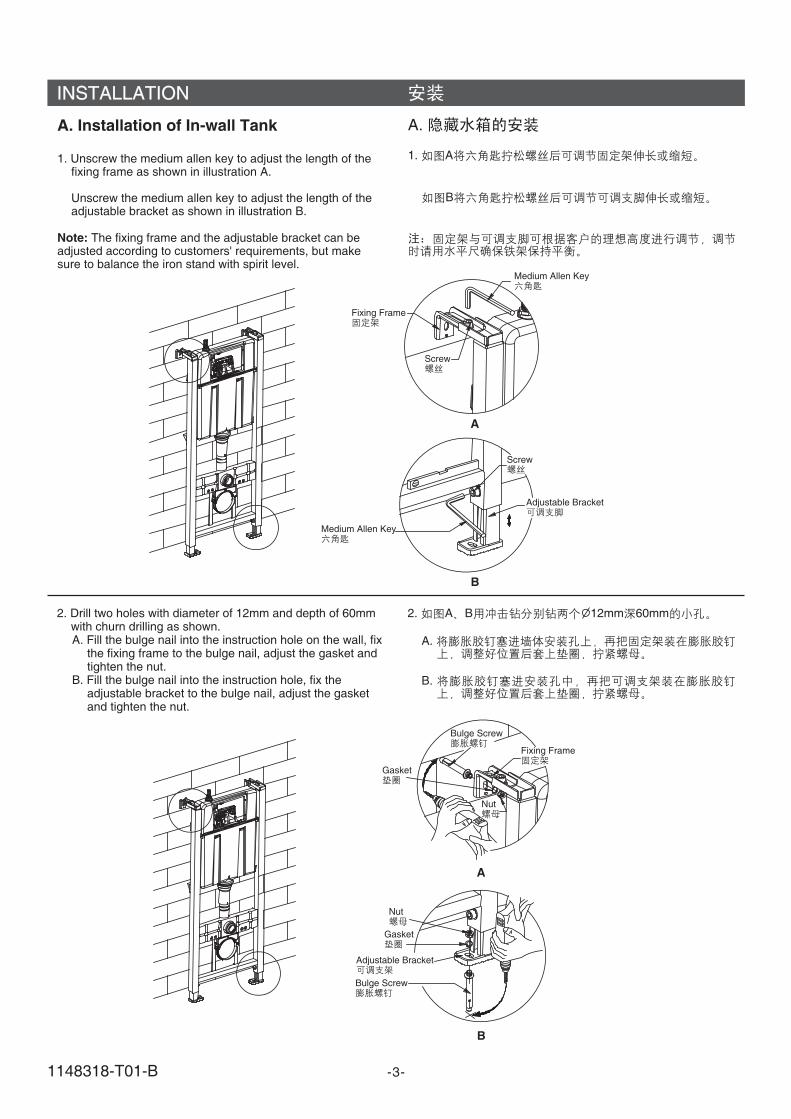
2. Drill two holes with diameter of 12mm and depth of 60mmwith churn drilling as shown.A. Fill the bulge nail into the instruction hole on the wall, fix
the fixing frame to the bulge nail, adjust the gasket andtighten the nut.
B. Fill the bulge nail into the instruction hole, fix theadjustable bracket to the bulge nail, adjust the gasketand tighten the nut.
2. A B 12mm 60mm
A.
B.
-3-
INSTALLATION
A. Installation of In-wall Tank
1. Unscrew the medium allen key to adjust the length of thefixing frame as shown in illustration A.
Unscrew the medium allen key to adjust the length of theadjustable bracket as shown in illustration B.
The fixing frame and the adjustable bracket can beadjusted according to customers' requirements, but makesure to balance the iron stand with spirit level.
Note:
A.
1. A
B
Screw
Screw
Medium Allen Key
Medium Allen Key
Adjustable Bracket
Adjustable Bracket
Fixing Frame
Fixing Frame
A
A
B
B
Bulge Screw
Bulge Screw
Gasket
Gasket
Nut
Nut
1148318-T01-B
-4-
3. Tighten the nut with the spanner as shown in illustration A.
Tighten the nut with the spanner as shown in illustration B.
3. A
B
A
B
Nut
Nut
Spanner
Spanner
B. Installation of S-trap
1. Loosen the knob open on the fixing frame, put thedrainage pipe into the fixing frame, then adjust and tightenthe knob lock . Fill the bottom of the drainage pipe in thedrainage hole .
" "
" "
B.
1. openlock
Drainage Pipe
Tank Bracket
Bottom of the Drainage Pipe
Drainage Hole
Fixing Frame
Knob
1148318-T01-B
RectangularShield
Screw
WaterTank
BlockScreen
-5-
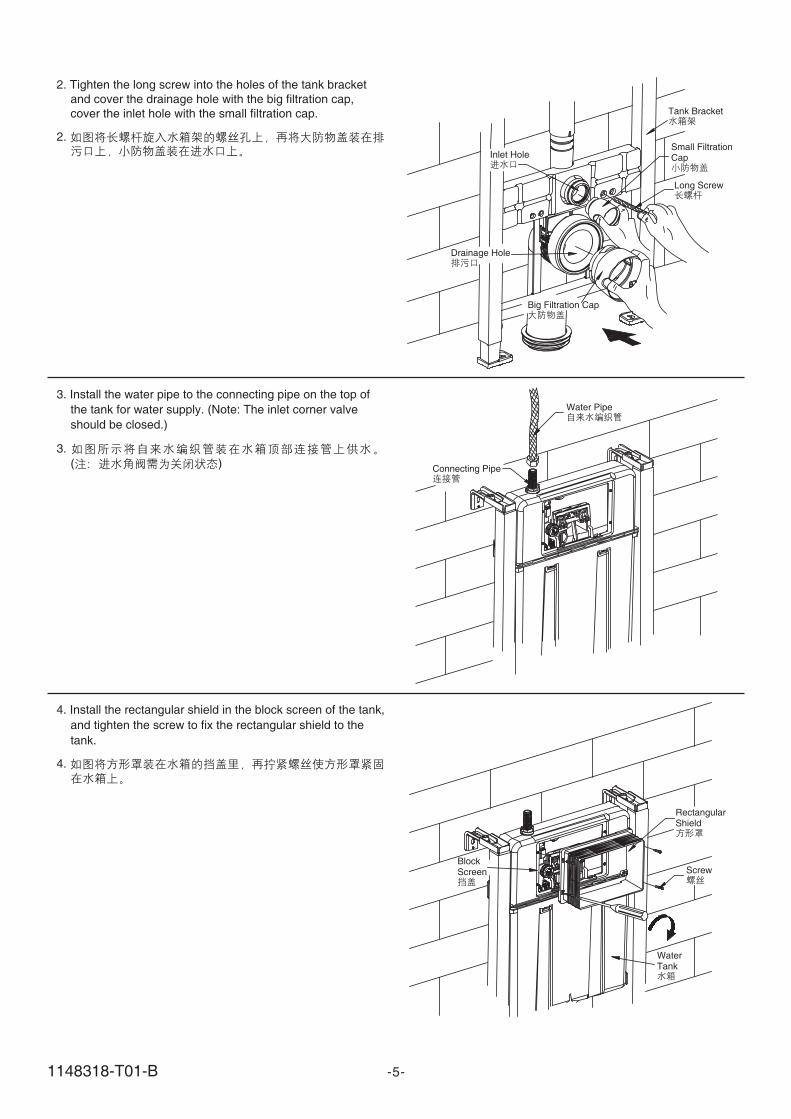
3. Install the water pipe to the connecting pipe on the top of
the tank for water supply. (Note: The inlet corner valve
should be closed.)
3.
( )
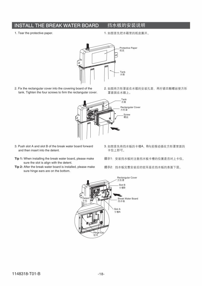
2. Tighten the long screw into the holes of the tank bracket
and cover the drainage hole with the big filtration cap,
cover the inlet hole with the small filtration cap.
2.
Inlet Hole
Drainage Hole
Big Filtration Cap
Tank Bracket
Small FiltrationCap
Long Screw
Water Pipe
Connecting Pipe
4. Install the rectangular shield in the block screen of the tank,
and tighten the screw to fix the rectangular shield to the
tank.
4.
1148318-T01-B
C. Installation of P-trap
1. Loosen the knob open on the fixing frame, put thedrainage straight pipe into the fixing frame, then adjust andtighten the knob lock . Fill the bottom of the drainagestraight pipe in the drainage hole.
" "
" "
C.
1. openlock
-6-
Fixing Frame
Fixing Frame
Knob
Water Tank Bracket
Drainage Straight Pipe
2. Tighten the long screw into the holes of the tank bracketand cover the drainage hole with the big filtration cap,cover the inlet hole with the small filtration cap.
2.
Long Screw
Inlet Hole
Drainage Cap
Big Filtration Cap
Water Tank Bracket
Small Filtration Cap
1148318-T01-B
-7-
3.
3. When finishing the brickwork of the wall, take out the bigand small filtration caps, and eliminate unwantedrectangular shield with a sharp knife.
Big Filtration Cap
Small Filtration Cap
Rectangular Shield
D. Installation of Toilet
1. Install the inlet pipe to the lavatory as shown, and mark onthe pipes at the back side of the tank with a ruler and apencil, and reserve appropriate space according to thedistance from the back of the tank to the inlet hole on thewall.
D.
1.
Inlet Pipe
Drainage Pipe
1148318-T01-B
-8-
2.
Inlet Pipe
Reserved Space
Drainage Pipe
3. Install the big and small leak-proof gaskets on inlet pipeand outlet pipe ,then install it to corresponding pipes on thetoilet tank.
3.
Small Leak-proof Gasket
Inlet Pipe
Drainage Pipe
Big Leak-proof Gasket
2. Eliminate unwanted part of the inlet pipe according to themarks of reserved space ,and rasp a smooth surface withfiles.
4. 48mm-58mm of the long screw shall be reserved outsidethe wall as shown in the illustration. if the long screwoutside the wall is not long enough or much longer thanthat needed, it should be adjusted with screwdriver or byhand. Then apply lubricant to drainage pipe and limberpipe to ensure a smooth installation.
4. 48mm-58mm
48mm-58mm
Long Screw
Lubricant
1148318-T01-B
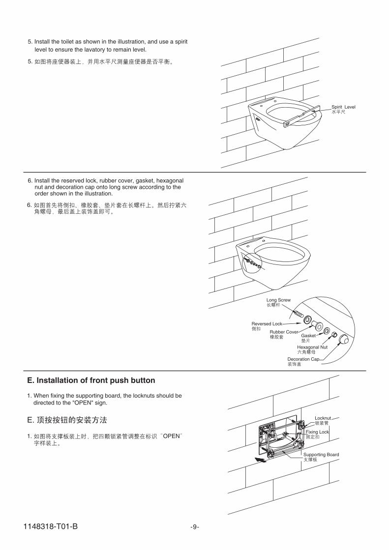
5. Install the toilet as shown in the illustration, and use a spirit
level to ensure the lavatory to remain level.
5.
Spirit Level
Gasket
Long Screw
Reversed Lock
Rubber Cover
Hexagonal Nut
Decoration Cap
6. Install the reserved lock, rubber cover, gasket, hexagonalnut and decoration cap onto long screw according to theorder shown in the illustration.
6.
-9-
E. Installation of front push button
1.
" "
When fixing the supporting board, the locknuts should be
directed to the OPEN sign.
E.
1. OPEN
Supporting Board
Locknut
Fixing Lock
1148318-T01-B
-10-
Supporting Board
Locknut
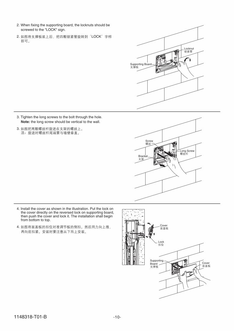
2.
" "
When fixing the supporting board, the locknuts should be
screwed to the LOCK sign.
2. LOCK
3. Tighten the long screws to the bolt through the hole.
the long screw should be vertical to the wall.Note:
3.
Bracket
Screw
Long Screw
4. Install the cover as shown in the illustration. Put the lock onthe cover directly on the reversed lock on supporting board,then push the cover and lock it. The installation shall beginfrom bottom to top.
4. Cover
CoverSupportingBoard
Lock
1148318-T01-B
1.
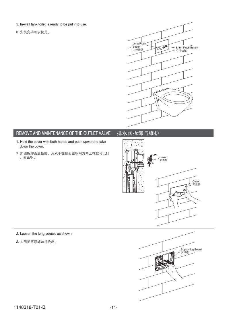
1. Hold the cover with both hands and push upward to take
down the cover.
2.
2. Loosen the long screws as shown.
5. In-wall tank toilet is ready to be put into use.
5.
Short Flush Button
Long FlushButton
-11-
REMOVE AND MAINTENANCE OF THE OUTLET VALVEREMOVE AND MAINTENANCE OF THE OUTLET VALVE
Cover
Cover
Supporting Board
1148318-T01-B
-12-
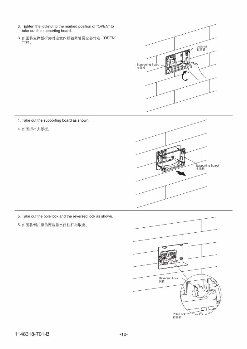
3. Tighten the locknut to the marked position of OPEN totake out the supporting board.
" "
3. OPEN
Locknut
Supporting Board
Supporting Board
4. Take out the supporting board as shown.
4.
5. Take out the pole lock and the reversed lock as shown.
5.
Reversed Lock
Pole Lock
1148318-T01-B
-13-
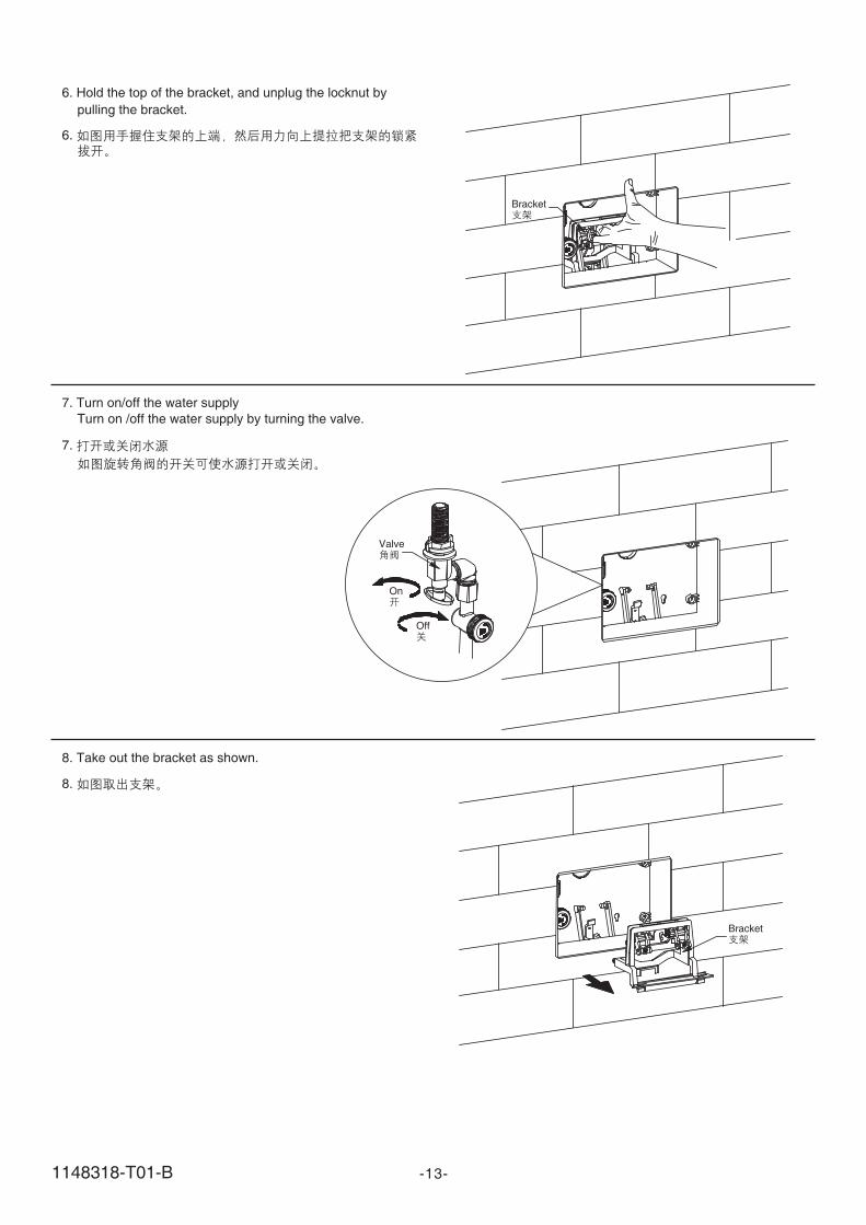
6. Hold the top of the bracket, and unplug the locknut by
pulling the bracket.
6.
8. Take out the bracket as shown.
7. Turn on/off the water supply
Turn on /off the water supply by turning the valve.
7.
8.
Bracket
Bracket
Valve
On
Off
1148318-T01-B
10. Loosen the filter nut as shown and take out the inlet valveto clean or adjust.
10.
Inlet Valve
Fixing Lock
FixingLock
11. Hold the upside of the fixing lock, and take it out as
shown.
11.
-14-
9. Loosen the filter nut as shown, and then take out the inletvalve.
9.
Nut
Filter
Loosen
Tighten
1148318-T01-B
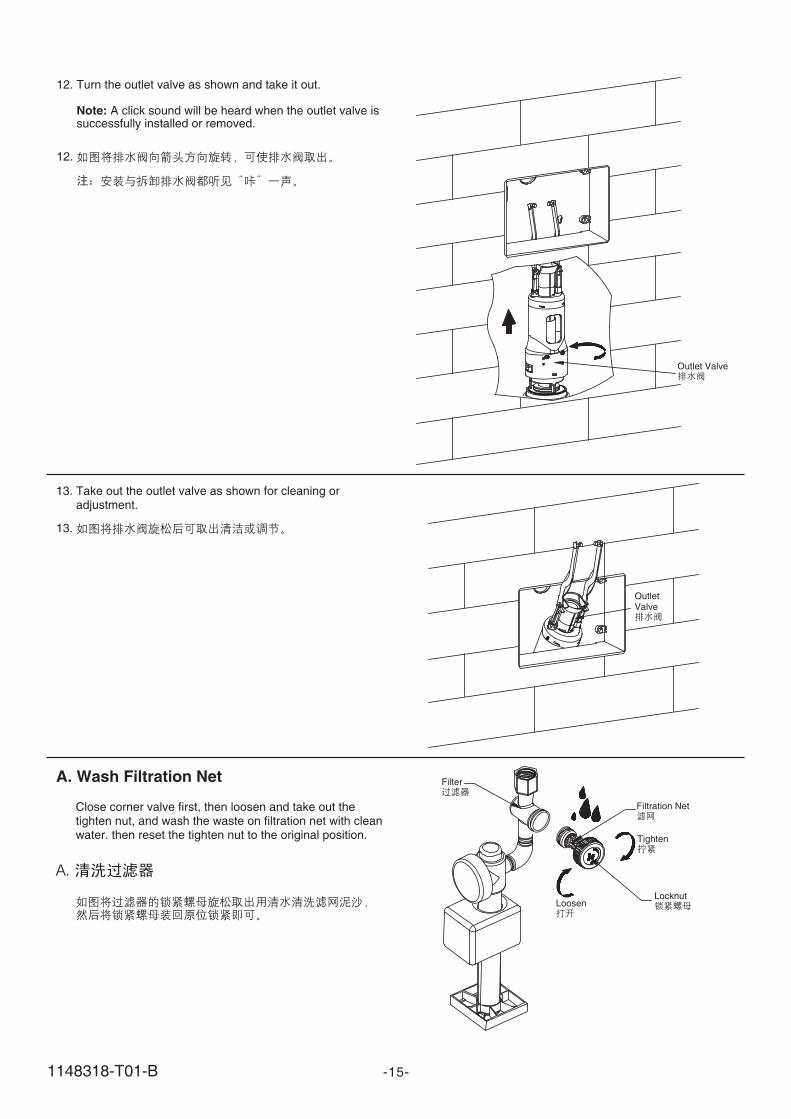
13. Take out the outlet valve as shown for cleaning oradjustment.
13.
-15-
OutletValve
12. Turn the outlet valve as shown and take it out.
A click sound will be heard when the outlet valve issuccessfully installed or removed.Note:
12.
Outlet Valve
A. Wash Filtration Net
Close corner valve first, then loosen and take out thetighten nut, and wash the waste on filtration net with cleanwater. then reset the tighten nut to the original position.
A.
Filtration Net
Filter
Loosen
Tighten
Locknut
1148318-T01-B
-16-
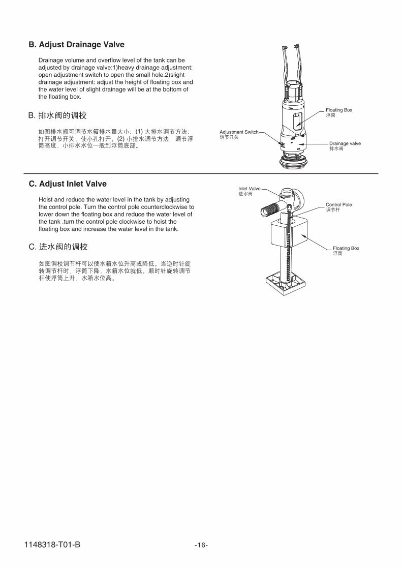
C.
Control Pole
Inlet Valve
Floating Box
C. Adjust Inlet Valve
Hoist and reduce the water level in the tank by adjusting
the control pole. Turn the control pole counterclockwise to
lower down the floating box and reduce the water level of
the tank .turn the control pole clockwise to hoist the
floating box and increase the water level in the tank.
B.
(1)(2)
Floating Box
Drainage valve
Adjustment Switch
B. Adjust Drainage Valve
Drainage volume and overflow level of the tank can beadjusted by drainage valve:1)heavy drainage adjustment:open adjustment switch to open the small hole.2)slightdrainage adjustment: adjust the height of floating box andthe water level of slight drainage will be at the bottom ofthe floating box.