3000 Watt AC Generator Model No. 580.329120 Part No. 186956 Draft 1 (07/11/2001) Generator Customer Helpline 1-800-222-3136 Sears, Roebuck and Co., Hoffman Estates, IL 60179 Owner’s Manual CAUTION: Before using this product, read this manual and follow all its Safety Rules and Operating Instructions. Visit our Craftsman website: www.sears.com/craftsman • Safety • Assembly • Operation • Maintenance • Parts • Español HOURS: Mon. - Fri. 8 a.m. to 5 p.m. (CT)
Transcript
3000 WattAC Generator
Model No.580.329120
Part No. 186956 Draft 1 (07/11/2001)
GeneratorCustomer Helpline1-800-222-3136
Sears, Roebuck and Co., Hoffman Estates, IL 60179
Owner’s Manual
CAUTION:Before using this product, read thismanual and follow all its Safety Rulesand Operating Instructions.
LIMITED WARRANTY FOR CRAFTSMAN GENERATORSSEARS warrants to the original purchaser that the alternator and engine for its portable generator will be freefrom defects in materials or workmanship for the items and period set forth below from the date of originalpurchase. This warranty is not transferable.
CONSUMER* COMMERCIAL*Alternator 1 year 90 Days
Engine 1 year 90 Days* NOTE: For the purpose of this warranty “Consumer Use” means personal residential household and emergencyuse by original purchaser, not to be used as a primary source of power. “Commercial Use” means all other uses,including rental, construction, commercial, and income producing purposes. Once a generator has experiencedcommercial use, it shall thereafter be considered a commercial use generator for the purpose of this warranty.
During said warranty period, SEARS will, at its option, repair or replace any part which, upon examination bySEARS, is found to be defective under normal use and service**. Starting batteries are not warranted by SEARS.All transportation costs under warranty, including return to the factory if necessary, are to be borne by thepurchaser and prepaid by him. This warranty does not cover normal maintenance and service and does not applyto a generator set, alternator or engine, or parts which have been subjected to improper or unauthorizedinstallation or alteration, misuse, negligence, accident, overloading, over-speeding, improper maintenance, repairor storage so as, in SEARS’s judgment, to adversely affect its performance and reliability.
** NORMAL WEAR: As with all mechanical devices, engines need periodic parts service and replacement toperform well. This warranty will not cover repair when normal use has exhausted the life of a part or engine.
THERE IS NO OTHER EXPRESS WARRANTY. SEARS HEREBY DISCLAIMS ANY AND ALL IMPLIEDWARRANTIES, INCLUDING BUT NOT LIMITED TO THOSE OF MERCHANTABILITY AND FITNESSFOR A PARTICULAR PURPOSE TO THE EXTENT PERMITTED BY LAW. THE DURATION OF ANYIMPLIED WARRANTIES WHICH CANNOT BE DISCLAIMED IS LIMITED TO THE TIME PERIOD ASSPECIFIED IN THE EXPRESS WARRANTY. LIABILITY FOR CONSEQUENTIAL, INCIDENTAL, ORSPECIAL DAMAGES UNDER ANY AND ALL WARRANTIES IS EXCLUDED.
Some provinces do not allow limitations on how long an implied warranty lasts, or the exclusion or limitation ofincidental or consequential damages, so the above limitations or exclusions may not apply to you. This warrantygives you specific legal rights and you may also have other rights, which vary from state to state.
For service, see your nearest SEARS authorized warranty service facility. Warranty service can be performedonly by a SEARS authorized service facility. This warranty will not apply to service at any other facility. At the timeof requesting warranty service, evidence of original purchase date must be presented.
SEARS, ROEBUCK and CO., D/817WA, Hoffman Estates, IL 60179 U.S.A.
WARRANTY
3
SAFETY RULES
CAUTION! Before using this product, read thismanual and follow all Safety Rules andOperating Instructions.
WARNING! You must isolate the generatorfrom the electric utility by opening the electricalsystem’s main circuit breaker or main switch ifthis unit is used for backup power. Failure toisolate the generator from the power utilitymay result in injury or death to electric utilityworkers and damage to the generator due toa backfeed of electrical energy. When used asbackup power, the local power utility must benotified.
DANGER! Generator exhaust gases containDEADLY carbon monoxide gas. Carbonmonoxide, if breathed in sufficientconcentrations, will cause unconsciousnessor death. Operate this equipment outdoorswhere adequate ventilation is available.
CAUTION! To prevent accidental starting whensetting up, transporting, adjusting or makingrepairs to your generator, always disconnectspark plug wire and place the wire where itcannot contact the spark plug.
• The unit requires an adequate flow of cooling airfor its continued proper operation. Never operatethe unit inside any room or enclosure where thefree flow of cooling air into and out of the unit mightbe obstructed. Allow at least 3 feet of clearance onall sides of generator or you could damage the unit.
• The generator produces dangerously high voltagethat can cause extremely hazardous electricalshock. Avoid contact with bare wires, terminals,etc. Never permit any untrained person to operateor service the generator.
• Do Not overfill the fuel tank. Always allow room forfuel expansion. If tank is overfilled, fuel canoverflow onto a hot engine and cause FIRE or anEXPLOSION.
• Never operate the generator:in rain; in any enclosed compartment; whenconnected electrical devices overheat; if electricaloutput is lost; if engine or generator sparks; if flameor smoke is observed while unit is running; if unitvibrates excessively.
• Never handle any kind of electrical cord or devicewhile standing in water, while barefoot or whilehands or feet are wet. Dangerous electrical shockwill result.
• Use a ground fault circuit interrupter in any dampor highly conductive area (such as metal decking orsteel work).
• Do Not use worn, bare, frayed or otherwisedamaged electrical cord sets with the generator.Using any defective cord set may result in electricalshock or damage to property.
• Operate generator only on level surfaces andwhere it will not be exposed to excessive moisture,dirt, dust or corrosive vapors.
• Gasoline is highly FLAMMABLE and its vapors areEXPLOSIVE. Do Not permit smoking, open flames,sparks or heat in the vicinity while handlinggasoline. Avoid spilling gasoline on a hot engine.Comply with all laws regulating storage andhandling of gasoline.
• Never store generator with fuel in tank wheregasoline vapors might reach an open flame orspark or pilot light (as on a furnace, water heater orclothes dryer). FIRE or EXPLOSION may result.
• Never add fuel while unit is running.• Never start or stop the unit with electrical loads
connected to receptacles AND with connecteddevices turned ON. Start the engine and let itstabilize before connecting electrical loads.Disconnect all electrical loads before shutting downthe generator.
• Do Not insert any object through cooling slots ofthe engine-generator.
NOTE: Your generator is equipped with a sparkarrester muffler. The spark arrester must bemaintained in effective working order by the owner/operator. In the State of California, a spark arrester isrequired by law (Section 4442 of the California PublicResources Code). Other states may have similar laws.Federal laws apply on federal lands.
The engine exhaust from this productcontains chemicals known to the State of
California to cause cancer, birth defects, orother reproductive harm.
WARNING:
THIS IS THE SAFETY ALERT SYMBOL. IT IS USED TO ALERT YOU TO POTENTIALPERSONAL INJURY HAZARDS. OBEY ALL SAFETY MESSAGES THAT FOLLOW THISSYMBOL TO AVOID POSSIBLE INJURY OR DEATH.
4
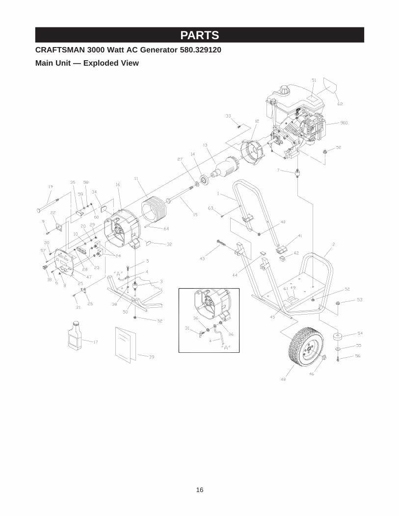
KNOW YOUR GENERATORRead the owner’s manual and safety rules before operating your generator.Compare the illustrations with your generator to familiarize yourself with the locations of various controls andadjustments. Save this manual for future reference.
12 Volt DC, 10 Amp Receptacle — Charges a12 Volt automotive type battery.
120 Volt AC, 20 Amp Receptacle — May be used tosupply electrical power for the operation of 120 VoltAC, 20 Amp, single phase, 60 Hz electrical lighting,appliance, tool and motor loads.
Air Cleaner — Filters intake air as it is drawn into theengine.
Circuit Breakers — Each receptacle socket isprotected against electrical overload with “push toreset” circuit breakers.
Fuel Tank — Tank holds 1 U.S. gallon of unleadedgasoline.
Grounding Wing Nut — Ground the generator to anapproved earth ground here.
Oil Fill Cap/Dipstick — Check and fill engine with oilhere. See page 6 for oil recommendations and fillinginstructions.
Primer Button — Used when starting a cold engine.See page 7 for starting instructions.
Recoil Starter — Used for starting the engine.
Run/Stop Switch — Set switch to “Run” prior to usingrecoil starter. Set switch to “Stop” to switch off engine.
Spark Arrester Muffler — Exhaust muffler lowersengine noise and is equipped with a spark arresterscreen.
Fuel Tank
Air Cleaner
Run/StopSwitch
120 Volt AC, 20 AmpReceptacles
Circuit Breakers
12 Volt DC,10 AmpReceptacle
Spark ArresterMuffler
Primer Button
RecoilStarter
Grounding Wing Nut
Oil Fill Cap/Dipstick
5
ASSEMBLY
OPERATION
TO REMOVE GENERATOR FROMCARTON• Slice two corners at end of carton from top to
bottom so the panel can be folded down flat, thenremove all packing material.
• Remove the generator and contents from theshipping carton.
CARTON CONTENTSCheck all contents against those listed below:
• Main unit• Engine oil• Owner’s manual• Battery charge cablesIf any parts are missing or damaged, call thegenerator helpline at 1-800-222-3136.
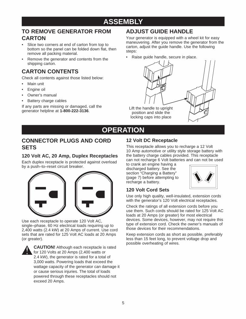
ADJUST GUIDE HANDLEYour generator is equipped with a wheel kit for easymaneuvering. After you remove the generator from thecarton, adjust the guide handle. Use the followingsteps:
• Raise guide handle, secure in place.
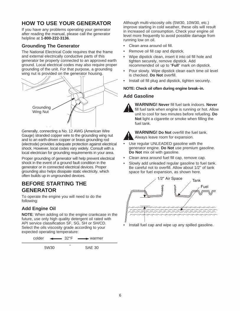
CONNECTOR PLUGS AND CORDSETS120 Volt AC, 20 Amp, Duplex ReceptaclesEach duplex receptacle is protected against overloadby a push–to–reset circuit breaker.
Use each receptacle to operate 120 Volt AC,single–phase, 60 Hz electrical loads requiring up to2,400 watts (2.4 kW) at 20 Amps of current. Use cordsets that are rated for 125 Volt AC loads at 20 Amps(or greater).
CAUTION! Although each receptacle is ratedfor 120 Volts at 20 Amps (2,400 watts or2.4 kW), the generator is rated for a total of3,000 watts. Powering loads that exceed thewattage capacity of the generator can damage itor cause serious injuries. The total of loadspowered through these receptacles should notexceed 20 Amps.
12 Volt DC ReceptacleThis receptacle allows you to recharge a 12 Volt10 Amp automotive or utility style storage battery withthe battery charge cables provided. This receptaclecan not recharge 6 Volt batteries and can not be usedto crank an engine having adischarged battery. See thesection “Charging a Battery”(page 7) before attempting torecharge a battery.
120 Volt Cord SetsUse only high quality, well-insulated, extension cordswith the generator’s 120 Volt electrical receptacles.
Check the ratings of all extension cords before youuse them. Such cords should be rated for 125 Volt ACloads at 20 Amps (or greater) for most electricaldevices. Some devices, however, may not require thistype of extension cord. Check the owner’s manuals ofthose devices for their recommendations.
Keep extension cords as short as possible, preferablyless than 15 feet long, to prevent voltage drop andpossible overheating of wires.
Lift the handle to uprightposition and slide the
locking caps into place
6
HOW TO USE YOUR GENERATORIf you have any problems operating your generatorafter reading the manual, please call the generatorhelpline at 1-800-222-3136.
Grounding The GeneratorThe National Electrical Code requires that the frameand external electrically conductive parts of thisgenerator be properly connected to an approved earthground. Local electrical codes may also require propergrounding of the unit. For that purpose, a groundingwing nut is provided on the generator housing.
Generally, connecting a No. 12 AWG (American WireGauge) stranded copper wire to the grounding wing nutand to an earth-driven copper or brass grounding rod(electrode) provides adequate protection against electricalshock. However, local codes vary widely. Consult with alocal electrician for grounding requirements in your area.
Proper grounding of generator will help prevent electricalshock in the event of a ground fault condition in thegenerator or in connected electrical devices. Propergrounding also helps dissipate static electricity, whichoften builds up in ungrounded devices.
BEFORE STARTING THEGENERATORTo operate the engine you will need to do thefollowing:
Add Engine OilNOTE: When adding oil to the engine crankcase in thefuture, use only high quality detergent oil rated withAPI service classification SF, SG, SH or SH/CD.Select the oils viscosity grade according to yourexpected operating temperature:
Although multi-viscosity oils (5W30, 10W30, etc.)improve starting in cold weather, these oils will resultin increased oil consumption. Check your engine oillevel more frequently to avoid possible damage fromrunning low on oil.
• Clean area around oil fill.• Remove oil fill cap and dipstick.• Wipe dipstick clean, insert it into oil fill hole and
tighten securely, remove dipstick. Addrecommended oil up to “Full” mark on dipstick.
• Pour slowly. Wipe dipstick clean each time oil levelis checked. Do Not overfill.
• Install oil fill plug and dipstick, tighten securely.
NOTE: Check oil often during engine break–in.
Add Gasoline
WARNING! Never fill fuel tank indoors. Neverfill fuel tank when engine is running or hot. Allowunit to cool for two minutes before refueling. DoNot light a cigarette or smoke when filling thefuel tank.
WARNING! Do Not overfill the fuel tank.Always leave room for expansion.
• Use regular UNLEADED gasoline with thegenerator engine. Do Not use premium gasoline.Do Not mix oil with gasoline.
• Clean area around fuel fill cap, remove cap.• Slowly add unleaded regular gasoline to fuel tank.
Be careful not to overfill. Allow about 1/2" of tankspace for fuel expansion, as shown here.
• Install fuel cap and wipe up any spilled gasoline.
colder 32°F warmer
5W30 SAE 30
GroundingWing Nut
7
To Start The Engine• Unplug all electrical loads from the generator
receptacles before starting the engine. Never startor stop the engine with electrical devicesconnected to the receptacles AND turned on.
• Be sure the spark plug wire is attached to the sparkplug.
• Place the Run/Stop switch in the “RUN” position.• Push the primer button 2 or 3 times. Wait about
2 seconds between each push. In cold weather(50°F/10°C or below) push 5 times.
NOTE: Primer may be needed to restart a warmengine after a short shutdown.
• Grasp starter grip and slowly pull the rope until youfeel some resistance, then pull the cord out with arapid full arm stroke. Let rope return slowly. Do Notlet rope “snap back” against engine.
NOTE: If the engine fails to start after 3 pulls, push theprimer button 2 times and pull the starter rope again.
WARNING! Never run engine in enclosedpoorly ventilated areas. Engine exhaustcontains carbon monoxide, an odorless anddeadly gas.
CAUTION! Temperature of muffler and nearbyareas may exceed 150°F (65°C). Avoid theseareas.
Connecting Electrical Loads• Let the engine stabilize and warm up for a few
minutes after starting.• Do Not connect 240 Volt loads to 120 Volt
receptacles.• Do Not connect 3–phase loads to the generator.• Do Not connect 50 Hz loads to the generator.• Plug in and turn on the desired 120 Volt AC, single
phase, 60 Hertz electrical loads.• DO NOT OVERLOAD THE GENERATOR. Add up
the rated watts (or amps) of all loads to beconnected at one time. This total should not begreater than the rated wattage/amperage capacityof the generator. See “Don’t Overload theGenerator” on page 9.
Stopping the Engine• Unplug all electrical loads from the unit. Never start
or stop the engine with electrical devices pluggedin and turned on.
• Let the engine run at no-load for two minutes tostabilize the units internal temperatures.
• Move the Run/Stop switch to “STOP” position.
Cold Weather OperationYour unit is equipped with an anti-icing air cleanerfeature to enable the unit to run at temperatures below32°F, without ice forming in the carburetor. The aircleaner base will have an opening which draws warmair from the muffler into the air cleaner housing. Towork effectively, it is necessary to block cold air fromentering the air cleaner.
In temperatures 32°F and below:• Remove wing nut from air cleaner cover.• Remove air cleaner cover from base.• Remove red baffle from inside of air cleaner cover.• Insert red baffle in “winter” position as shown.
• Reinstall air cleaner cover onto base.• Reinstall wing nut and tighten securely.In temperatures above 32°F:• Follow above directions, removing baffle from
“winter” position and reinstalling in “summer”position.
PrimerButton
Baffle shown in“Winter” Position
Baffle in “Summer”Position
Base Paper Element
Wing Nut
Air Cleaner Cover
8
Charging a Battery
WARNING! Storage batteries emit explosivegas while charging that remains around abattery for a long time after it has been charged.The slightest spark can ignite the gas, causingan explosion that can shatter the battery andcause blindness or other injury.
WARNING! Do Not permit smoking, openflame, sparks or any other source of heataround a battery. Do Not use a lighter or otherflame for checking battery fluid levels. Wearprotective goggles, rubber apron and rubbergloves when working around a battery. Batteryelectrolyte fluid is an extremely caustic sulfuricacid solution that can cause severe burns. DoNot permit fluid contact with eyes, skin, clothing,etc. If spill occurs, flush area with clear waterimmediately.
Your generator has the capability of recharging adischarged 12 Volt automotive or utility style storagebattery. Do Not use the unit to charge any 6 Voltbatteries. Do Not use the unit to crank an enginehaving a discharged battery.
To recharge 12 Volt batteries, proceed as follows:• If necessary, clean battery posts or terminals.• Check fluid level in all battery cells. If necessary,
add ONLY distilled water to cover separators inbattery cells. Do Not use tap water.
• If the battery is equipped with vent caps, makesure they are installed and are tight.
• Connect battery charge cable connector plug topanel receptacle identified by the words“12 VOLT D.C.”
• Connect battery charge cable clamp with redhandle to battery post or terminal indicated byPOSITIVE, POS or (+).
• Connect battery charge cable clamp with blackhandle to battery post or terminal indicated byNEGATIVE, NEG, or (–).
• Start engine. Let the engine run while batteryrecharges.
• When battery has charged, shut down engine (see“Stopping the Engine”).
NOTE: Use an automotive hydrometer to test batterystate of charge and condition. Follow the hydrometermanufacturer’s instructions carefully. Generally, abattery is considered to be at 100% state of chargewhen specific gravity of its fluid (as measured byhydrometer) is 1.260 or higher.
9
DON’T OVERLOAD THEGENERATOROverloading a generator in excess of its rated wattagecapacity can result in damage to the generator and toconnected electrical devices. Observe the following, toprevent overloading the unit:
• Add up the total wattage of all electrical devices tobe connected at one time. This total should NOTbe greater than the generator’s wattage capacity.
• The rated wattage of lights can be taken from lightbulbs. The rated wattage of tools, appliances andmotors can usually be found on a data plate ordecal affixed to the device.
• If the appliance, tool or motor does not givewattage, multiply volts times ampere rating todetermine watts (volts x amps = watts).
• Some electric motors, such as induction types,require about three times more watts of power forstarting than for running. This surge of power lastsonly a few seconds when starting such motors.Make sure you allow for this high starting wattagewhen selecting electrical devices to connect to yourgenerator. First, figure the watts needed to start thelargest motor. Add to that figure the running wattsof all other connected loads.
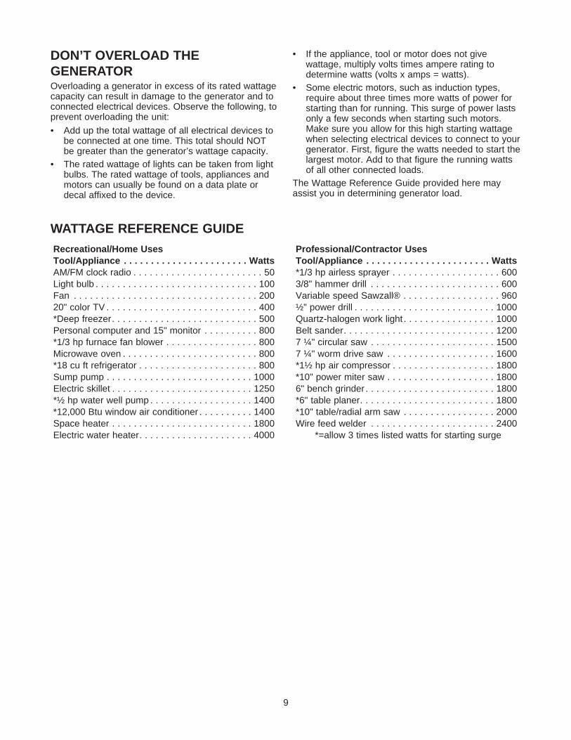
The Wattage Reference Guide provided here mayassist you in determining generator load.
GENERAL RECOMMENDATIONSThe generator warranty does not cover items thathave been subjected to operator abuse or negligence.To receive full value from the warranty, operator mustmaintain generator as instructed in this manual.
Some adjustments will need to be made periodically toproperly maintain your generator.
NOTE: The proper tire inflation operating range shouldbe 15-40 PSI.
All adjustments in this section should be made at leastonce each season. Follow the requirements in the“Maintenance Schedule” chart shown above.
NOTE: Once a year you should clean or replace thespark plug and replace the air filter. A new spark plugand clean air filter assure proper fuel-air mixture andhelp your engine run better and last longer.
GENERATOR MAINTENANCEGenerator maintenance consists of keeping the unitclean and dry. Operate and store the unit in a cleandry environment where it will not be exposed toexcessive dust, dirt, moisture or any corrosive vapors.Cooling air slots in the generator must not becomeclogged with snow, leaves,or any other foreignmaterial.
Check the cleanliness of the generator frequently andclean when dust, dirt, oil, moisture or other foreignsubstances are visible on its exterior surface.
NOTE: Do Not use a garden hose to clean generator.Water can enter the engine fuel system and causeproblems. In addition, if water enters the generatorthrough cooling air slots, some of the water will beretained in voids and cracks of the rotor and statorwinding insulation. Water and dirt buildup on thegenerator internal windings will eventually decreasethe insulation resistance of these windings.
MAINTENANCE SCHEDULEFollow the hourly or calendar intervals, whichever occurs first.
More frequent service is required when operating in adverse conditions noted below.
‡ Change oil after first 2 hours of operation then after every 50 hours or every season.
* Change oil every 25 hours when operating under heavy load or in high temperatures.
** Clean more often under dirty or dusty conditions. Replace cleaner parts if very dirty.
MAINTENANCE
Maintenance Operation Every 5 Hours 20 Hours orEvery Season
50 Hours orEvery Season
100 Hours orEvery Season
Check oil level XClean spark arrester screen X*Change oil ‡ XService air cleaner cartridge X**Replace spark plugs X
11
To Clean the Generator:• Use a damp cloth to wipe exterior surfaces clean.• A soft bristle brush may be used to loosen caked
on dirt, oil, etc.
CAUTION! Never insert any object or toolthrough the air cooling slots, even if the engineis not running.
• A vacuum cleaner may be used to pick up loosedirt and debris.
• Low pressure air (not to exceed 25 psi) may beused to blow away dirt. Inspect cooling air slotsand openings on the generator. These openingsmust be kept clean and unobstructed.
CAUTION! When working on the generatoralways disconnect spark plug wire from sparkplug and keep it away from spark plug.
ENGINE MAINTENANCEChecking Oil LevelOil level should be checked prior to each use or atleast every 5 hours of operation. Keep oil levelmaintained.
Changing Engine OilChange the oil after the first 2 hours of operation.Change oil every 50 hours thereafter. If you are usingyour generator under extremely dirty or dustyconditions, or in extremely hot weather, change the oilmore often.
Change the oil while the engine is still warm fromrunning, as follows:
• Clean area around oil drain plug. The oil drain plugis located at the base of the engine, opposite thecarburetor.
• Install oil drain plug and tighten securely.• Fill oil sump with recommended oil. See page 6 for
oil recommendations.• Install the oil cap/dipstick. Check oil level. Tighten
cap securely.• Wipe up any spilled oil.
Clean/Replace Spark PlugChange the spark plug every 100 hours of operationor once each year, whichever comes first. This willhelp your engine to start easier and run better.
• Clean the area around the spark plug.• Remove and inspect the spark plug.• Replace the spark plug if electrodes are pitted or
burned or the porcelain is cracked. Forreplacement use Champion RN4C or equivalent.
• Check electrode gap with wire feeler gauge and setspark plug gap to 0.030 inch (0.76mm) ifnecessary.
Service Air CleanerYour engine will not run properly and may bedamaged if you run it using a dirty air filter element.
Clean or replace the paper air filter element onceevery 100 hours of operation or once each season,whichever comes first. Clean or replace more often ifoperating under dusty or dirty conditions.
To clean or replace paper air filter:• Remove the wing nut and air cleaner cover and
remove the paper filter.
• Clean the inside of the base and cover thoroughly.• Clean the paper filter by tapping it gently on a solid
surface. If the filter is too dirty, replace it with a newone. Dispose of the old filter properly.
NOTE: If you need to order a new air filter element,please call 1-800-366-PART.
Clean Spark Arrester ScreenThe engine exhaust muffler has a spark arresterscreen. Inspect and clean the screen every 20 hoursof operation or once each year, whichever comes first.
NOTE: If you use your generator on any forest-covered, brush-covered or grass-covered unimprovedland, it must have a spark arrester installed. The sparkarrester must be maintained in good condition by theowner/operator.
Base
Paper Filter
Cover
Wing Nut
12
GENERALThe generator should be started at least once everyseven days and allowed to run at least 30 minutes. Ifthis cannot be done and you must store the unit formore than 30 days, use the following information as aguide to prepare it for storage.
Long Term Storage Instructions
WARNING! Never store engine with fuel intank indoors or in enclosed, poorly ventilatedareas where fumes may reach an open flame,spark or pilot light as on a furnace, water heater,clothes dryer or other gas appliance.
It is important to prevent gum deposits from forming inessential fuel system parts such as the carburetor, fuelfilter, fuel hose or tank during storage. Also,experience indicates that alcohol-blended fuels (calledgasohol, ethanol or methanol) can attract moisture,which leads to separation and formation of acidsduring storage. Acidic gas can damage the fuelsystem of an engine while in storage.
To avoid engine problems, the fuel system should beemptied before storage of 30 days or longer. Followthese instructions:
Protect Fuel System
WARNING! Drain fuel into approved containeroutdoors, away from open flame. Be sureengine is cool. Do Not smoke.
• Remove all gasoline from the fuel tank to preventgum deposits from forming on these parts andcausing possible engine malfunction.
• Run engine until engine stops from lack of fuel.
Change OilWhile engine is still warm, drain oil from crankcase.Refill with recommended grade.
Oil Cylinder Bore• Remove spark plug and pour about 1 ounce (30ml)
of clean engine oil into the cylinder.
CAUTION! Avoid spray from spark plug holewhen cranking engine slowly.
• Install spark plug. Do Not connect spark plug wire.
Generator• Clean the generator as outlined on page 11 (“To
Clean the Generator”).• Check that cooling air slots and openings on
generator are open and unobstructed.
Other Storage Tips• Do Not store gasoline from one season to another.• Replace your gasoline can if the can starts to rust.
Rust and/or dirt in your gasoline will causeproblems.
• If possible, store your unit indoors and cover it togive protection from dust and dirt. BE SURE TOEMPTY THE FUEL TANK.
• Cover your unit with a suitable protective cover thatdoes not retain moisture.
• Store generator in clean, dry area.IMPORTANT: Never cover your generator whileengine and exhaust area are warm.
STORAGE
Clean and inspect the spark arrester as follows:
• Remove the screw that attaches the spark arresterscreen.
• Inspect the screen and replace if torn, perforatedor otherwise damaged. Do Not use a defectivescreen. If screen is not damaged, clean it withcommercial solvent.
• Reattach the screen.
SparkArresterMuffler
Problem Cause Correction
Engine is running, butno AC output isavailable.
1. One of the circuit breakers is open.2. Fault in generator.3. Poor connection or defective cord set.4. Connected device is bad.
1. Reset circuit breaker.2. Contact Sears service facility.3. Check and repair.4. Connect another device that is in
good condition.
Engine runs good atno-load but “bogsdown" when loadsare connected.
1. Short circuit in a connected load.2. Engine speed is too slow.3. Generator is overloaded.
4. Shorted generator circuit.
1. Disconnect shorted electrical load.2. Contact Sears service facility.3. See “Don't Overload the
Generator” on page 9.4. Contact Sears service facility.
Engine will not start;or starts and runsrough.
1. Run/Stop Switch set to “STOP”.2. Dirty air cleaner.3. Out of gasoline.4. Stale gasoline.
5. Spark plug wire not connected tospark plug.
6. Bad spark plug.7. Water in gasoline.
8. Overprimed or flooded.
9. Excessively rich fuel mixture.10. Intake valve stuck open or closed.11. Engine has lost compression.
1. Set switch to “RUN”.2. Clean or replace air cleaner.3. Fill fuel tank.4. Drain gas tank and carburetor; fill
with fresh fuel.5. Connect wire to spark plug.
6. Replace spark plug.7. Drain gas tank and carburetor; fill
with fresh fuel.8. Wait 5 minutes and re-crank
engine.9. Contact Sears service facility.10. Contact Sears service facility.11. Contact Sears service facility.
Engine shuts downwhen running.
1. Out of gasoline. 1. Fill fuel tank.
Engine lacks power.1. Load is too high.
2. Dirty air filter.
1. See “Don't Overload the Generator”on page 9.
2. Replace air filter.
Engine “hunts” orfalters.
Carburetor is running too rich or too lean. Contact Sears service facility.
EMISSION CONTROL SYSTEM WARRANTYCALIFORNIA & US EPA EMISSIONCONTROL WARRANTY STATEMENTThe U.S. Environmental Protection Agency (“EPA”), theCalifornia Air Resources Board (“CARB”) and TecumsehProducts Co. are pleased to explain the Federal andCalifornia Emission Control Systems Warranty on your newsmall off-road engine. In California, new model year 2000and later small off-road engines must be designed, built andequipped to meet the State’s stringent anti-smog standards.In other states, new model year 1997 and later small off-road engines must be designed, built and equipped, at thetime of sale, to meet U.S. EPA regulations. TecumsehProducts Co. will warrant the emission control system onyour small off-road engine for the time periods listed below,provided there has been no abuse, neglect, unapprovedmodification, or improper maintenance of your small off-roadengine.
Your emission control system may include parts such as thecarburetor, ignition system and exhaust system. Alsoincluded may be the compression release system and otheremission-related assemblies.
Where a warrantable condition exists, Tecumseh ProductsCo. will repair your small off-road engine at no cost to youfor diagnosis, parts and labor.
Manufacturer’s Emission Control SystemWarranty CoverageEmission control systems on model year 2000 and laterCalifornia small off-road engines are warranted for twoyears as hereinafter noted. In other states, model year 1997and later small off-road engines are also warranted for twoyears. If during such warranty period, any emission-relatedpart on your engine is defective in materials orworkmanship, the part will be repaired or replaced byTecumseh Products Co.
Owner’s Warranty ResponsibilitiesAs the small off-road engine owner, you are responsible forthe performance of the required maintenance listed in yourOperating/Maintenance Instructions, but TecumsehProducts Co. will not deny warranty solely due to the lack ofreceipts or for your failure to provided written evidence ofthe performance of all scheduled maintenance.
As the small off-road engine owner, you should, however,be aware that Tecumseh Products Co. may deny youwarranty coverage if your small off-road engine or a partthereof has failed due to abuse, neglect, impropermaintenance or unapproved modifications.
You are responsible for presenting your small off-roadengine to a Tecumseh Authorized Service Outlet (anyTecumseh Registered Service Dealer, TecumsehAuthorized Service Distributor or Tecumseh CentralWarehouse Distributor) as soon as a problem exists. Thewarranty repairs should be completed in a reasonableamount of time, not to exceed 30 days.
Warranty Service can be arranged by contacting either aTecumseh Authorized Service Outlet or by contactingTecumseh Products Co., c/o Service Manager, Engine andTransmission Group Service Division, 900 North Street,Grafton, WI 53024-1499. Telephone 1-262-377-2700, or seeyour local telephone yellow pages under “Engines,Gasoline” for the name, address and telephone number of aTecumseh Authorized Service Outlet near you.
Important NoteThis warranty statement explains your rights and obligationsunder the Emission Control Warranty (“ECS Warranty”)which is provided to you by Tecumseh Products Co.pursuant to California law. Tecumseh Products Co. alsoprovides to the original purchasers of new TecumsehProducts Co. engines the Tecumseh Products Co. LimitedWarranties for New Tecumseh Engine and ElectronicIgnition Modules (“Tecumseh Products Co. Warranty”) whichis enclosed with all new Tecumseh Products Co. engines ona separate sheet. The ECS warranty applies only to theemission control system of your new engine. To the extentthat there is any conflict in terms between the ECSWarranty and the Tecumseh Products Co. Warranty, theECS Warranty shall apply except in any circumstances inwhich the Tecumseh Products Co. Warranty may provide alonger warranty period. Both the ECS Warranty and theTecumseh Products Co. Warranty describe important rightsand obligations with respect to your engine.
Warranty service can only be performed by a TecumsehProducts Co. Authorized Service Outlet, or by TecumsehProducts Co. at its factory in Grafton, WI. At the time ofrequesting warranty service, evidence must be presented ofthe date of sale to the original purchaser. The purchasershall pay any charges for making service calls and/or fortransporting the products to and from the place where theinspection and/or warranty work is performed. Thepurchaser shall be responsible for any damage or lossincurred in connection with the transportation of any engineor any part(s) there of submitted for inspection and/orwarranty work.
If you have any questions regarding your warranty rightsand responsibilities, you should contact Tecumseh ProductsCo. at 1-262-377-2700.
EMISSION CONTROL SYSTEMWARRANTYEmission Control System Warranty (“ECS Warranty”) formodel year 2000 and later California small off-road engines(for other states, model year 1997 and later small off-roadengines):
A. Applicability: This warranty shall apply to model year2000 and later California small off-road engines (for otherstates, model year 1997 and later small off-road engines.)The ECS Warranty Period shall begin on the date the newengine or equipment is delivered to its original, end-usepurchaser, and shall continue for 24 consecutive monthsthereafter.
25
B. General Emissions Warranty Coverage: TecumsehProducts Co. warrants to the original, end-use purchaser ofthe new engine or equipment and to each subsequentpurchaser that each of its small off-road engines is:
1. Designed, built and equipped so as to conform with allapplicable regulations by the Air Resources Boardpursuant to its authority in Chapters 1 and 2, Part 5,Division 26 of the Health and Safety Code, and
2. Free from defects in materials and workmanshipwhich, at any time during the ECS Warranty period,will cause a warranted emissions-related part to fail tobe identical in all materials respects to the part asdescribed in the engine manufacturer’s application forcertification.
C. The ECS Warranty only pertains to emissions-relatedparts on your engine, as follows:
1. Any warranted, emissions-related parts which are notscheduled for replacement as required maintenance inthe Operation/Maintenance Instructions shall bewarranted for the ECS Warranty Period. If any suchpart fails during the ECS Warranty Period, it shall berepaired or replaced by Tecumseh Products Co.according to Subsection 4 below. Any such partrepaired or replaced under the ECS Warranty shall bewarranted for any remainder of the ECS WarrantyPeriod.
2. Any warranted, emissions-related part which isscheduled only for regular inspection as specified inthe Operation/Maintenance Instructions shall bewarranted for the ECS Warranty Period. A statementin such written instructions to the effect of “repair orreplace as necessary,” shall not reduce the ECSWarranty Period. Any such part repaired or replacedunder the ECS Warranty shall be warranted for theremainder of the ECS Warranty Period.
3. Any warranted, emissions-related part which isscheduled for replacement as required maintenance inthe Operation/Maintenance Instructions, shall bewarranted for the period of time prior to the firstscheduled replacement point for that part. If the partfails prior to the first scheduled replacement, the partshall be repaired or replaced by Tecumseh ProductsCo. according to Subsection 4 below. Any suchemissions-related part repaired or replaced under theECS Warranty, shall be warranted for the remainder ofthe ECS Warranty period prior to the first scheduledreplacement point for such emissions-related part.
4. Repair or replacement of any warranted, emissionsrelated part under this ECS Warranty shall beperformed at no charge at a Tecumseh AuthorizedService Outlet.
5. The owner shall not be charged for diagnostic laborwhich leads to the determination that a part coveredby the ECS Warranty is in fact defective, provided thatsuch diagnostic work is performed at a TecumsehAuthorized Service Outlet.
6. Tecumseh Products Co. shall be liable for damages toother original engine components or approvedmodifications proximately caused by a failure underwarranty of an emission-related part covered by theECS warranty.
7. Throughout the ECS Warranty Period, TecumsehProducts Co. shall maintain a supply of warrantedemission-related parts sufficient to meet the expecteddemand for such emission-related parts.
8. Any Tecumseh Products Co. authorized or approvedemission-related replacement part may be used in theperformance of any ECS Warranty maintenance orrepair and will be provided without charge to theowner. Such use shall not reduce Tecumseh ProductsCo. ECS Warranty obligations.
9. Unapproved add-on or modified parts may not be usedto modify or repair a Tecumseh Products Co. engine.Such use voids this ECS Warranty shall be sufficientgrounds for disallowing an ECS Warranty Claim.Tecumseh Products Co. shall not be liable hereunderfor failures of any warranted parts of a TecumsehProducts Co. engine caused by the use of such anunapproved add-on or modified part.
EMISSION-RELATED PARTS INCLUDE THEFOLLOWING:
1. Carburetor Assembly and its Internal Components.
a) Fuel filter
b) Carburetor gaskets
c) Intake pipe
2. Air Cleaner Assembly
a) Air Cleaner Element
3. Ignition System, including:
a) Spark plug
b) Ignition module
c) Flywheel assembly
4. Catalytic Muffler (if so equipped)
a) Muffler gasket (if so equipped)
b) Exhaust manifold (if so equipped)
5. Crankcase Breather Assembly and its Components
a) Breather connection tube
26
TABLA DE CONTENIDOSGARANTIA ........................................................... 26REGLAS DE SEGURIDAD .................................. 27MONTAJE ............................................................ 29FUNCIONAMIENTO ........................................ 29-33MANTENIMIENTO .......................................... 34-36ESPECIFICACIONES ........................................... 34
ALMACENAMIENTO ............................................ 36REPARACION DE AVERIAS ............................... 37GARANTIA DEL SISTEMA DE CONTROLDE EMISIONES .............................................. 38-39COMO ORDENAR PARTES ........ ULTIMA PAGINA
GARANTIA LIMITADA GENERADORES CRAFTSMANSEARS le garantiza al comprador original que el alternador y el motor de su generador portátil estará libre de defectos enmateriales y mano de obra en los componentes y por el período de tiempo establecido a continuación a partir de la fechade compra original. Esta garantía no es transferible.
CLIENTE* COMERCIAL*Alternador 1 año 90 DíasMotor 1 año 90 Días
* NOTA: Para propósitos de esta garantía el término “Uso del Cliente” representa el uso doméstico residencial y deemergencia por parte del comprador original, sin incluir aplicaciones donde la unidad sea usada como fuente depotencia principal. El término “Uso Comercial” representa todos los otros usos, incluyendo alquiler, construcción,comercial y para propósitos lucrativos. Una vez el generador haya tenido uso comercial, éste será consideradocomo un generador para uso comercial para los fines de esta garantía.Durante dicho período de garantía, SEARS reparará o reemplazará, a su discreción, cualquier parte que haya sidoencontrada defectuosa, en examen previo realizado por SEARS, bajo uso y servicio normal**. Las baterías de arranque ylos elementos perecederos como bujías y filtros de aire, que se desgastan con el uso normal, no están garantizados porSEARS. Todos los costos de transporte bajo garantía, incluyendo el envío a la fábrica, de ser necesario, seránresponsabilidad del comprador y deberán ser pagados por anticipado. Esta garantía no cubre el mantenimiento y servicionormal y no se aplica a generadores, alternadores, motores o partes que hayan sido sujetos a instalaciones omodificaciones incorrectas o no autorizadas, mal uso, negligencia, accidente, sobrecarga, exceso de velocidad,mantenimiento, reparación o almacenamiento incorrecto que, a juicio de SEARS, afecte negativamente su funcionamiento yconfiabilidad.** DESGASTE NORMAL: Como con todos los dispositivos mecánicos, los motores necesitan el servicio yreemplazo periódico de las partes para funcionar en buenas condiciones. Esta garantía no cubre reparacionescuando el uso normal haya sobrepasado la vida útil de una parte o motor.
NO EXISTEN OTRAS GARANTIAS EXPRESAS. SEARS POR MEDIO DE LA PRESENTE DESCONOCE TODAS LASGARANTIAS IMPLICITAS, INCLUYENDO, SIN LIMITARSE, A AQUELLAS DE COMERCIALIZACION Y ADAPTACIONPARA UN PROPOSITO PARTICULAR AL EXTREMO PERMITIDO POR LA LEY. LA DURACION DE CUALQUIERGARANTIA IMPLICITA QUE NO PUEDA SER DESCONOCIDA, ESTA LIMITADA AL PERIODO DE TIEMPOESPECIFICADO EN LA GARANTIA EXPRESA. LA RESPONSABILIDAD LEGAL ES EXCLUIDA POR DAÑOSCONSECUENCIALES, INCIDENTALES O ESPECIALES BAJO CUALQUIERA DE LAS GARANTIAS.Algunos estados no permiten limitaciones en la duración de las garantías implícitas, o la exclusión o limitación de dañosincidentales o consecuenciales, por tanto las limitaciones o exclusiones anteriormente mencionadas podrían no aplicarsea usted. Esta garantía le otorga derechos legales específicos; usted podría tener otros derechos, los cuales cambian deestado a estado.
Para servicio, visite su centro de servicio de garantía autorizado SEARS más cercano. El servicio de garantía puede serllevado a cabo únicamente por un centro de servicio autorizado SEARS. Esta garantía no se podrá aplicar para servicio enotros centros de servicio. Evidencia de la fecha de compra original deberá ser presentada en el momento de solicitar elservicio de garantía.
SEARS, ROEBUCK AND CO., Department 817WA, Hoffman Estates, IL 60179
TABLA DE CONTENIDOS
GARANTIA
27
¡PRECAUCION! Lea este manual y siga todas lasReglas de Seguridad e Instrucciones de Operaciónantes de usar este producto.
¡ADVERTENCIA! Si esta unidad se usa paraenergía de refuerzo, usted debe aislar el generadorde cualquier utilidad eléctrica usando un equipo detransferencia aprobado. Si no se aísla de la maneraadecuada, puede resultar en un accidente einclusive la muerte para los electricistas quetrabajen allí y por lo tanto, daño al generadordebido a la retroalimentación de energía eléctrica. Entodo momento que la unidad esté proveyendoenergía de refuerzo, la compañía eléctrica deutilidades debe ser notificada.
¡PELIGRO! Los gases provenientes delgenerador contienen monóxido de carbono, elcual puede causar la MUERTE. Si se respira enconcentraciones suficientes, el monóxido decarbono puede hacer que la persona quedeinconsciente o aún pierda la vida. Opere esteequipo al aire libre donde haya bastante ventilación.
¡PRECAUCION! Siempre desconecte el alambrede la bujía y colóquelo donde no pueda entrar encontacto con la bujía, para evitar el arranqueaccidental durante la instalación, transporte, ajuste oreparación de su generador.
• El motor-generador requiere de un flujo adecuado de airede enfriamiento para que funcione continua ycorrectamente. Nunca opere esta unidad dentro de unsalón o recinto cerrado donde el flujo libre de aire deenfriamiento, hacia el interior y la parte externa de launidad, pueda ser obstruido. Sin suficiente flujo de airede enfriamiento, la unidad se recalienta rápidamente,dañando el generador o la propiedad alrededor.
• El generador produce un voltaje muy alto, el cual puedeocasionar descargas eléctricas extremamentepeligrosas. Evite el contacto con terminales, alambrespelados o sin recubrimiento, etc. Nunca permita quepersonas no calificadas operen o proporcionen servicioal generador.
• No llene el tanque de combustible excesivamente.Siempre permita que exista espacio para la expansióndel combustible. Si el tanque está demasiado lleno, el
combustible podría rebosarse y caer sobre el motorcaliente y ocasionar un INCENDIO o una EXPLOSION.
• Nunca opere el generador:en la lluvia; en espacios encerrados; si la velocidad delmotor varía; si se recalientan los dispositivos eléctricosconectados; si se pierde la salida eléctrica; si sepresentan chispas en el motor o generador; si seobservan llamas o humo cuando la unidad estáfuncionando; si la unidad vibra demasiado.
• Nunca manipule dispositivos o cordones eléctricoscuando se encuentre parado en agua, descalzo o conlos pies o las manos mojadas.
• Use un interruptor de circuito de falla a tierra en áreashúmedas o de alta conductividad (como en pisosmetálicos o estructuras de acero).
• No utilice en el generador juegos de cordones eléctricosque estén desgastados, pelados, raídos o dañados decualquier manera. El uso de un cordón defectuoso puederesultar en descarga eléctrica o daño del equipo y/o lapropiedad.
• Opere el generador sólo en superficies planas y endonde no será expuesto a la humedad excesiva, latierra, el polvo ni vapores corrosivos.
• La gasolina es altamente INFLAMABLE y sus vaporesson EXPLOSIVOS. No permita que fumen, que existanllamas abiertas, chispas o calor a su alrededor cuandomanipule gasolina. Evite regar gasolina sobre un motorcaliente. Cumpla con todas las leyes que regulan elalmacenamiento y el manejo de gasolina.
• Nunca almacene el generador con combustible en eltanque, donde los vapores de la gasolina puedan entraren contacto con llamas abiertas, chispas o luces de piloto(como en hornos, calentadores de agua o secadoras deropa). Podrían ocurrir INCENDIOS o EXPLOSIONES.
• Nunca agregue el combustible mientras la unidad corre.
• Nunca arranque o detenga el motor-generador cuandotenga cargas eléctricas conectadas a los tomacorrientesy los dispositivos conectados estén ENCENDIDOS.Arranque el motor y permita que se estabilice antes deconectar las cargas eléctricas. Desconecte todas lascargas eléctricas antes de apagar el generador.
• No meta objetivo por la refrigeración ranuras delgenerador de motor.
NOTA: El motor de su generador está equipado con unsilenciador apagachispas, el apagachispas deberá sermantenido en buenas condiciones de funcionamiento porparte del propietario/operador. En el estado de California esobligatorio, según ley, el uso de apagachispas (Sección4442 del Código de Recursos Públicos de California). Otrosestados pueden tener leyes similares. Las leyes federalesse aplican en tierras federales.
BUSQUE ESTE SIMBOLO PARA SEÑALAR PRECAUCIONES DE SEGURIDAD IMPORTANTES.ESTO SIGNIFICA “¡ATENCION!!! ¡ESTE ALERTA!!! SU SEGURIDAD ESTA EN PELIGRO.”
El escape del motor de este producto contieneelementos químicos, los cuales son reconocidos enel Estado de California por producir cáncer, defectos
de nacimiento u otros daños de tipo reproductivo.
ADVERTENCIA:
REGLAS DE SEGURIDAD
28
CONOZCA SU GENERADORLea este manual del propietario y las reglas de seguridad antes de operar su generador.Compare las ilustraciones con su generador para familiarizarse con la ubicación de los diferentes controles yajustes. Conserve este manual para referencias futuras.
Arranque de Retroceso - Usado para arrancar el motor.
Cortacircuitos - Cada tomacorriente posee un cortacircuitopara proteger el generador contra sobrecargas eléctricas.Los cortacircuitos son del tipo “oprimir para reposicionar”.
Depurador de Aire - Filtra el aire de entrada a medida quepenetra en el motor.
Interruptor de Marcha/Parado - Coloque el interruptor enla posición “Run” (Marcha) antes de usar el arranque deretroces. Colóquelo en la posición “Stop” (Parado) paradetener el motor.
Perilla del Cebador - Usada cuando se está dandoarranque a un motor frío. Vea página 7 para comenzar lasinstrucciones.
Silenciador del Apagachispas - El silenciador del escapedisminuye el ruido del motor y está equipado con unapantalla apagachispas.
Tapa del Depósito del Aceite – Llene el motor con aceiteaquí. Vea la página 30 para las recomendaciones del aceite.
Tanque de Combustible - El tanque tiene una capacidadde 1 galón americano de gasolina sin contenido de plomo.
Tomacorriente de 12 Voltios DC, 10 Amperios - Estetomacorriente le permite cargar baterías tipo automotriz de12 Voltios.
Tomacorrientes de 120 Voltios AC, 20 Amperios -Pueden ser utilizados para suministrar alimentación eléctricapara el funcionamiento de cargas del motor y herramientas,aparatos especiales e iluminación eléctrica de 120 Voltios a20 Amperios AC, monofásica de 60 Hz.
Tuerca Mariposa de Conexion A Tierra - Molió elgenerador a un suelo aprobado de la tierra aquí.
Tanque de Combustible
Depuradorde Aire
Interruptor deMarcha/Parado
Tomacorrientes de 120Voltios AC, 20 Amperios Cortacircuitos
Tomacorriente de12 Voltios DC,10 Amperios
Silenciador delApagachispas
Perilla delCebador
Arranque deRetroceso
Tuerca Mariposa deConexion A Tierra
Tapa del Depósitodel Aceite
JUEGOS DE CORDONES YENCHUFES DEL CONECTOR120 Volt AC, 20 Amp, ReceptáculosDoblesCada receptáculo está protegido en contra de sobrecargaspor un corto-circuitos de, del tipo "empuje parareposicionar".
Use cada receptáculo para operar 120 Voltios AC, de fasesencilla, de cargas de 60Hz que requieren hasta2,400 vatios (2.4 kW) a corrientes de 20 Amps. Use losjuegos de cables que son calificados para cargas de125 Voltios AC, a 20 Amps (o mayores).
¡PRECAUCION! A pesar de que cadatomacorriente tiene una capacidad de 120 Voltios a20 Amperios (2,400 Vatios o 2.4 kV), el generadortiene una capacidad total de 3,000 Vatios. Las cargasde potencia que excedan la capacidad de vatiaje delgenerador pueden causar daños o lesiones severas.El total de las cargas que pasan a través de estostomacorrientes no deberá exceder los 20 Amperios.
Tomacorrientes de 12 Voltios DCEste tomacorriente le permite recargar una batería dealmacenamiento tipo servicio o automotriz de 12 Voltiosutilizando los cables suministrados para cargar baterías.Este tomacorriente no puede recargarbaterías de 6 Voltios y no se puedeusar para darle arranque a motoresque tengan la batería descargada.Vea las seccione “Procedimiento deCarga de la Batería” (página 32)antes de intentar recargar la batería.
Juegos De Cordones De 120 Voltios ACUse únicamente cordones de extensión de alta calidad ybien aislados con los tomacorrientes eléctricos de120 Voltios del generador.
Revise las capacidades de todos las cordones de extensiónantes de usarlos. Los cordones de extensión utilizadosdeberán tener una capacidad de 125 Voltios AC a20 Amperios o mayor para la mayoría de los dispositivoseléctricos. Sin embargo, algunos dispositivos podrían norequerir este tipo de cordón de extensión. Revise el manualdel propietario de esos dispositivos para ver lasrecomendaciones del fabricante.
Mantenga el cordón de extensión lo más corto posible,preferiblemente menos de 15 pies de largo para evitar lacaída de voltaje y posible recalentamiento de los alambres.
29
MONTAJE
FUNCIONAMIENTO
PARA RETIRAR EL GENERADORDE LA CAJA• Corte dos esquinas en el extremo de la caja de la parte
superior a la inferior, de manera que pueda doblar elpanel hacia abajo en forma plana, después retire todo elmaterial de protección.
• Retire el generador y su contenido de la caja de envío.
CONTENIDO DE LA CAJARevise todo el contenido comparándolo con la lista acontinuación:
• Unidad Principal
• Aceite del Motor
• Manual del Propietario
• Cables de Carga de la Batería
Si cualquier parte falta o está dañada, llame a la Línea deAyuda del Generador al 1-800-222-3136.
AJUSTE LA MANIJA GUIASu generador está equipado con un juego de ruedas paraun manejo fácil. Después de retirar el generador de la caja,deberá ajustar la manija guía. Lleve a cabo los siguientespasos.
• Levante la manija guía, asegúrela en su sitio.
Levante la manija a laposición vertical y mueva latapas de fijación a su sitio.
COMO USAR SU GENERADORSI TIENE PROBLEMAS operando su generador después deleer el manual, por favor llame a la línea de ayuda parageneradores al 1-800-222-3136.
Conexion a Tierra del GeneradorEl Código Eléctrico Nacional exige que el bastidor y laspartes externas conductoras de electricidad del generadorse encuentren conectadas adecuadamente a una tierrafísica aprobada. Los códigos eléctricos locales tambiénpodrían exigir la conexión a tierra de la unidad. Para talpropósito, se ha suministrado una tuerca mariposa paraconexión a tierra en la base del armazón.
Por lo general, la conexión de un alambre de cobre trenzadoNo. 12 AWG (American Wire Gauge) a la aleta a tierra y auna barra de conexión a tierra de cobre o bronce (electrodo)proporciona una protección adecuada contra las descargaseléctricas. Sin embargo, los códigos locales pueden variarsubstancialmente. Consulte con un electricista local paraconocer los requisitos de conexión a tierra de su área.
La conexión a tierra adecuada del generador ayudará aevitar las descargas eléctricas en el caso de que exista unacondición de falla a tierra en el generador o en losdispositivos eléctricos conectados. La conexión a tierraadecuada también ayuda a disipar la electricidad estática, lacual se acumula frecuentemente en dispositivos noconectados a tierra.
Antes de Darle Arranque al GeneradorPara operar el motor, deberá llevar a cabo lo siguiente:
Revise o Añada Aceite al Motor NOTA: Cuando añada aceite a la caja del cigüeñal delmotor, únicamente use aceite detergente de alta calidad conla clasificación de servicio SF, SG, SH o SH/CD de API, conun peso de 30 SAE. Seleccione el grado de viscosidad delaceite de acuerdo con la temperatura de funcionamientoque espera tener.
A pesar de que los aceites de múltiple viscosidad (5W30,10W30, etc.) mejoran el arranque en clima frío, estospueden producir un aumento en el consumo de aceite.Revise el nivel de aceite de su motor frecuentemente paraevitar el posible daño del motor debido al funcionamiento delmismo con un bajo nivel de aceite.
• Coloque la generador en una superficie nivelada.
• Limpie el área alrededor del llenado de aceite.
• Retire el tapón del orificio de llenado y la varilla de medición.
• Limpie la varilla de medición, insértela en el orificio dellenado y aprietela firmemente; retire la varilla demedición. Deposite el aceite recomendado hasta lamarca "Full" ("Lleno") de la varilla de medición.
• Deposite el aceite lentamente. Limpie la varilla demedición cada vez que revise el nivel del aceite. No lleneexcesivamente.
• Instale el tapón del orificio de llenado de aceite y la varillade medición y aprietela firmemente.
NOTA: Revise el aceite frecuentemente durante eldespegue del motor.
Agregue Gasolina
¡ADVERTENCIA! Nunca llene el tanque delcombustible en recintos cerrados. Nunca llene eltanque del combustible cuando el motor esté enfuncionamiento o caliente. No encienda cigarrillos ofume cuando esté llenando el tanque del combustible.
¡ADVERTENCIA! No llene excesivamente eltanque de combustible. Deje suficiente espacio parala expansión del combustible.
• Use gasolina regular SIN CONTENIDO DE PLOMO en elgenerador. No use gasolina premium. No mezcle aceitecon gasolina.
• Limpie el área alrededor del llenado de gasolina; retire latapa.
• Llene lentamente el tanque con gasolina sin contenido deplomo. Sea cuidadoso de no llenar excesivamente. Deje1/2" de espacio en el tanque para que la expansión delcombustible, como se muestra en esta ilustración.
• Instale la tapa del combustible y limpie cualquier derramede gasolina.
IMPORTANTE: Es importante evitar la formación dedepósitos de goma en las partes esenciales del sistema decombustible como en el carburador, filtro del combustible,manguera del combustible o tanque, durante sualmacenamiento. Los combustibles mezclados con alcohol(llamados gasohol, etanol o metanol) pueden atraer lahumedad, la cual produce la separación y formación deácidos durante el almacenamiento. La gasolina ácida puededañar el sistema de combustible de un motor durante sualmacenamiento.
30
Frío 32ºF Caliente
5W30 SAE 30
Espacio deAire de 1/2" Tanque
Combustible
TUERCA MARIPOSADE CONEXION ATIERRA
Para Darle Arranque al Motor• Desconecte todas las cargas eléctricas de los
tomacorrientes del generador antes de darle arranque almotor. Nunca arranque o detenga el motor con todos losdispositivos eléctricos conectados en los tomacorrientesdel panel y encendidos.
• Asegúrese de que el alambre de la bujía esté conectadoa la bujía.
• Coloque el interruptor de Marcha/Parado en la posición“RUN” (MARCHA).
• Oprima el Botón del Cebador 2 ó 3 veces. Espere más omenos 2 segundos entre cada oprimida. En clima frío(50ºF/10ºC o por debajo), oprima el botón 5 veces.
NOTA: Es posible que necesite usar el cebador para volvera darle marcha a un motor caliente después de un cortoapagado.
• Agarre el mango del arrancador y hale la soga lentamentehasta que sienta cierta resistencia. Devuelva la cuerda a suposición original y después hálelo con un movimientocompleto y rápido del brazo. Deje que la soga se devuelvalentamente. No deje que la soga se “devuelva rápidamente”contra el arrancador.
NOTA: Si el motor no arranca después de 3 intentos,oprima el botón del cebador 2 veces y vuelva a halar lasoga del arrancador.
¡ADVERTENCIA! Nunca ponga en marcha el motoren recintos cerrados o en áreas con poca ventilación. Elescape del motor contiene monóxido de carbono, ungas letal inodoro.
¡PRECAUCION! La temperatura del silenciador y lasáreas alrededor puede exceder los 150ºF (65ºC). Eviteestas áreas.
Conexion de Cargas Elecricas• Deje que el motor se estabilice y se caliente por unos
minutos después del arranque.
• No conecte cargas de 240 Voltios a los tomacorrientes de120 Voltios.
• No conecte cargas trifásicas a los tomacorrientes.
• No conecte cargas de 50 Hertzios al generador.
• Enchufe y encienda las cargas eléctricas AC de 120 Voltios,monofásicas de 60 Hertzios deseadas.
• NO SOBRECARGUE EL GENERADOR. Sume los vatiosasignados (o amperios) de todas las cargas que se van aconectar al mismo tiempo. Este total no debe ser mayor quela capacidad del vatiaje/amperaje nominal del generador.Vea “No Sobrecargue el Generador” en la página 33.
Parado del Motor• Desconecte todas las cargas eléctricas de los tomacorrientes
del panel del generador. Nunca le de arranque o detenga elmotor con todos los dispositivos eléctricos conectados yencendidos.
• Deje que el motor funcione sin cargas por algunosminutos para estabilizar las temperaturas internas delmotor y el generador.
• Mueva el interruptor de Marcha/Parado a la posición “STOP”(Parado).
Operacion Para Tiempos De FrioSu unidad esta equipada con un limpiador de aire con unanti conge lante. Su unidad tiene el adelanto de permitirfunsiona a temperaturas de 32ºF o-mas bajas sin que seacomule hielo en el carburador. La base del limpiador deaire tiene apertura que absorbe aire calido del moffle acia ellimpiador de aire para que lo aga trabajar correctamente esnesesario bloquear aire frio para que no entre al limpiadorde aire.
En temperaturas de 32ºF o-mas bajas:
• Remover la tuerca de mariposa de el covertor dellimpiador de aire.
• Remover el limpiador de aire de la base.
• Remover el baffle rojo de adentro del covertor dellimpiador de aire.
• Insertar baffle rojo en posicion de invierno comosemuestra.
• Reinstalar el convertor del limpiador de aire en la base.
• Reinstalar la tuerca de mariposa y apretarla conseguridad.
En temperaturas a 32ºF o mas altas:
• Segir las instrucciones de ariva, remover el baffle de laposicion de "inverno" y reinstalarla en la posicion de"verano".
31
Perilla delCebador
Baffle en PosicionDe“Invierno”
Baffle en PosicionDe “Verano”
Base Papel De Elemento
Tuerca DeMariposa
Covertor DeLimpiador De Aire
32
Procedimiento de Carga de la Bateria
¡ADVERTENCIA! Las baterías de acumuladoresproducen gas explosivo cuando son cargadas, el cualpermanece alrededor de la batería por un período detiempo prolongado después de haber sido cargada. Lachispa más pequeña podría encender el combustible ycausar una explosión que puede destruir la batería,causar ceguera y otras lesiones serias.
¡ADVERTENCIA! No permita que se fume, llamasabiertas, chispas o cualquier otra fuente de caloralrededor de la batería. No utilice un encendedor ocualquier clase de llama para revisar los niveles dellíquido de la batería. Use anteojos de protección,delantal de caucho y guantes de caucho cuando trabajealrededor de la batería. El líquido electrólito de la bateríaes una solución de ácido sulfúrico cáustico, la cual puedecausar quemaduras severas. No permita que el líquidoentre en contacto con los ojos, piel, ropa, etc. Si ocurrenderrames, limpie inmediatamente el área con agualimpia.
Su generador tiene la capacidad de recargar bateríasdescargadas de acumuladores tipo servicio o automotriz de12 Voltios. No utilice la unidad para cargar baterías de 6 Voltios.No use la unidad para mover motores que tengan la bateríadescargada.
Para recargar baterías de 12 Voltios, lleve a cabo lossiguientes procedimientos:
• Limpie los terminales de la batería si es necesario.
• Revise el nivel del líquido en todas las celdas de la batería.Si es necesario, añada agua destilada UNICAMENTE hastacubrir los separadores de las celdas de la batería. No useagua de grifo.
• Si la batería está equipada con tapas de desfogue,asegúrese de que están instaladas y apretadas.
• Conecte el enchufe conector del cable de carga de la bateríaal tomacorrientes del panel identificado con las palabras“12-VOLTS D.C.”.
• Conecte el sujetador del cable de carga de la batería quetiene la manija roja al terminal o borne de la batería marcadocon el signo POSITIVO, POS o (+).
• Conecte el sujetador del cable de carga de la batería quetiene la manija negra al terminal o borne de la bateríamarcado con el signo NEGATIVO, NEG o (-).
• Arranque el motor. Deje que el motor funcione mientras labatería se recarga.
• Cuando la batería haya cargado, apague el motor (vea“Parado del Motor” a continuación).
NOTA: Use un hidrómetro para automóviles para probar elestado de carga y condición de la batería. Siga cuidadosamentelas instrucciones del fabricante del hidrómetro. Por lo general, seconsidera que una batería está en un estado de carga del 100%cuando la gravedad específica de su líquido (medida por elhidrómetro) es de 1.260 o más.
TOMACORRIENTE DE12 VOLTIOS DC
POSITIVO NEGATIVO
12 BATERÍA DEL VOLTIO
33
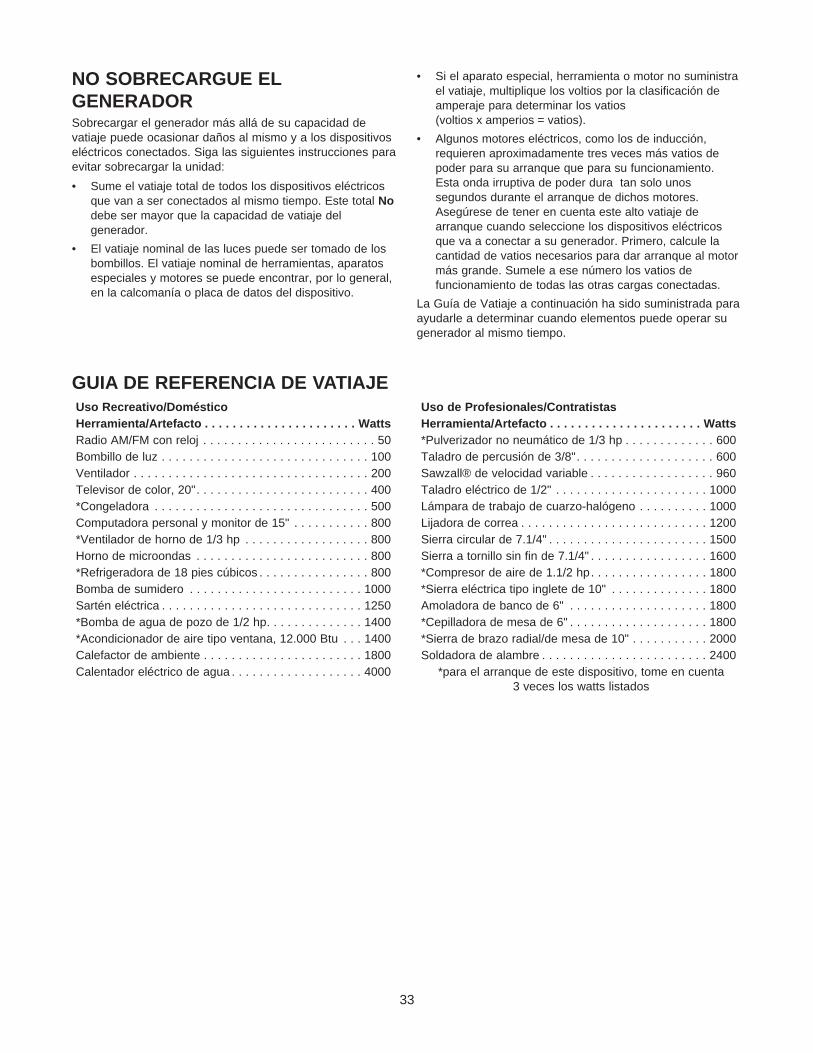
GUIA DE REFERENCIA DE VATIAJE
NO SOBRECARGUE ELGENERADORSobrecargar el generador más allá de su capacidad devatiaje puede ocasionar daños al mismo y a los dispositivoseléctricos conectados. Siga las siguientes instrucciones paraevitar sobrecargar la unidad:
• Sume el vatiaje total de todos los dispositivos eléctricosque van a ser conectados al mismo tiempo. Este total Nodebe ser mayor que la capacidad de vatiaje delgenerador.
• El vatiaje nominal de las luces puede ser tomado de losbombillos. El vatiaje nominal de herramientas, aparatosespeciales y motores se puede encontrar, por lo general,en la calcomanía o placa de datos del dispositivo.
• Si el aparato especial, herramienta o motor no suministrael vatiaje, multiplique los voltios por la clasificación deamperaje para determinar los vatios(voltios x amperios = vatios).
• Algunos motores eléctricos, como los de inducción,requieren aproximadamente tres veces más vatios depoder para su arranque que para su funcionamiento.Esta onda irruptiva de poder dura tan solo unossegundos durante el arranque de dichos motores.Asegúrese de tener en cuenta este alto vatiaje dearranque cuando seleccione los dispositivos eléctricosque va a conectar a su generador. Primero, calcule lacantidad de vatios necesarios para dar arranque al motormás grande. Sumele a ese número los vatios defuncionamiento de todas las otras cargas conectadas.
La Guía de Vatiaje a continuación ha sido suministrada paraayudarle a determinar cuando elementos puede operar sugenerador al mismo tiempo.
*para el arranque de este dispositivo, tome en cuenta3 veces los watts listados
34
ESPECIFICACIONES DELPRODUCTOEspecificaciones del GeneradorVatios de Potencia Nominal.............3,000 vatios (3.0kW)Vatios de Sobretensión Nominal ............................................3,750 vatios (3.75kW)Voltaje Nominal................................120 Voltios ACCorriente Máxima a 120 Voltios .......................................25.0 AmperiosFrecuencia Nominal .........................60 Hz a 3600 rpmFase .................................................MonofásicaPeso que Embarca ..........................110 lbs.
Especificaciones del MotorCaballos de Fuerza..........................6 a 3600 rpmDesplazamiento ...............................195 ccBujía Tipo:........................................Champion RN4C o
(0.76mm)Capacidad de Gasolina ...................1 galón americanoTipo de Aceite
Verano ......................................SAE 30 (10W-30)Invierno .....................................SAE 5W-20 o 5W-30
RECOMENDACIONES GENERALESLa garantía del generador no cubre los elementos quehayan sido sujetos al abuso o negligencia del operador.Para recibir el valor completo de la garantía, el operadordeberá mantener el generador de la forma descrita en estemanual.
Se deberán llevar a cabo algunos ajustes periódicamentepara mantener correctamente su generador.
NOTA: El inflado apropiado de la llanta la distancia queopera debe ser 15-40 PSI.
Todos los ajustes de la sección Servicio y Ajustes de estemanual deberán ser hechos por lo menos una vez en cadaestación. Cumpla con los requisitos de la tabla “Programade Mantenimiento” descrita anteriormente.
NOTA: Una vez al año deberá limpiar o reemplazar la bujíay reemplazar el filtro de aire. Una bujía nueva y un filtro deaire limpio garantizan una mezcla de combustible-aireadecuada y ayuda a que su motor funcione mejor y tengauna vida útil más prolongada.
MANTENIMIENTO DELGENERADOREl mantenimiento del generador consiste en mantener launidad limpia y seca. Opere y almacene la unidad en unambiente limpio y seco donde no vaya a estar expuesta aexcesos de polvo, suciedad, humedad o a vaporescorrosivos. Las ranuras para aire de enfriamiento delgenerador deben permanecer despejadas, sin acumulaciónde nieve, hojas u objetos extraños.
Revise frecuentemente la limpieza del generador y limpielocuando elementos como polvo, suciedad, aceite, humedad osubstancias extrañas sean visibles sobre su superficieexterior.
NOTA: No recomendamos el uso de mangueras de jardínpara limpiar el generador. El agua podría introducirse en elsistema de combustible del motor y causar problemas.Además, si el agua se introduce al generador a través delas ranuras para aire de enfriamiento, algo del agua quedaráretenida en los espacios vacíos y grietas del aislamiento deldevanado del estator y rotor. La acumulación de agua ysuciedad en los devanados internos del generadordisminuirá eventualmente la resistencia del aislamiento deestos devanados.
MANTENIMIENTOPROGRAMA DE MANTENIMIENTOSiga los intervalos horarios o de calendario, lo que ocurra primero. Se requiere de servicio con mayor frecuencia cuandoopere la unidad en las condiciones adversas descritas a continuación.
Operación de Mantenimiento Cada 5 horas 20 horas ocada estación
50 horas ocada estación
100 horas ocada estación
Revise el nivel del aceite XLimpie la pantalla del apagachispas XCambie el aceite ++ X*Proporcione servicio al cartucho deldepurador de aire X**
Reemplace la bujías X
++ Cambie el aceite después de las primeras 2 horas de operación y después cada 50 horas o cada estación.
* Cambie el aceite cada 25 horas cuando opere la unidad bajo cargas fuertes o en altas temperaturas.
** Limpie más a menudo bajo condiciones demasiado sucias o polvorientas. Reemplace las partes del depurador si estánmuy sucias.
Para Limpiar el Generador:
• Utilice un trapo húmedo para limpiar las superficiesexteriores.
• Puede usar un cepillo de cerdas suaves para retirar lasuciedad endurecida, aceite, etc.
¡PRECAUCION! Nunca inserte objetos oherramientas a través de las ranuras de enfriamientode aire, incluso si el motor no está enfuncionamiento.
• Puede usar una máquina aspiradora para eliminarsuciedad y residuos sueltos.
• Puede usar aire a baja presión (que no exceda los 25psi) para eliminar la suciedad. Inspeccione las ranuraspara aire de enfriamiento y la apertura del generador.Estas aperturas deberán mantenerse limpias ydespejadas.
¡PRECAUCION! Siempre desconecte el alambrede la bujía y manténgalo alejado de la misma cuandotrabaje en el generador.
MANTENIMIENTO DEL MOTORRevisión del Nivel de AceiteEl nivel de aceite deberá revisarse antes de cada uso o porlo menos cada 5 horas de operación. Conserve el nivel deaceite adecuado.
Cambio de Aceite del MotorCambie el aceite después de las primeras 2 horas deoperación. Cambie el aceite cada 50 horas de ese momentoen adelante. Si está utilizando su generador bajocondiciones de extrema suciedad o polvo, o en un climademasiado caliente, haga el cambio de aceite másfrecuentemente.
Cambie el aceite cuando el motor todavía se encuentrecaliente después del funcionamiento, como se indica acontinuación:
• Limpie el área alrededor de la tapa de llenado.
• Retire la tapa de llenado y drene el aceite por completoen un recipiente adecuado.
• Instale el tapón para drenaje de aceite y apriételofirmemente.
• Llene el depósito del aceite con el aceite recomendado.Vea “Antes de Poner en Marcha el Generador” en lapágina 30 para las recomendaciones del aceite.
• Instale firmemente el tapón para llenado de aceite.
• Limpie cualquier derrame de aceite.
Limpie/Reemplace la BujíaCambie la bujía cada 100 horas de operación o una vez alaño, lo que suceda primero. Esto ayudará a su motor aarrancar más fácilmente y a funcionar mejor. Reemplácelacon una bujía champion RN4C o una de tipo equivalente.
• Limpie el área alrededor de la bujía.
• Retire y revise la bujía.
• Reemplace la bujía si los electrodos están picados,quemados o si la porcelana está rota. Para sureemplazo, únicamente utilice Champion RC12YC o unade tipo equivalente.
• Revise la separación del electrodo con un calibrador dealambre y ajuste la separación a 0.030 pulgadas(0.76mm) si es necesario.
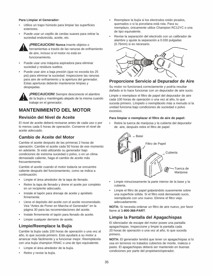
Proporcione Servicio al Depurador de AireSu motor no funcionará correctamente y podría resultardañado si lo hace funcionar con un depurador de aire sucio.
Limpie o reemplace el filtro de papel del depurador de airecada 100 horas de operación o una vez al año, lo quesuceda primero. Límpielo o reemplácelo más a menudo si launidad funciona bajo condiciones de suciedad o polvoexcesivo.
Para limpiar o reemplazar el filtro de aire de papel:
• Retire la tuerca de mariposa y la cubierta del depuradorde aire, después retire el filtro de papel.
• Limpie minuciosamente la parte interior de la base y lacubierta.
• Limpie el filtro de papel golpeándolo suavemente sobreuna superficie sólida. Si el filtro está demasiado sucio,reemplácelo con uno nuevo. Elimine el filtro viejoadecuadamente.
NOTA: Si necesita ordenar un filtro de aire nuevo, por favorllame al 1-800-366-PART.
Limpie la Pantalla del ApagachispasEl silenciador de escape del motor posee una pantallaapagachispas. Inspeccione y limpie la pantalla cada20 horas de operación o una vez al año, lo que sucedaprimero.
NOTA: El generador tendrá que tener un apagachispas si lousa en terrenos no tratados cubiertos de monte, maleza opasto. El apagachispas deberá ser mantenido en buenascondiciones por parte del propietario/operador.
35
Base
Filtro de Papel
Cubierta
Tuerca deMariposa
Limpie e inspeccione el apagachispas de la siguientemanera:
• Retire el tornillo que sujeta la pantalla del apagachispas.
• Inspeccione la pantalla y reemplácela si está rota,perforada o en general dañada. No use pantallasdefectuosas. Si la pantalla no está dañada, límpiela conun disolvente comercial.
• Vuelva a instalar la pantalla.
36
ALMACENAMIENTOGENERALIDADESEl generador deberá ser encendido al menos una vez cadasiete días y deberá dejarlo funcionar al menos durante30 minutos. Si no puede hacer esto y debe almacenar launidad por más de 30 días, use la siguiente informacióncomo guía para preparar su unidad para almacenamiento.
Instrucciones de Almacenamiento paraPeríodos Prolongados
¡ADVERTENCIA! Nunca almacene el motor concombustible en el tanque en recintos cerrados o enáreas encerradas con poca ventilación donde losvapores puedan alcanzar llamas abiertas, chispa oluz de piloto como en un horno, calentador de agua,secadora de ropa u otro aparato de gas.
Es importante evitar que se formen depósitos de goma enlas partes esenciales del sistema de combustible, como elcarburador, filtro de combustible, manguera o tanque decombustible, durante el almacenamiento. También, laexperiencia indica que los combustibles con mezclas dealcohol (llamados gasohol, etanol o metanol) pueden atraerhumedad, la cual lleva a la separación y formación deácidos durante el almacenamiento. El gas ácido puededañar el sistema de combustible de un motor durante sualmacenamiento.
Para evitar problemas del motor, el sistema de combustibledeberá desocuparse antes de un almacenamiento de30 días o más. Siga estas instrucciones:
Proteja el Sistema de Combustible
¡ADVERTENCIA! Drene el combustible dentro deun recipiente adecuado, lejos de llamas abiertas y enlugares al aire libre. Asegúrese de que el motor estéfrío. No fume.
• Retire toda la gasolina del tanque de combustible paraevitar que se formen depósitos de goma en estas partesy causen posible mal funcionamiento del motor.
• Haga funcionar el motor hasta que se detenga por lafalta de combustible.
Cambio de Aceite
Con el motor todavía caliente, drene el aceite de la caja delcigüeñal. Vuelva a llenarla con el grado de aceiterecomendado.
Aceite el Diámetro Interior del Cilindro
• Retire la bujía y rocíe aproximadamente 1 onza (30 ml)de aceite para motor limpio dentro del cilindro.
¡PRECAUCION! Evite el rociado del orificio de labujía cuando esté girando el motor lentamente.
• Cubra el orificio de la bujía con un trapo. Haga girar elmotor lentamente para distribuir el aceite.
• Instale la bujía. No conecte el alambre de la bujía.
Generador
• Limpie el generador como está descrito en la página 35(“Para Limpiar el Generador”).
• Revise que las ranuras para el aire de enfriamiento y lasaperturas del generador se encuentren abiertas ydespejadas.
Otras Sugerencias para elAlmacenamiento• No almacene gasolina de una estación a otra.
• Reemplace la caneca de gasolina si comienza aoxidarse. El óxido y/o la suciedad en la gasolina lecausará problemas.
• Si es posible, almacene su unidad en un recintoencerrado y cúbrala para protegerla del polvo y lasuciedad. ASEGURESE DE VACIAR EL TANQUE DELCOMBUSTIBLE.
• Cubra su unidad con una cubierta de protecciónadecuada que no retenga humedad.
• Almacene el generador en un área limpia y seca.
IMPORTANTE: Nunca cubra su generador cuando el motory el área del escape estén calientes.
SilenciadorApagachispas
Problema Causa Solución
El motor está funcionandopero no existe salida deAC disponible.
1. Uno de los cotacircuitos está abierto.2. Falla en el generador.
3. Mala conexión o juego de cordonesdefectuoso.
4. El dispositivo conectado está en malestado.
1. Reajuste el cortacircuito.2. Póngase en contacto con la Planta de
Servicio de Sears.3. Revise y repare.
4. Conecte otro dispositivo que esté enbuenas condiciones.
El motor funciona bien sincargas pero “funcionamal” cuando las cargasson conectadas.
1. Corto circuito en la carga conectada.2. La velocidad del motor es muy lenta.
3. El generador está sobrecargado.
4. Circuito del generador en corto.
1. Desconecte la carga eléctrica en corto.2. Póngase en contacto con la Planta de
Servicio de Sears.3. Vea “No Sobrecargue el Generador”,
página 33.4. Póngase en contacto con la Planta de
Servicio de Sears.
El motor no arranca; oarranca y funciona mal.
1. Interruptor de Marcha/Parado en“STOP”.
2. Depurador de aire sucio.
3. Sin gasolina.4. Gasolina vieja.
5. El alambre de la bujía no estáconectado.
6. Bujía en mal estado.7. Agua en la gasolina.
8. Exceso de cebado.9. Mezcla de combustible excesivamente
rica.10. Válvula de toma atascada en la posición
abierta o cerrada.11. El motor ha perdido compresión.
1. Coloque el interruptor en “RUN”(MARCHA).
2. Limpie o reemplace el depurador deaire.
3. Llene el tanque de combustible.4. Drene el tanque de gasolina; llénelo
con combustible fresco.5. Conecte el alambre a la bujía.
6. Reemplace la bujía.7. Drene el tanque de gasolina; llénelo
con combustible fresco.8. Espere 5 minutos y haga girar el motor.9. Póngase en contacto con la Planta de
Servicio de Sears.10. Póngase en contacto con la Planta de
Servicio de Sears.11. Póngase en contacto con la Planta de
Servicio de Sears.
El motor se apaga enpleno funcionamiento.
1. Sin gasolina. 1. Llene el tanque del combustible.
Al motor le hace faltapotencia.
1. La carga es muy alta.
2. Filtro de aire sucio.
1. Vea “No Sobrecargue el Generador”,página 33.
2. Reemplace el filtro de aire.
El motor “no funcionacontinuamente” o sedetiene.
Carburador con mezcla de aire-combustiblemuy rica o muy pobre.
Póngase en contacto con la Planta deServicio de Sears.
37
DIAGNÓSTICO Y REPARACIÓN DE AVERÍAS
38
GARANTIA DEL SISTEMA DE CONTROL DE EMISIONES
DECLARACION DE LA GARANTIADEL CONTROL DE EMISIONESPARA CALIFORNIA Y US EPALa Agencia de Protección Ambiental de los Estados Unidos(“EPA”), la Junta Directiva de Recursos del Aire deCalifornia (“CARB”) y Tecumseh Products Co., estáncomplacidos de explicar la Garantía de los Sistemas deControl de Emisiones Federales y en California de su nuevomotor para equipo de servicio o césped y jardín. EnCalifornia, los motores nuevos para equipo de servicio,césped y jardín deberán ser diseñados, construidos yequipados para cumplir las exigentes normas contra lacontaminación del estado. En otros estados, los motoresfabricados en el año 1997 y posteriormente deberán serdiseñados, construidos y equipados, en el momento deventa, para cumplir las regulaciones de U.S. EPA paramotores pequeños de uso fuera de carreteras. TecumsehProducts Co. garantizará el sistema de control de emisionesde su motor para equipo de servicio, césped y jardín por elperíodo de tiempo listado a continuación, con tal de quedicho equipo no haya sido sometido a abuso, abandono,modificaciones no aprobadas o mantenimiento incorrecto.
Su sistema de control de emisiones puede incluir partescomo el carburador, sistema de encendido y sistema deescape. También puede estar incluido el sistema deeliminación de compresión y otras partes relacionadas conlas emisiones.
Donde exista una condición que sea cubierta por lagarantía, Tecumseh Products Co. reparará su motor paraequipo de servicio, césped y jardín sin costo alguno parausted, incluyendo diagnóstico, partes y mano de obra.
Cubrimiento de la Garantía del Sistema deControl de Emisiones del FabricanteLos sistemas de control de emisiones de los motores paraequipo de servicio, césped y jardín de California modelo1995 y posteriores están garantizados por dos años segúnlo establecido más adelante en este documento. En otrosestados, los motores años 1997 y posteriores también estángarantizados por dos años. Si durante dicho período degarantía, cualquiera de las partes de su motor relacionadascon las emisiones es defectuosa en material o mano deobra, Tecumseh Products Co. se encargará de reparar oreemplazar dicha parte.
Responsabilidades de Garantía delPropietarioComo propietario de un motor para equipo de servicio,césped y jardín, usted es responsable por el cumplimientodel mantenimiento exigido descrito en su Manual delPropietario. Tecumseh Products Co. no negará la garantíapor la sola ausencia de los recibos o porque usted no hayasuministrado evidencia escrita del cumplimiento de todo elmantenimiento programado.
Como propietario de un motor para equipo de servicio,césped y jardín, usted debe saber que Tecumseh Products
Co. podría negarle cubrimiento de garantía si su equipo deservicio, césped y jardín, o cualquier parte, ha falladodebido a abuso, negligencia, mantenimiento incorrecto omodificaciones no aprobadas.
Usted es responsable de presentar su motor para equipo deservicio, césped o jardín a un Centro de Servicio Tecumsehautorizado (cualquier Proveedor de Servicio RegistradoTecumseh, Distribuidor de Servicio Autorizado Tecumseh oDistribuidor de Bodega Central Tecumseh) tan pronto comoel problema aparezca. Las reparaciones de garantíadeberán ser terminadas en un período de tiempo razonablesin exceder 30 días.
El Servicio de Garantía puede ser establecido poniéndoseen contacto con un Centro de Servicio AutorizadoTecumseh, o poniéndose en contacto con TecumsehProducts Co., c/o Service Manager, Engine andTransmission Group Service Division, 900 North Street,Grafton, WI 53024 - 1499. Teléfono 1-262-377-2700, oconsulte sus páginas amarillas locales bajo “Motores aGasolina” para el nombre, dirección y número telefónico deun Centro de Servicio Autorizado Tecumseh cerca a usted.
Nota ImportanteEsta declaración de garantía le explica sus derechos yobligaciones contenidos en la Garantía del Control deEmisiones (“Garantía ECS”), la cual es proporcionada porTecumseh Products Co. según las leyes de California.Tecumseh Products Co. también proporciona a loscompradores originales de motores nuevos TecumsehProducts Co., las Garantías Limitadas para Módulos deEncendido Electrónicos y Motores (“Garantía de TecumsehProducts Co.”), la cual se encuentra incluida en una hojaseparada en todos los motores nuevos de TecumsehProducts Co.. La garantía ECS se aplica únicamente alsistema de control de emisiones de su motor nuevo.Cuando exista un conflicto de términos entre la GarantíaECS y la Garantía de Tecumseh Products Co., se aplicarála garantía ECS excepto en circunstancias en que laGarantía de Tecumseh Products Co. pueda proporcionar unperíodo de garantía más prolongado. Tanto la Garantía ECScomo la Garantía de Tecumseh Products Co. describenderechos y obligaciones importantes con respecto a sumotor.
El servicio de garantía tan solo puede ser llevado a cabopor un Centro de Servicio Autorizado de TecumsehProducts Co. o por Tecumseh Products Co. en su fábrica deGrafton, Wisconsin. En el momento de solicitar el serviciode garantía, deberá presentar evidencia de la fecha deventa al comprador original. El comprador pagará los cargospor llamadas de servicio y/o por transporte de los productoshacia y desde el lugar donde la inspección y/o el trabajo deservicio es llevado a cabo. El comprador será responsablepor cualquier daño o pérdida ocurrida durante el transportede cualquier motor o parte(s) presentada para inspeccióny/o trabajo de garantía.
Si tiene preguntas con respectos y responsabilidades degarantía, deberá ponerse en contacto con TecumsehProducts Co., al 1-262-377-2700.
39
GARANTIA DEL SISTEMA DECONTROL DE EMISIONESGarantía del Sistema de Control de Emisiones (“Garantía ECS”)para motores de equipo de servicio, césped y jardín años 1995y posteriores de California (para otros estados, motoresmodelos 1997 y posteriores):
A. Aplicabilidad: Esta garantía se aplicará a los motores paraequipo de servicio, césped y jardín años 1995 y posteriores delestado de California (para otros estados, motores modelos1997 y posteriores). El período de la Garantía ECS comenzaráen la fecha en que el equipo o motor nuevo es entregado alcomprador final original y continuara por 24 mesesconsecutivos a partir de ese momento.
B. Cubrimiento General de la Garantía de Emisiones:Tecumseh Products Co., garantiza al comprador original finaldel equipo o motor nuevo, y a cada comprador subsecuente,que cada uno de sus motores para equipo de servicio, césped yjardín está:
1. Diseñado, construido y equipado para cumplir con todas lasleyes aplicables establecidas por la Junta Directiva deRecursos del Aire de acuerdo a su autoridad en losCapítulos 1 y 2, Parte 5, División 26 del Código de Salud ySeguridad, y
2. Libre de defectos en material y mano de obra que, encualquier momento durante el período de la Garantía ECS,causen que una parte garantizada relacionada con lasemisiones no sea idéntica en material con respecto a laparte descrita en la aplicación para certificación delfabricante del motor.
C. La Garantía ECS tan solo hace referencia a las partes desu motor relacionadas con emisiones de la siguiente manera:
1. Cualquier parte garantizada, relacionada con emisiones,que no esté programada para reemplazo según la secciónde mantenimiento del Manual del Propietario, estarágarantizada durante el Período de la Garantía ECS. Sicualquiera de dichas partes falla durante el Período de laGarantía ECS, la parte será reparada o reemplazada porTecumseh Products Co., de acuerdo a la Subsección 4descrita mas adelante.
2. Cualquier parte garantizada, relacionada con emisiones,que esté programada únicamente para inspección regular,según lo prescrito en el Manual del Propietario, estarágarantizada durante el Período de la Garantía ECS. Laexistencia de una afirmación en dichas instruccionesescritas con respecto a “reparar o reemplazar cuando seanecesario” no reducirá el Período de la Garantía ECS.Cualquier parte reparada o reemplazada bajo la GarantíaECS estará garantizada por el tiempo restante del Períodode la Garantía ECS.
3. Cualquier parte garantizada, relacionada con emisiones,que esté programada para reemplazo según la sección demantenimiento del Manual del Propietario, estarágarantizada por el período de tiempo anterior al primerpunto de reemplazo programado para esa parte. Si la partefalla antes del primer reemplazo programado, la parte seráreparada o reemplazada por Tecumseh Products Co., deacuerdo a la Subsección 4 descrita mas adelante. Cualquierparte relacionada con emisiones reparada o reemplazada
bajo la Garantía ECS, estará garantizada por el tiemporestante del período de la Garantía ECS antes del primerpunto de reemplazo programado para dicha parte relacionacon las emisiones.
4. La reparación o reemplazo de cualquier parte garantizadarelacionada con las emisiones bajo esta Garantía ECS serállevada a cabo sin costo alguno en un Centro de ServicioAutorizado Tecumseh.
5. Al propietario no se le cobrará por trabajo diagnóstico quelleve a la conclusión de que una parte cubierta por laGarantía ECS es en realidad defectuosa, con tal de quedicho trabajo diagnóstico sea llevado a cabo en un Centrode Servicio Autorizado Tecumseh.
6. Tecumseh Products Co. será responsable por daños a otroscomponentes del motor original o modificacionesaprobadas, causados por una falla bajo garantía de unaparte relacionada con las emisiones cubierta por la GarantíaECS.
7. Durante el período de la Garantía ECS, Tecumseh ProductsCo. mantendrá un suministro de partes garantizadasrelacionadas con las emisiones, suficientemente completocomo para satisfacer la demanda esperada para dichaspartes.
8. Cualquier repuesto de Tecumseh Products Co. autorizado oaprobado, relacionado con las emisiones, puede ser usadoen el cumplimiento de cualquier mantenimiento o reparaciónde Garantía ECS y será proporcionado sin cargo algunopara el propietario. Dicho uso no disminuirá las obligacionesde Garantía ECS de Tecumseh Products Co..
9. Las partes modificadas o adiciones no aprobadas no podránser usadas para modificar o reparar un motor de TecumsehProducts Co.. Dicha práctica cancela esta Garantía ECS yserá motivo suficiente para denegar un Reclamo deGarantía ECS. Tecumseh Products Co. no seráresponsable por fallas de partes garantizadas de un motorde Tecumseh Products Co. causadas por el uso de dichaspartes modificadas o adiciones no aprobadas.
LAS PARTES RELACIONADAS CON LASEMISIONES INCLUYEN:1. Conjunto del carburador y sus componentes internos.
a) Filtro del combustible
b) Empaques del carburador
c) Tubo de toma de admisión
2. Conjunto del depurador de aire
a) Elemento del depurador de aire
3. Sistema de encendido, incluye:
a) Bujía
b) Módulo de encendido
c) Conjunto de la rueda de volante
4. Silenciador catalítico (si está presente)
a) Empaque del silenciador (si está presente)
b) Múltiple del escape (si está presente)
5. Conjunto del respiradero de la caja del cigüeñal y suscomponentes
a) Tubo de conexión del respiradero
For in-home major brand repair service:
Call 24 hours a day, 7 days a week
1-800-4-MY-HOMESM(1-800-469-4663)
Para pedir servicio de reparación a domicilio - 1-800-676-5811
In Canada for all your service and parts needs callAu Canada por tout le service ou les pièces
For the repair or replacement parts you need:
Call 7 am - 7 pm, 7 days a week
1-800-366-PART (1-800-366-7278)
Para ordenar piezas con entrega a domicilio - 1-800-659-7084
For the location of a Sears Parts and Repair Center in your area:
Call 24 hours a day, 7 days a week
1-800-488-1222
For information on purchasing a Sears maintenance Agreementor to inquire about an existing Agreement: