1 300XAC Series Modular AC Power Source Operation Manual for Models 310XAC 320XAC 340XAC 360XAC Ver. 1.04 PART # 39101 Associated Power Technologies, Inc. Telephone: 1-909-860-1646 1142 S. Diamond Bar Blvd # 106 Fax: 1-909-860-2727 Diamond Bar, CA 91765
Transcript
1
300XAC SeriesModular AC Power Source
Operation Manual for Models
310XAC320XAC340XAC360XAC
Ver. 1.04PART # 39101
Associated Power Technologies, Inc. Telephone: 1-909-860-16461142 S. Diamond Bar Blvd # 106 Fax: 1-909-860-2727Diamond Bar, CA 91765
2
DECLARATION OF CONFORMITY
Manufacturer: Associated Power Technologies, Inc.
Address: 1142 S. Diamond Bar Blvd. #106Diamond Bar, CA 91765 USA
Product Name: 300XAC Power Source
Model Number: 310XAC, 320XAC, 340XAC, 360XAC
Conforms to the following Standards:
Safety: EN 61010-1:2001IEC 61010-01:2001
EMC: EN 61326-1:2006 Class A, EN 61000-3-2: 2006, EN 61000-3-3:1995+A1:2001+A2:2005, EN 61326-1: 2006, IEC 61000-4-2:2001, IEC 61000-4-3:2002, IEC 61000-4-4:2004, IEC 61000-4-5:2001, IEC 61000-4-6:2003, IEC 61000-4-8:1993+A1:2000,IEC 61000-4-11:2004
Supplementary Information
The product herewith complies with the requirements of the Low Voltage Directive73/23/EEC as amended by 93/68/EEC and the EMC Directive 89/336/EEC asamended by 92/31/EEC.
The CE marking has been affixed on the device according to article 10 of the EMCDirective 8/336/EEC.
The technical file and other documentation are on file with Associated Research, Inc.
______________________________
Joseph GuerrieroVice President / General Manager
Associated Power Technologies, Inc.Diamond Bar, California USAJune 21, 2010
3
Table of Contents
1. Introduction....................................................................................................71.1 Warranty .................................................................................................71.2 Glossary of Terms...................................................................................81.3 Safety Precautions ...............................................................................101.4 Service and Maintenance .....................................................................10
2. Getting Started.............................................................................................122.1 Unpacking and Inspection ....................................................................122.2 Input/Output Power Considerations......................................................12
2.2.1 Instrument Power Switch...............................................................142.2.3 Power Cable..................................................................................15
4. Programming Instructions............................................................................344.1 Powering on the Instrument..................................................................34
4.1.1 Set Screen Description..................................................................354.1.2 Security .........................................................................................364.1.3 Lock...............................................................................................374.1.4 Mem Lock......................................................................................37
4.2 System Parameters Description ...........................................................384.3 Editing System Parameters ..................................................................41
4.3.1 Editing Auto Run Mode..................................................................424.3.2 Editing Out Mode...........................................................................424.3.3 Editing Single Step (PROGRAM Mode only) .................................434.3.4 Editing Alarm .................................................................................434.3.5 Editing Contrast.............................................................................444.3.6 Editing Power Up...........................................................................444.3.7 Editing Loop Cycle (PROGRAM Mode only) .................................454.3.8 Editing V Hi-Lmt & V Lo-Lmt (MANUAL Mode only) ......................464.3.9 Editing F Hi-Lmt & F Lo-Lmt (MANUAL Mode only).......................474.3.10 Editing Start and End Angle (MANUAL Mode only) .......................484.3.11 Editing Results...............................................................................494.3.12 Editing Transient (MANUAL Mode only) ........................................494.3.13 Editing OC Fold .............................................................................504.3.14 Editing Lock...................................................................................514.3.15 Editing Mem Lock ..........................................................................514.3.16 Editing Volt Sense .........................................................................52
4
4.3.17 Editing Sync Signal........................................................................534.3.18 Editing Function (Option 08 only) ..................................................53
4.4 Using Memories and Steps (PROGRAM Mode only)............................544.4.1 Selecting a Memory.......................................................................544.4.2 Naming a Memory .........................................................................564.4.3 Selecting a Step ............................................................................57
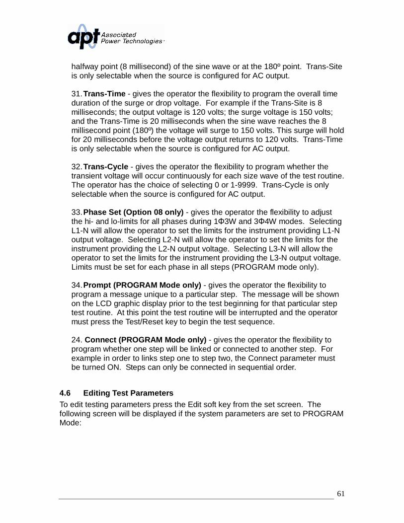
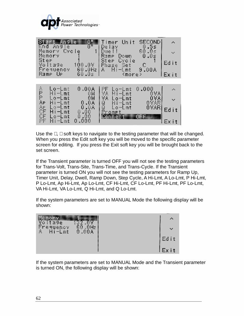
4.5 Test Parameters Description.................................................................574.6 Editing Test Parameters........................................................................61
4.7 Reviewing Test Results.........................................................................865. Test Modes ..................................................................................................87
5.1 Description of Test Modes ....................................................................875.2 Initializing a Test in PROGRAM Mode ..................................................87
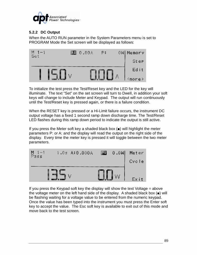
5.2.1 AC Output......................................................................................875.2.2 DC Output .....................................................................................89
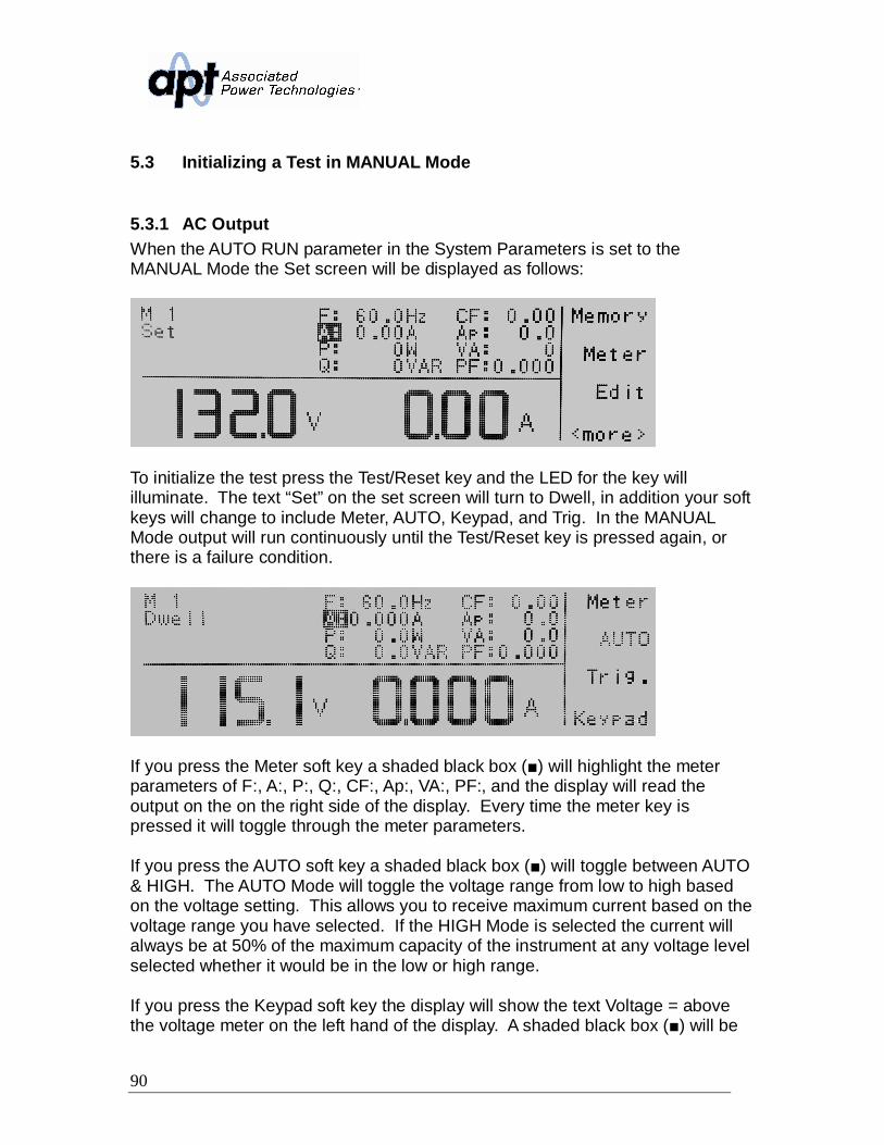
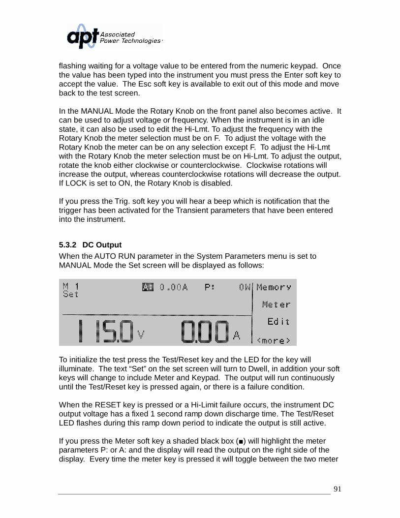
5.3 Initializing a Test in MANUAL Mode......................................................905.3.1 AC Output......................................................................................905.3.2 DC Output .....................................................................................91
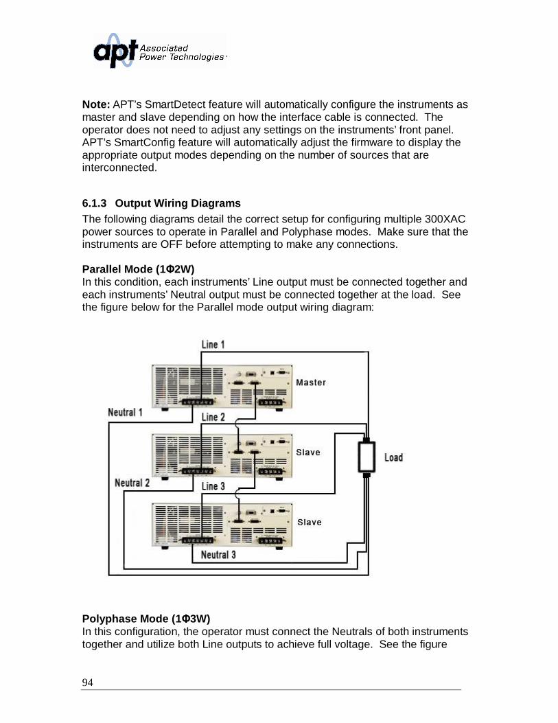
6.1 Configuring Sources for Parallel and Polyphase Operation..................936.1.1 Operating Mode Definitions ...........................................................936.1.2 Connecting the Interface Cable .....................................................936.1.3 Output Wiring Diagrams ................................................................94
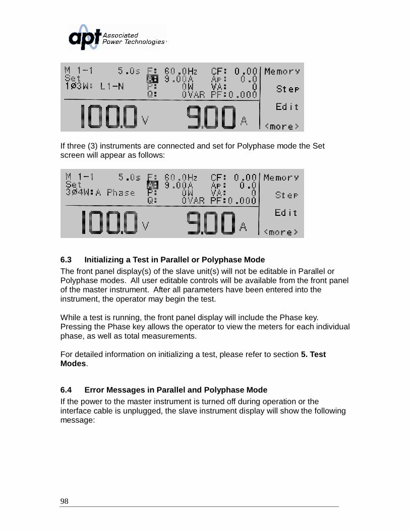
6.2 Power Up Considerations in Parallel and Polyphase Mode..................966.3 Initializing a Test in Parallel or Polyphase Mode...................................986.4 Error Messages in Parallel and Polyphase Mode .................................98
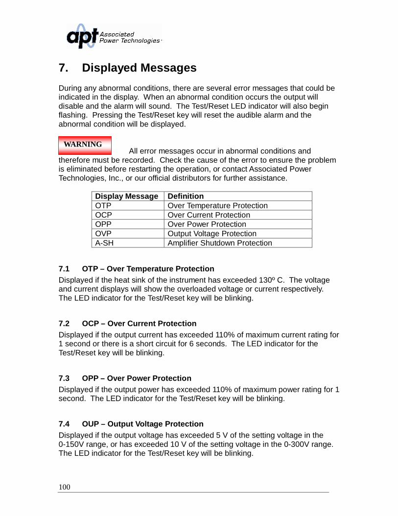
7. Displayed Messages..................................................................................1007.1 OTP – Over Temperature Protection ..................................................1007.2 OCP – Over Current Protection ..........................................................1007.3 OPP – Over Power Protection ............................................................1007.4 OUP – Output Voltage Protection .......................................................1007.5 A-SH – Amplifier Shutdown Protection ...............................................101
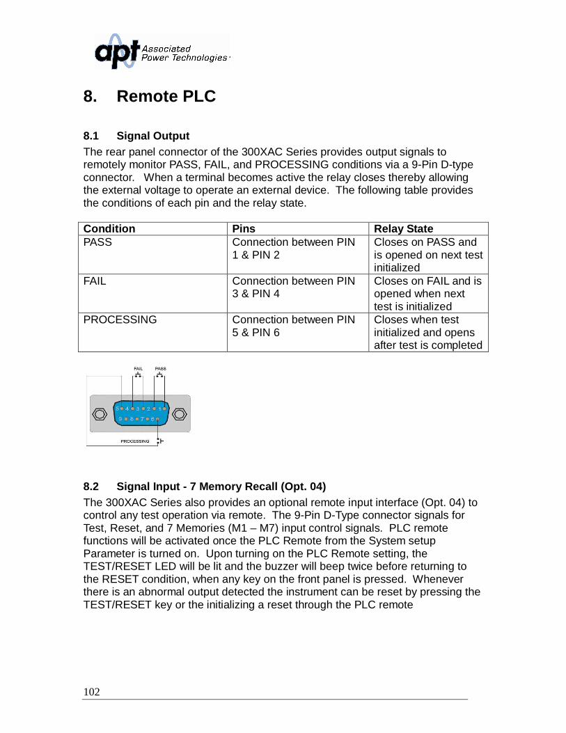
8. Remote PLC ..............................................................................................1028.1 Signal Output......................................................................................1028.2 Signal Input - 7 Memory Recall (Opt. 04)............................................102
9. Bus Remote Interface GPIB/RS-232 .........................................................1049.1 RS-232 Interface ................................................................................104
9.1.1 RS-232 Connector.......................................................................1049.1.2 Communication Port Configuration..............................................1049.1.3 Sending and Receiving Commands ............................................105
9.3 Interface Functions .............................................................................1069.4 GPIB/RS-232 Interface Command List ...............................................107
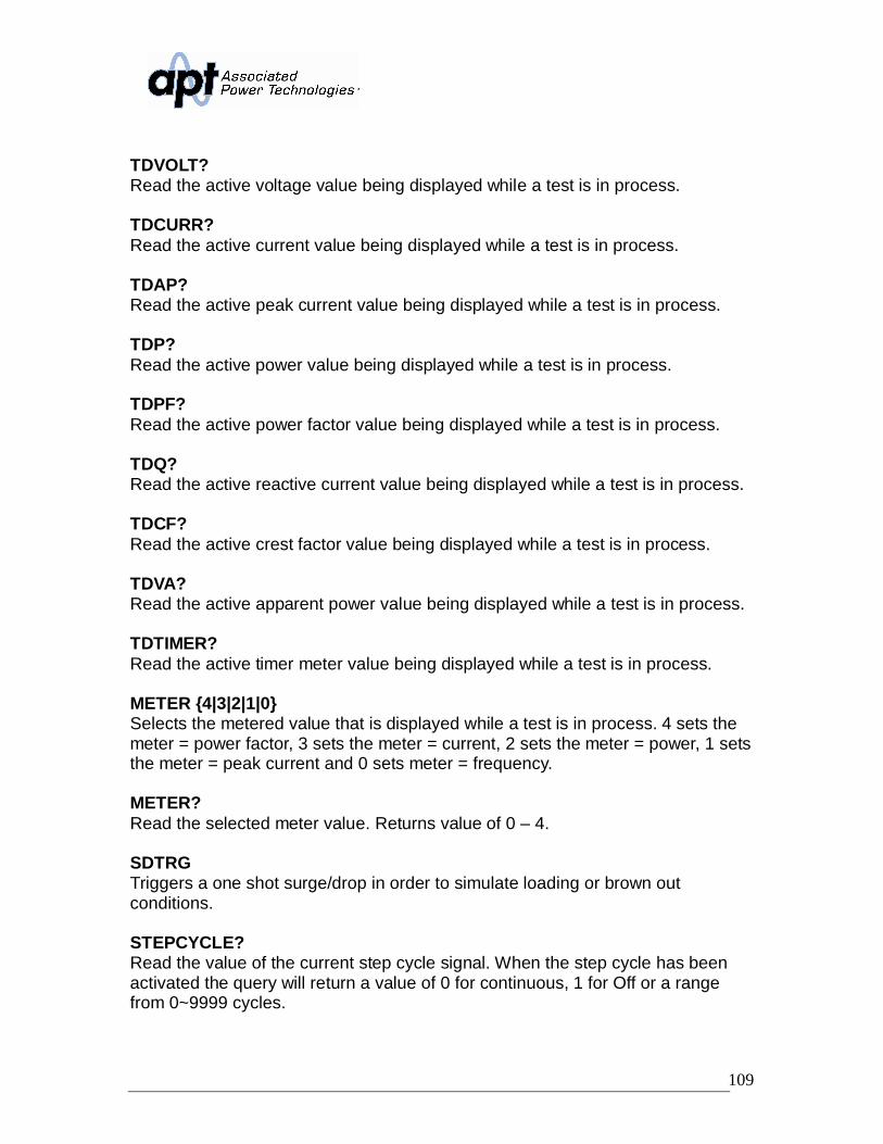
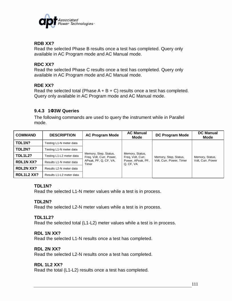
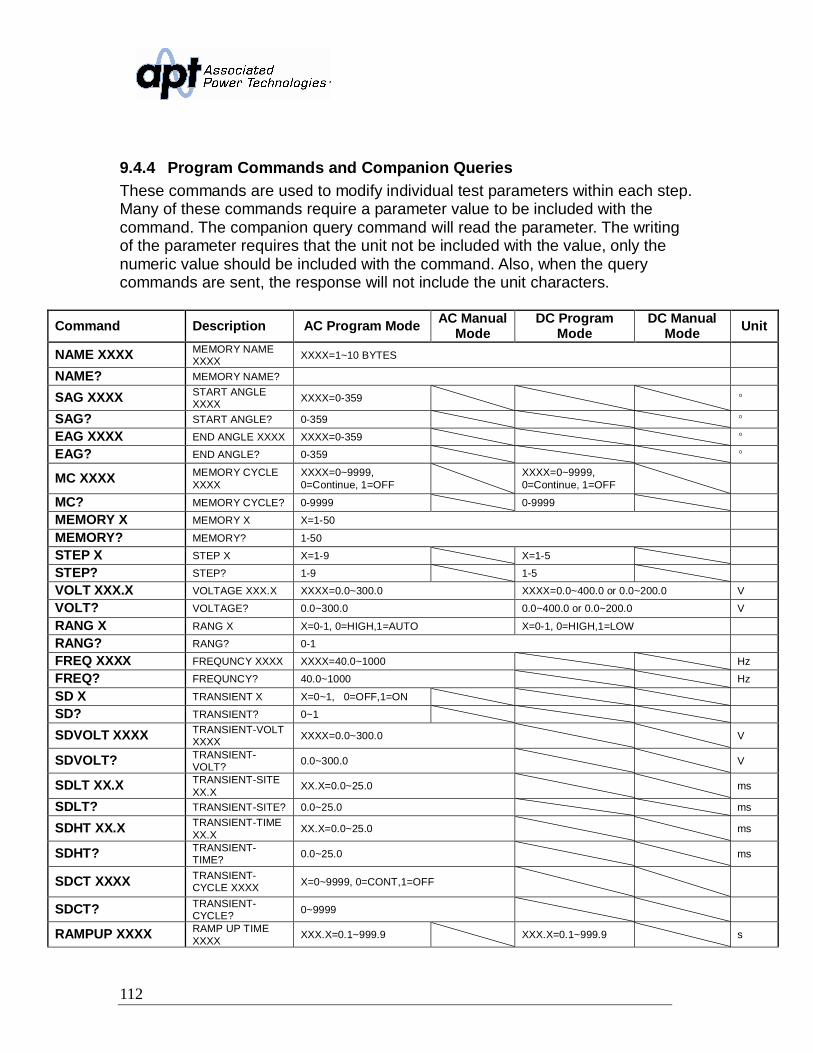
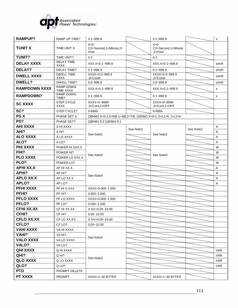
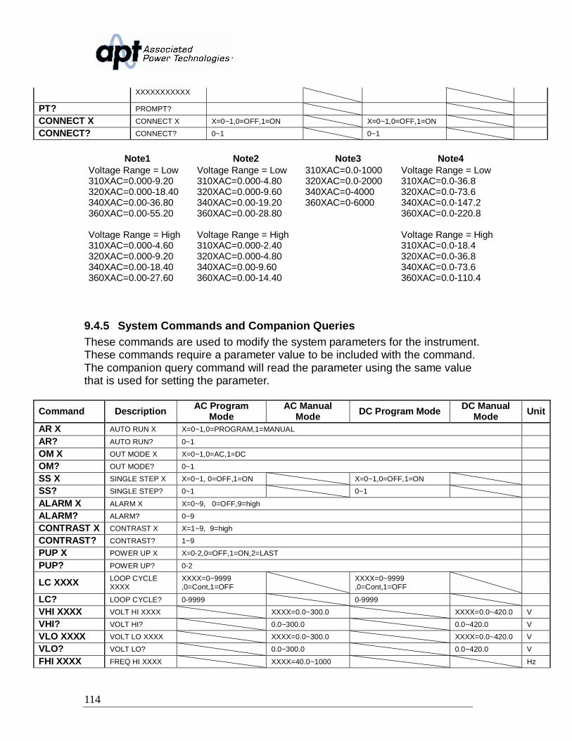
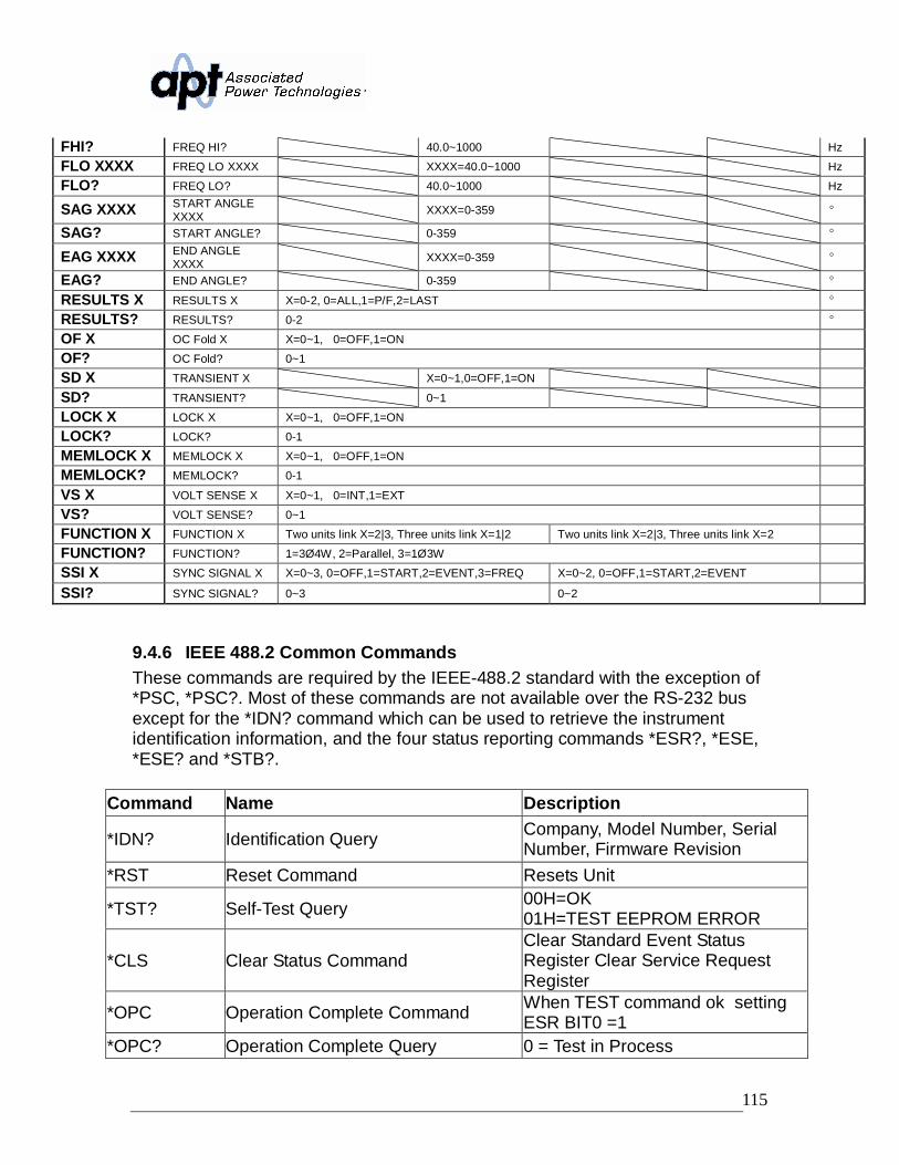
9.4.1 Basic Commands and Query Commands ...................................1079.4.2 4W Queries............................................................................. 1109.4.3 3W Queries............................................................................. 1119.4.4 Program Commands and Companion Queries............................ 1129.4.5 System Commands and Companion Queries.............................. 1149.4.6 IEEE 488.2 Common Commands................................................ 115
10. Calibration Procedure ............................................................................12010.1 Hardware Verification and Calibration Procedure ...............................12010.2 Activate Non-Calibration Mode...........................................................12010.3 Adjust Control Circuit Power Voltage..................................................12010.4 Adjust the Amplifier Inverter DC Bus Voltage......................................12110.5 Clear the Output High Frequency Noise.............................................12110.6 Adjust the “0” Volts and “110” Volts DC Offset ....................................12110.7 Adjust Wattmeter Offset......................................................................12210.8 Adjust Hardware OCP Set Point .........................................................12310.9 Exit Non-Calibration Mode..................................................................12310.10 Software Calibration Procedure ......................................................12310.11 Enter Calibration Mode ...................................................................12410.12 Calibration of Voltage 150.0V..........................................................124
6
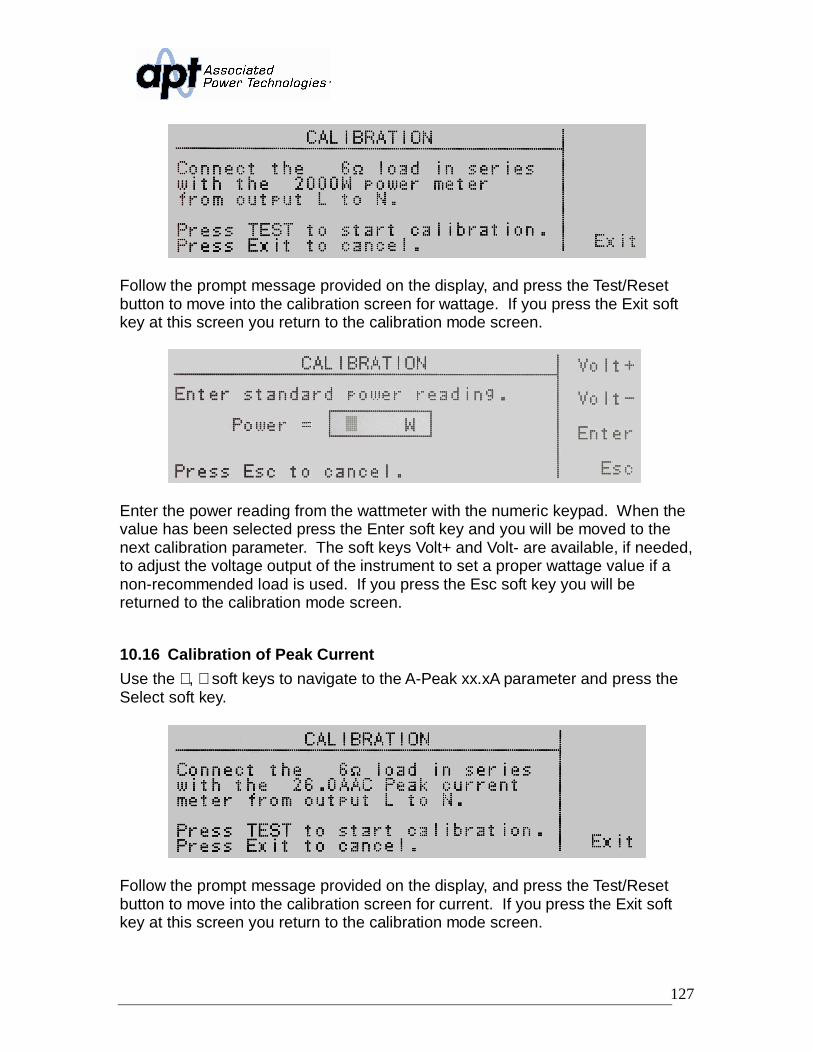
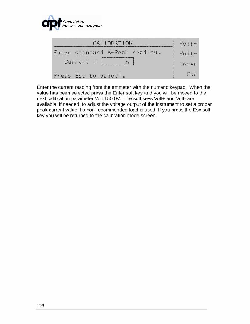
10.13 Calibration of Voltage 300.0V..........................................................12510.14 Calibration of High and Low Current Range....................................12610.15 Calibration of High and Low Power Range .....................................12610.16 Calibration of Peak Current.............................................................127
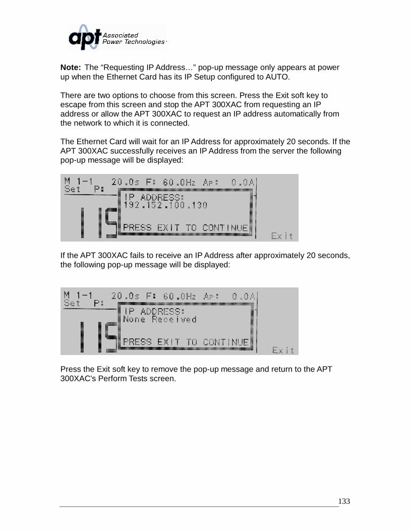
11.4.1 Ethernet Card Setup....................................................................13011.4.2 Saving New Settings ...................................................................13211.4.3 Power Up.....................................................................................13211.4.4 Ethernet Card Menu ....................................................................13411.4.5 IP Setup.......................................................................................13411.4.6 IP Address ...................................................................................13411.4.7 Gateway IP..................................................................................13511.4.8 Subnet Mask ...............................................................................13511.4.9 Device Name...............................................................................13611.4.10 MAC Address...........................................................................13711.4.11 Barcode Input...........................................................................13711.4.12 Autostart...................................................................................13911.4.13 Ethernet Card Settings Commands and Companion Queries..14011.4.14 Ethernet Card Settings Command Wait Times.........................141
11.5 Opt. 08 – Linking Card........................................................................14112. Service and Maintenance.......................................................................14213. Replacement Parts List ..........................................................................14314. Schematics Index...................................................................................146
7
1. Introduction1.1 WarrantyAssociated Power Technologies, Inc. (APT), certifies that the instrument listed inthis manual meets or exceeds published manufacturing specifications. Thisinstrument was calibrated using standards that are traceable to the NationalInstitute of Standards of Technology.
Your new instrument is warranted to be free from defects in workmanship andmaterial for a period of (2) years from date of shipment. During the warrantyperiod, you must return the instrument to Associated Power Technologies, Inc. orits branches for repair. Associated Power Technologies reserves the right to useits discretion on replacing the faulty parts or replacing the assembly or the wholeunit.
APT will void your warranty under the following states:• Operation of the instrumentation under non-normal conditions• Any non-authorized modifications, tampering or physical damage• Elimination of any connections in the earth grounding system or bypassing
any safety systems• Use of non-authorized parts in the repair of this instrument. Parts used
must be parts that are recommended by APT as an acceptable specifiedpart.
This warranty does not cover accessories not of Associated PowerTechnologies, Inc. manufacture.
Except as provided herein, APT, makes no warranties to the purchaser of thisinstrument and all other warranties, expressed or implied (including, withoutlimitation, merchantability or fitness for a particular purpose) are herebyexcluded, disclaimed and waived.
APT recommends that your instrument be calibrated on a twelve month cycle.Instruments returned to APT annually for calibration fall under our extendedwarranty which can be extended up to five years. Each year the instrument isreturned to APT in consecutive years the warranty is extended one additionalyear. This process can be repeated up to four years for a 5-Year Warranty.
Instruments returned for warranty repair within the first six months of the warrantyperiod, will have the warranty extended for one year from the date of repair at nocharge. Instruments received after the first six months can have the warrantyextended for 3 months after its original expiration date at no charge or thewarranty can be extended for a full year at the cost of an annual calibration.
8
1.2 Glossary of Terms
Alternating Current (AC) - current that reverses direction on a regular basis(usually 60 times per second in the United States). Measured in amps.
AC Power Source - An instrument that takes one AC voltage and frequency leveland converts it into another AC voltage and frequency level.
Amplifier - a circuit that boosts an input signal from one level to another.
Apparent Power - The total power generated or consumed by a device due toreal and reactive circuit components. Measured in VA (volt-amps).
Calibration - the process of comparing an unknown value with a referencestandard and reporting the results. For example: Applied = 1.30V, Indicated =1.26V (or Error= -0.04V). Calibration may include adjustment to correct anydeviation from the value of the standard.
Crest Factor - The ratio of peak current (Apeak) to RMS current (Arms).
Complex Power – the vector sum of the real and reactive power components ofa circuit. Measured in VA (volt-amps).
Direct Current (DC) - current that only flows in one direction. Direct currentcomes from a polarized source, meaning one terminal is always at a higherpotential than the other. Measured in amps.
Frequency - The number of times a waveform completes a cycle in a period oftime. Measured in hertz.
Inrush Current - A term used to describe the current needed to power a loadupon start-up. Some loads require a large/inrush starting current in order tooperate.
Linear Power Source - a power source that uses a simple amplifier to linearlyincrease the amplitude of the output waveform.
Modular - capability that allows the operator to interconnect multiple 300XACpower sources in order to increase the power output or power configurationbeyond that of a single instrument.
OC Fold - Over current fold back is a technology used in power sources thatkeeps output current constant by reducing the voltage in order to power loadsthat may have a high inrush current.
9
Parallel Mode - up to 3x 300XAC modular AC power sources can be configuredwith their outputs tied in parallel, allowing for the system to output three times asingle instrument's nominal output current rating.
PFC - Power Factor Correction is a method by which an inductance is insertedinto the input circuit of a power source to improve the power factor and overallefficiency of the system.
Phase Angle - the degree of measurement that corresponds to an ACwaveform’s amplitude. Measured from 0 – 360 degrees.
PLC - Programmable Logic Control is an automation method using relay ordigital technology.
Polyphase Mode - multiple 300XAC modular AC power sources can beconfigured to provide output voltages of up to 600VAC (output configured for
3W) or provide 3 output power (output configured for 3 4W).
Power - A generic term used to describe electrical work being done. There aremany types of power, including real power, reactive power, apparent power, andcomplex power.
Power factor - The ratio of real power (watts) to apparent power (VA). Based ona scale from 0 to 1 to determine how reactive and resistive a load is.
Reactive Power – the power absorbed by capacitive or inductive elements in acircuit. This power does no work. Measured in VAR (volt-amps reactive).
Real Power – the power that performs work in a circuit. Measured in watts.
Response Time - The time that is needed to regulate the voltage, current,frequency, and power output when a load is added to the power source.
Safety Agency Listing - A safety mark given to a product that has met stringentbenchmarks as classified by the authorized agency.
SmartConfig - this feature allows the operator to change the output of AC powersources in a linked system from Parallel to Polyphase modes with a simplebutton push. Changing internal cables or dip switches is not required.
SmartDetect - this feature automatically assigns the appropriate master/slavedesignation for each AC power source in a linked system without the need for theoperator to reconfigure internal hardware.
Steady State Current - A term used to describe the current when the load is
10
running nominally after the inrush current.
Switching Power Source - A power source that uses switching technology(integrated circuits and components) in order to generate the output waveform.
Total Harmonic Distortion (THD) - A percentage that is used to identify thedegree of the noise/unclean signal in a power source’s output waveform.
Transient - a momentary change (spike or dip) in a voltage or current waveformthat can affect the performance of the DUT.
Verification - comparison of measured results against a specification, usually themanufacturer's published performance figures for the product (e.g. Error = -0.04V, Spec = ±0.03V, result: "FAIL").
Voltage - The amount of force that is needed to move current from point to point.Measured in volts.
1.3 Safety PrecautionsThis product and its related documentation must be reviewed for familiarizationwith safety markings and instructions before operation.
To prevent accidental injury or death, these safety procedures must be strictlyobserved when handling and using the test instrument.
1.4 Service and Maintenance
User ServiceTo prevent electric shock do not remove the instrument cover. There are no userserviceable parts inside. Routine maintenance or cleaning of internal parts is notnecessary. Any external cleaning should be done with a clean dry or slightlydamp cloth. Avoid the use of cleaning agents or chemicals to prevent any foreignliquid from entering the cabinet through ventilation holes or damaging controlsand switches, also some chemicals may damage plastic parts or lettering. Anyreplacement cables and high voltage components should be acquired directlyfrom APT or its distributors.
Service IntervalThe instrument must be returned at least once a year to an APT authorizedservice center for calibration and inspection of safety related components. APTwill not be held liable for injuries suffered if the instrument is not properlymaintained and safety checked annually.
11
User ModificationsUnauthorized user modifications will void your warranty. APT will not beresponsible for any injuries sustained due to unauthorized equipmentmodifications or use of parts not specified by APT. Instruments returned to APTwith unsafe modifications will be returned to their original operating condition atthe customer’s expense.
12
2. Getting StartedThis section contains information for the unpacking, inspection, preparation foruse and storage of your APT product.
2.1 Unpacking and InspectionYour instrument was shipped in a protective shipping carton designed to protectthe instrument through the shipping process. If the shipping carton is damaged,inspect the contents for visible damage such as dents, scratches, or brokendisplay. If the instrument is damaged, notify the carrier and APT’s customersupport department. Please save the shipping carton and packing material forthe carrier’s inspection. Our customer support department will assist you in therepair or replacement of your instrument. Please do not return your productwithout first notifying us. Please retain all of the original packaging material.
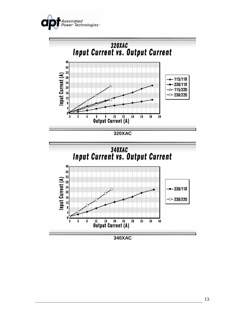
2.2 Input/Output Power ConsiderationsSpecial care should be taken when making connections to the input and outputterminal blocks located on the rear panel of the 300XAC. Ensure that theappropriate wire gauges are used to assemble a satisfactory line cord. Failure toassemble a quality line cord could result in fire or personal injury. Refer to thefollowing table for input/output current requirements:
310XAC
13
320XAC
340XAC
14
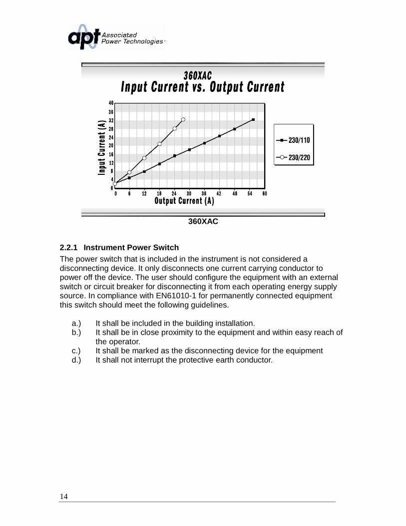
360XAC
2.2.1 Instrument Power SwitchThe power switch that is included in the instrument is not considered adisconnecting device. It only disconnects one current carrying conductor topower off the device. The user should configure the equipment with an externalswitch or circuit breaker for disconnecting it from each operating energy supplysource. In compliance with EN61010-1 for permanently connected equipmentthis switch should meet the following guidelines.
a.) It shall be included in the building installation.b.) It shall be in close proximity to the equipment and within easy reach of
the operator.c.) It shall be marked as the disconnecting device for the equipmentd.) It shall not interrupt the protective earth conductor.
15
2.2.2 Selecting the Appropriate Wire GaugeBelow is a table which provides recommended appropriate wire gauges for the300XAC.
Before connecting power to this instrument, the protectiveground (earth) terminals of this instrument must be connected to the protectiveconductor of the line (mains) power cord. The main plug shall only be inserted ina socket outlet (receptacle) provided with a protective ground (earth) contact.This protective ground (earth) must not be defeated by the use of an extensioncord without a protective conductor (grounding).
360XAC Power Cable ConsiderationsThe 360XAC can be powered with several different input power configurations.Refer to the diagram below for connecting a single phase, 3 phase wye, and 3phase delta power source to the instrument:
Original PackagingPlease retain all original packaging materials that you originally received. If you
17
are returning your instrument to us for servicing please repackage the instrumentin its original container. Please enclose the instrument with all options,accessories and test leads. Also, please mark the container “FRAGILE” to insureproper handling. All returns must be accompanied by a return materialauthorization (RMA) number which is provided by the customer supportdepartment. Failure to ship your instrument without a RMA number will result inadditional fees for handling and storage.
Other PackagingIf you have discarded the container please follow these guidelines:
• A wooden skid must be used.• The instrument needs to be securely strapped to the skid.• A protective double wall container must be placed over the instrument and
also secured to the side.• Mark the container “FRAGILE” to ensure proper handling.
For all other models, if you do not have the original packaging materials, pleasefollow these guidelines:
• Wrap the instrument in a bubble pack or similar foam. Enclose the sameinformation as above.
• Use a strong double-wall container that is made for shippinginstrumentation. A 350 lbs. test material is adequate.
• Use a layer of shock-absorbing material 70 – 100 mm (3 to 4 inch) thickaround all sides of the instrument. Protect the control panel withcardboard.
• Seal the container securely.• Mark the container “FRAGILE” to insure proper handling.
APT will not be responsible for any repair costs associated with shipping damageas a result of improper packaging. The customer is responsible for providingadequate shipping insurance coverage while shipping an instrument in the eventof loss or damage while in transit.
18
3. Specifications and Controls
3.1 Specifications
INPUT 310XAC 320XAC 340XAC 360XACPhase or 3
Voltage 100 - 240 V ± 10% 200 - 240 V ±10%
: 200 - 240 V ± 10%3W: 200 - 240 V ±
10% 3 4W: 346 - 416V ± 10%
Frequency 47 - 63 HzOUTPUT ACVOLTAGEVoltage 0 - 300 V 5 - 300 VPower 1 KVA 2 KVA 4 KVA 6 KVAMax Current 0 - 150 V L 9.2 A @ 110 V 18.4 A @ 110 V 36.8 A @ 110 V 55.2 A @ 110 VLine to Neutral 0 - 300 V H 4.6 A @ 220 V 9.2 A @ 220 V 18.4 A @ 220 V 27.6 A @ 220 VInrush Current(peak) 0 - 150 V L 36.8 A 73.6 A 147.2 A 220.8 A
0 - 300 V H 18.4 A 36.8 A 73.6 A 110.4 AFrequency 40.0 - 1000 HzPhase (Linking Available for 1 3W or 3 4W)
THD
<1% (Resistive Load) at output voltage 80 - 140 V & 160 - 280 V, <1.5% (ResistiveLoad) at 501-1000Hz and output voltage within the 100~140Vac at Low Range or the
160~280Vac at High Range.Crest Factor 3Line Regulation ± 0.1 VLoad Regulation ± 0.5 VDC Offset ± 5 mVOUTPUT DCVOLTAGEVoltage 0 - 420 V 5 - 420 VPower 1000 W 2000 W 4000 W 6000 WMax Current 0 - 210 V L 4.8 A 9.6 A 19.2 A 28.8 A
0 - 420 V H 2.4 A 4.8 A 9.6 A 14.4 ARipple & Noise (rms) 0 - 210 V L < 500 mV < 720 mV
0 - 420 V H < 800 mV <1100 mVRipple & Noise (p-p) < 3.0 Vp-p < 4.0 Vp-pMEASUREMENTAC 310XAC 320XAC 340XAC 360XACVoltage Range 0.0 - 400.0 V
Resolution 0.1 VAccuracy ± (1% of reading + 2 counts) > 5 V ± (1% of reading + 5 counts) > 5 V
Frequency Range 0.0 - 1000 HzResolution 0.1 HzAccuracy L ± 0.1 Hz @ 0.0 - 500 Hz
H ± 0.2 Hz @ 501 - 1000 Hz
19
MEASUREMENTAC Cont. 310XAC 320XAC 340XAC 360XAC
Current (rms) Range L 0.005 A - 1.200 A0.005A - 2.400
A x xH 1.00 A 13.00A 2.00 A - 26.00 A 0.05 A - 52.00 A 0.05 A - 78.00 A
Current (peak) Range 0.0 A- 38.0 A 0.0 A - 76.0 A 0.0 A - 152.0 A 0.0A - 228 AResolution 0.1 AAccuracy ± (1% of reading + 5 counts)
Power (W) Range L 0.0 W - 120.0 W 0.0 W - 240.0 W x xH 100 W - 1300 W 200 W - 2600 W 0 W - 5200 W 0 W - 7800 W
Resolution L 0.1 W x xH 1 W
Accuracy L± (2% of reading + 15 counts) at PF
0.2 x x
H
± (2% of reading +5 counts) at PF 0.2 ± (2% of reading + 5 counts) at PF 0.2
Power Apparent(VA) Range L 0.0 VA - 120.0 VA
0.0 VA - 240.0VA x x
H 100 VA - 1300 VA200 VA - 2600
VA 0 VA - 5200 VA 0 VA - 7800 VAResolution L 0.1 VA x x
H 1 VAAccuracy V x A, Calculated Value
Power Reactive (Q) Range L0.00 VAR - 120.0
VAR0.0 VAR - 240.0
VAR x x
H 0 VAR - 1300 VAR0 VAR - 2600
VAR0 VAR - 5200
VAR 0 VAR - 7800 VARResolution L 0.1 VAR x x
H 1 VARAccuracy (va)² - (w)², calculated value
Power Factor Range 0 - 1.000Resolution 0.001Accuracy W/VA, Calcualted value and displayed to 3 significant digits
Crest Factor Range 0 - 10.00Resolution 0.01Accuracy Ap/A, Calculated value and displayed to 2 significant digits
MEASUREMENTDC 310XAC 320XAC 340XAC 360XACVoltage Range 0.0 - 420.0 V 5.0 - 420.0 V
Resolution 0.1 VAccuracy ± (1% of reading + 2 counts) ± (1% of reading + 5 counts)
Current Range L 0.010 A - 1.200A0.010 A - 2.400
A x x
20
MEASUREMENTDC Cont. 310XAC 320XAC 340XAC 360XAC
H 1.00 A - 13.00 A 2.00 A - 26.00 A 0.05 A - 52.00 A 0.05 A - 78.00 AResolution L 0.001 A
H 0.01 AAccuracy L ± (1% of reading + 5 counts)
H ± (1% of reading + 5 counts)Power Range L 0.0 W - 120.0 W 0.0 W - 240.0 W x x
H 100 W - 1300 W 200 W - 2600 W 0 W - 5200 W 0 W - 7800 WResolution L 0.1 W x x
H 1 WAccuracy L ± (2% of reading + 5 counts) x x
H ± (2% of reading + 5 counts)TEST SETTING PARAMETERS 310XAC 320XAC 340XAC 360XACMemory Range 1 - 50 LocationsMemory Cycle 0 -9999, 0 = Cont., 1 = OFFStep AC Range 1 - 9
DC Range 1-5Step Cycle 0 - 9999, 0 = Cont., 1 = OFFVoltage Output AC, DCVoltage Range AC 0.0 - 300.0 V High/Auto Mode 5.0 - 300.0
DC 0.0 - 420.0 V High/Low Range 5.0 - 420.0Resolution 0.1 VAccuracy ± (1% of reading + 2 counts) ± (1% of reading + 5 counts) > 5 V
Voltage Hi-Lmt AC 0.0 V - 300 V 5.0 V - 300 VDC 0.0 V - 420 V 5.0 V - 420 V
Voltage Lo-Lmt AC 0.0 V - 300 V 5.0 V - 300 VDC 0.0 V - 420 V 5.0 V - 420 V
Frequency Hi-Lmt Range 40.0 - 1000 HzFrequency Lo-Lmt Range 40.0 - 1000 HzFrequency Resolution 0.1 Hz @ 40.0 - 99.9 Hz, 1 Hz @ 100 - 1000 Hz
Accuracy ±0.03%
Current (rms) Hi-Lmt Range AC0.005 A – 9.2 A,0 = OFF
0.005 A - 18.4A, 0 = OFF
0.05 A - 36.8 A,0 = OFF
0.05 A - 55.2 A, 00 = OFF
DC 0.01 A - 4.60 A 0.01 A - 9.60 A 0.10 A - 18.40 A 0.10 A - 27.6 ACurrent (rms) Lo-Lmt AC 0.005 A - 9.2 A 0.005 A - 18.4 A 0.05 A - 36.8 A 0.05 A - 55.2 A
DC 0.01 A - 4.60 A 0.01 A - 9.60 A 0.10 A - 18.40 A 0.10 A - 27.6 ACurrent (rms) Resolution 0.01 Amp
Accuracy ± (2.0% of setting + 2 counts)Current (peak) Hi-Lmt
0.0 A- 38.0 A,0 = OFF
0.0 A - 76.0 A,0 = OFF
0.0 A - 152.0 A,0 = OFF
0.0A - 228 A,0 = OFF
Current (peak) Lo-Lmt 0.0 A- 38.0 A 0.0 A - 76.0 A 0.0 A - 152.0 A 0.0A - 228 A
Power Hi-Lmt0.0 W - 1300 W,0 = OFF
0.0 W - 2600 W,0 = OFF
0 W - 5200 W,0 = OFF
0 W - 7800 W,0 = OFF
21
TEST SETTING PARAMETERS Cont. 310XAC 320XAC 340XAC 360XAC
Power Lo-Lmt0.0 W - 1300 W,0 = OFF
0.0 W - 2600 W,0 = OFF
0.0 W - 5200 W,0 = OFF
0.0 W - 7800 W, 0 =OFF
Power Apparent Hi-Lmt
0.0 VA - 1300 VA,0 = OFF
0.0 VA - 2600VA, 0 = OFF
0 VA - 5200 VA,0 = OFF
0 VA - 7800 VA,0 = OFF
Power Apparent Lo-Lmt
0.0 VA - 1300 VA,0 = OFF
0.0 VA - 2600VA, 0 = OFF
0 VA - 5200 VA,0 = OFF
0 VA - 7800 VA,0 = OFF
Power Reactive Hi-Lmt
0.0 VAR - 1300VAR, 0 = OFF
0.0 VAR - 2600VAR, 0 = OFF
0 VAR - 5200VAR, 0 = OFF
0 VAR - 7800 VAR,0 = OFF
Power Reactive Lo-Lmt
0.0 VAR - 1300VAR, 0 = OFF
0.0 VAR - 2600VAR, 0 = OFF
0 VAR - 5200VAR, 0 = OFF
0 VA - 7800 VA,0 = OFF
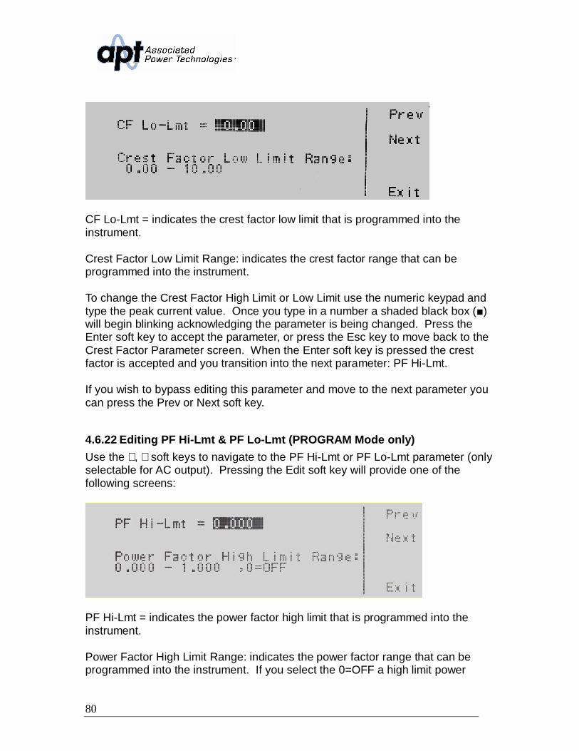
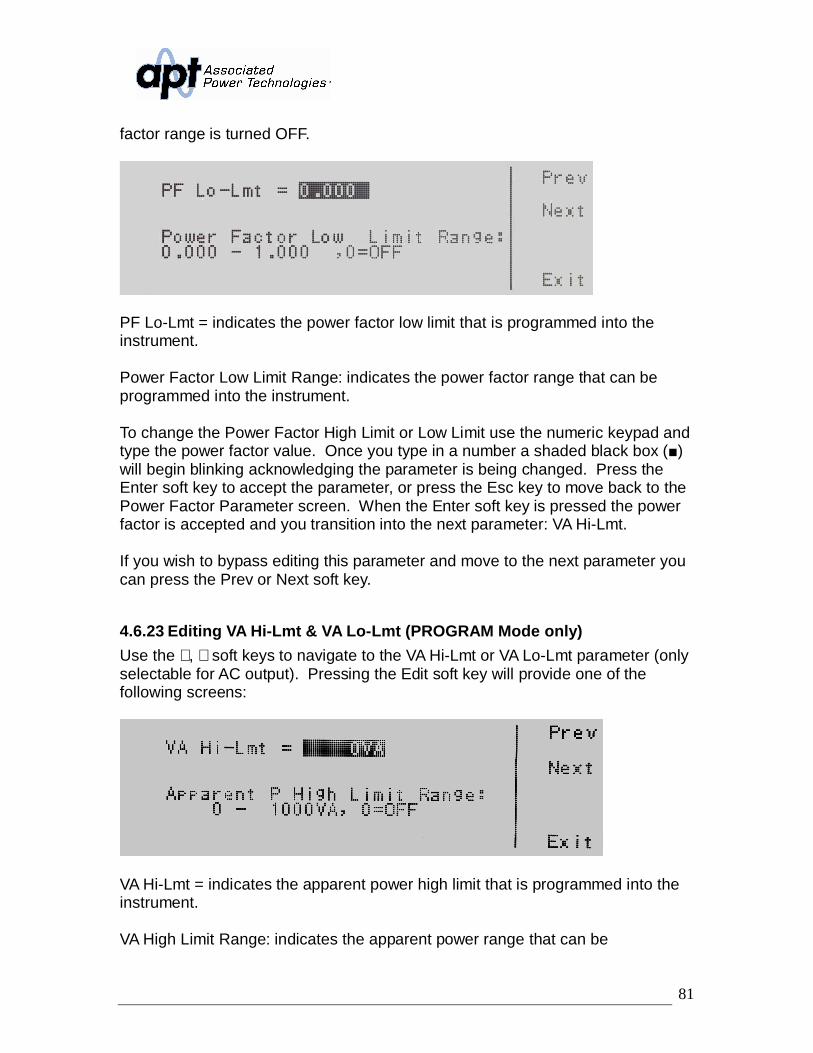
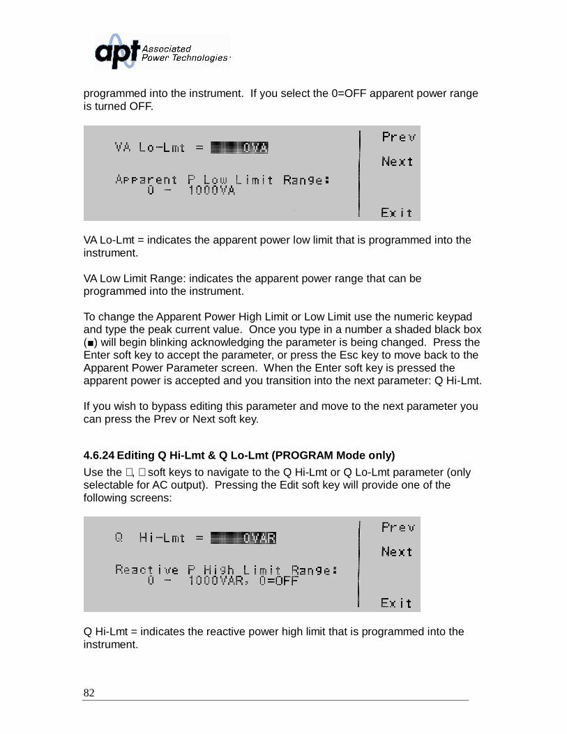
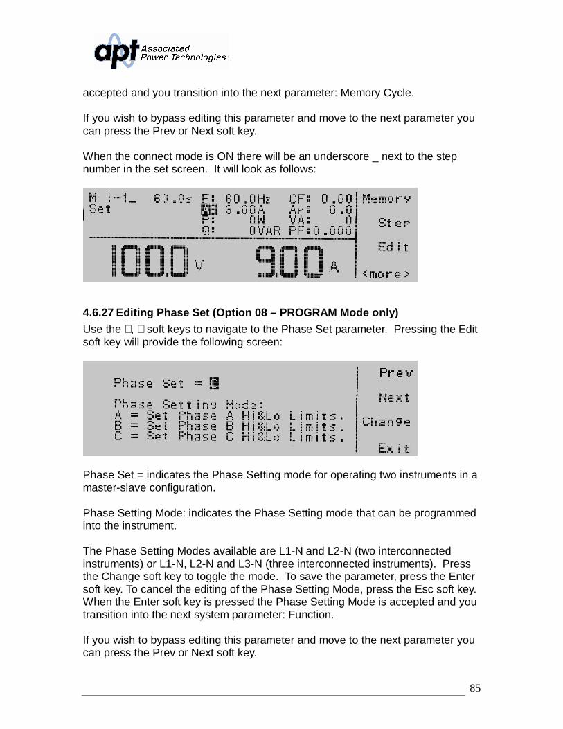
Power Factor Hi-Lmt 0.000 - 1.000, 0 = OFFPower Factor Lo-Lmt 0.000 - 1.000Crest Factor Hi-Lmt 0.00 - 10.00, 0 = OFFCrest Factor Lo-Lmt 0.00 - 10.00Timer Unit Second, Minute, HourRamp Up Range AC 0.00 - 999.9
Accuracy ±1% (45 Hz - 65 Hz)Connect ON, OFFTransient ON, OFF (Only 40 Hz - 70 Hz is available)SD-Volt 0.0 V - 300.0 VSD-Site 0.0 - 25.0 msecSD-Time 0.5 - 999.9 msec (Trans-Cycle =ON) & 1 - 99 msec (Trans-Cycle = OFF)Trans-Cycle ON, OFF (Each cycle one surge/drop is created on waveform) 0-9999, 0=OFF
22
SYSTEMPARAMETERS 310XAC 320XAC 340XAC 360XACAuto Run Program, ManualOutput Mode Manual AC, DCSingle Step Program ON, OFFAlarm 0 - 9, 0 = OFF, 9 = HighContrast 1 - 9, 9 = HighPower Up ON, OFF, LASTLoop Cycle Program 0 - 9999, 0 = Cont., 1 = OFFResults LAST, P/F, ALLOC Fold ON, OFFTransient Manual ON, OFFLock ON, OFFMem Lock ON, OFFVolt Sense INT, EXTSynch Signal START, Freq, EVENT, OFF, 5 V DC SignalLinking AUTO DETECT (Parallel, 1 3W, 3 4W)Re-Config YES, NOAddress IP, GPIB, RS-485GENERAL 310XAC 320XAC 340XAC 360XACEnhanced Over Load Capacity Over current 110% can hold for 1000 ms without protectionOperation KeyFeature Soft key, Numeric Key, Rotary KnobRemote OutputSignal Output (Pass, Fail, Test in Process)Calibration Front PanelKey Lockout Soft Key & Password ProtectedSynch Output Signal 5 V DCGraphic Display 260 x 64 Mongraphic, LCDInterface USB/RS-232Barcoding Barcode CapableProtection Circuit Over Current, Over Temperature, Over Power, Over VoltageFan Temperature ControlledRear Output Terminal BlockRack Mount Handles Standard No Caster WheelsPFC 97% at Full LoadEfficiency 75% at Full Load 80% at Full LoadCE Mark YesParallel/Poly-Phase Output Multiple Source Linking: L1 - N & L2 - N 1 3W (180º), A/B/C 3 4W (120º)OperationEnvironment 0 - 40ºC / 20 - 80% RH
Dimensions 430 (W) x 133.5 (H) x 530 (D) mm430 (W) x 267(H) x 500 (D) mm
430 (W) x 400.5 (H) x500 (D) mm
Net Weight 21 Kg 22 Kg 37 kg 53 Kg
23
OPTIONS 310XAC 320XAC 340XAC 360XACGrounded Neutral Option 2 All ModelsGPIB Interface Option 3 All Models7 Memory Remote Option 4 Input (Test, Reset, Recall Memory 1 - 7)Ethernet/RS-232/Barcode Option 5 All ModelsLinking Card Option 8 All ModelsLINKING PARALLEL AC OUTPUT
2W 310XAC 320XAC 340XAC 360XACLinked Units 2 - 3 Units, 1 2W (L1 - N )Voltage Phase 0 - 300 V 5 - 300 VPower # Units 2 1.6 KVA 3.2 KVA 6.4 KVA 9.6 KVAMax 3 2.4 KVA 4.8 KVA 9.6 KVA 14.4 KVA
Max Current 5 - 150 V L(2)14.72 A @ > 20 V
and < 120 V29.44 A @ > 20 V
and < 120 V58.88 A @ > 20 V
and < 120 V88.32 A @ > 20 V
and < 120 V
L(3)22.08 A @ > 20 V
and < 120 V44.16 A @ > 20 V
and < 120 V88.20 A @ > 20 V
and < 120 V132.48 A @ > 20 V
and < 120 V
5 - 300 V H(2)7.36 A @ > 20 V
and < 240 V14.72 A @ > 20 V
and < 240 V29.44 A @ > 20 V
and < 240 V44.16 A @ > 20 V
and < 240 V
Line H(3)11.04 A @ > 20 V
and < 240 V22.08 A @ > 20 V
and < 240 V44.16 A @ > 20 V
and < 240 V66.24 A @ > 20 V
and < 240 VLINKING POLY-PHASE AC OUTPUT
3W 310XAC 320XAC 340XAC 360XACLinked Units 2 Units @ 180º, 1 3W (L1-L2 - N)Voltage Phase 0 - 600 V 10 - 600 V
Line 0 - 300 V 5 - 300 VPower Max 2 KVA 4 KVA 8 KVA 12 KVA
Max Current Line 0 - 300 VL(2) 9.2 A @ 220 V 18.4 A @ 220 V 36.8 A @ 220 V 55.2 A @ 220 V
Phase 0 - 600 VH(2) 4.6 A @ 440 V 9.2 A @ 440 V 18.4 A @ 440 V 27.6 A @ 440 V
LINKING POLY-PHASE AC OUTPUT4W 310XAC 320XAC 340XAC 360XAC
Linked Units 3 Units @ 120º, 3 4W (L1-L2-L3 - N)Voltage Phase 0 - 300 V 5 - 300 V
Line 0 - 520 V 5 - 520 VPower Max 3 KVA 6 KVA 12 KVA 18 KVAMax Current 0 - 150 V L 9.2 A @ 110 V 18.4 A @ 110 V 36.8 A @ 110 V 55.2 A @ 110 VPhase 0 - 300 V H 4.6 A @ 220 V 9.2 A @ 220 V 18.4 A @ 220 V 27.6 A @220 V
Max Current 0 - 260 V L 5.31 A @ 190.5 V10.62 A @
190.5 V21.24 A @ 190.5
V 31.87 A @ 190.5 VLine 0 - 520 V H 2.65 A @ 381 V 5.31 A @ 381 V 10.62 A @ 381 V 15.93 A @ 381 V
24
LINKING PARALLEL DC OUTPUT2W 310XAC 320XAC 340XAC 360XAC
Linked Units 2 - 3 Units, 1 2W (L1 - N )Voltage Line 0 - 420 V 5 - 420 VPower # Units 2 1.6 KVA 3.2 KVA 6.4 KVA 9.6 KVAMax 3 2.4 KVA 4.8 KVA 9.6 KVA 14.4 KVAMax Current 5 - 210 V L(2) 7.68 A @ 210 V 15.36 A @ 210 V 30.72 A @ 210 V 46.08 A @ 210 V
L(3) 11.52 A @ 210 V 23.04 A @ 210 V 46.08 A @ 210 V 69.12 A @ 210 V5 - 420 V H(2) 3.84 A @ 420 V 7.68 A @ 420 V 15.36 A @ 420 V 23.04 A @ 420 V
Line H(3) 5.76 A @ 420 V 11.52 A @ 420 V 23.04 A @ 420 V 34.56 A @ 420 VMEASUREMENT (Total)*LINKING PARALLEL 1 2W 310XAC 320XAC 340XAC 360XACVoltage Range 0.0 - 400.0 V
Resolution 0.1 VAccuracy ± (1% of reading + 2 counts) > 5 V ± (1% of reading + 5 counts) > 5 V
Frequency Range 0.0 - 1000.0 HzResolution 0.1 HzAccuracy L ± 0.1 Hz @ 0.0 - 500 Hz
H ± 0.2 Hz @ 501 - 1000 HzCurrent (rms) Range 2 0.00 A - 26.00 A 0.00 A - 52.00 A 0.00 A - 104.0 A 0.00 A - 156.0 A
3 0.00 A - 39.00 A 0.00 A - 78.00 A 0.00 A - 156.0 A 0.00 A - 234.0 AResolution 0.01 A 0.1A <= 99.99A, 0.01A > 100.0A
Accuracy L
± (1.5% of reading + 15 counts) x # ofLinked Units @ 40 - 70 Hz & Current
is > 1.00 A
H
± (1.5% of reading + 15 counts) x # ofLinked Units @ 70.1 - 1000 Hz &
Current is > 5.00 A
± (1.5% ofreading +
15counts)× LinkUnits at 40 -70Hz, and
current(r.m.s) >2.00A
± (1.5% ofreading +
15counts)× LinkUnits at 70.1 -1000Hz, and
current(r.m.s) >10.00A
± (1.5% of reading +15counts)× Link Units at
40 - 70Hz, andcurrent(r.m.s) > 3.00A± (1.5% of reading +
15counts)× Link Units at70.1 - 1000Hz, and
current(r.m.s) > 15.00A
Power (W) Range 2 0 W - 2600 W 0 W - 5200 W 0 W -10400 W 0 W - 15600 W3 0 W - 3900 W 0 W - 7800 W 0 W - 15600 W 0 W - 23400 W
Resolution 1 W
Accuracy± (2% of reading + 10 counts) x (# of Linked Units) at PF 0.2, 40 - 500 Hz, andCurrent > 5.0 A± (2% of reading + 10 counts) x (# of Linked Units) at PF 0.3, 501 - 1000 Hz, andCurrent > 5.0 A
Power Apparent(VA) Range 2 0 W - 2600 VA 0 W - 5200 VA 0 W -10400 VA 0 W - 15600 VA
3 0 W - 3900 VA 0 W - 7800 VA 0 W - 15600 VA 0 W - 23400 VAResolution 1 VAAccuracy V x A, Calculated Value
Resolution 0.001Accuracy W / VA, Calculated and displayed to three significant digits
MEASUREMENT (Total)*LINKING POLY-PHASE 1 3W 310XAC 320XAC 340XAC 360XACVoltage Range 2 L1 Voltage + L2 Voltage
3 L1 Voltage + L2 Voltage + L3 VoltageResolution 0.1 VAccuracy Summation of linked sources, Calculated and displayed to one significant digit
Frequency Range 0.0 - 1000.0 HzResolution 0.1 HzAccuracy L ± 0.1 Hz @ 0.0 - 500 Hz
H ± 0.2 Hz @ 501 - 1000 HzCurrent (rms) Range 2 (L1 Current + L2 Current)/2
3 (L1 Current + L2 Current + L3 Current)/3Resolution L 0.001 A X X
H 0.01 A
Accuracy± (1% of reading +5counts) at 40~70Hz± (1% of reading +5counts) at 70.1~500Hz, and output current (r.m.s) > 0.200A± (1% of reading +5counts) at 501~1000Hz, and output current (r.m.s) > 0.300A
Power (W) Range 2 L1 Power + L2 Power3 L1 Power + L2 Power + L3 Power
Resolution L 0.1 W X XH 1 W
Accuracy 2 L1 Power + L2 Power, Calculated Value3 L1 Power + L2 Power + L3 Power, Calculated Value
Power Apparent(VA) Range 2 L1 VA + L2 VA
3 L1 VA + L2 VA + L3 VAResolution L 0.1 VA X X
H 1 VAAccuracy 2 L1 VA + L2 VA, Calculated Value
3 L1 VA + L2 VA + L3 VA, Calculated ValuePower Reactive (Q) Range 2 L1 VAR + L2 VAR
3 L1 VAR + L2 VAR + L3 VARResolution 1 VARAccuracy 2 L1 VAR + L2 VAR, Calculated Value
3 L1 VAR + L2 VAR + L3 VAR, Calculated ValuePower Factor Range 0 - 1.000
Resolution 0.001Accuracy (L1 P + L2 P) / (L1 VA + L2 VA), Calculated and displayed to three significant digits
Resolution 0.1 VAccuracy (A+B+C)/3 , Calculated and displayed to one significant digit
Frequency Range 0.0 - 1000.0 HzResolution 0.1 HzAccuracy L ± 0.1 Hz @ 0.0 - 500 Hz
H ± 0.2 Hz @ 501 - 1000 HzCurrent (rms) Range (A+B+C)/3
Resolution L 0.001 AH 0.01 A
Accuracy± (1% of reading +5counts) at 40~70Hz± (1% of reading +5counts) at 70.1~500Hz, and output current (r.m.s) > 0.200A± (1% of reading +5counts) at 501~1000Hz, and output current (r.m.s) > 0.300A
Power (W) Range A Power + B Power + C PowerResolution L 0.1 W X X
H 1 WAccuracy Calculated Value
Power Apparent(VA) Range A VA + B VA + C VA
Resolution L 0.1 VA X XH 1 VA
Accuracy Calculated ValuePower Reactive (Q) Range A VAR + B VAR + C VAR
Resolution 1 VARAccuracy Calculated Value
Power Factor Range 0 - 1.000Resolution 0.001Accuracy Sum P / Sum VA, Calculated and displayed to three significant digits
MEASUREMENT (Total)*LINKING PARALLEL DC 310XAC 320XAC 340XAC 360XACVoltage Range 0.0 - 420.0 V
Resolution 0.1 VAccuracy ± (1% of reading + 2 counts) > 5 V ± (1% of reading + 5 counts) > 5 V
Current Range 2 0.05 A - 26.00 A 0.05 A - 52.00 A0.05 A - 104.00
A 0.05 A - 156.00 A
3 0.05 A - 39.00 A 0.05 A - 78.00 A0.05 A - 156.00
A 0.05 A - 234.00 AResolution 0.01 A
Accuracy
± (1% of reading +5 counts) x # ofLinked Units,
Current > 1.00 A
± (1% of reading +5 counts) x # ofLinked Units,
Current > 1.00 A
± (1% of reading +5 counts) x # ofLinked Units,
Current > 2.00 A
± (1% of reading +5 counts) x # ofLinked Units,
Current > 3.00 APower (W) Range 2 0 W - 2600 W 0 W - 25200 W 0 W -10400 W 0 W - 15600 W
3 0 W - 3900 W 0 W - 7800 W 0 W - 15600 W 0 W - 23400 WResolution 1 WAccuracy ± (2% of reading + 5 counts) x # of Linked Units
28
3.2 Instrument Controls
3.2.1 Front Panel Controls
1. Power Switch: Rocker style power switch with international ON ( | ) andOFF (0). Please refer to pg. 10 for proper installation of a disconnectingdevice.
2. Graphic LCD: 240 x 64 Monographic LCD.
3. Soft Keys: Multifunctional selection keys used to select parameters,select screens, and edit parameters.
4. Number Keypad: Keys used to enter numerical data.
5. Delete Key: Used to delete text characters and numerical data.
6. Rotary Knob: Used to adjust the voltage output in MANUAL Mode, or DCMode.
7. Lock Key: Used to lock out the front panel.
8. Lock LED: When lit indicates the instrument front panel is locked.
9. Test/Reset Key: Used to turn ON/OFF output voltage, or used to resetthe instrument in the event of a failure condition.
10. Test/Reset LED: When lit indicates output is active, or when blinkingindicates the instrument is in a failure condition.
29
3.2.2 Rear Panel Controls
1. Remote Output Connector: Provides output to monitor PASS, FAIL,Test-In-Process via relay contact closures.
2. Sync Output Connector: Provides the capability to monitor a 5 VDCoutput signal.
3. Automated Interface Card: Interface card used to control, program, andcapture data.
4. Linking Card (Opt. 08): provides input and output communication portsfor operating multiple instruments in parallel and polyphase modes.
4a. Interface Input: Interface input connector for connecting the instrumentto a master power source. Connecting the interface cable to this portautomatically designates the instrument as a slave unit.
4b. Interface Output: Interface output connector for connecting theinstrument to a slave power source. Connecting the interface cable to thisport automatically designates the instrument as a master unless aninterface cable is also connected to the Interface Input port (in this casethe instrument is automatically configured as a slave).
5. Input Terminal Power Block: provides input power to the instrument.Models 310XAC and 320XAC require 90-264 VAC 1Ø, 47-63 Hz.
9. External Sense Output Terminal Block: provides screw terminals forexternal voltage sense leads.
9a. L: Line voltage sense screw terminal.
9b. N: Neutral voltage sense screw terminal.
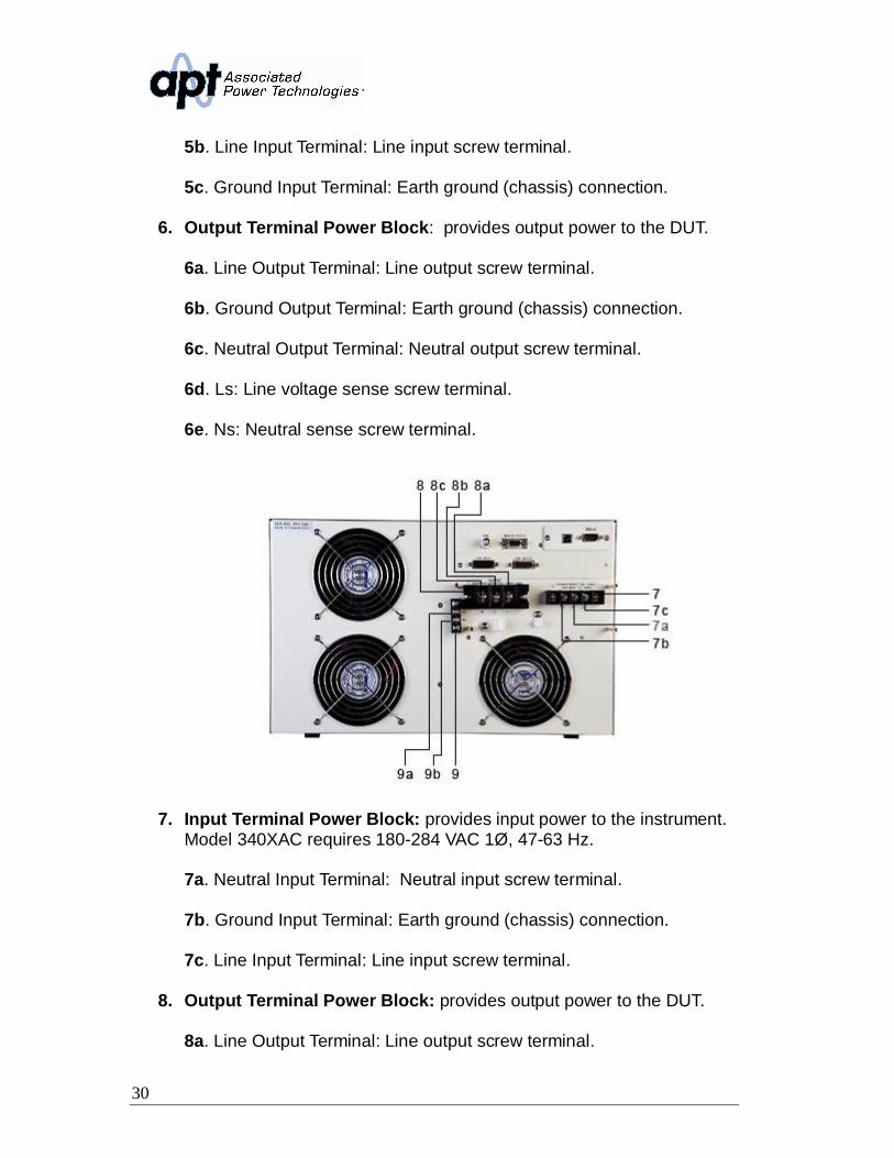
10. Input Terminal Power Block: provides input power to the instrument.Model 360XAC requires 180-264 VAC 1Ø, 180-264 VAC 3Ø or 312-457VAC 3Ø at 47-63 Hz.
11. Output Terminal Power Block: provides output power to the DUT.
11a. Line output Terminal: Line output screw terminal.
12. External Sense Output Terminal Block: provides screw terminals forexternal voltage sense leads.
12a. L: Line voltage sense screw terminal.
32
12b. N: Neutral voltage sense screw terminal.
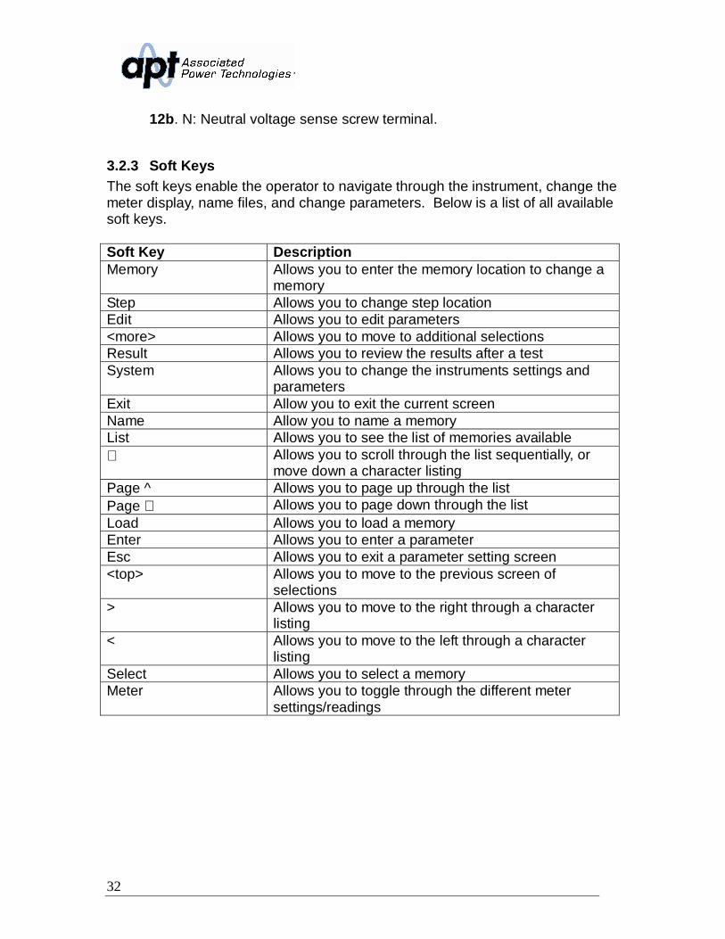
3.2.3 Soft KeysThe soft keys enable the operator to navigate through the instrument, change themeter display, name files, and change parameters. Below is a list of all availablesoft keys.
Soft Key DescriptionMemory Allows you to enter the memory location to change a
memoryStep Allows you to change step locationEdit Allows you to edit parameters<more> Allows you to move to additional selectionsResult Allows you to review the results after a testSystem Allows you to change the instruments settings and
parametersExit Allow you to exit the current screenName Allow you to name a memoryList Allows you to see the list of memories available∨ Allows you to scroll through the list sequentially, or
move down a character listingPage ^ Allows you to page up through the listPage ∨ Allows you to page down through the listLoad Allows you to load a memoryEnter Allows you to enter a parameterEsc Allows you to exit a parameter setting screen<top> Allows you to move to the previous screen of
selections> Allows you to move to the right through a character
listing< Allows you to move to the left through a character
listingSelect Allows you to select a memoryMeter Allows you to toggle through the different meter
settings/readings
33
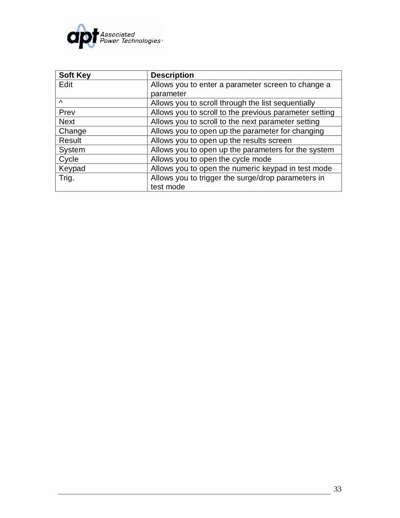
Soft Key DescriptionEdit Allows you to enter a parameter screen to change a
parameter^ Allows you to scroll through the list sequentiallyPrev Allows you to scroll to the previous parameter settingNext Allows you to scroll to the next parameter settingChange Allows you to open up the parameter for changingResult Allows you to open up the results screenSystem Allows you to open up the parameters for the systemCycle Allows you to open the cycle modeKeypad Allows you to open the numeric keypad in test modeTrig. Allows you to trigger the surge/drop parameters in
test mode
34
4. Programming Instructions
4.1 Powering on the InstrumentTurn on the Power switch located on the lower left-hand corner of the front panel.The Initialization screen will appear.
After a few seconds the Initialization screen will change to the Set screen. TheSet screen will be displayed as follows when in PROGRAM Mode:
If you press the <more> soft key within the Set screen, the soft keys will changeto include Result, System, and <top> in the PROGRAM Mode.
If you are in MANUAL Mode there will not be a step number 1 next to the M 1and the Set screen will appear as follows:
35
If you press the <more> soft key within the Set screen, the soft keys will changeto Result, System, and <top> in the MANUAL Mode.
4.1.1 Set Screen DescriptionWhen the instrument is in the Set screen the parameters indicate their currentsettings. However, when the indicator LED is active on the Test/Reset key theparameter settings will display their output value.
Set Screen Parameters Description of ParametersM1-1 Memory and step location1.0s Instrument timer for outputF: 60.0 Hz FrequencyAp: Peak CurrentSet Status of instrument at the present time. Possible
readings are set, dwell, pass, abort, or other failureconditions.
P: 0.0W PowerA: 0.000A CurrentPF: 0.000 Power FactorMemory Memory soft key used to change memory location120.0V (left meter reading) Meter for voltage0.00A (right meter reading) Meter for parameters of F, Ap, P, A & PFQ: 0 VAR Reactive PowerVA: 0 Apparent PowerCF: 0.00 Crest FactorParall-Master Indicates the instrument is set up in Parallel mode
36
as the master (Option 08 only)Parall-Slave Indicates the instrument is set up in Parallel mode
as the slave (Option 08 only)3W: L1-N Indicates the instrument is set up in 1 3W mode
as L1-N (Option 08 only)3W: L2-N Indicates the instrument is set up in 1 3W mode
as L2-N (Option 08 only)4W: A Phase Indicates the instrument is set up in 3 4W mode
as Phase A (Option 08 only)4W: B Phase Indicates the instrument is set up in 3 4W mode
as Phase B (Option 08 only)4W: C Phase Indicates the instrument is set up in 3 4W mode
as Phase C (Option 08 only)
4.1.2 Security
Creating a PasswordCreating a password prevents unauthorized access to the Lock parameters in theSystem menu. Once a password has been created, lock functions will requirethe password to access them.
Press and hold the <top> soft key while powering up the instrument, the EditPassword screen should now be displayed. The display will appear as follows:
You may now type in the new password using the numeric keypad. Press theEnter key to accept the new password or press the Esc key to escape. After youtype in your new password, you will be required to confirm your new password bytyping it again into the “Confirm Password” field. Press the Enter key to confirmthe new password or press the Esc key to escape.
If the password is set to 0, the Lock and Mem Lock parameters may be accessedby editing Lock and Mem Lock soft keys in the System Parameters menu. In thiscase, the key lockout on the front panel is enabled by pressing the Lock button.
If the password has been set to anything but 0, a password entry pop-up screenwill appear to access the Lock and Mem Lock parameters as well as key lockout
37
on the front panel of the unit. The password default is preset to 0 at the factory.
Forgotten PasswordIf you have forgotten your password, a new password should be entered or enter“0” to disable the password. The old password cannot be recovered.
Secure Lock and Mem Lock AccessIf a password has been created, when you press the Lock or Mem Lock soft keyor the key lockout on the front panel, a password pop-up screen will appear. Thepop-up message will appear as follows:
In order for you to access the Lock or Mem Lock parameters, you will now haveto enter the proper password. If you have forgotten the password, please refer tothe Forgotten Password instructions in the Security section.
4.1.3 LockFrom the Set screen press the <more> soft key. Press the System soft key.Highlight the Lock parameter using the ∧, ∨ soft keys. When the Lock parameteris highlighted, you may turn the function ON and OFF by pressing the Changesoft key. Press the Enter key to accept the new setting or the Esc key to canceland return to the original setting. When the Enter key is pressed, the newsecurity setting will take immediate effect.
Selecting Lock “ON” restricts access to parameter and system settings. Thelevel of security is determined by the Mem Lock function.
4.1.4 Mem LockFrom the Set screen press the <more> soft key. Press the System soft key.Highlight the Mem Lock parameter using the ∧, ∨ soft keys. When the MemLock parameter is highlighted, you may turn the function ON and OFF bypressing the Change soft key. Press the Enter key to accept the new setting orthe Esc key to cancel and return to the original setting.
Mem Lock is a sub-function of the Lock setting. In order for the Mem Lock
38
function to work, the Lock must first be turned ON. Selecting the Mem Lock OFFwill allow the user to access all available memory locations but restricts access tomemory and step editing capabilities. Selecting the Mem Lock ON will allow theuser to only run the currently loaded memory.
4.2 System Parameters DescriptionThe system parameters change the overall operation of the AC power source. Ifthe operator elects to edit the system parameters this will apply a universalchange to every memory and step location for the AC power source when in theTest Parameters menu. The operator cannot independently change thesesettings from one memory or step location to another.
1. Auto Run - places the AC power source into one of two modes(PROGRAM/MANUAL). In the PROGRAM Mode the operator will have theability to program individual memories and steps with user selectable testingparameters such as test time, high and low limits, etc.
In the MANUAL Mode the operator will have limited choices in selecting andediting testing parameters. The key difference is that in MANUAL Mode theoperator cannot connect steps or have fixed testing times. The output iseither ON or OFF in the MANUAL Mode.
2. Out Mode - configures the instrument for AC or DC voltage output.
3. Single Step (PROGRAM mode) - controls how the instrument willproceed from one test step to the next in a testing sequence when in the AutoRun mode of PROGRAM.
When this parameter is selected on the source will sequence from one teststep to the next only when the Test/Reset key is pressed between each step.When the Single Step parameter is on the source will pause after each stephas completed a test routine and passed based on the programmed testingparameters. If a PASS occurs for the step the operator can proceed to thenext step in the sequence. If a FAIL occurs for the step the operator will notbe able to proceed in the test sequence. They will have to restart from thebeginning of the test sequence or step number one.
If the parameter is selected off the source will automatically sequence fromone step the next regardless if a pass or failure has occurred for a particularstep.
4. Alarm - controls the volume level of the alarm if a failure is detected. Thissetting is from 1 – 9 with 9 being the loudest volume level.
39
5. Contrast - controls the contrast of the display. The setting is from 1 – 9with 9 being the darkest contrast.
6. Power Up - controls how the output will react once the power switch istoggled on. There are three selections (OFF, ON, LAST). When theparameter is in the OFF state the operator must initialize a test by pressingthe Test/Reset key on power up. If the parameter is in the ON state theoutput will automatically be energized when the source is powered on. If theparameter is in the LAST state the source will provide an output according tohow this setting was last programmed prior to powering off the source.
7. Loop Cycle (PROGRAM Mode) - allows the operator to program thesource to automatically repeat an overall testing sequence when in thePROGRAM Mode. This eliminates the need for the operator to press theTest/Reset key or send multiple test commands to the source to repeat a testsequence. Loop Cycle is only selectable when the source is configured forAC output.
8. V Hi-Lmt (MANUAL Mode) - allows the operator to select a maximumvoltage threshold or ceiling level when programming the output voltage in thetesting parameters screen.
9. V Lo-Lmt (MANUAL Mode) - allows the operator to select a minimumvoltage threshold or floor level when programming the output voltage in thetesting parameters screen.
10.F Hi-Lmt (MANUAL Mode) - allows the operator to select a maximumfrequency threshold or ceiling level when programming the output frequencyin the testing parameters screen. F Hi-Lmt is only selectable when the sourceis configured for AC output.
11.F Lo-Lmt (MANUAL Mode) - allows the operator to select a minimumfrequency threshold or floor level when programming the output frequency inthe testing parameters screen. F Lo-Lmt is only selectable when the sourceis configured for AC output.
12.Start Angle (MANUAL Mode) - provides the operator the flexibility toselect the starting angle of the sine wave when the output voltage isgenerated. Start Angle is only selectable when the source is configured forAC output.
13.End Angle (MANUAL Mode) - provides the operator the flexibility toselect the ending angle of the sine wave when output voltage is terminated.End Angle is only selectable when the source is configured for AC output.
40
14.Results - changes how the data will be displayed on the LCD graphicdisplay after a test is completed. There are three selections available (LAST,ALL, P/F). The LAST setting displays the last step within the programsequence. The ALL setting will display the results of every step within the testsequence in a list format. The P/F, or PASS/FAIL, will display banner text ofPASS or FAIL depending on the results of the test.
15.OC Fold - reduces the voltage, or folds the voltage back, in a linearfashion while maintaining a constant current to help run inductive loads.
16.Transient (MANUAL Mode) - allows the operator to perform transienttesting while in Manual Mode. Transient is only selectable when the source isconfigured for AC output.
17.Lock – allows the operator to lock out the buttons and rotary knob on thefront panel. The level of security is determined by the Mem Lock function.
18.Mem Lock – allows the operator to restrict access to memory and steplocations. Lock must be set to ON in order for Mem Lock to function.
19. Volt Sense - configures the for internal or external voltage sensing. Ifinternal is selected, the instrument will measure the output voltage at theoutput relay. If external is selected, the user must connect sensing wires fromthe Ls and Ns terminals located on rear panel output terminal block to theDUT. Using external sense will provide a more accurate measurement when alarge voltage drop occurs over the output wires.
20.Sync Signal - provides an output signal that may be used to trigger anoscilloscope. The output signal is provided on the rear panel via the BNCconnector labeled Sync. There are 4 Sync signal options: 1) OFF: the Syncoutput is disabled, 2) ON: the Sync signal is active during testing, 3) EVENT:the Sync signal is active when the output voltage changes, 4) FREQ: theSync signal provides a square wave output at the same frequency as theinstrument’s output voltage.
21.Function (Option 08) - configures instruments for either Parallel, 1 3Wor 3 4W operation when multiple AC power sources are interconnected.Parallel operation allows the operator to increase the total output current byconnecting 2 or 3 sources in parallel. 1 3W operation allows the operator toincrease the output voltage to 600 VAC using 2 sources outputting voltage at180 degrees. 3 4W operation allows the operator to configure theinstruments for 3 operation.
41
4.3 Editing System ParametersTo edit System parameters press the <more> soft key from the set screen so thesoft keys read Result, System, and <top>. The screen should be as followswhen in PROGRAM Mode.
When the System soft key is pressed the system parameter screen will open andshow all the parameters available for editing. The screen will look as follows:
If the system parameters are set to MANUAL Mode, the screen will look asfollows:
Use the ∧, ∨ soft keys to navigate through the System parameters. Press theEdit soft key to select the parameter. The parameter will be highlighted black if itis available for editing. Press the Edit soft key to open up the system parameterfor editing. The Exit soft key will return you back to the set screen. If you openany System parameter screen you can navigate through the System parametersby using the Prev and Next soft keys.
42
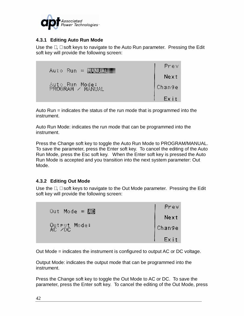
4.3.1 Editing Auto Run ModeUse the ∧, ∨ soft keys to navigate to the Auto Run parameter. Pressing the Editsoft key will provide the following screen:
Auto Run = indicates the status of the run mode that is programmed into theinstrument.
Auto Run Mode: indicates the run mode that can be programmed into theinstrument.
Press the Change soft key to toggle the Auto Run Mode to PROGRAM/MANUAL.To save the parameter, press the Enter soft key. To cancel the editing of the AutoRun Mode, press the Esc soft key. When the Enter soft key is pressed the AutoRun Mode is accepted and you transition into the next system parameter: OutMode.
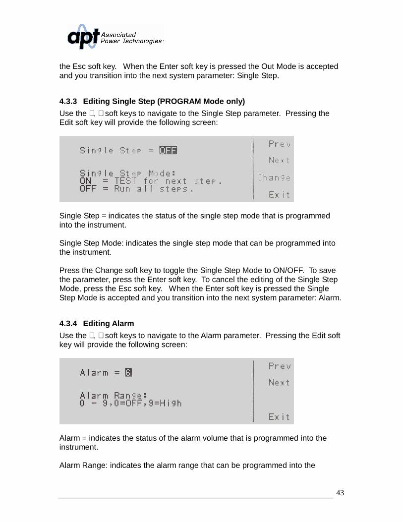
4.3.2 Editing Out ModeUse the ∧, ∨ soft keys to navigate to the Out Mode parameter. Pressing the Editsoft key will provide the following screen:
Out Mode = indicates the instrument is configured to output AC or DC voltage.
Output Mode: indicates the output mode that can be programmed into theinstrument.
Press the Change soft key to toggle the Out Mode to AC or DC. To save theparameter, press the Enter soft key. To cancel the editing of the Out Mode, press
43
the Esc soft key. When the Enter soft key is pressed the Out Mode is acceptedand you transition into the next system parameter: Single Step.
4.3.3 Editing Single Step (PROGRAM Mode only)Use the ∧, ∨ soft keys to navigate to the Single Step parameter. Pressing theEdit soft key will provide the following screen:
Single Step = indicates the status of the single step mode that is programmedinto the instrument.
Single Step Mode: indicates the single step mode that can be programmed intothe instrument.
Press the Change soft key to toggle the Single Step Mode to ON/OFF. To savethe parameter, press the Enter soft key. To cancel the editing of the Single StepMode, press the Esc soft key. When the Enter soft key is pressed the SingleStep Mode is accepted and you transition into the next system parameter: Alarm.
4.3.4 Editing AlarmUse the ∧, ∨ soft keys to navigate to the Alarm parameter. Pressing the Edit softkey will provide the following screen:
Alarm = indicates the status of the alarm volume that is programmed into theinstrument.
Alarm Range: indicates the alarm range that can be programmed into the
44
instrument.
Use the numeric keypad to enter in the alarm volume. Press the Enter soft key toaccept the parameter. To cancel the editing of the alarm volume, press the Escsoft key. To move to the next system parameter for editing, press the Next orPrev soft key. The Exit soft key is also available to return to the Systemparameter screen. When the Enter soft key is pressed the Alarm volume isaccepted and you transition into the next system parameter: Contrast.
4.3.5 Editing ContrastUse the ∧, ∨ soft keys to navigate to the Contrast parameter. Pressing the Editsoft key will provide the following screen:
Contrast = indicates the status of the contrast setting that is programmed into theinstrument.
Contrast Range: indicates the contrast range that can be programmed into theinstrument.
Use the numeric keypad to enter in the contrast. The ranges available are 1 – 9,where 9 is the highest contrast or the darkest. Press the Enter soft key to acceptthe parameter. To cancel the editing of contrast setting, press the Esc soft key.To move to the next system parameter for editing, press the Next or Prev softkey. The Exit soft key is also available to return to the System parameter screen.When the Enter soft key is pressed the Contrast is accepted and you transitioninto the next system parameter: Power Up.
4.3.6 Editing Power UpUse the ∧, ∨ soft keys to navigate to the Power Up parameter. Pressing the Editsoft key will provide the following screen:
45
Power UP = indicates the power up mode that is programmed into theinstrument.
Power UP Mode: indicates the power up mode that can be programmed into theinstrument.
The power up modes available are ON, OFF or LAST. In the ON mode outputwill be supplied on power up of the instrument. In the OFF mode output will NOTbe supplied on power up of the instrument. In the LAST mode output will besupplied according to the last state the instrument was in prior to power off.
Press the Change soft key to toggle the Power UP Mode to ON/OFF/LAST. Tosave the parameter, press the Enter soft key. To cancel the editing of the PowerUp feature press the Esc soft key. When the Enter soft key is pressed thePower Up parameter is accepted and you transition into the next systemparameter.
4.3.7 Editing Loop Cycle (PROGRAM Mode only)Use the ∧, ∨ soft keys to navigate to the Loop Cycle parameter (only selectablefor AC output). Pressing the Edit soft key will provide the following screen:
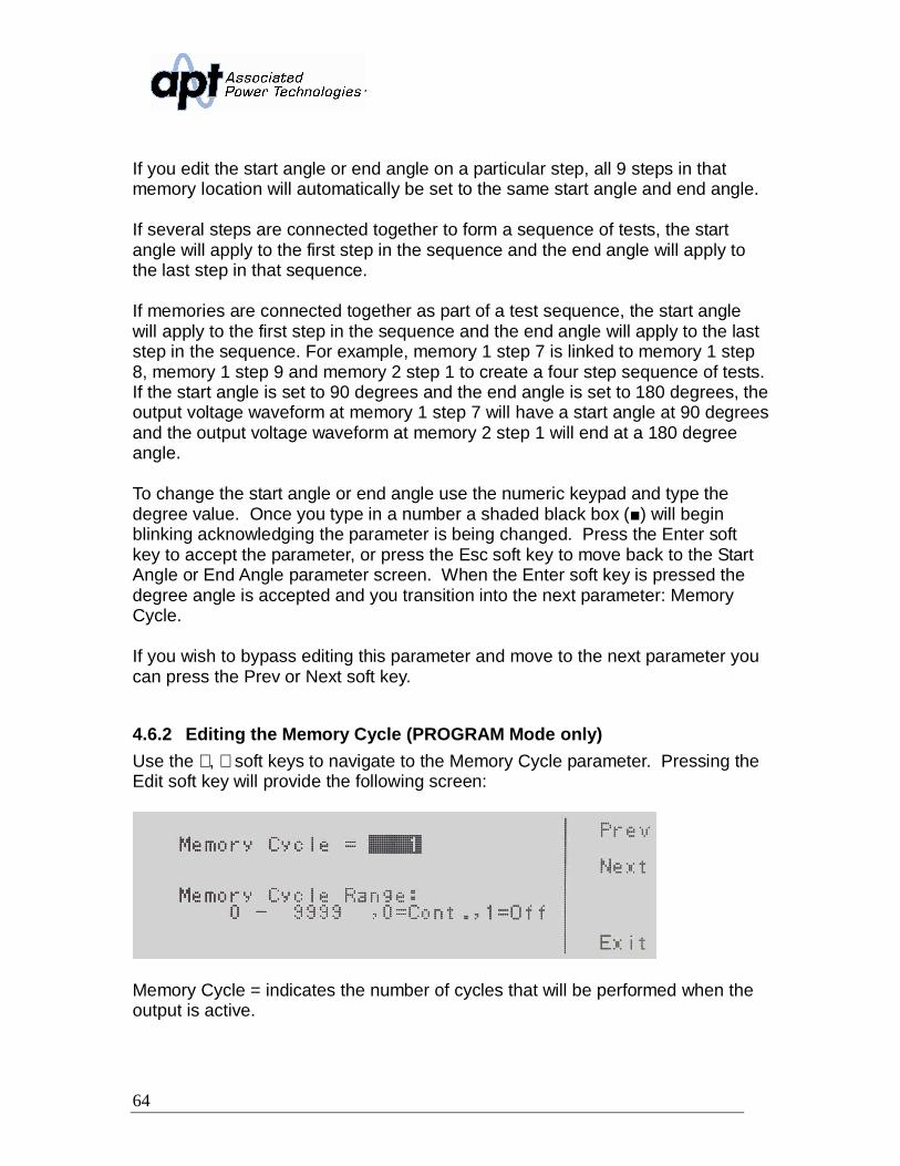
Loop Cycle = indicates the number of loop cycles that will be performed when theoutput is active.
Loop Cycle Range: = indicates the selections available for the Loop CycleRange.
46
The options available are 0 – 9999, 0=Cont., 1=Off. The 0 – 9999 selectionprograms the instrument to repeat the test cycle x number of times. The 0=Cont.selection indicates that the test loop will repeat in . The 1=Off selectionindicates that the test loop will perform only one cycle. Use the numeric keypadto enter in the Loop Cycle Range. Press the Enter soft key to accept theparameter. To cancel the editing of Loop Cycle Range, press the Esc soft key.To move to the next system parameter for editing, press the Next or Prev softkey. The Exit soft key is also available to return to the System parameter screen.When the Enter soft key is pressed the Loop Cycle Mode is accepted and youtransition into the next system parameter.
4.3.8 Editing V Hi-Lmt & V Lo-Lmt (MANUAL Mode only)Use the ∧, ∨ soft keys to navigate to the V Hi-Lmt or V Lo-Lmt parameter.Pressing the Edit soft key will provide one of the following screens:
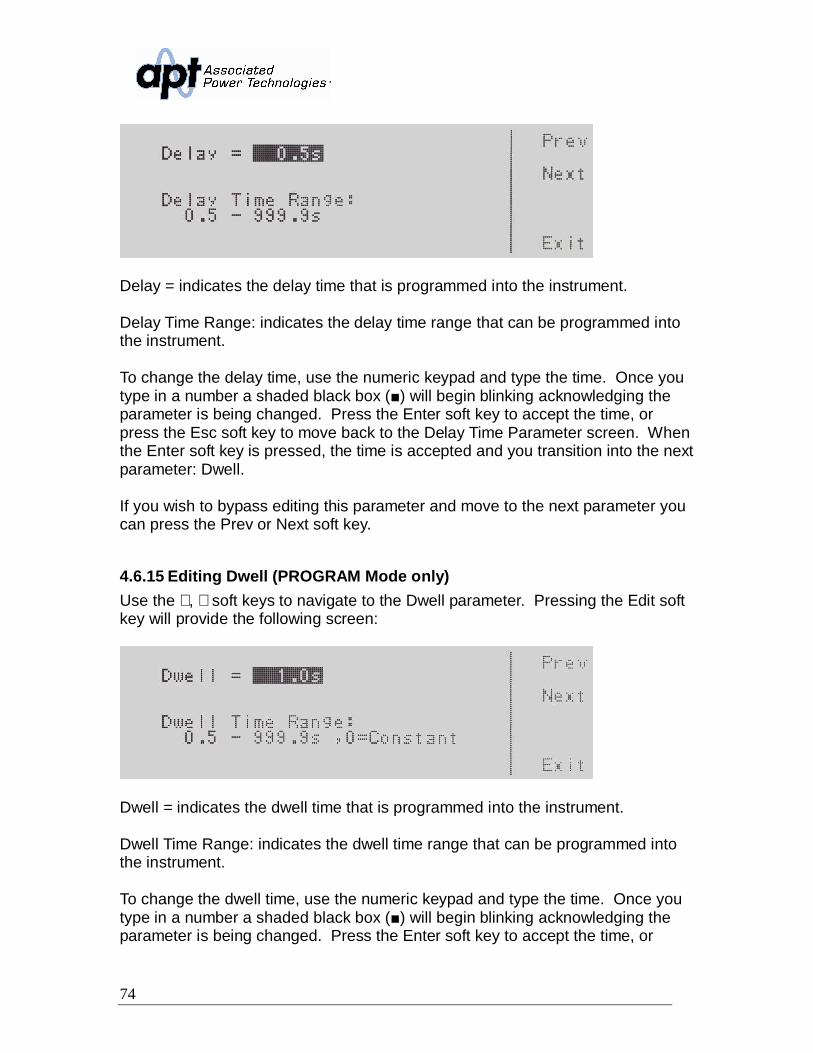
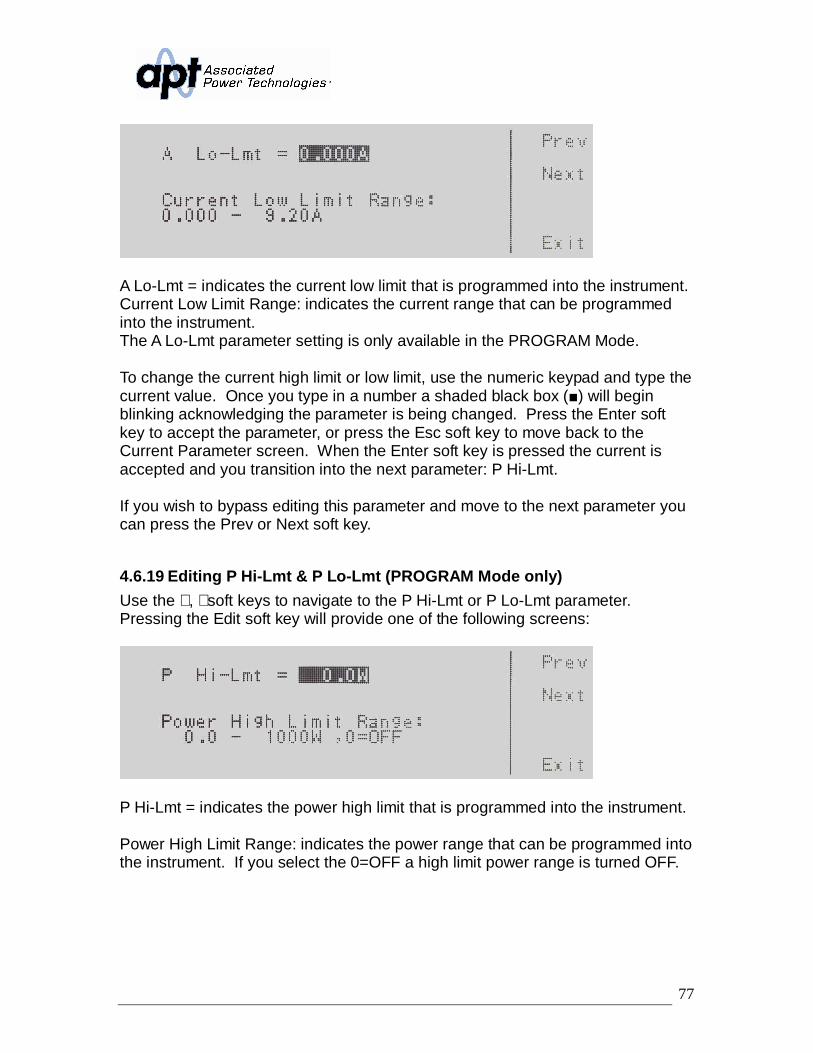
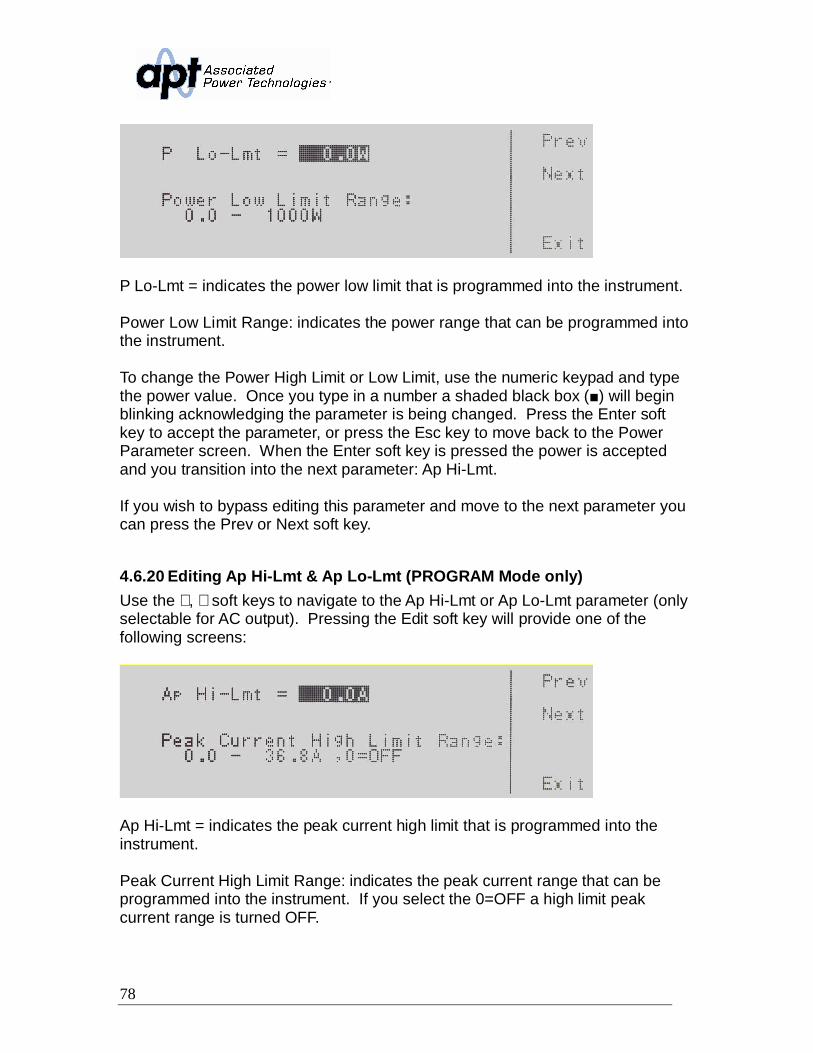
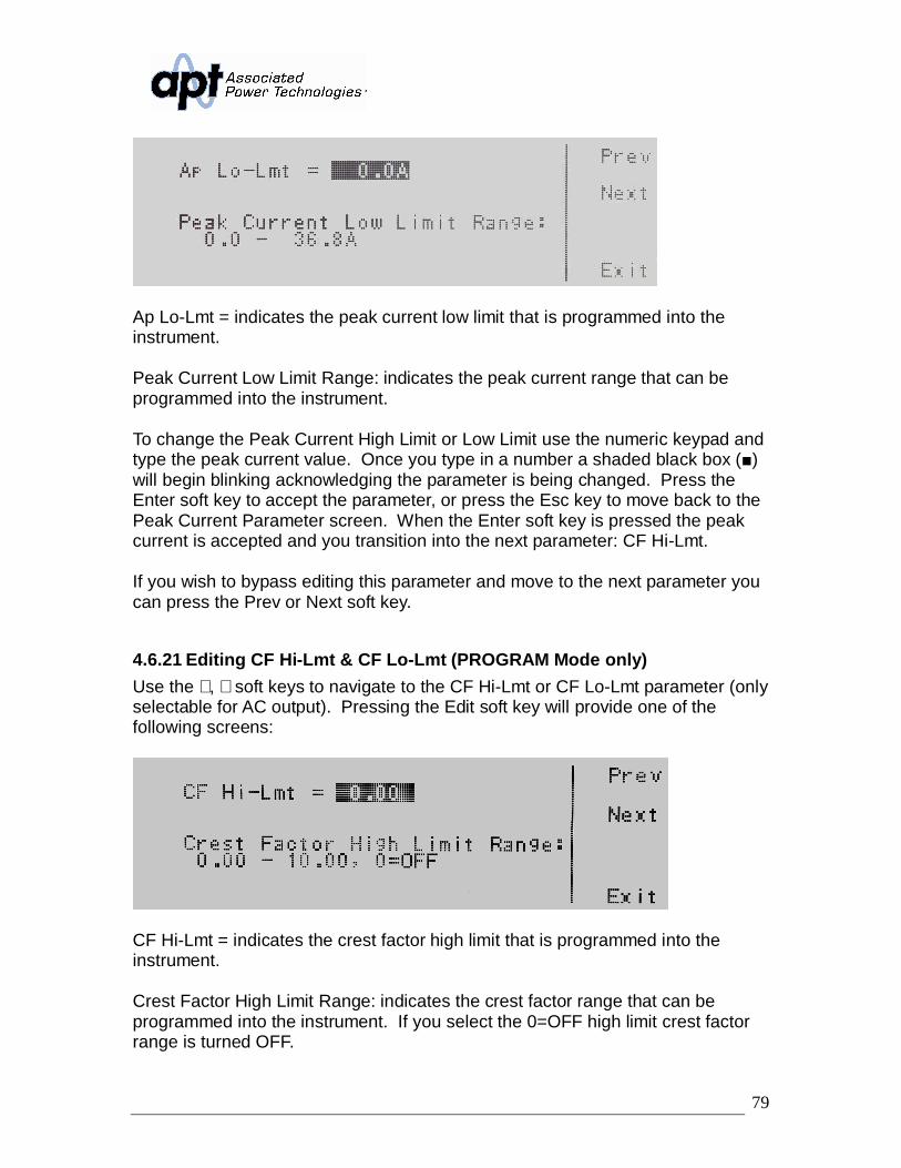
V Hi-Lmt = indicates the voltage high limit that is programmed into theinstrument.
Voltage High Limit Range: indicates the voltage range that can be programmedinto the instrument.
V L-Lmt = indicates the voltage low limit that is programmed into the instrument.
Voltage Low Limit Range: indicates the voltage range that can be programmedinto the instrument.
To change the voltage high limit or low limit use the numeric keypad and type the
47
voltage value. Once you type in a number a shaded black box ( ) will beginblinking acknowledging the parameter is being changed. Press the Enter softkey to accept the parameter, or press the Esc key to move back to the V Hi-Lmtor V Lo-Lmt parameter screen. When the Enter soft key is pressed the voltage isaccepted and you transition into the next system parameter: Frequency Limit.
If you wish to bypass editing this parameter and move to the next parameter youcan press the Prev or Next soft key.
4.3.9 Editing F Hi-Lmt & F Lo-Lmt (MANUAL Mode only)Use the ∧, ∨ soft keys to navigate to the F Hi-Lmt or F Lo-Lmt parameter (onlyselectable for AC output). Pressing the Edit soft key will provide one of thefollowing screens:
F Hi-Lmt = indicates the frequency high limit that is programmed into theinstrument.
Frequency High Limit Range: indicates the frequency range that can beprogrammed into the instrument.
F Lo-Lmt = indicates the frequency low limit that is programmed into theinstrument.
Frequency Lo Limit Range: indicates the frequency range that can beprogrammed into the instrument
To change the frequency high limit or low limit use the numeric keypad and type
48
the frequency value. Once you type in a number a shaded black box ( ) willbegin blinking acknowledging the parameter is being changed. Press the Entersoft key to accept the parameter, or press the Esc key to move back to the F Hi-Lmt or F Lo-Lmt parameter screen. When the Enter soft key is pressed thefrequency is accepted and you transition into the next system parameter: Startand End Angle.
If you wish to bypass editing this parameter and move to the next parameter youcan press the Prev or Next soft key.
4.3.10 Editing Start and End Angle (MANUAL Mode only)Use the ∧, ∨ soft keys to navigate to the Start Angle or End Angle parameter(only selectable for AC output). Pressing the Edit soft key will provide one of thefollowing screens:
Start Angle = indicates the start angle that is programmed into the instrument.
Start Angle Range: indicates the start angle range that can be programmed intothe instrument.
End Angle = indicates the end angle that is programmed into the instrument.
End Angle Range: indicates the end angle range that can be programmed intothe instrument.
To change the start angle or end angle use the numeric keypad and type thedegree value. Once you type in a number a shaded black box ( ) will begin
49
blinking acknowledging the parameter is being changed. Press the Enter soft keyto accept the parameter, or press the Esc key to move back to the Start Angle orEnd Angle parameter screen. When the Enter soft key is pressed the degreeangle is accepted and you transition into the next parameter: Results.
If you wish to bypass editing this parameter and move to the next parameter youcan press the Prev or Next soft key.
4.3.11 Editing ResultsUse the ∧, ∨ soft keys to navigate to the Results parameter. Pressing the Editsoft key will provide the following screen:
Results = indicates the results mode that is programmed into the instrument.
Results Mode: indicates the results mode that can be programmed into theinstrument.
The Results Modes available are ALL, P/F, or LAST. The ALL mode will show allthe testing results after the test is completed. The P/F mode will show only apass/fail banner after the test is completed. The LAST mode will show only thelast test or step that was performed when the test completes. Press the Changesoft key to toggle the results mode to ALL, P/F, LAST. To save the parameter,press the Enter soft key. To cancel the editing of the Results Mode press the Escsoft key. When the Enter soft key is pressed the Results Mode is accepted andyou transition into the next system parameter.
If you wish to bypass editing this parameter and move to the next parameter youcan press the Prev or Next soft key.
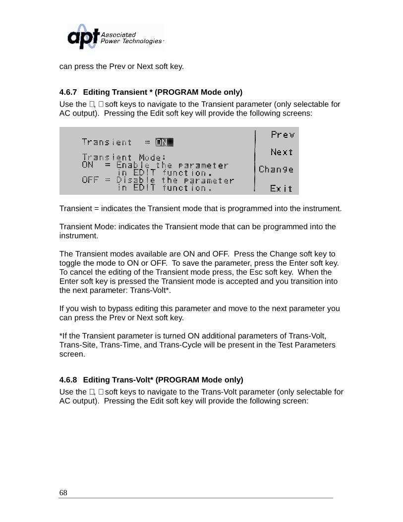
4.3.12 Editing Transient (MANUAL Mode only)Use the ∧, ∨ soft keys to navigate to the Transient parameter (only selectable forAC output). Pressing the Edit soft key will provide the following screens:
50
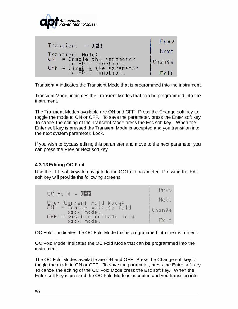
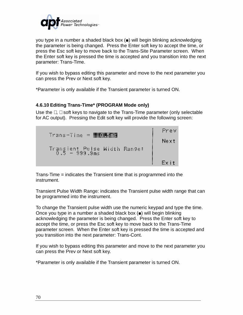
Transient = indicates the Transient Mode that is programmed into the instrument.
Transient Mode: indicates the Transient Modes that can be programmed into theinstrument.
The Transient Modes available are ON and OFF. Press the Change soft key totoggle the mode to ON or OFF. To save the parameter, press the Enter soft key.To cancel the editing of the Transient Mode press the Esc soft key. When theEnter soft key is pressed the Transient Mode is accepted and you transition intothe next system parameter: Lock.
If you wish to bypass editing this parameter and move to the next parameter youcan press the Prev or Next soft key.
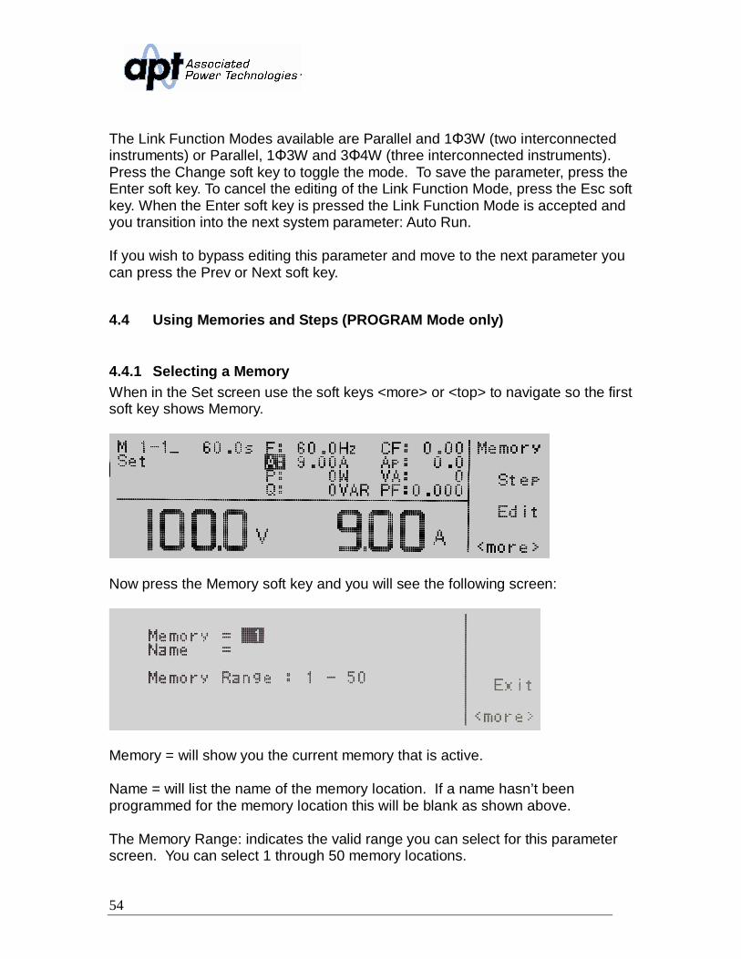
4.3.13 Editing OC FoldUse the ∧, ∨ soft keys to navigate to the OC Fold parameter. Pressing the Editsoft key will provide the following screens:
OC Fold = indicates the OC Fold Mode that is programmed into the instrument.
OC Fold Mode: indicates the OC Fold Mode that can be programmed into theinstrument.
The OC Fold Modes available are ON and OFF. Press the Change soft key totoggle the mode to ON or OFF. To save the parameter, press the Enter soft key.To cancel the editing of the OC Fold Mode press the Esc soft key. When theEnter soft key is pressed the OC Fold Mode is accepted and you transition into
51
the next system parameter: Transient.
If you wish to bypass editing this parameter and move to the next parameter youcan press the Prev or Next soft key.
4.3.14 Editing LockUse the ∧, ∨ soft keys to navigate to the Lock parameter. Pressing the Edit softkey will provide the following screen:
Lock = indicates the security lock that is programmed into the instrument.
Lock Mode: indicates the lock mode that can be programmed into the instrument.
The Lock Modes available are ON and OFF. Press the Change soft key to togglethe mode to ON or OFF. To save the parameter, press the Enter soft key. Tocancel the editing of the Lock Mode, press the Esc soft key. The level of securityis determined by the Mem Lock function. When the Enter soft key is pressed theLock Mode is accepted and you transition into the next system parameter: MemLock.
If you wish to bypass editing this parameter and move to the next parameter youcan press the Prev or Next soft key.
4.3.15 Editing Mem LockUse the ∧, ∨ soft keys to navigate to the Mem Lock parameter. Pressing the Editsoft key will provide the following screen:
52
Mem Lock = indicates the security lock that is programmed into the instrument.
Mem Lock Mode: indicates the lock mode that can be programmed into theinstrument.
The Mem Lock Modes available are ON and OFF. Press the Change soft key totoggle the mode to ON or OFF. To save the parameter, press the Enter soft key.To cancel the editing of the Mem Lock Mode, press the Esc soft key. The MemLock parameter will only initiate if Lock Mode is set ON. When the Enter soft keyis pressed the Mem Lock Mode is accepted and you transition into the nextsystem parameter: Volt Sense.
If you wish to bypass editing this parameter and move to the next parameter youcan press the Prev or Next soft key.
4.3.16 Editing Volt SenseUse the ∧, ∨ soft keys to navigate to the Volt Sense parameter. Pressing the Editsoft key will provide the following screen:
Volt Sense = indicates the voltage sense that is programmed into the instrument.
Voltage Sense Mode: indicates the voltage sense mode that can be programmedinto the instrument.
The Volt Sense Modes available are INT and EXT. Press the Change soft key totoggle the mode to INT or EXT. To save the parameter, press the Enter soft key.To cancel the editing of the Volt Sense Mode, press the Esc soft key. When theEnter soft key is pressed the Volt Sense Mode is accepted and you transition intothe next system parameter: Sync Signal.
If you wish to bypass editing this parameter and move to the next parameter youcan press the Prev or Next soft key.
53
4.3.17 Editing Sync SignalUse the ∧, ∨ soft keys to navigate to the Sync Signal parameter. Pressing theEdit soft key will provide the following screen:
Sync Signal = indicates the Synch signal that is programmed into the instrument.
Sync Signal Mode: indicates the Sync signal mode that can be programmed intothe instrument.
The Synch Signal Modes available are OFF, ON, EVENT, and FREQ. Press theChange soft key to toggle the mode. To save the parameter, press the Enter softkey. To cancel the editing of the Sync Signal Mode, press the Esc soft key. Whenthe Enter soft key is pressed the Sync Signal Mode is accepted and youtransition into the next system parameter: Auto Run.
If you wish to bypass editing this parameter and move to the next parameter youcan press the Prev or Next soft key.
4.3.18 Editing Function (Option 08 only)Use the ∧, ∨ soft keys to navigate to the Function parameter. Pressing the Editsoft key will provide the following screen:
Function = indicates the Link Function mode for operating two instruments in amaster-slave configuration.
Link Function Mode: indicates the Link Function mode that can be programmedinto the instrument.
54
The Link Function Modes available are Parallel and 1 3W (two interconnectedinstruments) or Parallel, 1 3W and 3 4W (three interconnected instruments).Press the Change soft key to toggle the mode. To save the parameter, press theEnter soft key. To cancel the editing of the Link Function Mode, press the Esc softkey. When the Enter soft key is pressed the Link Function Mode is accepted andyou transition into the next system parameter: Auto Run.
If you wish to bypass editing this parameter and move to the next parameter youcan press the Prev or Next soft key.
4.4 Using Memories and Steps (PROGRAM Mode only)
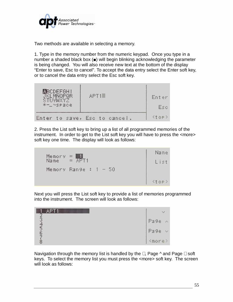
4.4.1 Selecting a MemoryWhen in the Set screen use the soft keys <more> or <top> to navigate so the firstsoft key shows Memory.
Now press the Memory soft key and you will see the following screen:
Memory = will show you the current memory that is active.
Name = will list the name of the memory location. If a name hasn’t beenprogrammed for the memory location this will be blank as shown above.
The Memory Range: indicates the valid range you can select for this parameterscreen. You can select 1 through 50 memory locations.
55
Two methods are available in selecting a memory.
1. Type in the memory number from the numeric keypad. Once you type in anumber a shaded black box ( ) will begin blinking acknowledging the parameteris being changed. You will also receive new text at the bottom of the display“Enter to save, Esc to cancel”. To accept the data entry select the Enter soft key,or to cancel the data entry select the Esc soft key.
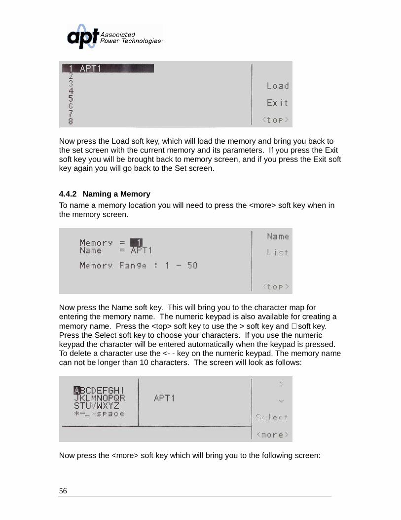
2. Press the List soft key to bring up a list of all programmed memories of theinstrument. In order to get to the List soft key you will have to press the <more>soft key one time. The display will look as follows:
Next you will press the List soft key to provide a list of memories programmedinto the instrument. The screen will look as follows:
Navigation through the memory list is handled by the ∨, Page ^ and Page ∨ softkeys. To select the memory list you must press the <more> soft key. The screenwill look as follows:
56
Now press the Load soft key, which will load the memory and bring you back tothe set screen with the current memory and its parameters. If you press the Exitsoft key you will be brought back to memory screen, and if you press the Exit softkey again you will go back to the Set screen.
4.4.2 Naming a MemoryTo name a memory location you will need to press the <more> soft key when inthe memory screen.
Now press the Name soft key. This will bring you to the character map forentering the memory name. The numeric keypad is also available for creating amemory name. Press the <top> soft key to use the > soft key and ∨ soft key.Press the Select soft key to choose your characters. If you use the numerickeypad the character will be entered automatically when the keypad is pressed.To delete a character use the <- - key on the numeric keypad. The memory namecan not be longer than 10 characters. The screen will look as follows:
Now press the <more> soft key which will bring you to the following screen:
57
To save the memory under the current name you selected via the charactermap/numeric keypad press the Enter soft key.
Pressing the Esc soft key versus the Enter soft key will bring you back to themain memory screen. The screen is as follows:
4.4.3 Selecting a StepTo select a step press the Step soft key and the steps will sequence through.Each time the Step soft key is pressed the step will increase by one increment.There are 9 steps available. After the 9th step you will return to step number 1.
4.5 Test Parameters DescriptionIt is important to note that any changes made within the Test Parameter screenwill be associated with the individual memory and step location indicated on thedisplay. These parameter settings when edited are not universal for eachmemory and step location. The operator must edit each individual memorylocation and step location if multiple test routines are required.
1. Start Angle (PROGRAM Mode only) - provides the operator the flexibilityto select the starting angle of the sine wave when the output voltage isgenerated. Start Angle is only selectable when the source is configured forAC output.
2. End Angle (PROGRAM Mode only) - provides the operator the flexibilityto select the ending angle of the sine wave when output voltage is terminated.End Angle is only selectable when the source is configured for AC output.
58
3. Memory Cycle (PROGRAM Mode only) - gives the operator the flexibilityto program how many times the memory test sequence will repeat when inthe PROGRAM Mode. This eliminates the need for the operator to press theTest/Reset key or send multiple test commands to the source to repeat amemory test sequence.
4. Memory - gives the operator the flexibility to change and edit the memorylocation (1-50).
5. Step (PROGRAM Mode only) - gives the operator the flexibility to changeand edit the step location (1 – 9).
6. Voltage - gives the operator the flexibility to edit the voltage output.
7. Frequency - gives the operator the flexibility to edit the frequency output.Frequency is only selectable when the source is configured for AC output.
8. Transient (PROGRAM Mode only) - gives the operator the flexibility toenable or disable the transient function. Note: Transient Mode simulates theeffect of high speed voltage spikes and sags. For this reason, when TransientMode is set to ON, test parameters 9 through 28 will no longer be displayed.Transient is only selectable when the source is configured for AC output.
9. Ramp Up (PROGRAM Mode only) - gives the operator the flexibility toincrease the voltage output over a duration of time prior to achieving theprogrammed output voltage.
10.Timer Unit (PROGRAM Mode only) - determines the time increment thatwill be used for testing when the source is in PROGRAM Mode. The operatorcan select between Second/Minute/Hour.
11.Delay (PROGRAM Mode only) - gives the operator the flexibility toprogram a time delay, or warm up time. There is a voltage output present fromthe source, but the high and low limit thresholds are essentially ignored duringthis period.
12.Dwell (PROGRAM Mode only) - gives the operator the flexibility toprogram the actual test time. This time begins after the ramp up time hascompleted. The high and low limit thresholds are active once the delay timehas completed.
13.Ramp Down (PROGRAM Mode only) - gives the operator the flexibility toprogram a time duration in which the output voltage is reduced to zero afterthe dwell time has completed.
59
14.Step Cycle (PROGRAM Mode only) - gives the operator the flexibility toprogram the number of looping cycles for a particular step. For example if theoperator would like to have a step repeat five times the step cycle would beprogrammed to five. Step Cycle is only selectable when the source isconfigured for AC output.
15.A Hi-Lmt (PROGRAM Mode) - gives the operator the flexibility to programa maximum current threshold or ceiling level. When this level is reached afailure will occur.
16.A Lo-Lmt (PROGRAM Mode only) - gives the operator the flexibility toprogram a minimum current threshold or floor level. If a minimum currentlevel is not reached a failure will occur. This insures a load is attached to thepower source and there is a minimum current present.
17.P Hi-Lmt (PROGRAM Mode only) - gives the operator the flexibility toprogram a maximum wattage threshold or ceiling level. When this level isreached a failure will occur.
18.P Lo-Lmt (PROGRAM Mode only) - gives the operator the flexibility toprogram a minimum wattage threshold or floor level. If a minimum wattagelevel is not reached a failure will occur. This insures a load is attached to thepower source and there is a minimum wattage present.
19.Ap Hi-Lmt (PROGRAM Mode only) - gives the operator the flexibility toprogram a maximum peak current threshold or ceiling level. When this levelis reached a failure will occur. Ap Hi-Lmt is only selectable when the sourceis configured for AC output.
20.Ap Lo-Lmt (PROGRAM Mode only) - gives the operator the flexibility toprogram a minimum peak current threshold or floor level. If a minimum peakcurrent level is not reached a failure will occur. This ensures a load isattached to the power source and there is a minimum peak current present.Ap Lo-Lmt is only selectable when the source is configured for AC output.
21.CF Hi-Lmt (PROGRAM Mode only) - gives the operator the flexibility toprogram a maximum crest factor threshold or floor level. When this level isreach a failure will occur. CF Hi-Lmt is only selectable when the source isconfigured for AC output.
22.CF Lo-Lmt (PROGRAM Mode only) - gives the operator the flexibility toprogram a minimum crest factor threshold or floor level. If a minimum crestfactor level is not reached a failure will occur. CF Lo-Lmt is only selectablewhen the source is configured for AC output.
60
23.PF Hi-Lmt (PROGRAM Mode only) - gives the operator the flexibility toprogram a maximum power factor threshold or ceiling level. When this levelis reached a failure will occur. PF Hi-Lmt is only selectable is only selectablewhen the source is configured for AC output.
24.PF Lo-Lmt (PROGRAM Mode only) - gives the operator the flexibility toprogram a minimum power factor threshold or floor level. If a minimum powerfactor level is not reached a failure will occur. This insures a load is attachedto the power source and there is a minimum power factor present. PF Lo-Lmtis only selectable when the source is configured for AC output.
25.VA Hi-Lmt (PROGRAM Mode only) - gives the operator the flexibility toprogram a maximum apparent power threshold or floor level. When this levelis reached a failure will occur. VA Hi-Lmt is only selectable when the sourceis configured for AC output.
26.VA Lo-Lmt (PROGRAM Mode only) - gives the operator the flexibility toprogram a minimum apparent power threshold or floor level. If a minimumapparent power level is not reached a failure will occur. VA Lo-Lmt is onlyselectable when the source is configured for AC output.
27.Q Hi-Lmt (PROGRAM Mode only) - gives the operator the flexibility toprogram a maximum reactive power threshold or floor level. When this level isreached a failure will occur. Q Hi-Lmt is only selectable when the source isconfigured for AC output.
28.Q Lo-Lmt (PROGRAM Mode only) - gives the operator the flexibility toprogram a minimum reactive power threshold or floor level. If a minimumreactive power level is not reached a failure will occur. Q Lo-Lmt is onlyselectable when the source is configured for AC output.
29.Trans-Volt - gives the operator the flexibility to program a surge or drop inthe voltage output. Whether the voltage is a surge or a drop depends on thevoltage that is programmed for this parameter. For example if the outputvoltage is programmed at 120 volts and the operator programs in a Trans-Voltof 150 volts this would be a surge of 30 volts. The opposite holds true; if theTrans-Volt is programmed at 90 volts this would be a drop of 30 volts. Trans-Volt is only selectable when the source is configured for AC output.
30.Trans-Site - gives the operator the flexibility to program the specific pointin the sine wave to initialize the surge or the drop voltage. For example sincea 60 Hz sine wave occurs 60 times per second, if the operator programs theTrans-Site for 8 milliseconds the surge or the drop voltage will occur at the
61
halfway point (8 millisecond) of the sine wave or at the 180º point. Trans-Siteis only selectable when the source is configured for AC output.
31.Trans-Time - gives the operator the flexibility to program the overall timeduration of the surge or drop voltage. For example if the Trans-Site is 8milliseconds; the output voltage is 120 volts; the surge voltage is 150 volts;and the Trans-Time is 20 milliseconds when the sine wave reaches the 8millisecond point (180º) the voltage will surge to 150 volts. This surge will holdfor 20 milliseconds before the voltage output returns to 120 volts. Trans-Timeis only selectable when the source is configured for AC output.
32.Trans-Cycle - gives the operator the flexibility to program whether thetransient voltage will occur continuously for each size wave of the test routine.The operator has the choice of selecting 0 or 1-9999. Trans-Cycle is onlyselectable when the source is configured for AC output.
33.Phase Set (Option 08 only) - gives the operator the flexibility to adjustthe hi- and lo-limits for all phases during 1 3W and 3 4W modes. SelectingL1-N will allow the operator to set the limits for the instrument providing L1-Noutput voltage. Selecting L2-N will allow the operator to set the limits for theinstrument providing the L2-N output voltage. Selecting L3-N will allow theoperator to set the limits for the instrument providing the L3-N output voltage.Limits must be set for each phase in all steps (PROGRAM mode only).
34.Prompt (PROGRAM Mode only) - gives the operator the flexibility toprogram a message unique to a particular step. The message will be shownon the LCD graphic display prior to the test beginning for that particular steptest routine. At this point the test routine will be interrupted and the operatormust press the Test/Reset key to begin the test sequence.
24. Connect (PROGRAM Mode only) - gives the operator the flexibility toprogram whether one step will be linked or connected to another step. Forexample in order to links step one to step two, the Connect parameter mustbe turned ON. Steps can only be connected in sequential order.
4.6 Editing Test ParametersTo edit testing parameters press the Edit soft key from the set screen. Thefollowing screen will be displayed if the system parameters are set to PROGRAMMode:
62
Use the ∧, ∨ soft keys to navigate to the testing parameter that will be changed.When you press the Edit soft key you will be moved to the specific parameterscreen for editing. If you press the Exit soft key you will be brought back to theset screen.
If the Transient parameter is turned OFF you will not see the testing parametersfor Trans-Volt, Trans-Site, Trans-Time, and Trans-Cycle. If the Transientparameter is turned ON you will not see the testing parameters for Ramp Up,Timer Unit, Delay, Dwell, Ramp Down, Step Cycle, A Hi-Lmt, A Lo-Lmt, P Hi-Lmt,P Lo-Lmt, Ap Hi-Lmt, Ap Lo-Lmt, CF Hi-Lmt, CF Lo-Lmt, PF Hi-Lmt, PF Lo-Lmt,VA Hi-Lmt, VA Lo-Lmt, Q Hi-Lmt, and Q Lo-Lmt.
If the system parameters are set to MANUAL Mode the following display will beshown:
If the system parameters are set to MANUAL Mode and the Transient parameteris turned ON, the following display will be shown:
63
Use the ∧, ∨ soft keys to navigate to the testing parameter that will be changed.When you press the Edit soft key you will be moved to the specific parameterscreen for editing. If you press the Exit soft key you will be brought back to theset screen.
4.6.1 Editing Start and End Angle (PROGRAM Mode only)Use the ∧, ∨ soft keys to navigate to the Start Angle or End Angle parameter(only selectable for AC output). Pressing the Edit soft key will provide one of thefollowing screens:
Start Angle = indicates the start angle that is programmed into the instrument.
Start Angle Range: indicates the start angle range that can be programmed intothe instrument.
End Angle = indicates the end angle that is programmed into the instrument.
End Angle Range: indicates the end angle range that can be programmed intothe instrument.
64
If you edit the start angle or end angle on a particular step, all 9 steps in thatmemory location will automatically be set to the same start angle and end angle.
If several steps are connected together to form a sequence of tests, the startangle will apply to the first step in the sequence and the end angle will apply tothe last step in that sequence.
If memories are connected together as part of a test sequence, the start anglewill apply to the first step in the sequence and the end angle will apply to the laststep in the sequence. For example, memory 1 step 7 is linked to memory 1 step8, memory 1 step 9 and memory 2 step 1 to create a four step sequence of tests.If the start angle is set to 90 degrees and the end angle is set to 180 degrees, theoutput voltage waveform at memory 1 step 7 will have a start angle at 90 degreesand the output voltage waveform at memory 2 step 1 will end at a 180 degreeangle.
To change the start angle or end angle use the numeric keypad and type thedegree value. Once you type in a number a shaded black box ( ) will beginblinking acknowledging the parameter is being changed. Press the Enter softkey to accept the parameter, or press the Esc soft key to move back to the StartAngle or End Angle parameter screen. When the Enter soft key is pressed thedegree angle is accepted and you transition into the next parameter: MemoryCycle.
If you wish to bypass editing this parameter and move to the next parameter youcan press the Prev or Next soft key.
4.6.2 Editing the Memory Cycle (PROGRAM Mode only)Use the ∧, ∨ soft keys to navigate to the Memory Cycle parameter. Pressing theEdit soft key will provide the following screen:
Memory Cycle = indicates the number of cycles that will be performed when theoutput is active.
65
Memory Cycle Range: = provides the selections available for the Memory Cycle.The options available are 0 – 9999, 0=Cont., 1=Off. The 0 – 9999 selectionprograms the instrument to repeat the test cycle x number of times. The 0=Cont.selection indicates that the test cycle will repeat in . The 1=Off selectionindicates that the test cycle will perform only one cycle.
To change the Memory Cycle, use the number keypad to select the memorycycle range and press the Enter soft key to accept the number. To cancel theediting of the Memory Cycle press, the Esc soft key. When the Enter soft key ispressed and the Memory Cycle is accepted, you transition into the nextparameter: Memory.
If you wish to bypass editing this parameter and move to the next parameter youcan press the Prev or Next soft key.
4.6.3 Editing the Memory (PROGRAM Mode only)Use the ∧, ∨ soft keys to navigate to the Memory parameter. Pressing the Editsoft key will provide the following screen:
Refer to section 4.3.1 for editing the Memory. If you wish to bypass editing thisparameter and move to the next parameter you can press the Prev or Next softkey.
4.6.4 Editing the Step (PROGRAM Mode only)Use the ∧, ∨ soft keys to navigate to the Step parameter. Pressing the Edit softkey will provide the following screen:
66
Step = indicates the step location within the memory.
Step Range: 1 – 9 indicates the step ranges available for selection.
To change the step, use the numeric keypad to select the step number and pressthe Enter soft key to accept the step. To cancel the editing of the step number,press the Esc soft key.
The Step parameter can also be edited from the set screen. If you hit the Stepsoft key, you can use the Step + and Step – soft keys to increase or decrease thestep number.
When the Enter soft key is pressed and the Step is accepted you transition intothe next parameter: Voltage.
If you wish to bypass editing this parameter and move to the next parameter youcan press the Prev or Next soft key.
4.6.5 Editing VoltageUse the ∧, ∨ soft keys to navigate to the Voltage parameter. Pressing the Editsoft key will provide the following screen:
Voltage = indicates the voltage currently programmed into the instrument.
Voltage Range: 0.0- 300 indicates the voltage range that can be programmedinto the instrument.
Voltage Mode: indicates whether the instrument is in the Auto or High mode.
Setting the Voltage mode to Auto, the system will automatically interpret thevoltage range and switch to the high or low voltage output range. Setting theVoltage mode to High will put the output voltage into the high voltage outputrange and the current is limited to half as compared to the current limit in the lowvoltage output range. (Refer to the specification table in 3. Specifications and
67
Controls regarding current output based on voltage output range). Setting ofvoltage range may not influence the existing output voltage setting.
To change the voltage, use the numeric keypad and type the voltage. Once youtype in a number a shaded black box ( ) will begin blinking acknowledging theparameter is being changed. Press the Enter soft key to accept the parameter,or press the Esc soft key to move back to the voltage parameter screen. Whenthe Enter soft key is pressed the voltage parameter is accepted and the systemtransitions into the next parameter: Frequency.
To change the Voltage mode from Auto to High press the Change soft key totoggle between the two selections. To accept the selection, press the Enter softkey. To cancel the selection, press the Esc soft key. You must press the Entersoft key to accept the range. To transition into the next parameter of frequencyoutput you must press the Next soft key if you do not change the voltage setting.
If you wish to bypass editing this parameter and move to the next parameter youcan press the Prev or Next soft key.
4.6.6 Editing FrequencyUse the ∧, ∨ soft keys to navigate to the Frequency parameter (only selectablefor AC output). Pressing the Edit soft key will provide the following screen:
Frequency = indicates the frequency currently programmed into the instrument.Frequency Range: 40.0 – 500 Hz indicates the frequency range that can beprogrammed into the instrument.
To change the frequency, use the numeric keypad and type the frequency. Onceyou type in a number a shaded black box ( ) will begin blinking acknowledgingthe parameter is being changed. Press the Enter soft key to accept theparameter, or press the Esc key to move back to the Frequency Parameterscreen. When the Enter soft key is pressed the frequency is accepted and youtransition into the next parameter: Transient.
If you wish to bypass editing this parameter and move to the next parameter you
68
can press the Prev or Next soft key.
4.6.7 Editing Transient * (PROGRAM Mode only)Use the ∧, ∨ soft keys to navigate to the Transient parameter (only selectable forAC output). Pressing the Edit soft key will provide the following screens:
Transient = indicates the Transient mode that is programmed into the instrument.
Transient Mode: indicates the Transient mode that can be programmed into theinstrument.
The Transient modes available are ON and OFF. Press the Change soft key totoggle the mode to ON or OFF. To save the parameter, press the Enter soft key.To cancel the editing of the Transient mode press, the Esc soft key. When theEnter soft key is pressed the Transient mode is accepted and you transition intothe next parameter: Trans-Volt*.
If you wish to bypass editing this parameter and move to the next parameter youcan press the Prev or Next soft key.
*If the Transient parameter is turned ON additional parameters of Trans-Volt,Trans-Site, Trans-Time, and Trans-Cycle will be present in the Test Parametersscreen.
4.6.8 Editing Trans-Volt* (PROGRAM Mode only)Use the ∧, ∨ soft keys to navigate to the Trans-Volt parameter (only selectable forAC output). Pressing the Edit soft key will provide the following screen:
69
Trans-Volt = indicates the Trans-Volt that is programmed into the instrument.
Transient Voltage Range: indicates the transient voltage range that can beprogrammed into the instrument.
To change the Transient voltage, use the numeric keypad and type the voltage.Once you type in a number a shaded black box ( ) will begin blinkingacknowledging the parameter is being changed. Press the Enter soft key toaccept the voltage, or press the Esc soft key to move back to the Trans-Voltparameter screen. When the Enter soft key is pressed the voltage is acceptedand you transition into the next parameter: Trans-Site.
If you wish to bypass editing this parameter and move to the next parameter youcan press the Prev or Next soft key.
*Parameter is only available if the Trans parameter is turned ON.
4.6.9 Editing Trans-Site* (PROGRAM Mode only)Use the ∧, ∨ soft keys to navigate to the Trans-Site parameter (only selectable forAC output). Pressing the Edit soft key will provide the following screen:
Trans-Site = indicates the transient site that is programmed into the instrument.
Transient Site Range: indicates the transient site range that can be programmedinto the instrument.
To change the Transient site use the numeric keypad and type the time. Once
70
you type in a number a shaded black box ( ) will begin blinking acknowledgingthe parameter is being changed. Press the Enter soft key to accept the time, orpress the Esc soft key to move back to the Trans-Site Parameter screen. Whenthe Enter soft key is pressed the time is accepted and you transition into the nextparameter: Trans-Time.
If you wish to bypass editing this parameter and move to the next parameter youcan press the Prev or Next soft key.
*Parameter is only available if the Transient parameter is turned ON.
4.6.10 Editing Trans-Time* (PROGRAM Mode only)Use the ∧, ∨ soft keys to navigate to the Trans-Time parameter (only selectablefor AC output). Pressing the Edit soft key will provide the following screen:
Trans-Time = indicates the Transient time that is programmed into theinstrument.
Transient Pulse Width Range: indicates the Transient pulse width range that canbe programmed into the instrument.
To change the Transient pulse width use the numeric keypad and type the time.Once you type in a number a shaded black box ( ) will begin blinkingacknowledging the parameter is being changed. Press the Enter soft key toaccept the time, or press the Esc soft key to move back to the Trans-Timeparameter screen. When the Enter soft key is pressed the time is accepted andyou transition into the next parameter: Trans-Cont.
If you wish to bypass editing this parameter and move to the next parameter youcan press the Prev or Next soft key.
*Parameter is only available if the Transient parameter is turned ON.
71
4.6.11 Editing Trans-Cycle* (PROGRAM Mode only)Use the ∧, ∨ soft keys to navigate to the Trans-Cycle parameter (only selectablefor AC output). Pressing the Edit soft key will provide the following screen:
Trans-Cycle = indicates the Transient mode that is programmed into theinstrument.
Transient Trig Mode: indicates the Transient trigger mode that can beprogrammed into the instrument.
If the Transient Trig mode is ON the transient parameters previously programmedwill trigger automatically once the test starts. This will continue to be active untilthe Trig. soft key is pressed or a failure occurs. If the Transient Trig Mode is OFFthe Transient parameter previously programmed will only trigger when the Trig.soft key is pressed
For example, given the following parameters:
Parameter ValueOutput Voltage 100VrmsOutput Frequency 50 HzTransient Voltage 60VrmsTransient Site 25msTransient Time 1ms
72
When the Trig. soft key is hit one time while the Trans-Cycle is set to OFF, thewaveform will look like this:
When the Enter soft key is pressed the time is accepted and you transition intothe next parameter: Prompt
If you wish to bypass editing this parameter and move to the next parameter youcan press the Prev or Next soft key.
*Parameter is only available if the Transient parameter is turned ON.
4.6.12 Editing Ramp Up (PROGRAM Mode only)Use the ∧, ∨ soft keys to navigate to the Ramp Up parameter. Pressing the Editsoft key will provide the following screen:
Ramp Up = indicates the ramp up time that is programmed into the instrument.
Ramp Up Time Range: indicates the ramp up time range that can beprogrammed into the instrument.
73
To change the ramp up time, use the numeric keypad and type the time. Onceyou type in a number a shaded black box ( ) will begin blinking acknowledgingthe parameter is being changed. Press the Enter soft key to accept the time, orpress the Esc key to move back to the Ramp Up Time Parameter screen. Whenthe Enter soft key is pressed the time is accepted and you transition into the nextparameter: Timer Unit.
If you wish to bypass editing this parameter and move to the next parameter youcan press the Prev or Next soft key.
4.6.13 Editing Timer Unit (PROGRAM Mode only)Use the ∧, ∨ soft keys to navigate to the Timer Unit parameter. Pressing the Editsoft key will provide the following screen:
Timer Unit = indicates the timer unit mode that is programmed into theinstrument.
Timer Unit Mode: indicates the timer unit mode that can be programmed into theinstrument.
The power up modes available are Second, Minute or Hour. Press the Changesoft key to toggle the timer unit mode to Second/Minute/Hour. To save theparameter, press the Enter soft key. To cancel the editing of the Timer UnitMode, press the Esc soft key. When the Enter soft key is pressed the Timer UnitMode is accepted and you transition into the next parameter: Delay Time.
4.6.14 Editing Delay (PROGRAM Mode only)Use the ∧, ∨ soft keys to navigate to the Delay parameter. Pressing the Edit softkey will provide the following screen:
74
Delay = indicates the delay time that is programmed into the instrument.
Delay Time Range: indicates the delay time range that can be programmed intothe instrument.
To change the delay time, use the numeric keypad and type the time. Once youtype in a number a shaded black box ( ) will begin blinking acknowledging theparameter is being changed. Press the Enter soft key to accept the time, orpress the Esc soft key to move back to the Delay Time Parameter screen. Whenthe Enter soft key is pressed, the time is accepted and you transition into the nextparameter: Dwell.
If you wish to bypass editing this parameter and move to the next parameter youcan press the Prev or Next soft key.
4.6.15 Editing Dwell (PROGRAM Mode only)Use the ∧, ∨ soft keys to navigate to the Dwell parameter. Pressing the Edit softkey will provide the following screen:
Dwell = indicates the dwell time that is programmed into the instrument.
Dwell Time Range: indicates the dwell time range that can be programmed intothe instrument.
To change the dwell time, use the numeric keypad and type the time. Once youtype in a number a shaded black box ( ) will begin blinking acknowledging theparameter is being changed. Press the Enter soft key to accept the time, or
75
press the Esc soft key to move back to the Dwell Time Parameter screen. Whenthe Enter soft key is pressed, the time is accepted and you transition into the nextparameter: Ramp Down.
If you wish to bypass editing this parameter and move to the next parameter youcan press the Prev or Next soft key.
4.6.16 Editing Ramp Down (PROGRAM Mode only)Use the ∧, ∨ soft keys to navigate to the Ramp Down parameter. Pressing theEdit soft key will provide the following screen:
Ramp Down = indicates the ramp down time that is programmed into theinstrument.
Ramp Down Time Range: indicates the ramp down time range that can beprogrammed into the instrument.
To change the ramp down time, use the numeric keypad and type the time.Once you type in a number a shaded black box ( ) will begin blinkingacknowledging the parameter is being changed. Press the Enter soft key toaccept the time, or press the Esc soft key to move back to the Ramp Down TimeParameter screen. When the Enter soft key is pressed the time is accepted andyou transition into the next parameter: Step Cycle.
If you wish to bypass editing this parameter and move to the next parameter youcan press the Prev or Next soft key.
4.6.17 Editing Step Cycle (PROGRAM Mode only)Use the ∧, ∨ soft keys to navigate to the Step Cycle parameter (only selectablefor AC output). Pressing the Edit soft key will provide the following screen:
76
Step Cycle = indicates the step cycle that is programmed into the instrument.
Step Cycle Range: indicates the step cycle range that can be programmed intothe instrument.
The ranges available are 0 – 9999, 0=Cont., 1=Off. The 0 – 9999 selectionprograms the instrument to repeat the test step cycle x number of times. The0=Cont. selection indicates that the test cycle will repeat in . The 1=Offselection indicates that the test cycle will perform only one cycle. When the“Enter” soft key is pressed the step cycle is accepted and you transition into thenext parameter: A Hi-Lmt.
If you wish to bypass editing this parameter and move to the next parameter youcan press the Prev or Next soft key.
4.6.18 Editing A Hi-Lmt & A Lo-Lmt (PROGRAM Mode only)Use the ∧, ∨ soft keys to navigate to the A Hi-Lmt or Lo-Lmt parameter. Pressingthe Edit soft key will provide one of the following screens:
A Hi-Lmt = indicates the current high limit that is programmed into the instrument.
Current High Limit Range: indicates the current range that can be programmedinto the instrument. If you select the 0=OFF a high limit current range is turnedOFF. The editing of the A Hi-Lmt parameter is available in the PROGRAM andMANUAL Mode.
77
A Lo-Lmt = indicates the current low limit that is programmed into the instrument.Current Low Limit Range: indicates the current range that can be programmedinto the instrument.The A Lo-Lmt parameter setting is only available in the PROGRAM Mode.
To change the current high limit or low limit, use the numeric keypad and type thecurrent value. Once you type in a number a shaded black box ( ) will beginblinking acknowledging the parameter is being changed. Press the Enter softkey to accept the parameter, or press the Esc soft key to move back to theCurrent Parameter screen. When the Enter soft key is pressed the current isaccepted and you transition into the next parameter: P Hi-Lmt.
If you wish to bypass editing this parameter and move to the next parameter youcan press the Prev or Next soft key.
4.6.19 Editing P Hi-Lmt & P Lo-Lmt (PROGRAM Mode only)Use the ∧, ∨soft keys to navigate to the P Hi-Lmt or P Lo-Lmt parameter.Pressing the Edit soft key will provide one of the following screens:
P Hi-Lmt = indicates the power high limit that is programmed into the instrument.
Power High Limit Range: indicates the power range that can be programmed intothe instrument. If you select the 0=OFF a high limit power range is turned OFF.
78
P Lo-Lmt = indicates the power low limit that is programmed into the instrument.
Power Low Limit Range: indicates the power range that can be programmed intothe instrument.
To change the Power High Limit or Low Limit, use the numeric keypad and typethe power value. Once you type in a number a shaded black box ( ) will beginblinking acknowledging the parameter is being changed. Press the Enter softkey to accept the parameter, or press the Esc key to move back to the PowerParameter screen. When the Enter soft key is pressed the power is acceptedand you transition into the next parameter: Ap Hi-Lmt.
If you wish to bypass editing this parameter and move to the next parameter youcan press the Prev or Next soft key.
4.6.20 Editing Ap Hi-Lmt & Ap Lo-Lmt (PROGRAM Mode only)Use the ∧, ∨ soft keys to navigate to the Ap Hi-Lmt or Ap Lo-Lmt parameter (onlyselectable for AC output). Pressing the Edit soft key will provide one of thefollowing screens:
Ap Hi-Lmt = indicates the peak current high limit that is programmed into theinstrument.
Peak Current High Limit Range: indicates the peak current range that can beprogrammed into the instrument. If you select the 0=OFF a high limit peakcurrent range is turned OFF.
79
Ap Lo-Lmt = indicates the peak current low limit that is programmed into theinstrument.
Peak Current Low Limit Range: indicates the peak current range that can beprogrammed into the instrument.
To change the Peak Current High Limit or Low Limit use the numeric keypad andtype the peak current value. Once you type in a number a shaded black box ( )will begin blinking acknowledging the parameter is being changed. Press theEnter soft key to accept the parameter, or press the Esc key to move back to thePeak Current Parameter screen. When the Enter soft key is pressed the peakcurrent is accepted and you transition into the next parameter: CF Hi-Lmt.
If you wish to bypass editing this parameter and move to the next parameter youcan press the Prev or Next soft key.
4.6.21 Editing CF Hi-Lmt & CF Lo-Lmt (PROGRAM Mode only)Use the ∧, ∨ soft keys to navigate to the CF Hi-Lmt or CF Lo-Lmt parameter (onlyselectable for AC output). Pressing the Edit soft key will provide one of thefollowing screens:
CF Hi-Lmt = indicates the crest factor high limit that is programmed into theinstrument.
Crest Factor High Limit Range: indicates the crest factor range that can beprogrammed into the instrument. If you select the 0=OFF high limit crest factorrange is turned OFF.
80
CF Lo-Lmt = indicates the crest factor low limit that is programmed into theinstrument.
Crest Factor Low Limit Range: indicates the crest factor range that can beprogrammed into the instrument.
To change the Crest Factor High Limit or Low Limit use the numeric keypad andtype the peak current value. Once you type in a number a shaded black box ( )will begin blinking acknowledging the parameter is being changed. Press theEnter soft key to accept the parameter, or press the Esc key to move back to theCrest Factor Parameter screen. When the Enter soft key is pressed the crestfactor is accepted and you transition into the next parameter: PF Hi-Lmt.
If you wish to bypass editing this parameter and move to the next parameter youcan press the Prev or Next soft key.
4.6.22 Editing PF Hi-Lmt & PF Lo-Lmt (PROGRAM Mode only)Use the ∧, ∨ soft keys to navigate to the PF Hi-Lmt or PF Lo-Lmt parameter (onlyselectable for AC output). Pressing the Edit soft key will provide one of thefollowing screens:
PF Hi-Lmt = indicates the power factor high limit that is programmed into theinstrument.
Power Factor High Limit Range: indicates the power factor range that can beprogrammed into the instrument. If you select the 0=OFF a high limit power
81
factor range is turned OFF.
PF Lo-Lmt = indicates the power factor low limit that is programmed into theinstrument.
Power Factor Low Limit Range: indicates the power factor range that can beprogrammed into the instrument.
To change the Power Factor High Limit or Low Limit use the numeric keypad andtype the power factor value. Once you type in a number a shaded black box ( )will begin blinking acknowledging the parameter is being changed. Press theEnter soft key to accept the parameter, or press the Esc key to move back to thePower Factor Parameter screen. When the Enter soft key is pressed the powerfactor is accepted and you transition into the next parameter: VA Hi-Lmt.
If you wish to bypass editing this parameter and move to the next parameter youcan press the Prev or Next soft key.
4.6.23 Editing VA Hi-Lmt & VA Lo-Lmt (PROGRAM Mode only)Use the ∧, ∨ soft keys to navigate to the VA Hi-Lmt or VA Lo-Lmt parameter (onlyselectable for AC output). Pressing the Edit soft key will provide one of thefollowing screens:
VA Hi-Lmt = indicates the apparent power high limit that is programmed into theinstrument.
VA High Limit Range: indicates the apparent power range that can be
82
programmed into the instrument. If you select the 0=OFF apparent power rangeis turned OFF.
VA Lo-Lmt = indicates the apparent power low limit that is programmed into theinstrument.
VA Low Limit Range: indicates the apparent power range that can beprogrammed into the instrument.
To change the Apparent Power High Limit or Low Limit use the numeric keypadand type the peak current value. Once you type in a number a shaded black box
) will begin blinking acknowledging the parameter is being changed. Press theEnter soft key to accept the parameter, or press the Esc key to move back to theApparent Power Parameter screen. When the Enter soft key is pressed theapparent power is accepted and you transition into the next parameter: Q Hi-Lmt.
If you wish to bypass editing this parameter and move to the next parameter youcan press the Prev or Next soft key.
4.6.24 Editing Q Hi-Lmt & Q Lo-Lmt (PROGRAM Mode only)Use the ∧, ∨ soft keys to navigate to the Q Hi-Lmt or Q Lo-Lmt parameter (onlyselectable for AC output). Pressing the Edit soft key will provide one of thefollowing screens:
Q Hi-Lmt = indicates the reactive power high limit that is programmed into theinstrument.
83
Reactive Power High Limit Range: indicates the reactive power range that can beprogrammed into the instrument. If you select the 0=OFF reactive power highlimit range is turned OFF.
Q Lo-Lmt = indicates the reactive power low limit that is programmed into theinstrument.
Reactive Power Low Limit Range: indicates the reactive power range that can beprogrammed into the instrument.
To change the Reactive Power High Limit or Low Limit use the numeric keypadand type the peak current value. Once you type in a number a shaded black box
) will begin blinking acknowledging the parameter is being changed. Press theEnter soft key to accept the parameter, or press the Esc key to move back to theReactive Power Parameter screen. When the Enter soft key is pressed the peakcurrent is accepted and you transition into the next parameter: Prompt.
If you wish to bypass editing this parameter and move to the next parameter youcan press the Prev or Next soft key.
4.6.25 Editing PromptUse the ∧, ∨ soft keys to navigate to the Prompt parameter. Pressing the Editsoft key will provide the following screen:
Press the “Edit” soft key and a blinking shaded black box ( ) will appear notifyingyou that characters can be inserted into the prompt field. Use the soft keys > and∨ to highlight the character you would like to use. Press the Select soft key to
84
accept the character. You can also use the numeric keypad to enter characters.When the numeric keypad is used the number is inserted automatically and theSelect soft key is not needed. To delete a character use the Backspace key <- -located on the numeric keypad. There are 32 characters spaces available for theprompt message. To save the prompt message press the <more> soft key whichwill bring you to the following screen.
Press the Enter soft key to accept the prompt message. To cancel the promptmessage, press the Esc soft key. When the Enter soft key is pressed the promptis accepted and you transition into the next parameter: Step Cycle.
If you wish to bypass editing this parameter and move to the next parameter youcan press the Prev or Next soft key.
4.6.26 Editing ConnectUse the ∧, ∨ soft keys to navigate to the Connect parameter. Pressing the Editsoft key will provide the following screen:
Connect = indicates the status of the connect mode that is programmed into theinstrument.
Step Connect Mode: indicates the connect mode that can be programmed intothe instrument.
Press the Change soft key to toggle the connect mode ON/OFF. To save theparameter, press the Enter soft key. To cancel the editing of the step mode pressthe Esc soft key. When the Enter soft key is pressed the connect mode is
85
accepted and you transition into the next parameter: Memory Cycle.
If you wish to bypass editing this parameter and move to the next parameter youcan press the Prev or Next soft key.
When the connect mode is ON there will be an underscore _ next to the stepnumber in the set screen. It will look as follows:
4.6.27 Editing Phase Set (Option 08 – PROGRAM Mode only)Use the ∧, ∨ soft keys to navigate to the Phase Set parameter. Pressing the Editsoft key will provide the following screen:
Phase Set = indicates the Phase Setting mode for operating two instruments in amaster-slave configuration.
Phase Setting Mode: indicates the Phase Setting mode that can be programmedinto the instrument.
The Phase Setting Modes available are L1-N and L2-N (two interconnectedinstruments) or L1-N, L2-N and L3-N (three interconnected instruments). Pressthe Change soft key to toggle the mode. To save the parameter, press the Entersoft key. To cancel the editing of the Phase Setting Mode, press the Esc soft key.When the Enter soft key is pressed the Phase Setting Mode is accepted and youtransition into the next system parameter: Function.
If you wish to bypass editing this parameter and move to the next parameter youcan press the Prev or Next soft key.
86
4.7 Reviewing Test ResultsTo review the testing results press the Result soft key in the set screen. You mayhave to use the <more> soft key to get to the Results soft key. The screen willlook as follows when you are in the correct screen:
Press the Result soft key to view the results. The screen will look as follows:
If you have multiple steps linked together you will have to use the navigation softkeys in order to toggle through each step to review the results. Press the Exitsoft key to move back to the set screen.
87
5. Test Modes
5.1 Description of Test ModesWithin the System Parameter settings of Auto Mode you have two selectionsavailable (PROGRAM/MANUAL).
The PROGRAM Mode will run your testing routine according to the parametersthat have been entered within the testing parameters screen when theTEST/RESET key is pressed. In most cases there will be a testing timeassociated with the test mode unless the time has been selected to or thecycle mode is ON.
The MANUAL Mode will run your testing routine according to the parameterscurrently programmed into the instrument when the Test/Reset key is pressed.However, there is no test time associated with the MANUAL Mode. The output iscontinuous until the Test/Reset key is pressed again.
5.2 Initializing a Test in PROGRAM Mode
5.2.1 AC OutputWhen the AUTO RUN parameter in the System Parameters menu is set toPROGRAM Mode the Set screen will be displayed as follows:
To initialize the test press the Test/Reset key and the LED for the key willilluminate. The text “Set” on the set screen will turn to Dwell, in addition your softkeys will change to include Meter, Cycle, Keypad, and Trig*.
*Only available if Transient parameter is set to OFF.
88
If you press the Meter soft key a shaded black box ( ) will highlight the meterparameters of F:, A:, P:, Q:, CF:, Ap, VA:, PF:, and the display will read the outputon the on the right side of the display. Every time the meter key is pressed it willtoggle through the meter parameters.
If you press the Cycle soft key the display will change and provide you the cycleinformation from Step, Memory, and Loop. This will take the place of the meterreading on the right side of the display. To move back to the meter reading,press the Meter soft key.
If you press the Keypad soft key the display will show the text Voltage = abovethe voltage meter on the left hand side of the display. A shaded black box ( ) willbe flashing waiting for a voltage value to be entered from the numeric keypad.Once the value has been typed into the instrument you must press the Enter softkey to accept the value. The Esc soft key is available to exit out of this mode andmove back to the test screen.
If you press the Trig. soft key you will hear a beep which is notification that thetrigger has been activated for the Transient parameters that have been enteredinto the instrument.
When the test cycle has completed the display will show you the meter readingsand the soft keys will change to Meter, Cycle, Exit. You can toggle through themeter displays or show the cycles by pressing the appropriate soft keys. Thedisplay will also show you the test status where the text “Dwell” was located. Ifthe test passes you will see Pass. If you press the Exit soft key the screen willreset back to the set screen.
89
5.2.2 DC OutputWhen the AUTO RUN parameter in the System Parameters menu is set toPROGRAM Mode the Set screen will be displayed as follows:
To initialize the test press the Test/Reset key and the LED for the key willilluminate. The text “Set” on the set screen will turn to Dwell, in addition your softkeys will change to include Meter and Keypad. The output will run continuouslyuntil the Test/Reset key is pressed again, or there is a failure condition.
When the RESET key is pressed or a Hi-Limit failure occurs, the instrument DCoutput voltage has a fixed 1 second ramp down discharge time. The Test/ResetLED flashes during this ramp down period to indicate the output is still active.
If you press the Meter soft key a shaded black box ( ) will highlight the meterparameters P: or A: and the display will read the output on the right side of thedisplay. Every time the meter key is pressed it will toggle between the two meterparameters.
If you press the Keypad soft key the display will show the text Voltage = abovethe voltage meter on the left hand side of the display. A shaded black box ( ) willbe flashing waiting for a voltage value to be entered from the numeric keypad.Once the value has been typed into the instrument you must press the Enter softkey to accept the value. The Esc soft key is available to exit out of this mode andmove back to the test screen.
90
5.3 Initializing a Test in MANUAL Mode
5.3.1 AC OutputWhen the AUTO RUN parameter in the System Parameters is set to theMANUAL Mode the Set screen will be displayed as follows:
To initialize the test press the Test/Reset key and the LED for the key willilluminate. The text “Set” on the set screen will turn to Dwell, in addition your softkeys will change to include Meter, AUTO, Keypad, and Trig. In the MANUALMode output will run continuously until the Test/Reset key is pressed again, orthere is a failure condition.
If you press the Meter soft key a shaded black box ( ) will highlight the meterparameters of F:, A:, P:, Q:, CF:, Ap:, VA:, PF:, and the display will read theoutput on the on the right side of the display. Every time the meter key ispressed it will toggle through the meter parameters.
If you press the AUTO soft key a shaded black box ( ) will toggle between AUTO& HIGH. The AUTO Mode will toggle the voltage range from low to high basedon the voltage setting. This allows you to receive maximum current based on thevoltage range you have selected. If the HIGH Mode is selected the current willalways be at 50% of the maximum capacity of the instrument at any voltage levelselected whether it would be in the low or high range.
If you press the Keypad soft key the display will show the text Voltage = abovethe voltage meter on the left hand of the display. A shaded black box ( ) will be
91
flashing waiting for a voltage value to be entered from the numeric keypad. Oncethe value has been typed into the instrument you must press the Enter soft key toaccept the value. The Esc soft key is available to exit out of this mode and moveback to the test screen.
In the MANUAL Mode the Rotary Knob on the front panel also becomes active. Itcan be used to adjust voltage or frequency. When the instrument is in an idlestate, it can also be used to edit the Hi-Lmt. To adjust the frequency with theRotary Knob the meter selection must be on F. To adjust the voltage with theRotary Knob the meter can be on any selection except F. To adjust the Hi-Lmtwith the Rotary Knob the meter selection must be on Hi-Lmt. To adjust the output,rotate the knob either clockwise or counterclockwise. Clockwise rotations willincrease the output, whereas counterclockwise rotations will decrease the output.If LOCK is set to ON, the Rotary Knob is disabled.
If you press the Trig. soft key you will hear a beep which is notification that thetrigger has been activated for the Transient parameters that have been enteredinto the instrument.
5.3.2 DC OutputWhen the AUTO RUN parameter in the System Parameters menu is set toMANUAL Mode the Set screen will be displayed as follows:
To initialize the test press the Test/Reset key and the LED for the key willilluminate. The text “Set” on the set screen will turn to Dwell, in addition your softkeys will change to include Meter and Keypad. The output will run continuouslyuntil the Test/Reset key is pressed again, or there is a failure condition.
When the RESET key is pressed or a Hi-Limit failure occurs, the instrument DCoutput voltage has a fixed 1 second ramp down discharge time. The Test/ResetLED flashes during this ramp down period to indicate the output is still active.
If you press the Meter soft key a shaded black box ( ) will highlight the meterparameters P: or A: and the display will read the output on the right side of thedisplay. Every time the meter key is pressed it will toggle between the two meter
92
parameters.
If you press the Keypad soft key the display will show the text Voltage = abovethe voltage meter on the left hand side of the display. A shaded black box ( ) willbe flashing waiting for a voltage value to be entered from the numeric keypad.Once the value has been typed into the instrument you must press the Enter softkey to accept the value. The Esc soft key is available to exit out of this mode andmove back to the test screen.
The Rotary Knob on the front panel also becomes active. To adjust the voltagerotate the knob either clockwise or counterclockwise. Clockwise rotations willincrease the voltage, whereas counterclockwise rotations will decrease thevoltage. If LOCK is set to ON, the Rotary Knob is disabled.
93
6. Multiple Instrument Operation
6.1 Configuring Sources for Parallel and Polyphase OperationThe 300XAC is a modular power source capable of interconnection to up to two(2) additional sources with Option 08 Linking Card installed. While all 300XACmodels are modular, each model is only capable of being interconnected withanother instrument of the same model. For example, model 310XAC may onlybe interconnected with either one (1) or two (2) additional model 310XACinstruments. A model 310XAC cannot be interconnected with a different modelsuch as the 320XAC.
6.1.1 Operating Mode DefinitionsWhen multiple instruments are connected together, the operator has the option torun the instruments in Parallel or Polyphase modes.
Parallel mode - two (2) or three (3) instruments connected together in parallelmay be used to increase the total current output of the system.
Polyphase mode - two (2) or three (3) instruments connected together may beused in Polyphase mode. There are two versions of Polyphase mode. If two (2)instruments are interconnected 1 3W mode is available. This mode allows theoperator to increase the output voltage to up to 600 VAC by configuring the twosources to output voltage at 180 degrees apart. If three (3) instruments areinterconnected 3 4W mode is available. This mode allows the operator toconfigure the instruments for three phase operation. Each phase will outputvoltage 120 degrees apart.
6.1.2 Connecting the Interface CableIn order to setup instruments to function in Parallel or Polyphase mode, Option08 Linking Card is needed for each instrument that will be interconnected. TheOption 08 Linking Card will be supplied with an interface cable that must beconnected between each linked instrument. Connect the female end of theinterface cable to the connector labeled “Interface Out” on the Option 08 LinkingCard on the rear panel of the instrument that will be set up as the Master.Connect the male end of the interface cable to the connector labeled “InterfaceIn” on the Option 08 Linking Card on the rear panel of the instrument that will beset up as Slave (1). If another slave unit needs to be added, connect the femaleend of the additional interface cable to the connector labeled “Interface Out” onthe rear panel of the Slave (1) instrument. Connect the male end of the interfacecable to the connector labeled “Interface In” on the Option 08 Linking Card on therear panel of the instrument that will be set up as Slave (2).
94
Note: APT’s SmartDetect feature will automatically configure the instruments asmaster and slave depending on how the interface cable is connected. Theoperator does not need to adjust any settings on the instruments’ front panel.APT’s SmartConfig feature will automatically adjust the firmware to display theappropriate output modes depending on the number of sources that areinterconnected.
6.1.3 Output Wiring DiagramsThe following diagrams detail the correct setup for configuring multiple 300XACpower sources to operate in Parallel and Polyphase modes. Make sure that theinstruments are OFF before attempting to make any connections.
Parallel Mode (1 2W)In this condition, each instruments’ Line output must be connected together andeach instruments’ Neutral output must be connected together at the load. Seethe figure below for the Parallel mode output wiring diagram:
Polyphase Mode (1 3W)In this configuration, the operator must connect the Neutrals of both instrumentstogether and utilize both Line outputs to achieve full voltage. See the figure
95
below for the 1 3W output wiring diagram:
Polyphase Mode (3 4W)In this configuration, the operator must connect the Neutrals of all sourcestogether and utilize the Line outputs to achieve full voltage. See the figure belowfor the 3 4W output wiring diagram:
96
6.2 Power Up Considerations in Parallel and Polyphase ModeAfter making the appropriate output connections and verifying the interfacecable(s) are connected correctly, turn on the power to all instruments. Theinitialization screen will be displayed:
If a slave instrument fails to power on the alarm will sound and the following errormessage will be displayed:
97
If multiple slave units are connected, the master will prompt the operator toenable the second slave. The prompt will be displayed as follows:
Press the Yes soft key to enable the second slave instrument. Press the No softkey to disable the second slave instrument.
After the Yes or No soft key has been pressed, the set screen will be displayed.The set screen will change depending on the type of mode for which theinstruments are configured. If the instruments are set for Parallel mode the Setscreen will appear as follows:
If two (2) instruments are connected and set for Polyphase mode the Set screenwill appear as follows:
98
If three (3) instruments are connected and set for Polyphase mode the Setscreen will appear as follows:
6.3 Initializing a Test in Parallel or Polyphase ModeThe front panel display(s) of the slave unit(s) will not be editable in Parallel orPolyphase modes. All user editable controls will be available from the front panelof the master instrument. After all parameters have been entered into theinstrument, the operator may begin the test.
While a test is running, the front panel display will include the Phase key.Pressing the Phase key allows the operator to view the meters for each individualphase, as well as total measurements.
For detailed information on initializing a test, please refer to section 5. TestModes.
6.4 Error Messages in Parallel and Polyphase ModeIf the power to the master instrument is turned off during operation or theinterface cable is unplugged, the slave instrument display will show the followingmessage:
99
If the power to a slave instrument is turned off during operation or the interfacecable is unplugged, the master instrument display will show the followingmessage:
100
7. Displayed MessagesDuring any abnormal conditions, there are several error messages that could beindicated in the display. When an abnormal condition occurs the output willdisable and the alarm will sound. The Test/Reset LED indicator will also beginflashing. Pressing the Test/Reset key will reset the audible alarm and theabnormal condition will be displayed.
All error messages occur in abnormal conditions andtherefore must be recorded. Check the cause of the error to ensure the problemis eliminated before restarting the operation, or contact Associated PowerTechnologies, Inc., or our official distributors for further assistance.
Display Message DefinitionOTP Over Temperature ProtectionOCP Over Current ProtectionOPP Over Power ProtectionOVP Output Voltage ProtectionA-SH Amplifier Shutdown Protection
7.1 OTP – Over Temperature ProtectionDisplayed if the heat sink of the instrument has exceeded 130º C. The voltageand current displays will show the overloaded voltage or current respectively.The LED indicator for the Test/Reset key will be blinking.
7.2 OCP – Over Current ProtectionDisplayed if the output current has exceeded 110% of maximum current rating for1 second or there is a short circuit for 6 seconds. The LED indicator for theTest/Reset key will be blinking.
7.3 OPP – Over Power ProtectionDisplayed if the output power has exceeded 110% of maximum power rating for 1second. The LED indicator for the Test/Reset key will be blinking.
7.4 OUP – Output Voltage ProtectionDisplayed if the output voltage has exceeded 5 V of the setting voltage in the0-150V range, or has exceeded 10 V of the setting voltage in the 0-300V range.The LED indicator for the Test/Reset key will be blinking.
WARNING
101
If an OVP error occurs on the next power up cycle on the displays will showVolt Err.
7.5 A-SH – Amplifier Shutdown ProtectionDisplayed if the amplifier is in an abnormal condition. The LED indicator for theTest/Reset key will be blinking.
102
8. Remote PLC
8.1 Signal OutputThe rear panel connector of the 300XAC Series provides output signals toremotely monitor PASS, FAIL, and PROCESSING conditions via a 9-Pin D-typeconnector. When a terminal becomes active the relay closes thereby allowingthe external voltage to operate an external device. The following table providesthe conditions of each pin and the relay state.
Condition Pins Relay StatePASS Connection between PIN
1 & PIN 2Closes on PASS andis opened on next testinitialized
FAIL Connection between PIN3 & PIN 4
Closes on FAIL and isopened when nexttest is initialized
PROCESSING Connection between PIN5 & PIN 6
Closes when testinitialized and opensafter test is completed
8.2 Signal Input - 7 Memory Recall (Opt. 04)The 300XAC Series also provides an optional remote input interface (Opt. 04) tocontrol any test operation via remote. The 9-Pin D-Type connector signals forTest, Reset, and 7 Memories (M1 – M7) input control signals. PLC remotefunctions will be activated once the PLC Remote from the System setupParameter is turned on. Upon turning on the PLC Remote setting, theTEST/RESET LED will be lit and the buzzer will beep twice before returning tothe RESET condition, when any key on the front panel is pressed. Wheneverthere is an abnormal output detected the instrument can be reset by pressing theTEST/RESET key or the initializing a reset through the PLC remote
103
The following table provides the conditions of each pin and the relay state:
Condition Pins Relay StateTEST Connection between PIN 3 & PIN
5Momentary contactclosure
RESET Connection between PIN 2 & PIN5
Momentary contactclosure
Memory Input ControlSelection of up to 7 memory locations is achieved by using a Normally Open(N.O) Momentary Button. The truth table below provides the pin locationsneeded in order to select the memories.
Memory PIN 1 PIN 9 PIN 8M1 OFF OFF ONM2 OFF ON OFFM3 OFF ON ONM4 ON OFF OFFM5 ON OFF ONM6 ON ON OFFM7 ON ON ON
104
9. Bus Remote Interface GPIB/RS-232This section provides information on the proper use and configuration of busremote interface. The RS-232 remote interface is standard on model 300XACseries but the GPIB (IEEE-488) interface option can be substituted for the RS-232 interface. Please refer to the Option section of this manual for details on the300XAC series options. The RS-232 interface also uses the same command setas the GPIB interface for setting of test parameters. However there are manyfunctions of the GPIB 488.2 interface that are not available through RS-232. TheIEEE-488 interface included with the 300XAC series conforms to therequirements of the IEEE-488.2 standard.
9.1 RS-232 InterfaceThis interface is standard on the 300XAC series. This interface provides all ofthe control commands and parameter setting commands of the GPIB interfacewith the exception of the 488.2 Common Command the Status Reportingcommands and SRQ capability. All commands can be found in the commandlist, section 12.9 of this manual. The identification command *IDN is alsoavailable through RS-232.
9.1.1 RS-232 ConnectorThe RS-232 connection is configured as follows for a 9 pin Serial Port Interface.
RD 2 2 RD
TD 3 3 TD
SIG 5 5 SIGGND GND
9.1.2 Communication Port ConfigurationThe COM port should have the following configuration:
• 9600 baud• 8 data bits• No polarity• 1 stop bit
This interface does not support XON/XOFF protocol and any hardwarehandshaking. The controller should be configured to ignore the HandshakingLines DTR (PIN 4,), DSR (PIN 6) and RTS (PIN 9). If the port cannot be
105
configured through software to ignore the lines, the handshaking lines shouldthen be jumped together in two different sets. The PIN 4 and 6 jumped togetherwhile PIN 7 & 8 jumped together at the controller end of the cable.
9.1.3 Sending and Receiving Commands
Sending CommandsWhen sending commands over the RS-232 bus the instrument will send aresponse string of 06 Hex or 6 decimal and Acknowledge (ACK) ASCII controlcode if the transfer was recognized and completed by the instrument. If there isan error with the command string that is sent, the instrument will respond with 15Hex or 21 decimal and the Not Acknowledge (NAK) ASCII code. The ACK orNAK response allows for software handshaking in order to monitor and controldata flow.
Receiving CommandsWhen requesting data from the instrument it will automatically send the data backto the controller input buffer. The controller input buffer will accumulate the databeing sent from the instrument including the ACK and NAK response strings, untilthe controller has read it. When the strings or command has been sent it mustbe terminated with LF=(0AH), such as ”TEST”+LF.
9.2 GPIB Interface
9.2.1 GPIB ConnectorConnection is usually accomplished with a 24-conductor cable with a plug on oneend and a connector at the other end. Devices may be connected in a linear,star or a combination configuration.
The standard connector is the Amphenol or Cinch Series 57 Microribbon or AMPCHAMP type. The GPIB uses negative logic with standard transistor-transistorlogic (TTL) levels. When DAV is true, for example, it is a TTL low level (≤ 0/8 V),and when DAV is false, it is a TTL high level (≥ 2.0 V).
Restrictions and Limitations on the GPIB• A maximum separation of 4 m between any two devices and an average
separation of 2 m over the entire bus.• A maximum total cable length of 20 m.• No more than 15 device loads connected to each bus, with no less than two-
thirds powered on. For example 1 GPIB controller and a maximum of 14GPIB instruments.
106
• Note: A bus extender, which is available from numerous manufacturers, isavailable to overcome these limitations.
9.2.2 GPIB AddressEach device on the GPIB (IEEE-488) interface must have a unique address. Youcan set the address of the 620L to any value between 0 and 30. The address canonly be set from the front panel. The address is stored in non-volatile memoryand does not change when the power has been off or after a remote reset.
• The address is set to 8 when the instrument is shipped from the factory.
9.3 Interface FunctionsThe capability of a device connected to the bus is specified by its interfacefunctions. These functions provide the means for a device to receive, process,and send messages over the bus. The interface functions are listed in the chartbelow.
GPIB 488.1 INTERFACE FUNCTIONSInterface Function Subset DescriptionSource Handshake SH1 Complete Source handshake capabilityAcceptor Handshake AH1 Complete Acceptor handshake capabilityTalker T6 Talker functions (unaddress if MLA)Listener L4 Listener functions (unaddress if MTA)Service Request SR1 Complete Service request capabilityRemote Local RL0 No remote/local capabilityParallel Poll PP0 No parallel poll capabilityDevice Clear DC1 Complete Device clear capabilityDevice Trigger DT0 No device trigger capabilityController C0 No controller capabilityElectrical Interface E2 Three-state drivers
Controllable Items Test and Reset control.Setting of test parameters for tests.Reading of instrument status and test results.
Data Codes ASCII
Delimiter NL (+ EOI)
107
9.4 GPIB/RS-232 Interface Command ListA GPIB read command must be sent after the command strings, to retrieve anydata from a query command (?). The APT 300XAC series GPIB bus will not sendany data to the controller without being queried. The RS-232 bus willautomatically send any response back to the controller’s input buffer. Eachcommand string should be terminated the ASCII control code, New Line <NL>,OAh or the end of line EOL message for GPIB.
The following conventions are used to describe the commands syntax. Braces ({}) enclose each parameter for a command string. Triangle brackets (< >) indicatethat you must substitute a value for the enclosed parameter. The Pipe ( | ) is usedto separate different parameter options for a command. Do not include any of theabove characters when sending the commands. The command and the valueshould be separated with a space.
All commands that end with a question mark (?) are query commands andrequired an IEEE-488 read command to retrieve the data from the device’soutput buffer.
9.4.1 Basic Commands and Query CommandsThe following commands are used to control actual output voltage and currentfrom the instrument. This command set also includes query commands. Thesequery commands will retrieve data from the instrument. The GPIB bus applicationrequires an IEEE-488 read command to be sent after the query command. Thesecommands include functions for retrieving test data, test results and meteringvalues.
Command Description AC ProgramMode
AC ManualMode
DC ProgramMode
DC ManualMode Unit
TEST TEST Power On
RESET RESET Power Off
TD? Testing metersdata
RD XX? Results metersdata
Memory, Step, Status,Freq, Volt, Curr,Power, APeak, PF, Q,CF, VA, Timer
Memory, Status,Freq, Volt, Curr,Power, APeak, PF,Q, CF,VA
Memory, Step, Status,Volt, Curr, Power,Timer
Memory, Status,Volt, Curr, Power
TDFREQ? Testingfrequency meter Hz
TDVOLT? Testing voltagemeter 0.0~300.0 0.0~400.0 V
TDCURR? Testing currentmeter See Note1 See Note1 See Note2 See Note2 A
TESTTurns on the output voltage at the selected step loaded into memory.
RESETTurns the output voltage off or resets the instrument in the event of a failure.
TD?Read the active data being displayed on the LCD display while the test is inprocess. Will also read the last data taken when the test sequence hascompleted. Each parameter is separated by commas and includes memorynumber, step number, test status, frequency value, voltage value, current value,power value, peak current value, power factor value and timer metering. Thesyntax for the command response is {memory, step, status, frequency, voltage,current, power, peak current, power factor, timer}. Each meter will contain onlythe value and not the units. Current and peak current are displayed in amps whilepower is displayed in Watts.
RD <step number>?Read the results for an individual step. The step number is the actual stepnumber that has been saved within the file, not the order of which the steps wereexecuted. For example if the test was executed starting from step 3 and endingwith step 5 then the first step test results will be found in location 3 not in location1. Each parameter is separated by commas and includes step number, test type,test status, and metering. The syntax for this command response is {memory,step, status, frequency, voltage, current, power, peak current, power factor,timer}. ACW test displays 4 meters. Each meter will contain only the value andnot the units. Each meter will contain only the value and not the units. Currentand peak current are displayed in amps while power is displayed in Watts.
TDFREQ?Read the active frequency value being displayed while a test is in process.
109
TDVOLT?Read the active voltage value being displayed while a test is in process.
TDCURR?Read the active current value being displayed while a test is in process.
TDAP?Read the active peak current value being displayed while a test is in process.
TDP?Read the active power value being displayed while a test is in process.
TDPF?Read the active power factor value being displayed while a test is in process.
TDQ?Read the active reactive current value being displayed while a test is in process.
TDCF?Read the active crest factor value being displayed while a test is in process.
TDVA?Read the active apparent power value being displayed while a test is in process.
TDTIMER?Read the active timer meter value being displayed while a test is in process.
METER {4|3|2|1|0}Selects the metered value that is displayed while a test is in process. 4 sets themeter = power factor, 3 sets the meter = current, 2 sets the meter = power, 1 setsthe meter = peak current and 0 sets meter = frequency.
METER?Read the selected meter value. Returns value of 0 – 4.
SDTRGTriggers a one shot surge/drop in order to simulate loading or brown outconditions.
STEPCYCLE?Read the value of the current step cycle signal. When the step cycle has beenactivated the query will return a value of 0 for continuous, 1 for Off or a rangefrom 0~9999 cycles.
110
MEMORYCYCLE?Read the value of the current memory cycle signal. When the memory cycle hasbeen activated the query will return a value of 0 for continuous cycling, 1 for Offor a range from 0~9999 cycles.
LOOPCYCLE?Read the value of the current loop cycle signal. When the loop cycle has beenactivated the query will return a value of 0 for continuous cycling, 1 for Off or arange from 0~9999 cycles.
9.4.2 3 4W QueriesThe following commands are used to query the instrument while in Polyphasemode.
Command Description AC Program Mode AC Manual ModeTDA? Testing AØ meter data
Memory, Status, Freq, Volt, Curr, Power,APeak, PF, Q, CF, VA
TDA?Read the selected Phase A meter values while a test is in process. Query onlyavailable in AC Program mode and AC Manual mode.
TDB?Read the selected Phase B meter values while a test is in process. Query onlyavailable in AC Program mode and AC Manual mode.
TDC?Read the selected Phase C meter values while a test is in process. Query onlyavailable in AC Program mode and AC Manual mode.
TDE?Read the total (Phase A + B + C) meter values while a test is in process. Queryonly available in AC Program mode and AC Manual mode.
RDA XX?Read the selected Phase A results once a test has completed. Query onlyavailable in AC Program mode and AC Manual mode.
111
RDB XX?Read the selected Phase B results once a test has completed. Query onlyavailable in AC Program mode and AC Manual mode.
RDC XX?Read the selected Phase C results once a test has completed. Query onlyavailable in AC Program mode and AC Manual mode.
RDE XX?Read the selected total (Phase A + B + C) results once a test has completed.Query only available in AC Program mode and AC Manual mode.
9.4.3 1 3W QueriesThe following commands are used to query the instrument while in Parallelmode.
COMMAND DESCRIPTION AC Program Mode AC ManualMode DC Program Mode DC Manual
ModeTDL1N? Testing L1-N meter data
TDL2N? Testing L1-N meter data
TDL1L2? Testing L1-L2 meter data
RDL1N XX? Results L1-N meter data
RDL2N XX? Results L2-N meter data
RDL1L2 XX? Results L1-L2 meter data
Memory, Step, Status,Freq, Volt, Curr, Power,APeak, PF, Q, CF, VA,Timer
Memory, Status,Freq, Volt, Curr,Power, APeak, PF,Q, CF, VA
Memory, Step, Status,Volt, Curr, Power, Timer
Memory, Status,Volt, Curr, Power
TDL1N?Read the selected L1-N meter values while a test is in process.
TDL2N?Read the selected L2-N meter values while a test is in process.
TDL1L2?Read the selected total (L1-L2) meter values while a test is in process.
RDL 1N XX?Read the selected L1-N results once a test has completed.
RDL 2N XX?Read the selected L2-N results once a test has completed.
RDL 1L2 XX?Read the total (L1-L2) results once a test has completed.
112
9.4.4 Program Commands and Companion QueriesThese commands are used to modify individual test parameters within each step.Many of these commands require a parameter value to be included with thecommand. The companion query command will read the parameter. The writingof the parameter requires that the unit not be included with the value, only thenumeric value should be included with the command. Also, when the querycommands are sent, the response will not include the unit characters.
Command Description AC Program Mode AC ManualMode
DC ProgramMode
DC ManualMode Unit
NAME XXXX MEMORY NAMEXXXX XXXX=1~10 BYTES
NAME? MEMORY NAME?
SAG XXXX START ANGLEXXXX XXXX=0-359 °
SAG? START ANGLE? 0-359 °
EAG XXXX END ANGLE XXXX XXXX=0-359 °
EAG? END ANGLE? 0-359 °
MC XXXX MEMORY CYCLEXXXX
XXXX=0~9999,0=Continue, 1=OFF
XXXX=0~9999,0=Continue, 1=OFF
MC? MEMORY CYCLE? 0-9999 0-9999
MEMORY X MEMORY X X=1-50
MEMORY? MEMORY? 1-50
STEP X STEP X X=1-9 X=1-5
STEP? STEP? 1-9 1-5
VOLT XXX.X VOLTAGE XXX.X XXXX=0.0~300.0 XXXX=0.0~400.0 or 0.0~200.0 V
VOLT? VOLTAGE? 0.0~300.0 0.0~400.0 or 0.0~200.0 V
RANG X RANG X X=0-1, 0=HIGH,1=AUTO X=0-1, 0=HIGH,1=LOW
Voltage Range = Low310XAC=0.0-36.8320XAC=0.0-73.6340XAC=0.0-147.2360XAC=0.0-220.8
Voltage Range = High310XAC=0.0-18.4320XAC=0.0-36.8340XAC=0.0-73.6360XAC=0.0-110.4
9.4.5 System Commands and Companion QueriesThese commands are used to modify the system parameters for the instrument.These commands require a parameter value to be included with the command.The companion query command will read the parameter using the same valuethat is used for setting the parameter.
Command Description AC ProgramMode
AC ManualMode DC Program Mode DC Manual
Mode Unit
AR X AUTO RUN X X=0~1,0=PROGRAM,1=MANUAL
AR? AUTO RUN? 0~1
OM X OUT MODE X X=0~1,0=AC,1=DC
OM? OUT MODE? 0~1
SS X SINGLE STEP X X=0~1, 0=OFF,1=ON X=0~1,0=OFF,1=ON
SS? SINGLE STEP? 0~1 0~1
ALARM X ALARM X X=0~9, 0=OFF,9=high
ALARM? ALARM? 0~9
CONTRAST X CONTRAST X X=1~9, 9=high
CONTRAST? CONTRAST? 1~9
PUP X POWER UP X X=0-2,0=OFF,1=ON,2=LAST
PUP? POWER UP? 0-2
LC XXXX LOOP CYCLEXXXX
XXXX=0~9999,0=Cont,1=OFF
XXXX=0~9999,0=Cont,1=OFF
LC? LOOP CYCLE? 0-9999 0-9999
VHI XXXX VOLT HI XXXX XXXX=0.0~300.0 XXXX=0.0~420.0 V
VHI? VOLT HI? 0.0~300.0 0.0~420.0 V
VLO XXXX VOLT LO XXXX XXXX=0.0~300.0 XXXX=0.0~420.0 V
VLO? VOLT LO? 0.0~300.0 0.0~420.0 V
FHI XXXX FREQ HI XXXX XXXX=40.0~1000 Hz
115
FHI? FREQ HI? 40.0~1000 Hz
FLO XXXX FREQ LO XXXX XXXX=40.0~1000 Hz
FLO? FREQ LO? 40.0~1000 Hz
SAG XXXX START ANGLEXXXX XXXX=0-359 °
SAG? START ANGLE? 0-359 °
EAG XXXX END ANGLEXXXX XXXX=0-359 °
EAG? END ANGLE? 0-359 °
RESULTS X RESULTS X X=0-2, 0=ALL,1=P/F,2=LAST °
RESULTS? RESULTS? 0-2 °
OF X OC Fold X X=0~1, 0=OFF,1=ON
OF? OC Fold? 0~1
SD X TRANSIENT X X=0~1,0=OFF,1=ON
SD? TRANSIENT? 0~1
LOCK X LOCK X X=0~1, 0=OFF,1=ON
LOCK? LOCK? 0-1
MEMLOCK X MEMLOCK X X=0~1, 0=OFF,1=ON
MEMLOCK? MEMLOCK? 0-1
VS X VOLT SENSE X X=0~1, 0=INT,1=EXT
VS? VOLT SENSE? 0~1
FUNCTION X FUNCTION X Two units link X=2|3, Three units link X=1|2 Two units link X=2|3, Three units link X=2
FUNCTION? FUNCTION? 1=3Ø4W, 2=Parallel, 3=1Ø3W
SSI X SYNC SIGNAL X X=0~3, 0=OFF,1=START,2=EVENT,3=FREQ X=0~2, 0=OFF,1=START,2=EVENT
SSI? SYNC SIGNAL? 0~3 0~2
9.4.6 IEEE 488.2 Common CommandsThese commands are required by the IEEE-488.2 standard with the exception of*PSC, *PSC?. Most of these commands are not available over the RS-232 busexcept for the *IDN? command which can be used to retrieve the instrumentidentification information, and the four status reporting commands *ESR?, *ESE,*ESE? and *STB?.
Command Name Description
*IDN? Identification Query Company, Model Number, SerialNumber, Firmware Revision
*RST Reset Command Resets Unit
*TST? Self-Test Query 00H=OK01H=TEST EEPROM ERROR
*CLS Clear Status CommandClear Standard Event StatusRegister Clear Service RequestRegister
*OPC Operation Complete Command When TEST command ok settingESR BIT0 =1
*OPC? Operation Complete Query 0 = Test in Process
116
1 = Test Complete OK*WAI Wait for next command
117
Command Name Description
*ESR? Standard Event Status RegisterQuery
BIT 0 ,01H, (1) OperationCompleteBIT 1 ,02H, (2) Not UsedBIT 2 ,04H, (4) Query ErrorBIT 3 ,08H, (8) Device ErrorBIT 4 ,10H,(16) Execution ErrorBIT 5 ,20H,(32) Command ErrorBIT 6 ,40H,(64) Not UsedBIT 7 ,80H,(128) Power On
*ESE <value> Standard Event Status EnableCommand value=0~255
*ESE? Standard Event Status Enable Query 0 - 255*STB? Read Status Byte Query BIT 0 ,01H,(1) All PASS
*PSC? Power-On Status Query returns value = 0 or 1
*IDN?Read the instrument identification string. Company = APT.
*RSTReset the instrument to original power on configuration. Does not clear Enableregister for Standard Summary Status or Standard Event Registers. Does notclear the output queue. Does not clear the power-on-status-clear flag.
*TST?
118
Performs a self test of the instrument data memory. Returns 0 if it is successful or1 if the test fails.
*CLSClears the Status Byte summary register and event registers. Does not clear theEnable registers.
*OPCSets the operation complete bit (bit 0) in the Standard Event register after acommand is completed successfully.
*OPC?Returns an ASCII “1” after the command is executed.
*WAIAfter the command is executed, it prevents the instrument from executing anyfurther query or commands until the no-operation-pending flag is TRUE.
*ESR?Queries the power-on status clear setting. Returns 0 or 1.
*ESE <value>Standard Event enable register controls which bits will be logically ORed togetherto generate the Event Summary bit 5 (ESB) within the Status Byte.
*ESE?Queries the Standard Event enable register. Returns the decimal value of thebinary-weighted sum of bits.
*STB?Read the Status Byte. Returns the decimal value of the binary-weighted sum ofbits.
*SRE <value>Service Request enable register controls which bits from the Status Byte shouldbe used to generate a service request when the bit value = 1.
*SRE?Queries the Service Request enable register. Returns the decimal value ofbinary-weighted sum of bits.
*PSC {1|0}Sets the power-on status clear bit. When set to 1 the Standard Event Enableregister and Status Byte Enable registers will be cleared when power is turnedON. 0 setting indicates the Enable registers will be loaded with Enable register
119
masks from non-volatile memory at power ON.
*PSC?Queries the power-on status clear setting. Returns 0 or 1.
120
10. Calibration Procedure
All Associated Power Technologies, Inc. instruments have been calibrated at thefactory prior to delivery. The recommended calibration cycle for all APTinstruments is every 12 months.
10.1 Hardware Verification and Calibration ProcedureThis instruction sheet covers the hardware calibration procedure for the 300XACseries power supply. This procedure should be used before standard softwarecalibration if hardware verification procedure fails. All Tests should be performedat 60Hz. If the hardware verification does not require adjustment proceed to 10.2Software Calibration Procedure.
Required Measurement Standard• DVM capable of measuring millivolts DC and 115VAC, 400VDC• Oscilloscope
10.2 Activate Non-Calibration Mode• Press the “0” and “7” keys while simultaneously powering the instrument ON.
10.3 Adjust Control Circuit Power Voltage
1. Connect the DVM to the “+15V” and “G” points on the FLY61000 boardand set to DC volts.
2. Press the “0” and “7” number keys while simultaneously powering theinstrument ON.
3. Adjust the VR1 on the FLY61000 board so that DVM measures “+15V”volts +/- 0.1V.
4. Power the instrument OFF then disconnect the DVM.Note: APT adjusts the control voltage before the instrument leavees our factory.
121
The control voltage value is stable for a long time, so we don’t suggest ourcustomers adjust it.
10.4 Adjust the Amplifier Inverter DC Bus Voltage
1. Connect the DVM to the TP6(+) and TP7(-) points on the DDC61000board and set to DC volts.
2. Power ON the instrument without load.3. Adjust the VR1 on the DDC61000 board so that DVM measures “+320V”
volts +/- 0.3V4. Power the instrument OFF then disconnect the DVM.
Note: We will adjust the DC Bus voltage before leaving our factory. The DC Busvoltage value is stable for a long time, so we don’t suggest our customers adjustit.
10.5 Clear the Output High Frequency Noise
1. Connect the output of the instrument to the Oscilloscope.2. Adjust the Oscilloscope to approximately 200mV/10us. This will allow
viewing of the high frequency noise.3. Set the output voltage to “0” volts in the low voltage range and activate the
output of the instrument.4. Adjust Inductor L4 on the OPT61000 Output board so that the output high
frequency waveform is set to minimum and displayed on the Oscilloscopeis <= 3000mV P-P.
5. Disconnect the Oscilloscope and power the instrument OFF.
10.6 Adjust the “0” Volts and “110” Volts DC Offset
1. Use the jumper to short the JP1 on the ANG66000 board.2. Press the “0” and “7” number keys while simultaneously powering the
instrument ON.3. Connect the DVM to the output of the instrument and set to DC millivolts.4. Set the output voltage to “0” volts in the low voltage range and activate the
instrumentR475K
C 10uF
DVM
122
output of the instrument.5. Adjust VR4 on the ANG66000 board so that the DVM measures “0” volts
+\- 10mV.6. Remove the DVM from the output.7. Connect the 475k resistor in series with the 10uf capacitor and connect
the DVM and load to the instrument as illustrated in the following diagram:8. Set the DVM to read DC millivolts.9. Set the output voltage to “115” volts in the low voltage range and activate
the output of the instrument.10. Adjust VR2 on the CON61000 board so that the DVM measures “0” volts
+\- 10mV.11. Disconnect the load and the DVM.12. Powering the instrument off then remove the JP1 jumper on the
ANG66000 board.Note1: The hardware function can Auto correct the output DC offset to near 0volts. You need to disable this hardware circuit function when manually adjustingthe DC offset. We have designed the JP1 on the ANG66000 board to disable thishardware circuit function now.Note2: We will adjust the DC Offset voltage before leaving our factory. The DCOffset value is stable for a long time, so we don’t suggest our customers adjust it.
10.7 Adjust Wattmeter Offset
1. Press the “0” and “7” number keys while simultaneously powering theinstrument ON.
2. Set the output voltage to “61” volts in the high voltage range and activatethe output of the instrument.
3. Take note of the reading on the Wattmeter.4. Set the output voltage to “300” volts and activate the output of the
instrument.5. Adjust VR1 on the ANG66000 board so that the reading of the wattmeter
matches the value that was noted at “61” volts.Note: The wattmeter gain is different when the output voltage range is at0~60V and 61~300V. We must use the same range wattmeter gain to adjustthe wattmeter offset. The 61V is the lowest voltage when output voltage rangeat 61~300V, so we use the 61V to take note of the reading on the wattmeter.
123
10.8 Adjust Hardware OCP Set Point
1. Connect the load resistor to the output of the instrument.
2. Rotate VR1 of the CON61000 board fully clockwise.3. Set the output voltage to “105” volts in the low voltage range and activate
the output of the instrument.4. Using the Rotary knob to adjust the voltage up until the following value is
displayed on the current meter:
Model Value310XAC 9.85 amps320XAC 19.70 amps340XAC 39.40 amps360XAC 59.10 amps
5. Wait 15 seconds.6. Rotate VR1 of the CON61000 board counter levorotary until the LCD
meter displays OCP.7. Disconnect the resistor load.
10.9 Exit Non-Calibration ModeExit Non-Calibration mode for normal operation. Reset the instrument bypowering it off and then back on for standard operation mode.
10.10 Software Calibration ProcedureThe software calibration is recommended to be performed after the hardwareverification and hardware calibration has been completed.
Required Measurement Standard• 0-40 Amp AC True RMS Ammeter• 0-300 VAC True RMS Voltmeter• 4000 W Wattmeter
124
Required Measurement Equipment• 100 /50 W Resistor & 24 /400 W Resistor for 310XAC Model• 50 /100 W Resistor & 12 /1000 W Resistor for 320XAC Model• 25 /200 W Resistor & 6 /2000 W Resistor for 340XAC Model• 12 /4000 W Resistor & 3 /2000 W Resistor for 360XAC Model
10.11 Enter Calibration ModeTo enter the calibration mode power on the unit while holding the 4 key on thenumeric keypad. When in the calibration mode the display will look as follows:
Use the up or down arrow soft keys to navigate to the parameter that you wouldlike to calibrate. The parameters available for calibration are Voltage 150.0V,Voltage 300.0 V, Current xx.xxA, Power xxxxW, and A-Peak xx.xA. The actualvalues for the Current, Power, and A-Peak will change according to the modelnumber. For example if you are calibrating the 340XAC the readings will beCurrent 2.0A, Current 36.00A, Power 4000W, and A-Peak 52.0A. Use the Selectsoft key to select the parameter for calibration. If you press the Exit soft key fromthis screen you will be kicked out of the Calibration mode and returned to the setscreen.
10.12 Calibration of Voltage 150.0VUse the up or down arrow soft keys to navigate to the Voltage 150.0V parameterand press the Select soft key.
Follow the prompt message provided on the display, and press the Test/Resetbutton to move into the calibration screen for voltage. If you press the Exit soft
125
key at this screen you return to the calibration mode screen.
Enter the voltage reading from the voltmeter with the numeric keypad. When thevalue has been selected press the Enter soft key and you will be moved to thenext calibration parameter Voltage 300.0V. If you press the Esc soft key you willbe returned to the calibration mode screen.
10.13 Calibration of Voltage 300.0VUse the up or down arrow soft keys to navigate to the Voltage 300.0V parameterand press the Select soft key.
Follow the prompt message provided on the display, and press the Test/Resetbutton to move into the calibration screen for voltage. If you press the Exit softkey at this screen you return to the calibration mode screen.
Enter the voltage reading from the voltmeter with the numeric keypad. When thevalue has been selected press the Enter soft key and you will be moved to thenext calibration parameter Current xx.xA. If you press the Esc soft key you willbe returned to the calibration mode screen.
126
10.14 Calibration of High and Low Current RangeUse the up or down arrow soft keys to navigate to the Current x.xxxA, or Currentxx.xxA parameter and press the Select soft key.
Follow the prompt message provided on the display, and press the Test/Resetbutton to move into the calibration screen for current. If you press the Exit softkey at this screen you return to the calibration mode screen.
Enter the current reading from the ammeter with the numeric keypad. When thevalue has been selected press the Enter soft key and you will be moved to thenext calibration parameter. The soft keys Volt+ and Volt- are available, if needed,to adjust the voltage output of the instrument to set a proper current value if anon-recommended load is used. If you press the Esc soft key you will bereturned to the calibration mode screen.
10.15 Calibration of High and Low Power RangeUse the ∧, ∨ soft keys to navigate to Power xx.xW, or Power xxxxW parameterand press the Select soft key.
127
Follow the prompt message provided on the display, and press the Test/Resetbutton to move into the calibration screen for wattage. If you press the Exit softkey at this screen you return to the calibration mode screen.
Enter the power reading from the wattmeter with the numeric keypad. When thevalue has been selected press the Enter soft key and you will be moved to thenext calibration parameter. The soft keys Volt+ and Volt- are available, if needed,to adjust the voltage output of the instrument to set a proper wattage value if anon-recommended load is used. If you press the Esc soft key you will bereturned to the calibration mode screen.
10.16 Calibration of Peak CurrentUse the ∧, ∨ soft keys to navigate to the A-Peak xx.xA parameter and press theSelect soft key.
Follow the prompt message provided on the display, and press the Test/Resetbutton to move into the calibration screen for current. If you press the Exit softkey at this screen you return to the calibration mode screen.
128
Enter the current reading from the ammeter with the numeric keypad. When thevalue has been selected press the Enter soft key and you will be moved to thenext calibration parameter Volt 150.0V. The soft keys Volt+ and Volt- areavailable, if needed, to adjust the voltage output of the instrument to set a properpeak current value if a non-recommended load is used. If you press the Esc softkey you will be returned to the calibration mode screen.
129
11. Options
11.1 Opt. 02 – Grounded NeutralThis option allows for a grounded return on the neutral output. It is ideal forlooking to reduce overall leakage current that can result from the instrument itselfin normal applications. This option is ideal for the medical industry.
11.2 Opt. 03 – GPIB InterfaceThis option provides the GPIB interface card in place of the standard USB/RS-232 interface.
11.3 Opt. 04 – 7 Memory RemoteThis option allows the instrument to be interconnected to the AssociatedResearch line of electrical safety testers to automatically recall memory locationswithin the AC power source. This option replaces the standard USB/RS-232interface.
11.4 Opt. 06 – Ethernet CardThe Ethernet Card option provides RS-232 and Ethernet communicationinterfaces, as well as barcode scanning capability.
The Ethernet Card has three input/output ports, shown in the following figure:
The port labeled “Barcode” is a PS/2-type connector that is used for theconnection of a barcode scanner. The Ethernet port is for use with a standardCAT-5 Ethernet cable and may be connected to any compatible PC. The 9-pin D-type subminiature connector labeled “RS232” is for connection of the APT300XAC to an RS-232 communication bus.
130
RS-232 InterfaceThe protocol for interfacing and communicating using the RS-232 interface canbe found in section 8. Bus Remote Interface GPIB/RS-232 of this manual.
Ethernet InterfaceThe Ethernet interface provides all of the function control of the standard RS-232interface. Some commands are only exclusive to GPIB control.
Default SettingsThe default settings for the Ethernet interface are as follows:
IP Setup: AUTOIP Address: 010.000.000.000Gateway IP: 000.000.000.000Subnet Mask: 255.000.000.000
The source port number for the Ethernet Card in TCP connections is 10001.
11.4.1 Ethernet Card SetupIn order to setup the Ethernet card, the operator will need information from thelocal network administrator. Please have your network administrator fill out therequired information on the next page and keep it for your records:
131
Associated Power Technologies, Inc.Ethernet Card Communications Information
Device Name: _____________________Device IP Address: _______._______._______._______
Gateway IP Address: _______._______._______._______
Subnet Mask: _______._______._______._______
132
11.4.2 Saving New SettingsUpon startup, the Ethernet Card will take a few seconds to initialize. Thefollowing message will be displayed:
Any time the user edits one of the Ethernet Card parameters and exits theEthernet Card Settings menu, the following message will be displayed:
The Ethernet Card will attempt to re-establish a connection with the serveranytime the user modifies a parameter and exits the Ethernet Card ParametersMenu or uses the command set at the end of this option description. Thus, if theIP Setup is set to AUTO, the Ethernet Card will request a new IP Address everytime a parameter is edited and, as a result, the “Requesting IP Address. . .”message will appear.
11.4.3 Power UpThe Ethernet Card will be installed with the default options listed above. After theAPT 300XAC initially powers up, the following pop-up message will appear:
133
Note: The “Requesting IP Address… ” pop-up message only appears at powerup when the Ethernet Card has its IP Setup configured to AUTO.
There are two options to choose from this screen. Press the Exit soft key toescape from this screen and stop the APT 300XAC from requesting an IPaddress or allow the APT 300XAC to request an IP address automatically fromthe network to which it is connected.
The Ethernet Card will wait for an IP Address for approximately 20 seconds. If theAPT 300XAC successfully receives an IP Address from the server the followingpop-up message will be displayed:
If the APT 300XAC fails to receive an IP Address after approximately 20 seconds,the following pop-up message will be displayed:
Press the Exit soft key to remove the pop-up message and return to the APT300XAC’s Perform Tests screen.
134
11.4.4 Ethernet Card MenuWhen the Ethernet Card option is installed, the ENET soft key will appear in thePerform Tests screen as shown below:
To access the Ethernet Card Menu, press the <more> soft key at the PerformTests screen. Press the ENET soft key to display the Ethernet Card Parametersscreen:
11.4.5 IP SetupHighlight the IP Setup parameter using the ∧, ∨ soft keys. When the IP Setupparameter is highlighted, press the Edit soft key.
IP Setup is used to determine how the APT 300XAC will request an IP addressfrom the server to which it is connected. When AUTO is selected, the APT300XAC will attempt to automatically request an IP Address from the server uponpower up. To resolve the IP Address automatically, the APT 300XAC will useDHCP or BOOTP protocols. When MANUAL is selected, the APT 300XAC willrequest a specific IP Address from the server. The IP Address that will berequested must be entered in the subsequent IP Address parameter field.
Use the Change soft key to select how you would like the APT 300XAC toresolve an IP address. Press the Enter soft key to accept the new setting or theExit soft key to cancel and return to the original setting.
11.4.6 IP AddressHighlight the IP Address parameter using the ∧, ∨ soft keys. When the IP
135
Address parameter is highlighted, press the Edit soft key.
A specific IP Address must be entered into this field if the IP Setup parameter isconfigured to MANUAL. Enter the IP Address that you wish using the numerickeypad. The IP Address must be entered in the following format:XXX.XXX.XXX.XXX. A valid IP Address must be entered. Users may not use thefollowing IP Addresses:
255.255.255.255000.000.000.000
Enter the preceding IP Addresses will cause the following error message to bedisplayed:
Press the Exit soft key to save the new settings. If the IP Setup parameter is setto AUTO, you do not need to enter an IP Address manually.
11.4.7 Gateway IPHighlight the Gateway IP parameter using the ∧, ∨ soft keys. When theGateway IP parameter is highlighted, press the Edit soft key.
A specific Gateway IP must be entered into this field if the IP Setup parameter isconfigured to MANUAL. Enter the Gateway IP using the numeric keypad. TheGateway IP must be entered in the following format: XXX.XXX.XXX.XXX.
Press the Enter soft key to save the new settings. If the IP Setup parameter is setto AUTO, you do not need to enter a Gateway IP manually.
11.4.8 Subnet MaskHighlight the Subnet Mask parameter using the ∧, ∨ soft keys. When theSubnet Mask parameter is highlighted, press the Edit soft key.
A specific Subnet Mask must be entered into this field if the IP Setup parameteris configured to MANUAL. Enter the Subnet Mask using the numeric keypad. TheSubnet Mask must be entered in the following format: XXX.XXX.XXX.XXX. If an
136
invalid Subnet Mask is entered the following error message will be displayed:
Press the Enter soft key to save the new settings. If the IP Setup parameter is setto AUTO, you do not need to enter a Subnet Mask manually.
11.4.9 Device NameHighlight the Device Name parameter using the ∧, ∨ soft keys. When the DeviceName parameter is highlighted, press the Edit soft key.
The Device Name screen will appear as follows:
From this screen you may enter a Device Name for the APT 300XAC. TheDevice Name is used to identify the APT 300XAC on your server and may beused in place of a dedicated IP Address. Use the arrow keys to highlight a letterand press the Select soft key to select the highlighted letter. The Device Namemay be a maximum of eight characters and MUST start with a letter. If theDevice Name does not start with a letter the following error message will bedisplayed:
137
When the Device Name has been entered, press the Enter soft key to save thenew settings. The Device Name parameter is only active when the IP Setup is setto AUTO.
11.4.10 MAC AddressView the MAC address of the Ethernet Card here. This parameter is notadjustable.
11.4.11 Barcode InputHighlight the Barcode INPUT parameter using the ∧, ∨ soft keys. When theBarcode INPUT parameter is highlighted, press the Edit soft key.
The Barcode INPUT parameter can be set to SERIAL#, PRODUCT#,SER/PROD, OFF or RUN FILE.
When the setting is SERIAL#, PRODUCT# or SER/PROD, the user can scanbarcodes in the Perform Tests screen before the test is started. When a barcodeis scanned, one of the following messages will appear on the display.
138
After the barcodes are scanned, press Test to initiate the test sequence.Pressing Reset will abort the test sequence.
The Ethernet Card permits re-scanning of barcodes if the previously scannedbarcode was incorrect. Re-scanning is only available in the SERIAL#,PRODUCT# and SER/PROD modes. If the user decides to re-scan barcodeswhen the Barcode INPUT setting is set to SER/PROD, the Ethernet Card will firstreplace the data in the Serial Number field, and if the user re-scans anotherbarcode, the Ethernet Card will replace the data in the Product Number field.
The RUN FILE selection gives the user the ability to automatically load andexecute a test file based on what barcode is scanned from the Perform Testsscreen. In order for this feature to work, the user must name the desired test filewith the exact alpha-numeric code that is on the product’s barcode label. Forexample, if Product A has barcode “123456789”, then the test file that the userwould like to run when testing Product A should be named “123456789”. Whenthe product’s barcode is scanned, the APT 300XAC will immediately execute thetest associated with that barcode. The test file name is limited to 10 characters.However, if the user names a test file with the maximum 10 characters, thisfunction will still initiate a test when a product’s barcode begins with those first 10characters even if the barcode has more than 10 characters.
Using the RUN FILE feature will enable the instrument’s outputonce the barcode is scanned. Do not touch the DUT at any time when using thisfeature in order to avoid potential shock or serious injury.
For all types of tests two fields are added to the end of the standard responsewhen the Barcode INPUT setting is set to SERIAL#, PRODUCT# or SER/PROD.The first field contains the Serial Number information and the second fieldcontains the Product Number information. Both fields are included regardless ofwhich of these three modes are selected. The Ethernet Card will substitute a “0”for the field if it is not applicable to the setting. For example, if a user had theirBarcode INPUT setting set to SERIAL#, and scanned a Serial Number with thevalue “123456789”, the TD? response for a test could be:
Note that there is a “0” in the Product Number field because the Barcode INPUTsetting is SERIAL#.
When the Barcode INPUT setting is RUN FILE or OFF, these fields are notincluded in the TD? and RD x? responses.
Use the Change soft key to select the Barcode INPUT. Press the ENTER key to
WARNING
139
accept the new setting or the EXIT key to cancel and return to the originalsetting.
11.4.12 AutostartHighlight the Autostart parameter using the ∧, ∨ soft keys. When the Autostartparameter is highlighted, press the Edit soft key.
When Autostart is enabled, the test will execute as follows:
If the Barcode INPUT is set to PRODUCT#, scan the barcode once to input it intothe APT 300XAC. The APT 300XAC will then search for a test file name thatmatches the product number barcode string. If the APT 300XAC finds a match, itwill load the file into RAM.
When the same product number barcode is scanned a secondtime, the test will be executed automatically. If APT 300XAC does not find a filename that matches the barcode string, the unit will beep – notifying the user thatit did not find a matching file name. The test file name is limited to 10 characters.However, if the user names a test file with the maximum 10 characters, thisfunction will still load a test file if the first 10 characters of the product numbermatch the file name.
If the Barcode INPUT is set to SER/PROD, scan the serial number once to inputit into the APT 300XAC. Next, scan the product number. From this point, APT300XAC will operate the same as when the Barcode INPUT setting is set toPRODUCT#.
The Autostart feature will not work with the SERIAL# setting.
The Autostart feature will enable the instrument’s output once the productnumber barcode is scanned a second time when in the PRODUCT# andSER/PROD modes. Do not touch the DUT at any time when using this feature inorder to avoid potential shock or serious injury.
Use the Change soft key to select the Autostart setting. Press the Enter soft keyto accept the new setting or the Exit soft key to cancel and return to the originalsetting.
WARNING
140
11.4.13 Ethernet Card Settings Commands and Companion Queries
Command Name ValueSIM {1|0}SIM?
Set IP Mode 1=Manual, 0=Auto(DHCP/BOOTP)
SIA <value>SIA?
Set IP Address Dotted decimal form. Ex.192.168.1.50
SGA <value>SGA?
Set Gateway IPAddress
Dotted decimal form
SSM <value>SSM?
Set Subnet Mask Dotted decimal form
SDN <value>SDN?
Set Device Name 8 character max, must start witha letter
MAC? MAC Address Query Example response:00:20:4A:8B:B4:30
SBI {4|3|2|1|0}SBI?
Set Barcode Input 0=Off, 1=Serial# and Product#,2=Serial# Only, 3=Product#Only, 4=Run File
SAS {1|0}SAS?
Set Autostart 1=On, 0=Off
Communication Considerations
• All of the above commands (excluding the query commands) will respondwith the 06 hex (6 decimal) Acknowledge (ACK) ASCII control code if thetransfer was recognized by the instrument.
• If there was an error with the command string, the instrument will respondwith 15 hex (21 decimal), the Not Acknowledge (NAK) ASCII control code.
• However, the presence of this response does not mean that theinstrument (in the case of these commands only) completed thecommand. These commands require a restarting of the hardware thatcontrols the Ethernet Protocols. Because of this, the user must waitbefore the Ethernet Card will respond to another command. See the tablebelow for the approximate wait times necessary after one of thecommands in the table is sent. In addition, the current socket connectionbetween the user’s terminal and the Ethernet Card is no longer valid, andthe user will need to close their current connection and establish a newone.
141
11.4.14 Ethernet Card Settings Command Wait Times
IP Mode Command Wait Time After Command isSent*
SIA, SGA, SSM 8 secondsManual
SIM 0 14 seconds
SDN 14 secondsAuto
SIM 1 8 seconds*Wait times are approximate and can vary based on the user’s network.
11.5 Opt. 08 – Linking CardThis option enables the instrument to interconnect to up to two (2) other 300XACinstruments for Parallel and Polyphase operation. For detailed informationsetting up an instrument to run in Parallel and Polyphase modes refer to section6. Multiple Instrument Operation.
142
12. Service and MaintenanceUser ProtectionTo avoid electrical shock do not dismantle the cover of the instrument. When anyabnormal symptom happens with the instrument, please contact AssociatedPower Technologies, Inc. or the authorized distributor for assistance.
Consistency of ServiceThe instrument’s internal circuits and all related parts are required to be checkedand calibrated at least once every year. This is to protect the user in terms ofsafety and to insure a high accuracy of operation and measurement of thisinstrument at all times.
User ModificationModification by the user of the instrument’s internal circuits and all related parts isnot recommended. All warranties will be void if any modifications have beenconducted by the user. Associated Power Technologies, Inc. reserves the right toconvert the original circuitry to its original state if any modifications have beenmade to the instrument. The customer will be responsible for any chargesassociated with bring the instrument to its original state.
143
13. Replacement Parts ListRev. –
Part Number Qty. Ref.Designator
Description
Supplied Accessories38787 2 - 3U Rack Mount Handle38788 2 - 3U Rack Mount Bracket (310XAC,
320XAC)38549 4 - Screw for 3U Rack Mount Handle to
Bracket (310XAC, 320XAC)39172 2 - 6U Rack Mount Bracket (340XAC)39173 2 - 9U Rack Mount Bracket (360XAC)39174 4 - Screw for 6U and 9U Rack Mount
Handle to Bracket (340XAC, 360XAC)39066 1 - USB Cable AB Type 1.8m39177 1 - Shorting Bar for Input 3-phase Delta
connection (360XAC)39178 1 - Shorting Bar for Input 3-phase Y or
Parallel connection (360XAC)39179 1 - Shorting Bar for Input Parallel