Series EVS7-6/7-8/7-10 – ISO Standard Solenoid Valve 302 Valves Piping specifications Side-ported 1/4 Side-ported 3/8 Side-ported 1/2 Side-ported 3/4 Side-ported 1 Bottom-ported 1/4 Bottom-ported 3/8 Bottom-ported 1/2 Bottom-ported 3/4 ISO Standard Solenoid Valve Sizes 01, 02, 03 Series EVS7-6/7-8/7-10 • Mounting to ISO 5599/1 sizes 1, 2 and 3. • M12 connector for easy wiring. • Compact body. • IP65 splashproof rating. • Lightweight, with large flow capacity. Number of solenoids S D Single (FG type only) Double Size 1 2 3 Size 1 Size 2 Size 3 Single Subbase Specifications Model EVS7-1-A02F EVS7-1-A03F EVS7-1-B02F EVS7-1-B03F EVS7-2-A03F EVS7-2-A04F EVS7-2-A06F EVS7-2-B03F EVS7-2-B04F EVS7-2-B06F EVS7-3-A04F EVS7-3-A06F EVS7-3-A10F EVS7-3-B04F EVS7-3-B06F Piping specifications Piping direction Horizontal Bottom Horizontal Bottom Horizontal Bottom Port size for 1(P), 2(B), 4(A) Port size for 3(R2), 5(R1) 1/4 1/4 1/2 1 3/8 3/8 3/4 3/4 3/8 3/8 3/8 1/2 3/4 3/8 1/2 3/4 3/4 1/2 3/4 S 3 EVS7 6 FG M0-Q Sealing type — R Metal seal Rubber seal Option — Z None Light/Surge voltage suppressor Size 6 8 10 Size 1 Size 2 Size 3 Passage symbol FJG FG 5 port 2 position 5 port 3 position Centre Closed 5 port 3 position Exhaust Centre 5 port 3 position Pressure Centre 5 port 3 position Double Closed Centre (Not available for size 3) FHG FIG Rated coil voltage 3 4 24 VDC 12 VDC Thread type F G A02 EVS7 1 Body Size 1 Port size Symbol A02 A03 A04 A06 A10 B02 B03 B04 B06 Size 3 Size 2 FPG Single Subbases FJG FG FHG FIG (A) 4 (B) 2 1 (P) 5 (R1) 3 (R2) 1 (P) 5 (R1) 3 (R2) (A) 4 (B) 2 (A) 4 (B) 2 1 (P) 5 (R1) 3 (R2) (A) 4 (B) 2 3 (R2) 5 (R1) 1 (P) (R2) (R1)(P) (B) (A) 3 5 1 2 4 FPG F Features Symbols How to Order Product Recommendation EVS7-6-FG-D-3ZM0-Q EVS7-6-FG-D-3ZRM0-Q EVS7-6-FG-S-3ZM0-Q EVS7-6-FG-S-3ZRM0-Q EVS7-6-FHG-D-3ZM0-Q EVS7-6-FJG-D-3ZRM0-Q EVS7-8-FG-D-3ZM0-Q EVS7-8-FG-D-3ZRM0-Q EVS7-8-FG-S-3ZM0-Q Stocked items for fast delivery / ISO Valves EVS7-8-FG-S-3ZRM0-Q EVS7-8-FHG-D-3ZM0-Q EVS7-8-FHG-D-3ZRM0-Q EVS7-8-FIG-D-3ZRM0-Q EVS7-8-FJG-D-3ZM0-Q EVS7-10-FG-S-3ZM0-Q EVS7-1-A02F EVS7-1-A03F EVS7-2-A03F EVS7-2-A04F Stocked items for fast delivery / Single Subbases EVS7-2-A06F EVS7-3-A06F EVS7-3-A10F (Accessories) Series AN - Silencers - page 556 (Related Products) Series AC - Air preparation - page 1076 Series TU - Tubing - page 1223 Series KQ2 - Fittings - page 1184 Accessories and Related Products
Transcript
Series EVS7-6/7-8/7-10 – ISO Standard Solenoid Valve302
Valves
Piping specifications
Side-ported 1/4
Side-ported 3/8
Side-ported 1/2
Side-ported 3/4
Side-ported 1
Bottom-ported 1/4
Bottom-ported 3/8
Bottom-ported 1/2
Bottom-ported 3/4
ISO Standard Solenoid ValveSizes 01, 02, 03Series EVS7-6/7-8/7-10
• Mounting to ISO 5599/1 sizes 1, 2 and 3.• M12 connector for easy wiring.• Compact body.• IP65 splashproof rating.• Lightweight, with large flow capacity.
(Related Products)Series AC - Air preparation - page 1076Series TU - Tubing - page 1223Series KQ2 - Fittings - page 1184
Accessories and Related Products
VV712-03R-03DSB
VV713-03R-03DSB
VV715-03R-03DSB
VV718-03R-03DSB
VV722-04R-06DSB
Stocked items for fast delivery / Manifolds
VV723-04R-06DSB VV725-04R-06DSB VV728-04R-06DSB
Product Recommendation
ISO Standard Solenoid Valve – Series EVS7-6/7-8/7-10 309
Valv
es
For more product options and details see our specific catalogues or on-line information.
Blanking plate assembly Individual SUP spacer
Individual EXH spacer
02F03FC10
Block disk (For SUP/EXH passages)
Block disk (For pilot EXH passage) Throttle valve spacer
1
1'
5
24
3
1
3'
5
24
3
1
5
24
3
By mounting individual SUP spacers on a manifold, it is possible to provide individual air supply to a valve.
By mounting individual EXH spacers on a manifold block, exhaust ports can be provided individually for each valve.
AXT502-9ASize 1AXT512-9ASize 2
AZ503-53ASize 1AZ512-49ASize 2
AXT503-23ASize 1AXT510-32ASize 2
AXT502-14 (supply and exhaust)AXT512-14-1A (supply only)AXT512-14-2A (exhaust only)
Size 1
Size 2VV71-P-
03F04FVV72-P-
Size 1
Size 2
02F03FC12
VV71-R-
03F04FVV72-R-
Size 1
Size 2
When a valve’s pilot valve exhaust effects other valves in a circuit, block disks are used between stations where the pilot exhaust passages are to be separated.
A throttle valve spacer is mounted on a manifold block to control cylinder speed by throttling exhaust air flow.
Release valve spacer (Size 1 only) AXT502-17AF
1'
5
1
3
Main EXH back pressure check plate
1
5
24
3
In cases where back pressure effects actuator operation due to simultaneous operation of manifold valves, etc., this effect can be eliminated by installing a plate between the manifold block and the valve to be protected from back pressure.
AXT503-37ASize 1AXT512-25ASize 2
Conversion adapter plateVV72-V-1
This conversion adapter plate allows a VQ7-6 (size 1) valve to be mounted ona VQ7-8 manifold base.
The following manifold accessories are also available.
ISO/CNOMO Standard Solenoid ValveMetal Seal Sizes 01, 02, 03Series EVS7-6/7-8/7-10
• Mounting to ISO 5599/1 sizes 1, 2 and 3.• Solenoid interface conforms to CNOMO.• IP65 splashproof rating.• Fast response, long life, with large flow capacity.
Number ofsolenoids
SD
Single (FG type only)Double
CV Size
68
10
Size 1Size 2Size 3
Passage symbol
FJG
FG 5 port 2 position5 port 3 positionCentre Closed
5 port 3 positionExhaust Centre
5 port 3 positionPressure Centre
FHG
FIG
Rated coil voltage34569*
24 VDC12 VDC110 VAC220 VAC
Others ≤ 250V
A02EVS7 1
Size 1��
��
Port sizeSymbolA02*A03A04A06A10B02*B03B04B06
Size 3
��
�
Size 2
���
���
Single SubbasesFJG
FG
FHG
FIG
(A)4
(B)2
1(P)
5(R1)
3(R2)
1(P)
5(R1)
(A)4
(B)2
(A)4
(B)2
1(P)
5(R1)
3(R2)
(A)4
(B)2
3(R2)
5(R1)
1(P)
How to Order
Features
S 3EVS7 6 FGBody Q Symbols
Connector–O*
With ConnectorWithout Connector
* Alphabet
* Add the other voltage at the end of the part number between brackets [for example EVS7-6-FG-S-9CV(AC24V)]
3 Port Solenoid Valve / Direct Operated – Series V100 315
Valv
es
For more product options and details see our specific catalogues or on-line information.
3 Port Direct Operated-Rubber Seal Solenoid ValveSeries V100
Features
How to Order
Symbol• Ultra-compact design.• N.O. or N.C. options.• Energy saving (0.1W power consumption)• High flow version. V114(A) V124(A)
2
31
2
31
Note: Connector lead for L and M type connectors are common to SY valves. Please see the cable appendix in this catalogue for details and part numbers.
V1 4 MO1
12
Normally closedNormally open
56VSR
24 VDC12 VDC
6 VDC5 VDC3 VDC
Rated voltageFor DC
G: 300 mm lead wire
LO: Without connector
MO: Without connector
24 VDC, 12 VDC, 6 VDC, 5 VDC, 3 VDCGrommet L plug connector M plug connector
5
—Z∗
R
U
Without light/surge voltage suppressorWith light/surge voltage suppressor (Power Saving type)With surge voltage suppressor (Non-polar)With light/surge voltage suppressor (Non-polar, not for Power Saving type)
Light/Surge voltage suppressor
Base mounted
—
T
A
0.35 W0.1 W ( With power saving circuit)(24 VDC, 12 VDC only)
1.0 W (High Flow type)
Coil specification
Type of actuation
—M5
Without sub-plateWith sub-plate
Port size
+–
∗ Not for high flow type.
Electrical entry
Product Recommendation
V114-5G
V114-5G-M5
V114-5GU
V114-5LO
V114-5LOU
V114-5LOZ
V114-5MOU
V114-6LOU
V114-6MOU
V114A-5G
V114A-5GU
V114A-5LO
V114A-5LOU
V114A-5MO
V114A-5MOU
V114A-6LOU
V114A-6LOU-M5
V114T-5GZ
V114T-5LOZ
V114T-5MOZ
V124-5G
V124-5LOU
V124-5MOU
V124-5MOU-M5
V124A-5GU
V124A-5LOU
V124A-5MOU-M5
Stocked items for fast delivery (Valves)
Series AN - Silencers - page 556Series AC - Air preparation - page 1076Series TU - Tubing - page 1223Series KQ2 - Fittings - page 1184
Related Products
Series V100 – 3 Port Solenoid Valve / Direct Operated316
Valves
FluidAmbient and fluid temperature [°C]Response time [ms]Max. operating frequency [Hz]
LubricationMounting position
Air–10 to 50 No freezing
ON: 5 or less OFF: 4 or less20
Not requiredUnrestricted
Electrical entry
Coil rated voltage [V] DC
Indicator light
Power consumption [W] DC
24, 12, 6, 5, 3–10 to 10%
Grommet (G)/(H), L plug connector(L)M plug connector (M)
Allowable voltage fluctuation
Series V114/V124
Standard: 0.35(With indicator light: 0.4)
With power saving circuit 0.1
V114A/V124A
Manual override Non-locking push, Locking slotted
1 W (With indicator light: 1.1)
LED
Valvemodel
Valvemodel
Grommet L plug connectorM plug connector
Plug connector
Weight [g] with sub-plate)Operatingpressure
range [MPa]
Vacuum specification [MPa] Port size
0 to 0.70 to 0.70 to 0.70 to 0.7
N.C.N.C.N.O.N.O.
V114V114AV124V124A
–100 kPa to 0.6–100 kPa to 0.6–100 kPa to 0–100 kPa to 0
–100 kPa to 0–100 kPa to 0–100 kPa to 0.6–100 kPa to 0.6
M5 M5 M5 M5
M5 M5 M5 M5
Port 1 Port 3 Port 1, 3 Port 2
V1�4: 27V1�4A: 30
V1�4: 26V1�4A: 29
Model
StandardLarge flow capacity
StandardLarge flow capacity
1 � 2Flow characteristics
2 � 3
V114V114AV124V124A
C[dm3/(s•bar)]0.0370.0760.0540.099
b0.110.0700.350.23
Cv0.00800.0160.0150.024
C[dm3/(s•bar)]0.0540.0990.0370.076
b0.350.230.110.070
Cv0.0150.0240.00800.016
Type
of
actu
ation
ManifoldPort size
1, 2, 3 port
Type VV100-S41
V114V114AV124V124A
M5
Note 1) Values when manifold base (5 stations) is mounted.Note 2) These valves have been calculated according to ISO6358.
1 � 2Flow characteristics
2 � 3C[dm3/(s•bar)]
0.0320.0700.0500.085
b0.130.100.260.16
Cv0.00720.0160.0120.020
C[dm3/(s•bar)]0.0500.0850.0320.070
b0.260.160.130.10
Cv0.0120.0200.00720.016
On single sub-plate
On manifold mounting
Elerctrical Specifications
Pressure Specifications
Flow Specifications
Accessories
Specifications
V100-74-1 : Single sub-plate
Q[L/min] (ANR) Note2)
8171424
Q[L/min] (ANR) Note2)
142487
Q[L/min] (ANR) Note2)
7161220
Q[L/min] (ANR) Note2)
1220716
3 Port Solenoid Valve / Direct Operated – Series V100 317
Valv
es
For more product options and details see our specific catalogues or on-line information.
Base Mounted (With sub-plate)
Grommet (G): V1 4(A)-�G��-M512
L plug connector (L): V1 4(A)-�L��-M512 M plug connector (M): V1 4(A)-�M��-M51
2
∗ Other dimensions are same as grommet style. ∗ Other dimensions are same as grommet style.
-+
-+-
+
10
5
39.6
(43.5)
30.9
(33
.1)
25.9
13.1
13.1
40.7
(42
.9)
15.513
5
28.5 (32.4)
13 3
5.7
5
11.4
25.1
5.7
19
9.5
7
1
30.8
(33)
5.7
(Piping port)M5
2
(Indicator light and surge voltage suppressor)
3
2
(Indicator light and surge voltage suppressor)
3
(Indicator light and surge voltage suppressor)
1
3
2
Mounting2 - ø2.6
( ) Figures in brackets are for high type.
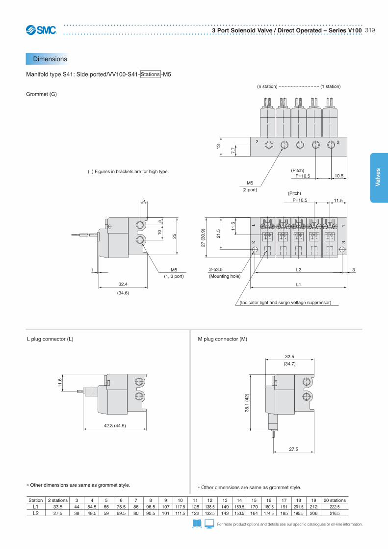
Dimensions
Series V100 – 3 Port Solenoid Valve / Direct Operated318
Valves
Manifold SpecificationsSeries V100
How to Order
Manifold Specifications Accessories
Product Recommendation
VV100-S41-02-M5
VV100-S41-03-M5
VV100-S41-04-M5
VV100-S41-05-M5
VV100-S41-06-M5
VV100-S41-07-M5
VV100-S41-08-M5
VV100-S41-09-M5
VV100-S41-10-M5
VV100-S41-12-M5
VV100-S41-18-M5
VV100-S41-20-M5
Stocked items for fast delivery/Manifolds
Series AN - Silencers - page 556Series AC - Air preparation - page 1076Series TU - Tubing - page 1223Series KQ2 - Fittings - page 1184
Related Products
Specifications
P (SUP)/R (EXH) type
Number of valves
Output portporting specifications
Port size
Type S41
Location
Direction
1, 2, 3 port
Common SUP/Common EXH
2 to 20 stations
Base
Side
M5
Note 1) V114(A) and V124(A) cannot be mounted onto the same manifold.Note 2) For V124(A), pressure from port 3 and exhaust from port 1.
Common SUP/Common EXH
Blanking Plate Assembly
Part no.: V100-77-1APlace notch mark on the blank plate to 2 port side when assembling.
Note: V114(A) and V124(A) cannot be mixed on manifolds.
VV100 S41 05Stations
02
20
2 stations
20 stations
M52 port size M5 M51 port
M53 port
M5
2 portM5
Gasket
Round head combination screw(M2 x 7, flat nickel plated)
Blanking plateNotch mark
1
2
3
1
2
2
3
•••
•••
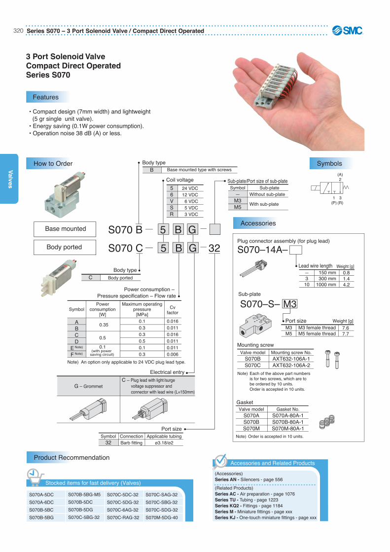
Series S070 – 3 Port Solenoid Valve / Compact Direct Operated320
Valves
3 Port Solenoid ValveCompact Direct OperatedSeries S070
56VSR
24 VDC12 VDC6 VDC5 VDC3 VDC
Coil voltage
Power consumption – Pressure specification – Flow rate
Electrical entry
Symbol32
ConnectionBarb fitting
Applicable tubingø3.18/ø2
Port size
Sub-plate/Port size of sub-plateSymbol
—M3M5
Sub-plateWithout sub-plate
With sub-plate
Body type
Body typeC Body ported
Note) An option only applicable to 24 VDC plug lead type.
G – GrommetC – Plug lead with light /surge voltage suppressor and connector with lead wire (L=150mm)
Symbol
ABCD
E Note)
F Note)
Powerconsumption
[W]
0.35
0.5
0.1
Maximum operatingpressure
[MPa]0.10.30.30.50.10.3
Cvfactor
0.0160.0110.0160.0110.0110.006
B Base mounted type with screws
S070 B 5 B G
S070 C 5 B G 32
(with power saving circuit)
(A)2
3(R)
1(P)
Plug connector assembly (for plug lead)
Lead wire length
S070–14A–
—310
150 mm300 mm
1000 mm
Sub-plate
Port size
S070–S– M3
M3M5
M3 female threadM5 female thread
GasketValve model
S070AS070BS070M
Gasket No.S070A-80A-1S070B-80A-1S070M-80A-1
Note) Order is accepted in 10 units.
Mounting screwValve model
S070BS070C
Mounting screw No.AXT632-106A-1AXT632-106A-2
Note) Each of the above part numbers is for two screws, which are to be ordered by 10 units. Order is accepted in 10 units.
Weight [g]0.81.44.2
Weight [g]
7.67.7
• Compact design (7mm width) and lightweight (5 gr single unit valve).• Energy saving (0.1W power consumption).• Operation noise 38 dB (A) or less.
Features
How to Order Symbols
Body ported
Base mountedAccessories
Product Recommendation
S070A-5DCS070A-6DCS070B-5BCS070B-5BG
S070B-5BG-M5S070B-5DCS070B-5DGS070C-5BG-32
S070C-5DC-32
S070C-5DG-32
S070C-6AG-32
S070C-RAG-32
S070C-SAG-32
S070C-SBG-32
S070C-SDG-32S070M-5DG-40
Stocked items for fast delivery (Valves)(Accessories)Series AN - Silencers - page 556
(Related Products)Series AC - Air preparation - page 1076Series TU - Tubing - page 1223Series KQ2 - Fittings - page 1184Series M - Miniature fittings - page xxxSeries KJ - One-touch miniature fittings - page xxx
Accessories and Related Products
3 Port Solenoid Valve / Compact Direct Operated – Series S070 321
Valv
es
For more product options and details see our specific catalogues or on-line information.
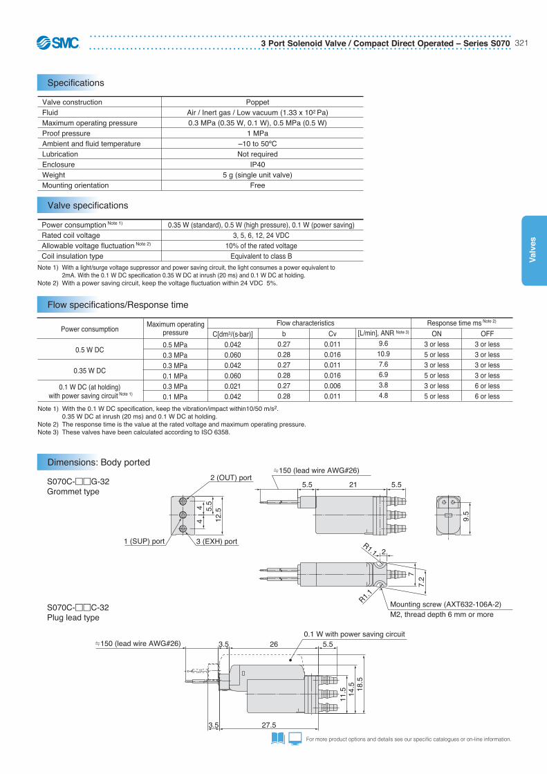
Valve constructionFluidMaximum operating pressureProof pressureAmbient and fluid temperature
LubricationEnclosureWeightMounting orientation
PoppetAir / Inert gas / Low vacuum (1.33 x 10² Pa)0.3 MPa (0.35 W, 0.1 W), 0.5 MPa (0.5 W)
1 MPa–10 to 50ºCNot required
IP405 g (single unit valve)
Free
Note 1) With a light/surge voltage suppressor and power saving circuit, the light consumes a power equivalent to 2mA. With the 0.1 W DC specification 0.35 W DC at inrush (20 ms) and 0.1 W DC at holding.Note 2) With a power saving circuit, keep the voltage fluctuation within 24 VDC 5%.
Note 1) With the 0.1 W DC specification, keep the vibration/impact within10/50 m/s2. 0.35 W DC at inrush (20 ms) and 0.1 W DC at holding.Note 2) The response time is the value at the rated voltage and maximum operating pressure.Note 3) These valves have been calculated according to ISO 6358.
Power consumption Note 1)
Rated coil voltageAllowable voltage fluctuation Note 2)
Coil insulation type
0.35 W (standard), 0.5 W (high pressure), 0.1 W (power saving)3, 5, 6, 12, 24 VDC
10% of the rated voltageEquivalent to class B
Power consumption
0.5 W DC
0.35 W DC
0.1 W DC (at holding) with power saving circuit Note 1)
C[dm3/(s•bar)]0.0420.0600.0420.0600.0210.042
0.5 MPa0.3 MPa0.3 MPa0.1 MPa0.3 MPa0.1 MPa
Flow characteristics Response time ms Note 2)
b0.270.280.270.280.270.28
Cv0.0110.0160.0110.0160.0060.011
ON3 or less5 or less3 or less5 or less3 or less5 or less
OFF3 or less3 or less3 or less3 or less6 or less6 or less
Maximum operatingpressure [L/min], ANR Note 3)
9.610.97.66.93.84.8
S070C-��G-32Grommet type
S070C-��C-32Plug lead type
18.5
14.5
11.5
27.5
150 (lead wire AWG#26) 3.5 26 5.5
150 (lead wire AWG#26)
5.5 21
7.2
2
R1.1
R1.1
9.5
7
5.5
12.55.
54
4
3.5
1 (SUP) port 3 (EXH) port
2 (OUT) port
Mounting screw (AXT632-106A-2)M2, thread depth 6 mm or more
0.1 W with power saving circuit
Specifications
Valve specifications
Flow specifications/Response time
Dimensions: Body ported
Series S070 – 3 Port Solenoid Valve / Compact Direct Operated322
Valves
S070B-��G-M3Grommet type S070B-��C-M3
Plug lead type
6
2623
.520
.59.
5
28.53.5
3.5 27
3
0.1 W with powersaving circuit6
21.5
9.5
6.5
19
25
12.3 10
4.5
5.5
10
163
1812
7
5.5 150 (lead wire AWG#26) 22
32
1
2 x ø3.4 Mounting hole
M33 (EXH) port
M31 (SUP) port
M32 (OUT) port
S070B-��G-M5Grommet type
S070B-��C-M5Plug lead type
6
2311
7
2512.3
20.5
12
56
12
16.53
2115
225.5
7
150 (lead wire AWG#26)
32
1
2 x ø3.4 Mounting hole
M53 (EXH) port
M52 (OUT) port
M51 (SUP) port
27.5
2522
11
28.53.5
63.5 27
3
0.1 W with powersaving circuit
Dimensions: Base mounted with sub-plate
3 Port Solenoid Valve / Compact Direct Operated – Series S070 323
Valv
es
For more product options and details see our specific catalogues or on-line information.
Manifold SpecificationsSeries S070 Base Mounted Manifold Stacking Base Type
Base Mounted ManifoldStacking Base
Port size
Grommet/Plug leadC
Electrical entry
Ports
Stations
3 port3
SS07 3 A01 08 C
2 stations3 stations
20 stations
0203
20
……
Note) Maximum of 20 stations
SUP/EXH port(Applicable tubing)
Barb fittings(ø6/ø4)
OUT portSymbol
A01A02
Barb fittings
Applicable tubing
ø3.18/ø2
ø4/ø2.5
Coil voltage
Electrical entryBody type
S070 A 5 B G
A Base mounted with clips
56VSR
24 VDC12 VDC6 VDC5 VDC3 VDC
GC
GrommetPlug lead with light/surge voltage suppressor and connector with lead wire (L=150mm)
Note) The outside and inside diameters of the “applicable tubing” are indicated for the barb fitting.
Power consumption – Pressure specification – Flow rate
Note) An option only applicable to 24 VDC plug lead type.
Symbol
ABCD
E Note)
F Note)
Powerconsumption
[W]
0.35
0.5
0.1
Maximum operatingpressure
[MPa]0.10.30.30.50.10.3
Cvfactor
0.0160.0110.0160.0110.0110.006
(with power saving circuit)
How to Order Manifold
How to Order Valves for manifold
Product Recommendation
SS073A01-02C
SS073A01-05C
SS073A01-07C
SS073A01-08C
SS073A01-12C
Stocked items for fast delivery (Manifold)
(Accessories)Series AN - Silencers - page 556
(Related Products)Series AC - Air preparation - page 1076Series TU - Tubing - page 1223Series KQ2 - Fittings - page 1184Series M - Miniature fittings - page xxxSeries KJ - One-touch miniature fittings - page xxx
Accessories and Related Products
Series S070 – 3 Port Solenoid Valve / Compact Direct Operated324
Valves
Base mounted manifold / Stacking base
SS073A - Stations C
nU side 12345 D side
12101.2104.8
19151.6155.2
Dimensions
L1L2
nL
Formulas: L1 = n x 7.2 + 14.8, L2 = n x 7.2 + 18.4, n: Stations (maximum 20 stations)
229.232.8
336.440
443.647.2
550.854.4
65861.6
765.268.8
872.476
979.683.2
1086.890.4
119497.6
13108.4112
14115.6119.2
15122.8126.4
16130133.6
17137.2140.8
18144.4148
20158.8162.4
12
R1.7
3.4
L111
1.8
725
.5
53.5
3.55
8
P = 7.2 12.8
(18)
7
3.2
L2
P = 7.2
n-ø3.2, ø4 barb fitting2 (OUT) port
ø6 barb fitting3 (EXH) port
ø6 barb fitting1 (SUP) port
28.5
3.5
150
(lead
wire
AW
G#2
6)27
3.5
23.521
3.5
0.1 W with power saving circuit
5.5
150
(lead
wire
AW
G#2
6)22
3.5
195
0102
Dimensions
3 Port Solenoid Valve / Compact Direct Operated – Series S070 325
Valv
es
For more product options and details see our specific catalogues or on-line information.
Base mounted manifold / Stacking base
SS073A - Stations C
nU side 12345 D side
12101.2104.8
19151.6155.2
Dimensions
L1L2
nL
Formulas: L1 = n x 7.2 + 14.8, L2 = n x 7.2 + 18.4, n: Stations (maximum 20 stations)
229.232.8
336.440
443.647.2
550.854.4
65861.6
765.268.8
872.476
979.683.2
1086.890.4
119497.6
13108.4112
14115.6119.2
15122.8126.4
16130133.6
17137.2140.8
18144.4148
20158.8162.4
12
R1.7
3.4
L111
1.8
725
.5
53.5
3.55
8
P = 7.2 12.8
(18)
7
3.2
L2
P = 7.2
n-ø3.2, ø4 barb fitting2 (OUT) port
ø6 barb fitting3 (EXH) port
ø6 barb fitting1 (SUP) port
28.5
3.5
150
(lead
wire
AW
G#2
6)27
3.5
23.521
3.5
0.1 W with power saving circuit
5.5
150
(lead
wire
AW
G#2
6)22
3.5
195
0102
Dimensions
Port size
Grommet/Plug leadC
Electrical entryPorts
SS07 3 B01 08 C
SUP/EXH port(Applicable tubing)
M5 female thread
OUT portSymbol
B01 M3 female thread
Applicable tubing–
Coil voltage
Electrical entry
3 port3
S070 B 5 B G
GC
GrommetPlug lead with light/surge voltage suppressor and connector with lead wire (L=300)
56VSR
24 VDC12 VDC
6 VDC5 VDC3 VDC
Stations2 stations3 stations
20 stations
0203
20
……
Note) Maximum of 20 stations
Body type
B Base mounted with screws
Power consumption – Pressure specification – Flow rate
Note) An option only applicable to 24 VDC plug lead type.
Symbol
ABCD
E Note)
F Note)
Powerconsumption
[W]
0.35
0.5
0.1
Maximum operatingpressure
[MPa]0.10.30.30.50.10.3
Cvfactor
0.0160.0110.0160.0110.0110.006
(with power saving circuit)
Manifold SpecificationsSeries S070 Base Mounted Manifold Bar Base Specification
Base Mounted ManifoldBar Base
How to Order Manifold
Product Recommendation
SS073B01-02C
SS073B01-04C
SS073B01-05C
SS073B01-06C
SS073B01-12C
Stocked items for fast delivery (Manifold)
(Accessories)Series AN - Silencers - page 556
(Related Products)Series AC - Air preparation - page 1076Series TU - Tubing - page 1223Series KQ2 - Fittings - page 1184Series M - Miniature fittings - page xxxSeries KJ - One-touch miniature fittings - page xxx
Accessories and Related Products
Series S070 – 3 Port Solenoid Valve / Compact Direct Operated326
Valves
Base mounted manifold / Bar base
SS073B01- Stations C
1295.2
101.2
19145.6151.6
Dimensions
L1L2
nL
Formulas: L1 = n x 7.2 + 8.8, L2 = n x 7.2 + 14.8, n: Stations (maximum 20 stations)2
23.229.2
330.436.4
437.643.6
544.850.8
65258
759.265.2
866.472.4
973.679.6
1080.886.8
118894
13102.4108.4
14109.6115.6
15116.8122.8
16124130
17131.2137.2
18138.4144.4
20152.8158.8
10.57
4.3
11.9 4.
0
21.5
22
5.5
150
(lead
wire
AW
G#2
6)22
3.9
(21.
5)(1
0.5)
22.5
6.4
8
11
4.3
P = 7.2
2418.9
L2L1 3
P = 7.2
31
31
2-ø3.4Mountinghole
2 2
n-M3 2 (OUT) port
2-M51 (SUP) port
2-M5 3 (EXH) port
nU side 12345 D side
Dimensions
3 Port Solenoid Valve / Compact Direct Operated – Series S070 327
Valv
es
For more product options and details see our specific catalogues or on-line information.
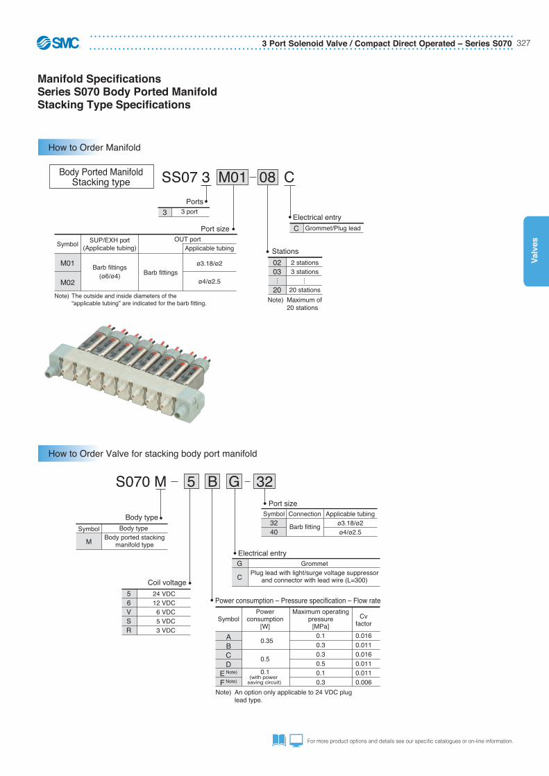
Manifold SpecificationsSeries S070 Body Ported Manifold Stacking Type Specifications
Port size Grommet/Plug leadC
Electrical entry3 port3
Ports
Stations
SS07 3 M01 08 C
2 stations3 stations
20 stations
0203
20
……
Note) Maximum of 20 stations
SUP/EXH port(Applicable tubing)
Barb fittings(ø6/ø4)
OUT portSymbol
M01
M02Barb fittings
Applicable tubing
ø3.18/ø2
ø4/ø2.5
Coil voltage
Power consumption – Pressure specification – Flow rate
Body type
Symbol
M
Body typeBody ported stacking
manifold type
Port size
Note) The outside and inside diameters of the “applicable tubing” are indicated for the barb fitting.
S070 M 5 B G 32
56VSR
24 VDC12 VDC6 VDC5 VDC3 VDC
Applicable tubingø3.18/ø2ø4/ø2.5
Symbol3240
Connection
Barb fitting
Note) An option only applicable to 24 VDC plug lead type.
Symbol
ABCD
E Note)
F Note)
Powerconsumption
[W]
0.35
0.5
0.1
Maximum operatingpressure
[MPa]0.10.30.30.50.10.3
Cvfactor
0.0160.0110.0160.0110.0110.006
(with power saving circuit)
Electrical entryG
C
GrommetPlug lead with light/surge voltage suppressor
and connector with lead wire (L=300)
Body Ported ManifoldStacking type
How to Order Manifold
How to Order Valve for stacking body port manifold
Series S070 – 3 Port Solenoid Valve / Compact Direct Operated328
Valves
Body ported stacking type manifold
SS073M - Stations C
1293.4101.4
19143.8151.8
Dimensions
L1L2
nL
Formulas: L1 = n x 7.2+ 7, L2 = n x 7.2 + 15, n: Stations (maximum 20 stations)2
21.429.4
328.636.6
435.843.8
54351
650.258.2
757.465.4
864.672.6
971.879.8
107987
1186.294.2
13100.6108.6
14107.8115.8
15115123
16122.2130.2
17129.4137.4
18136.6144.6
20151159
nU side 12345 D side
16.533
3.5
31.5
3.5
150
(lead
wire
AW
G#2
6)
14.512.5
150
(lead
wire
AW
G#2
6)5.
526
.5 16.5
8
13.1
3.4
9.5
5.5
(11.
5)
59.
5
6.8
8.3
3.8
P = 7.2 7.7 3.4
L2L1
P = 7.2 47.1
0.1 W with power saving circuit
1
2-ø3.4Mounting hole
n-ø3.2, ø4 barb fitting2 (OUT) port
ø6 barb fitting1 (SUP) port
ø6 barb fitting3 (EXH) port
0102
3Dimensions
3 Port Solenoid Valve / Compact Direct Operated – Series S070 329
Valv
es
For more product options and details see our specific catalogues or on-line information.
Body ported stacking type manifold
SS073M - Stations C
1293.4101.4
19143.8151.8
Dimensions
L1L2
nL
Formulas: L1 = n x 7.2+ 7, L2 = n x 7.2 + 15, n: Stations (maximum 20 stations)2
21.429.4
328.636.6
435.843.8
54351
650.258.2
757.465.4
864.672.6
971.879.8
107987
1186.294.2
13100.6108.6
14107.8115.8
15115123
16122.2130.2
17129.4137.4
18136.6144.6
20151159
nU side 12345 D side
16.5
333.
5
31.5
3.5
150
(lead
wire
AW
G#2
6)
14.512.5
150
(lead
wire
AW
G#2
6)5.
526
.5 16.5
8
13.1
3.4
9.5
5.5
(11.
5)
59.
5
6.8
8.3
3.8
P = 7.2 7.7 3.4
L2L1
P = 7.2 47.1
0.1 W with power saving circuit
1
2-ø3.4Mounting hole
n-ø3.2, ø4 barb fitting2 (OUT) port
ø6 barb fitting1 (SUP) port
ø6 barb fitting3 (EXH) port
0102
3
Dimensions
Blanking plate assembly (for SS073A)
SS070A-10A (for separable base)
Blanking plate assembly (for SS073B)
SS070B-10A (for bar base)
Intermediate block assembly (for SS073A)
SS070A-B (for separable base)
7
12
7
21.5
Intermediate block
assembly
Intermediate block
assembly
Valve
2 (A)
Valve
1 (P)3 (R)
2 (A)
U sideD side
U sideD side
16
7.2
25.5
7
ø3.4Mountinghole
Clip
Metal joint
Intermediate block assembly
Intermediate block assembly
Intermediate block assembly (for SS073M)
SS070M-B (for stacking type) Valve
2 (A)
Valve
1 (P)3 (R)
2 (A)
Clip
Gasket
13.1
9.5
7.2
11.55
ø3.4Mountinghole
This assembly is mounted on a manifold block where the valve is removed for maintenance or a replacement valve is going to be mounted.
This assembly is used to secure the manifold when a large number of stations are manifolded. (Accommodated as one station.)∗ In the manifold specification sheet, specify the position where the block assembly is mounted.
This assembly is used to secure the manifold when 20 or more stations are manifolded. (Accommodated as one station.)∗ In the manifold specification sheet, specify the position where the block assembly is mounted.
This assembly is mounted on a manifold block where the valve is removed for maintenance or a replacement valve is going to be mounted.
No.SS070A-10A
Weight [g]0.7
NameBlanking plate
No.SS070B-10A
Weight [g]1.3
NameBlanking plate
No.SS070A-B
Weight [g]1.5
NameIntermediate block
No.SS070M-B
Weight [g]1.2
NameBlanking plate
Manifold Options
Series SYJ300/500/700 – 3 Port Pilot Solenoid Valve330
Valves
3 Port Pilot Operated Solenoid ValveRubber SealSeries SYJ300/500/700
• Micro design.• Energy saving (0.1W power consumption).• N.O. or N.C. options.• Design life of 50 Million switching cycles.
SYJ 3 2 5 M M3
SYJ 3 4 5 M
1
1
12
Normally closedNormally open
Type of actuation
56VSR
24 VDC12 VDC
6 VDC5 VDC3 VDC
Rated voltageDC
Body option—: Individual pilot exhaust type
M: Common exhaust for the pilot and main valve
R: External pilot type∗
In SYJ300, pilot valveexhaust is centralisedto main valve.
∗ SYJ��2R is only for manifold use.
—ZU
Without light/surge voltage suppressorWith light/surge voltage suppressor
With light/surge voltage suppressor (Non-polar type)
Light/Surge voltage suppressor
Manual override
—: Non-locking push type
D: Push-turn locking slotted type
E: Push-turn locking lever type
Electrical entry
G: Lead wire length 300 mm
L: With lead wire (Length 300 mm)
M: With lead wire (Length 300 mm)
WO: Without connector cable
LO: Without connector
MO: Without connector
24, 12, 6, 5, 3 VDC
Grommet L plug connector M plug connector M8 connectorR port P, E port
R port P, E port
–+–+
+–
D: With connector
DIN terminal
Note: Not applicable for SYJ300
357
SYJ300SYJ500SYJ700
Valve size
M3M501F
M3M5
G1/8
Port sizeSYJ300SYJ500SYJ700
Q
Q
Internal pilot
SYJ3124 SYJ32 2
4
External pilot
SYJ31 R24 SYJ32 R2
4X X(A)2
(A)2
1(P)
3(R)
(A)2
1(P)
3(R)
1(P)
3(R)
(A)2
1(P)
3(R)
R
NRTL /C
®
For connector cables, please see the cables appendix.
Features
How to Order
Symbols
Body ported
Base mounted
24, 12, 6, 5, 3 VDC24, 12 VDC
DO: Without connector
SYJ300SYJ500SYJ700
20,212020
Valve Manifold type
SYJ300SYJ500SYJ700
41, S41, 42, S4240, 4140, 41, 42
Valve Manifold type
For sub-plate type
3 Port Pilot Solenoid Valve – Series SYJ300/500/700 331
Valv
es
For more product options and details see our specific catalogues or on-line information.
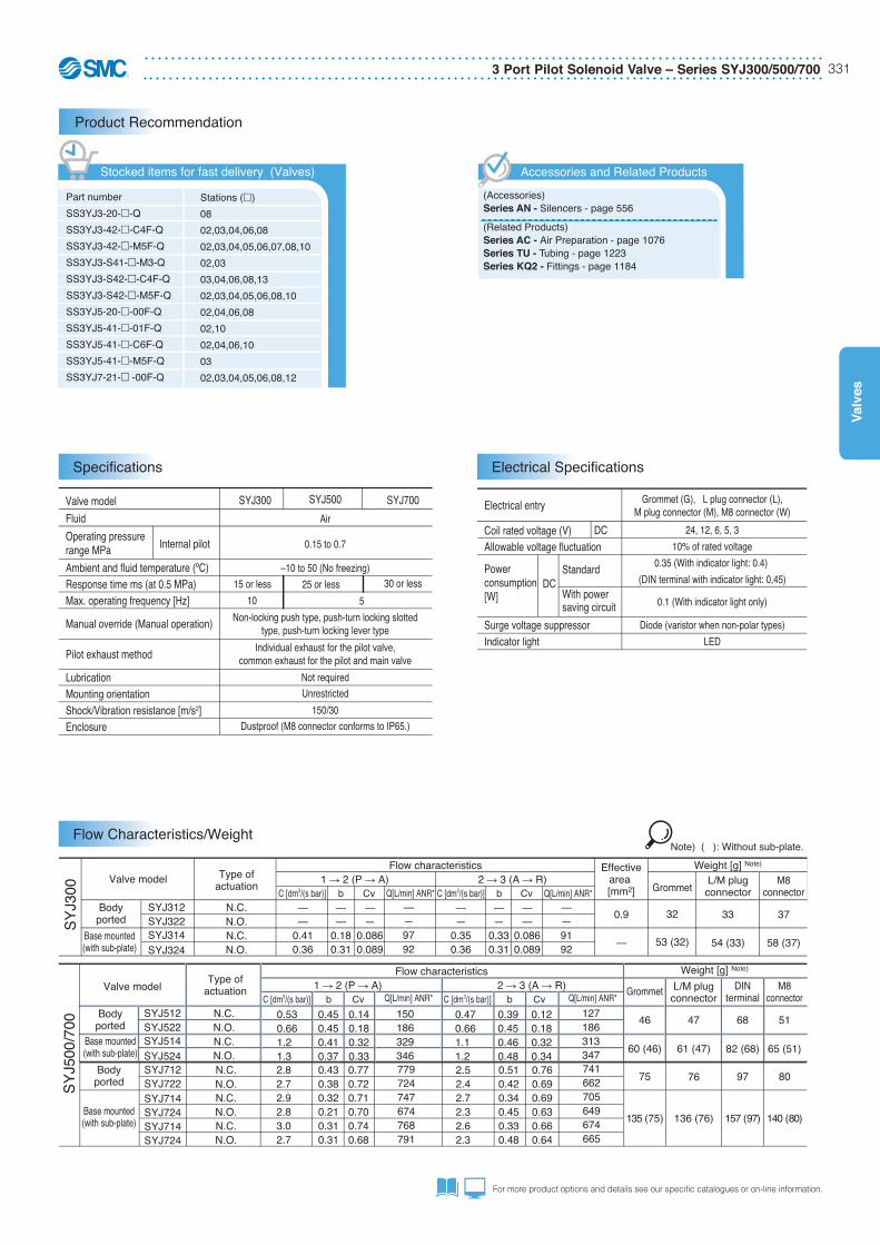
Fluid
Operating pressure range MPa
Ambient and fluid temperature (ºC)Response time ms (at 0.5 MPa)Max. operating frequency [Hz]
Pilot valve pressure is supplied separately from the main valve pressure through the use of a separate supply port.It can be used in the vacuum (up to –100 kPa) or low pressure line with 0.15 MPa or less.
Note 1) External pilot type body ported valves (SYJ��2R) can only be used on the manifold.
External Pilot
3 Port Pilot Solenoid Valve – Series SYJ300/500/700 333
Valv
es
For more product options and details see our specific catalogues or on-line information.
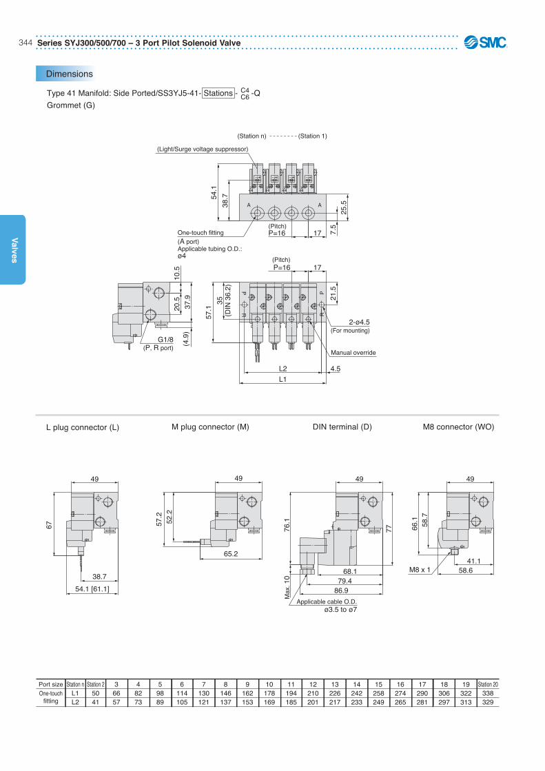
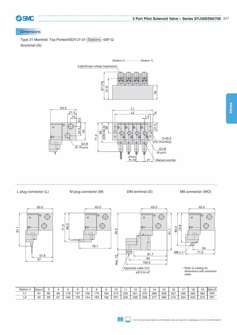
Body Ported
Grommet (G): SYJ5�2-�G ��-M5-Q
With bracket: SYJ5�2-�G ��-M5-Q
L plug connector (L):SYJ5�2-�L��-M5-Q
M plug connector (M):SYJ5�2-�M��-M5-Q
DIN terminal (D):SYJ5�2-�D��-M5-Q
M8 connector (MO):SYJ5�2-�WO��-M5-Q
50.7
39.2
28.1
57.264
.6
15.1
32.6Max
. 10
74.6
60.9
53.4
42.1
27
89
14.5 3
23
20
12.7
89
14.5 3
23
20
89
14.5 3
23
20
M8 x 1
Applicable cable O.D. ø3.5 to ø7
34.7
75.5
89
3
23
14.5
20
65.5
55.7
2.3
55.6
12.7
28.1
23 7
2-ø3.5(For mounting)
2518
3.5
37
30
-+
(Bracket)
1115
12.7
28.1 55.6
2.5
89
14.5
3
23 20
15.5
8.513
1111.5 ø1.4(PE port)
M5 (P, R port)
33.5
2-ø2.6(For mounting)
M5(A port)
G: Approx. 300(Lead wire length)
- +
RP
A
(Light/Surge voltage suppressor)
Manual override
2-ø2.6(For manifold mounting)
Dimensions
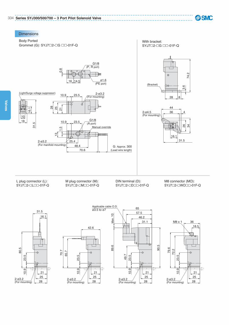
Series SYJ300/500/700 – 3 Port Pilot Solenoid Valve334
Valves
Body PortedGrommet (G): SYJ7�2-�G ��-01F-Q
With bracket: SYJ7�2-�G ��-01F-Q
L plug connector (L):SYJ7�2-�L��-01F-Q
M plug connector (M):SYJ7�2-�M��-01F-Q
DIN terminal (D):SYJ7�2-�D��-01F-Q
M8 connector (MO):SYJ7�2-�WO��-01F-Q
31.5
0.8
1.5
70.6
14.516
23.510.9
48.4
25.4
13
23.510.9
16.1
18
10
28 25 21
ø1.6(PE port)
2-ø3.2(For mounting)
G: Approx. 300(Lead wire length)
G1/8(A port)
(Light/Surge voltage suppressor)
G1/8(P, R port)
Manual override
2-ø3.2(For manifold mounting)
- +
RP
A
74.2
28
26
31.516.1
8
3.6(Bracket)
2-ø4.5(For mounting)
4
34
44
36
+-
42.6
79.6
72.2
18.5
23.5
10.9
31.1
23.5
10.9
Applicable cable O.D. ø3.5 to ø7
2-ø3.2(For mounting)
2-ø3.2(For mounting)
M8 x 1 36
65
46.2
57.5
Max
. 10
89.6
90.5
49.7
28
25
21
28
25
21
23.5
10.9
31.5
16.1
23.5
10.9
80.5
70.7
65.7
2-ø3.2(For mounting)
2-ø3.2(For mounting) 28
25
21
28
25
21
Dimensions
3 Port Pilot Solenoid Valve – Series SYJ300/500/700 335
Valv
es
For more product options and details see our specific catalogues or on-line information.
Manifold SpecificationsSeries SYJ300/500/700
A
A
P
R
A
–+–+
–+–+
R
P
PR
Type 20
Type 41
Type 42
Type 41 Type S41Pilot valve is on the A port side.
Stocked items for fast delivery (Valves for Manifold)
VO307Y-5DZ1-Q
Specifications
Valve Options
Note 1) Values for a single valve unit. It is not applicable to the manifold. Refer to the manifold specifications.Note 2) These valves have beel calculated according to ISO 6368.
Specifications different from standard are as follows.Operating pressure range –101.2 kPa to 0.1 MPa
Specifications different from standard are as follows.
Type of actuationFluidOperating pressure rangeAmbient and fluid temperatureResponse timeMax. operating frequencyLubricationManual overrideMounting orientationImpact/Vibration resistanceEnclosure
Direct operated type 2 position single solenoidAir
0 to 1 MPa (High-pressure type), 0 to 0.7 MPa (Standard type)–10 to 50°C (No freezing)20 ms or less (at 0.5 MPa)
10 HzNot required (Use turbine oil Class 1 ISO VG32, if lubricated.)
Non-locking push typeUnrestricted150/50 m/s2
Dustproof
Electrical entry
Coil rated voltage [V]
Allowable voltage fluctuation
Apparent power AC
DCACDC
DCAC (50/60 Hz)
InrushHolding
DIN terminal24, 100, 110, 200, 220, 240
12, 24–15 to +10% of rated voltage
12.7 VA (50 Hz), 10.7 VA (60 Hz) 7.6 VA (50 Hz), 5.4 VA (60 Hz)
Series VT307/VT317 – 3 Port Solenoid Valve / Direct Operated Poopet Type352
Valves
Dimensions
54.5
(3.2
)
10.3
33.2
16.5
Max
. 10
67.6
13.5
29.5
16.7
1
3
25.6
13 2
Pg9
25
18.6
M4 x 0.7 thread depth 7(Mounting screw)
G1/4", G1/8"(Piping port)
(14.5)
(37)
(28)(4.5)
(4.5
)
(42)
(33)
(17.
2)
Applicable cable O.D.ø6 to ø8
Manual override(Non-locking)
2 x ø4.5(For mounting)
65
56
DIN terminal: VT307-�D1
3 Port Solenoid Valve / Direct Operated Poopet Type – Series VT307/VT317 353
Valv
es
For more product options and details see our specific catalogues or on-line information.
Dimensions
54.5
(3.2
)
10.3
33.2
16.5
Max
. 10
67.6
13.5
29.5
16.7
1
3
25.6
13 2
Pg9
25
18.6
M4 x 0.7 thread depth 7(Mounting screw)
G1/4", G1/8"(Piping port)
(14.5)
(37)
(28)(4.5)
(4.5
)
(42)
(33)
(17.
2)
Applicable cable O.D.ø6 to ø8
Manual override(Non-locking)
2 x ø4.5(For mounting)
65
56
DIN terminal: VT307-�D1
Manifold SpecificationsSeries VT307
How to Order Manifold Base
RoHS
Exhaust port type23
Common exhaustIndividual exhaust
Valve stations
VV307
2 stations
20 stations
02
20
05 2 01F
01F02F
A port size (Base mounted)VT307 manifold
Dummy symbolMounting bracket
01 F
Max. 20 stations
Note) For 6 stations or more, supply air both sides of P port. The common exhaust type should exhaust from both of the R port.
Common exhaustVV307-01-052-�-F
Individual exhaustVV307-01-053-�-F
Manifold typeMax. number of stationsApplicable solenoid valve
B mount20 stations Note)
VO307�-���� -Q
Exhaust portSymbol
2
3
Type
Common
Individual
Port location (Direction)/Port sizeP RA
··· ···
G common exhaust/individual exhaust1 8
G individual exhaust1 4
Base (Side)1 8
Base (Side)1 4
Base (Top)1 8
Base (Side)1 8
Base (Side)1 8
Base (Side)1 8 1 4,
Manifold Specifications
Description Part no.Function plate (With gasket) Note)
Mounting screws NXT013-3
Qty.1 pc.2 pcs.
Note) DXT060-51-13B, DXT152-14-1B are for the continuous duty type.
Description Part no.Blanking plate (With gasket, screw) Note)
C[dm3/(s·bar)]
0.34
0.30
b
0.28
0.18
Cv
0.089
0.070
Weight
Grommet
0.15 kg
Valve model
VO307VO307V (Vacuum spec. type)
VO307E (Continuous duty type)
VO307Y (Energy-saving type)
VO307W (Energy-saving, Vacuum spec. type)
C [dm3/(s·bar)]
0.34
0.30
b
0.22
0.15
Cv
0.082
0.072
Flow-rate characteristics1 → 2 (P → A) 2 → 3 (A → R)
DXT060-51-13 AB
DXT152-14-1 AB
Blanking Plate
Accessories
Flow-rate Characteristics
Weight
Grommet
0.15 kg
Valve model
VO307VO307V (Vacuum spec. type)
VO307E (Continuous duty type)
VO307Y (Energy-saving type)
VO307W (Energy-saving, Vacuum spec. type)
C [dm3/(s·bar)]
0.36
0.32
b
0.28
0.20
Cv
0.091
0.075
C[dm3/(s·bar)]
0.34
0.30
b
0.18
0.15
Cv
0.080
0.069
Flow-rate characteristics3 → 2 (R → A) 2 → 1 (A → P)
* These valves have beel calculated according to ISO 6368.
Q [L/min] (ANR)*
85
71
Q [L/min] (ANR)*
82
70
Q [L/min] (ANR)*
90
77
Q [L/min] (ANR)*
81
70
Series VT307/VT317 – 3 Port Solenoid Valve / Direct Operated Poopet Type354
Valves
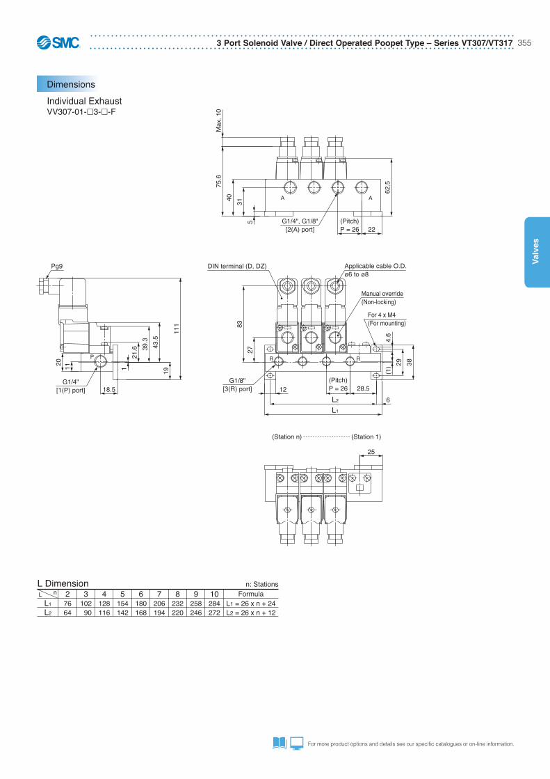
Dimensions
Common Exhaust
nL
L1
L2
28862
3114 88
4140114
5166140
6192166
7218192
8244218
9270244
10296270
FormulaL1 = 26 x n + 36L2 = 26 x n + 10
n: StationsL Dimension
VV307-01-�2-01-F
83
26.7
38294.
6
12 18
13L2
L1
DIN terminal (D, DZ)
Manual override(Non-locking)
111
43.5
39.3
21.6
19
1
209
20 13
Pg9
G1/8"[1(P), 3(R) port]
For 4 x M4(For mounting)
Applicable cable O.D.ø6 to ø8
(Pitch)P = 26
(Station n) (Station 1)
PR
PR
64
Max
. 10
77.1
(35)
31
40
235
G1/8"[2(A) port]
(Pitch)P = 26
A A
3 Port Solenoid Valve / Direct Operated Poopet Type – Series VT307/VT317 355
Valv
es
For more product options and details see our specific catalogues or on-line information.
Dimensions
Common Exhaust
nL
L1
L2
28862
3114 88
4140114
5166140
6192166
7218192
8244218
9270244
10296270
FormulaL1 = 26 x n + 36L2 = 26 x n + 10
n: StationsL Dimension
VV307-01-�2-01-F
83
26.7
38294.
6
12 18
13L2
L1
DIN terminal (D, DZ)
Manual override(Non-locking)
111
43.5
39.3
21.6
19
1
209
20 13
Pg9
G1/8"[1(P), 3(R) port]
For 4 x M4(For mounting)
Applicable cable O.D.ø6 to ø8
(Pitch)P = 26
(Station n) (Station 1)
PR
PR
64
Max
. 10
77.1
(35)
31
40
235
G1/8"[2(A) port]
(Pitch)P = 26
A A
Dimensions
Individual ExhaustVV307-01-�3-�-F
nL
L1
L2
27664
3102 90
4128116
5154142
6180168
7206194
8232220
9258246
10284272
FormulaL1 = 26 x n + 24L2 = 26 x n + 12
n: StationsL Dimension
25
3829
4.6
83
27
12
L1
L2
28.5
6
(1)
For 4 x M4(For mounting)
G1/8"[3(R) port]
DIN terminal (D, DZ)
(Pitch)P = 26
Applicable cable O.D.ø6 to ø8
Manual override(Non-locking)
R R
1
111
19
43.5
39.3
21.6
18.5
2011
Pg9
G1/4"[1(P) port]
P
62.5
Max
. 10
75.6
40
3122
5 G1/4", G1/8"[2(A) port]
(Pitch)P = 26
AA
(Station n) (Station 1)
Series VT307/VT317 – 3 Port Solenoid Valve / Direct Operated Poopet Type356
Valves
3 Port Direct OperatedPoppet Type-Rubber SealBody poted 1/4Series EVT317 (VT317)
Features
Symbol
How to Order
EVT317-3D-02F-Q
EVT317-3DO-02F-Q
EVT317-3DZ-02F-Q
EVT317-4D-02F-Q
EVT317-4DO-02F-Q
EVT317-4DZ-02F-Q
EVT317-5D-02F-Q
EVT317-5DO-02F-Q
EVT317-5DZ-02F-Q
EVT317-6D-02F-Q
EVT317-6DO-02F-Q
EVT317-6DZ-02F-Q
EVT317-BD-02F-Q
EVT317-BDO-02F-Q
EVT317-BDZ-02F-Q
EVT317E-5D-02F-Q
EVT317E-5DO-02F-Q
EVT317E-5DZ-02F-Q
EVT317V-4DO-02F-Q
EVT317V-5DO-02F-Q
EVT317V-5DZ-02F-Q
EVT317V-BDO-02F-Q
Product Recommendation
Stocked items for fast delivery/Body Ported Valves
VO317-3DO-Q
VO317-4DO-Q
VO317-5DO-Q
VO317-5DZ-Q
VO317E-5DZ-Q
VO317V-5DO-Q
VO317V-5D-Q
Stocked items for fast delivery/Valves for Manifold
Series AN - Silencers - page 556Series AC - Air preparation - page 1076Series TU - Tubing - page 1223Series KQ2 - Fittings - page 1184
Related Products
• 3 Port Poppet valve.• Robust construction.• Universal porting.• Suitable for vacuum applications.
Body type
EVT Body portedVO For Manifold
3 1 7 02F5 DEVT Q
02F
Without port (For manifold)—
G1 4
Port size
Light/Surge voltage suppressor
— None
Z With light/surge voltage suppressor
Valve option
— Standard typeContinuous duty type
123456
100 VAC, Hz200 VAC, Hz110 VAC, Hz
220, 230 VAC, Hz24 VDC12 VDC
7 240 VAC, HzB 24 VAC
Rated voltage50 6050 6050 60
50 60
50 60
(A)2
3(R)
1(P)
Body size
1 Body ported1 4
Note: Part numbering for Europe is EVT317. The Japanese standard series is VT317, the only difference is the Rc (taper thread) port in the Japanese version.
The manifold mounted valves VO317 do not use the E prefix.
Electrical entryD DIN connector (with connector)
DO DIN connector (without connector)
EY Energy savingV VacuumW Energy saving/Vacuum
3 Port Solenoid Valve / Direct Operated Poopet Type – Series VT307/VT317 357
Valv
es
For more product options and details see our specific catalogues or on-line information.
3 Port Direct OperatedPoppet Type-Rubber SealBody poted 1/4Series EVT317 (VT317)
Features
Symbol
How to Order
EVT317-3D-02F-Q
EVT317-3DO-02F-Q
EVT317-3DZ-02F-Q
EVT317-4D-02F-Q
EVT317-4DO-02F-Q
EVT317-4DZ-02F-Q
EVT317-5D-02F-Q
EVT317-5DO-02F-Q
EVT317-5DZ-02F-Q
EVT317-6D-02F-Q
EVT317-6DO-02F-Q
EVT317-6DZ-02F-Q
EVT317-BD-02F-Q
EVT317-BDO-02F-Q
EVT317-BDZ-02F-Q
EVT317E-5D-02F-Q
EVT317E-5DO-02F-Q
EVT317E-5DZ-02F-Q
EVT317V-4DO-02F-Q
EVT317V-5DO-02F-Q
EVT317V-5DZ-02F-Q
EVT317V-BDO-02F-Q
Product Recommendation
Stocked items for fast delivery/Body Ported Valves
VO317-3DO-Q
VO317-4DO-Q
VO317-5DO-Q
VO317-5DZ-Q
VO317E-5DZ-Q
VO317V-5DO-Q
VO317V-5D-Q
Stocked items for fast delivery/Valves for Manifold
Series AN - Silencers - page 556Series AC - Air preparation - page 1076Series TU - Tubing - page 1223Series KQ2 - Fittings - page 1184
Related Products
• 3 Port Poppet valve.• Robust construction.• Universal porting.• Suitable for vacuum applications.
Body type
EVT Body portedVO For Manifold
3 1 7 02F5 DEVT Q
02F
Without port (For manifold)—
G1 4
Port size
Light/Surge voltage suppressor
— None
Z With light/surge voltage suppressor
Valve option
— Standard typeContinuous duty type
123456
100 VAC, Hz200 VAC, Hz110 VAC, Hz
220, 230 VAC, Hz24 VDC12 VDC
7 240 VAC, HzB 24 VAC
Rated voltage50 6050 6050 60
50 60
50 60
(A)2
3(R)
1(P)
Body size
1 Body ported1 4
Note: Part numbering for Europe is EVT317. The Japanese standard series is VT317, the only difference is the Rc (taper thread) port in the Japanese version.
The manifold mounted valves VO317 do not use the E prefix.
Electrical entryD DIN connector (with connector)
DO DIN connector (without connector)
EY Energy savingV VacuumW Energy saving/Vacuum
Universal Porting
3-waynormallyclosed
3-waynormally
open
2-waynormallyclosed
2-waynormally
openSelector DiverterValve
function
De-energized
Energized
(Plugged)
(Plugged)
(Plu
gged
)(P
lugg
ed)
Specifications
Flow Characteristics/Weight for EVT317
Fluid
Ambient and fluid temperatureResponse time
Lubrication
Enclosure
Air
–10 to 50°C (No freezing)
Type of actuation Direct operated type 2 position single solenoid
Operating pressure range 0 to 0.9 MPa
Not required (Use turbine oil Class 1 ISO VG32, if lubricated.)Max. operating frequency 10 Hz
Mounting orientation UnrestrictedDustproof
Electrical entry
Coil rated voltage [V]
Allowable voltage fluctuation
Apparent power AC
DC
DCAC (50/60 Hz)
InrushHolding
DIN terminal24, 100,110, 200, 220, 240
12, 24–15 to +10% of rated voltage
Power consumption
Valve model EVT317, VO317
30 ms or less (at the pressure of 0.5 MPa)
11 VA (50 Hz) Without indicator light: 6 W, With indicator light: 6.3 W
19 VA (50 Hz)
C [dm3/(sbar)] C [dm3/(sbar)] C [dm3/(sbar)] C [dm3/(sbar)]b Cv
Weight
Grommet
0.29 kg
Valve model
EVT317EVT317E (Continuous duty type)
b Cv b Cv b Cv
Flow characteristics1 � 2 (P � A) 2 � 3 (A � R) 3 � 2 (R � A) 2 � 1 (A � P)
Note) Values for a single valve unit. It differs in the manifold case. Refer to manifold specifications .
Series VT307/VT317 – 3 Port Solenoid Valve / Direct Operated Poopet Type358
Valves
Product Recommendation
Manifold SpecificationsSeries EVT317
Specifications
Blanking Plates
EVV317-02-051-02
VO317 manifold valve can be easily converted from N.C.(Normally Closed) to N.O. (Normally Open) by rotatingthe valve 180° on the manifold.
Exhaust port type
3 Individual exhaust (see table below)
Valve stations
2 stations
20 stations
··· ···
02
20 0102
common exhaust/individual exhaust (for V0307 only)1 8
individual exhaust1 4
A port size (Base mounted)
Max. 20 stations.
Manifold typeMax. number of stations
B mount20 stations Note 1)
Exhaust portSymbol
3
1
Type
Individual
Port location (Direction)/Port sizeP
Base (Side)1 4
R
Base (Top)1
A
Base (Side)1 4
Description Part no.Blanking plate (With gasket, screw) PVT317-53-1A
1 Common exhaust
EVV317 05 102 02 FManifold for VO317
Base (Side)1 4
Common Note 2)Base (Side)
( )1 4 3 8
Base (Side)( )1 4 3 8
EVV317-02-021-02F
EVV317-02-023-02F
EVV317-02-031-02F
EVV317-02-041-02F
EVV317-02-061-02F
EVV317-02-101-02F
Stocked items for fast delivery/Manifold
4
Note 1) If operating with 3 valves or more, apply supply pressure to both of the P ports of the manifold. The common exhaust style should exhaust from both of the R ports.Note 2) If the case of common exhaust type, R and P port sizes can be 3/8 by using a mounting adaptor.
How to order
Flow Characteristics/Weight
C [dm3/(s·bar)]
2.0
b
0.11
Cv
0.47
Weight
GrommetValve model
VO317VO317E (Continuous duty type)
C [dm3/(s·bar)]
2.2
b
0.12
Cv
0.49
C [dm3/(s·bar)]
2.0
b
0.14
Cv
0.45
C [dm3/(s·bar)]
2.1
b
0.14
Cv
0.48
Flow characteristics1 � 2 (P � A) 2 � 3 (A � R) 3 � 2 (R � A) 2 � 1 (A � P)
0.32 kg
3 Port Solenoid Valve / Direct Operated Poopet Type – Series VT307/VT317 359
Valv
es
For more product options and details see our specific catalogues or on-line information.
Product Recommendation
Manifold SpecificationsSeries EVT317
Specifications
Blanking Plates
EVV317-02-051-02
VO317 manifold valve can be easily converted from N.C.(Normally Closed) to N.O. (Normally Open) by rotatingthe valve 180° on the manifold.
Exhaust port type
3 Individual exhaust (see table below)
Valve stations
2 stations
20 stations
··· ···
02
20 0102
common exhaust/individual exhaust (for V0307 only)1 8
individual exhaust1 4
A port size (Base mounted)
Max. 20 stations.
Manifold typeMax. number of stations
B mount20 stations Note 1)
Exhaust portSymbol
3
1
Type
Individual
Port location (Direction)/Port sizeP
Base (Side)1 4
R
Base (Top)1
A
Base (Side)1 4
Description Part no.Blanking plate (With gasket, screw) PVT317-53-1A
1 Common exhaust
EVV317 05 102 02 FManifold for VO317
Base (Side)1 4
Common Note 2)Base (Side)
( )1 4 3 8
Base (Side)( )1 4 3 8
EVV317-02-021-02F
EVV317-02-023-02F
EVV317-02-031-02F
EVV317-02-041-02F
EVV317-02-061-02F
EVV317-02-101-02F
Stocked items for fast delivery/Manifold
4
Note 1) If operating with 3 valves or more, apply supply pressure to both of the P ports of the manifold. The common exhaust style should exhaust from both of the R ports.Note 2) If the case of common exhaust type, R and P port sizes can be 3/8 by using a mounting adaptor.
How to order
Flow Characteristics/Weight
C [dm3/(s·bar)]
2.0
b
0.11
Cv
0.47
Weight
GrommetValve model
VO317VO317E (Continuous duty type)
C [dm3/(s·bar)]
2.2
b
0.12
Cv
0.49
C [dm3/(s·bar)]
2.0
b
0.14
Cv
0.45
C [dm3/(s·bar)]
2.1
b
0.14
Cv
0.48
Flow characteristics1 � 2 (P � A) 2 � 3 (A � R) 3 � 2 (R � A) 2 � 1 (A � P)
0.32 kg
Note: Grommet, Grommet terminal and conduit terminal valve types shown, are not available in Europe.
Dimensions: Common Exhaust
Without mounting bracket: VV317-02-�1-02
A A
R P
P=46
P=4627 35
50
73.5
49.5
L27.5L1
37.5
2450
15
57.745.2
20.2
32.7
136.
6
StationsL
L1
L2
2121106
3167152
4213198
5259244
6305290
7351336
8397382
9443428
10489474
FormulaL1= 46 x n + 29L2= 46 x n + 14
n: StationsL Dimension
Series VT307/VT317 – 3 Port Solenoid Valve / Direct Operated Poopet Type360
Valves
Note: Grommet, Grommet terminal and conduit terminal valve types shown, are not available in Europe.
Note: Grommet, Grommet terminal and conduit terminal valve types shown, are not available in Europe.
Dimensions: Individual Exhaust
Dimensions: Common Exhaust
L Dimension
With mounting adaptor: VV317-02-�1-02-A
StationsL
L1
L2
2181151
3227197
4273243
5319289
6365335
7411381
8457427
9503473
10549519
FormulaL1= 46 x n + 89L2= 46 x n + 59
n: Stations
15
65
L2L1
R P
28
80
20
52
57.745.2
A A
P=4679.567.5
32 4055
78.5
P=46
141.
6
20.2 32
.7
L Dimension
Without mounting bracket/VV317-02-�3-02
StationsL
L1
L2
2121106
3167152
4213198
5259244
6305290
7351336
8397382
9443428
10489474
FormulaL1 = 46 x n + 29L2 = 46 x n + 14
n: Stations
P
57.745.2
L27.5L1
50
15
12
20.2 32
.7
R
A
R
A
A
P=46
27 3550
73.5
37.5
136.
6
34 P=4618
3 Port Solenoid Valve / Direct Operated Poopet Type – Series EVT325 361
Valv
es
For more product options and details see our specific catalogues or on-line information.
Note: Grommet, Grommet terminal and conduit terminal valve types shown, are not available in Europe.
Note: Grommet, Grommet terminal and conduit terminal valve types shown, are not available in Europe.
Dimensions: Individual Exhaust
Dimensions: Common Exhaust
L Dimension
With mounting adaptor: VV317-02-�1-02-A
StationsL
L1
L2
2181151
3227197
4273243
5319289
6365335
7411381
8457427
9503473
10549519
FormulaL1= 46 x n + 89L2= 46 x n + 59
n: Stations
15
65
L2L1
R P
28
80
20
52
57.745.2
A A
P=4679.567.5
32 4055
78.5
P=46
141.
6
20.2 32
.7
L Dimension
Without mounting bracket/VV317-02-�3-02
StationsL
L1
L2
2121106
3167152
4213198
5259244
6305290
7351336
8397382
9443428
10489474
FormulaL1 = 46 x n + 29L2 = 46 x n + 14
n: Stations
P
57.745.2
L27.5L1
50
15
12
20.2 32
.7
R
A
R
A
A
P=46
27 3550
73.5
37.5
136.
6
34 P=4618
Fluid
Ambient and fluid temperatureMax. operating frequency
LubricationManual overrideEnclosure
Air
–10 to 50°C (No freezing.)
Type of actuation Direct operated type 2 position single solenoid
Operating pressure range 0 to 1.0 MPa
5 Hz
Not required (Use turbine oil Class 1 ISO VG32, if lubricated.)Response time 30 ms or less (at the pressure of 0.5 MPa)
Non-locking push typeDustproof
Electrical entryCoil rated voltageAllowable voltage fluctuation
Apparent power
Power consumption
AC
DC
50 Hz60 Hz50 Hz60 Hz
Inrush
Holding
DIN terminal100, 200 VAC, 50/60 Hz, 24 VDC
–15 to +10% of rated voltage75 VA60 VA27 VA17 VA12 W
3-waynormallyclosed
3-waynormally
open
2-waynormallyclosed
Valvefunction
De-energized
Energized
(Plugged)
(Plugged)
2-waynormally
openSelector DiverterValve
function
De-energized
Energized
(Plu
gged
)(P
lugg
ed)
Series AN - Silencers - page 556Series AC - Air preparation - page 1076Series TU - Tubing - page 1223Series KQ2 - Fittings - page 1184
Related Products
EVT325-03F4D-Q EVT325-03F4D-Q EVT325-03F4D-Q
Stocked items for fast delivery (Valves)
Product Recommendation
Specifications Universal Porting
3 Port Direct OperatedPoppet Type - Rubber SealSeries EVT325
Features Symbol
How to Order
• Robust construction.• Universal porting.• Suitable for vacuum applications.• Integral mounting bracket.• Energy saving (1.8W power consumption).
Flow characteristics1 � 2 (P � A) 2 � 3 (A � R) 3 � 2 (R � A) 2 � 1 (A � P)
0.58 kg(For AC)0.63 kg
(For DC)
Option Blanking plate (With seal, screw)
Note: Grommet, Grommet terminal and conduit terminal valve types shown, are not available in Europe.
nSymbol
L1
L2
2131111
3177157
4223203
5269249
6315295
7361341
8407387
9453433
10499479
n: Stations
Formula: L1 = 46n + 39, L2 = 46n + 19
Manifold SpecificationsSeries EVT325
How to Order Manifold
Specifications
Flow characteristics/Weight
Dimensions: Common exhaust
02
* These valves have beel calculated according to ISO 6368.
Q [L/min](ANR)*
Q [L/min](ANR)*
Q [L/min](ANR)*
Q [L/min](ANR)*
1005 1042 1049 1048
Series VP300/500/700 – 3 Port Solenoid Valve / Direct Operated Poopet Type364
Valves
3 Port Pilot Operated Poppet TypeRubber SealSeries VP300/500/700
• Low power consumption 1.55W (Standard), 0.55W (with power saving circuit).• Possible to use as either a selector or divider valve.• Changeable from normally closed type to normally open type.• Suitable for use in vacuum applications Up to –100.0 kPa• Longer life expectancy: 50 million cycles or more
VP 3 4 2 5 D 1 01F A
Series357
VP300VP500VP700
56
24 VDC12 VDC
Pilot type—R
Internal pilotExternal pilot
Light/surge voltage suppressor
—Z
Without light/surge voltage suppressorWith light/surge voltage suppressor
Port size
Manual override
—: Non-lockingpush type
D: Push-turn lockingslotted type
E: Push-turn lockinglever type
Pressure specification—K
Standard (0.7 MPa)High-pressure type (1.0 MPa)
Electrical entry
Coil specification—T
StandardWith power saving circuit (DC only)
Body ported
Note 1) Be sure to select the power saving circuit type when it is continuously energized for a long time.Note 2) T type is only available for DC mode. When T is selected, only Z type of light/surge voltage suppressor is available.
Series VP300/500/700 – 3 Port Solenoid Valve / Direct Operated Poopet Type366
Valves
Standard Specifications
Type of actuation
Ambient and fluid temperature [ºC]Response time [ms] Lubrication
Manual override
N.C. or N.O. (Convertible)
–10 to 50 (No freezing)
Fluid Air
Pilot type Internal pilot
Internal pilot
External pilot
Operating pressure range [MPa]
StandardHigh-pressure type 0.2 to 1.0
from 13 to 47 or less (at 0.5 MPa)
Not requiredMax. operating frequency [Hz] 5
Non-locking push typeLocking type (Slotted), Locking type (Manual)
Mounting orientation Unrestricted
Electrical Specifications
Use external pilot model in the following cases:
• For vacuum or for low pressure 0.2 MPa or less• Please consult with SMC for use in a vacuum hold application.• When having P port downsized in diameter• When using A port as the atmospheric releasing port, e.g. air blower
External Pilot (Option)
0.2 to 0.7
External pilot
StandardHigh-pressure type
Pilot pressure range
-100 kPa to 0.7-100 kPa to 1.0
Same as operating pressure(min 0.2 MPa)
Electrical entry
Coil rated voltage [V]
Allowable voltage fluctuation
Power consumption [W]
24, 1224, 100, 110, 200, 220, 240
10% of rated voltage1.5 (With light: 1.75)0.75 (With light only)
1.5 (With light: 1.55)0.55 (With light only)
Grommet (G)L-type plug connector (L)
DIN terminal (D)DIN (EN175301-803) terminal (Y)
DCAC (50/60 Hz)
StandardWith power saving circuit
G, L D, Y
DC
Pilot exhaust type
EnclosureImpact/Vibration Resistance [m/s2]
Individual exhaust
Dust-tight (IP65 for D, Y)
300/500
Note 1) It is in common between 110 VAC and 115 VAC, and between 220 VAC and 230 VAC.Note 2) Allowable voltage fluctuation is –15% to +5% of the rated voltage for 115 VAC or 230 VAC.Note 3) Since voltage drops due to the internal circuit in Z, T types (with power saving circuit), the allowable
voltage fluctuation should be within the following range. 24 VDC: –7% to +10%12 VDC: –4% to +10%
Apparent power[VA] Notes)
Surge voltage suppressorIndicator light
Diode (Non-polar type: Varistor)LED (Neon bulb is used for AC mode of D, Y)
1.55 (With light: 1.7)1.55 (With light: 1.65)
100 V110 V[115 V]
200 V
220 V[230 V]
240 V
AC
Valve Specification
CautionChange of Actuation
N.C.
N.O.
N.C. N.O.
When changing the actuation from N.C. to N.O. follow instructions below
1) Base mounted
1. Remove the body from the sub-plate and reset the “� ” mark on the body corresponding to the “N.O.” mark on the sub-plate as shown in the figure above.
2. Remove the end plate from the body and rotate the end plate by 180 so that the “N.O.” mark on the end plate is at the top of the valve.
∗ It is not necessary to change the piping when this is done.
PortType of actuation
N.C.N.O.
Inlet sideExhaust side
2A1P
Outlet sideOutlet side
Exhaust sideInlet side
3R
<N.C.> <N.O.> <N.C.> <N.O.>
2) Body ported
1. Remove the end plate from the body and rotate the end plate by 180 to correspond the “N.O.” mark on the end plate to the top of the valve.
∗ Piping should be arranged as follows.
3 Port Solenoid Valve / Direct Operated Poopet Type – Series VP300/500/700 367
Valv
es
For more product options and details see our specific catalogues or on-line information.
Common exhaust: VV3P7-41�- Stations 1-04FGrommet (G)
NO
NC
2A 2A
+–
1P
3R
1P
3R
166
157
Max
. 10
152.
1
Applicable cable O.D.ø4.5 to ø7
78.2
378L2
L1
App
rox.
300
(Lea
d w
ire le
ngth
)14
5.3
106.
8
51.5
145.
3106.
851.5
5540
24
8648
32
126
103
63
19
37
N.C.N.O.
(Pitch)P = 41
1/8Common external pilot port(External pilot specification: R)
G1/21(P), 3(R) port
(Indicator light)
G1/22(A) port
(Pitch)P = 41
(Station 1)(Station n)
PE port(ø4)
Manual override
2 x ø8.5(For mounting)
DIN terminal (D, Y)
NO
NC
1P
166157
Max
. 10
152.
1
378L2
L1
App
rox.
300
(Lea
d w
ire le
ngth
)14
5.3
106.
8
51.5
145.
3106.
851.5
3R3R
+ –
37
34
(Pitch)P = 41G1/2
3(R) port
2 x ø8.5(For mounting)
N.C.N.O.
(Pitch)P = 41
2A 2A
+–
78.2
126
103
63
19
37
(Indicator light)
G1/22(A) port
(Pitch)P = 41
(Station 1)(Station n)
1P 24
55
40
86
32
1/8Common external pilot port(External pilot specification: R)
G1/21(P) port
PE port(ø4)
Manual override
Applicable cable O.D.ø4.5 to ø7
DIN terminal (D, Y)
1P
3R
126
103.3
App
rox.
300
(Lea
d w
ire le
ngth
)15
1.6
Station nL1
L2
2115 99
3156140
4197181
5238222
6279263
7320304
8361345
9402386
10443427
11484468
12525509
13566550
14607591
15648632
16689673
17730714
18771755
19812796
20853837
L-type plug connector (L)
1P
126103.3
App
rox.
300
(Lea
d w
ire le
ngth
)15
1.6
Station nL1
L2
2115 99
156140
197181
238222
279263
320304
361345
402386
443427
484468
525509
566550
607591
648632
689673
730714
771755
812796
853837
3 4 5 6 7 8 9 10 11 12 13 14 15 16 17 18 19 20
L-type plug connector (L)
Dimensions: VV3P7 (For N.C.)
Unless otherwise indicated dimensions are the same as Grommet (G)
Unless otherwise indicated dimensions are the same as Grommet (G)
1P
3R
12697.3
146.
5A
ppro
x. 3
00(L
ead
wire
leng
th)
Grommet (G)DC without light/surgevoltage suppressor
1P
12697.3
146.
5A
ppro
x. 3
00(L
ead
wire
leng
th)
Grommet (G)DC without light/surgevoltage suppressor
3 Port Solenoid Valve /Direct Operated – Series SY100 375
Valv
es
For more product options and details see our specific catalogues or on-line information.
3 Port Solenoid ValveSeries SY100
• Extremely compact.• Long life.• Suitable for vacuum applications.• Low power consumption.
Features
How to Order
Symbols
SY1 3 A 5 L
SY1 4 A M1
12
Normally closedNormally open
Actuation
3 port
For manifold type 30, 31
3 port
Sub-plate styleFor manifold type S41
—SZU
Without light and surge voltage suppressorWith surge voltage suppressor With light and surge voltage suppressorWith light and surge voltage suppressor (Non-polar style)
M3
Piping port
—: Without sub-plate
(With gasket and screw)
M3: With sub-plate
Manual override—: Non-locking push style
B: Locking slotted style
Electrical entry
G: 300mm lead wire
L: 300mm lead wire
M: 300mm lead wire
MN: Without lead wire
H: 600mm lead wire
LN: Without lead wire
LO: Without connector
MO: Without connector
∗LN or MN option includes 2 sockets.
24V, 12V, 6V, 5V, 3V DCGrommet L plug connector M plug connector
Piping
—: For manifold P: For body ported style to P, R, A port
1
Flow capacity
Light and surge voltage suppressor
10
D: Push-locking slotted style
E: Push-locking lever style
LP
LP
5
SY114/SY124, SY114A/SY124A only.
Body ported
Base mounted
Rated voltage56VSR9
24V DC12V DC6V DC5V DC3V DC50V or less
Contact SMC for other voltages
OrderMade
Protective classclass III (Mark: )
-Q
-Q
—A
Standard (7.85 Nl/min)Large (11.78 Nl/min)
SY11 (A)34 SY12 (A)3
4
(A)2
1(R)
3(P)
(A)2
3(R)
1(P)
Body ported
Base mounted
Series SY100 – 3 Port Solenoid Valve /Direct Operated376