OPERATOR MANUAL FOR 303 Series 2 High Voltage POWER SUPPLY Document: 83489011 Rev E TDK-LAMBDA AMERICAS 405 Essex Road, Neptune, NJ 07753 Tel: (732) 795-4100 Fax: (732) 922-1441 Web: us.tdk-lambda.com/hp
The Power Supplies described by this manual are defined by TDK-Lambda Americas Inc. as a component for use in the composition of an apparatus as defined in Article 1 (1) of the EMC Directive (89/336/EEC). These products, as individual components, do not perform in themselves a direct function for the user of the end product. They are not intended to be placed on the market with a direct function to a final user! As such, the products described by this manual are not subject to the provisions of the EMC Directive (89/336/EEC, with amendment 92/31/EEC).
The products described by this manual are intended for incorporation into a final product by a professional assembler. It is the responsibility of the assembler to ensure that the final apparatus or system incorporating our products complies with all relevant EMC standards for that final product.
OPERATING ENVIRONMENT
The operating environment as defined by TDK-Lambda Americas Inc., for the products described by this manual is stated as follows:
The Power Supplies described by this manual are intended for use in a protected industrial environment or in proximity to industrial power installations. These locations are often referred to as industrial locations containing establishments that are not connected to the low voltage public mains network.
Industrial locations are characterized by the existence of one or more of the following conditions:
1) industrial, scientific and medical (ISM) apparatus are present;
2) heavy inductive or capacitive loads are frequently switched;
3) currents and associated magnetic fields are high;
4) location supplied by their own transformer.
These components are not intended for connection to a public mains network, but are intended to be connected to a power network supplied from a high or medium-voltage transformer dedicated for the supply of an installation feeding manufacturing or similar operations. They are suitable for use in all establishments other than domestic and those directly connected to a low voltage power supply network which supplies buildings used for domestic purposes.
Page: 83-000-007 Rev E
TDK-Lambda
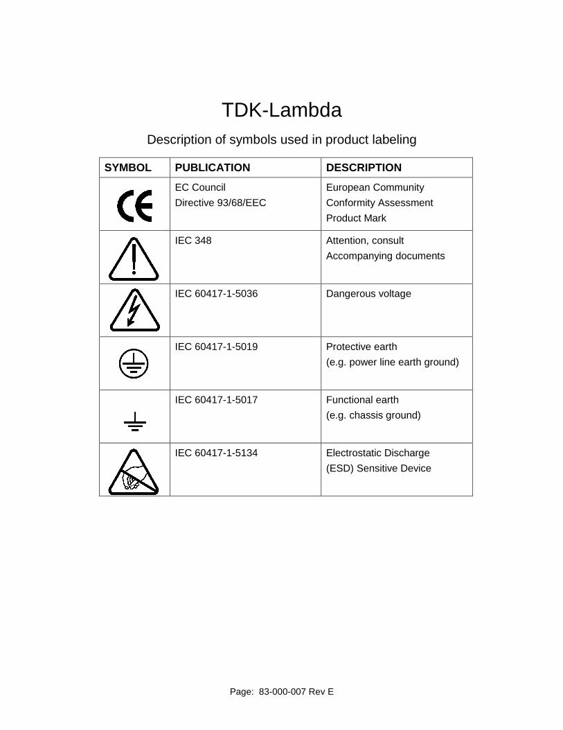
Description of symbols used in product labeling
SYMBOL PUBLICATION DESCRIPTION EC Council
Directive 93/68/EEC
European Community
Conformity Assessment
Product Mark
IEC 348 Attention, consult
Accompanying documents
IEC 60417-1-5036 Dangerous voltage
IEC 60417-1-5019 Protective earth
(e.g. power line earth ground)
IEC 60417-1-5017 Functional earth
(e.g. chassis ground)
IEC 60417-1-5134 Electrostatic Discharge
(ESD) Sensitive Device
Page: 83000011 Rev L
ELECTRICAL STANDARDS
All company primary standards are either certified or are traceable to certification by the National Institute of Standards and Technology.
CLAIM FOR DAMAGE IN SHIPMENT
This instrument received comprehensive mechanical and electrical inspection before shipment. Immediately upon receipt from the carrier, and before operation, this instrument should be inspected visually for damage caused in shipment. If such inspection reveals damage in any way, a claim should be filed with the carrier. A full report of damage should be obtained by the claim agent and this report should be forwarded to us. We will then provide a disposition of the equipment and arrange for repair or replacement.
When referring to this equipment, always include the model and serial numbers.
The “WARRANTY”, “CLAIM FOR DAMAGE IN SHIPMENT”, and “RETURNING
EQUIPMENT” information applies to equipment purchased directly from TDK-
Lambda Americas Inc. End users receiving equipment from a third party should
consult the appropriate service organization for assistance with these issues.
RETURNING EQUIPMENT
Before returning any equipment to the factory, the following steps shall be taken.
1. Notify TDK-Lambda Americas Inc. at (732) 795-4100 or follow the instructions at US.TDK-Lambda.com/HP/service.htm. Give a full description of the difficulty including the model and serial number of the unit in question. Upon receipt of this information, we will assign a Return Material Authorization (RMA) number and provide shipping instructions.
2. The customer shall prepay shipping charges. Equipment returned to us must be packed in a manner to reach us without damage. The shipping container must be marked with the RMA number in an area approximate to the shipping label with numbers that are easy to read. All returned units that do not show the RMA number on the outside of the container will be refused.
If the equipment is repaired within the warranty agreement, than TDK-Lambda Americas Inc. shall pay for the return shipping to the customer.
3. For non-warranty repairs, we will submit a cost estimate for your approval prior to proceeding. The customer shall pay return shipping charges.
MECHANICAL INSTALLATION
Most power supplies are heavy and, when rack mounted, they should be supported by rails along the sides of the supply from front to rear. The rails must adequately support the unit and not block airflow. Do not support the power supply from the front panel only.
3.2.1 TEST 1 .......................................................................................................................... 3-11 3.2.2 TEST 2 .......................................................................................................................... 3-11
3.3 CONTACTING TDK-LAMBDA AMERICAS CUSTOMER SERVICE ..................... 3-12 3.4 RETURNING DEFECTIVE UNITS ....................................................................... 3-12
4.6 CONNECTING THE HIGH VOLTAGE OUTPUT .................................................. 4-16
5. CONTROLS, INDICATORS, CONNECTORS .............................................. 5-1 5.1 FRONT PANEL LAYOUT (L Model) ....................................................................... 5-1 5.2 HV ON (Ref 1) ........................................................................................................ 5-2 5.3 OUTPUT STATUS LEDs (Ref 2) ............................................................................ 5-2
5.3.1 HV ON LED ..................................................................................................................... 5-3 5.3.2 HV OFF LED ................................................................................................................... 5-3 5.3.3 INHIBIT LED .................................................................................................................... 5-3 5.3.4 END OF CHARGE LED .................................................................................................. 5-3 5.3.5 INTERLOCK OPEN LED ................................................................................................. 5-3 5.3.6 LOAD FAULT LED .......................................................................................................... 5-3 5.3.7 OVERTEMP LED ............................................................................................................ 5-3
5.4 LOCAL VOLTAGE CONTROL (Ref 3) ................................................................... 5-3 5.5 VOLTAGE BAR GRAPH (Ref 4)............................................................................. 5-4 5.6 VOLTAGE DISPLAY (Ref 5) .................................................................................. 5-4 5.7 CURRENT DISPLAY (Ref 6) .................................................................................. 5-4 5.8 HV OFF/RESET (Ref 7) ......................................................................................... 5-4 5.9 OFF/LOCAL/REMOTE KEYSWITCH (Ref 8) ......................................................... 5-4 5.10 POWER SUPPLY STATUS LEDs (Ref 9) .............................................................. 5-4
TDK-Lambda’s ALE series 203 and 303 are state of the art switch mode high voltage power supplies, designed primarily for capacitor charging applications such as laser sys-tems, modulators, and pulse forming networks. They can also be used in many continu-ous DC applications including beam power for magnetrons, gyrotrons, klystrons and electron beam loads.
The 203L and 303L Models are fully instrumented with front panel meters displaying output voltage and current, status LEDs, a key switch for OFF, LOCAL or REMOTE op-eration, HV ON/OFF push-button switches, and a control for output voltage adjustment. The rear panel features external interlock, external inhibit, remote control and slave (parallel operation) control connections.
The 203S and 303S Models can only be operated by remote control and feature only front panel status LEDs. The "S" Models have been designed to operate as a slave unit to the "L" Models or in systems where local control is not a requirement. As many 203 or 303 supplies as required, can be connected in parallel to provide greater output power.
1.2 203 and 303 OVERVIEW
1.2.1 FEATURES
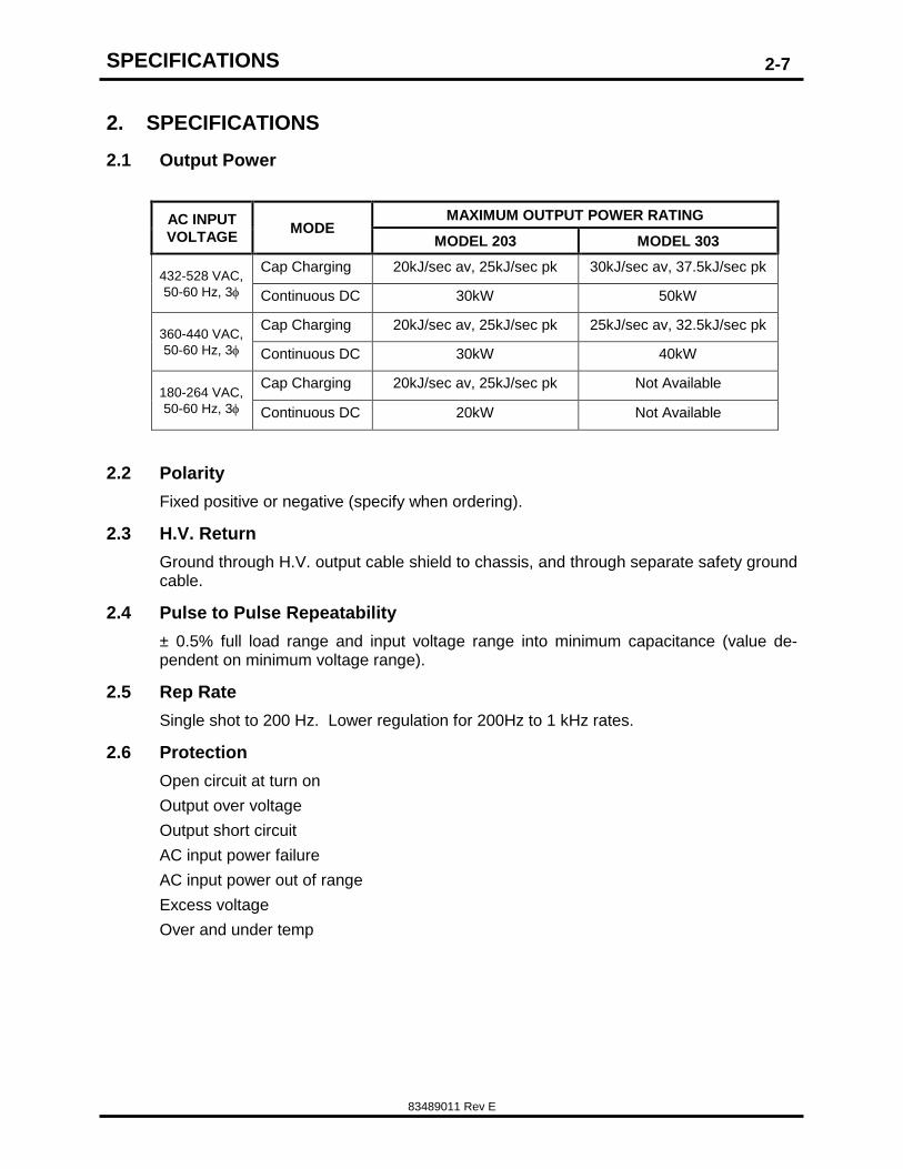
203 - 20kJ/sec capacitor charging power, 30kW in continuous DC.
303 - 30kJ/sec capacitor charging power, 50kW in continuous DC.
Output voltages from 0-1kV to 0-50kV.
Rep rates from single shot to several hundred hertz.
Local or remote operation (L Model) with comprehensive control interface.
Parallel operation (master/slave) for high power applications.
Water-cooling for major means of excess heat removal.
State of the art "Heat Pipe Cooling" system.
1.2.2 BENEFITS
Smallest package size available in this power range (50kW in 12.25” package).
Highest power available in a single package.
Low EMI/RFI.
Low ambient heating and quiet operation.
Lightweight switch mode design.
Rack mount chassis configuration.
Low stored energy provides greater safety.
Immunity to external EMI.
1.2.3 APPLICATIONS:
Charging capacitors and capacitor banks.
Powering pulse forming networks/modulators.
GENERAL INFORMATION
83489011 Rev E
1-2
Powering lasers: Excimer, flashlamp pumped dye, Yag, CO2, etc.
Line type modulators for RF generation and pulse discharge applications in re-search.
Continuous power for RF tubes – magnetron, gyrotron, TWT, klystron etc.
Electron beam applications.
DC power source for pulsed hard-tube and solid state modulators.
1.3 CAPACITOR CHARGING TECHNOLOGY
Capacitor charging applications require a power supply designed specifically for the task. The Series 203 and 303 supplies allow capacitors to be charged in pulse forming networks and modulators in a very fast, efficient and controllable manner.
The units are compact high power constant current sources that can linearly and rapidly charge a capacitive load to high voltage. Once the load capacitor is charged to the pro-grammed voltage, the supply will switch over to a voltage regulation mode and maintain the load voltage at the programmed level until the load is discharged.
The flexible design of the 203 and 303 allow the units to be ordered with (L model) or without (S model) the front panel controls and meters. The front panel controls are ideal in applications where local control and readbacks are necessary, such as R&D, labora-tory use and diagnostics. All front panel controls and indicator signals are available at the rear panel remote control connector regardless which front panel option (L or S) is selected. The S models feature only front panel status indicators and remote controls and are a cost effective solution for applications where local controls are unnecessary.
The unit is self-contained, requiring only AC power and water for cooling. Several units may be connected in parallel for higher power operation. There is no theoretical limit to the number of units that may be paralleled. Typically one master unit and one or more
slave units may be used to obtain as much output power as necessary. Consult the
factory before connecting parallel units in continuous or DC applications.
The 203 and 303 are also ideally suited to charge reservoir capacitors in resonant charging circuits where high rep rates (several kilohertz) are required, such as in metal vapor lasers or solid-state modulators.
1.4 CONTINUOUS DC OPERATION
Although the 203 and 303 series has been designed for capacitor charging applications, they can also be used as a continuous DC High Power Source for RF tubes such as klystrons, TWTs, or other DC loads such as DC-DC converters. The DC option must be specified when ordering, and the supply will be factory setup and tested with a continu-ous DC load. When 203/303 supplies are operated in continuous DC applications it is necessary to add an external capacitor between the load and ground to improve the rip-ple performance of the unit. Our online Application Note 505 describes operating capaci-tor charging supplies in DC applications, and gives guidance in determining the size of any additional external filter capacitance required.
Internal contactor and fuses for AC disconnect and protection.
Standard AC power and control connectors.
GENERAL INFORMATION
83489011 Rev E
1-3
Documentation Manual Including -
Installation
Check out
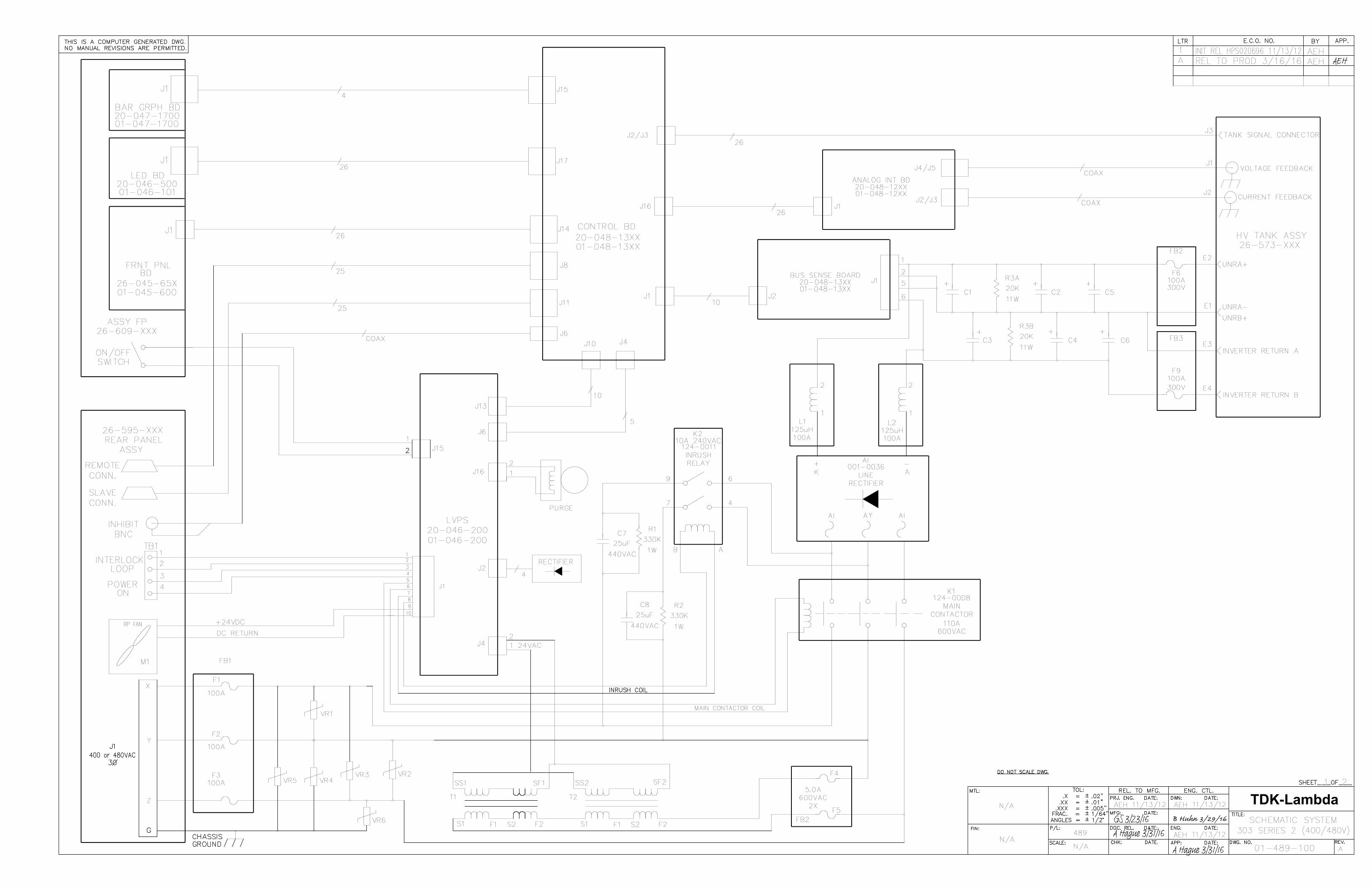
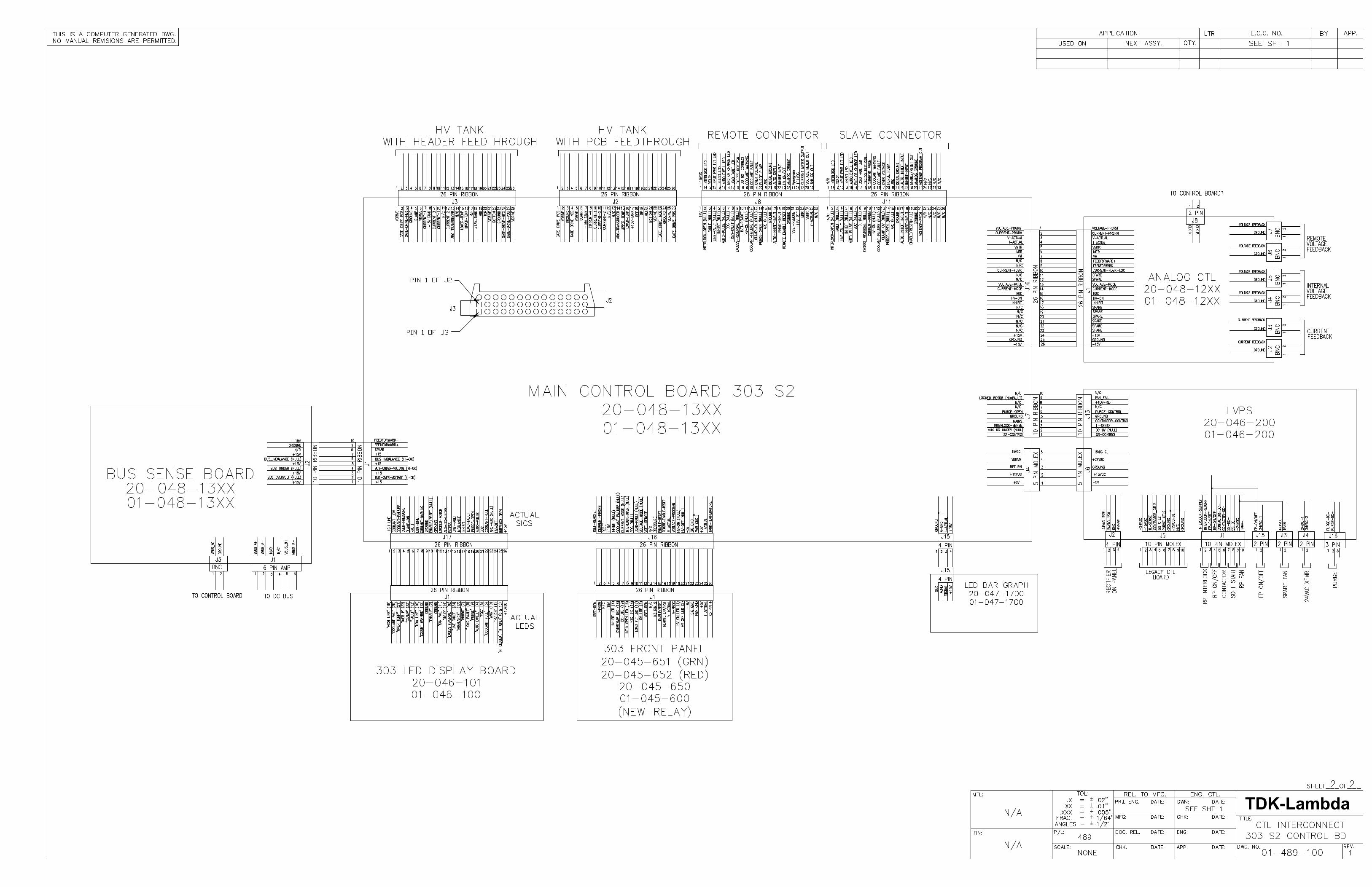
Block diagram
Suggested remote interfaces and control circuits
10 ft (3m). output cable is standard, other lengths are optional.
NOTE: This manual contains information, instructions and diagrams which apply to standard constructions. If special features or modifications have been installed, the instructions specific to that modification are contained in Addenda and take prece-dence if conflicts exist. Please take care to refer to the correct information for your unit.
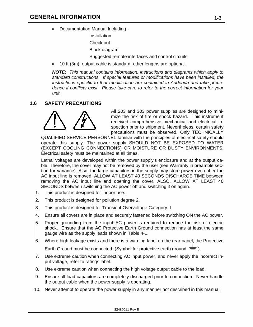
1.6 SAFETY PRECAUTIONS
All 203 and 303 power supplies are designed to mini-mize the risk of fire or shock hazard. This instrument received comprehensive mechanical and electrical in-spection prior to shipment. Nevertheless, certain safety precautions must be observed. Only TECHNICALLY
QUALIFIED SERVICE PERSONNEL familiar with the principles of electrical safety should operate this supply. The power supply SHOULD NOT BE EXPOSED TO WATER (EXCEPT COOLING CONNECTIONS) OR MOISTURE OR DUSTY ENVIRONMENTS. Electrical safety must be maintained at all times.
Lethal voltages are developed within the power supply's enclosure and at the output ca-ble. Therefore, the cover may not be removed by the user (see Warranty in preamble sec-tion for variance). Also, the large capacitors in the supply may store power even after the AC input line is removed. ALLOW AT LEAST 40 SECONDS DISCHARGE TIME between removing the AC input line and opening the cover. ALSO, ALLOW AT LEAST 40 SECONDS between switching the AC power off and switching it on again.
1. This product is designed for Indoor use.
2. This product is designed for pollution degree 2.
3. This product is designed for Transient Overvoltage Category II.
4. Ensure all covers are in place and securely fastened before switching ON the AC power.
5. Proper grounding from the input AC power is required to reduce the risk of electric shock. Ensure that the AC Protective Earth Ground connection has at least the same gauge wire as the supply leads shown in Table 4-1.
6. Where high leakage exists and there is a warning label on the rear panel, the Protective
Earth Ground must be connected. (Symbol for protective earth ground ).
7. Use extreme caution when connecting AC input power, and never apply the incorrect in-put voltage, refer to ratings label.
8. Use extreme caution when connecting the high voltage output cable to the load.
9. Ensure all load capacitors are completely discharged prior to connection. Never handle the output cable when the power supply is operating.
10. Never attempt to operate the power supply in any manner not described in this manual.
GENERAL INFORMATION
83489011 Rev E
1-4
11. Never remove DANGER and WARNING labels from the power supply. Replace lost or damaged labels immediately.
12. The power supply should only be serviced by TDK-Lambda Americas factory authorized personnel.
13. No user maintenance is required.
14. No cleaning is required.
1.7 SCOPE OF THIS MANUAL
This manual is used for installing and operating the 203 and 303 Series 2 Power Supply with a revised front panel layout shown in Figure 4-1. For older model 303 supplies refer to manual part number 83489009 which can be found on our web site. Suggestions and requirements for connecting AC power, load cables and signal cables are given. Various operating modes and programming modes are described.
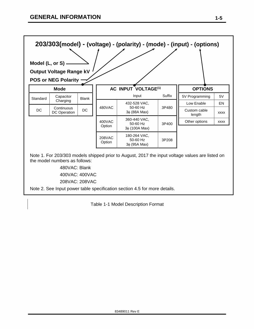
1.8 MODEL NUMBER FORMAT
The model numbering system for the 203 and 303 Series power supply includes sym-bols for features and options. They are separated by dashes.
Examples are: 303L-10KV-POS-3P400 and 203S-20KV-POS-DC-3P480.
The 203 and 303 are available with two basic front panel configurations, the L, and S. The choice of panel configuration is dependent upon the installation and system re-quirements. See section 5 for further details.
Table 1-1 shows a partial listing of the model description format for the 203/303 Power Supply family. For additional options, the customer may contact the Sales Department at TDK-Lambda Americas. Special options are typically shown as a four-digit suffix to the model number.
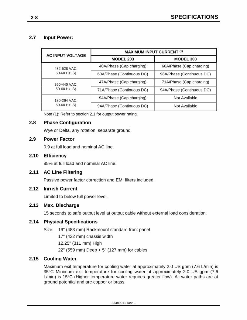
Note (1): Refer to section 2.1 for output power rating.
2.8 Phase Configuration
Wye or Delta, any rotation, separate ground.
2.9 Power Factor
0.9 at full load and nominal AC line.
2.10 Efficiency
85% at full load and nominal AC line.
2.11 AC Line Filtering
Passive power factor correction and EMI filters included.
2.12 Inrush Current
Limited to below full power level.
2.13 Max. Discharge
15 seconds to safe output level at output cable without external load consideration.
2.14 Physical Specifications
Size: 19" (483 mm) Rackmount standard front panel
17" (432 mm) chassis width
12.25" (311 mm) High
22" (559 mm) Deep + 5" (127 mm) for cables
2.15 Cooling Water
Maximum exit temperature for cooling water at approximately 2.0 US gpm (7.6 L/min) is 35°C Minimum exit temperature for cooling water at approximately 2.0 US gpm (7.6 L/min) is 15°C (Higher temperature water requires greater flow). All water paths are at ground potential and are copper or brass.
SPECIFICATIONS
83489011 Rev E
2-9
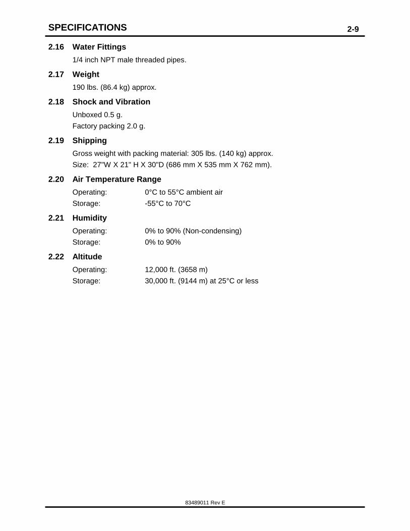
2.16 Water Fittings
1/4 inch NPT male threaded pipes.
2.17 Weight
190 lbs. (86.4 kg) approx.
2.18 Shock and Vibration
Unboxed 0.5 g.
Factory packing 2.0 g.
2.19 Shipping
Gross weight with packing material: 305 lbs. (140 kg) approx.
Size: 27"W X 21" H X 30"D (686 mm X 535 mm X 762 mm).
2.20 Air Temperature Range
Operating: 0°C to 55°C ambient air
Storage: -55°C to 70°C
2.21 Humidity
Operating: 0% to 90% (Non-condensing)
Storage: 0% to 90%
2.22 Altitude
Operating: 12,000 ft. (3658 m)
Storage: 30,000 ft. (9144 m) at 25°C or less
SPECIFICATIONS
83489011 Rev E
2-10
NOTES:
OUT-OF-BOX-INSPECTION
83489011 Rev E
3-11
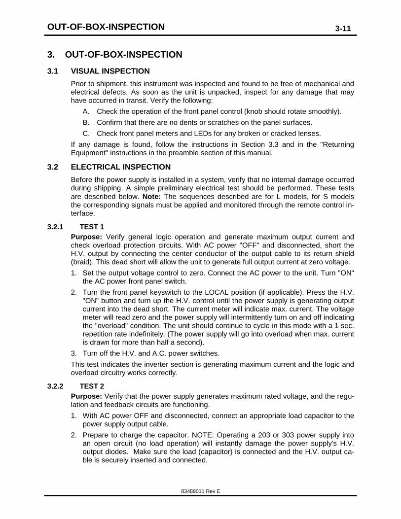
3. OUT-OF-BOX-INSPECTION
3.1 VISUAL INSPECTION
Prior to shipment, this instrument was inspected and found to be free of mechanical and electrical defects. As soon as the unit is unpacked, inspect for any damage that may have occurred in transit. Verify the following:
A. Check the operation of the front panel control (knob should rotate smoothly).
B. Confirm that there are no dents or scratches on the panel surfaces.
C. Check front panel meters and LEDs for any broken or cracked lenses.
If any damage is found, follow the instructions in Section 3.3 and in the "Returning Equipment" instructions in the preamble section of this manual.
3.2 ELECTRICAL INSPECTION
Before the power supply is installed in a system, verify that no internal damage occurred during shipping. A simple preliminary electrical test should be performed. These tests
are described below. Note: The sequences described are for L models, for S models the corresponding signals must be applied and monitored through the remote control in-terface.
3.2.1 TEST 1
Purpose: Verify general logic operation and generate maximum output current and check overload protection circuits. With AC power "OFF" and disconnected, short the H.V. output by connecting the center conductor of the output cable to its return shield (braid). This dead short will allow the unit to generate full output current at zero voltage.
1. Set the output voltage control to zero. Connect the AC power to the unit. Turn "ON" the AC power front panel switch.
2. Turn the front panel keyswitch to the LOCAL position (if applicable). Press the H.V. "ON" button and turn up the H.V. control until the power supply is generating output current into the dead short. The current meter will indicate max. current. The voltage meter will read zero and the power supply will intermittently turn on and off indicating the "overload" condition. The unit should continue to cycle in this mode with a 1 sec. repetition rate indefinitely. (The power supply will go into overload when max. current is drawn for more than half a second).
3. Turn off the H.V. and A.C. power switches.
This test indicates the inverter section is generating maximum current and the logic and overload circuitry works correctly.
3.2.2 TEST 2
Purpose: Verify that the power supply generates maximum rated voltage, and the regu-lation and feedback circuits are functioning.
1. With AC power OFF and disconnected, connect an appropriate load capacitor to the power supply output cable.
2. Prepare to charge the capacitor. NOTE: Operating a 203 or 303 power supply into an open circuit (no load operation) will instantly damage the power supply's H.V. output diodes. Make sure the load (capacitor) is connected and the H.V. output ca-ble is securely inserted and connected.
OUT-OF-BOX-INSPECTION
83489011 Rev E
3-12
3. For L models turn the voltage control on the front panel turned all the way down to zero (counter clockwise), apply AC power and press the HV ON button. By turning up the H.V. control knob the capacitor will charge to the voltage indicated on the front panel voltmeter. The power supply may be turned all the way up to its max. output voltage provided the load capacitor is sufficiently rated.
4. By turning the voltage control down or depressing the H.V. OFF button, the capacitor will "bleed" down through the internal voltage divider resistors used for regulation feedback.
Test #2 indicates the H.V. section is working correctly. Tests 1 and 2 generally indicate the unit is functioning as designed. Although 100% power had not been generated, these two tests give greater than 90% confidence that the unit is not damaged.
If any inconsistency from the above test procedure is noted, do not hesitate to call TDK-Lambda Americas Customer Service for assistance.
The supply and the coolant filled HV assembly should not be opened unless advised by TDK-Lambda Americas personnel. The coolant filled HV tank has been cleaned and the hermetically sealed at the factory, opening the supply or the assembly will void the facto-ry warranty, and may compromise performance.
3.3 CONTACTING TDK-LAMBDA AMERICAS CUSTOMER SERVICE
When contacting customer service locate the product description, part number and seri-al number from the label located on the rear of the unit, and have this information avail-able.
Customer Service, or an approved Service Center, should be contacted if:
The power supply is mechanically or electrically damaged.
The power supply requires on-site calibration, or replacement warning decals.
The customer has questions about a special application that is not described in this manual.
Normally, the customer may NOT open any chassis covers that have a warranty seal. Breaking a seal will void the warranty.
At the discretion of TDK-Lambda Americas, the customer may be granted permission to break the warranty seal and open the chassis covers. Customer Service shall confirm the permission by sending a replacement seal. Once the unit has been serviced, the customer shall close the cover and apply the replacement seal adjacent to (not on top of) the broken seal.
3.4 RETURNING DEFECTIVE UNITS
The procedure for returning defective products is given in section 3.3 of this manual.
INSTALLATION
83489011 Rev E
4-13
4. INSTALLATION
4.1 19-INCH RACK MOUNTING
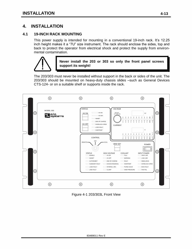
This power supply is intended for mounting in a conventional 19-inch rack. It’s 12.25 inch height makes it a “7U” size instrument. The rack should enclose the sides, top and back to protect the operator from electrical shock and protect the supply from environ-mental contamination.
Never install the 203 or 303 so only the front panel screws
support its weight!
The 203/303 must never be installed without support in the back or sides of the unit. The 203/303 should be mounted on heavy-duty chassis slides –such as General Devices CTS-124- or on a suitable shelf or supports inside the rack.
STATUS COOLANT INPUT POWERHIGH VOLTAGE
ENABLE
INHIBIT
AUTOINHIBIT
SUMMARY FAULT
INTERNAL ARCLOAD FAULT
LINE FAULT
HV ON
HV OFF
END OF CHARGE
EXCESS REVERSAL
CLAMP
FULL
WARNING
FAULT
OVERTEMP
PURGE VALVE
OVER PRESSURE
HIGH LINE
LOW LINE
IMBALANCE
INTERLOCK OPEN
BIAS FAULT
FAN FAIL
POWER
STATUS
HV ON
CONTROL
ADJUST
OVERTEMP
LOAD FAULT
END OF CHARGE
INHIBIT
HV OFF
VIEW SET
HV OFF
HV ON
INTERLOCK OPEN
LOCALREMOTEOFF
110
%
10080 90706050403020100
110
%
10080 90706050403020100
10 TURN INC
CURRENT
VOLTAGE
kV
A
MODEL 303
Figure 4-1 203/303L Front View
INSTALLATION
83489011 Rev E
4-14
INH
IBIT
RE
MO
TE
COOLANT
HV OUTPUT
TB 1 AC INPUT
INTERLOCK/POWER ON
TB2 1 2 3 4
A B C N GND
1 2 3 4 5
COOLANT WATERIN OUT
SL
AV
E
inHg psi
kPa
-30
-100
-50
150
50
0
200
100
-20
-10
010
20
30
!438-528 VAC
50/60 Hz
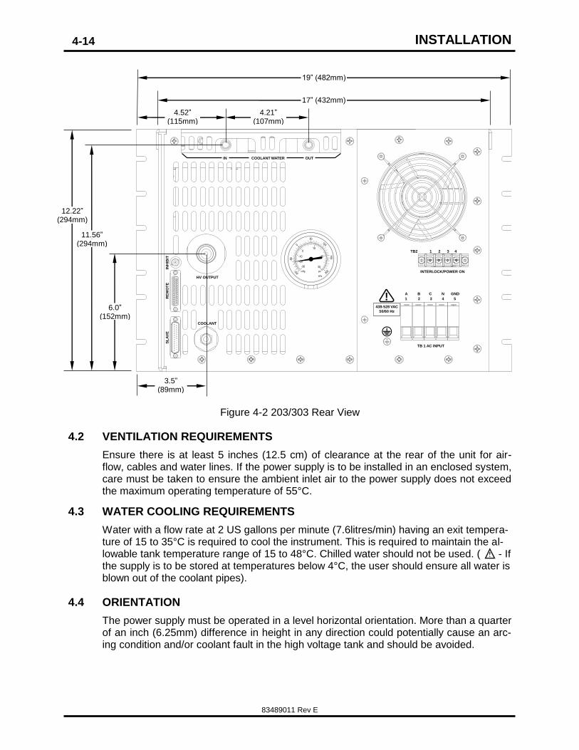
Figure 4-2 203/303 Rear View
4.2 VENTILATION REQUIREMENTS
Ensure there is at least 5 inches (12.5 cm) of clearance at the rear of the unit for air-flow, cables and water lines. If the power supply is to be installed in an enclosed system, care must be taken to ensure the ambient inlet air to the power supply does not exceed the maximum operating temperature of 55°C.
4.3 WATER COOLING REQUIREMENTS
Water with a flow rate at 2 US gallons per minute (7.6litres/min) having an exit tempera-ture of 15 to 35°C is required to cool the instrument. This is required to maintain the al-lowable tank temperature range of 15 to 48°C. Chilled water should not be used. ( - If the supply is to be stored at temperatures below 4°C, the user should ensure all water is blown out of the coolant pipes).
4.4 ORIENTATION
The power supply must be operated in a level horizontal orientation. More than a quarter of an inch (6.25mm) difference in height in any direction could potentially cause an arc-ing condition and/or coolant fault in the high voltage tank and should be avoided.
19” (482mm)
17” (432mm)
4.52” (115mm)
4.21” (107mm)
3.5” (89mm)
6.0” (152mm)
11.56” (294mm)
12.22” (294mm)
INSTALLATION
83489011 Rev E
4-15
4.5 AC POWER CONNECTION
The maximum voltage allowed between any two AC input
terminals is 550VAC. If this voltage is exceeded,
catastrophic damage will result, that is not covered by
TDK-Lambda Americas standard warranty.
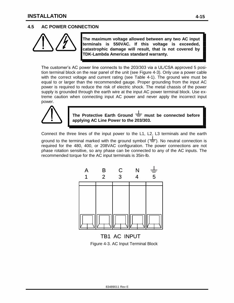
The customer’s AC power line connects to the 203/303 via a UL/CSA approved 5 posi-tion terminal block on the rear panel of the unit (see Figure 4-3). Only use a power cable with the correct voltage and current rating (see Table 4-1). The ground wire must be equal to or larger than the recommended gauge. Proper grounding from the input AC power is required to reduce the risk of electric shock. The metal chassis of the power supply is grounded through the earth wire at the input AC power terminal block. Use ex-treme caution when connecting input AC power and never apply the incorrect input power.
The Protective Earth Ground must be connected before
applying AC Line Power to the 203/303.
Connect the three lines of the input power to the L1, L2, L3 terminals and the earth
ground to the terminal marked with the ground symbol ( ). No neutral connection is required for the 480, 400, or 208VAC configuration. The power connections are not phase rotation sensitive, so any phase can be connected to any of the AC inputs. The recommended torque for the AC input terminals is 35in-lb.
Figure 4-3. AC Input Terminal Block
L
1
A
1
B
2
C
3
N
4 5
TB1 AC INPUT
A
1
B
2
C
3
N
4 5
TB1 AC INPUT
INSTALLATION
83489011 Rev E
4-16
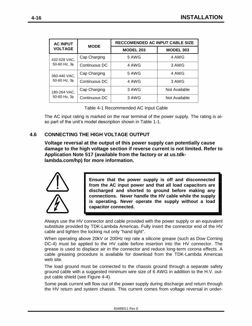
AC INPUT
VOLTAGE MODE
RECCOMENDED AC INPUT CABLE SIZE
MODEL 203 MODEL 303
432-528 VAC,
50-60 Hz, 3
Cap Charging 5 AWG 4 AWG
Continuous DC 4 AWG 3 AWG
360-440 VAC,
50-60 Hz, 3
Cap Charging 5 AWG 4 AWG
Continuous DC 4 AWG 3 AWG
180-264 VAC,
50-60 Hz, 3
Cap Charging 3 AWG Not Available
Continuous DC 3 AWG Not Available
Table 4-1 Recommended AC Input Cable
The AC input rating is marked on the rear terminal of the power supply. The rating is al-so part of the unit’s model description shown in Table 1-1.
4.6 CONNECTING THE HIGH VOLTAGE OUTPUT
Voltage reversal at the output of this power supply can potentially cause
damage to the high voltage section if reverse current is not limited. Refer to
Application Note 517 (available from the factory or at us.tdk-
lambda.com/hp) for more information.
Ensure that the power supply is off and disconnected
from the AC input power and that all load capacitors are
discharged and shorted to ground before making any
connections. Never handle the HV cable while the supply
is operating. Never operate the supply without a load
capacitor connected.
Always use the HV connector and cable provided with the power supply or an equivalent substitute provided by TDK-Lambda Americas. Fully insert the connector end of the HV cable and tighten the locking nut only "hand tight".
When operating above 20kV or 200Hz rep rate a silicone grease (such as Dow Corning DC-4) must be applied to the HV cable before insertion into the HV connector. The grease is used to displace air in the connector and reduce long-term corona effects. A cable greasing procedure is available for download from the TDK-Lambda Americas web site.
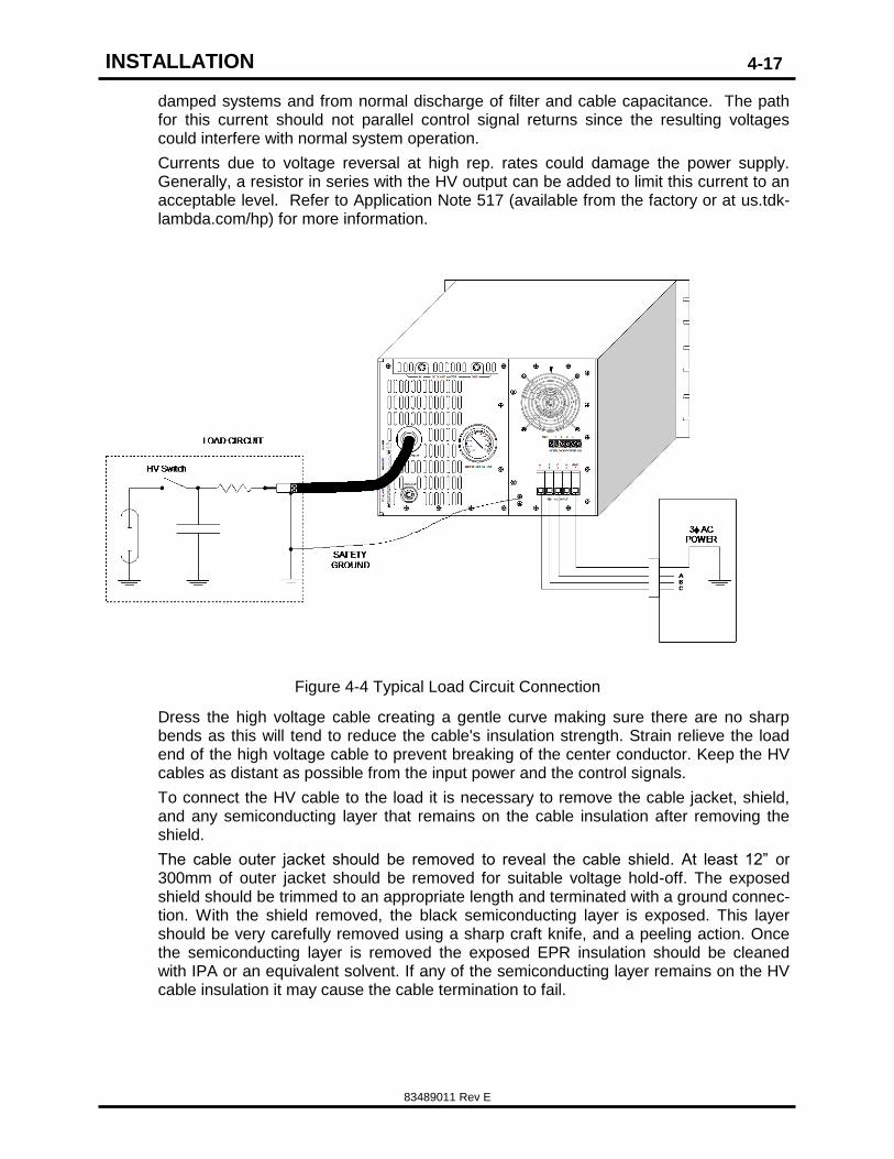
The load ground must be connected to the chassis ground through a separate safety ground cable with a suggested minimum wire size of 6 AWG in addition to the H.V. out-put cable shield (see Figure 4-4).
Some peak current will flow out of the power supply during discharge and return through the HV return and system chassis. This current comes from voltage reversal in under-
INSTALLATION
83489011 Rev E
4-17
damped systems and from normal discharge of filter and cable capacitance. The path for this current should not parallel control signal returns since the resulting voltages could interfere with normal system operation.
Currents due to voltage reversal at high rep. rates could damage the power supply. Generally, a resistor in series with the HV output can be added to limit this current to an acceptable level. Refer to Application Note 517 (available from the factory or at us.tdk-lambda.com/hp) for more information.
Figure 4-4 Typical Load Circuit Connection
Dress the high voltage cable creating a gentle curve making sure there are no sharp bends as this will tend to reduce the cable's insulation strength. Strain relieve the load end of the high voltage cable to prevent breaking of the center conductor. Keep the HV cables as distant as possible from the input power and the control signals.
To connect the HV cable to the load it is necessary to remove the cable jacket, shield, and any semiconducting layer that remains on the cable insulation after removing the shield.
The cable outer jacket should be removed to reveal the cable shield. At least 12” or 300mm of outer jacket should be removed for suitable voltage hold-off. The exposed shield should be trimmed to an appropriate length and terminated with a ground connec-tion. With the shield removed, the black semiconducting layer is exposed. This layer should be very carefully removed using a sharp craft knife, and a peeling action. Once the semiconducting layer is removed the exposed EPR insulation should be cleaned with IPA or an equivalent solvent. If any of the semiconducting layer remains on the HV cable insulation it may cause the cable termination to fail.
INSTALLATION
83489011 Rev E
4-18
NOTES:
CONTROLS, INDICATORS, CONNECTORS
83489011 Rev E
5-1
5. CONTROLS, INDICATORS, CONNECTORS
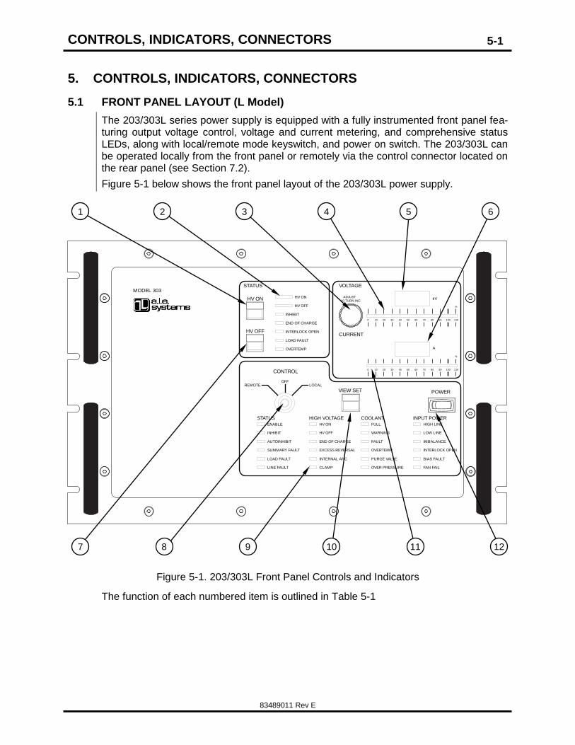
5.1 FRONT PANEL LAYOUT (L Model)
The 203/303L series power supply is equipped with a fully instrumented front panel fea-turing output voltage control, voltage and current metering, and comprehensive status LEDs, along with local/remote mode keyswitch, and power on switch. The 203/303L can be operated locally from the front panel or remotely via the control connector located on the rear panel (see Section 7.2).
Figure 5-1 below shows the front panel layout of the 203/303L power supply.
STATUS COOLANT INPUT POWERHIGH VOLTAGE
ENABLE
INHIBIT
AUTOINHIBIT
SUMMARY FAULT
INTERNAL ARCLOAD FAULT
LINE FAULT
HV ON
HV OFF
END OF CHARGE
EXCESS REVERSAL
CLAMP
FULL
WARNING
FAULT
OVERTEMP
PURGE VALVE
OVER PRESSURE
HIGH LINE
LOW LINE
IMBALANCE
INTERLOCK OPEN
BIAS FAULT
FAN FAIL
POWER
STATUS
HV ON
CONTROL
ADJUST
OVERTEMP
LOAD FAULT
END OF CHARGE
INHIBIT
HV OFF
VIEW SET
HV OFF
HV ON
INTERLOCK OPEN
LOCALREMOTEOFF
110
%
10080 90706050403020100
110
%
10080 90706050403020100
10 TURN INC
CURRENT
VOLTAGE
kV
A
MODEL 303
Figure 5-1. 203/303L Front Panel Controls and Indicators
The function of each numbered item is outlined in Table 5-1
7 8 9 10 12 11
1 2 3 4 5 6
CONTROLS, INDICATORS, CONNECTORS
83489011 Rev E
5-2
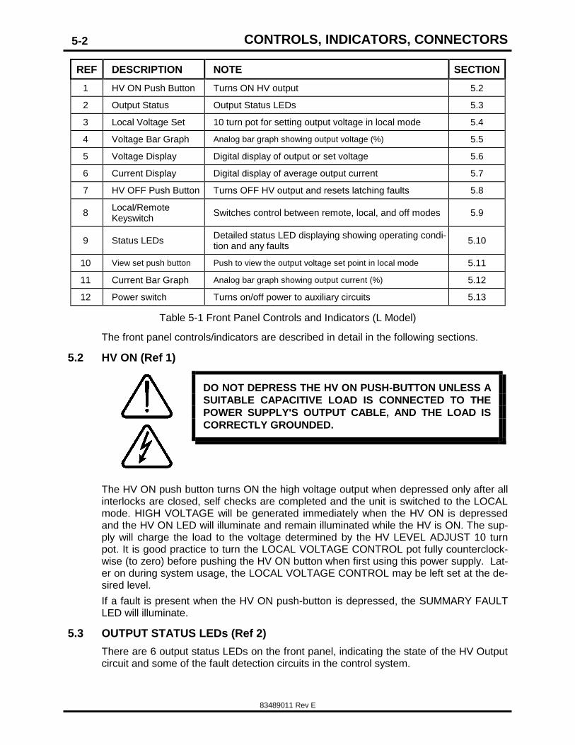
REF DESCRIPTION NOTE SECTION
1 HV ON Push Button Turns ON HV output 5.2
2 Output Status Output Status LEDs 5.3
3 Local Voltage Set 10 turn pot for setting output voltage in local mode 5.4
4 Voltage Bar Graph Analog bar graph showing output voltage (%) 5.5
5 Voltage Display Digital display of output or set voltage 5.6
6 Current Display Digital display of average output current 5.7
7 HV OFF Push Button Turns OFF HV output and resets latching faults 5.8
8 Local/Remote Keyswitch
Switches control between remote, local, and off modes 5.9
9 Status LEDs Detailed status LED displaying showing operating condi-tion and any faults
5.10
10 View set push button Push to view the output voltage set point in local mode 5.11
11 Current Bar Graph Analog bar graph showing output current (%) 5.12
12 Power switch Turns on/off power to auxiliary circuits 5.13
Table 5-1 Front Panel Controls and Indicators (L Model)
The front panel controls/indicators are described in detail in the following sections.
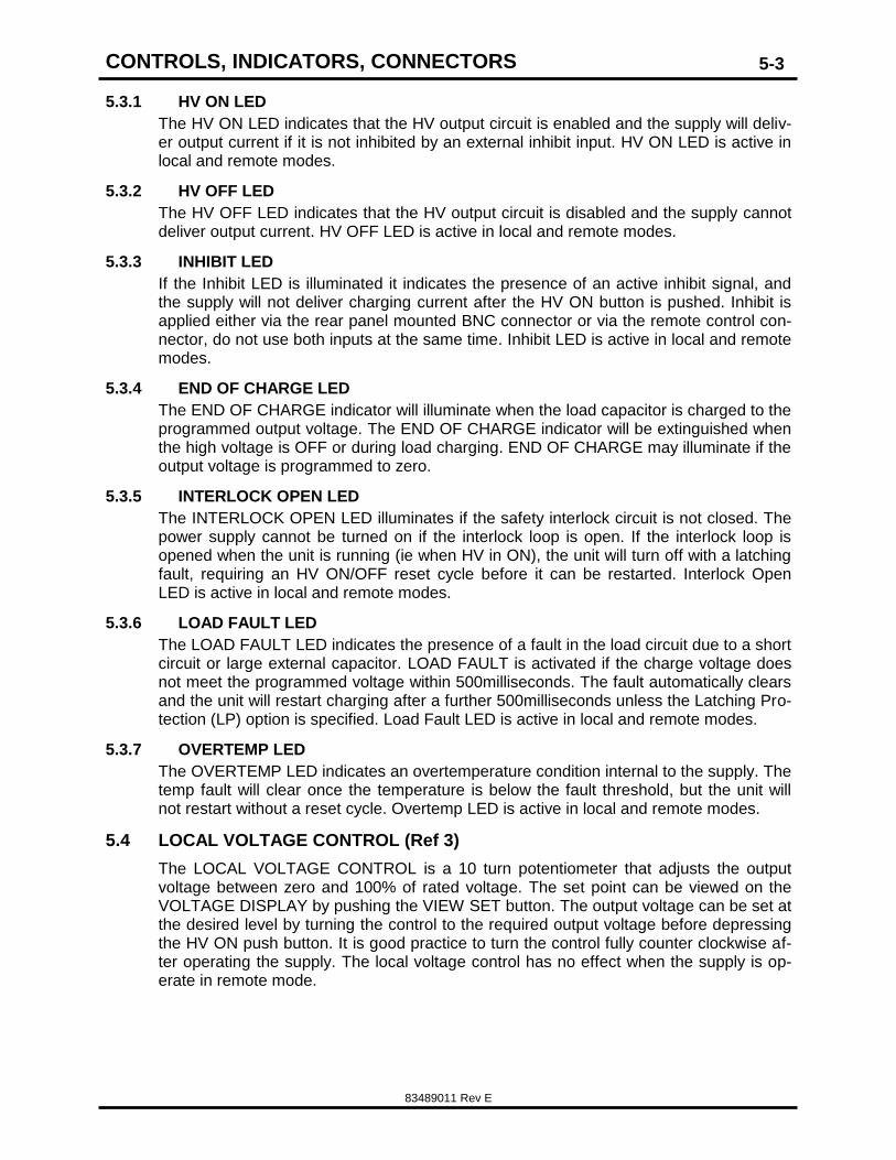
5.2 HV ON (Ref 1)
DO NOT DEPRESS THE HV ON PUSH-BUTTON UNLESS A
SUITABLE CAPACITIVE LOAD IS CONNECTED TO THE
POWER SUPPLY'S OUTPUT CABLE, AND THE LOAD IS
CORRECTLY GROUNDED.
The HV ON push button turns ON the high voltage output when depressed only after all interlocks are closed, self checks are completed and the unit is switched to the LOCAL mode. HIGH VOLTAGE will be generated immediately when the HV ON is depressed and the HV ON LED will illuminate and remain illuminated while the HV is ON. The sup-ply will charge the load to the voltage determined by the HV LEVEL ADJUST 10 turn pot. It is good practice to turn the LOCAL VOLTAGE CONTROL pot fully counterclock-wise (to zero) before pushing the HV ON button when first using this power supply. Lat-er on during system usage, the LOCAL VOLTAGE CONTROL may be left set at the de-sired level.
If a fault is present when the HV ON push-button is depressed, the SUMMARY FAULT LED will illuminate.
5.3 OUTPUT STATUS LEDs (Ref 2)
There are 6 output status LEDs on the front panel, indicating the state of the HV Output circuit and some of the fault detection circuits in the control system.
CONTROLS, INDICATORS, CONNECTORS
83489011 Rev E
5-3
5.3.1 HV ON LED
The HV ON LED indicates that the HV output circuit is enabled and the supply will deliv-er output current if it is not inhibited by an external inhibit input. HV ON LED is active in local and remote modes.
5.3.2 HV OFF LED
The HV OFF LED indicates that the HV output circuit is disabled and the supply cannot deliver output current. HV OFF LED is active in local and remote modes.
5.3.3 INHIBIT LED
If the Inhibit LED is illuminated it indicates the presence of an active inhibit signal, and the supply will not deliver charging current after the HV ON button is pushed. Inhibit is applied either via the rear panel mounted BNC connector or via the remote control con-nector, do not use both inputs at the same time. Inhibit LED is active in local and remote modes.
5.3.4 END OF CHARGE LED
The END OF CHARGE indicator will illuminate when the load capacitor is charged to the programmed output voltage. The END OF CHARGE indicator will be extinguished when the high voltage is OFF or during load charging. END OF CHARGE may illuminate if the output voltage is programmed to zero.
5.3.5 INTERLOCK OPEN LED
The INTERLOCK OPEN LED illuminates if the safety interlock circuit is not closed. The power supply cannot be turned on if the interlock loop is open. If the interlock loop is opened when the unit is running (ie when HV in ON), the unit will turn off with a latching fault, requiring an HV ON/OFF reset cycle before it can be restarted. Interlock Open LED is active in local and remote modes.
5.3.6 LOAD FAULT LED
The LOAD FAULT LED indicates the presence of a fault in the load circuit due to a short circuit or large external capacitor. LOAD FAULT is activated if the charge voltage does not meet the programmed voltage within 500milliseconds. The fault automatically clears and the unit will restart charging after a further 500milliseconds unless the Latching Pro-tection (LP) option is specified. Load Fault LED is active in local and remote modes.
5.3.7 OVERTEMP LED
The OVERTEMP LED indicates an overtemperature condition internal to the supply. The temp fault will clear once the temperature is below the fault threshold, but the unit will not restart without a reset cycle. Overtemp LED is active in local and remote modes.
5.4 LOCAL VOLTAGE CONTROL (Ref 3)
The LOCAL VOLTAGE CONTROL is a 10 turn potentiometer that adjusts the output voltage between zero and 100% of rated voltage. The set point can be viewed on the VOLTAGE DISPLAY by pushing the VIEW SET button. The output voltage can be set at the desired level by turning the control to the required output voltage before depressing the HV ON push button. It is good practice to turn the control fully counter clockwise af-ter operating the supply. The local voltage control has no effect when the supply is op-erate in remote mode.
CONTROLS, INDICATORS, CONNECTORS
83489011 Rev E
5-4
5.5 VOLTAGE BAR GRAPH (Ref 4)
The voltage bar graph is a 'quick view' analog percentage indication of the voltage measured at the power supply output. Bar graph is active in local and remote modes.
5.6 VOLTAGE DISPLAY (Ref 5)
The Voltage Display is a 4 digit LED indicator showing the voltage measured at the power supply output. This display momentarily shows the output program voltage after the View Set button is depressed. Voltage Display is active in local and remote modes.
5.7 CURRENT DISPLAY (Ref 6)
The Current Display is a 4 digit LED indicator showing the average current delivered by the power supply output. Current display is active in local and remote modes.
5.8 HV OFF/RESET (Ref 7)
The HV OFF push button is a momentary switch that when depressed turns off HV out-put. If the power supply shuts off with a summary fault (indicated by SUMMART FAULT LED illuminating), then this condition can be reset by pushing the HV OFF button. If the supply is operated in remote mode the HV OFF push button will still function.
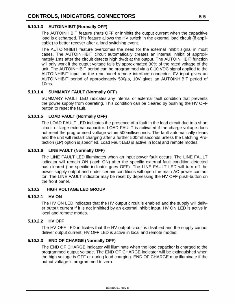
5.9 OFF/LOCAL/REMOTE KEYSWITCH (Ref 8)
DO NOT MOVE THE KEYSWITCH POSITION FROM OFF TO LOCAL OR REMOTE UNLESS A SUITABLE CAPACITIVE
LOAD IS CONNECTED TO THE POWER SUPPLY'S OUTPUT CABLE, AND THE LOAD IS CORRECTLY GROUNDED.
The OFF/LOCA/REMOTE Keyswitch switches the power supply operating modes be-tween OFF, LOCAL, and REMOTE. The key can be removed in the OFF position to prevent unauthorized use. If the switch is in the LOCAL position the supply will operate from the front panel. In the REMOTE position the supply can only be operated via the remote control interface. An L model supply can simulate an S model with the key in the REMOTE position.
5.10 POWER SUPPLY STATUS LEDs (Ref 9)
There are four distinct sets of status LEDs on the 203/303L/S front panel. Each group indicates the status of a specific section of the power supply.
5.10.1 STATUS LED GROUP
5.10.1.1 ENABLE
Indicates the HV output circuitry is Enabled and HV may be present at the power supply output.
5.10.1.2 INHIBIT
The INHIBIT indicator displays the logical OR of all the internal and external signals that prevent HV output current, including EOC, AUTOINHIBIT, EXTERNAL INHIBIT, OVERLOAD, and any fault. If the INHIBIT indicator is OFF and the unit is not delivering charge current, there is an internal power supply failure that may require servicing by authorized service personnel. If an inhibit signal (HIGH) is applied at the rear panel BNC connector, the INHIBIT indicator will illuminate and output current cannot be delivered.
CONTROLS, INDICATORS, CONNECTORS
83489011 Rev E
5-5
5.10.1.3 AUTOINHIBIT (Normally OFF)
The AUTOINHIBIT feature shuts OFF or inhibits the output current when the capacitive load is discharged. This feature allows the HV switch in the external load circuit (if appli-cable) to better recover after a load switching event.
The AUTOINHIBIT feature overcomes the need for the external inhibit signal in most cases. The AUTOINHIBIT circuit automatically creates an internal inhibit of approxi-mately 1ms after the circuit detects high dv/dt at the output. The AUTOINHIBIT function will only work if the output voltage falls by approximated 30% of the rated voltage of the unit. The AUTOINHIBIT period can be programmed via a 0-10 VDC signal applied to the AUTOINHIBIT input on the rear panel remote interface connector. 0V input gives an
AUTOINHIBIT period of approximately 500s, 10V gives an AUTOINHIBIT period of 10ms.
5.10.1.4 SUMMARY FAULT (Normally OFF)
SUMMARY FAULT LED indicates any internal or external fault condition that prevents the power supply from operating. This condition can be cleared by pushing the HV OFF button to reset the fault.
5.10.1.5 LOAD FAULT (Normally OFF)
The LOAD FAULT LED indicates the presence of a fault in the load circuit due to a short circuit or large external capacitor. LOAD FAULT is activated if the charge voltage does not meet the programmed voltage within 500milliseconds. The fault automatically clears and the unit will restart charging after a further 500milliseconds unless the Latching Pro-tection (LP) option is specified. Load Fault LED is active in local and remote modes.
5.10.1.6 LINE FAULT (Normally OFF)
The LINE FAULT LED illuminates when an input power fault occurs. The LINE FAULT indicator will remain ON (latch ON) after the specific external fault condition detected has cleared (the specific indicator goes OFF). The LINE FAULT LED will turn off the power supply output and under certain conditions will open the main AC power contac-tor. The LINE FAULT indicator may be reset by depressing the HV OFF push-button on the front panel.
5.10.2 HIGH VOLTAGE LED GROUP
5.10.2.1 HV ON
The HV ON LED indicates that the HV output circuit is enabled and the supply will deliv-er output current if it is not inhibited by an external inhibit input. HV ON LED is active in local and remote modes.
5.10.2.2 HV OFF
The HV OFF LED indicates that the HV output circuit is disabled and the supply cannot deliver output current. HV OFF LED is active in local and remote modes.
5.10.2.3 END OF CHARGE (Normally OFF)
The END OF CHARGE indicator will illuminate when the load capacitor is charged to the programmed output voltage. The END OF CHARGE indicator will be extinguished when the high voltage is OFF or during load charging. END OF CHARGE may illuminate if the output voltage is programmed to zero.
CONTROLS, INDICATORS, CONNECTORS
83489011 Rev E
5-6
5.10.2.4 EXCESS REVERSAL (Normally OFF)
This indicator will illuminate if excess voltage reversal is detected at the HV output. A large reversal would cause damage to the power supply by drawing too much current through the output diode rectifiers. While the EXCESS REVERSAL sense circuit does not directly protect the diodes, it will stop the power supply from continuing to run in the case where reversal may be building up and could cause damage if left unchecked.
This protection circuit will reset automatically after three (3) seconds and restart the power supply. Repeated operation of this circuit indicates the presence of a persistent problem that must be corrected by some form of protection, clipper circuit or series re-sistor. Refer to Application Note 517 (available from the factory or at us.tdk-lambda.com/hp) for more information.
5.10.2.5 INTERNAL ARC (Normally OFF)
When illuminated, the INTERNAL ARC indicator signals a major fault internal to the high voltage tank of the power supply. This type of fault may be reset if the POWER is cy-cled; however, if it recurs, the unit should not be used any further because the output may be uncontrolled if present and could cause further damage to the supply or its load. The power supply should then be serviced by qualified personnel.
5.10.2.6 CLAMP (Normally OFF)
The CLAMP indicator illuminates when an overvoltage condition is detected on the out-put. The CLAMP indicator will also illuminate if the unit is being programmed to a higher voltage than it is rated for. The power supply will turn OFF the high voltage output (inhib-ited) and may be reset by depressing the HV OFF push-button on the front panel when the overvoltage condition is no longer present.
5.10.3 COOLANT LED GROUP
In the event of any coolant faults the user should verify installation orientation is in ac-cordance with Section 4.4 prior to contacting TDK-Lambda Americas.
5.10.3.1 FULL (Normally ON)
When illuminated, this indicator signals that the high voltage tank in filled to the correct level with coolant. This indicator may be extinguished if the unit is cold.
5.10.3.2 WARNING (Normally OFF)
This indicator will FLASH if the coolant drops below its safe operation level, indicating that the coolant may be leaking (there are no environmental or safety hazards from this coolant leaking. It will evaporate before it collects). The unit should be serviced if the coolant is low.
5.10.4 FAULT (Normally OFF)
The FAULT indicator when illuminated indicates the coolant level is below the allowable level to safely operate the power supply. The FAULT indicator will turn OFF the high voltage output and it cannot be reset until the coolant level is corrected. The unit must be serviced by authorized service personnel.
5.10.4.1 OVERTEMP (Normally OFF)
The OVER TEMP LED Illuminates if the HV tank temperature is outside of its operating limits. The fixed operating limits have minimum low temperature and a maximum high temperature. When illuminated, the TEMP indicator will turn OFF the high voltage out-
CONTROLS, INDICATORS, CONNECTORS
83489011 Rev E
5-7
put. When the internal temperature returns to a normal level, the output may be switched back on.
The Cooling fluid has a wide operating temperature range and is controlled and stabi-lized by the cooling water flowing through the high voltage tank. The maximum allowable tank temperature is 70°C, and the minimum is 15°C.
This temperature range can be maintained by running normal tap water through the power module at a rate of 2 gallons per minute (7.58 L/min). Chilled water should not be used, it can cause the lower operating temperature limit to be reached, as well as caus-ing condensation to form which should always be avoided. Condensation in the power module could cause damage and the warranty will be void.
5.10.4.2 PURGE VALVE (Normally OFF)
The PURGE indicator illuminates when the purge valve opens. The STP vapor pressure of the coolant used in the High Voltage tank is below atmospheric pressure, hence a small leak in this enclosure will cause outside air to leak in. The coolant vapor is much heavier than air so this remains at the top of the tank. The effect of this air is to increase the temperature of the top of the liquid relative to the bottom. This temperature differ-ence is sensed by the power supply control circuits and if out of range a valve is opened to allow purging of the air from the top of the sealed assembly. There is a check value in line with this value so flow will only occur when the HV tank internal pressure is above prevailing atmospheric pressure. Purging will continue until the correct temperature dif-ference is established and then the valve closes. To cause the internal pressure to be above atmospheric the supply must be running hot enough to raise the internal pressure above atmospheric which at the recommended flows and temperatures may require re-ducing or temporarily stopping the water flow. It may take several purge cycles for this condition to fully correct itself.
5.10.4.3 OVER PRESSURE (Normally OFF)
It indicates the presence of an OVER PRESSURE condition in the HV tank. Can be re-set by depressing the HV OFF button, after the condition has cleared. Repeated OVER PRESSURE faults are an indication of a problem in the HV tank. Contact the factory for service.
5.10.5 INPUT POWER LED GROUP (External Faults)
5.10.5.1 HIGH LINE (Normally OFF)
The HIGH LINE LED illuminates when the external AC input voltage is above the maxi-mum limit (typically 10% above nominal). Damage can result if the AC input exceeds the rating and so the supply disconnects itself from the line by opening the contactor.
When the HIGH LINE condition is removed the indicator extinguishes and the power supply can be reset by operating the HV OFF push-button.
5.10.5.2 LOW LINE (Normally OFF)
The LOW LINE LED will illuminate if the AC input voltage drops below approximately 85% of the nominal nameplate level. The power supply will continue to deliver output current unless the AC input voltage dip is too great (either low voltage or for a long time). The power supply will shut down the output until the AC line is restored. The line fault resets the power supply automatically.
CONTROLS, INDICATORS, CONNECTORS
83489011 Rev E
5-8
5.10.5.3 IMBALANCE (Normally OFF)
The IMBALANCE LED illuminates if an internal power imbalance occurs, which could happen under abnormal power conditions. The fault will automatically reset when the condition corrects itself.
The AC contactor is opened and the FAULT indicator is illuminated which may be reset using the push-button after the IMBALANCE LED extinguishes. This does not indicate an AC line to line imbalance.
5.10.5.4 INTERLOCK OPEN (Normally OFF)
INTERLOCK OPEN illuminates when the interlock loop on rear panel is opened. If the interlock is opened while the supply is operating, the main AC line contactor will be opened, disconnecting AC power from the HV circuitry. The INTERLOCK OPEN LED indication is reset automatically when the interlock circuit is closed (LED extinguished), but before power can be generated the fault condition must be reset by pushing the HV OFF push-button.
5.10.5.5 BIAS FAULT (Normally OFF)
When illuminated indicates the internal DC control voltage is low, or out of range.
5.10.5.6 FAN FAIL (Normally OFF)
Indicates failure of the auxiliary cooling fan. The power supply should be removed for service if this indicator is illuminated.
5.11 VIEW SET push button (Ref 10)
The view set push button changes the reading on the digital voltage display from the power supply output voltage, to the programmed voltage set on the local voltage set po-tentiometer. After pushing this button the set voltage is displayed for approximately 3 seconds.
5.12 CURRENT BAR GRAPH (Ref 11)
The current bar graph is a 'quick view' analog percentage indication of the current measured at the power supply output. Bar graph is active in local and remote modes.
5.13 AC POWER (Ref 12)
The front panel POWER switch controls the main input power to the unit. When closed, AC power is applied to the control logic, and if no faults are present the AC input contac-tor will also close. The POWER switch only controls a low voltage signal, and is not di-rectly connected to the main AC line. This low voltage control signal is wired in series with two terminals on the rear panel. (4 position barrier strip) marked as INTERLOCK/POWER ON (see Figure 5-3).
The INTERLOCK/POWER ON terminals at the rear of the unit must be jumpered or wired to a remote switch or contactor. Both the remote contacts and the front panel switch must be closed for the unit to turn on.
Once the unit is turned on using the front panel POWER switch, the internal control logic begins a complete check of all operational circuits. The check includes all functions dis-played on the front panel LED indicator lights. The check sequence begins with a tests of all the lights by switching them all on for about one second to let the operator know that all the LED's and the associated drivers are working, and that the power is applied to the logic circuit and the internal self checks are underway.
CONTROLS, INDICATORS, CONNECTORS
83489011 Rev E
5-9
Within approximated 10 or 11 seconds of the POWER switch being closed the self check sequence and, all power on tests are completed and the AC contactor automati-cally closes (a loud ‘thunk’ will be heard) which applies AC power to the main power cir-cuits, placing the power supply in the READY state (FAULT LED is not illuminated). When READY the power supply is considered to be armed and could be generating high voltage.
CONTROLS, INDICATORS, CONNECTORS
83489011 Rev E
5-10
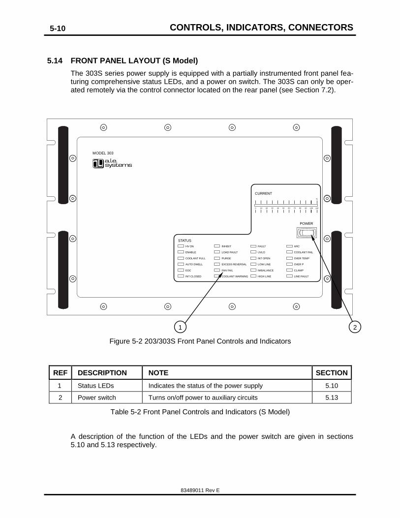
5.14 FRONT PANEL LAYOUT (S Model)
The 303S series power supply is equipped with a partially instrumented front panel fea-turing comprehensive status LEDs, and a power on switch. The 303S can only be oper-ated remotely via the control connector located on the rear panel (see Section 7.2).
STATUS
110
%
10080 90706050403020100
CURRENT
POWER
HV ON
ENABLE
COOLANT FULL
AUTO DWELL
EOC FAN FAIL
INT CLOSED
INHIBIT
LOAD FAULT
PURGE
EXCESS REVERSAL
COOLANT WARNING
FAULT
UVLO
INT OPEN
LOW LINE
IMBALANCE
HIGH LINE
ARC
COOLANT FAIL
OVER TEMP
OVER P
CLAMP
LINE FAULT
MODEL 303
Figure 5-2 203/303S Front Panel Controls and Indicators
REF DESCRIPTION NOTE SECTION
1 Status LEDs Indicates the status of the power supply 5.10
2 Power switch Turns on/off power to auxiliary circuits 5.13
Table 5-2 Front Panel Controls and Indicators (S Model)
A description of the function of the LEDs and the power switch are given in sections 5.10 and 5.13 respectively.
1 2
CONTROLS, INDICATORS, CONNECTORS
83489011 Rev E
5-11
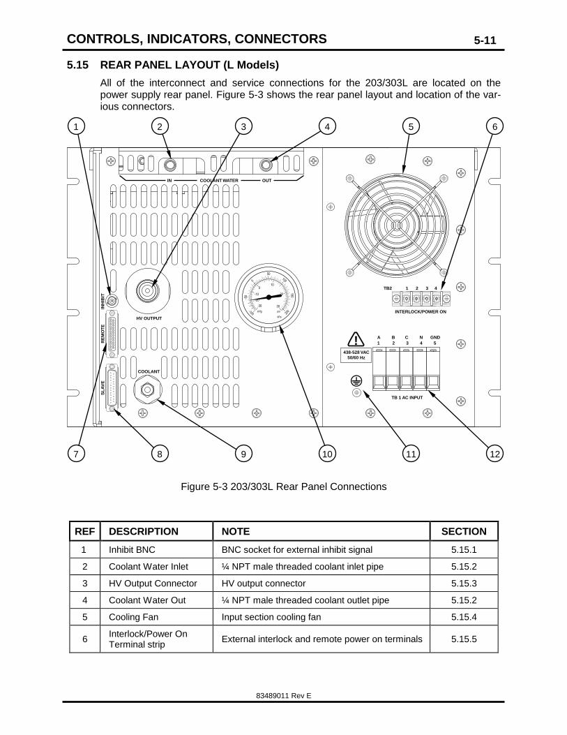
5.15 REAR PANEL LAYOUT (L Models)
All of the interconnect and service connections for the 203/303L are located on the power supply rear panel. Figure 5-3 shows the rear panel layout and location of the var-ious connectors.
INH
IBIT
RE
MO
TE
COOLANT
HV OUTPUT
TB 1 AC INPUT
INTERLOCK/POWER ON
TB2 1 2 3 4
A B C N GND
1 2 3 4 5
COOLANT WATERIN OUT
SL
AV
E
inHg psi
kPa
-30
-100
-50
15050
0
200
100
-20
-10
010
20
30
!438-528 VAC
50/60 Hz
Figure 5-3 203/303L Rear Panel Connections
REF DESCRIPTION NOTE SECTION
1 Inhibit BNC BNC socket for external inhibit signal 5.15.1
2 Coolant Water Inlet ¼ NPT male threaded coolant inlet pipe 5.15.2
3 HV Output Connector HV output connector 5.15.3
4 Coolant Water Out ¼ NPT male threaded coolant outlet pipe 5.15.2
5 Cooling Fan Input section cooling fan 5.15.4
6 Interlock/Power On Terminal strip
External interlock and remote power on terminals 5.15.5
12 AC input terminal AC input terminal block 5.15.10
Table 5-3 203/303L Rear panel Functions
The function of each item in Table 5-3 is described in the following sections.
5.15.1 INHIBIT BNC (Ref 1)
The inhibit BNC input is a standard BNC socket that allows an external connection to a pulse generator or control system and gives the user control of the power supply output current. A logic 1 (10-15V) input will inhibit the supply (shuts off the output current) and a logic 0 (ground or open) allows the supply to operate.
5.15.2 Coolant Water Inlet/Outlet (Ref 2/4)
¼ NPT male threaded pipe connection for external cooling water supply.
5.15.3 HV Output Connector
Connector socket for mating HV cable supplied with unit. The connector should be kept clean and free from debris at all times.
5.15.4 Cooling Fan
Although the supply is water cooled a small cooling fan is used to cool the AC input cir-cuitry. Allow at least 5 inches of clearance and do not obstruct clear air flow around the fan.
5.15.5 Interlock/Power On Terminal strip
Provides an external connection for the customer to allow both interlock and remote power on functions to be controlled. The interlock terminals should be connected to any safety interlock circuitry in the power supply installation. The remote power on terminals are wired in series with the front panel ON switch, and can be used as a remote
ON/OFF switch if the front panel switch is left in the ON position. Note: The Inter-
lock/remote power on terminals are connected to floating chassis referenced
24VAC circuits and should never be connected to ground. Solid state relays
should not be used to control interlock or remote power on terminals.
5.15.6 Remote connector
A 25 pin D-sub female connector that allows remote operation and monitoring of all power supply functions when the unit is operated in REMOTE mode.
5.15.7 Slave connector
A 25 pin D-sub male connector that allows connection of a slave supply for increased power operation. Coolant service valve.
CONTROLS, INDICATORS, CONNECTORS
83489011 Rev E
5-13
5.15.8 Tank pressure gauge
The tank pressure gauge indicates the pressure inside the coolant filled HV assembly. With the power supply non operating at room temperature the gauge should show a vacuum between 10 and 15in Hg. With the supply operating at full power the gauge should read between 10 and 15PSI.
5.15.9 Safety ground
10-32 safety ground screw installed in chassis. Should be used for additional safety ground cable between supply and load circuit.
5.15.10 AC input terminal
Main AC input power terminal block see section 4.5 for further details.
5.15.11 Coolant service valve
External valve to allow topping up of the HV tank with coolant without the need for re-moving the top cover. Do not undertake this procedure without contacting the factory.
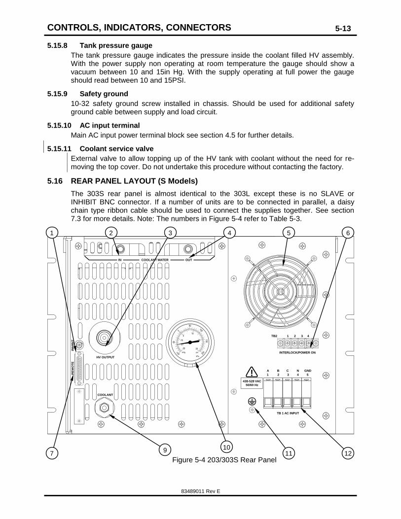
5.16 REAR PANEL LAYOUT (S Models)
The 303S rear panel is almost identical to the 303L except these is no SLAVE or INHIBIT BNC connector. If a number of units are to be connected in parallel, a daisy chain type ribbon cable should be used to connect the supplies together. See section 7.3 for more details. Note: The numbers in Figure 5-4 refer to Table 5-3.
INH
IBIT
RE
MO
TE
COOLANT
HV OUTPUT
TB 1 AC INPUT
INTERLOCK/POWER ON
TB2 1 2 3 4
A B C N GND
1 2 3 4 5
COOLANT WATERIN OUT
inHg psi
kPa
-30
-100
-50
150
50
0
200
100
-20
-10
010
20
30
!438-528 VAC
50/60 Hz
Figure 5-4 203/303S Rear Panel
10 12 11
1 2 3 4 5 6
7 9
CONTROLS, INDICATORS, CONNECTORS
83489011 Rev E
6-14
6. OPTIONAL FEATURES
The 203/303 series power supplies can be ordered with a number of optional features which are explained in the following paragraphs.
6.1 LOW ENABLE OPTION (-EN)
All model 203/303 power supplies are equipped with an Enable or HV ON/OFF signal as part of the remote interface. The standard ENABLE logic is a 12-15V signal turns HV ON and 0V or open turns HV OFF. The EN option replaces the standard logic levels with 12-15V = HV OFF and 0V or Open = HV ON.
6.2 5V PROGRAMMING OPTION (-5V)
All model 203/303 power supplies are equipped with an Analog output voltage program signal (Vprogram) as part of the remote interface. The program level is 0-10V input is equal to 0 to 100% of rated output voltage. The -5V option replaces the standard programming so that 0-5V input delivers 0-100% of rated voltage at the output. Note that the Analog Out and Voltage M Out signals remain scaled at 0-10V with 5V option installed.
6.3 LATCHING OVERLOAD PROTECTION OPTION (-LP)
Standard model 203 and 303 series capacitor charging supplies are equipped with a Load Fault or Overload protection circuit. This circuit causes the power supply to shut down and indicate a LOAD FAULT condition if the output voltage does not reach the programmed voltage within 500ms. The LOAD FAULT condition automatically clears af-ter a further 500ms, and the supply continues charging the load in 500ms intervals until the programmed voltage is reached.
If the LP option is installed, the power supply still shuts down if the output voltage does not reach the programmed voltage within 500ms, and the unit stays latched OFF indicat-ing a LOAD FAULT, which requires a reset signal before it will restart.
6.4 CONTINUOUS DC OPTION (-DC)
Model 203 or 303 power supplies equipped with the DC option should not be op-
erated in parallel without first contacting the factory.
The DC option is specified when a 203 or 303 series power supply is used to power a continuous DC load such as an RF tube, amplifier, DC-DC converter, or similar load where the output voltage and current is continuously on.
All model 203 and 303 power supplies equipped with the DC option have –DC in the product description, for example – 303L-50KV-POS-DC-3P480, 203L-7KV-POS-DC-3P400.
203 and 303 -DC supplies are factory modified to have the OVERLOAD function defeat-ed, the output current adjusted for the appropriate power level (see power ratings in Section 2.1), and a different final test procedure is employed.
When operating a model 203 or 303 power supply in a DC application, the customer must add an external filter capacitor to the load circuit to ensure the output ripple is suit-able for the application. Model 203 and 303-DC power supplies must never be operated into a resistive or other load without an external filter capacitor, otherwise damage may occur to the High Voltage Output. For more details on continuous DC operation and filter capacitor sizing and selection, please refer to our online App Note 505 which can be downloaded at:
The remote sense option can be specified when the output voltage accuracy or stability requirements of the application cannot be met by the internal voltage sensing compo-nents. It allows the power supply’s output voltage sense signal to be provided by an ex-ternal voltage divider.
Power supplies equipped with the remote sense option have an additional BNC con-nector located on the rear panel adjacent to remote/slave control connectors. The BNC connector is labeled HVS (High Voltage Sense).
The typical remote sense input is configured for a 1000:1 divide ratio external probe,
and has a 1M input impedance with a capacitance of 20-50pF. Other divide ratios and impedances can be configured upon request. Contact the factory to confirm the exact remote sense input requirements.
The remote sense input must be connected for correct operation of the power supply. If the supply is operated without the remote sense signal connected, the output will not be uncontrolled, but it will deliver approximately 10% higher output when set to the maxi-mum programmed voltage.
6.6 CURRENT PROGRAMMING (-CP)
Power supplies equipped with the Current Programming option, allow the user to pro-gram the output current between approximately 10% and 100% of rated current. A mod-el 203/303L equipped with the CP option has an addition control potentiometer located below the voltage control potentiometer, and a current program pin on the remote inter-face (Pin 18). A 203/303S equipped with this feature has the control signal on the re-mote interface only. This feature is useful in continuous DC units, but can also be speci-fied in capacitor charging applications.
6.7 LONG CHARGE OPERATION (-LCA)
The long charger operation option should be specified if the 203/303 power supply is designed to be used to charge a large capacitive over a period of 1second or more. The LCA option controls the charger output current such that the load charges in fastest possible time without exceeding the average power rating of the unit. When this option is specified, the charge voltage curve will ramp in the conventional manner from 0 to 50% of rated voltage where the charge current is constant. Then at voltages above 50% of rated, the charge current is gradually reduced so the unit operates as a constant power source with a power limit equivalent to the average power rating of the unit.
With the LCA option installed, the Iprogram, and Current meter Output signals are not scaled at 0-10V=0-100%, please contact the factory for more details.
The 203/303 power supply is designed for operation in two modes. The first mode is lo-cal, where the power supply is operated using the front panel controls. Local operation is only possible with the L model supply. The second mode is remote, where control sig-nals are passed via the 25pin remote connector. Remote operation is possible with all 203/303 model power supplies (L and S).
7.1 LOCAL OPERATION (203/303L only)
The model 203/303L has full front panel instrumentation and controls for use in labora-tory, prototype or OEM systems. The front panel controls include power on/off, re-mote/local key switch, HV on/off push-buttons, output voltage adjust, digital voltage and current meters, and status indicators. An internal AC contactor is included which is con-trolled by the front panel power switch and the interlock terminals on the rear of the unit. A BNC connector is provided on the rear panel for easily connecting a pulsed INHIBIT signal when operating from the front panel. The model 203/303L can be operated as a "master" unit in parallel with several model 203/303S or "slave" units for increased out-put power. Refer to Section 7.3 Parallel Operation.
After all external AC input, cooling, and load connections have been correctly made and the high voltage cable properly terminated at the load, the power supply is ready to op-erate.
NOTE: The 203/303 series power supplies are not designed to operate into an open cir-cuit load. Operating the supply with no external load capacitor could result in damage to the high voltage output section and would void the warranty.
CAUTION
HIGH VOLTAGES MAY POTENTIALLY EXIST FROM
THIS POINT FORWARD
To operate the supply, follow the steps below:
1. Turn "HV Level Adjust" control fully CCW.
2. Ensure key switch is in the OFF position.
3. Turn on AC power, "POWER" switch.
The fan should be running. The front panel LED's will light and reset. The INHIBIT and HV OFF LEDs should be illuminated. The END OF CHARGE LED may or may not be on at this time. The INTERLOCK OPEN LED should be extinguished.
4. Turn key switch to the LOCAL position. Push the HV ON button, slowly turn the high voltage adjust level to the desired output voltage. Note that at any point in stopping the adjustment, the end of charge light will illuminate.
5. When the desired output voltage is reached, the load switch should now operate and the power supply will begin charging the load at the rated power level.
After the load has been discharged the AUTOINHIBIT function will inhibit the output cur-rent for a short time before the load is re-charged. Alternatively an external inhibit signal can be connected to the rear panel mounted BNC connector.
OPERATING INSTRUCTIONS
83489011 Rev E
7-18
To turn OFF the power supply depress the OFF button or use the INHIBIT input. Open-ing the interlock terminals will also cause the power supply to turn off. In this case the unit can only be turned back on after the interlock has been closed and the OFF button depressed to RESET the fault. Any other fault occurring in the internal protection circuit-ry will interrupt the power supply's operation causing it to turn OFF.
For a full explanation of each control and indicator refer to Section 5.
7.2 REMOTE OPERATION (All models)
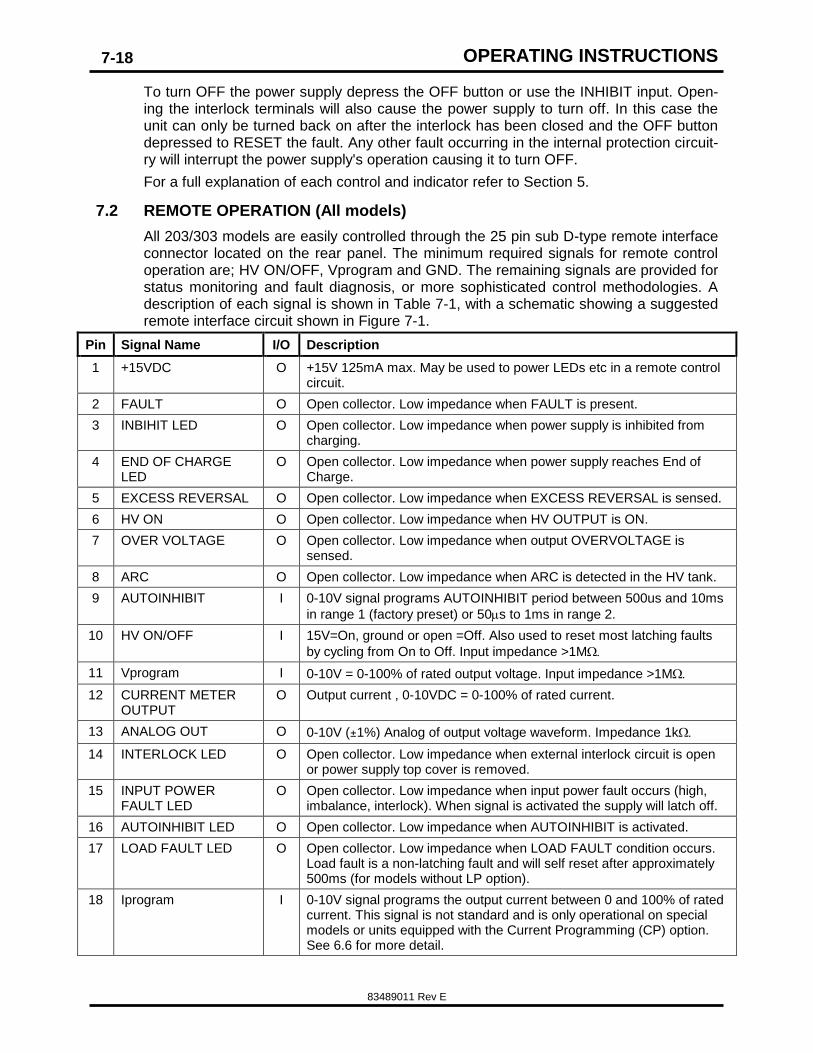
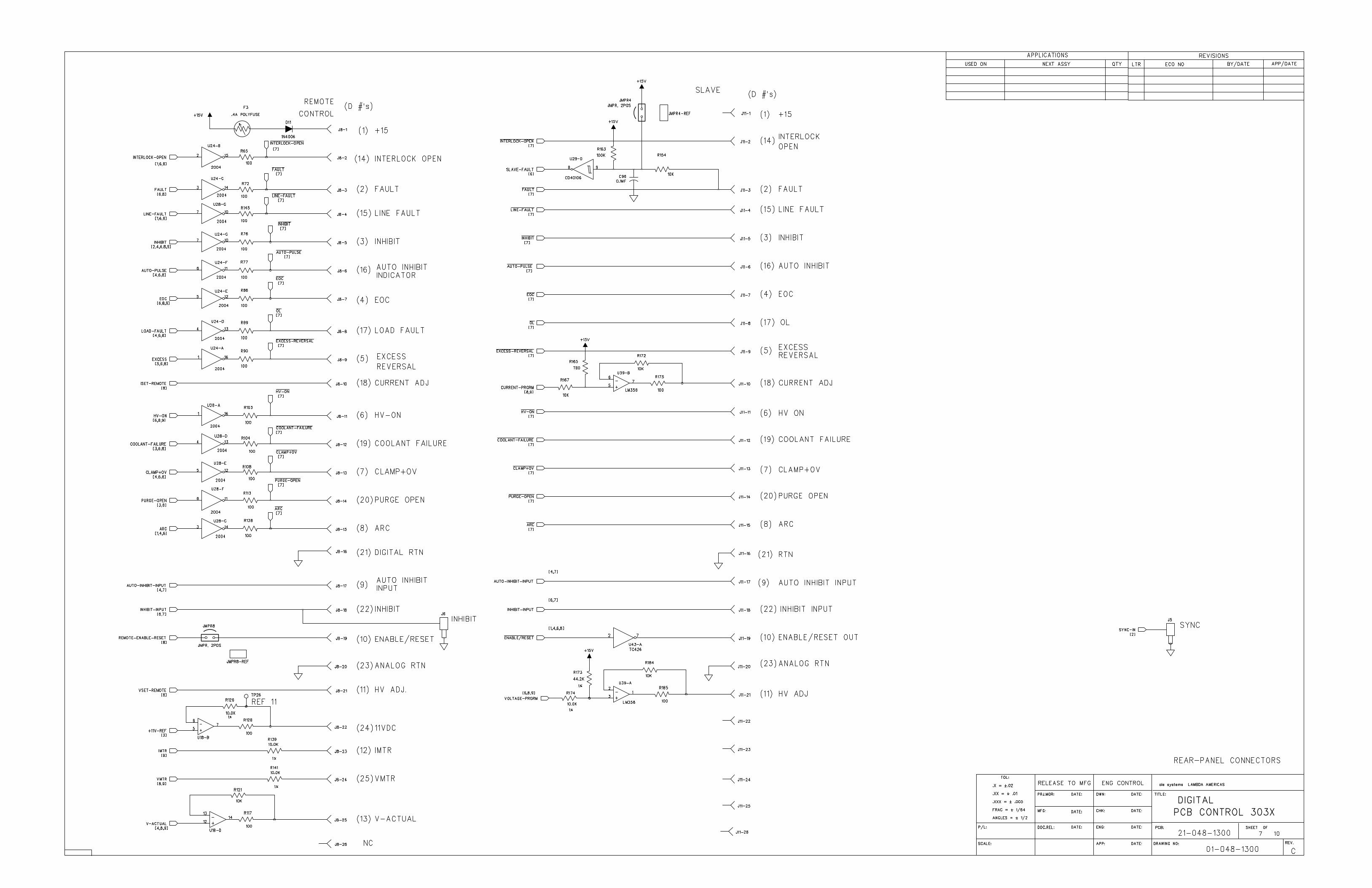
All 203/303 models are easily controlled through the 25 pin sub D-type remote interface connector located on the rear panel. The minimum required signals for remote control operation are; HV ON/OFF, Vprogram and GND. The remaining signals are provided for status monitoring and fault diagnosis, or more sophisticated control methodologies. A description of each signal is shown in Table 7-1, with a schematic showing a suggested remote interface circuit shown in Figure 7-1.
Pin Signal Name I/O Description
1 +15VDC O +15V 125mA max. May be used to power LEDs etc in a remote control circuit.
2 FAULT O Open collector. Low impedance when FAULT is present.
3 INBIHIT LED O Open collector. Low impedance when power supply is inhibited from charging.
4 END OF CHARGE LED
O Open collector. Low impedance when power supply reaches End of Charge.
5 EXCESS REVERSAL O Open collector. Low impedance when EXCESS REVERSAL is sensed.
6 HV ON O Open collector. Low impedance when HV OUTPUT is ON.
7 OVER VOLTAGE O Open collector. Low impedance when output OVERVOLTAGE is sensed.
8 ARC O Open collector. Low impedance when ARC is detected in the HV tank.
9 AUTOINHIBIT I 0-10V signal programs AUTOINHIBIT period between 500us and 10ms
in range 1 (factory preset) or 50s to 1ms in range 2.
10 HV ON/OFF I 15V=On, ground or open =Off. Also used to reset most latching faults
by cycling from On to Off. Input impedance >1M
11 Vprogram I 0-10V = 0-100% of rated output voltage. Input impedance >1M
12 CURRENT METER OUTPUT
O Output current , 0-10VDC = 0-100% of rated current.
13 ANALOG OUT O 0-10V (±1%) Analog of output voltage waveform. Impedance 1k
14 INTERLOCK LED O Open collector. Low impedance when external interlock circuit is open or power supply top cover is removed.
15 INPUT POWER FAULT LED
O Open collector. Low impedance when input power fault occurs (high, imbalance, interlock). When signal is activated the supply will latch off.
16 AUTOINHIBIT LED O Open collector. Low impedance when AUTOINHIBIT is activated.
17 LOAD FAULT LED O Open collector. Low impedance when LOAD FAULT condition occurs. Load fault is a non-latching fault and will self reset after approximately 500ms (for models without LP option).
18 Iprogram I 0-10V signal programs the output current between 0 and 100% of rated current. This signal is not standard and is only operational on special models or units equipped with the Current Programming (CP) option. See 6.6 for more detail.
OPERATING INSTRUCTIONS
83489011 Rev E
7-19
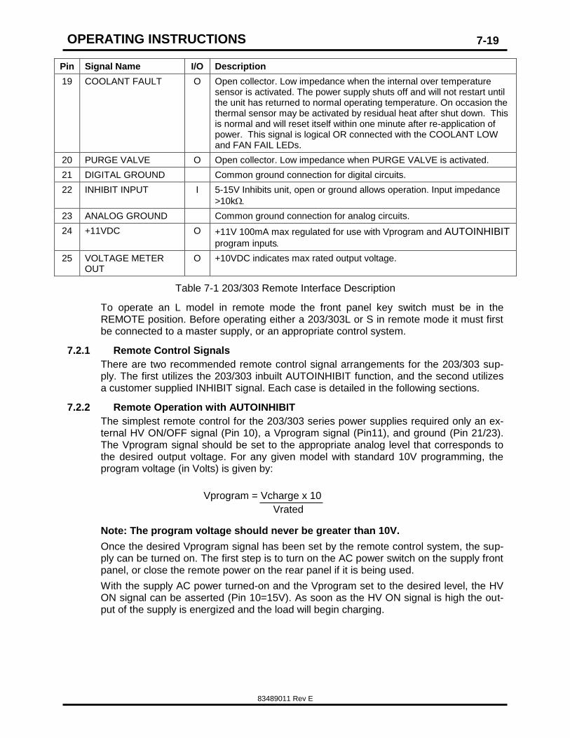
Pin Signal Name I/O Description
19 COOLANT FAULT O Open collector. Low impedance when the internal over temperature sensor is activated. The power supply shuts off and will not restart until the unit has returned to normal operating temperature. On occasion the thermal sensor may be activated by residual heat after shut down. This is normal and will reset itself within one minute after re-application of power. This signal is logical OR connected with the COOLANT LOW and FAN FAIL LEDs.
20 PURGE VALVE O Open collector. Low impedance when PURGE VALVE is activated.
21 DIGITAL GROUND Common ground connection for digital circuits.
22 INHIBIT INPUT I 5-15V Inhibits unit, open or ground allows operation. Input impedance
>10k
23 ANALOG GROUND Common ground connection for analog circuits.
24 +11VDC O +11V 100mA max regulated for use with Vprogram and AUTOINHIBIT
program inputs
25 VOLTAGE METER OUT
O +10VDC indicates max rated output voltage.
Table 7-1 203/303 Remote Interface Description
To operate an L model in remote mode the front panel key switch must be in the REMOTE position. Before operating either a 203/303L or S in remote mode it must first be connected to a master supply, or an appropriate control system.
7.2.1 Remote Control Signals
There are two recommended remote control signal arrangements for the 203/303 sup-ply. The first utilizes the 203/303 inbuilt AUTOINHIBIT function, and the second utilizes a customer supplied INHIBIT signal. Each case is detailed in the following sections.
7.2.2 Remote Operation with AUTOINHIBIT
The simplest remote control for the 203/303 series power supplies required only an ex-ternal HV ON/OFF signal (Pin 10), a Vprogram signal (Pin11), and ground (Pin 21/23). The Vprogram signal should be set to the appropriate analog level that corresponds to the desired output voltage. For any given model with standard 10V programming, the program voltage (in Volts) is given by:
Note: The program voltage should never be greater than 10V.
Once the desired Vprogram signal has been set by the remote control system, the sup-ply can be turned on. The first step is to turn on the AC power switch on the supply front panel, or close the remote power on the rear panel if it is being used.
With the supply AC power turned-on and the Vprogram set to the desired level, the HV ON signal can be asserted (Pin 10=15V). As soon as the HV ON signal is high the out-put of the supply is energized and the load will begin charging.
Vprogram = Vcharge x 10
Vrated
OPERATING INSTRUCTIONS
83489011 Rev E
7-20
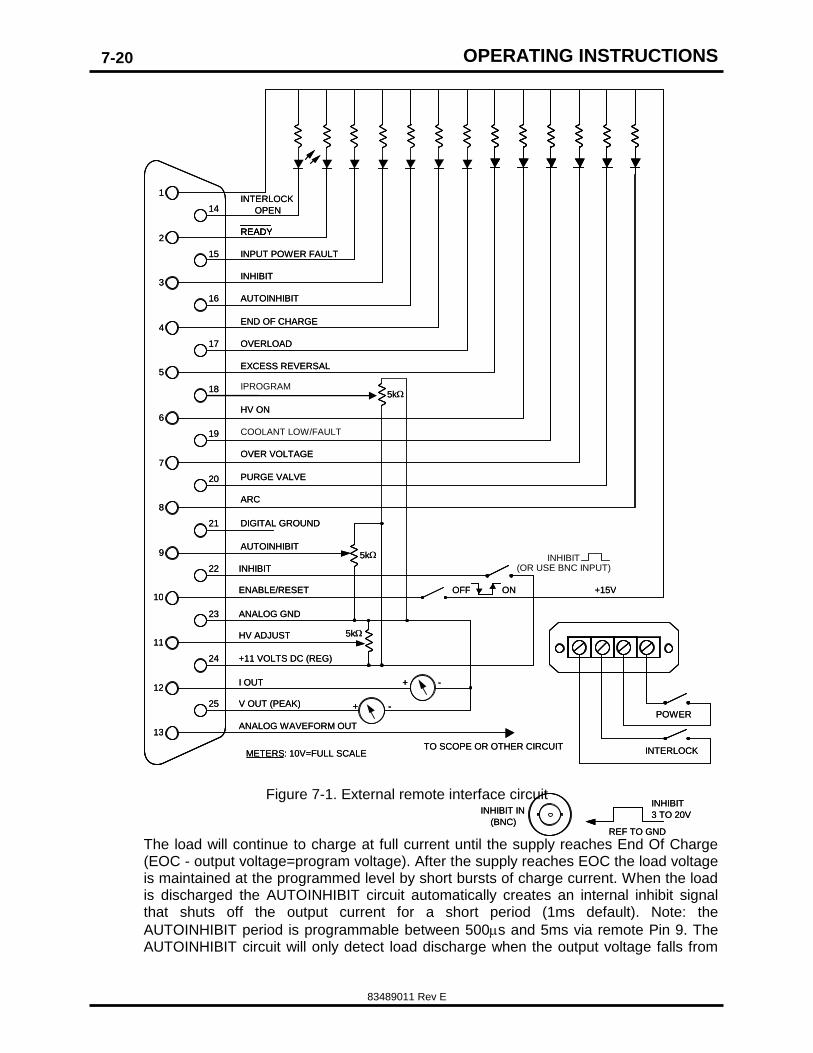
Figure 7-1. External remote interface circuit
The load will continue to charge at full current until the supply reaches End Of Charge (EOC - output voltage=program voltage). After the supply reaches EOC the load voltage is maintained at the programmed level by short bursts of charge current. When the load is discharged the AUTOINHIBIT circuit automatically creates an internal inhibit signal that shuts off the output current for a short period (1ms default). Note: the
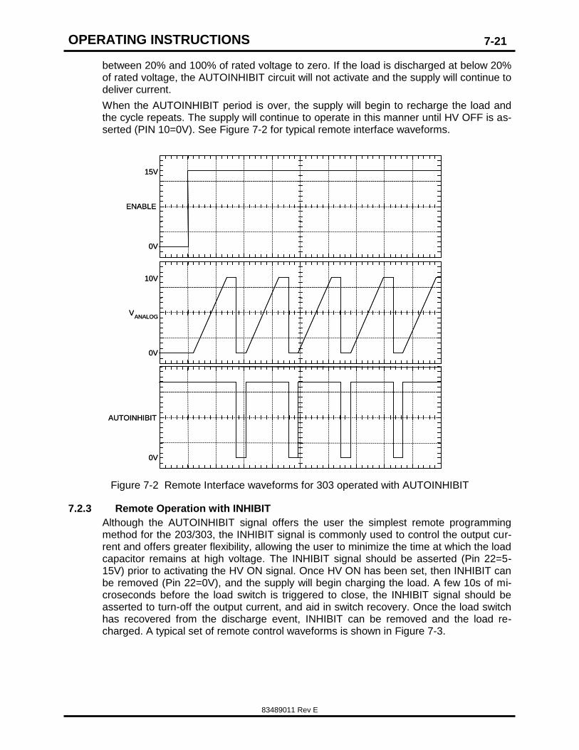
AUTOINHIBIT period is programmable between 500s and 5ms via remote Pin 9. The AUTOINHIBIT circuit will only detect load discharge when the output voltage falls from
PURGE VALVE
25
22
23
24
21
1
2
3
4
5
6
7
8
9
10
11
12
13
14
15
16
17
18
19
20
INTERLOCK OPEN
READY
INPUT POWER FAULT
AUTOINHIBIT
INHIBIT
END OF CHARGE
OVERLOAD
EXCESS REVERSAL
HV ON
OVER VOLTAGE
PURGE VALVE
ARC
DIGITAL GROUND
AUTOINHIBIT
(OR USE BNC INPUT)
+15V
5k
ENABLE/RESET
INHIBIT
OFF ON
ANALOG GND
HV ADJUST
+11 VOLTS DC (REG)
V OUT (PEAK) + -
+ -
TO SCOPE OR OTHER CIRCUIT
INHIBIT IN (BNC)
INHIBIT 3 TO 20V
REF TO GND
POWER
INTERLOCK METERS : 10V=FULL SCALE
ANALOG WAVEFORM OUT
I OUT
25
22
23
24
21
1
2
3
4
5
6
7
8
9
10
11
12
13
14
15
16
17
18
19
20
INTERLOCK OPEN
READY READY
INPUT POWER FAULT
AUTOINHIBIT
INHIBIT
END OF CHARGE
OVERLOAD
EXCESS REVERSAL
HV ON
COOLANT LOW/FAULT
OVER VOLTAGE
ARC
DIGITAL GROUND
AUTOINHIBIT INHIBIT
+15V
5k
5k 5k
ENABLE/RESET
INHIBIT
OFF ON
ANALOG GND
HV ADJUST
+11 VOLTS DC (REG)
V OUT (PEAK) + - + -
+ - + -
TO SCOPE OR OTHER CIRCUIT
INHIBIT IN (BNC)
INHIBIT 3 TO 20V
REF TO GND
POWER
INTERLOCK METERS : 10V=FULL SCALE
ANALOG WAVEFORM OUT
I OUT
IPROGRAM 5k 5k
OPERATING INSTRUCTIONS
83489011 Rev E
7-21
between 20% and 100% of rated voltage to zero. If the load is discharged at below 20% of rated voltage, the AUTOINHIBIT circuit will not activate and the supply will continue to deliver current.
When the AUTOINHIBIT period is over, the supply will begin to recharge the load and the cycle repeats. The supply will continue to operate in this manner until HV OFF is as-serted (PIN 10=0V). See Figure 7-2 for typical remote interface waveforms.
Figure 7-2 Remote Interface waveforms for 303 operated with AUTOINHIBIT
7.2.3 Remote Operation with INHIBIT
Although the AUTOINHIBIT signal offers the user the simplest remote programming method for the 203/303, the INHIBIT signal is commonly used to control the output cur-rent and offers greater flexibility, allowing the user to minimize the time at which the load capacitor remains at high voltage. The INHIBIT signal should be asserted (Pin 22=5-15V) prior to activating the HV ON signal. Once HV ON has been set, then INHIBIT can be removed (Pin 22=0V), and the supply will begin charging the load. A few 10s of mi-croseconds before the load switch is triggered to close, the INHIBIT signal should be asserted to turn-off the output current, and aid in switch recovery. Once the load switch has recovered from the discharge event, INHIBIT can be removed and the load re-charged. A typical set of remote control waveforms is shown in Figure 7-3.
AUTOINHIBIT
0V
15V
ENABLE
0V
10V
V ANALOG
0V
AUTOINHIBIT
0V
15V
ENABLE
0V
10V
V ANALOG
0V
OPERATING INSTRUCTIONS
83489011 Rev E
7-22
0V
15V
ENABLE
0V
10V
VANALOG
0V
INHIBIT
15V
0V
15V
ENABLE
0V
10V
VANALOG
0V
INHIBIT
15V
Figure 7-3 Remote Interface waveforms for 303 operated with INHIBIT
7.3 Parallel Operation
The 203/303 series capacitor charging power supplies are constant current sources, and can be connected in parallel for applications requiring increased power. To operate more than one unit in parallel all that is required is a parallel control cable, and to con-nect the HV output cables together at the load. Either model 203/303L or 203/303S or any combination of units can be operated in parallel. If at least one model 203/303L is connected in a parallel system then the system can be operated without an external controller by using the 203/303L as a master supply in local mode.
If status, voltage, and current displays/measurements are required individually for each supply in a parallel system then the ‘daisy chain’ control cable is not appropriate, and each unit must be individually connected to a remote control system.
7.3.1 Parallel system comprising 203/303L supplies
If all of the parallel units are L model supplies then one unit should be operated as the master supply in either local or remote mode. The other parallel supplies can be con-nected to the SLAVE 25-pin D-sub connector on the master unit rear panel (refer to Fig-ure 7-4). The SLAVE control cable can be a pin-to-pin ribbon or other cable that is ‘daisy chained’ to the REMOTE connector on each of the SLAVE supplies. Note: The master 203/303L supply in a parallel system only displays the status, voltage, and current out-
OPERATING INSTRUCTIONS
83489011 Rev E
7-23
put for that unit, not for the entire system. The slave supplies will also display the volt-age and current only for that specific unit.
7.3.2 Parallel system comprising both 203/303L and 203/303S supplies
For a system comprising both 203/303L and S units, a single L model should be operat-ed as a master in either local or remote mode. The other parallel supplies can be con-nected to the SLAVE 25-pin D-sub connector on the master unit rear panel (refer to Fig-ure 7-4). The SLAVE control cable can be a pin-to-pin ribbon or other cable that is ‘daisy chained’ to the REMOTE connector on each of the SLAVE supplies.
7.3.3 Parallel system comprising 203/303S supplies
A system comprising only model 203/203S supplies must be operated from a control system. The control system should be connected using a pin-to-pin ribbon or other cable that is ‘daisy chained’ to the REMOTE connector on each of the 203/303S supplies in the system.
Figure 7-4 Parallel Operation Connections
OPERATING INSTRUCTIONS
83489011 Rev E
7-24
NOTES:
APPLICATION NOTES
83489011 Rev E
8-25
8. APPLICATION NOTES
The 203/303 series power supplies are extremely powerful high voltage power sources and great care should be taken when connecting and operating these units. In order to aid installation design and number of application notes have been produced to aid the design engineer with certain load circuit component rating and selection. The latest ver-sions of these application notes are available for download at the Lambda web site (http://us.tdk-lambda.com/hp/product_html/high_volt.htm).
The following App Notes were available at the time this manual was produced. These documents are continually being improved and expanded to always check for the latest revision on-line.
APP Note 500: Calculating Capacitor Charge Time.
APP Note 502: Calculating AC Line Currents.
APP Note 505: Charging units as Continuous Output DC Supplies.
APP Note 507: Charging Large Load Capacitors.
APP Note 509: What is Regulation and Repeatability?
APP Note 513: Power Factor Correction.
APP Note 517: Protection Against Voltage Reversal.
If there are any other application issues or questions that are not covered in these
Application Notes, or elsewhere in this manual, please do not hesitate to contact
the factory and our team of experienced HV application engineers.