54
b * Service Manual 30C and 45C Load Push and Load Push/Pull Serial Numbers 667310 through 672356 0 Manual Number 667444 R-2 cascad& Cascade is a Registered Trademark of Cascade Corporation

b * Service
Manual 30C and 45C Load Push and Load Push/Pull Serial Numbers 667310 through 672356
0 Manual Number 667444 R-2
cascad& Cascade is a Registered Trademark of Cascade Corporation

Contents
Page Number
INTRODUCTION. Section 1 ....................... 3-1 INSTALLATION INSTRUCTIONS, Section 2 ....... 3-2
Load Push and Load Push/Pull (Non-Sideshifting) 3-2 Load Push and Load Push/Pull (Sideshifting) ..... 3-4
PERIODIC MAINTENANCE, Section 3 ............ 3-9 TROUBLESHOOTING, Section 4 ................. 3-10
Hosing Diagrams and Schematics Non-sideshifting begins ...................... 3-12 Sideshifting without Solenoid begins .......... 3-14 Sideshifting with Solenoid begins ............. 3-19 Sideshifting with Adjustable Platens begins ... 3-23 Sideshifting with Sheet Retainer begins ....... 3-25 Sideshifting Platens begins ................... 3-27
Troubleshooting the Push/Pull Circuit ........... 3-29 Troubleshooting the Sideshift Circuit ............ 3-32 Troubleshooting the Adjustable Platen Circuit ... 3-33 Troubleshooting the Sheet Retainer Circuit ...... 3-34 Troubleshooting the Sideshifting Platen Circuit ... 3-14 Troubleshooting the (Electric) Hydraulic Faceplate Stop Group ........................... 3-35
SERVICE, Section 5 ............................... 3-37 Attachment Removal and Installation ............ 3-37 Faceplate and Pantograph Arms
Disassembly .................................. 3-38 Service and Reassembly ...................... 3-39 Gripper Mechanism Disassembly ............. 3-39
Valve Removal and Installation ...................... 3-40 Disassembly and Inspection .
Cylinders Removal . . General Procedures Service .
Junction Block Removal and Installation Solenoid Valve
Removal and Installation Service . . .
Platens Removal and Installation . . Inspection . .
Manual/Electric(Hydraulic) FaceplateStopGroups Removal and Installation . Adjustment . .
Sheet Retainer Mechanism Removal and Installation
3-40
3-41 3-42 3-43 3-45
3-46 3-47
3-48 & 49 3-48 & 49
3-50 3-50
3-51
Form 5181 Rev. 1 i

Section 1 Introduction
1.1
1.2
This service manual provides the installation instructions, periodic maintenance requirements, troubleshooting procedures, service procedures, and standard labor times for Cascade’s C-series load push and load push/pull.
Truck System Requirements
Truck Relief Valve Setting: 2000 psi, maximum.
Volume: 30C:‘3-5 GPM 45C: 5-7 GPM
Recommended hose and fitting size: No. 6 (% inch, I.D.).
Truck carriage must conform to the industrial Truck Association (ITA) dimensional standards as shown in the chart at the right.
Make sure the truck carriage is clean and the notches are undamaged.
In order to conform to industry standard practice, the hoses should be connected to the truck auxiliary valve as indicated by the chart at the right.
Special Instructions Definitions
WARNING
A statement preceded by A WARNING is information that should be acted upon to prevent bodily injury. A WARNING is always inside a ruled box.
CAUTION
A statement preceded by CAUTION is information that should be acted upon to prevent machine damage.
IMPORTANT
A statement preceded by IMPORTANT is information that possesses special significance.
NOTE
A statement preceded by NOTE is information that will make your job easier.
s -1 A
1
Mounting
Class I I
Class III
Dimension A (in.1
Min. Max.
14.98 15.00
18.68 18.74
Function, in Motion of the operator’s hand ’ sequence of Attachment when actuating the truck auxil- location to the Movement iary control handle while facing operator the load.
Sideshift Sideshift Right Rearward or Up
Sideshift Left Forward or Down
Push/Pull Pull (rearward) Rearward or Up
Push (forward) Forward or Down
Adjust Platens Platens In Rearward or Up
Platens Out Forward or Down
Sheet Retain Retain Rearward or Up
Release Forward or Down
Sideshift Platens Sideshift Right] Rearward or Up
Sideshift Left Forward or Down
3-1 Form 5181 Rev. 1
Section 2 Installation Instructions 2.1 Load Push and Load Push/Pull
WARNING (Non-Sideshifting)
NOTE: Sideshiftina Load Push and Load Push/Pull Installation begins with paragraph 2.2
WARNING: Rated capacity of the
A truck/attachment combination is a responsibility of the original truck manufacturer and may be less than shown on the attachment nameplate. Consult the truck nameplate.
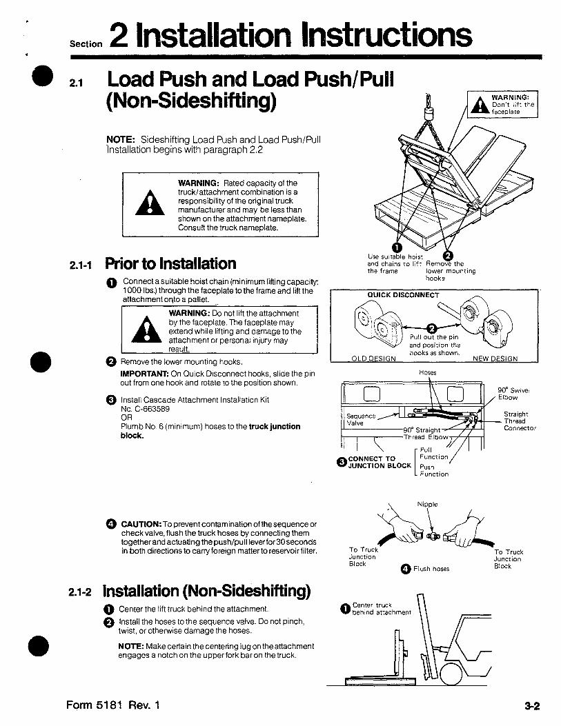
2.1-1 Prior to Installation 0 Connect a suitable hoist chain (minimum lifting capacity:
1000 Ibs.) through the faceplate to the frame and lift the attachment onto a ballet.
WARNING: Do not lift the attachment by the faceplate. The faceplate may
attachment or personal injury may
@ Remove the lower mounting hooks.
IMPORTANT: On Quick Disconnect hooks, slide the pin out from one hook and rotate to the position shown.
0 Install Cascade Attachment Installation Kit No. C-663589 OR Plumb No. 6 (minimum) hoses to the truck junction block.
@ CAUTION: To prevent contamination of thesequence or check valve, flush the truck hoses by connecting them togetherand actuating the push/pull lever for 30 seconds in both directions to carry foreign matter to reservoir filter.
2.1-2 Installation (Non-Sideshifting) 0 Center the lift truck behind the attachment.
0 Install the hoses to the sequence valve. Do not pinch, twrst, or otherwise damage the hoses.
NOTE: Make certain the centering lug on the attachment engages a notch on the upper fork bar on the truck.
and chains to lift Remove the the frame lower mounting
hooks
I QUICK DISCONNECT n I’
Hoses
OJUNCTIO; BLOCK 1 CONNECT TO
L Function
\ Nipple
Junction Block
To Truck Junction
0 Flush hoses Block
Form 5181 Rev. 1 3-2
Section 2 Installation Instructions .
2.1-2 Installation (Non-Sideshifting Cont.)
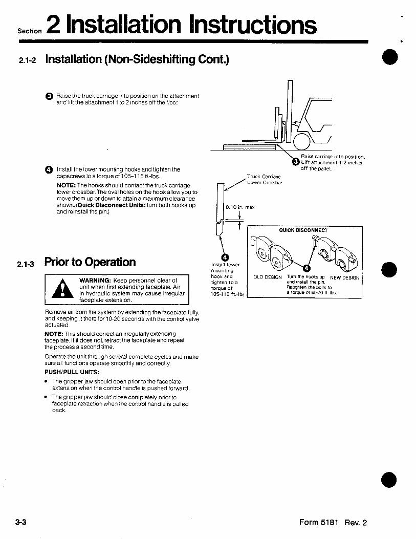
0 Raise the truck carriage into position on the attachment and ltft the attachment 1 to 2 inches off the floor.
0 Install the lower mounting hooks and tighten the capscrews to a torque of 105-l 15 ft.-lbs.
NOTE: The hooks should contact the truck carriage lower crossbar. The oval holes on the hook allow you to move them up or down to attain a maximum clearance shown. (Quick Disconnect Units: turn both hooks up and reinstall the pin.)
Prior to Operation
WARNING: Keep personnel clear of unit when first extending faceplate. Air
Remove air from the system by extending the faceplate fully, and keeping it there for 10-20 seconds with the control valve actuated.
NOTE: This should correct an irregularly extending faceplate. If it does not, retract the faceplate and repeat the process a second time.
Operate the unit through several complete cycles and make sure all functions operate smoothly and correctly.
PUSH/PULL UNITS:
l The gripper jaw should open prior to the faceplate extension when the control handle IS pushed forward
l The gripper jaw should close completely prior to faceplate retraction when the control handle is pulled back.
Raise carriage into position, Lift attachment 1-2 inches off the pallet.
Truck Carriage Lower Crossbar
max
install lower mounting hook and tighten to a torque of 105-l 15 ft..lbs
QUICK DISCONNECT
OLD DESIGN Turn the hooks up NEW DESIGN and install the pin. Retighten the bolts to a torque of 6070 ft.-lbs.
3-3 Form 5181 Rev. 2
Section 2 Installation Instructions .
2.2 Load Push and Load Push/Pull (Sideshifting)
2.2-1 Truck Preparation Skip Steps 1 through 4 if the unit is equipped with Quick Disconnect mounting hooks. TO ATTACH THE SIDESHIFT CYLINDER ANCHOR BRACKET:
Place template in center notch.
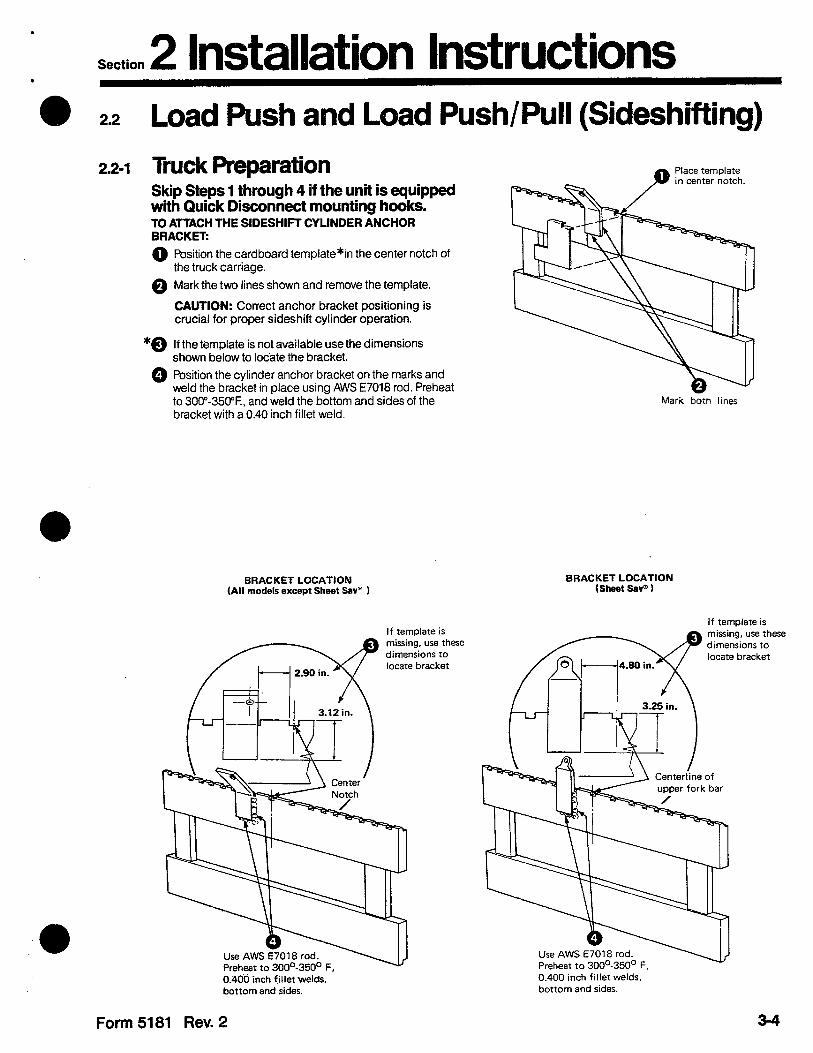
0 Position the cardboard template*in the center notch of the truck carriage.
@ Mark the two lines shown and remove the template.
CAUTION: Correct anchor bracket positioning is crucial for proper sideshift cylinder operation.
*@ If the template is not available use the dimensions shown below to locate the bracket.
0 Position the cylinder anchor bracket on the marks and weld the bracket in place using AWS E7018 rod. Preheat to 300”-350% and weld the bottom and sides of the bracket with a 0.40 inch fillet weld.
Mark both lines
BRACKET LOCATION BRACKET LOCATION
(All models except Sheet Sav” ) (Sheet Sav”)
If template is
Use AWS E7018 rod. Preheat to 300°-350’ F.
;ing, use these ensions to
If temolate is
racket
Centerline of
Use AWS E7018 rod. Preheat to 300°-350’ F. 0.400 inch fillet welds, bottom and sides.
0.406 inch fillet welds, bottom and sides.
Form 5181 Rev. 2
Section 2 Installation Instructions 2.2-1 Truck Preparation (Cont.)
TO INSTALL THE CONTROL KNOB (Solenoid Units Only):
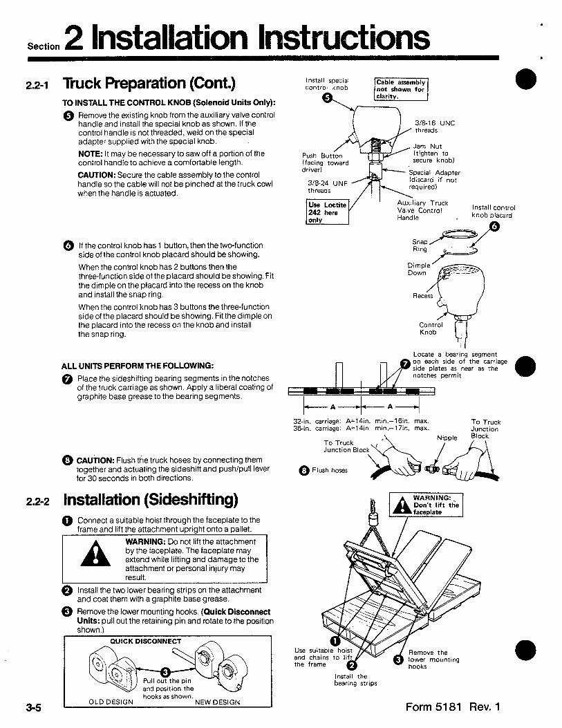
Remove the existing knob from the auxiliary valve control handle and install the special knob as shown. If the control handle is not threaded, weld on the special adapter supplied with the special knob.
NOTE: It may be necessary to saw off a portion of the control handle to achieve a comfortable length.
CAUTION: Secure the cable assembly to the control handle so the cable will not be pinched at the truck cowl when the handle is actuated.
If the control knob has 1 button, then the two-function side of the control knob placard should be showing.
When the control knob has 2 buttons then the three-function side of the placard should be showing. Fit the dimple on the placard into the recess on the knob and install the snap ring.
When the control knob has 3 buttons the three-function side of the placard should be showing. Fit the dimple on the placard into the recess on the knob and install the snap ring.
ALL UNITS PERFORM THE FOLLOWING:
@ Place the sideshifting bearing segments in the notches of the truck carriage as shown. Apply a liberal coating of graphite base grease to the bearing segments.
@ CAUTION: Flush the truck hoses by connecting them together and actuating the sideshift and push/pull lever for 30 seconds in both directions.
WARNING
WARNING
2.2-2 Installation (Sideshifting) 0 Connect a suitable hoist through the faceplate to the
frame and lift the attachment upright onto a pallet.
by the faceplate. The faceplate may
attachment or personal injury may
0 Install the two lower bearing strips on the attachment and coat them with a graphite base grease.
0 Remove the lower mounting hooks, (Quick Disconnect Units: pull out the retaining pin and rotate to the position shown.)
and position the hooks as shown.
Install special control knob
threads
Jam Nut (tighten to secure knob)
Special Adapter (discard if not
! Auxiliary Truck Valve Control Install control
knob placard
Locate a bearing segment on each side of the carriage
[p notches permit srde plates as near as the
0
t-A-t-A-- 32-in. carriage: A=lQin. min.-16in. max. 36-in. carriage: A=14in. min.-17in. max.
To Truck Junction
To Truck ’
0
Junction Bock% Ja
Flush hoses
Install the bearing strips
Form 5181 Rev. 1

Section 2 Installation Instructions l
2.2-2 Installation (Sideshifting Cont.)
0 Center the lift truck behind the attachment and raise the truck carriage into positron on the attachment. Lift the attachment 1 to 2 inches off the pallet.
0 install the lower mounting hooks and tighten the capscrews to a torque of 105-115 ft.-lbs.
NOTE: The hooks should not contact the truck carriage lower crossbar.The oval holes on the hook allow you to move the hook up or down to attain a clearance between the minimum and maximum clearance shown. (Quick Disconnect Units: turn both hooks up and remstall the pin.)
f-l I I
Center the truck behind attachment and raise the carriage into position. II r Lift attachment 1-2 inches off the pallet
Lower Crossbar
Install lower mounting hook and tighten to a toraueof
I QUICK DISCONNECT
I
OLD DESIGN Turn the hooks UP NEW DESIGN and install the pin. Retighten the bolts lo
10511 15 ft.-lb 1 a torque 01 60-70 ft.-lbs
0 Remove the push/pull cylinder rod end pins. Manually pull the faceplate away from the frame.
0 Install the sideshift cylinder rod to the anchor bracket. Push the faceplate back against the frame and reinstall the push/pull cylinder rod end pins.
Remove cylinder rod end pins
Install sideshift cylinder rod to anchor bracket
Form 5181 Rev. 2 3-6

Section 2 Installation Instructions 2.2-2 Installation (Sideshifting Cont.)
TO INSTALL THE HOSES TO THE JUNCTION BLOCK:
IMPORTANT: On solenoid operated attachments your junction block may be mounted on the opposite side from the one shown. You can remove the tubes from the valve and reinstall them on the opposite side of the valve. You must also reverse the hoses, fittings, electric cable and diodes illustrated in grey.
grey can be reversed (moved to opposite side of valve) if junction block is mounted on opposite side.
0 First push the attachment 4 inches (4” = ½ sideshift cylinder stroke) away from the junction block.
NOTE: Open both fittings on the sideshift cylinder to allow the rod to move easily.
@ Remove the reusable fittings from the attachment hoses and cut the hoses to length as shown. (See the enclosed instruction sheet on reusable fittings.)
@ Reinstall the fittings and attach the hoses to the junction block. Position the hose guards to prevent the hoses from being scuffed by the frame.
NOTE: If two junction blocks are used then repeat Steps 8, 9, and 10 for the other side.
nd h
c Jl- Reinstall fittings and connect hoses to junction block. Position hose guards to prevent scuffing of hoses during sideshifting.
Form 5181 Rev. 1 3-7

Section 2 Installation Instructions 2.2-2 Installation (Sideshifting Cont.)
@ The electric cable leading from the attachment should be tied to the hoses to prevent scuffing of the cable during attachment sideshifting. See the electric schematic to complete installation of the cable.
Wires leading from the diode
Cable
7.5 Amp r __
k-- Green (ground)
w Owner-suppled Wiring
TWO-FUNCTION (One-button control knob)
Complete inStallation Of the cable and control knob.
I I -I
cl \ ‘1 Retainer [
i Wemd : Valve I\ II I
\
\ V
Doide
Gre\en (ground)
Wiring Complete installation of the cable and control knob.
THREE-FUNCTION (Two-button control knob)
75Amp
Red Black
\ \
2.2-3 Prior to Operation
Owner supplled Complete installation of the cable and
Remove air from the system by extending the faceplate fully, and keeping it there for lo-20 seconds with the truck valve actuated. NOTE: This should correct an irregularly extended faceplate. If it does not, retract the faceplate and repeat the process a second time. Also sideshift the attachment several times to force air from the sideshift cylinder to the truck reservoir.
Operate the unit through several complete cycles and make sure all functions operate smoothly and correctly.
PUSH/PULL UNITS:
l The gripper jaw should open prior to the faceplate extension when the control handle is pushed forward
l The gripper jaw should close completely prior to faceplate retraction when the control handle is pulled back.
control knob
MREE.FUNCTION (Twmbutton control knob) sheet SW’
Form 5181 Rev. 1 3-8
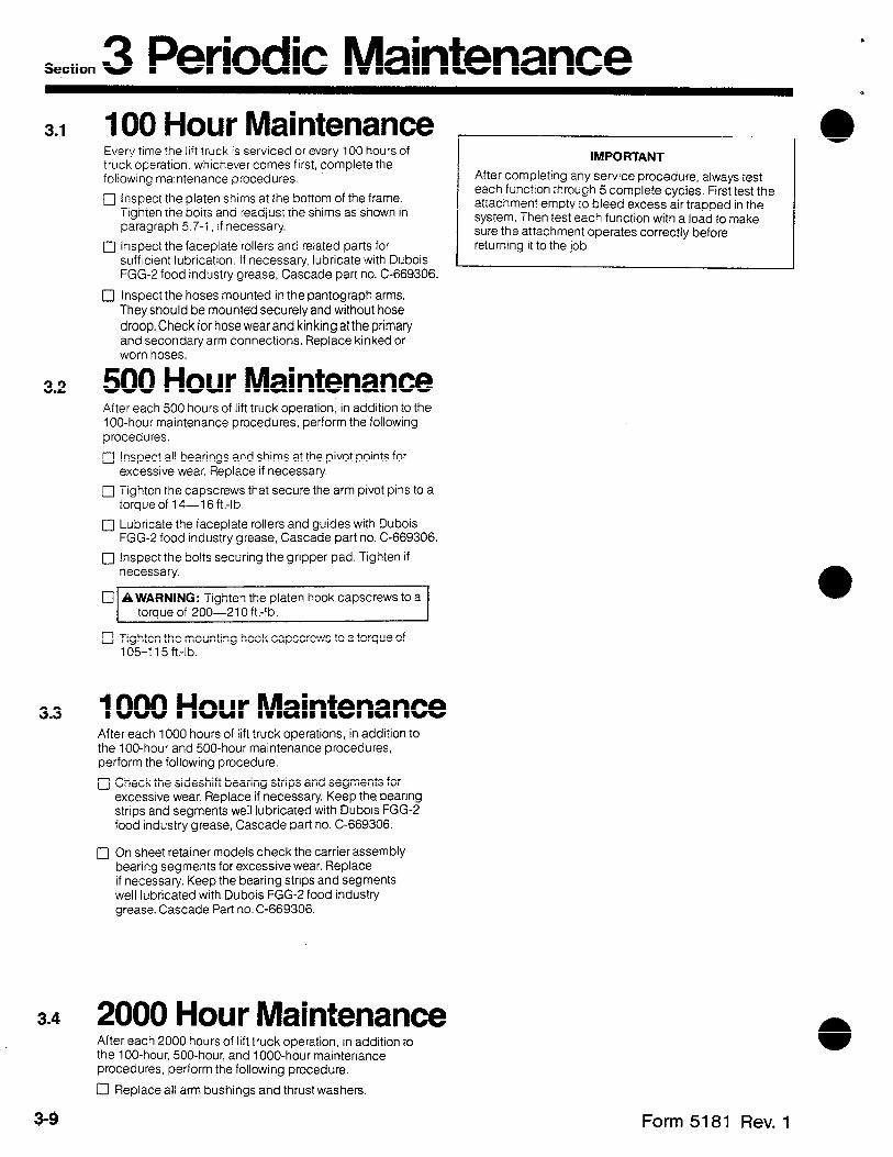
Section 3 Periodic Maintenance 3-1 100 Hour Maintenance
Every time the lift truck is serviced or every 100 hours of truck operation, whichever comes frrst, complete the following maintenance procedures.
c] Inspect the platen shims at the bottom of the frame. Tighten the bolts and readjust the shims as shown in paragraph 5.7-1, If necessary.
0 Inspect the faceplate rollers and related parts for sufficient lubrication. If necessary, lubricate with Dubois FGG-2 food industry grease, Cascade part no. C-669306.
IMPORTANT
After completing any service procedure, always test each function through 5 complete cycles. First test the attachment empty to bleed excess air trapped in the system. Then test each function with a load to make sure the attachment operates correctly before returning it to the job.
0 Inspect the hoses mounted in the pantograph arms. They should be mounted securely and without hose droop. Check for hose wear and kinking at the primary and secondary arm connections. Replace kinked or worn hoses.
3.2 500 Hour Maintenance After each 500 hours of lift truck operation, in addition to the 100-hour maintenance procedures, perform the following procedures.
q Inspect all bearings and shims at the pivot points for excessive wear. Replace if necessary.
q Tighten the capscrews that secure the arm pivot pins to a torque of 14-16 ft.-lb.
0 Lubricate the faceplate rollers and guides with Dubois FGG-2 food industry grease, Cascade part no. C-669306.
0 Inspect the bolts securing the gripper pad. Tighten if necessary.
0 AWARNING: Tighten the platen hook capscrews to a torque of 200-210 ft.-lb.
0 Tighten the mounting hook capscrews to a torque of 105-l 15 ft.-lb.
3.3 1000 Hour Maintenance After each 1000 hours of lift truck operations, in addition to the 100-hour and 500-hour maintenance procedures, perform the following procedure.
jJ Check the sideshift bearing strips and segments for excessive wear. Replace if necessary. Keep the bearing strips and segments well lubricated with Dubois FGG-2 food industry grease, Cascade part no. C-669306.
0 On sheet retainer models check the carrier assembly bearing segments for excessive wear. Replace if necessary. Keep the bearing strips and segments well lubricated with Dubois FGG-2 food industry grease. Cascade Part no. C-669306.
3.4 2000 Hour Maintenance After each 2000 hours of lift truck operation, in addition to the 100-hour, 500-hour, and 1000-hour maintenance procedures, perform the following procedure.
q Replace all arm bushings and thrust washers.
3-9 Form 5181 Rev. 1

Section 4 Troubleshooting General Procedures 4.1
WARNING: Before servicing any hydraulic component, relieve pressure in the system. Extend the faceplate 18 to 24 inches, turn the truck off, and open the truck auxiliary valves several times in both directions.
After completing any service procedure, always test the function through several cycles. First test the attachment empty to bleed air trapped in the system to the truck tank. Then test the attachment with a load to be sure it operates correctly before returning it to the job.
Stay clear of the load while testing. Do not raise the load more than 3 inches off the floor while testing.
4.1-1 Truck System Requirements Pressure: Your lift truck must supply sufficient hydraulic pressure to handle the heaviest load. PRESSURE MUST NOT EXCEED 2000 PSI.
Volume: 30C: 3-5 GPM 45C: 5-7 GPM
4.1-2 Tools Required In addition to a normal selection of hand tools and two lengths of No. 6 hose, you will need:
l A pressure gauge capable of measuring presure to 2500 psi. (Cascade P/N 671212).
l A No. 6 swivel nut run tee (37” JIC) suitable for mounting the gauge.
l A metal plug (No. 6,37” JIC, male) for plugging hose fittings.
l A needle shutoff valve, rated for 2500 psi service. (Recommended supplier for needle shutoff valves: Marsh Instrument Co., Skokie. ill.).
l Voltmeter (or test light) for solenoid equipped attach’ments.
l Ohmmeter for solenoid equipped attachments.
Assemble the hydraulic test instruments as shown.
Needle
\No. 6, 37O Flared Female Fitting /
NOTE: Make sure the arrow points in this direction.
D&in Hose
Form5181 Rev.0 3-10
Section 4 Troubleshooting 4.1-3 Get All The Facts Before You
Begin Working On The Attachment It is important that you gather all the facts regarding the problem before you begin service procedures. The best way is to talk with the operator. Ask for a complete description of the malfunction. The following guidelines will help you decide where to begin your troubleshooting procedures.
A. Push/Pull Circuit
0 Faceplate will not extend or retract.
0 Faceplate extends and retracts unevenly.
0 Faceplate operates slowly.
0 Gripper bar will not lower or raise.
l Gripper bar is not sequenced with the push/pull function.
0 Gripper bar will not hold the slip sheet when pulling load onto platens.
If you encounter one of these problems, refer to paragraph 4.3
B. Sideshift Circuit
0 Attachment will not sideshift.
0 Attachment sideshifts slowly.
If you encounter one of these problems, refer to paragraph 4.4.
C. Adjustable Platen Circuit
0 Platens will not move.
l Platens move very slowly.
If you encounter one of these problems refer to paragraph 4.5.
D. Sheet Retainer Circuit
l Sheet retainer bar will not move.
l Sheet retainer will not hold slip sheet when pushing load off platens.
l Sheet Retainer bar moves slowly.
If you encounterone of these problems refer to paragraph 4.6.
E. Sideshifting Platen Circuit
l Platen will not sideshift.
l Platen sideshifts slowly.
If you encounter one of these problems refer to paragraph 4.4.
3-11 Form 5181 Rev. 1

Section 4 Troubleshooting . l 4.2 Plumbing
4.2-l Hosing Diagram- Load Push (Non-Sideshifting)
FACEPLATE RETRACT
PRESSURE -
RETURN YZZZZZZ . . . . . . . . . . .
SLAVE -
NOTE: For faceplate EXTEND, reverse the colors shown.
Truck Auxiliary Valve
4.2-2 Circuit Schematic-Load Push (Non-Sideshifting)
Relief Valve
Truck Hydraulic Pump
Form 5181 Rev. 0 3-12

Section 4 Troubleshooting .
4.2-3 Hosing Diagram -Load Push/Pull (Non-Sideshifting)
13 Gripper
FACEPLATE RETRACT
PRESSURE
RETURN Z-. ‘.““’ ..,,.: ,.,.... :, ..::i:
SLAVE
NOTE: For faceplate EXTEND,
reverse the colors shown.
Push/Pull Auxiliary Valve
4.2-4 circuit Schematic-Load Push/Pull (Non-Sideshifting)
Grtpper Cylinder
Hydraulic Pump
. a
3-13 Form 5181 Rev. 0

Section 4 Troubleshooting 4.2-5 Hosing Diagram- Load Push (Sideshift without Solenoid)
NOTE: Attachment has four junction blocks.
4.2-6 Circuit Schematic
SIDESHIFT RIGHT AND FACEPLATERETRACT
PRESSURE -
RETURN :,:::::::::::,::Lii::::-.::.::::(:::.
ATTACHMENT JUNCTION BLOCKS
SLAVE -
NOTE: For GdeshiftLEFT and
\
Hose Reel
faceplate EXTEND, reverse
the colors shown.
Sideshift .
valve -.
Valve
ATTACHMENT JUNCTION BLOCKS
Truck Valve
Valve --d
Form 5181 Rev.0
Hydraulic Pump
3-14
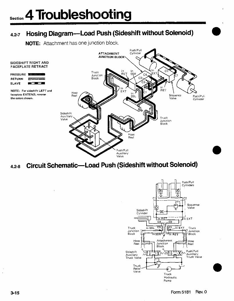
Section 4 Troubleshooting 4.2-7 Hosing Diagram- Load Push (Sideshift without Solenoid)
NOTE: Attachment has one junction block.
ATTACHMENT .___-__
StDESHlFT RIGHT AND FACEPLATERETRACT
PRESSURE
RETURN --- a. ..i.iiii:, :..:._.:.: :,: _, ..i
JUNCTION BLOCK
Truck Junction Block
SLAVE -
NOTE: For sideshift LEFT and
faceplate EXTEND, reverse
the colors shown.
4.2-8 Circuit Schematic-Load Push (Sideshift without Solenoid)
Sequence Valve
Push/Pull Cylinder
-Hose Reel
Auxiliary
Truck Junction Block
I
A
Truck Truck Hydraulic Hydraulic Pump Pump
Sideshift Auxiliary Truck Valve
Push/Pull Auxiliary Truck Valve
Truck Relief Valve
3-15 Form 5181 Rev. 0
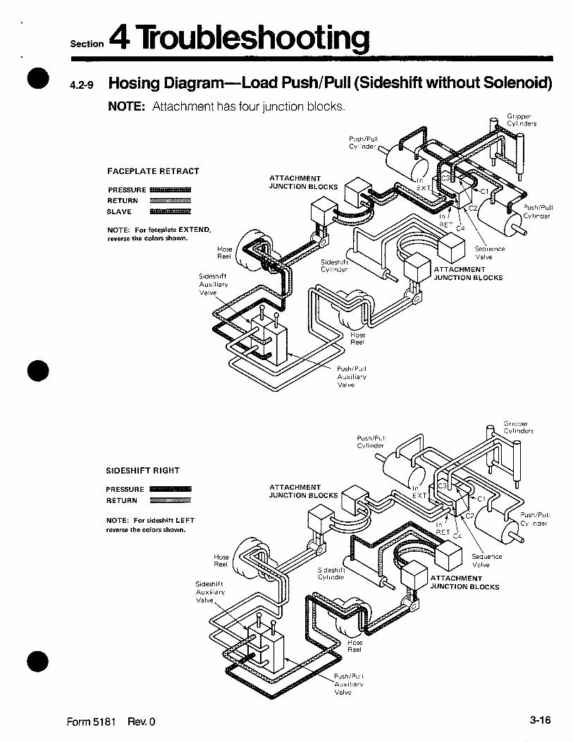
Section 4 Troubleshooting Hosing Diagram -Load Push/Pull (Sideshift without Solenoid)
NOTE: Attachment has four iunction blocks.
4.2-9
> - Gr~ooer
Push/Pul Cy I inder
FACEPLATERETRACT
PRESSURE
RETURN m
SLAVE
NOTE: For faceplate EXTEND, ,everse the colors shown.
ATTACHMENT JUNCTION BLOCKS
rc:
Sideshift Auxiliary I Valve JC
Push/Pull Cylinder
SIDESHIFT RIGHT
ATTACHMENT JUNCTION BLOCKS
Hose Reel
PRESSURE
RETURN * . . . ...>.. . . . . . . . . . . . . . . /i.,..., ~ . ..., .~~.:.:.,
ush/Pull
ylinder NOTE: For sideshift LEFT
reverse the colors shown.
Sideshift
Valve
Form 5181 Rev. 0 3-16

Section 4 Troubleshooting 4.2-l0 Hosing Diagram -Load Push/Pull (Sideshift without Solenoid)
NOTE: Attachment has one junction bl lock.
FACEPLATERETRACT
PRESSURE -
RETURN u ,.,.. :...:...:...:i.: :.:::: . . . .
SLAVE -
NOTE: For faceplate EXTEND,
reverse the colors shown.
SIDESHIFT RIGHT
PRESSURE -
RETURN
NOTE: For sideshift LEFT
reverse the colors shown.
ATTACHMENT JUNCTION BLOCK
Sideshift Auxilary Valve
Valve
n Gripper
Seque”ce -Push/Pull Valve Cylinder
Truck Junction. Block
ATTACHMENT JUNCTION BLOCK
Valve
Seqdence
Valve Push/Pull Cvlinder
3-17 Form 5181 Rev. 0

Section 4 Troubles hooting e 4.2-11 Circuit Schematic-Load Push/Pull
(Sideshift without Solenoid)
Gripper Cylinders
Sideshift Auxiiary Vah
Form 5181 Rev. 0
NOTE: s ome attachments have one attachment junction block and use truck lunction blocks.
3-1 a

Section 4 Troubleshooting 4.2-12 Hosing Diagram- Load Push (Sideshift with Solenoid) l
FACEPLATERETRACT
PRESSURE
RETURN . . . . . . . . . ..._...” . .._..... :r.: _.. . .,.
SLAVE ip81
NOTE: For faceplate EXTEND,
reverse the colors shown.
Truck Auxiliary Valve
SIDESHIFT RIGHT
PRESSURE
R ET U R N iiiii’ii=iiii:i^i:i:=:::.:~ :==i
NOTE: For sideshift LEFT,
reverse the colors shown.
Truck Auxiliary Valve
In EXT- gj
Solenoid Valve
In EXT
Solenoid Valve
/Pull lder
‘ush/Pull Minder
3-19 Form 5181 Rev. 0
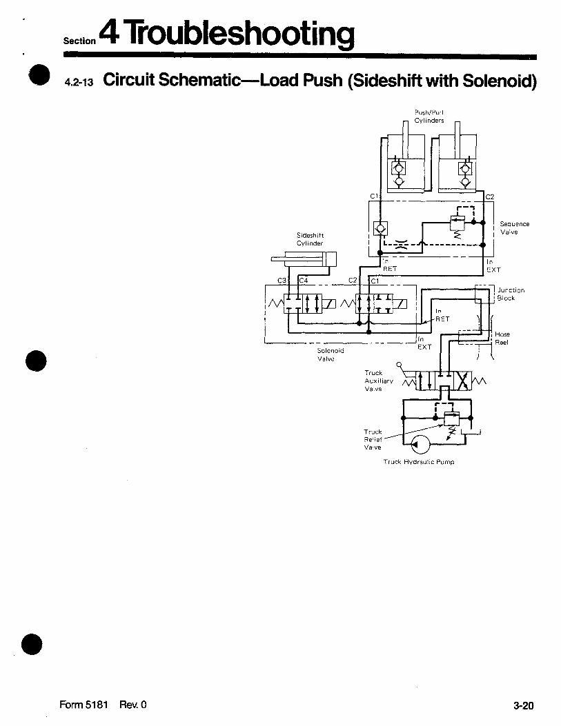
Section 4 Troubleshooting 4.2-13 Circuit Schematic-Load Push (Sideshift with Solenoid)
Push/Pull
Sideshift Cylinder
r I
II I
Sequence Valve
Solenoid Valve
Truck Hydraulic Pump
Form 5181 Rev.0 3-20

Section 4 Troubleshooting 4.2-14 Hosing Diagram- Load Push/Pull (Sideshift with Solenoid)
FACEPLATE RETRACT
PRESSURE
RETURN 33=--=+ . .,,. .:.:
SLAVE -
NOTE: For faceplate EXTEND, revem the colors shown.
Truck Auxiliary Valve
SIDESHIFT RIGHT
PRESSURE IO
RETURN /m
NOTE: For sidashift LEFT
reverse the colors shown.
Truck Auxiliary Valve
EXT
Solenoid Valve
Sideshift Cylinder fi\
Ish/Pull ‘limier
3-21 Form 5181 Rev. 0
.
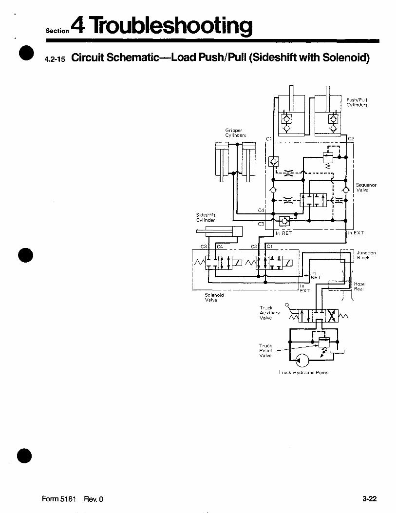
Section 4 Troubleshooting . l 4.2-15 Circuit Schematic-Load Push/Pull (Sideshift with Solenoid)
Gripper Cyilnders
Sideshift Cylinder
Sequence Valve
1 In EXT
Solenoid Valve
Truck Auxiliary Valve
I I
Truck Relief Valve
w Truck Hydraulic Pomp
Form 5181 Rev. 0 3-22
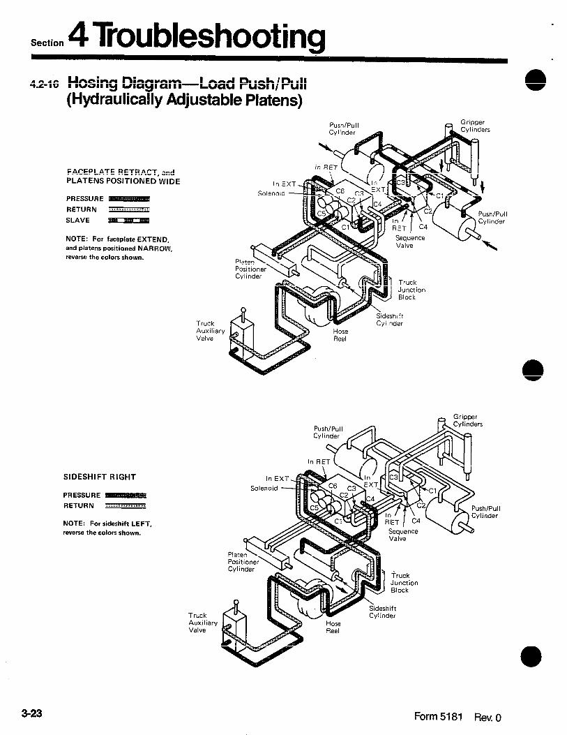
Section 4 Troubleshooting 4.2-16 Hosing Diagram-Load Push/Pull
(Hydraulically Adjustable Platens)
FACEPLATE RETRACT, and PLATENS POSJTIONED WIDE
PRESSURE
RETURN ./ ,,..:: :. ..,; : ,,:
SLAVE
NOTE: For faceplate EXTEND,
and platens positioned NARROW,
reverse the colors shown.
Push/Pull
Truck Auxiliary Valve
SIDESHIFT RIGHT
PRESSURE
RETURN ..: .: i..: : :.::,: : : : :.:. :::
NOTE: For sideshift LEFT,
reverse the colors shown.
Truck Auxiliary Valve
Cvlinder p \
_ Grimer
Sequence Valve
inders
iruck Junction Block
eideshift r Cylinder
3-23 Form 5181 Rev, 0
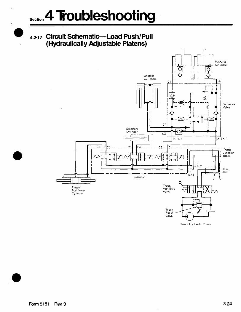
Section 4 Troubleshooting 0 4.2-17 Circuit Schematic-Load Push/Pull
(Hydraulically Adjustable Platens)
Gripper Cylinders
Sideshift Cylinder
7-k 37 ;
--‘r’, - ------ ‘) I I Con, ,O”r..
In EXT
Solenoid
Platen Positioner Cylinder
1 r-1 I
r--+-f , Hose Reel
Truck Hydraulic Pump
Form 5181 Rev. 0 3-24

Section 4 Troubleshooting L 4.-18 Hosing Diagram-Load Push/Pull
(Sheet Retainer-Sheet Sav®)
FACEPLATE RETRACT
PRESSURE
RETURN L ’ = .::?:::::::.:..:A. ...,..... :i
SLAVE -
Note: For faceplate EXTEND,
reverse the colors shown. In A EXT
Sideshift
Truck Auxiliary Valve
SIDESHIFT RIGHT
PRESSURE -
RETURN iiiiiii.i:..i_::li: .:,:::,:,:,::::,: :.
NOTE: For faceplate EXl
reverse the colors shown.
Truck Auxilia Valve
Push/Pul
Cylinder
Solenoid
/ Valve
Sequence Valve
In In
Sheet Retainer
Junction Rlock
Gripper Cylinder
Solenoid / Valve
In In \ \\\\
Sheet Retainer
Junction Block
Gripper Cylinder
Push/Pull Cylinder
3-25 Form 5181 Rev. 1
.
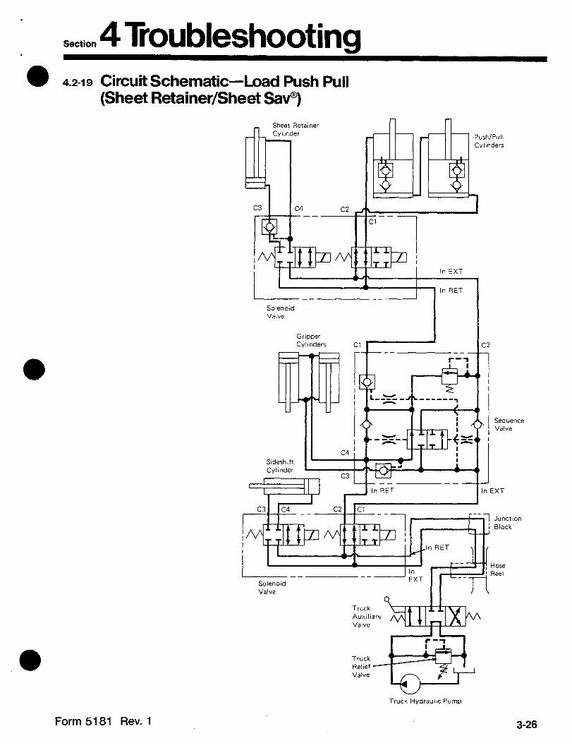
Section 4 Troubleshooting 0 4.2-19 Circuit Schematic-Load Push Pull
(Sheet Retainer/Sheet Sav®)
Sheet Retainer
( ‘1, In RET I--
Solenoid Valve
Gripper Cylinders Cl
I I c4 ,
Sideshift Cylinder r.e
I Sequence Valve
In EXT
Valve
Truck Auxiliary Valve
Truck Relief Valve
r-1 I
+i?@
Truck Hydraulvz Pump
Form 5181 Rev. 1 3-26
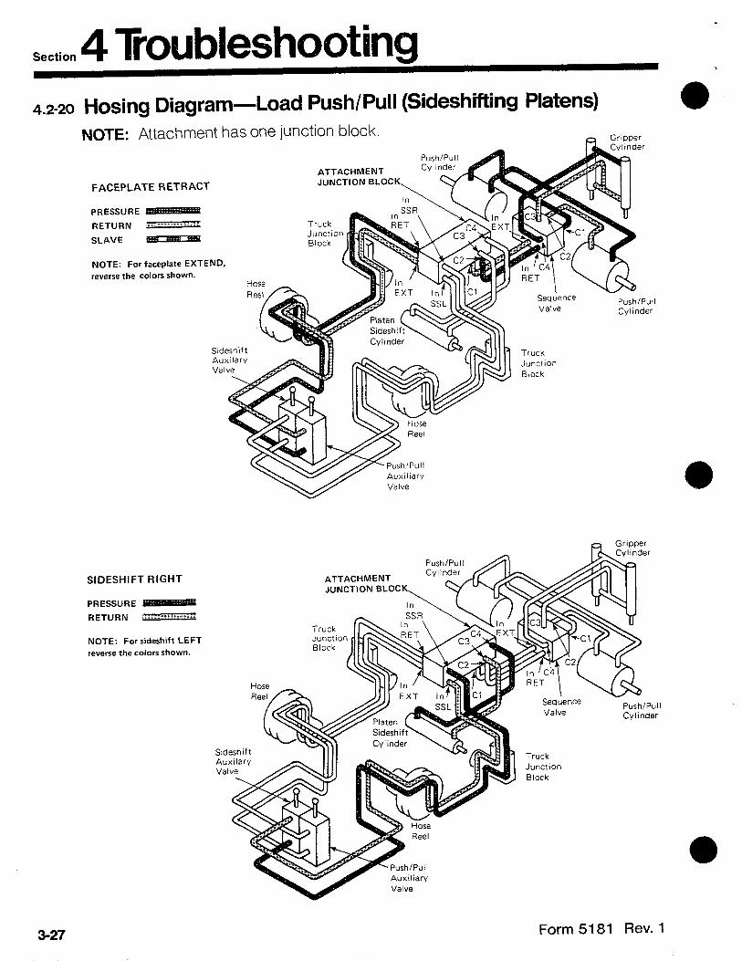
Section 4 Troubleshooting 4.2-20 Hosing Diagram- Load Push/Pull (Sideshifting Platens)
NOTE: Attachment has one junction block.
FACEPLATE RETRACT
PRESSURE RETURN :: ,.... :. :.:: :,:: .:.
SLAVE
NOTE: For faceplate EXTEND,
reverse the colors shown.
SIDESHIFT RIGHT
PRESSURE RET” R N .?!!%Y:i’i .j;j :: : 2 .:/
NOTE: For sideshift LEFl
reverse the colors shown.
Grtpper
ATTACHMENT JUNCTION BLOCK
ATTACHMENT JUNCTION BLOCK
3-27 Form 5181 Rev. 1

.
Section 4 Troubleshooting 4.2-21 Circuit Schematic-Load
(Sideshifting Platens) Push/Pull
Gripper Cvllnders
Push/Pull Cy I I nders
^^ Cl LL
-- --
Sequence Valve
Truck Relief Valve
Truck Hydraulic Pump
#NOTE. Some attachments have one attachment lunction block and use truck junction blocks.
Form 5181 Rev. 1 3-28
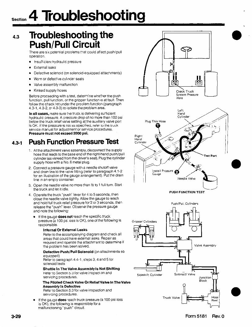
Section 4 Troubles hooting 4.3 Troubleshooting the
Push/Pull Circuit There are six potential problems that could affect push/pull operation.
l InsuffIcient hydraulic pressure
l External leaks
l Defective solenoid (on solenoid-equipped attachments)
l Worn or defective cylinder seals
l Valve assembly malfunction
l Kinked supply hoses
Before proceeding with a test, determine whether the push function, pull function, or the gripper function is at fault. Then follow the check list under the problem function (paragraph 4.3-1, 4.3-2, or 4.3-3) to isolate the problem area.
In all cases, make sure the truck is delivering sufficient hydraulic pressure. A pressure drop of no more than 100 psi below the truck relief valve setting at the auxiliary valve port is OK. If the pressure is not as specified, refer to the truck service manual for adjustment or service procedures. Pressure must not exceed 2000 psi.
4.3-1 Push Function Pressure Test 1. At the attachment valve assembly, disconnect the supply
hose that leads to the base end of the right-hand push/pull cylinder (as viewed from the driver’s seat). Plug the cylinder supply hose with a No. 6 metal plug.
2. Connect a pressure gauge with a needle shutoff valve and drain line to the valve fitting (refer to paragraph 4.1-2 for an illustration of the gauge arrangement). Put the drain line in an empty container.
3. Open the needle valve no more than ½ to 1 full turn. Start the truck and let it idle.
4. Operate the truck “push” lever for 4 to 5 seconds, then close the needle valve tightly. Allow the gauge to reach and hold full truck relief pressure for 2 or 3 seconds, then release the ”push” lever. Observe the pressure gauge and note the following:
l If the gauge does not reach the specific tiuck pressure (a 100 psi loss is OK), one of the following is responsible.
Gripper Cylinders
Internal Or External Leaks Refer to the accompanying diagram and check all areas that could have external leaks. Repair as required and operate the attachment to determine if the problem has been solved.
Defective Push/Pull Solenoid (on attachments so equipped) Refer to paragraph 4.4-1, steps 3, 4 and 5 for solenoid tests.
Shuttle In The Valve Assembly Is Not Shifting Refer to Section 5.3 for valve inspection and servicing procedures.
The Piloted Check Valve Or Relief Valve In The Valve Assembly Is Defective Refer to Section 5.3 for valve inspection and servicing procedures.
l If the gauge does reach truck pressure (a 100 psi loss is 0K);the following is responsible for a malfunctioning “push” circuit.
Check Truck System Pressure Here
PUSH FUNCTION TEST
Push/Pull Cylinders
Assembly
Junction I I Block
3-29 Form 5181 Rev. 0

l
Section ‘ 4 Troubleshooting a
0
Push/Pull Cylinder Is Defective When the faceplate extends unevenly with the right side out farther than the left, suspect the left-hand cylinder: vice versa for the right-hand cylinder. To further check the cylinders, install a drain line to the base end port and apply pressure to retract the cylinder. A steady oil stream after full retraction indicates a bypass of oil at the seals or compensator valve. Refer to Section 5.4 for cylinder inspection and servicing procedures.
4.3-2 Pull Function Pressure Test 1. At the valve assembly, disconnect the supply hose that
leads to the rod end of the left-hand push/pull cylinder (as viewed from the driver’s seat). Plug the cylinder supply hose with a No. 6 metal plug.
2. Connect a pressure gauge with a needle shutoff valve and drain line to the valve fitting (refer to paragraph 4.1-2 for an illustration of the gauge arrangement). Put the drain line in an empty container.
3. Open the needle valve no more than l/z to 1 full turn. Start the truck and let it idle.
4. Operate the truck “pull” lever for 4 to 5 seconds, then close the needle valve tightly. Allow the gauge to reach and hold full truck relief pressure for 2 or 3 seconds, then release the “pull” lever. Observe the pressure gauge and note the following:
l If the gauge does not reach the specific truck pressure (a 100 psi loss is OK), one of the following IS responsible.
Internal Or External Leaks Refer to the accompanying diagram and check all areas that could have external leaks. Repair as required and operate the attachment to determine if the problem has been solved.
Defective Push/Pull Solenoid (on attachments so equipped) Refer to paragraph 4.4-1, steps 3, 4 and 5 for solenoid tests.
Shuttle in The Valve Assembly Is Not Shifting Refer to Section 5.3 for valve inspection and servicing procedures.
The Piloted Check Valve Or Relief Valve In The Valve Assembly Is Defective Refer to Section 5.3 for valve inspection and servicing procedures.
l If the gauge does reach truck pressure (a 100 psi loss is OK), the following is responsible for a malfunctioning ” pull ” circuit,
Push/Pull Cylinder Is Defective When the faceplate extends unevenly with the right side out farther than the left, suspect the left-hand cylinder; vice versa for the right-hand cylrnder. To further check the cylinders, install a drain line to the base end port and apply pressure to retract the cylinder. A steady oil stream after full retraction indicates a bypass of oil at the seals or compensator valve. Refer to Section 5.4 for cylinder inspection and servicing procedures.
Suspect Left Cylinder
/ Right Side extends farther
PULL FUNCTION TEST
I \ Suspect Left Cylinder /
\ I Right Side extends farther
Form 5181 Rev.1 3-30

4 Troubleshooting .
Section
,
4.3-3 Gripper Function If the gripper bar is not functioning properly, one of the following is responsible.
WARNING: Disconnect Push/Pull cylinder rod and pins (see diagram 5.4-l) from A pantograph arm prior to testing to avoid possible in advertant faceplate retraction.
The Gripper Bar Is Mechanically Jammed Inspect for bent or broken hardware and replace where necessary.
Kinked Supply Hose Check the hoses from the valve to the cylinders for any kinks. Replace hoses if either is kinked.
Worn Cylinders Seals Extend the faceplate. Disconnect the hose at the left hand push/pull cylinder rod end. Plug or cap the open ports and hoses.
Install a drain line on the rod ends of the gripper cylinders and apply pressure to extend the cylinders. A steady stream of oil, after full extension, indicates a bypass at the seals. Refer to Section 5.4 for cylinder inspection and servicing procedures.
Piloted Check Valve In The Valve Assembly Is Defective Remove the gripper function tubing at the valve and replace with the pressure gauge and drain hose assembly. Apply pressure to extend the gripper cylinders.
gauge and drain
l If the gauge does not regrster a pressure reading, remove and replace the gripper check valve. See Drain hose paragraph 5.3-2 for service procedures
l If the gauge registers a low pressure reading, check for kinked hoses.
Call Cascade’s Service Department If you have carefully and accurately completed this check list and you still have not solved to problem, call us. Our Service Department is open from 10:00 AM to 8:00 PM Eastern time.
Call 800-547-5266 (toll free) In Oregon, 666-1511
3-31 Form 5181 Rev. 1
(For locations outside the U.S., contact your local Cascade branch.)

Section 4 Troubleshooting . Q 4.4 Troubleshooting the 7.5 Amp
Fuse
Sideshift Circuit There are four potential problem areas that could affect sideshift operations.
l Insufficient truck hydraulic pressure
l Damaged sideshift bearing strips and segments
l Defective solenoid (on solenoid-equipped attachments)
l Worn or defective cylinders seals
To isolate the problem area, complete the check list in the following sequence.
7.5 Amp
Remanning wires 1 are black /
4.4-1 Sideshift Troubleshooting Check List 1. To check for low hydraulic pressure delivered by the truck
Wiring 1*1, ma”
hydraulic system to the attachment install the pressure gauge in either line leading to the sideshift cylinder. TWO-FUNCTION
Operate the control handle. lOnebutton control knob}
l A pressure drop of no more than 100 psi below the truck relief valve setting at the auxiliary valve port is OK. If the pressure is not as specified, refer to the truck service manual for adjustment or service procedures.
~~~~mn
Pressure must not exceed 2000 psi.
l If the gauge does not register pressure or the push/pull circuit functions instead of the sideshift, perform the following tests: /“\ m Solenoid
2. On solenoid-equipped attachments, check for loose connections in all electrical wiring (from the control button, to the truck’s ignition switch, to the solenoid).
3. To test for voltage at the solenoid disconnect the electrical leads at the solenoid. Then, using a voltmeter or a test light, make sure there is voltage at the leads when the sideshift button is depressed.
l If there is no voltage to the solenoid, begin troubleshooting the electrical circuit for shorts (be sure to include the sideshift switch in the control handle in 7.5 Amp P
Q Control Knob
Red \
your tests).
l If there is voltage to the solenoid when the sideshift button is depressed, test for coil continuity. +
4. To test for coil continuity, check the solenoid coil by placing an ohmmeter test lead on each solenoid terminal
l If there is current through the ohmmeter, but the solenoid does not “click” when the sideshift button is depressed, the solenoid spool is jammed and the solenoid valve should be replaced.
l If there is no current through the ohmmeter, the coil is defective and should be replaced.
5. Inspect the sideshift bearing strips and segments for excessive wear. Replace if necessary. Keep the bearing strips and segments well lubricated with Dubois FGG-2 food industry grease, Cascade part no. C-669306.
6. The sideshift cylinder seals may be worn. Install a drain line in the base end of the cylinder and apply pressure to retract the cylinder. A steady stream of oil after full retraction indicates a bypass at the seals. Refer to Section.514 for cylinder inspection and servicing procedures.
k- Green (ground)
>
(ground)
Owner-supplied Wiring
THREE-FUNCTION (Two-button control knob)
Call Cascade’s Service Department If you have carefully and accurately completed this check list and you still have not solved the problem, call us. Our Service Department is open from 10:00 AM to 8:00 PM Eastern time.
Call 80&547-5266 (toll free) In Oregon, 666-l 51 I
(For locations outside the US., contact your local Cascade branch.) 3-32 Form 5181 Rev. 1

Section 4 Troubleshooting 4.5 Troubleshooting the
Hydraulically 7.5 Amp Fuse
Adjustable Platen Circuit There are three potential problem areas that could affect the adjustable platen operations.
l Insufficient truck hydraulic pressure
l Defective solenoid
l Worn or defective cylinder seals
To isolate the problem area, complete the check list in the following sequence.
4.5-1 Adjustable Platen Troubleshooting Check List 1. To check for low hydraulic pressure delivered by the truck
hydraulic system to the attachment install the pressure gauge in either line leading to the adjustable platen cylinder. Operate the control handle.
l A pressure drop of no more than 100 psi below the truck relref valve setting at the auxiliary valve port is OK. If the pressure is not as specified, refer to the truck service manual for adjustment or service procedures. Pressure must not exceed 2000 psi.
l If the gauge does not register pressure or the push/pull circuit functions instead of the adjustable platens, perform the following tests:
2. Check for loose connections in all electrical wiring (from the control button, to the truck’s ignition switch, to the solenoid).
3. To test for voltage at the solenoid disconnect the electrical leads at the solenoid. Then, using a voltmeter or a test light, make sure there is voltage at the leads when the adjustable platen button is depressed.
l If there is no voltage to the solenoid, begin troubleshooting the electrical circuit for shorts (be sure to include the adjustable platen switch in the control handle in your tests).
l If there is voltage to the solenoid when the adjustable platen button is depressed, test for coil continuity.
4. To test for coil continuity, check the solenoid coil by placing an ohmmeter test lead on each solenoid terminal.
l If there is current through the ohmmeter, but the solenoid does not “click” when the adjustable platen button is depressed, the solenoid spool is jammed and the solenoid valve should be replaced.
l If there is no current through the ohmmeter, the coil is defective and should be replaced.
5. The adjustable platen cylinder seals may be worn. Extend the faceplate. Disconnect the hose at the left hand push/pull cylinder rod end. Plug or cap the open ports and hoses. Install a drain line as shown in the illustration and apply pressure to extend the cylinder. A steady stream of oil after full extension indicates a bypass at the seals. Refer to Section 5.4 for cylinder inspection and servicing procedures.
3-33
Owner-supplied Wiring
THREE-FUNCTION (Two-button control knob)
I VIEWED FROM FRONT OF ATTACHMENT
Call Cascade’s Service Department If the problems listed in this Section do not correspond to the problem you have, or if the procedures outlined here have not solved your problem, do not proceed. Call a Cascade Service Representative at 800-547-5266 (toll-free), or in Oregon call 666-1511. Cascade’s Service Department is open between 10:00 AM and 8:00 PM Eastern time.
Call 800-547-5266 (toll free) In Oregon, 666-l511
(For locations outside the U.S., contact your local Cascade branch.)
Form 5181 Rev. 1
Section 4 Troubleshooting
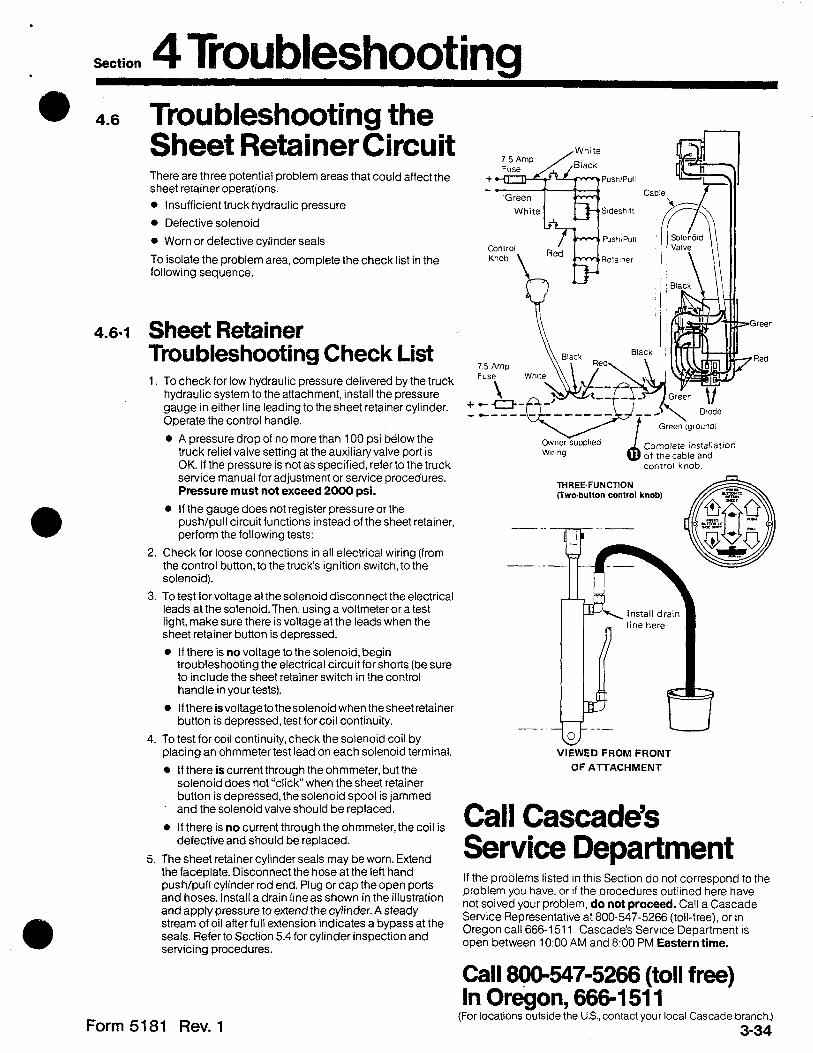
4.6-1 Sheet Retainer Troubleshooting Check List 1. To check for low hydraulic pressure delivered by the truck
hydraulic system to the attachment, install the pressure gauge in either line leading to the sheet retainer cylinder. Operate the control handle.
A pressure drop of no more than 100 psi below the truck relief valve setting at the auxiliary valve port is OK. If the pressure is not as specified, refer to the truck service manual for adjustment or service procedures. Pressure must not exceed 2000 psi.
If the gauge does not register pressure or the push/pull circuit functions instead of the sheet retainer, perform the following tests:
Check for loose connections in all electrical wiring (from the control button, to the trucks ignition switch, to the solenoid).
To test for voltage at the solenoid disconnect the electrical leads at the solenoid. Then, using a voltmeter or a test light, make sure there is voltage at the leads when the sheet retainer button is depressed.
l If there is no voltage to the solenoid, begin troubleshooting the electrical circuit for shorts (be sure to include the sheet retainer switch in the control handle in yourtests).
0 If there is voltage to thesolenoid when the sheet retainer button is depressed, test for coil continuity.
To test for coil continuity, check the solenoid coil by placing an ohmmeter test lead on each solenoid terminal.
0 If there is current through the ohmmeter, but the solenoid does not “click” when the sheet retainer button is depressed, the solenoid spool is jammed and the solenoid valve should be replaced.
0 If there is no current through the ohmmeter, the coil is defective and should be replaced.
The sheet retainer cylinder seals may be worn. Extend the faceplate. Disconnect the hose at the left hand push/pull cylinder rod end. Plug or cap the open ports and hoses. Install a drain line as shown in the illustration and apply pressure to extend the cylinder. A steady stream of oil afterfull extension indicates a bypass at the seals. Refer to Section 5.4 for cylinder inspection and servicing procedures.
4.6 Troubleshooting the Sheet Retainer Circuit There are three potential problem areas that could affect the sheet retainer operations.
0 Insufficient truck hydraulic pressure
0 Defective solenoid
0 Worn or defective cylinder seals
To isolate the problem area, complete the check list in the following sequence.
d control knob.
Complete installation of the cable and
Form 5181 Rev. 1
z-Green
7 Red
- _. 33 --- 0
VIEWED FROM FRONT
OF ATTACHMENT
Call Cascade’s Service Department If the problems listed in this Section do not correspond to the problem you have, or if the procedures outlined here have not solved your problem, do not proceed. Call a Cascade Service Representative at 800-547-5266 (toll-free), or in Oregon call 666-1511. Cascade’s Service Department IS open between 10:00 AM and 8:00 PM Eastern time.
Call 800-547-5266 (toil free) In Oregon, 666-1511
(For locations outside the U.S., contact your local Cascade branch.)
3-34
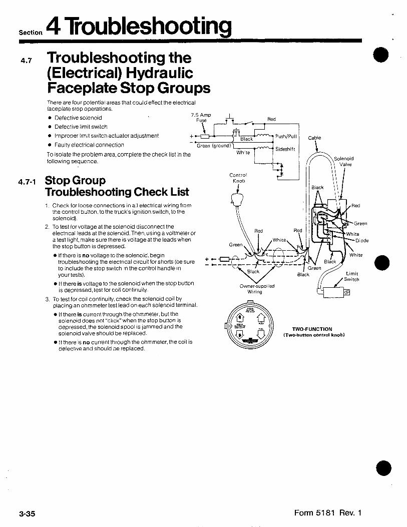
Section 4 Troubleshooting 4.7
4.7-1
Troubleshooting the (Electrical) Hydraulic Faceplate Stop Groups There are four potential areas that could effect the electrical faceplate stop operations.
l Defective solenoid 7.5 Amp
Fuse -L Red
l Defective limit switch
a Improper ltmit switch actuator adjustment
0 Faulty electrical connection
+ A 1 T y+ “rj,,
] Black Push/Pull
Green (ground1 1 4)
White -, Sideshift
To isolate the problem area, complete the check list in the following sequence.
Knob - Control
Stop Group Troubleshooting Check List 1. Check for loose connections in all electrical wiring from
the control button, to the trucks ignition switch, to the solenoid).
2. To test for voltage at the solenoid disconnect the electrical leads at the solenoid. Then, using a voltmeter or a test light, make sure there is voltage at the leads when the stop button IS depressed.
0 If there is no voltage to the solenoid, begin troubleshooting the electrical circuit for shorts (be sure to include the stop switch in the control handle in your tests).
l If there is voltage to the solenoid when the stop button is depressed, test for coil continuity.
3. To test for coil continuity. check the solenoid coil by placing an ohmmeter test lead on each solenoid terminal.
l If there is current through the ohmmeter, but the solenoid does not “click” when the stop button is depressed, the solenoid spool is jammed and the solenoid valve should be replaced.
0 If there is no current through the ohmmeter, the coil is defective and should be replaced.
Cable
Owner-&plied Wiring
TWO-FUNCTION (Two-button control knob)
3-35 Form 5181 Rev. 1

”
Section 4 Troubleshooting . 4.7-1 Stop Group
Troubleshooting Check List (Cont.) +
4. To test for voltage at the limit switch disconnect the leads at the switch. Then using a voltmeter or a test light, make sure there is voltage at the leads when the stop button on the control knob is pressed.
l If there is no voltage at the limit switch, begin trouble- shooting the electrical circuit for shorts (be sure to include the stop switch in the control handle in your tests).
l If there is voltage to the limit switch when the stop button is depressed, test for coil continuity.
5. To test for limit switch continuity, check the switch by placing an ohmmeter test lead on each limit switch lead
l If there is no current through the limit switch and the actuator wire is rotated to activate the switch, the limit switch is defective and should be replaced.
.o
7.5 Amp Fuse
Cable
Solenoid
Owner-supplied Wfrinb ?
Limit Switch
THREE-FUNCTION
(Three-button control knob)
Call Cascade’s Service Department If you have carefully and accurately completed this check list and you still have not solved to problem, call us. Our Servrce Department is open from 10:00 AM to 8:00 PM Eastern time.
Call 800-547-5266 (toll free) In Oregon, 666-1511 (For locatrons outsrde the U.S., contact your local Cascade branch.)
Form 5181 Rev. 1 3-36

Section 5 Service 5.1 Attachment Removal
and Installation Fully extend the faceplate.
Lower the attachment onto a pallet
Remove the lower mounting hooks. For reassembly tighten the capscrews to a torque of 105-115 ft.-lbs.
Quick Disconnect Hooks: Pull the pin as far as it will go, rotate the hooks down and reinstall pin as shown.
Disconnect, tag, and cap the attachment hoses at the truck junction block(s).
NOTE: Some units will have truck hoses attached to junction blocks on the attachment. Disconnect and cap these.
Disconnect the sideshift cylinder, if equipped, from the truck carriage anchor bracket.
Disconnect the electrical connection at the truck, on solenoid mounted attachments.
Lower the truck carriage and back away from the attachment.
Quick Disconnect Units: Tilt the mast fully forward before lowering the carriage and backing away from the attachment.
For reinstallation, reverse the above procedures, making sure tab in upper hook properly engages notch in upper truck carriage bar.
Fully Extend the Faceolate
6 Lower Attachment
b Remove Lower Mounting Hooks
onto a Pallet
QUICK DISCONNECT UNITS
n Lower Carriage A II I--
3-37 Form 5181 Rev. 1

.o
5.2 Faceplate and Pantograph Arms
5.2-l Disassembly 0 Remove the cotter pin and pin from the link on the
backside of the faceplate.
@ Remove the cotter pin and castellated nut that join the secondary arms together. Remove the pin.
0 Disconnect the four gripper hose ends from the tubing on the top primary arm. Disconnect the gripper hose ends from the gripper cylinder fittings. Cap the hose ends and tag for reassembly.
0 Attach a hoist chain to the faceplate.
0 Remove the capscrews and pins which hold the secondary arms to the primary arms.
0 Twist each secondary arm towards the faceplate center to remove them from the channels on the backside of the faceplate.
@ Attach a hoist to the frame assembly if the attachment was removed from the truck.
0 Remove the capscrews and pins from the rod end of the push/pull cylinders.
0 Remove the frame capscrews and pins that hold the pantograph arms to the frame.
Section 5 Service 1
nemove ‘ and Dins
Attach a hoist chain if attachment was removed from truck
Top Primary Arm Tubing
Remove capscrews and pins
Remove cotter pin
Attach hoist chain
Secondary Arm
Twist each arm toward center
Remove cotter pin and pin from link
Form 5181 Rev. 2 3-38
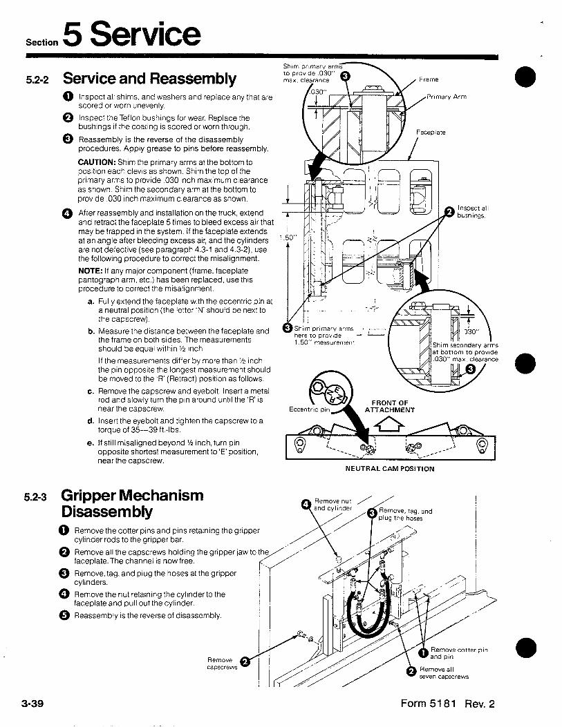
Section 5 Service 5.2-2 Service and Reassembly
0 Inspect all shims, and washers and replace any that are scored or worn unevenly.
0 Inspect the Teflon bushings for wear. Replace the bushings if the coating is scored or worn through.
0 Reassembly is the reverse of the disassembly procedures. Apply grease to pins before reassembly.
CAUTION: Shim the primary arms at the bottom to position each clevis as shown. Shim the top of the primary arms to provide ,030 inch maximum clearance as shown. Shim the secondary arm at the bottom to provide ,030 inch maximum clearance as shown.
0 After reassembly and installation on the truck, extend and retract the faceplate 5 times to bleed excess air that may be trapped in the system. If the faceplate extends at an angle after bleeding excess air, and the cylinders are not defective (see paragraph 4.3-l and 4.3-Z). use the following procedure to correct the misalignment.
NOTE: If any major component (frame, faceplate pantograph arm, etc.) has been replaced, use this procedure to correct the misalignment.
a. Fully extend the faceplate with the eccentric pin at a neutral positron (the letter ‘N’ should be next to the capscrew).
b. Measure the distance between the faceplate and the frame on both sides. The measurements should be equal within % inch.
If the measurements differ by more than % inch the pin opposite the longest measurement should be moved to the ‘R’ (Retract) positron as follows.
c. Remove the capscrew and eyebolt. Insert a metal rod and slowly turn the pm around until the ‘R’ is near the capscrew.
cl. Insert the eyebolt and tighten the capscrew to a torque of 35-39 ft.-lbs.
e. If still misaligned beyond % inch, turn pin opposite shortest measurement to ‘E’ position, near the capscrew.
5.2-3 Gripper Mechanism Disassembly
0 Remove the cotter pins and pins retaining the gripper cylinder rods to the gripper bar.
‘y Arm
Ghim primary arms 1 ci=-~=
here ‘IO provide L L.
1.50” measurement k II
Shim sect Dndary arms at botrom to provide
FRONT OF ATTACHMENT
NEUTRAL CAM POSITION
0 Remove all the capscrews holding the gripper jaw to faceplate.The channel is now free.
0 Remove, tag, and plug the hoses at the gripper cylinders.
0 Remove the nut retaining the cylinderto the faceplate and pull out the cylinder.
0 Reassembly is the reverse of disassembly.
Remove cottwpin
3-39 Form 5181 Rev. 2
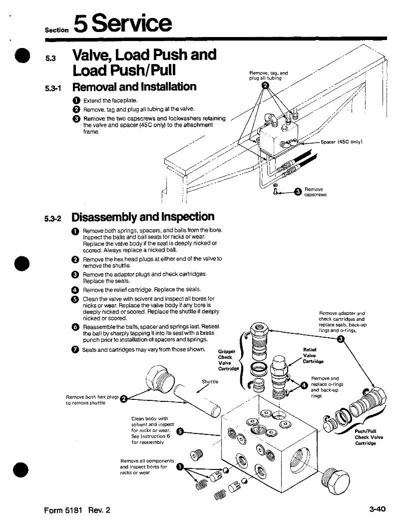
Section 5 Service a 5.3 Valve, Load Push and
Load Push/Pull 5.3-1 Removal and Installation
@ Extend the faceplate.
@ Remove, tag and plug all tubing at the valve.
0 Remove the two capscrews and lockwashers retaining the valve and spacer (45C only) to the attachment frame.
Spacer (45C only)
5.3-2 Disassembly and Inspection 0 Remove both springs, spacers, and balls from the bore.
Inspect the balls and ball seats for nicks or wear. Replace the valve body if the seat is deeply nicked or scored. Always replace a nicked bail.
@ Remove the hex head plugs at either end of the valve to remove the shuttle.
@ Remove the adaptor plugs and check cartridges. Replace the seals.
0 Remove the relief cartridge. Replace the Seals.
0 Clean the valve with solvent and inspect all bores for nicks or wear. Replace the valve body if any bore is deeply nicked or scored. Replace the shuttle if deeply Remove adapter and nicked or scored. check cartridges and
0 Reassemble the balls, spacer and springs last. Reseat replace seals, back-up
the ball by sharply tapping it into its seat with a brass iings and o-rings.
punch prior to installation of spacers and springs.
@ Seals and cartridges may vary from those shown.
Remove both hex plugs to remove shuttle
Clean body with solvent and inspect for nicks or wear. See Instruction 6 for reassembly
Remove all components and inspect bores for nicks or wear
Form 5181 Rev. 2

Section 5 Service 5.4
5.4-l
5.4-2
Cylinders Gripper Cylinder Removal and Installation 0 See steps 2,4, and 5 in paragraph 5.2-3 to remove the
cylinder.
0 Reverse the procedures to install the cylinder.
Push/Pull Cylinder Removal and Installation 0 Remove, tag and plug the hoses at the push/pull
cylinder.
0 Remove the Capscrews and pins retaining the rod ends.
NOTE: The cylinder may be swung out and serviced at this time.To cbmpletely remove the cylinder proceed.
0 Remove the capscrews, eyebolt and pin holding the cylinder to the frame. (Note position of eccentric pin for reassembly.)
0 Installation is a reverse of the above procedures.
5.4-3 Sideshift Cylinder Removal and Installation 0 Remove, tag and plug the hoses at the sideshift
cylinder.
0 Remove the cotter pins and pins at the rod and base ends and lift out the cylinder.
0 Installation is a reverse of the above procedures.
5.4-4 Sheet Retainer Cylinder Removal and Installation Q Use same steps as 5.4-3
0 For service see 5.4-9.
5.4-5 Adjustable Platen Cylinder Removal and Installation Remove the attachment from the truck according to the procedures in section 5.1. Extend the faceplate before removal.
@ Remove and plug the tubes at the cylinder.
@ Remove the cotter pins and pins at both ends of the cylmder.
@ Remove the capscrews retaining the cylinder to the frame and lift out the cylinder.
0 Installation is a reverse of removal.
A WARNING: Remove push/pull rod end pins to avoid possible injury due to inadvertant faceplate retraction.
Remove Capscrew.
Remove, tag, and
Remove cotter pin and pin
Remove Cotter Pins and Pins
Remove Capscrews
[For Reassemblv: I
3-41
prw~~~ppcrews to 1
Form 5181 Rev. 1

Section 5 Service l
l 5.4-6 General Cylinder Service Procedures Cylinder Disassembly
Use a pin type spanner wrench to remove push/pull Load Push/Pull Cvlindm
cylinder retainer.
When servicing a cylinder, clamp it in a soft-jawed vise as shown. Never clamp the cylinder shell or the cylinder rod sealing area in a vise.
To remove the seal from a piston or a retainer, put the piston or retainer in a soft-jawed vise. Pry the seal up with a blunt tool such as a screwdriver, then cut the seal to remove it. Be careful not to scratch the seal groove.
Clamp cylinder in soft-jawed vise
Cylinder Inspection Inspect the rod, piston, and retainer for nicks or burrs. If deeply gouged, replace the part. Minor nicks and burrs can be removed with an emery cloth.
Sideshift and Gripper Cylinder
NOTE: A minor nick is one that will not cause a bypass of oil when the cylinder is operating.
Inspect the inside of the cylinder shell and remove any minor nicks and burrs (see Note, above) with a butterfly hone. Replace the cylinder shell if it is deeply gouged.
Clamp cylinder in soft-jawed vise
Cylinder Assembly Lubricate all new seals with STP before installing.
To install a new seal on a piston or retainer, hook one side of the seal in the groove and push it over the piston or retainer.
NOTE: Polishing the chamfer angle will allow the seal to slide into the groove much easier.
Carefully note the direction of U-cup seals. If they are installed backwards, the seals will not seal properly. Refer to the illustration of the cylinder you are servicing on pages 3-43 and 3-44.
Always reassemble the rod asembly by sliding the retainer on first, then the piston assembly. Install and torque the piston retaining nut before sliding the rod assembly back into the shell.
When reassembling a cylinder, always observe all torque values as shown in the appropriate illustration.
Do not scratch
Form 5181 Rev. 1 3-42
Install new seals as shown

Section 5 Service 5.4-7 Gripper Cylinder Service
5.4-8
Read the General Service Procedures, paragraph 5.4-6 before proceeding.
0 Remove the snap ring.
0 Remove the retainer ring by first tapping the retainer into shell bore. Then place a screw driver on one side of the ring and tap the screwdriver gently with a hammer. Take care not to gouge shell bore with screwdriver. The retainer ring should compress at the split and turn sideways as shown at right. Grasp the ring and pull it out.
0 Pull the rod assembly out of the shell.
0 Remove the nut securing the piston to the rod.
0 Slide the piston and retainer off the rod.
0 Remove and replace all seals.
@ Perform the inspection and reassembly procedures llsted tn paragraph 5.4-6.
Tap screwdriver
0 Replace all seals
i
Remove the nut I / Cw\ J
Push/Pull Cylinder Service Read the General Service Procedures, paragraph 5.4-6 before proceeding.
Remove piston and retainer Pull rod
assembly out
0 Use a pin type spanner wrench to remove the retainer.
0 Pull the rod assembly out of the shell.
0 Remove the nut securing the piston to the rod.
0 Slide the piston and retainer from the rod.
CAUTION: On units equipped with platens shorter than 48 Inches, split spacers and shims must be tnstalled in the push/pull cylinders. If your unit was factory ordered (with platens shorter than
48 inches) the spacers and shims are factory installed. If you are installing the shorter platens, the spacers and shims are supplied with the platens for field installation.
To Install the spacers and shims you need only remove the retainer and slip the shims and split spacers into place.
-1
0
Remove and replace / all seals incluc
Remove retainer with pin-type
compensator 1
1ut .
spanner wrench
pz&=-J
Torque the capscrews to 9 ft.-lbs. Reinstall the retainer.
0 Remove and replace all seals including the compensator valve seals.
0 Perform the inspection and reassembly procedures in paragraph 5.4-6.
3-43 Form 5181 Rev. 1
l
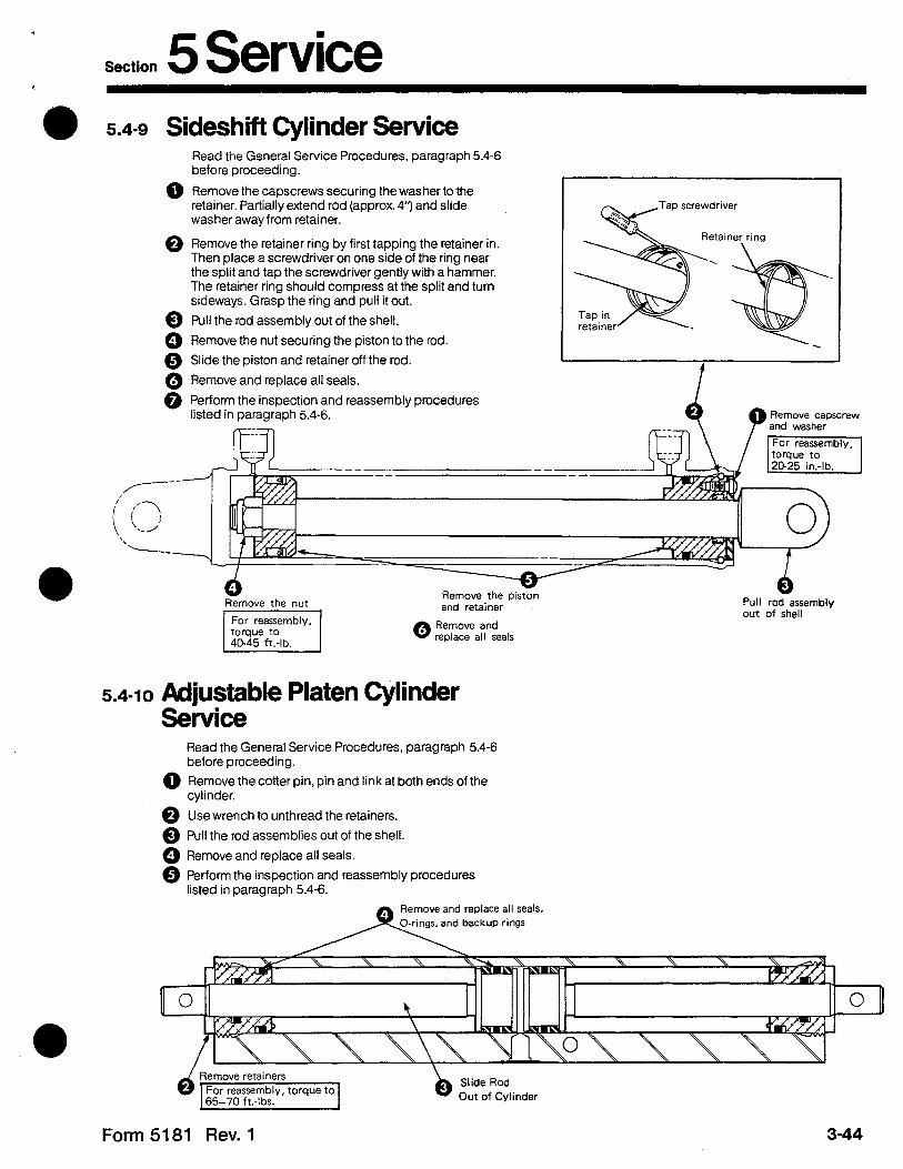
Section 5 Service 0 5.4-9 Sideshift Cylinder Service
@ Remove the capscrews securing the washer to the retainer. Partially extend rod (approx. 4”) and slide washer away from retainer.
0 Remove the retainer ring by first tapping the retainer in. Then place a screwdriver on one side of the ring near the split and tap the screwdriver gently with a hammer. The retainer ring should compress at the split and turn sideways. Grasp the ring and pull it out.
0 Pull the rod assembly out of the shell.
0 Remove the nut securing the piston to the rod.
0 Slide the piston and retainer off the rod.
0 Remove and replace all seals. -
@ Perform the inspection and reassembly procedures listed in paragraph 5.4-6.
Read the General Service Procedures, paragraph 5.4-6 before proceeding.
Tap screwdriver
Remove capscrew and washer
For reassemblv. 1
Remove the piston --.A __*_:-__
6 Pull rod assembly out of shell
Remove the nut
0 Remove and replace all seals
5.4-10 Adjustable Platen Cylinder Service
Read the General Service Procedures, paragraph 5.4-6 before proceeding.
@ Remove the cotter pin, pin and link at both ends of the cylinder.
0 Use wrench to unthread the retainers.
0 Pull the rod assemblies out of the shell.
@ Remove and replace all seals.
0 Perform the inspection and reassembly procedures listed in paragraph 5.4-6.
move and replace all seals,
nd backup rings
Form 5181 Rev. 1

Section 5 Service 5.5 Junction Blocks 5.5-1 Removal and Installation
., DESIGN 1
@ Design 1: Remove the capscrews retaining the junction block to the upper channel.
0 Design 1 and 2: Remove, tag, and plug the hoses or tubing at the junction blocks.
NOTE: You can remove the upper channel on design 1 at this time, but it is not necessary.
0 Design 1: Remove the capscrews retaining the junction blocks to the lower channel.
Design 2: Remove the capscrews retaining the junction block to the frame.
Q Installation is a reverse of removal.
Lower Channel
DESIGN 2
:? I
3 Remove capscrews
\. -_
!L’ ‘.-.\_ 8
\ , /.
3.*.
/’
) Remove. tag, and plug all hn<c.c nr ttthinn
3-45 Form 5181 Rev.1

Section 5 Service 5.6 solenoid valve
5.6-1 Removal and Installation Determine which version you have (as shown) and use that illustration for solenoid removal and installation as follows.
@ Remove the cover plate as shown.
0 Remove, tag and plug all hoses or tubes at the solenoid.
0 Disconnect all electrical leads at the solenoid.
NOTE: Mark each lead for ease in reinstallation.
0 Remove the capscrews retaining the solenoid to the frame.
0 Installation is a reverse of removal.
Remove Capscrews
rckh
Remove Cover Plate
! A
Disconnect and rag
, tag, and plug and tubing
Disconnect and tag all electrical leads
Remove
Disconnect and tag all electrical leads
Remove, tag, and plug all hoses and tubing
Remove, tag, and plug all hoses and tubing
Form 5181 Rev. 1 3-46

Section 5 Service
5.6-2 Service NOTE: Two function solenoid shown. Some units will have a three function solenoid. The procedures are the same.
0 Remove the nut.
0 Remove the coil. Replace if necessary.
CAUTION: Always replace the coil with a coil of the same voltage.
0 Remove the screw-in cartridge and replace the O-rings
@ Clean the hydraulic parts with solvent before reassembly. Blow dry with compressed air.
c
s
l .
Remove the cartridge and replace O-rings
Clean hydraulic parts with solvent and blow dry
3-47 Form 5181 Rev. 1

4
Section 5 Service . a 5.7 Platens (Original Design)
5.7-1 Removal and lnstallation, (with unit mounted on truck) CAUTION: If you are removing your 48 inch platens to install shorter platens, you must also install the spacers and shims (supplied with the platens) in the push/pull cylinders. See paragraph 5.4-8 for spacer installation procedures.
0 Platen tips must be even or within l/4” of each other. Add shims to raise platen tips. Remove shims to lower tips.
4 4
II
0 Extend the faceplate fully.
0 With the platens fiat on the floor remove the capscrews securing the hooks to the platens.
0 Remove the hook. Raise the truck carriage 3 in. then back the truck and attachment away from the platens.
0 To install, reverse the above procedures. t t
NOTE
WARNING
5.7-2
IA WARNING: Tighten platen capscrews to 200-210 ft.-lbs.
NOTE: When installing platens make sure both platen tips are even or within 1/4” of each other and that contact between the gripper jaw and the platens occurs when the faceplate is extended 24-30 inches from the frame. Add shims (between the plate and frame) to raise platen tips or remove shims to lower tips to meet these . requirements. requirements.
Inspection 0 Check the platen tips for nicks. Flatten out nicks with a
hammer and smooth the edges with a file or grinder.
@ An application of wax or paraffin on the top of the platens will reduce friction between the platens and slip sheets. Use a piece of steel wool to remove excess wax.
Inspection 0 Check the platen tips for nicks. Flatten out nicks with a
hammer and smooth the edges with a file or grinder.
@ An application of wax or paraffin on the top of the platens will reduce friction between the platens and slip sheets. Use a piece of steel wool to remove excess wax.
Form 5181 Rev. 2 3-48

Section 5 Service c
5.8 Platens (New Design) 5.8-l Removal and Installation (with unit mounted on truck)
CAUTION: If your are removing your48 inch platens to install shorter platens, you must also install the spacers and shims (supplied with the platens) in the push/pull cylinders. See paragraph 5.4-8 for spacer installation procedures.
0 Extend the faceplate fully.
0 With the platens flat on the floor remove the capscrews securing the hooks to the platens.
0 Back the truck and attachment away from the platens.
0 To install, reverse the above procedures.
5.8-2 Platen Shims NOTE: Platen tips should align within ¼”. With faceplate extended 36 inches from frame, the platens should make contactwith the gripper jaw. Add shims to lower the platen tips or remove shims to raise platen tips.
0 Extend the faceplate approximately 36 inches.
0 With the platens off the floor a few Inches, slowly loosen the platen capscrews.
WARNING
0 Back the capscrews out until the platens no longer touch the gripper jaw. Tighten capscrews slowly until the platens contact the gripper jaw and platen tips are aligned. Either add or remove shims an appropriate amount to maintain platens in this position.
NOTE: To add or remove shims the platens must be removed from the attachment.
0 Set platens flat on floor.
0 Disengage platen lock pin spring clips.
0 Remove platen retaining capscrews. 7 Tilt truck mast back. Raise attachment about ½“ and back
away from platens only enough to allow space to insert/remove shims.
0 Install capscrews into platens add on remove appropriate amount of shims. (If needed, apply a piece of strong tape to hold shims in place).
0 Platen tips must be even or within l/4” of each other. ndd shims to raise platen tips. Remove shims to lower tips.
0 Return truck/attachment to original position, engage platens and return the mast to upright position.
@ Reinstall platen capscrews. Tighten to a torque of 200-21 0 ft.-lbs.
@ Engage platen lock pins.
5.8-3 Inspection 0 Check the platen tips for nicks. Flatten out nicks with a
hammer and smooth the edges with a file or grinder.
0 An application of wax or paraffin on the top of the platens will reduce friction between the platens and slip sheets. Use a piece of steel wool to remove excess wax.
3-49 Form 5184 Rev. 1

Section 5 Service e 5.9 Manual (Hydraulic) Faceplate Stop Group
5.9-1 Removal and Installation 0 Extend the faceplate to expose the push/pull cylinder
rod end pin and stop assembly.
@ Remove the capscrew retaining the pin.
0 Depress the spring loaded selector and remove the roll pin.
0 For reinstallation, reverse the above procedures.
5.9-2 Adjustment (Manual Stop) 0 Extend faceplate to expose stop mechanism. Depress
selector and turn to corresponding number (stamped in selector) of inches (0, 3, 6 or 9) faceplate is to be positioned to for full back travel. Number selected should be turned so corresponding adjusting capscrew will contact lever on stop valve.
@ A more precise faceplate stop position may be attained by adjusting the capscrews on the selector. Loosen the lock nut and turn the capscrew (counter- clockwise to decrease the dimension of faceplate MANUAL STOP to platen tips, clockwise to increase the dimension of faceplate to platen tips).
5.9-3 Adjustment (Electrical Stop) 0 Extend faceplate to expose stop mechanism.
Adjustment may be made by loosening the capscrew and rotating the actuator wire. Rotate actuator counter- clockwise to decrease faceplate to platen tip dimension. Rotate clockwise to increase the faceplate to platen tip dimension. I’
Adjusting capscrew I
ELECTRICAL STOP
Form 5181 Rev. 1 3-50

Section 5 Service t 5.10
5.10-l
Sheet Retainer Mechanism Removal and Installation 0 Extend, the faceplate and actuate sheet release mode.
(Thus WIII ratse the sheet retainer bar off platens.)
WARNING: To remove platens care should be taken to prop sheet retainer bar
Possible injury rn raised posttron and truck OFF to avotd
@ Rest attachment and platens on floor. Remove platen capscrews, raise attachment to clear platens, back attachment away and set on floor or pallet.
0 Actuate sheet retain mode to lower sheet retainer bar to floor or pallet.
0 Remove attachment from truck. (See page 3-37 for attachment removal from truck.)
0 Remove sheet retainer cylinder. (Remove both cotter pins and both clevis pins.) Remove both hoses to cylinder and cap fittings.
WARNING: Carrier assembly is heavy and should be removed and or replaced
0 Remove carrier assembly. (See top view illustration at right.) Remove 6 capscrews from guide bars. Make sure sideshift cylinder has been disconnected from carrier.
@ Replace damaged or worn bearing segments or bearing strips. Lube bearings prior to assembly.
0 Reassembly is the reverse of disassembly.
Sheet Retainer Bar
Bearing Segment Bearing Segment
Carrier Assembly Carrier Assembly
TOP VIEW TOP VIEW (Assembled Frame/Carrier Assy.) (Assembled Frame/Carrier Assy.)
Form 5181 Rev. 1 3-51

AMERICASCascade CorporationU.S. Headquarters2201 NE 201stFairview, OR 97024-9718Tel: 800-CASCADE (227-2233)Fax: 888-329-8207
Cascade Canada Inc.5570 Timberlea Blvd.Mississauga, OntarioCanada L4W-4M6Tel: 905-629-7777Fax: 905-629-7785
Cascade do BrasilRua João Guerra, 134Macuco, Santos - SPBrasil 11015-130Tel: 55-13-2105-8800Fax: 55-13-2105-8899
EUROPE-AFRICACascade Italia S.R.L.European HeadquartersVia Dell’Artigianato 137030 Vago di Lavagno (VR) ItalyTel: 39-045-8989111Fax: 39-045-8989160
Cascade (Africa) Pty. Ltd.PO Box 625, Isando 160060A Steel RoadSparton, Kempton ParkSouth AfricaTel: 27-11-975-9240Fax: 27-11-394-1147
ASIA-PACIFICCascade Japan Ltd.2-23, 2-Chome,Kukuchi NishimachiAmagasaki, Hyogo Japan, 661-0978Tel: 81-6-6420-9771Fax: 81-6-6420-9777
Cascade Korea121B 9L Namdong Ind. Complex, 691-8 Gojan-DongNamdong-KuInchon, KoreaTel: +82-32-821-2051Fax: +82-32-821-2055
Cascade-XiamenNo. 668 Yangguang Rd. Xinyang Industrial ZoneHaicang, Xiamen CityFujian ProvinceP.R. China 361026Tel: 86-592-651-2500Fax: 86-592-651-2571
Cascade India Material Handling Private LimitedNo 34, Global Trade Centre 1/1 Rambaugh ColonyLal Bahadur Shastri Road, Navi Peth, Pune 411 030(Maharashtra) IndiaPhone: +91 020 2432 5490Fax: +91 020 2433 0881
Cascade Australia Pty. Ltd.1445 Ipswich RoadRocklea, QLD 4107AustraliaTel: 1-800-227-223Fax: +61 7 3373-7333
Cascade New Zealand15 Ra Ora DriveEast Tamaki, AucklandNew ZealandTel: +64-9-273-9136Fax: +64-9-273-9137
Sunstream IndustriesPte. Ltd.18 Tuas South Street 5Singapore 637796Tel: +65-6795-7555Fax: +65-6863-1368


