494
PARAMETER MANUAL B-63950EN/01
| Date post: | 07-Aug-2018 |
| Category: |
Documents |
| Upload: | foxberry1970 |
| View: | 275 times |
| Download: | 2 times |
8/21/2019 30i Parameter Manual
http://slidepdf.com/reader/full/30i-parameter-manual 1/493
PARAMETER MANUAL
B-63950EN/01
8/21/2019 30i Parameter Manual
http://slidepdf.com/reader/full/30i-parameter-manual 2/493
• No part of this manual may be reproduced in any form.
• All specifications and designs are subject to change without notice.
The export of this product is subject to the authorization of the government of the country
from where the product is exported.
In this manual we have tried as much as possible to describe all the various matters.
However, we cannot describe all the matters which must not be done, or which cannot be
done, because there are so many possibilities.
Therefore, matters which are not especially described as possible in this manual should be
regarded as ”impossible”.
This manual contains the program names or device names of other companies, some of
which are registered trademarks of respective owners. However, these names are not
followed by ® or ™ in the main body.
8/21/2019 30i Parameter Manual
http://slidepdf.com/reader/full/30i-parameter-manual 3/493
B-63950EN/01 DEFINITION OF WARNING, CAUTION, AND NOTE
- 1 -
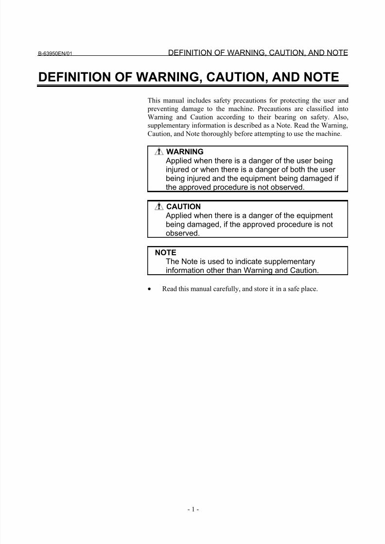
DEFINITION OF WARNING, CAUTION, AND NOTE
This manual includes safety precautions for protecting the user and
preventing damage to the machine. Precautions are classified into
Warning and Caution according to their bearing on safety. Also,
supplementary information is described as a Note. Read the Warning,
Caution, and Note thoroughly before attempting to use the machine.
WARNING
Applied when there is a danger of the user beinginjured or when there is a danger of both the user being injured and the equipment being damaged if
the approved procedure is not observed.
CAUTION
Applied when there is a danger of the equipmentbeing damaged, if the approved procedure is notobserved.
NOTE
The Note is used to indicate supplementaryinformation other than Warning and Caution.
• Read this manual carefully, and store it in a safe place.

8/21/2019 30i Parameter Manual
http://slidepdf.com/reader/full/30i-parameter-manual 4/493
8/21/2019 30i Parameter Manual
http://slidepdf.com/reader/full/30i-parameter-manual 5/493
B-63950EN/01 PREFACE
- 1 -
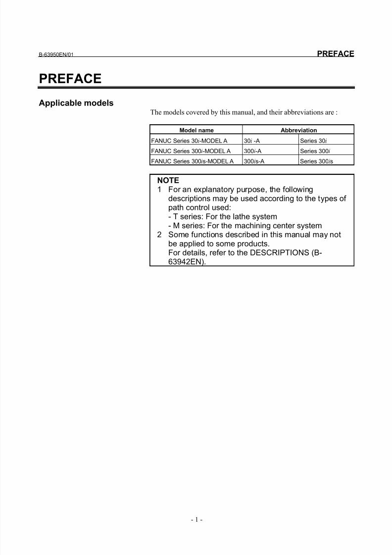
PREFACE
Applicable modelsThe models covered by this manual, and their abbreviations are :
Model name Abbreviation
FANUC Series 30i-MODEL A 30i -A Series 30i
FANUC Series 300i-MODEL A 300i-A Series 300i
FANUC Series 300is-MODEL A 300is-A Series 300is
NOTE1 For an explanatory purpose, the following
descriptions may be used according to the types of path control used:- T series: For the lathe system- M series: For the machining center system
2 Some functions described in this manual may notbe applied to some products.For details, refer to the DESCRIPTIONS (B-63942EN).
8/21/2019 30i Parameter Manual
http://slidepdf.com/reader/full/30i-parameter-manual 6/493
PREFACE B-63950EN/01
- 2 -
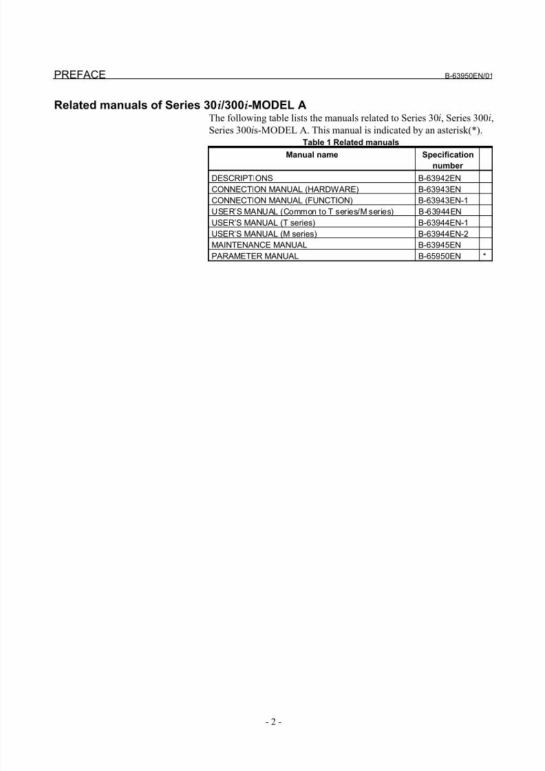
Related manuals of Series 30i /300i-MODEL AThe following table lists the manuals related to Series 30i, Series 300i,
Series 300is-MODEL A. This manual is indicated by an asterisk(*).Table 1 Related manuals
Manual name Specification
number
DESCRIPTIONS B-63942EN
CONNECTION MANUAL (HARDWARE) B-63943EN
CONNECTION MANUAL (FUNCTION) B-63943EN-1
USER’S MANUAL (Common to T series/M series) B-63944EN
USER’S MANUAL (T series) B-63944EN-1
USER’S MANUAL (M series) B-63944EN-2
MAINTENANCE MANUAL B-63945EN
PARAMETER MANUAL B-65950EN *
8/21/2019 30i Parameter Manual
http://slidepdf.com/reader/full/30i-parameter-manual 7/493
B-63950EN/01 PREFACE
- 3 -
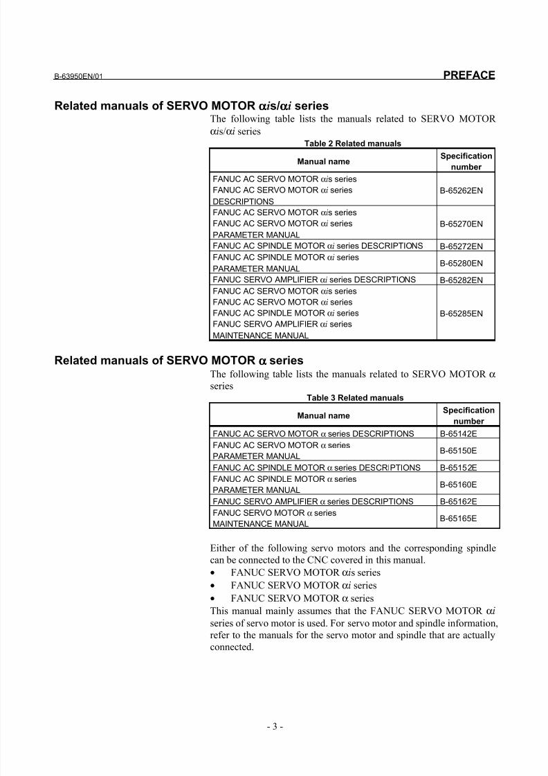
Related manuals of SERVO MOTOR ααααis/ααααi seriesThe following table lists the manuals related to SERVO MOTOR
αis/αi
series Table 2 Related manuals
Manual nameSpecification
number
FANUC AC SERVO MOTOR αis series
FANUC AC SERVO MOTOR αi series
DESCRIPTIONS
B-65262EN
FANUC AC SERVO MOTOR αis series
FANUC AC SERVO MOTOR αi series
PARAMETER MANUAL
B-65270EN
FANUC AC SPINDLE MOTOR αi series DESCRIPTIONS B-65272EN
FANUC AC SPINDLE MOTOR αi series
PARAMETER MANUAL
B-65280EN
FANUC SERVO AMPLIFIER αi series DESCRIPTIONS B-65282EN
FANUC AC SERVO MOTOR αis series
FANUC AC SERVO MOTOR αi series
FANUC AC SPINDLE MOTOR αi series
FANUC SERVO AMPLIFIER αi series
MAINTENANCE MANUAL
B-65285EN
Related manuals of SERVO MOTOR αααα seriesThe following table lists the manuals related to SERVO MOTOR α
seriesTable 3 Related manuals
Manual nameSpecification
number
FANUC AC SERVO MOTOR α series DESCRIPTIONS B-65142E
FANUC AC SERVO MOTOR α series
PARAMETER MANUALB-65150E
FANUC AC SPINDLE MOTOR α series DESCRIPTIONS B-65152E
FANUC AC SPINDLE MOTOR α series
PARAMETER MANUALB-65160E
FANUC SERVO AMPLIFIER α series DESCRIPTIONS B-65162E
FANUC SERVO MOTOR α series
MAINTENANCE MANUALB-65165E
Either of the following servo motors and the corresponding spindle
can be connected to the CNC covered in this manual.
• FANUC SERVO MOTOR αis series
• FANUC SERVO MOTOR αi series
• FANUC SERVO MOTOR α series
This manual mainly assumes that the FANUC SERVO MOTOR αi
series of servo motor is used. For servo motor and spindle information,
refer to the manuals for the servo motor and spindle that are actually
connected.

8/21/2019 30i Parameter Manual
http://slidepdf.com/reader/full/30i-parameter-manual 8/493
8/21/2019 30i Parameter Manual
http://slidepdf.com/reader/full/30i-parameter-manual 9/493
B-63950EN/01 TABLE OF CONTENTS
c - 1
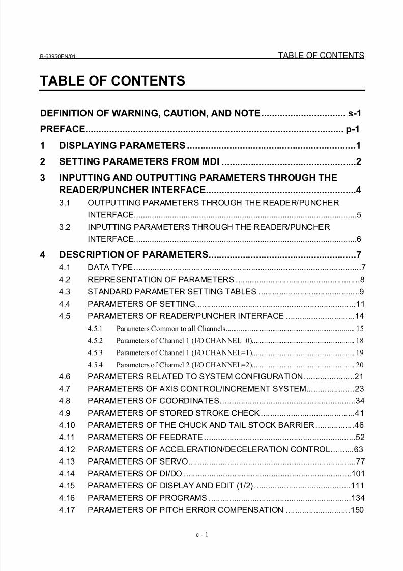
TABLE OF CONTENTS
DEFINITION OF WARNING, CAUTION, AND NOTE................................ s-1
PREFACE.................................................................................................. p-1
1 DISPLAYING PARAMETERS ................................................................1
2 SETTING PARAMETERS FROM MDI ...................................................2
3 INPUTTING AND OUTPUTTING PARAMETERS THROUGH THE
READER/PUNCHER INTERFACE.........................................................4
3.1 OUTPUTTING PARAMETERS THROUGH THE READER/PUNCHER
INTERFACE...................................................................................................5
3.2 INPUTTING PARAMETERS THROUGH THE READER/PUNCHER
INTERFACE...................................................................................................6
4 DESCRIPTION OF PARAMETERS........................................................7
4.1 DATA TYPE...................................................................................................7
4.2 REPRESENTATION OF PARAMETERS ......................................................8
4.3 STANDARD PARAMETER SETTING TABLES ............................................9
4.4 PARAMETERS OF SETTING......................................................................11
4.5 PARAMETERS OF READER/PUNCHER INTERFACE ..............................14
4.5.1 Parameters Common to all Channels..................................................................... 15
4.5.2 Parameters of Channel 1 (I/O CHANNEL=0)....................................................... 18
4.5.3 Parameters of Channel 1 (I/O CHANNEL=1)....................................................... 19
4.5.4 Parameters of Channel 2 (I/O CHANNEL=2)....................................................... 20
4.6 PARAMETERS RELATED TO SYSTEM CONFIGURATION......................21
4.7 PARAMETERS OF AXIS CONTROL/INCREMENT SYSTEM.....................23
4.8 PARAMETERS OF COORDINATES...........................................................344.9 PARAMETERS OF STORED STROKE CHECK.........................................41
4.10 PARAMETERS OF THE CHUCK AND TAIL STOCK BARRIER.................46
4.11 PARAMETERS OF FEEDRATE..................................................................52
4.12 PARAMETERS OF ACCELERATION/DECELERATION CONTROL..........63
4.13 PARAMETERS OF SERVO.........................................................................77
4.14 PARAMETERS OF DI/DO .........................................................................101
4.15 PARAMETERS OF DISPLAY AND EDIT (1/2) ..........................................111
4.16 PARAMETERS OF PROGRAMS ..............................................................1344.17 PARAMETERS OF PITCH ERROR COMPENSATION ............................150
8/21/2019 30i Parameter Manual
http://slidepdf.com/reader/full/30i-parameter-manual 10/493
TABLE OF CONTENTS B-63950EN/01
c - 2
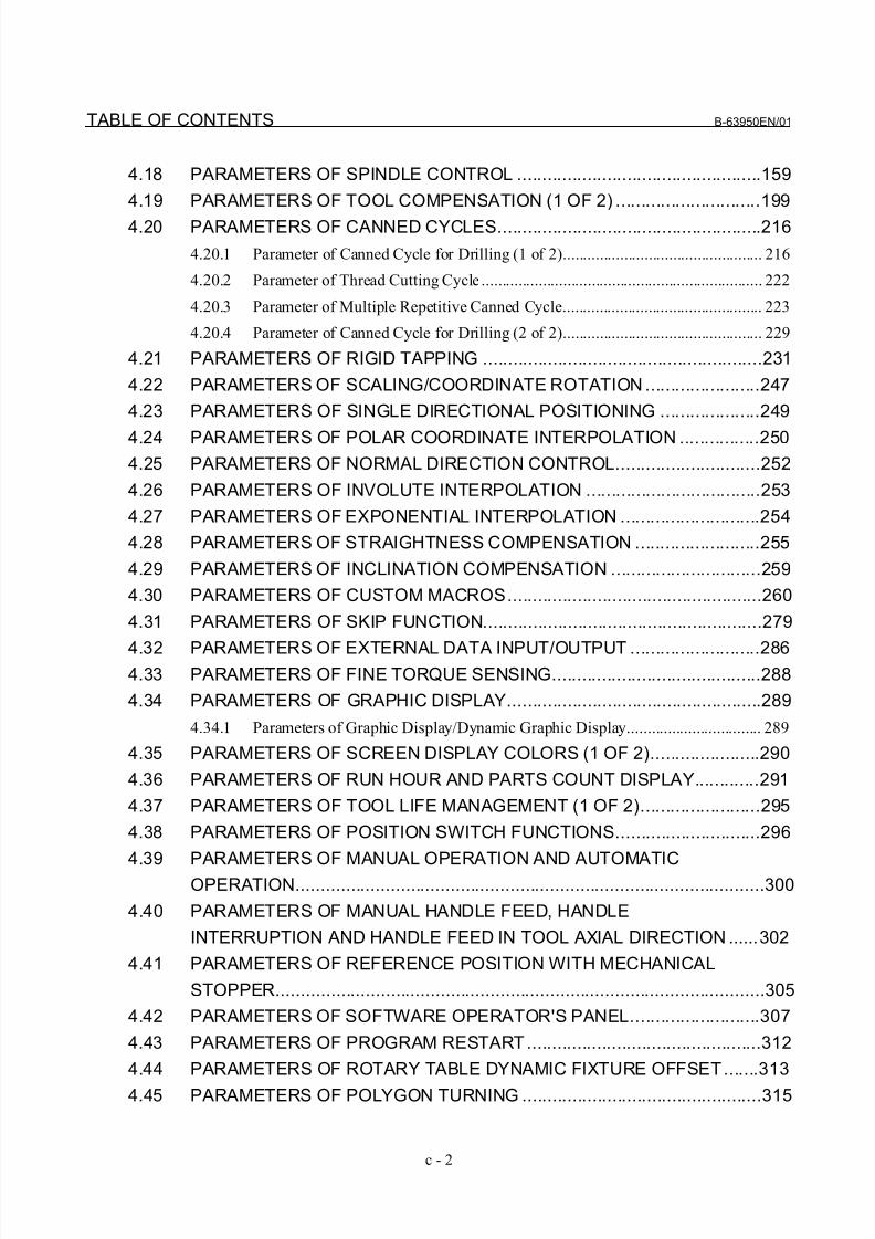
4.18 PARAMETERS OF SPINDLE CONTROL .................................................159
4.19 PARAMETERS OF TOOL COMPENSATION (1 OF 2) .............................199
4.20 PARAMETERS OF CANNED CYCLES.....................................................216
4.20.1 Parameter of Canned Cycle for Drilling (1 of 2)................................................. 216
4.20.2 Parameter of Thread Cutting Cycle ..................................................................... 222
4.20.3 Parameter of Multiple Repetitive Canned Cycle................................................. 223
4.20.4 Parameter of Canned Cycle for Drilling (2 of 2)................................................. 229
4.21 PARAMETERS OF RIGID TAPPING ........................................................231
4.22 PARAMETERS OF SCALING/COORDINATE ROTATION .......................247
4.23 PARAMETERS OF SINGLE DIRECTIONAL POSITIONING ....................249
4.24 PARAMETERS OF POLAR COORDINATE INTERPOLATION ................250
4.25 PARAMETERS OF NORMAL DIRECTION CONTROL.............................252
4.26 PARAMETERS OF INVOLUTE INTERPOLATION ...................................253
4.27 PARAMETERS OF EXPONENTIAL INTERPOLATION ............................254
4.28 PARAMETERS OF STRAIGHTNESS COMPENSATION .........................255
4.29 PARAMETERS OF INCLINATION COMPENSATION ..............................259
4.30 PARAMETERS OF CUSTOM MACROS...................................................260
4.31 PARAMETERS OF SKIP FUNCTION........................................................279
4.32 PARAMETERS OF EXTERNAL DATA INPUT/OUTPUT ..........................2864.33 PARAMETERS OF FINE TORQUE SENSING..........................................288
4.34 PARAMETERS OF GRAPHIC DISPLAY...................................................289
4.34.1 Parameters of Graphic Display/Dynamic Graphic Display................................. 289
4.35 PARAMETERS OF SCREEN DISPLAY COLORS (1 OF 2)......................290
4.36 PARAMETERS OF RUN HOUR AND PARTS COUNT DISPLAY.............291
4.37 PARAMETERS OF TOOL LIFE MANAGEMENT (1 OF 2)........................295
4.38 PARAMETERS OF POSITION SWITCH FUNCTIONS.............................296
4.39 PARAMETERS OF MANUAL OPERATION AND AUTOMATIC
OPERATION..............................................................................................300
4.40 PARAMETERS OF MANUAL HANDLE FEED, HANDLE
INTERRUPTION AND HANDLE FEED IN TOOL AXIAL DIRECTION ......302
4.41 PARAMETERS OF REFERENCE POSITION WITH MECHANICAL
STOPPER..................................................................................................305
4.42 PARAMETERS OF SOFTWARE OPERATOR'S PANEL..........................307
4.43 PARAMETERS OF PROGRAM RESTART...............................................312
4.44 PARAMETERS OF ROTARY TABLE DYNAMIC FIXTURE OFFSET.......313
4.45 PARAMETERS OF POLYGON TURNING ................................................315

8/21/2019 30i Parameter Manual
http://slidepdf.com/reader/full/30i-parameter-manual 11/493
B-63950EN/01 TABLE OF CONTENTS
c - 3
4.46 PARAMETERS OF THE HOBBING MACHINE AND SIMPLE
ELECTRIC GEAR BOX (EGB) ..................................................................325
4.47 PARAMETERS OF AXIS CONTROL BY PMC..........................................326
4.48 PARAMETERS OF MULTI-PATH CONTROL ...........................................334
4.49 PARAMETERS OF INTERFERENCE CHECK BETWEEN PATHS..........336
4.50 PARAMETERS OF AXIS RECOMPOSITION AND SUPERIMPOSED
CONTROL .................................................................................................341
4.51 PARAMETERS OF ANGULAR AXIS CONTROL ......................................354
4.52 PARAMETERS OF FEED AXIS SYNCHRONOUS CONTROL.................356
4.53 PARAMETERS OF SEQUENCE NUMBER COMPARISON AND STOP..365
4.54 PARAMETERS OF AI CONTOUR CONTROL ..........................................366
4.55 PARAMETERS OF HIGH-SPEED POSITION SWITCH (1 OF 2) .............370
4.56 OTHER PARAMETERS.............................................................................382
4.57 PARAMETERS OF MAINTENANCE .........................................................385
4.58 PARAMETERS OF THE INCORRECT OPERATION PREVENTION
FUNCTION ................................................................................................386
4.59 PARAMETERS OF SCREEN DISPLAY COLORS (2 OF 2)......................397
4.60 PARAMETERS OF PMC ...........................................................................399
4.61 PARAMETERS OF HIGH-SPEED POSITION SWITCH (2 OF 2) .............4074.62 PARAMETERS OF MALFUNCTION PROTECTION.................................409
4.63 PARAMETERS OF MANUAL HANDLE (2 OF 2) ......................................410
4.64 PARAMETERS OF DISPLAY AND EDIT (2 OF 2) ....................................416
4.65 PARAMETERS OF TOOL LIFE MANAGEMENT (2 OF 2)........................418
4.66 PARAMETERS OF THE MACHINING CONDITION SELECTION
FUNCTION ................................................................................................426
4.67 PARAMETERS OF FSSB..........................................................................433
4.68 PARAMETERS OF AI CONTOUR CONTROL ..........................................444
4.69 PARAMETERS OF CYLINDRICAL INTERPOLATION..............................447
4.70 PARAMETERS OF OPTIMAL TORQUE
ACCELERATION/DECELERATION ..........................................................450
4.71 PARAMETERS OF NANO SMOOTHING..................................................454
4.72 PARAMETERS OF TOOL COMPENSATION (2 OF 2) .............................455
4.73 PARAMETERS OF 5-AXIS MACHINING FUNCTION...............................458
APPENDIX
A CHARACTER CODE LIST .................................................................477

8/21/2019 30i Parameter Manual
http://slidepdf.com/reader/full/30i-parameter-manual 12/493
8/21/2019 30i Parameter Manual
http://slidepdf.com/reader/full/30i-parameter-manual 13/493
B-63950EN/01 1.DISPLAYING PARAMETERS
- 1 -
1 DISPLAYING PARAMETERS
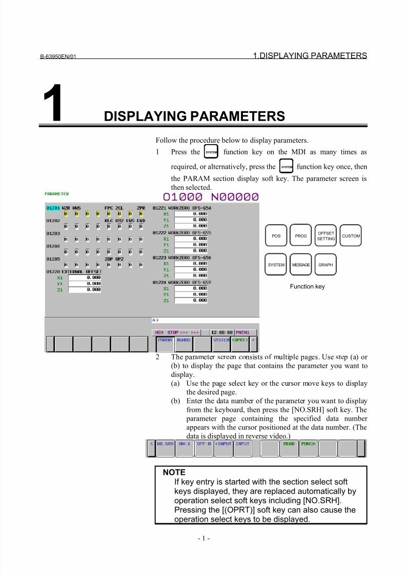
Follow the procedure below to display parameters.
1 Press the SYSTEM function key on the MDI as many times as
required, or alternatively, press the SYSTEM function key once, then
the PARAM section display soft key. The parameter screen is
then selected.
POS PROGOFFSET
SETTINGCUSTOM
SYSTEM MESSAGE GRAPH
Function key
2 The parameter screen consists of multiple pages. Use step (a) or
(b) to display the page that contains the parameter you want to
display.
(a) Use the page select key or the cursor move keys to display
the desired page.
(b) Enter the data number of the parameter you want to displayfrom the keyboard, then press the [NO.SRH] soft key. The
parameter page containing the specified data number
appears with the cursor positioned at the data number. (The
data is displayed in reverse video.)
NOTEIf key entry is started with the section select softkeys displayed, they are replaced automatically by
operation select soft keys including [NO.SRH].Pressing the [(OPRT)] soft key can also cause theoperation select keys to be displayed.
8/21/2019 30i Parameter Manual
http://slidepdf.com/reader/full/30i-parameter-manual 14/493
2.SETTING PARAMETERS FROM MDI B-63950EN/01
- 2 -
2 SETTING PARAMETERS FROM MDI
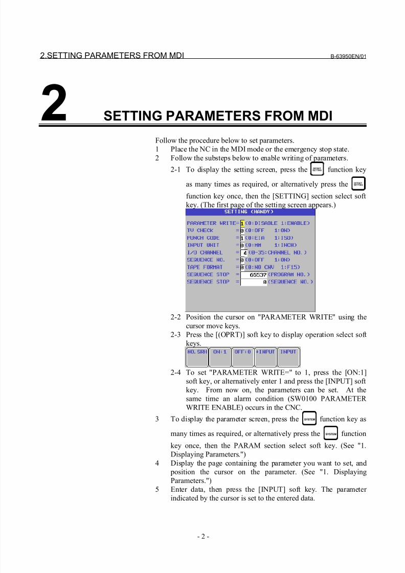
Follow the procedure below to set parameters.
1 Place the NC in the MDI mode or the emergency stop state.
2 Follow the substeps below to enable writing of parameters.
2-1 To display the setting screen, press the OFFSETSETTING function key
as many times as required, or alternatively press the OFFSETSETTING
function key once, then the [SETTING] section select soft
key. (The first page of the setting screen appears.)
2-2 Position the cursor on "PARAMETER WRITE" using the
cursor move keys.
2-3 Press the [(OPRT)] soft key to display operation select soft
keys.
2-4 To set "PARAMETER WRITE=" to 1, press the [ON:1]
soft key, or alternatively enter 1 and press the [INPUT] soft
key. From now on, the parameters can be set. At the
same time an alarm condition (SW0100 PARAMETER WRITE ENABLE) occurs in the CNC.
3 To display the parameter screen, press the SYSTEM function key as
many times as required, or alternatively press the SYSTEM function
key once, then the PARAM section select soft key. (See "1.
Displaying Parameters.")
4 Display the page containing the parameter you want to set, and
position the cursor on the parameter. (See "1. Displaying
Parameters.")
5 Enter data, then press the [INPUT] soft key. The parameter
indicated by the cursor is set to the entered data.
8/21/2019 30i Parameter Manual
http://slidepdf.com/reader/full/30i-parameter-manual 15/493
B-63950EN/01 2.SETTING PARAMETERS FROM MDI
- 3 -
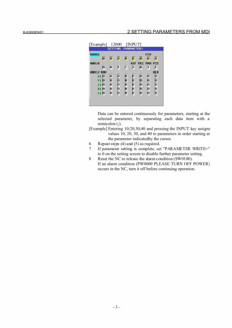
[Example] 12000 [INPUT]
Data can be entered continuously for parameters, starting at theselected parameter, by separating each data item with a
semicolon (;).
[Example] Entering 10;20;30;40 and pressing the INPUT key assigns
values 10, 20, 30, and 40 to parameters in order starting at
the parameter indicatedby the cursor.
6 Repeat steps (4) and (5) as required.
7 If parameter setting is complete, set "PARAMETER WRITE="
to 0 on the setting screen to disable further parameter setting.
8 Reset the NC to release the alarm condition (SW0100).
If an alarm condition (PW0000 PLEASE TURN OFF POWER)
occurs in the NC, turn it off before continuing operation.
8/21/2019 30i Parameter Manual
http://slidepdf.com/reader/full/30i-parameter-manual 16/493
3.INPUTTING AND OUTPUTTING PARAMETERS THROUGH THE READER/PUNCHER INTERFACE B-63950EN/01
- 4 -
3 INPUTTING AND OUTPUTTINGPARAMETERS THROUGH THEREADER/PUNCHER INTERFACE
This section explains the parameter input/output procedures for
input/output devices connected to the reader/puncher interface.
The following description assumes the input/output devices are ready
for input/output. It also assumes parameters peculiar to theinput/output devices, such as the baud rate and the number of stop bits,
have been set in advance. (See Section 4.5.)
8/21/2019 30i Parameter Manual
http://slidepdf.com/reader/full/30i-parameter-manual 17/493
B-63950EN/01 3.INPUTTING AND OUTPUTTING PARAMETERS THROUGH THE READER/PUNCHER INTERFACE
- 5 -
3.1 OUTPUTTING PARAMETERS THROUGH THE
READER/PUNCHER INTERFACE
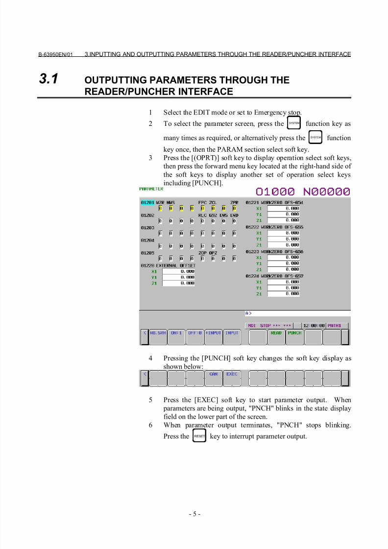
1 Select the EDIT mode or set to Emergency stop.
2 To select the parameter screen, press the SYSTEM function key as
many times as required, or alternatively press the SYSTEM function
key once, then the PARAM section select soft key.
3 Press the [(OPRT)] soft key to display operation select soft keys,
then press the forward menu key located at the right-hand side of
the soft keys to display another set of operation select keys
including [PUNCH].
4 Pressing the [PUNCH] soft key changes the soft key display as
shown below:
5 Press the [EXEC] soft key to start parameter output. When
parameters are being output, "PNCH" blinks in the state display
field on the lower part of the screen.
6 When parameter output terminates, "PNCH" stops blinking.
Press the RESET key to interrupt parameter output.
8/21/2019 30i Parameter Manual
http://slidepdf.com/reader/full/30i-parameter-manual 18/493
3.INPUTTING AND OUTPUTTING PARAMETERS THROUGH THE READER/PUNCHER INTERFACE B-63950EN/01
- 6 -
3.2 INPUTTING PARAMETERS THROUGH THE
READER/PUNCHER INTERFACE
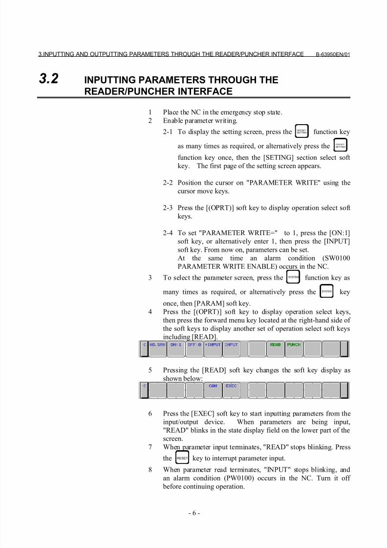
1 Place the NC in the emergency stop state.
2 Enable parameter writing.
2-1 To display the setting screen, press the OFFSETSETTING function key
as many times as required, or alternatively press the OFFSETSETTING
function key once, then the [SETING] section select soft
key. The first page of the setting screen appears.
2-2 Position the cursor on "PARAMETER WRITE" using the
cursor move keys.
2-3 Press the [(OPRT)] soft key to display operation select soft
keys.
2-4 To set "PARAMETER WRITE=" to 1, press the [ON:1]
soft key, or alternatively enter 1, then press the [INPUT]
soft key. From now on, parameters can be set.
At the same time an alarm condition (SW0100
PARAMETER WRITE ENABLE) occurs in the NC.
3 To select the parameter screen, press the SYSTEM function key as
many times as required, or alternatively press the SYSTEM key
once, then [PARAM] soft key.
4 Press the [(OPRT)] soft key to display operation select keys,
then press the forward menu key located at the right-hand side of
the soft keys to display another set of operation select soft keys
including [READ].
5 Pressing the [READ] soft key changes the soft key display as
shown below:
6 Press the [EXEC] soft key to start inputting parameters from the
input/output device. When parameters are being input,
"READ" blinks in the state display field on the lower part of the
screen.
7 When parameter input terminates, "READ" stops blinking. Press
the RESET key to interrupt parameter input.
8 When parameter read terminates, "INPUT" stops blinking, and
an alarm condition (PW0100) occurs in the NC. Turn it off before continuing operation.
8/21/2019 30i Parameter Manual
http://slidepdf.com/reader/full/30i-parameter-manual 19/493
B-63950EN/01 4.DESCRIPTION OF PARAMETERS
- 7 -
4 DESCRIPTION OF PARAMETERS
4.1 DATA TYPE
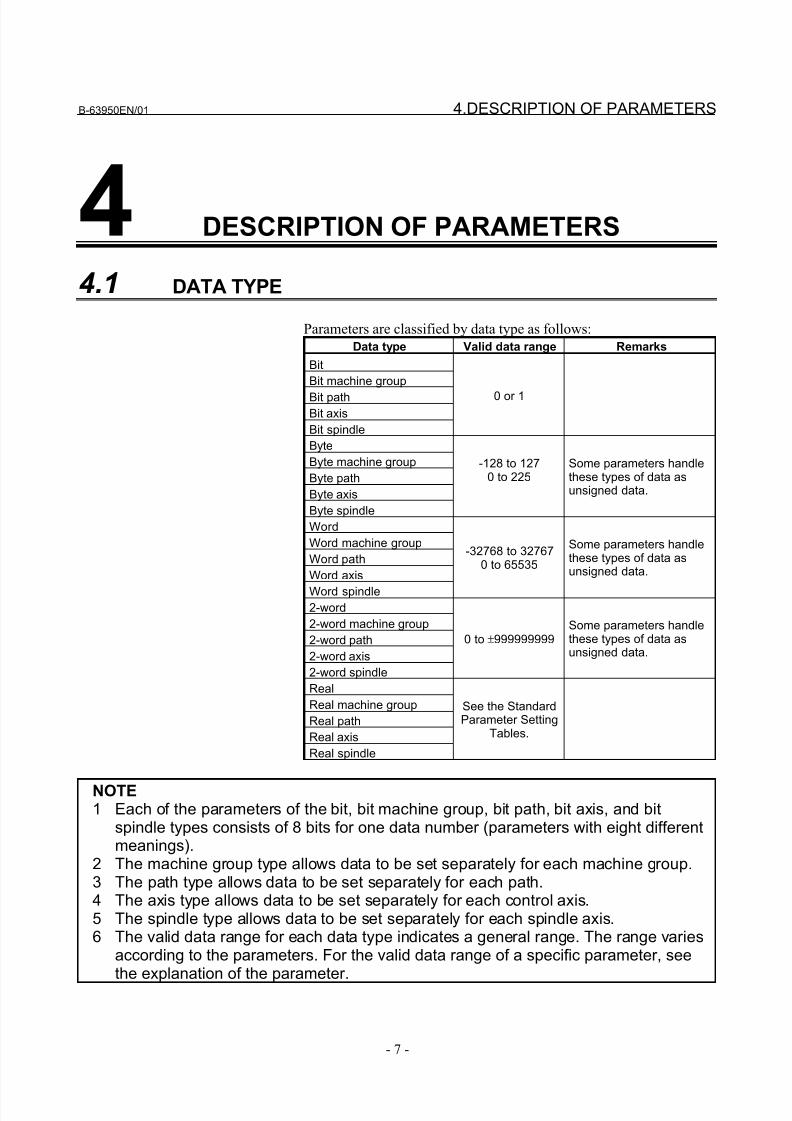
Parameters are classified by data type as follows:
Data type Valid data range Remarks
Bit
Bit machine group
Bit path
Bit axis
Bit spindle
0 or 1
Byte
Byte machine group
Byte path
Byte axis
Byte spindle
-128 to 1270 to 225
Some parameters handlethese types of data asunsigned data.
Word
Word machine group
Word path
Word axis
Word spindle
-32768 to 327670 to 65535
Some parameters handlethese types of data asunsigned data.
2-word
2-word machine group
2-word path
2-word axis
2-word spindle
0 to ±999999999Some parameters handlethese types of data asunsigned data.
Real
Real machine group
Real path
Real axis
Real spindle
See the StandardParameter Setting
Tables.
NOTE1 Each of the parameters of the bit, bit machine group, bit path, bit axis, and bit
spindle types consists of 8 bits for one data number (parameters with eight differentmeanings).
2 The machine group type allows data to be set separately for each machine group.3 The path type allows data to be set separately for each path.4 The axis type allows data to be set separately for each control axis.5 The spindle type allows data to be set separately for each spindle axis.6 The valid data range for each data type indicates a general range. The range varies
according to the parameters. For the valid data range of a specific parameter, seethe explanation of the parameter.
8/21/2019 30i Parameter Manual
http://slidepdf.com/reader/full/30i-parameter-manual 20/493
4.DESCRIPTION OF PARAMETERS B-63950EN/01
- 8 -
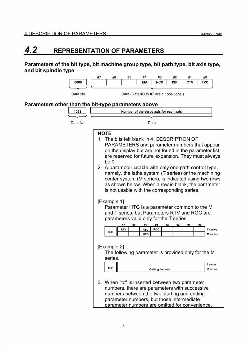
4.2 REPRESENTATION OF PARAMETERS
Parameters of the bit type, bit machine group type, bit path type, bit axis type,and bit spindle type
#7 #6 #5 #4 #3 #2 #1 #0
0000 EIA NCR ISP CTV TVC
Parameters other than the bit-type parameters above
1023 Number of the servo axis for each axis
NOTE1 The bits left blank in 4. DESCRIPTION OF
PARAMETERS and parameter numbers that appear on the display but are not found in the parameter listare reserved for future expansion. They must alwaysbe 0.
2 A parameter usable with only one path control type,namely, the lathe system (T series) or the machiningcenter system (M series), is indicated using two rows
as shown below. When a row is blank, the parameter is not usable with the corresponding series.
[Example 1]Parameter HTG is a parameter common to the Mand T series, but Parameters RTV and ROC areparameters valid only for the T series.
1403RTV ROCHTG
HTG
T series
M series
#7 #6 #5 #4 #3 #2 #1 #0
[Example 2]The following parameter is provided only for the Mseries.
1411Cutting feedrate
T series
M series
3. When "to" is inserted between two parameter numbers, there are parameters with successivenumbers between the two starting and endingparameter numbers, but those intermediate
parameter numbers are omitted for convenience.
Data No. Data (Data #0 to #7 are bit positions.)
Data No. Data
8/21/2019 30i Parameter Manual
http://slidepdf.com/reader/full/30i-parameter-manual 21/493
B-63950EN/01 4.DESCRIPTION OF PARAMETERS
- 9 -
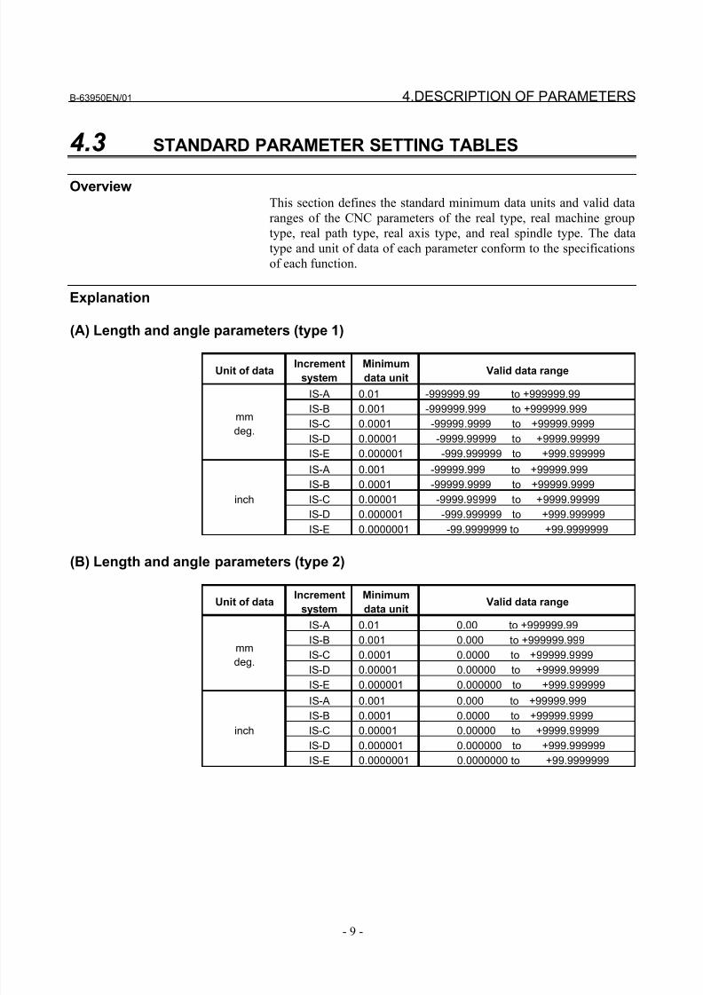
4.3 STANDARD PARAMETER SETTING TABLES
OverviewThis section defines the standard minimum data units and valid data
ranges of the CNC parameters of the real type, real machine group
type, real path type, real axis type, and real spindle type. The data
type and unit of data of each parameter conform to the specifications
of each function.
Explanation
(A) Length and angle parameters (type 1)
Unit of dataIncrement
system
Minimum
data unitValid data range
IS-A 0.01 -999999.99 to +999999.99
IS-B 0.001 -999999.999 to +999999.999
IS-C 0.0001 -99999.9999 to +99999.9999
IS-D 0.00001 -9999.99999 to +9999.99999
mm
deg.
IS-E 0.000001 -999.999999 to +999.999999
IS-A 0.001 -99999.999 to +99999.999
IS-B 0.0001 -99999.9999 to +99999.9999
IS-C 0.00001 -9999.99999 to +9999.99999
IS-D 0.000001 -999.999999 to +999.999999
inch
IS-E 0.0000001 -99.9999999 to +99.9999999
(B) Length and angle parameters (type 2)
Unit of dataIncrement
system
Minimum
data unitValid data range
IS-A 0.01 0.00 to +999999.99
IS-B 0.001 0.000 to +999999.999
IS-C 0.0001 0.0000 to +99999.9999
IS-D 0.00001 0.00000 to +9999.99999
mm
deg.
IS-E 0.000001 0.000000 to +999.999999
IS-A 0.001 0.000 to +99999.999
IS-B 0.0001 0.0000 to +99999.9999
IS-C 0.00001 0.00000 to +9999.99999
IS-D 0.000001 0.000000 to +999.999999
inch
IS-E 0.0000001 0.0000000 to +99.9999999
8/21/2019 30i Parameter Manual
http://slidepdf.com/reader/full/30i-parameter-manual 22/493
4.DESCRIPTION OF PARAMETERS B-63950EN/01
- 10 -
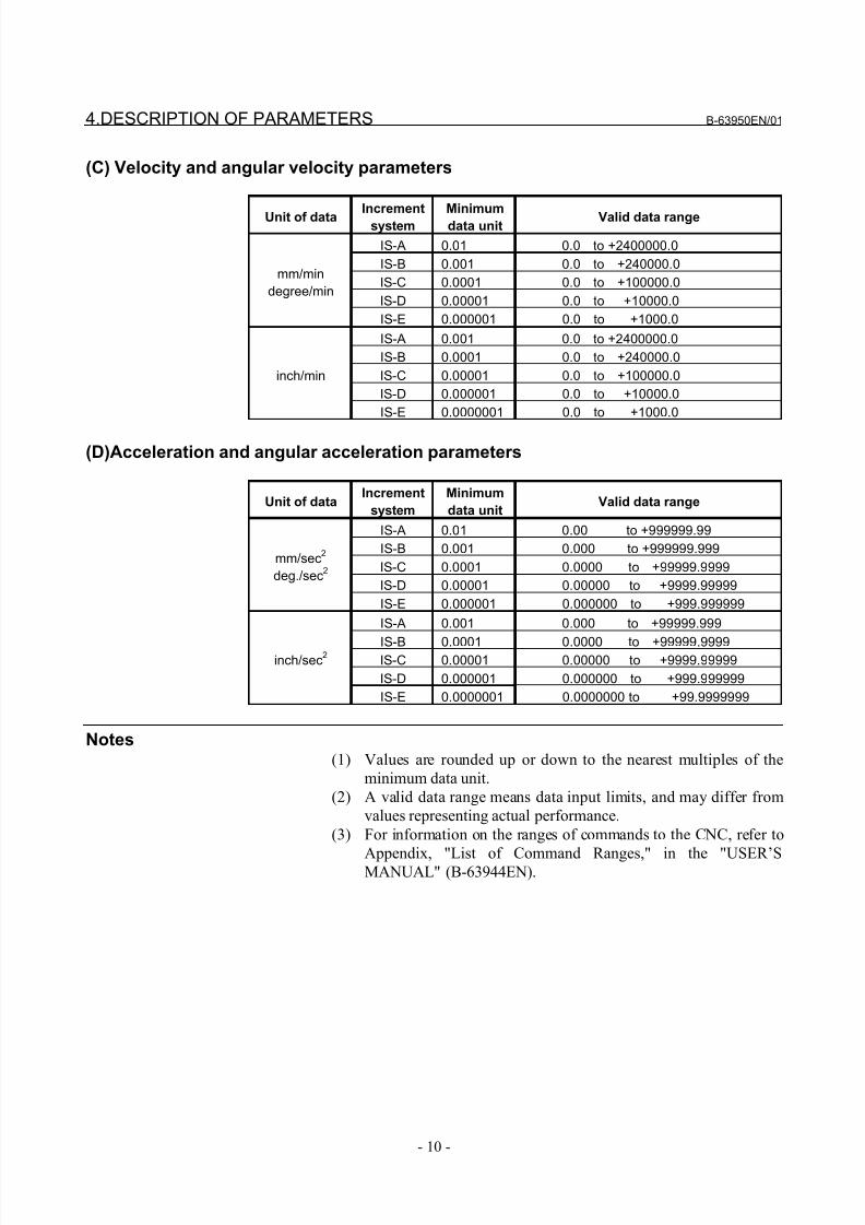
(C) Velocity and angular velocity parameters
Unit of data Incrementsystem Minimumdata unit Valid data range
IS-A 0.01 0.0 to +2400000.0
IS-B 0.001 0.0 to +240000.0
IS-C 0.0001 0.0 to +100000.0
IS-D 0.00001 0.0 to +10000.0
mm/min
degree/min
IS-E 0.000001 0.0 to +1000.0
IS-A 0.001 0.0 to +2400000.0
IS-B 0.0001 0.0 to +240000.0
IS-C 0.00001 0.0 to +100000.0
IS-D 0.000001 0.0 to +10000.0
inch/min
IS-E 0.0000001 0.0 to +1000.0
(D)Acceleration and angular acceleration parameters
Unit of dataIncrement
system
Minimum
data unitValid data range
IS-A 0.01 0.00 to +999999.99
IS-B 0.001 0.000 to +999999.999
IS-C 0.0001 0.0000 to +99999.9999
IS-D 0.00001 0.00000 to +9999.99999
mm/sec2
deg./sec2
IS-E 0.000001 0.000000 to +999.999999
IS-A 0.001 0.000 to +99999.999
IS-B 0.0001 0.0000 to +99999.9999IS-C 0.00001 0.00000 to +9999.99999
IS-D 0.000001 0.000000 to +999.999999
inch/sec2
IS-E 0.0000001 0.0000000 to +99.9999999
Notes(1) Values are rounded up or down to the nearest multiples of the
minimum data unit.
(2) A valid data range means data input limits, and may differ from
values representing actual performance.
(3) For information on the ranges of commands to the CNC, refer to
Appendix, "List of Command Ranges," in the "USER’SMANUAL" (B-63944EN).
8/21/2019 30i Parameter Manual
http://slidepdf.com/reader/full/30i-parameter-manual 23/493
B-63950EN/01 4.DESCRIPTION OF PARAMETERS
- 11 -
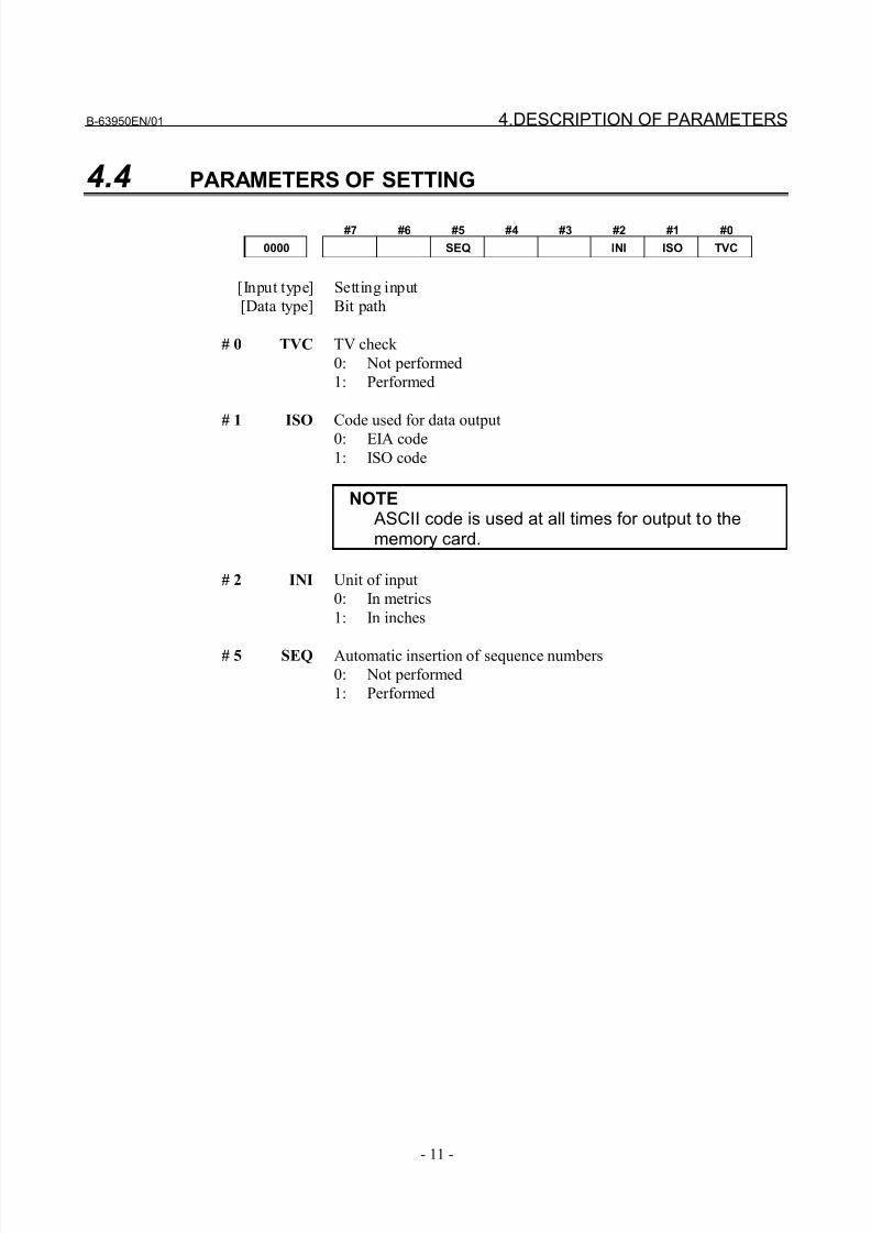
4.4 PARAMETERS OF SETTING
#7 #6 #5 #4 #3 #2 #1 #0
0000 SEQ INI ISO TVC
[Input type] Setting input
[Data type] Bit path
# 0 TVC TV check
0: Not performed
1: Performed
# 1 ISO Code used for data output
0: EIA code
1: ISO code
NOTE ASCII code is used at all times for output to thememory card.
# 2 INI Unit of input
0: In metrics
1: In inches
# 5 SEQ Automatic insertion of sequence numbers
0: Not performed
1: Performed
8/21/2019 30i Parameter Manual
http://slidepdf.com/reader/full/30i-parameter-manual 24/493
4.DESCRIPTION OF PARAMETERS B-63950EN/01
- 12 -
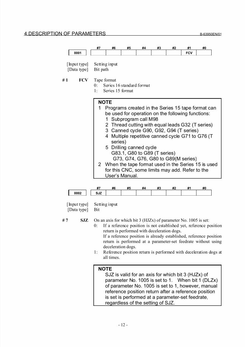
#7 #6 #5 #4 #3 #2 #1 #0
0001 FCV
[Input type] Setting input
[Data type] Bit path
# 1 FCV Tape format
0: Series 16 standard format
1: Series 15 format
NOTE1 Programs created in the Series 15 tape format can
be used for operation on the following functions:
1 Subprogram call M982 Thread cutting with equal leads G32 (T series)3 Canned cycle G90, G92, G94 (T series)4 Multiple repetitive canned cycle G71 to G76 (T
series)5 Drilling canned cycle
G83.1, G80 to G89 (T series) G73, G74, G76, G80 to G89(M series)
2 When the tape format used in the Series 15 is usedfor this CNC, some limits may add. Refer to theUser’s Manual.
#7 #6 #5 #4 #3 #2 #1 #0
0002 SJZ
[Input type] Setting input
[Data type] Bit
# 7 SJZ On an axis for which bit 3 (HJZx) of parameter No. 1005 is set:
0: If a reference position is not established yet, reference position
return is performed with deceleration dogs.
If a reference position is already established, reference position
return is performed at a parameter-set feedrate without usingdeceleration dogs.
1: Reference position return is performed with deceleration dogs at
all times.
NOTESJZ is valid for an axis for which bit 3 (HJZx) of parameter No. 1005 is set to 1. When bit 1 (DLZx)of parameter No. 1005 is set to 1, however, manualreference position return after a reference positionis set is performed at a parameter-set feedrate,
regardless of the setting of SJZ.
8/21/2019 30i Parameter Manual
http://slidepdf.com/reader/full/30i-parameter-manual 25/493
B-63950EN/01 4.DESCRIPTION OF PARAMETERS
- 13 -
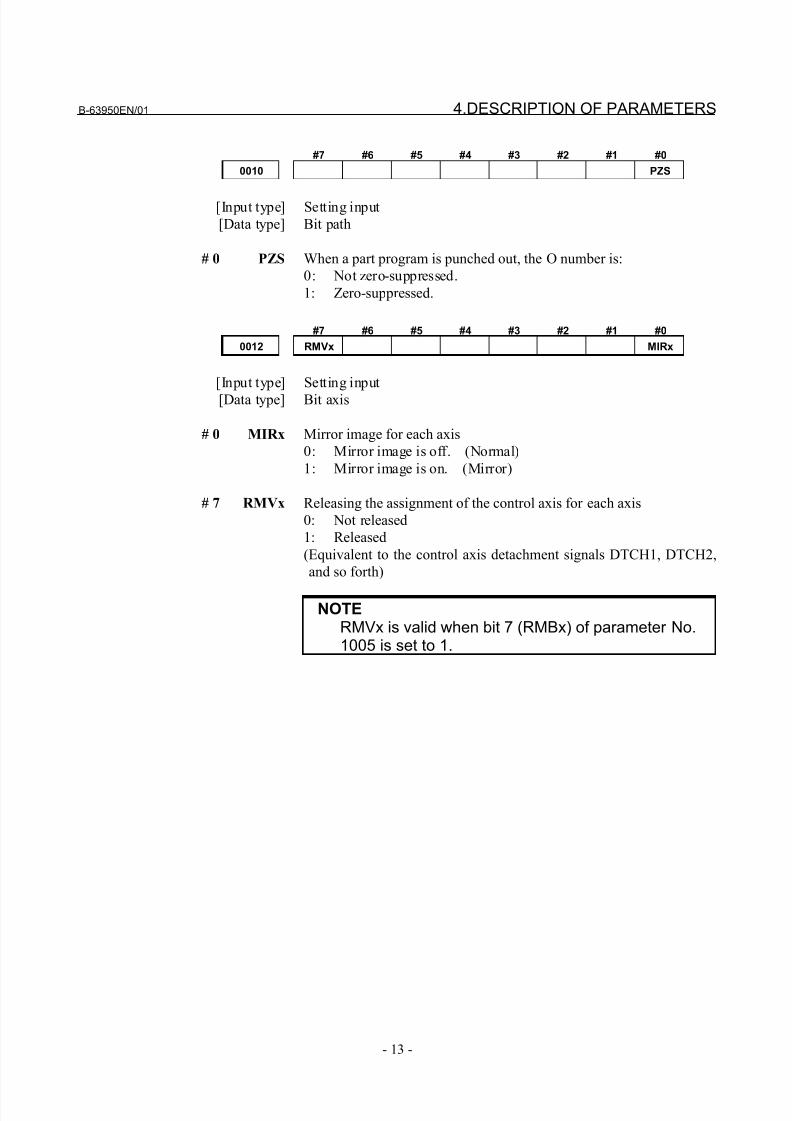
#7 #6 #5 #4 #3 #2 #1 #0
0010 PZS
[Input type] Setting input
[Data type] Bit path
# 0 PZS When a part program is punched out, the O number is:
0: Not zero-suppressed.
1: Zero-suppressed.
#7 #6 #5 #4 #3 #2 #1 #0
0012 RMVx MIRx
[Input type] Setting input
[Data type] Bit axis
# 0 MIRx Mirror image for each axis
0: Mirror image is off. (Normal)
1: Mirror image is on. (Mirror)
# 7 RMVx Releasing the assignment of the control axis for each axis
0: Not released
1: Released
(Equivalent to the control axis detachment signals DTCH1, DTCH2,
and so forth)
NOTERMVx is valid when bit 7 (RMBx) of parameter No.1005 is set to 1.
8/21/2019 30i Parameter Manual
http://slidepdf.com/reader/full/30i-parameter-manual 26/493
4.DESCRIPTION OF PARAMETERS B-63950EN/01
- 14 -
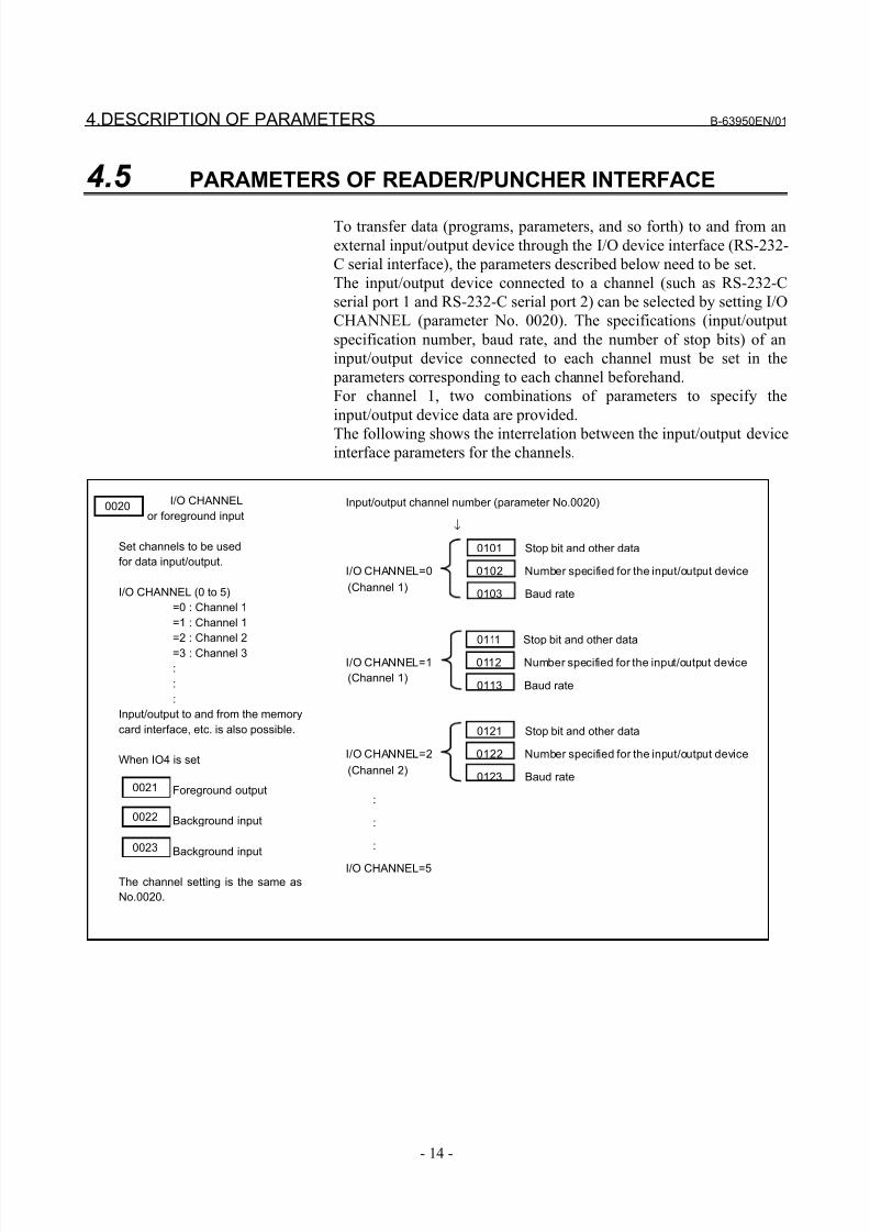
4.5 PARAMETERS OF READER/PUNCHER INTERFACE
To transfer data (programs, parameters, and so forth) to and from an
external input/output device through the I/O device interface (RS-232-
C serial interface), the parameters described below need to be set.
The input/output device connected to a channel (such as RS-232-C
serial port 1 and RS-232-C serial port 2) can be selected by setting I/O
CHANNEL (parameter No. 0020). The specifications (input/output
specification number, baud rate, and the number of stop bits) of an
input/output device connected to each channel must be set in the
parameters corresponding to each channel beforehand.
For channel 1, two combinations of parameters to specify the
input/output device data are provided.
The following shows the interrelation between the input/output deviceinterface parameters for the channels.
I/O CHANNEL
or foreground input
Set channels to be used
for data input/output.
I/O CHANNEL (0 to 5)
=0 : Channel 1
=1 : Channel 1
=2 : Channel 2
=3 : Channel 3
:
:
:
Input/output to and from the memory
card interface, etc. is also possible.
When IO4 is set
Foreground output
Background input
Background input
The channel setting is the same as
No.0020.
Input/output channel number (parameter No.0020)
↓
0101 Stop bit and other data
I/O CHANNEL=0 0102 Number specified for the input/output device
0103 Baud rate
0111 Stop bit and other data
I/O CHANNEL=1 0112 Number specified for the input/output device
0113 Baud rate
0121 Stop bit and other data
I/O CHANNEL=2 0122 Number specified for the input/output device
0123 Baud rate
:
:
:
I/O CHANNEL=5
(Channel 1)
(Channel 1)
(Channel 2)
0020
0021
0022
0023
8/21/2019 30i Parameter Manual
http://slidepdf.com/reader/full/30i-parameter-manual 27/493
B-63950EN/01 4.DESCRIPTION OF PARAMETERS
- 15 -
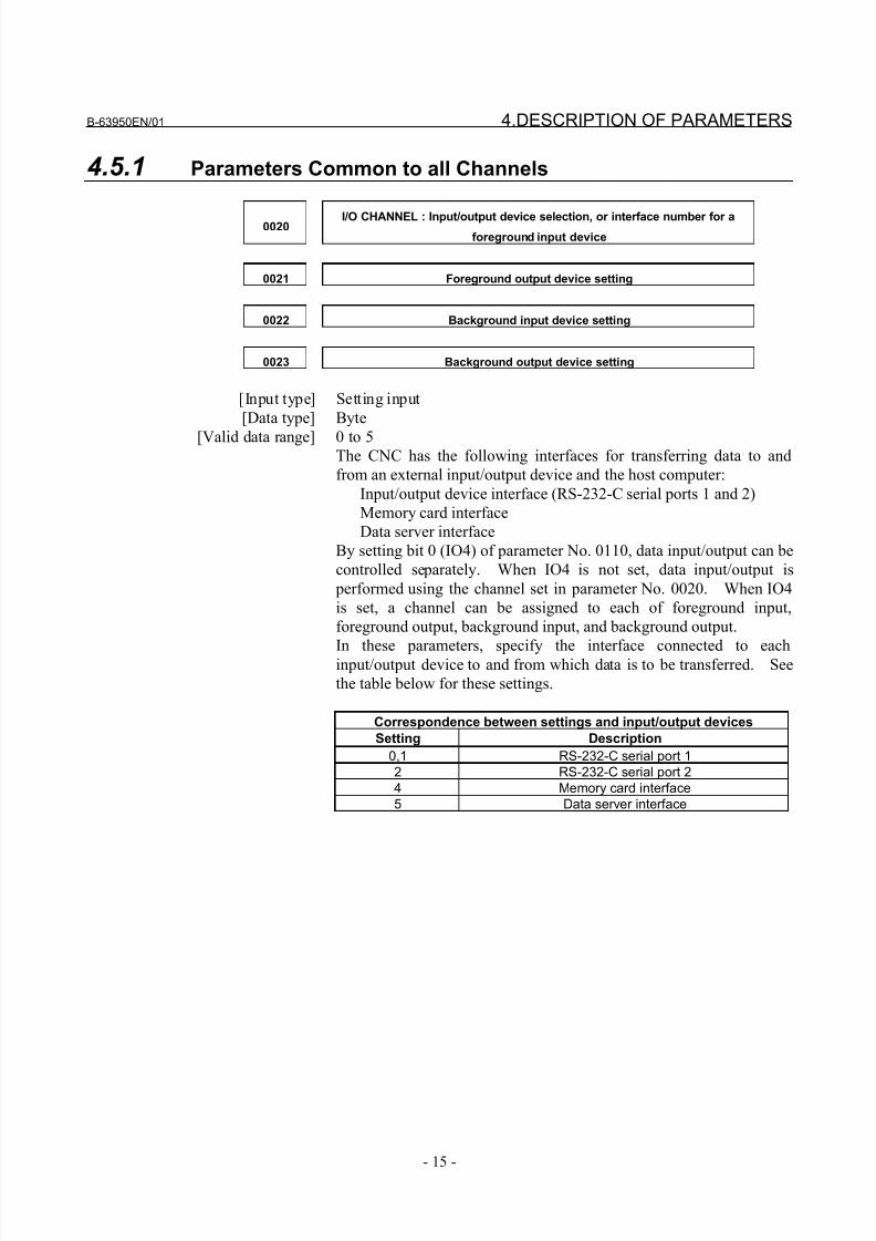
4.5.1 Parameters Common to all Channels
0020 I/O CHANNEL : Input/output device selection, or interface number for a
foreground input device
0021 Foreground output device setting
0022 Background input device setting
0023 Background output device setting
[Input type] Setting input
[Data type] Byte
[Valid data range] 0 to 5The CNC has the following interfaces for transferring data to and
from an external input/output device and the host computer:
Input/output device interface (RS-232-C serial ports 1 and 2)
Memory card interface
Data server interface
By setting bit 0 (IO4) of parameter No. 0110, data input/output can be
controlled separately. When IO4 is not set, data input/output is
performed using the channel set in parameter No. 0020. When IO4
is set, a channel can be assigned to each of foreground input,
foreground output, background input, and background output.
In these parameters, specify the interface connected to eachinput/output device to and from which data is to be transferred. See
the table below for these settings.
Correspondence between settings and input/output devices
Setting Description
0,1 RS-232-C serial port 1
2 RS-232-C serial port 2
4 Memory card interface
5 Data server interface
8/21/2019 30i Parameter Manual
http://slidepdf.com/reader/full/30i-parameter-manual 28/493
4.DESCRIPTION OF PARAMETERS B-63950EN/01
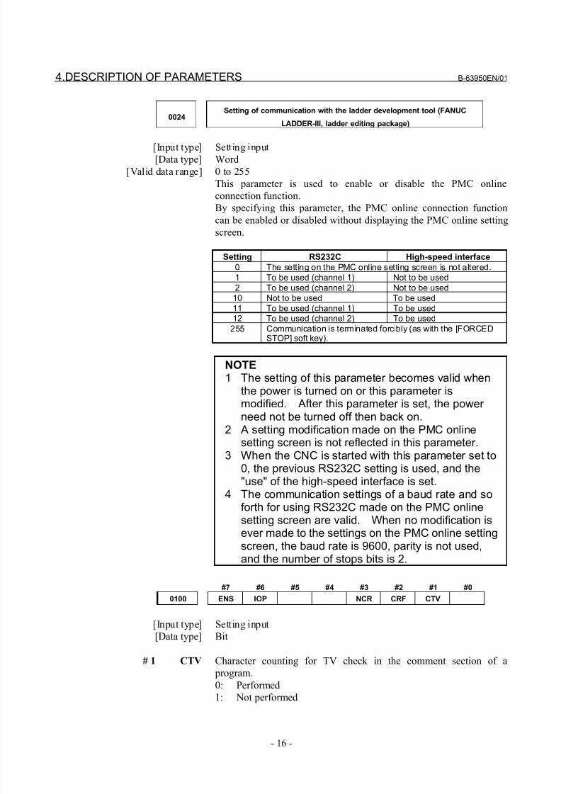
- 16 -
0024Setting of communication with the ladder development tool (FANUC
LADDER-III, ladder editing package)
[Input type] Setting input
[Data type] Word
[Valid data range] 0 to 255
This parameter is used to enable or disable the PMC online
connection function.
By specifying this parameter, the PMC online connection function
can be enabled or disabled without displaying the PMC online setting
screen.
Setting RS232C High-speed interface
0 The setting on the PMC online setting screen is not altered.
1 To be used (channel 1) Not to be used2 To be used (channel 2) Not to be used
10 Not to be used To be used
11 To be used (channel 1) To be used
12 To be used (channel 2) To be used
255 Communication is terminated forcibly (as with the [FORCEDSTOP] soft key).
NOTE1 The setting of this parameter becomes valid when
the power is turned on or this parameter ismodified. After this parameter is set, the power
need not be turned off then back on.2 A setting modification made on the PMC online
setting screen is not reflected in this parameter.3 When the CNC is started with this parameter set to
0, the previous RS232C setting is used, and the"use" of the high-speed interface is set.
4 The communication settings of a baud rate and soforth for using RS232C made on the PMC onlinesetting screen are valid. When no modification isever made to the settings on the PMC online settingscreen, the baud rate is 9600, parity is not used,
and the number of stops bits is 2.
#7 #6 #5 #4 #3 #2 #1 #0
0100 ENS IOP NCR CRF CTV
[Input type] Setting input
[Data type] Bit
# 1 CTV Character counting for TV check in the comment section of a
program.
0: Performed
1: Not performed
8/21/2019 30i Parameter Manual
http://slidepdf.com/reader/full/30i-parameter-manual 29/493
B-63950EN/01 4.DESCRIPTION OF PARAMETERS
- 17 -
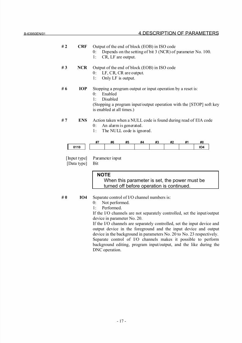
# 2 CRF Output of the end of block (EOB) in ISO code
0: Depends on the setting of bit 3 (NCR) of parameter No. 100.
1: CR, LF are output.
# 3 NCR Output of the end of block (EOB) in ISO code
0: LF, CR, CR are output.
1: Only LF is output.
# 6 IOP Stopping a program output or input operation by a reset is:
0: Enabled
1: Disabled
(Stopping a program input/output operation with the [STOP] soft key
is enabled at all times.)
# 7 ENS Action taken when a NULL code is found during read of EIA code0: An alarm is generated.
1: The NULL code is ignored.
#7 #6 #5 #4 #3 #2 #1 #0
0110 IO4
[Input type] Parameter input
[Data type] Bit
NOTE
When this parameter is set, the power must beturned off before operation is continued.
# 0 IO4 Separate control of I/O channel numbers is:
0: Not performed.
1: Performed.
If the I/O channels are not separately controlled, set the input/output
device in parameter No. 20.
If the I/O channels are separately controlled, set the input device and
output device in the foreground and the input device and output
device in the background in parameters No. 20 to No. 23 respectively.
Separate control of I/O channels makes it possible to perform background editing, program input/output, and the like during the
DNC operation.
8/21/2019 30i Parameter Manual
http://slidepdf.com/reader/full/30i-parameter-manual 30/493
4.DESCRIPTION OF PARAMETERS B-63950EN/01
- 18 -
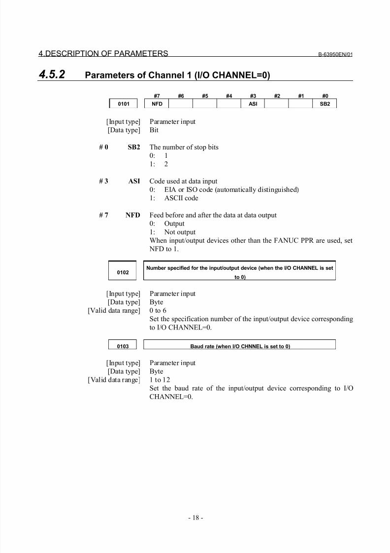
4.5.2 Parameters of Channel 1 (I/O CHANNEL=0)
#7 #6 #5 #4 #3 #2 #1 #00101 NFD ASI SB2
[Input type] Parameter input
[Data type] Bit
# 0 SB2 The number of stop bits
0: 1
1: 2
# 3 ASI Code used at data input
0: EIA or ISO code (automatically distinguished)
1: ASCII code
# 7 NFD Feed before and after the data at data output
0: Output
1: Not output
When input/output devices other than the FANUC PPR are used, set
NFD to 1.
0102Number specified for the input/output device (when the I/O CHANNEL is set
to 0)
[Input type] Parameter input
[Data type] Byte
[Valid data range] 0 to 6
Set the specification number of the input/output device corresponding
to I/O CHANNEL=0.
0103 Baud rate (when I/O CHNNEL is set to 0)
[Input type] Parameter input
[Data type] Byte
[Valid data range] 1 to 12
Set the baud rate of the input/output device corresponding to I/OCHANNEL=0.
8/21/2019 30i Parameter Manual
http://slidepdf.com/reader/full/30i-parameter-manual 31/493
B-63950EN/01 4.DESCRIPTION OF PARAMETERS
- 19 -
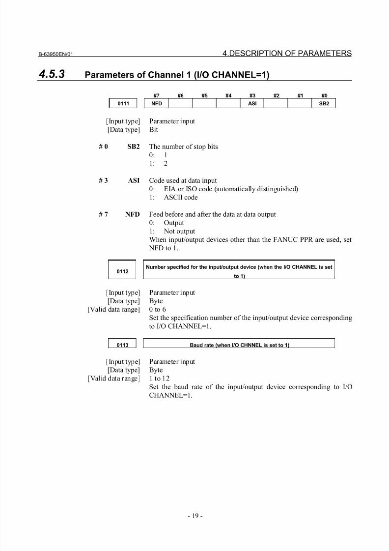
4.5.3 Parameters of Channel 1 (I/O CHANNEL=1)
#7 #6 #5 #4 #3 #2 #1 #00111 NFD ASI SB2
[Input type] Parameter input
[Data type] Bit
# 0 SB2 The number of stop bits
0: 1
1: 2
# 3 ASI Code used at data input
0: EIA or ISO code (automatically distinguished)
1: ASCII code
# 7 NFD Feed before and after the data at data output
0: Output
1: Not output
When input/output devices other than the FANUC PPR are used, set
NFD to 1.
0112Number specified for the input/output device (when the I/O CHANNEL is set
to 1)
[Input type] Parameter input
[Data type] Byte
[Valid data range] 0 to 6
Set the specification number of the input/output device corresponding
to I/O CHANNEL=1.
0113 Baud rate (when I/O CHNNEL is set to 1)
[Input type] Parameter input
[Data type] Byte
[Valid data range] 1 to 12
Set the baud rate of the input/output device corresponding to I/OCHANNEL=1.
8/21/2019 30i Parameter Manual
http://slidepdf.com/reader/full/30i-parameter-manual 32/493
4.DESCRIPTION OF PARAMETERS B-63950EN/01
- 20 -
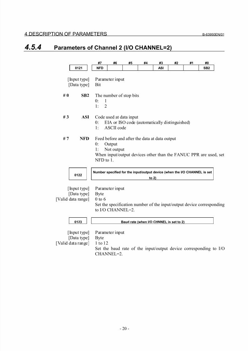
4.5.4 Parameters of Channel 2 (I/O CHANNEL=2)
#7 #6 #5 #4 #3 #2 #1 #0
0121 NFD ASI SB2
[Input type] Parameter input
[Data type] Bit
# 0 SB2 The number of stop bits
0: 1
1: 2
# 3 ASI Code used at data input
0: EIA or ISO code (automatically distinguished)1: ASCII code
# 7 NFD Feed before and after the data at data output
0: Output
1: Not output
When input/output devices other than the FANUC PPR are used, set
NFD to 1.
0122Number specified for the input/output device (when the I/O CHANNEL is set
to 2)
[Input type] Parameter input
[Data type] Byte
[Valid data range] 0 to 6
Set the specification number of the input/output device corresponding
to I/O CHANNEL=2.
0123 Baud rate (when I/O CHNNEL is set to 2)
[Input type] Parameter input
[Data type] Byte
[Valid data range] 1 to 12
Set the baud rate of the input/output device corresponding to I/O
CHANNEL=2.
8/21/2019 30i Parameter Manual
http://slidepdf.com/reader/full/30i-parameter-manual 33/493
B-63950EN/01 4.DESCRIPTION OF PARAMETERS
- 21 -
4.6 PARAMETERS RELATED TO SYSTEM CONFIGURATION
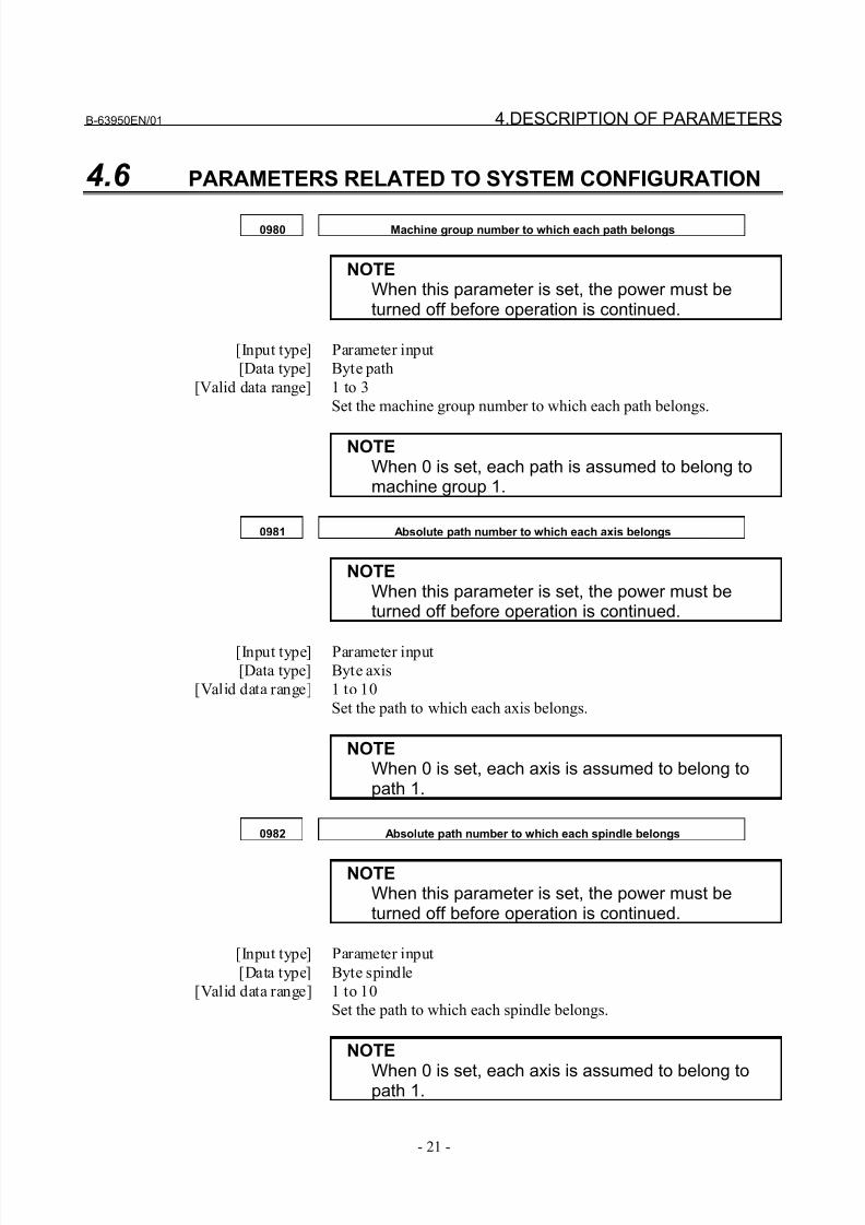
0980 Machine group number to which each path belongs
NOTEWhen this parameter is set, the power must beturned off before operation is continued.
[Input type] Parameter input
[Data type] Byte path
[Valid data range] 1 to 3
Set the machine group number to which each path belongs.
NOTEWhen 0 is set, each path is assumed to belong tomachine group 1.
0981 Absolute path number to which each axis belongs
NOTEWhen this parameter is set, the power must beturned off before operation is continued.
[Input type] Parameter input
[Data type] Byte axis
[Valid data range] 1 to 10
Set the path to which each axis belongs.
NOTEWhen 0 is set, each axis is assumed to belong topath 1.
0982 Absolute path number to which each spindle belongs
NOTEWhen this parameter is set, the power must beturned off before operation is continued.
[Input type] Parameter input
[Data type] Byte spindle
[Valid data range] 1 to 10
Set the path to which each spindle belongs.
NOTE
When 0 is set, each axis is assumed to belong topath 1.
8/21/2019 30i Parameter Manual
http://slidepdf.com/reader/full/30i-parameter-manual 34/493
4.DESCRIPTION OF PARAMETERS B-63950EN/01
- 22 -
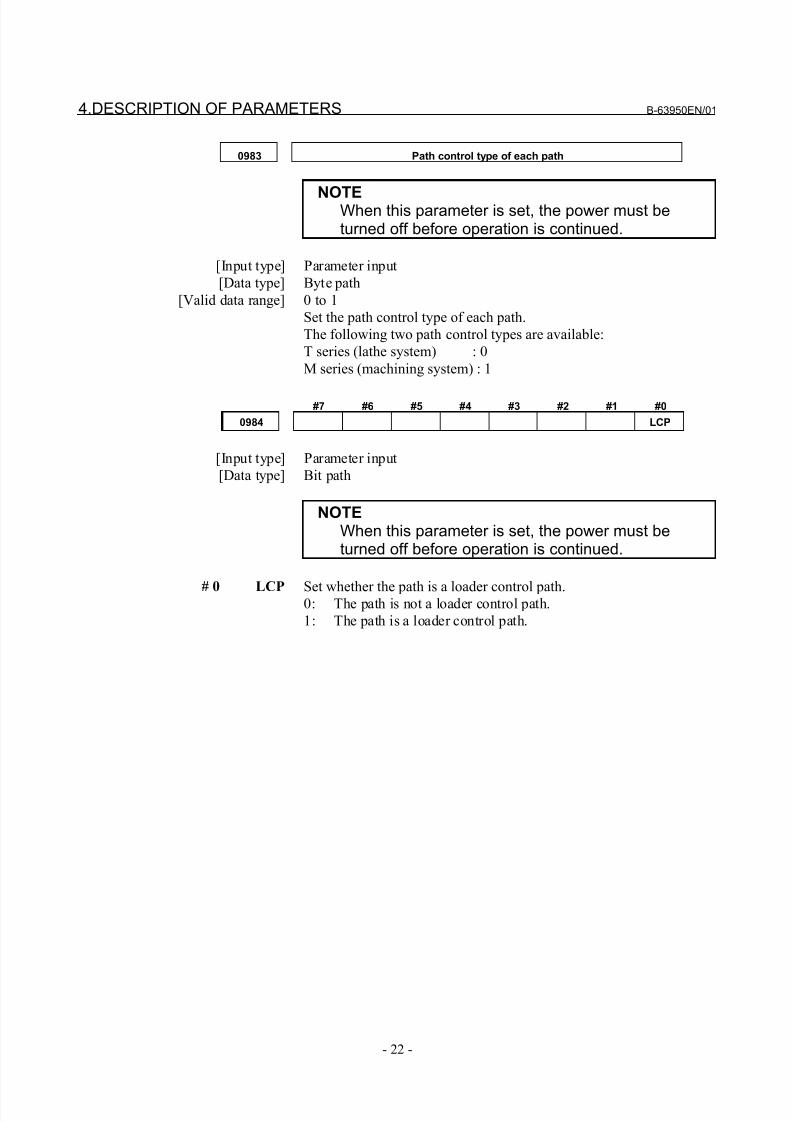
0983 Path control type of each path
NOTEWhen this parameter is set, the power must beturned off before operation is continued.
[Input type] Parameter input
[Data type] Byte path
[Valid data range] 0 to 1
Set the path control type of each path.
The following two path control types are available:
T series (lathe system) : 0
M series (machining system) : 1
#7 #6 #5 #4 #3 #2 #1 #0
0984 LCP
[Input type] Parameter input
[Data type] Bit path
NOTEWhen this parameter is set, the power must beturned off before operation is continued.
# 0 LCP Set whether the path is a loader control path.0: The path is not a loader control path.
1: The path is a loader control path.
8/21/2019 30i Parameter Manual
http://slidepdf.com/reader/full/30i-parameter-manual 35/493
B-63950EN/01 4.DESCRIPTION OF PARAMETERS
- 23 -
4.7 PARAMETERS OF AXIS CONTROL/INCREMENT SYSTEM
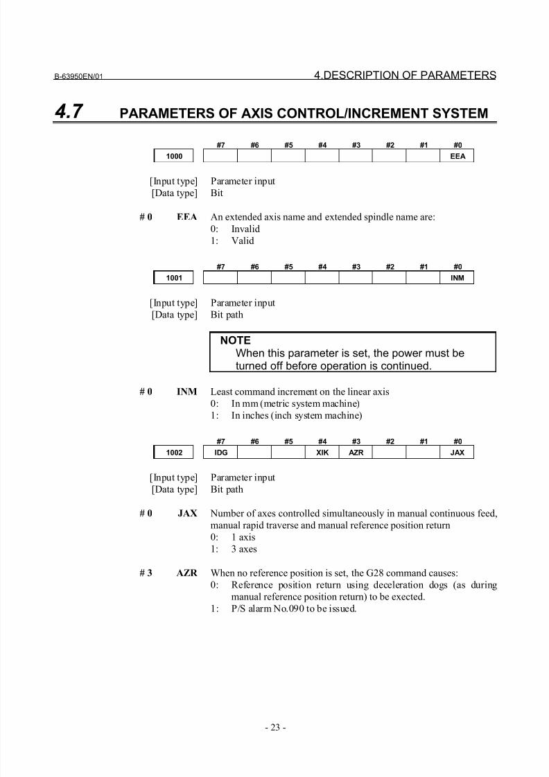
#7 #6 #5 #4 #3 #2 #1 #0
1000 EEA
[Input type] Parameter input
[Data type] Bit
# 0 EEA An extended axis name and extended spindle name are:
0: Invalid
1: Valid
#7 #6 #5 #4 #3 #2 #1 #0
1001 INM
[Input type] Parameter input
[Data type] Bit path
NOTEWhen this parameter is set, the power must beturned off before operation is continued.
# 0 INM Least command increment on the linear axis
0: In mm (metric system machine)1: In inches (inch system machine)
#7 #6 #5 #4 #3 #2 #1 #0
1002 IDG XIK AZR JAX
[Input type] Parameter input
[Data type] Bit path
# 0 JAX Number of axes controlled simultaneously in manual continuous feed,
manual rapid traverse and manual reference position return
0: 1 axis
1: 3 axes
# 3 AZR When no reference position is set, the G28 command causes:
0: Reference position return using deceleration dogs (as during
manual reference position return) to be exected.
1: P/S alarm No.090 to be issued.
8/21/2019 30i Parameter Manual
http://slidepdf.com/reader/full/30i-parameter-manual 36/493
4.DESCRIPTION OF PARAMETERS B-63950EN/01
- 24 -
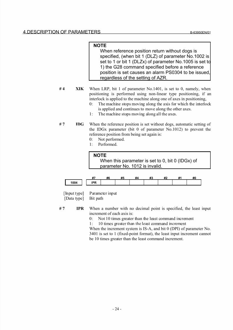
NOTEWhen reference position return without dogs is
specified, (when bit 1 (DLZ) of parameter No.1002 isset to 1 or bit 1 (DLZx) of parameter No.1005 is set to1) the G28 command specified before a referenceposition is set causes an alarm PS0304 to be issued,regardless of the setting of AZR.
# 4 XIK When LRP, bit 1 of parameter No.1401, is set to 0, namely, when
positioning is performed using non-linear type positioning, if an
interlock is applied to the machine along one of axes in positioning,
0: The machine stops moving along the axis for which the interlock
is applied and continues to move along the other axes.
1: The machine stops moving along all the axes.
# 7 IDG When the reference position is set without dogs, automatic setting of
the IDGx parameter (bit 0 of parameter No.1012) to prevent the
reference position from being set again is:
0: Not performed.
1: Performed.
NOTEWhen this parameter is set to 0, bit 0 (IDGx) of parameter No. 1012 is invalid.
#7 #6 #5 #4 #3 #2 #1 #0
1004 IPR
[Input type] Parameter input
[Data type] Bit path
# 7 IPR When a number with no decimal point is specified, the least input
increment of each axis is:
0: Not 10 times greater than the least command increment
1: 10 times greater than the least command increment
When the increment system is IS-A, and bit 0 (DPI) of parameter No.
3401 is set to 1 (fixed-point format), the least input increment cannot
be 10 times greater than the least command increment.
8/21/2019 30i Parameter Manual
http://slidepdf.com/reader/full/30i-parameter-manual 37/493
B-63950EN/01 4.DESCRIPTION OF PARAMETERS
- 25 -
#7 #6 #5 #4 #3 #2 #1 #0
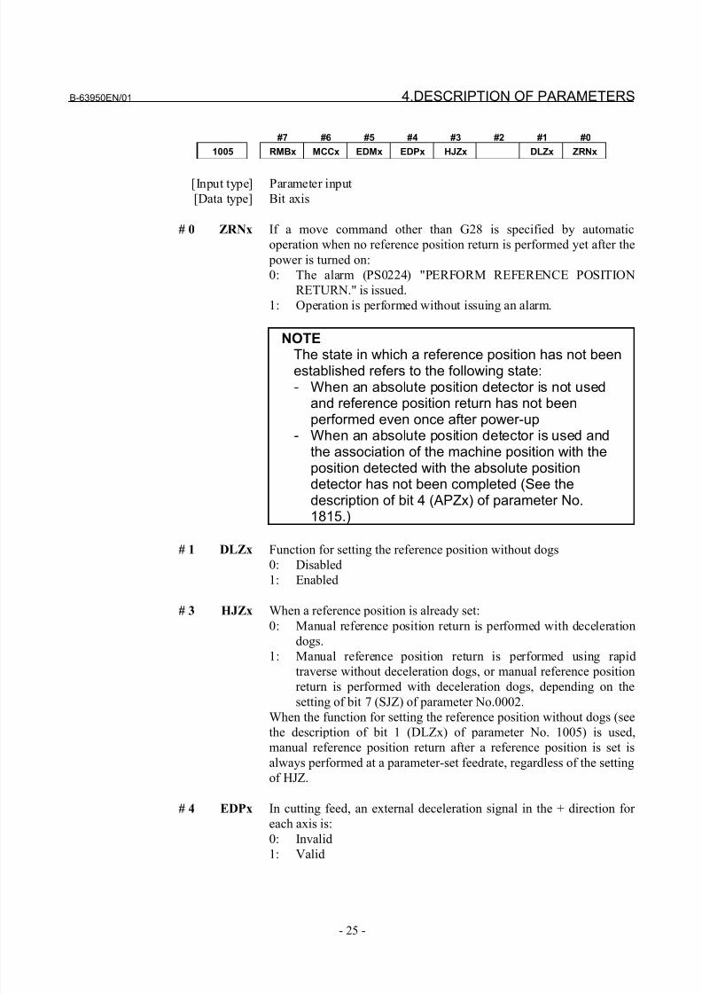
1005 RMBx MCCx EDMx EDPx HJZx DLZx ZRNx
[Input type] Parameter input
[Data type] Bit axis
# 0 ZRNx If a move command other than G28 is specified by automatic
operation when no reference position return is performed yet after the
power is turned on:
0: The alarm (PS0224) "PERFORM REFERENCE POSITION
RETURN." is issued.
1: Operation is performed without issuing an alarm.
NOTEThe state in which a reference position has not beenestablished refers to the following state:- When an absolute position detector is not used
and reference position return has not beenperformed even once after power-up
- When an absolute position detector is used andthe association of the machine position with theposition detected with the absolute positiondetector has not been completed (See thedescription of bit 4 (APZx) of parameter No.
1815.)
# 1 DLZx Function for setting the reference position without dogs
0: Disabled
1: Enabled
# 3 HJZx When a reference position is already set:
0: Manual reference position return is performed with deceleration
dogs.
1: Manual reference position return is performed using rapid
traverse without deceleration dogs, or manual reference position
return is performed with deceleration dogs, depending on the
setting of bit 7 (SJZ) of parameter No.0002.
When the function for setting the reference position without dogs (see
the description of bit 1 (DLZx) of parameter No. 1005) is used,
manual reference position return after a reference position is set is
always performed at a parameter-set feedrate, regardless of the setting
of HJZ.
# 4 EDPx In cutting feed, an external deceleration signal in the + direction for
each axis is:
0: Invalid
1: Valid
8/21/2019 30i Parameter Manual
http://slidepdf.com/reader/full/30i-parameter-manual 38/493
4.DESCRIPTION OF PARAMETERS B-63950EN/01
- 26 -
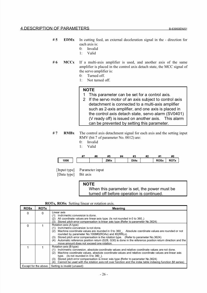
# 5 EDMx In cutting feed, an external deceleration signal in the - direction for
each axis is:
0: Invalid
1: Valid
# 6 MCCx If a multi-axis amplifier is used, and another axis of the same
amplifier is placed in the control axis detach state, the MCC signal of
the servo amplifier is:
0: Turned off.
1: Not turned off.
NOTE1 This parameter can be set for a control axis.2 If the servo motor of an axis subject to control axis
detachment is connected to a multi-axis amplifier such as 2-axis amplifier, and one axis is placed inthe control axis detach state, servo alarm (SV0401)(V ready off) is issued on another axis. This alarmcan be prevented by setting this parameter.
# 7 RMBx The control axis detachment signal for each axis and the setting input
RMV (bit 7 of parameter No. 0012) are:
0: Invalid
1: Valid
#7 #6 #5 #4 #3 #2 #1 #0
1006 ZMIx DIAx ROSx ROTx
[Input type] Parameter input
[Data type] Bit axis
NOTEWhen this parameter is set, the power must beturned off before operation is continued.
ROTx, ROSxSetting linear or rotation axis.ROSx ROTx Meaning
0 0 Linear axis(1) Inch/metric conversion is done.(2) All coordinate values are linear axis type. (Is not rounded in 0 to 360_)(3) Stored pitch error compensation is linear axis type (Refer to parameter No.3624)
0 1 Rotation axis (A type)(1) Inch/metric conversion is not done.(2) Machine coordinate values are rounded in 0 to 360_. Absolute coordinate values are rounded or not
rounded by parameter No.1008#0(ROAx) and #2(RRLx).(3) Stored pitch error compensation is the rotation type. (Refer to parameter No.3624)(4) Automatic reference position return (G28, G30) is done in the reference position return direction and the
move amount does not exceed one rotation.
1 1 Rotation axis (B type)(1) Inch/metric conversion, absolute coordinate values and relative coordinate values are not done.(2) Machine coordinate values, absolute coordinate values and relative coordinate values are linear axis
type. (Is not rounded in 0 to 360_).(3) Stored pitch error compensation is linear axis type (Refer to parameter No.3624)(4) Cannot be used with the rotation axis roll over function and the index table indexing function (M series)
Except for the above. Setting is invalid (unused)
8/21/2019 30i Parameter Manual
http://slidepdf.com/reader/full/30i-parameter-manual 39/493
B-63950EN/01 4.DESCRIPTION OF PARAMETERS
- 27 -
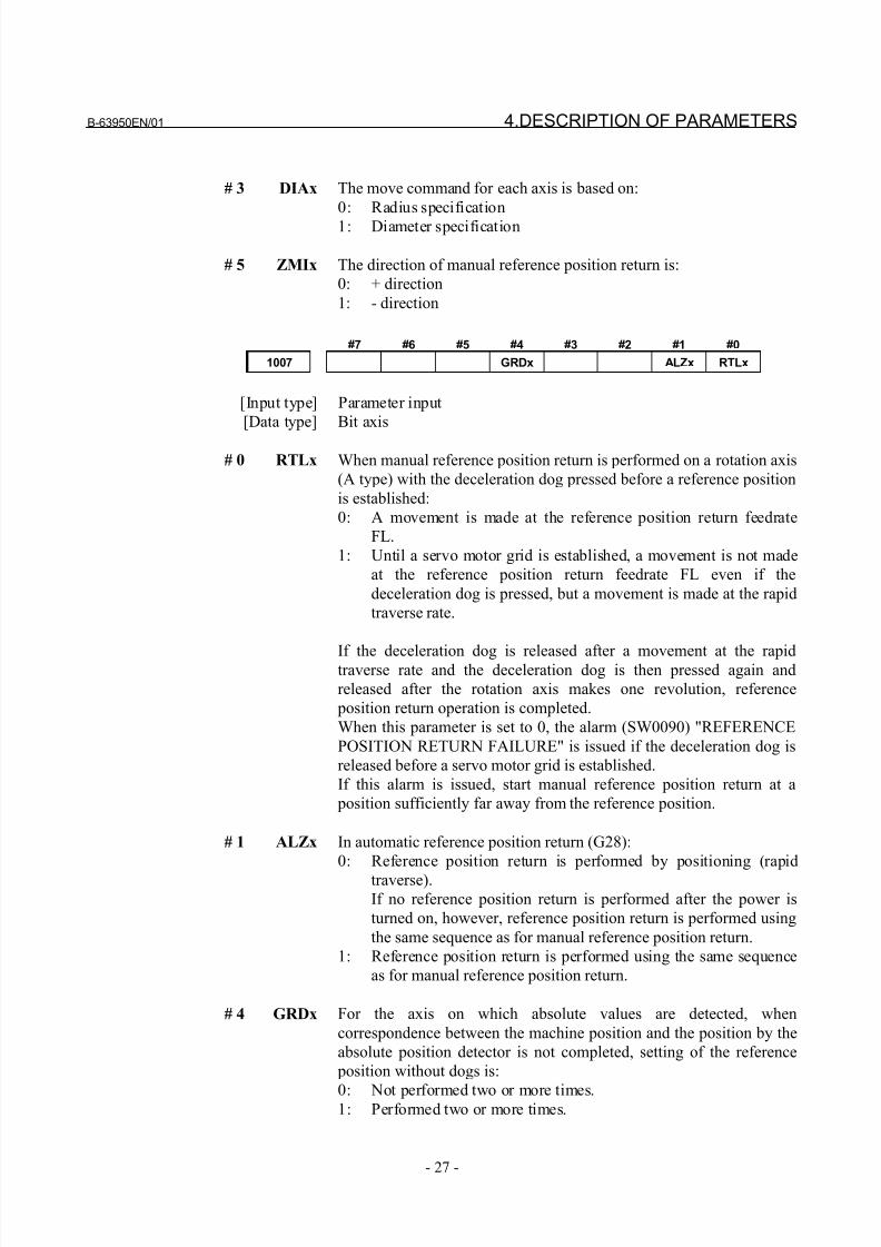
# 3 DIAx The move command for each axis is based on:
0: Radius specification
1: Diameter specification
# 5 ZMIx The direction of manual reference position return is:
0: + direction
1: - direction
#7 #6 #5 #4 #3 #2 #1 #0
1007 GRDx ALZx RTLx
[Input type] Parameter input
[Data type] Bit axis
# 0 RTLx When manual reference position return is performed on a rotation axis
(A type) with the deceleration dog pressed before a reference position
is established:
0: A movement is made at the reference position return feedrate
FL.
1: Until a servo motor grid is established, a movement is not made
at the reference position return feedrate FL even if the
deceleration dog is pressed, but a movement is made at the rapid
traverse rate.
If the deceleration dog is released after a movement at the rapidtraverse rate and the deceleration dog is then pressed again and
released after the rotation axis makes one revolution, reference
position return operation is completed.
When this parameter is set to 0, the alarm (SW0090) "REFERENCE
POSITION RETURN FAILURE" is issued if the deceleration dog is
released before a servo motor grid is established.
If this alarm is issued, start manual reference position return at a
position sufficiently far away from the reference position.
# 1 ALZx In automatic reference position return (G28):
0: Reference position return is performed by positioning (rapid
traverse).If no reference position return is performed after the power is
turned on, however, reference position return is performed using
the same sequence as for manual reference position return.
1: Reference position return is performed using the same sequence
as for manual reference position return.
# 4 GRDx For the axis on which absolute values are detected, when
correspondence between the machine position and the position by the
absolute position detector is not completed, setting of the reference
position without dogs is:
0: Not performed two or more times.1: Performed two or more times.
8/21/2019 30i Parameter Manual
http://slidepdf.com/reader/full/30i-parameter-manual 40/493
4.DESCRIPTION OF PARAMETERS B-63950EN/01
- 28 -
#7 #6 #5 #4 #3 #2 #1 #0
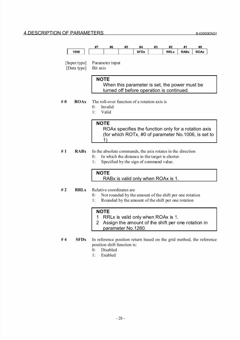
1008 SFDx RRLx RABx ROAx
[Input type] Parameter input
[Data type] Bit axis
NOTEWhen this parameter is set, the power must beturned off before operation is continued.
# 0 ROAx The roll-over function of a rotation axis is
0: Invalid
1: Valid
NOTEROAx specifies the function only for a rotation axis(for which ROTx, #0 of parameter No.1006, is set to1)
# 1 RABx In the absolute commands, the axis rotates in the direction
0: In which the distance to the target is shorter.
1: Specified by the sign of command value.
NOTE
RABx is valid only when ROAx is 1.
# 2 RRLx Relative coordinates are
0: Not rounded by the amount of the shift per one rotation
1: Rounded by the amount of the shift per one rotation
NOTE1 RRLx is valid only when ROAx is 1.2 Assign the amount of the shift per one rotation in
parameter No.1260.
# 4 SFDx In reference position return based on the grid method, the reference position shift function is:
0: Disabled
1: Enabled
8/21/2019 30i Parameter Manual
http://slidepdf.com/reader/full/30i-parameter-manual 41/493
B-63950EN/01 4.DESCRIPTION OF PARAMETERS
- 29 -
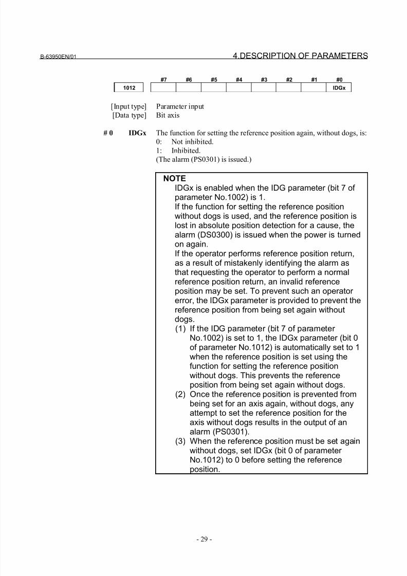
#7 #6 #5 #4 #3 #2 #1 #0
1012 IDGx
[Input type] Parameter input
[Data type] Bit axis
# 0 IDGx The function for setting the reference position again, without dogs, is:
0: Not inhibited.
1: Inhibited.
(The alarm (PS0301) is issued.)
NOTEIDGx is enabled when the IDG parameter (bit 7 of parameter No.1002) is 1.If the function for setting the reference positionwithout dogs is used, and the reference position islost in absolute position detection for a cause, thealarm (DS0300) is issued when the power is turnedon again.If the operator performs reference position return,as a result of mistakenly identifying the alarm asthat requesting the operator to perform a normalreference position return, an invalid referenceposition may be set. To prevent such an operator
error, the IDGx parameter is provided to prevent thereference position from being set again withoutdogs.(1) If the IDG parameter (bit 7 of parameter
No.1002) is set to 1, the IDGx parameter (bit 0of parameter No.1012) is automatically set to 1when the reference position is set using thefunction for setting the reference positionwithout dogs. This prevents the referenceposition from being set again without dogs.
(2) Once the reference position is prevented from
being set for an axis again, without dogs, anyattempt to set the reference position for theaxis without dogs results in the output of analarm (PS0301).
(3) When the reference position must be set againwithout dogs, set IDGx (bit 0 of parameter No.1012) to 0 before setting the referenceposition.
8/21/2019 30i Parameter Manual
http://slidepdf.com/reader/full/30i-parameter-manual 42/493
4.DESCRIPTION OF PARAMETERS B-63950EN/01
- 30 -
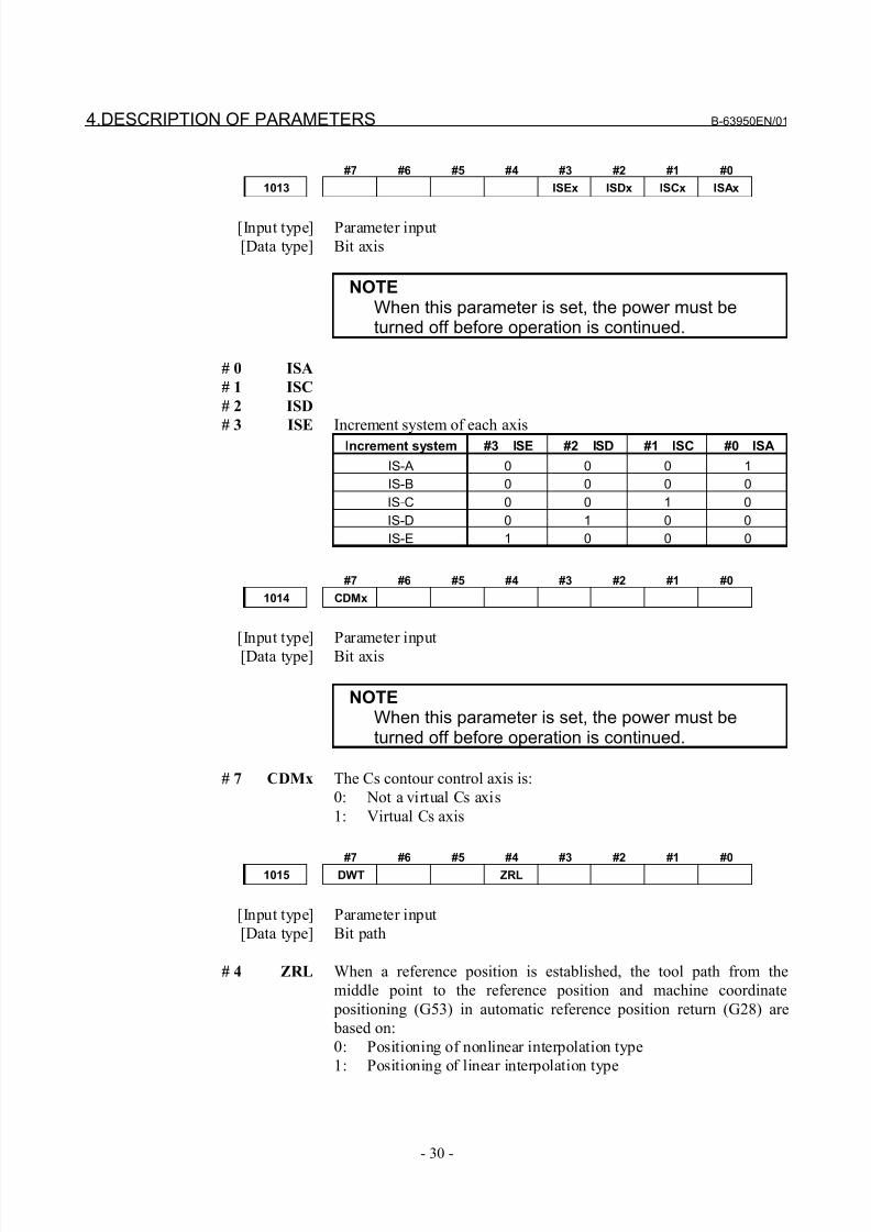
#7 #6 #5 #4 #3 #2 #1 #0
1013 ISEx ISDx ISCx ISAx
[Input type] Parameter input
[Data type] Bit axis
NOTEWhen this parameter is set, the power must beturned off before operation is continued.
# 0 ISA
# 1 ISC
# 2 ISD
# 3 ISE Increment system of each axisIncrement system #3 ISE #2 ISD #1 ISC #0 ISA
IS-A 0 0 0 1
IS-B 0 0 0 0
IS-C 0 0 1 0
IS-D 0 1 0 0
IS-E 1 0 0 0
#7 #6 #5 #4 #3 #2 #1 #0
1014 CDMx
[Input type] Parameter input
[Data type] Bit axis
NOTEWhen this parameter is set, the power must beturned off before operation is continued.
# 7 CDMx The Cs contour control axis is:
0: Not a virtual Cs axis
1: Virtual Cs axis
#7 #6 #5 #4 #3 #2 #1 #01015 DWT ZRL
[Input type] Parameter input
[Data type] Bit path
# 4 ZRL When a reference position is established, the tool path from the
middle point to the reference position and machine coordinate
positioning (G53) in automatic reference position return (G28) are
based on:
0: Positioning of nonlinear interpolation type
1: Positioning of linear interpolation type
8/21/2019 30i Parameter Manual
http://slidepdf.com/reader/full/30i-parameter-manual 43/493
B-63950EN/01 4.DESCRIPTION OF PARAMETERS
- 31 -
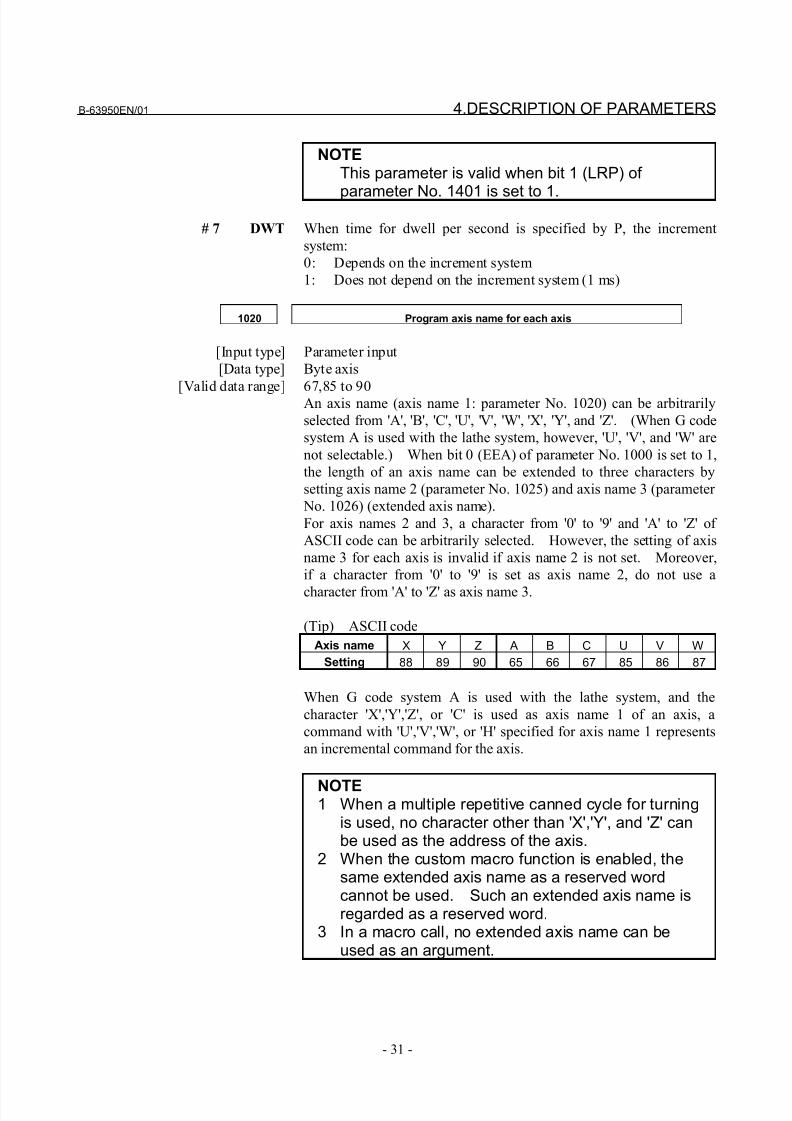
NOTEThis parameter is valid when bit 1 (LRP) of
parameter No. 1401 is set to 1.
# 7 DWT When time for dwell per second is specified by P, the increment
system:
0: Depends on the increment system
1: Does not depend on the increment system (1 ms)
1020 Program axis name for each axis
[Input type] Parameter input
[Data type] Byte axis
[Valid data range] 67,85 to 90An axis name (axis name 1: parameter No. 1020) can be arbitrarily
selected from 'A', 'B', 'C', 'U', 'V', 'W', 'X', 'Y', and 'Z'. (When G code
system A is used with the lathe system, however, 'U', 'V', and 'W' are
not selectable.) When bit 0 (EEA) of parameter No. 1000 is set to 1,
the length of an axis name can be extended to three characters by
setting axis name 2 (parameter No. 1025) and axis name 3 (parameter
No. 1026) (extended axis name).
For axis names 2 and 3, a character from '0' to '9' and 'A' to 'Z' of
ASCII code can be arbitrarily selected. However, the setting of axis
name 3 for each axis is invalid if axis name 2 is not set. Moreover,
if a character from '0' to '9' is set as axis name 2, do not use a
character from 'A' to 'Z' as axis name 3.
(Tip) ASCII code
Axis name X Y Z A B C U V W
Setting 88 89 90 65 66 67 85 86 87
When G code system A is used with the lathe system, and the
character 'X','Y','Z', or 'C' is used as axis name 1 of an axis, a
command with 'U','V','W', or 'H' specified for axis name 1 represents
an incremental command for the axis.
NOTE1 When a multiple repetitive canned cycle for turning
is used, no character other than 'X','Y', and 'Z' canbe used as the address of the axis.
2 When the custom macro function is enabled, thesame extended axis name as a reserved wordcannot be used. Such an extended axis name isregarded as a reserved word.
3 In a macro call, no extended axis name can beused as an argument.
8/21/2019 30i Parameter Manual
http://slidepdf.com/reader/full/30i-parameter-manual 44/493
4.DESCRIPTION OF PARAMETERS B-63950EN/01
- 32 -
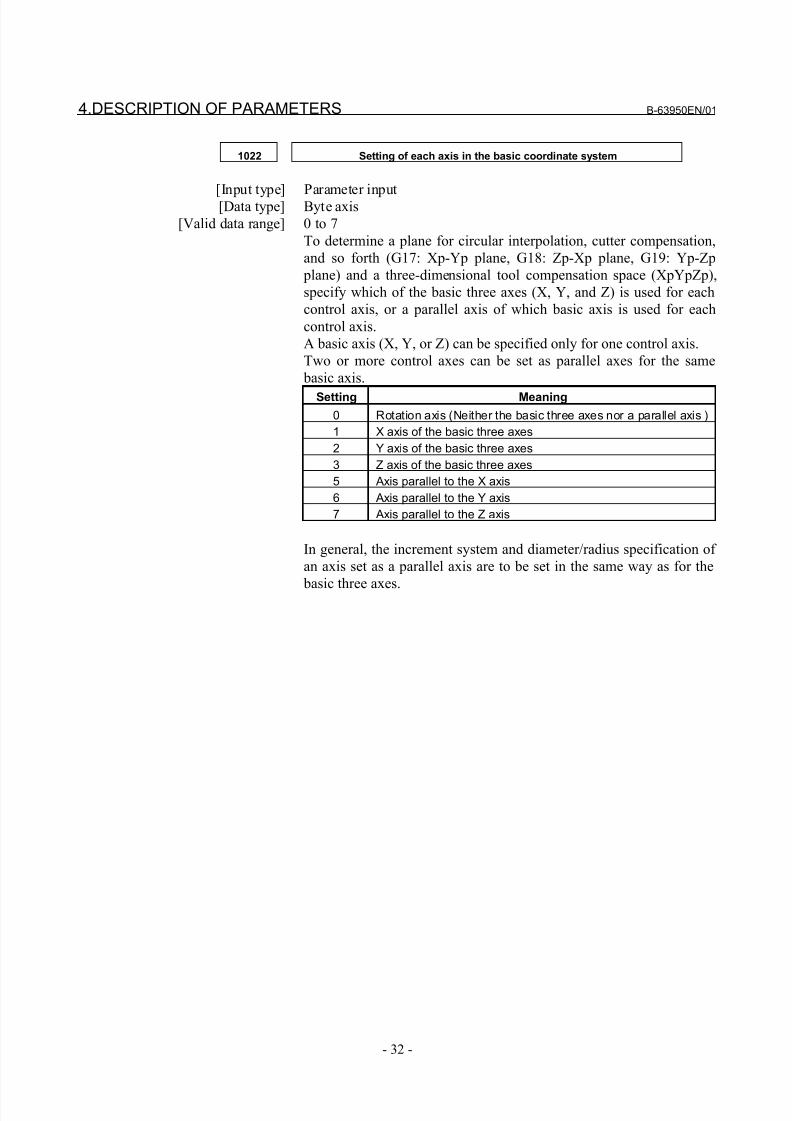
1022 Setting of each axis in the basic coordinate system
[Input type] Parameter input[Data type] Byte axis
[Valid data range] 0 to 7
To determine a plane for circular interpolation, cutter compensation,
and so forth (G17: Xp-Yp plane, G18: Zp-Xp plane, G19: Yp-Zp
plane) and a three-dimensional tool compensation space (XpYpZp),
specify which of the basic three axes (X, Y, and Z) is used for each
control axis, or a parallel axis of which basic axis is used for each
control axis.
A basic axis (X, Y, or Z) can be specified only for one control axis.
Two or more control axes can be set as parallel axes for the same
basic axis.
Setting Meaning
0 Rotation axis (Neither the basic three axes nor a parallel axis )
1 X axis of the basic three axes
2 Y axis of the basic three axes
3 Z axis of the basic three axes
5 Axis parallel to the X axis
6 Axis parallel to the Y axis
7 Axis parallel to the Z axis
In general, the increment system and diameter/radius specification of
an axis set as a parallel axis are to be set in the same way as for the
basic three axes.
8/21/2019 30i Parameter Manual
http://slidepdf.com/reader/full/30i-parameter-manual 45/493
B-63950EN/01 4.DESCRIPTION OF PARAMETERS
- 33 -
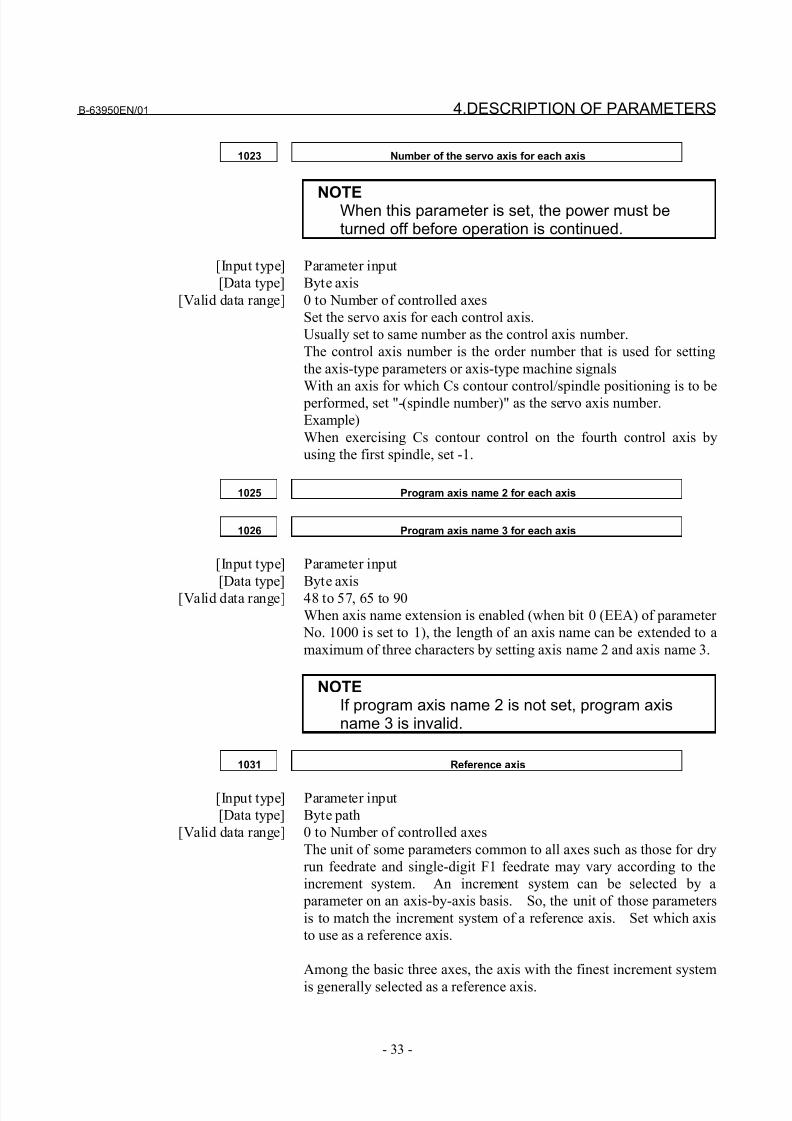
1023 Number of the servo axis for each axis
NOTEWhen this parameter is set, the power must beturned off before operation is continued.
[Input type] Parameter input
[Data type] Byte axis
[Valid data range] 0 to Number of controlled axes
Set the servo axis for each control axis.
Usually set to same number as the control axis number.
The control axis number is the order number that is used for setting
the axis-type parameters or axis-type machine signals
With an axis for which Cs contour control/spindle positioning is to be performed, set "-(spindle number)" as the servo axis number.
Example)
When exercising Cs contour control on the fourth control axis by
using the first spindle, set -1.
1025 Program axis name 2 for each axis
1026 Program axis name 3 for each axis
[Input type] Parameter input
[Data type] Byte axis
[Valid data range] 48 to 57, 65 to 90
When axis name extension is enabled (when bit 0 (EEA) of parameter
No. 1000 is set to 1), the length of an axis name can be extended to a
maximum of three characters by setting axis name 2 and axis name 3.
NOTEIf program axis name 2 is not set, program axisname 3 is invalid.
1031 Reference axis
[Input type] Parameter input
[Data type] Byte path
[Valid data range] 0 to Number of controlled axes
The unit of some parameters common to all axes such as those for dry
run feedrate and single-digit F1 feedrate may vary according to the
increment system. An increment system can be selected by a
parameter on an axis-by-axis basis. So, the unit of those parameters
is to match the increment system of a reference axis. Set which axis
to use as a reference axis.
Among the basic three axes, the axis with the finest increment system
is generally selected as a reference axis.
8/21/2019 30i Parameter Manual
http://slidepdf.com/reader/full/30i-parameter-manual 46/493
4.DESCRIPTION OF PARAMETERS B-63950EN/01
- 34 -
4.8 PARAMETERS OF COORDINATES
#7 #6 #5 #4 #3 #2 #1 #0
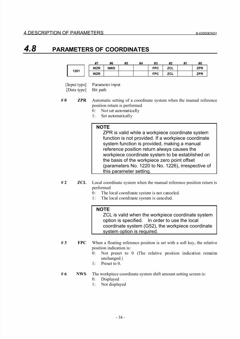
WZR NWS FPC ZCL ZPR1201
WZR FPC ZCL ZPR
[Input type] Parameter input
[Data type] Bit path
# 0 ZPR Automatic setting of a coordinate system when the manual reference
position return is performed
0: Not set automatically
1: Set automatically
NOTEZPR is valid while a workpiece coordinate systemfunction is not provided. If a workpiece coordinatesystem function is provided, making a manualreference position return always causes theworkpiece coordinate system to be established onthe basis of the workpiece zero point offset(parameters No. 1220 to No. 1226), irrespective of this parameter setting.
# 2 ZCL Local coordinate system when the manual reference position return is
performed
0: The local coordinate system is not canceled.
1: The local coordinate system is canceled.
NOTEZCL is valid when the workpiece coordinate systemoption is specified. In order to use the localcoordinate system (G52), the workpiece coordinatesystem option is required.
# 3 FPC When a floating reference position is set with a soft key, the relative
position indication is:
0: Not preset to 0 (The relative position indication remains
unchanged.)
1: Preset to 0.
# 6 NWS The workpiece coordinate system shift amount setting screen is:
0: Displayed
1: Not displayed
8/21/2019 30i Parameter Manual
http://slidepdf.com/reader/full/30i-parameter-manual 47/493
B-63950EN/01 4.DESCRIPTION OF PARAMETERS
- 35 -
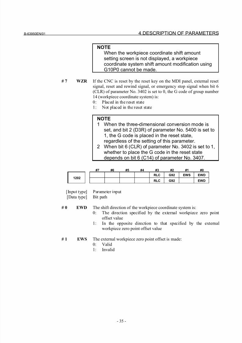
NOTEWhen the workpiece coordinate shift amount
setting screen is not displayed, a workpiececoordinate system shift amount modification usingG10P0 cannot be made.
# 7 WZR If the CNC is reset by the reset key on the MDI panel, external reset
signal, reset and rewind signal, or emergency stop signal when bit 6
(CLR) of parameter No. 3402 is set to 0, the G code of group number
14 (workpiece coordinate system) is:
0: Placed in the reset state
1: Not placed in the reset state
NOTE1 When the three-dimensional conversion mode isset, and bit 2 (D3R) of parameter No. 5400 is set to1, the G code is placed in the reset state,regardless of the setting of this parameter.
2 When bit 6 (CLR) of parameter No. 3402 is set to 1,whether to place the G code in the reset statedepends on bit 6 (C14) of parameter No. 3407.
#7 #6 #5 #4 #3 #2 #1 #0
RLC G92 EWS EWD1202
RLC G92 EWD
[Input type] Parameter input
[Data type] Bit path
# 0 EWD The shift direction of the workpiece coordinate system is:
0: The direction specified by the external workpiece zero point
offset value
1: In the opposite direction to that specified by the external
workpiece zero point offset value
# 1 EWS The external workpiece zero point offset is made:0: Valid
1: Invalid
8/21/2019 30i Parameter Manual
http://slidepdf.com/reader/full/30i-parameter-manual 48/493
4.DESCRIPTION OF PARAMETERS B-63950EN/01
- 36 -
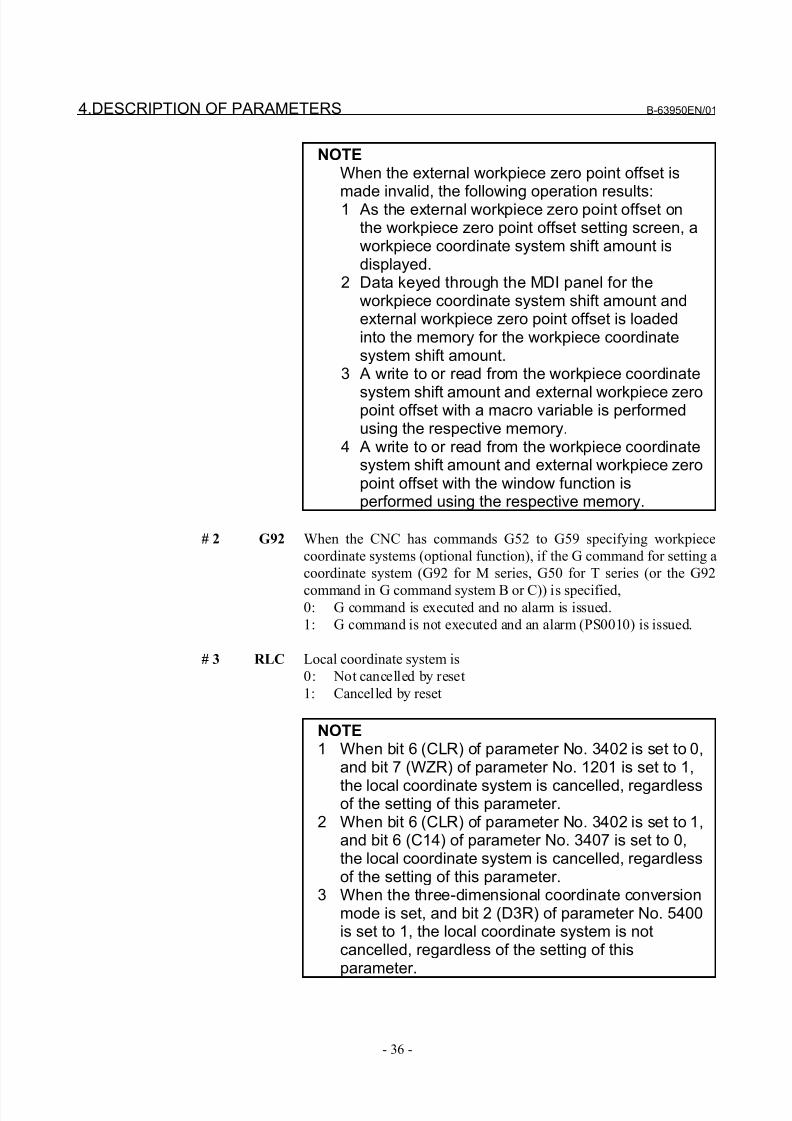
NOTEWhen the external workpiece zero point offset is
made invalid, the following operation results:1 As the external workpiece zero point offset onthe workpiece zero point offset setting screen, aworkpiece coordinate system shift amount isdisplayed.
2 Data keyed through the MDI panel for theworkpiece coordinate system shift amount andexternal workpiece zero point offset is loadedinto the memory for the workpiece coordinatesystem shift amount.
3 A write to or read from the workpiece coordinate
system shift amount and external workpiece zeropoint offset with a macro variable is performedusing the respective memory.
4 A write to or read from the workpiece coordinatesystem shift amount and external workpiece zeropoint offset with the window function isperformed using the respective memory.
# 2 G92 When the CNC has commands G52 to G59 specifying workpiece
coordinate systems (optional function), if the G command for setting a
coordinate system (G92 for M series, G50 for T series (or the G92
command in G command system B or C)) is specified,0: G command is executed and no alarm is issued.
1: G command is not executed and an alarm (PS0010) is issued.
# 3 RLC Local coordinate system is
0: Not cancelled by reset
1: Cancelled by reset
NOTE1 When bit 6 (CLR) of parameter No. 3402 is set to 0,
and bit 7 (WZR) of parameter No. 1201 is set to 1,
the local coordinate system is cancelled, regardlessof the setting of this parameter.
2 When bit 6 (CLR) of parameter No. 3402 is set to 1,and bit 6 (C14) of parameter No. 3407 is set to 0,the local coordinate system is cancelled, regardlessof the setting of this parameter.
3 When the three-dimensional coordinate conversionmode is set, and bit 2 (D3R) of parameter No. 5400is set to 1, the local coordinate system is notcancelled, regardless of the setting of thisparameter.
8/21/2019 30i Parameter Manual
http://slidepdf.com/reader/full/30i-parameter-manual 49/493
B-63950EN/01 4.DESCRIPTION OF PARAMETERS
- 37 -
1220 External workpiece zero point offset value in each axis
[Input type] Setting input[Data type] Real axis
[Unit of data] mm, inch, degree (input unit)
[Minimum unit of data] Depend on the increment system of the applied axis
[Valid data range] 9 digit of minimum unit of data (refer to standard parameter setting
table (A) )
(When the increment system is IS-B, -999999.999 to +999999.999)
This is one of the parameters that give the position of the zero point of
workpiece coordinate system (G54 to G59). It gives an offset of the
workpiece zero point common to all workpiece coordinate systems. In
general, the offset varies depending on the workpiece coordinate
systems. The value can be set from the PMC using the external data
input function.
1221 Workpiece zero point offset value in workpiece coordinate system 1 (G54)
1222 Workpiece zero point offset value in workpiece coordinate system 2(G55)
1223 Workpiece zero point offset value in workpiece coordinate system 3(G56)
1224 Workpiece zero point offset value in workpiece coordinate system 4 (G57)
1225 Workpiece zero point offset value in workpiece coordinate system 5 (G58)
1226 Workpiece zero point offset value in workpiece coordinate system 6 (G59)
[Input type] Setting input
[Data type] Real axis
[Unit of data] mm, inch, degree (input unit)
[Minimum unit of data] Depend on the increment system of the applied axis
[Valid data range] 9 digit of minimum unit of data (refer to standard parameter setting
table (A) )
(When the increment system is IS-B, -999999.999 to +999999.999)
The workpiece zero point offset values in workpiece coordinate
systems 1 to 6 (G54 to G59) are set.
8/21/2019 30i Parameter Manual
http://slidepdf.com/reader/full/30i-parameter-manual 50/493
4.DESCRIPTION OF PARAMETERS B-63950EN/01
- 38 -
1240 Coordinate value of the reference position in the machine coordinate system
NOTEWhen this parameter is set, the power must beturned off before operation is continued.
[Input type] Parameter input
[Data type] Real axis
[Unit of data] mm, inch, degree (machine unit)
[Minimum unit of data] Depend on the increment system of the applied axis
[Valid data range] 9 digit of minimum unit of data (refer to standard parameter setting
table (A) )
(When the increment system is IS-B, -999999.999 to +999999.999)
Set the coordinate values of the reference position in the machinecoordinate system.
1241Coordinate value of the second reference position in the machine coordinate
system
[Input type] Parameter input
[Data type] Real axis
[Unit of data] mm, inch, degree (machine unit)
[Minimum unit of data] Depend on the increment system of the applied axis
[Valid data range] 9 digit of minimum unit of data (refer to standard parameter setting
table (A) )
(When the increment system is IS-B, -999999.999 to +999999.999)
Set the coordinate values of the second reference position in the
machine coordinate system.
1242Coordinate value of the third reference position in the machine coordinate
system
[Input type] Parameter input
[Data type] Real axis
[Unit of data] mm, inch, degree (machine unit)
[Minimum unit of data] Depend on the increment system of the applied axis
[Valid data range] 9 digit of minimum unit of data (refer to standard parameter settingtable (A) )
(When the increment system is IS-B, -999999.999 to +999999.999)
Set the coordinate values of the third reference position in the
machine coordinate system.
8/21/2019 30i Parameter Manual
http://slidepdf.com/reader/full/30i-parameter-manual 51/493
B-63950EN/01 4.DESCRIPTION OF PARAMETERS
- 39 -
1243Coordinate value of the fourth reference position in the machine coordinate
system
[Input type] Parameter input
[Data type] Real axis
[Unit of data] mm, inch, degree (machine unit)
[Minimum unit of data] Depend on the increment system of the applied axis
[Valid data range] 9 digit of minimum unit of data (refer to standard parameter setting
table (A) )
(When the increment system is IS-B, -999999.999 to +999999.999)
Set the coordinate values of the fourth reference position in the
machine coordinate system.
1244
Coordinate value of the floating reference position in the machine
coordinate system
[Input type] Parameter input
[Data type] Real axis
[Unit of data] mm, inch, degree (machine unit)
[Minimum unit of data] Depend on the increment system of the applied axis
[Valid data range] 9 digit of minimum unit of data (refer to standard parameter setting
table (A) )
(When the increment system is IS-B, -999999.999 to +999999.999)
Set the coordinate values of the floating reference position in the
machine coordinate system.
1250Coordinate system of the reference position used when automatic
coordinate system setting is performed
[Input type] Parameter input
[Data type] Real axis
[Unit of data] mm, inch, degree (input unit)
[Minimum unit of data] Depend on the increment system of the applied axis
[Valid data range] 9 digit of minimum unit of data (refer to standard parameter setting
table (A) )
(When the increment system is IS-B, -999999.999 to +999999.999)
Set the coordinate system of the reference position on each axis to beused for setting a coordinate system automatically.
8/21/2019 30i Parameter Manual
http://slidepdf.com/reader/full/30i-parameter-manual 52/493
4.DESCRIPTION OF PARAMETERS B-63950EN/01
- 40 -
1260 Amount of a shift per one rotation of a rotation axis
NOTEWhen this parameter is set, the power must beturned off before operation is continued.
[Input type] Parameter input
[Data type] Real axis
[Unit of data] Degree
[Minimum unit of data] Depend on the increment system of the applied axis
[Valid data range] 0 or positive 9 digit of minimum unit of data (refer to the standard
parameter setting table (B) )
(When the increment system is IS-B, 0.0 to +999999.999)
Set the amount of a shift per one rotaion of a rotaion axis.For the rotation axis used for cylindrical interpolation, set the
standard value.
Distance between two opposite tool posts in mirror image1290
[Input type] Parameter input
[Data type] Real path
[Unit of data] mm, inch (input unit)
[Minimum unit of data] Depend on the increment system of the reference axis
[Valid data range] 0 or positive 9 digit of minimum unit of data (refer to the standard
parameter setting table (B) )
(When the increment system is IS-B, 0.0 to +999999.999)
Set the distance between two opposite tool posts in mirror image.
8/21/2019 30i Parameter Manual
http://slidepdf.com/reader/full/30i-parameter-manual 53/493
B-63950EN/01 4.DESCRIPTION OF PARAMETERS
- 41 -
4.9 PARAMETERS OF STORED STROKE CHECK
#7 #6 #5 #4 #3 #2 #1 #0
1300 BFA RL3 LMS OUT
[Input type] Setting input
[Data type] Bit path
# 0 OUT The area inside or outside of the stored stroke check 2 is set as an
inhibition area
0: Inside
1: Outside
# 2 LMS The EXLM signal for switching stored stroke check
0: Disabled
1: Enabled
When bit 0 (DLM) of parameter No. 1301 is set to 1, the stored stroke
check 1 switch signal EXLM (G007#6) is made invalid.
# 5 RL3 Stored stroke check 3 release signal RLSOT3 is
0: Disabled
1: Enabled
# 7 BFA When the stored stroke check 1, 2, or 3 alarm is issued, an
interference alarm is issued with the inter-path interference check function (T series), or a chuck/tail stock barrier (T series) alarm is
issued:
0: The tool stops after entering the prohibited area.
1: The tool stops before the prohibited area.
#7 #6 #5 #4 #3 #2 #1 #0
1301 PLC NPC DLM
[Input type] Setting input
[Data type] Bit path
# 0 DLM The stored stroke limit switching signals +EXLx and -EXLx for each
axial direction are:
0: Disabled.
1: Enabled.
When this parameter is set to 1, the stored stroke check 1 switch
signal EXLM (G007#6) is made invalid.
# 2 NPC As part of the stroke limit check performed before movement, the
movement specified in G31 (skip) and G37 (automatic tool length
measurement) blocks is:
0: Checked
1: Not checked
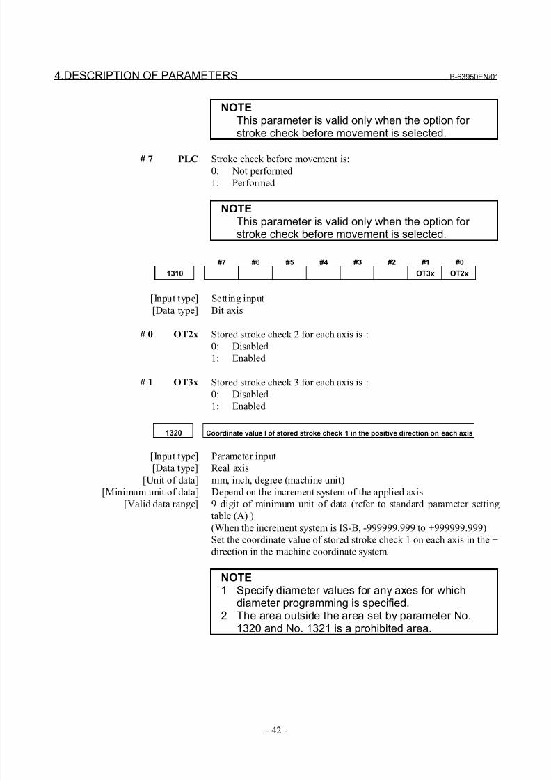
8/21/2019 30i Parameter Manual
http://slidepdf.com/reader/full/30i-parameter-manual 54/493
4.DESCRIPTION OF PARAMETERS B-63950EN/01
- 42 -
NOTEThis parameter is valid only when the option for
stroke check before movement is selected.
# 7 PLC Stroke check before movement is:
0: Not performed
1: Performed
NOTEThis parameter is valid only when the option for stroke check before movement is selected.
#7 #6 #5 #4 #3 #2 #1 #0
1310 OT3x OT2x
[Input type] Setting input
[Data type] Bit axis
# 0 OT2x Stored stroke check 2 for each axis is :
0: Disabled
1: Enabled
# 1 OT3x Stored stroke check 3 for each axis is :
0: Disabled
1: Enabled
1320 Coordinate value I of stored stroke check 1 in the positive direction on each axis
[Input type] Parameter input
[Data type] Real axis
[Unit of data] mm, inch, degree (machine unit)
[Minimum unit of data] Depend on the increment system of the applied axis
[Valid data range] 9 digit of minimum unit of data (refer to standard parameter setting
table (A) )
(When the increment system is IS-B, -999999.999 to +999999.999)
Set the coordinate value of stored stroke check 1 on each axis in the +
direction in the machine coordinate system.
NOTE1 Specify diameter values for any axes for which
diameter programming is specified.2 The area outside the area set by parameter No.
1320 and No. 1321 is a prohibited area.
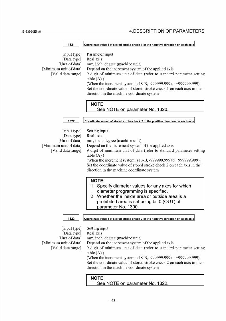
8/21/2019 30i Parameter Manual
http://slidepdf.com/reader/full/30i-parameter-manual 55/493
B-63950EN/01 4.DESCRIPTION OF PARAMETERS
- 43 -
1321 Coordinate value I of stored stroke check 1 in the negative direction on each axis
[Input type] Parameter input[Data type] Real axis
[Unit of data] mm, inch, degree (machine unit)
[Minimum unit of data] Depend on the increment system of the applied axis
[Valid data range] 9 digit of minimum unit of data (refer to standard parameter setting
table (A) )
(When the increment system is IS-B, -999999.999 to +999999.999)
Set the coordinate value of stored stroke check 1 on each axis in the -
direction in the machine coordinate system.
NOTESee NOTE on parameter No. 1320.
1322 Coordinate value I of stored stroke check 2 in the positive direction on each axis
[Input type] Setting input
[Data type] Real axis
[Unit of data] mm, inch, degree (machine unit)
[Minimum unit of data] Depend on the increment system of the applied axis
[Valid data range] 9 digit of minimum unit of data (refer to standard parameter setting
table (A) )
(When the increment system is IS-B, -999999.999 to +999999.999)
Set the coordinate value of stored stroke check 2 on each axis in the +
direction in the machine coordinate system.
NOTE1 Specify diameter values for any axes for which
diameter programming is specified.2 Whether the inside area or outside area is a
prohibited area is set using bit 0 (OUT) of parameter No. 1300.
1323 Coordinate value I of stored stroke check 2 in the negative direction on each axis
[Input type] Setting input
[Data type] Real axis
[Unit of data] mm, inch, degree (machine unit)
[Minimum unit of data] Depend on the increment system of the applied axis
[Valid data range] 9 digit of minimum unit of data (refer to standard parameter setting
table (A) )
(When the increment system is IS-B, -999999.999 to +999999.999)
Set the coordinate value of stored stroke check 2 on each axis in the -
direction in the machine coordinate system.
NOTESee NOTE on parameter No. 1322.
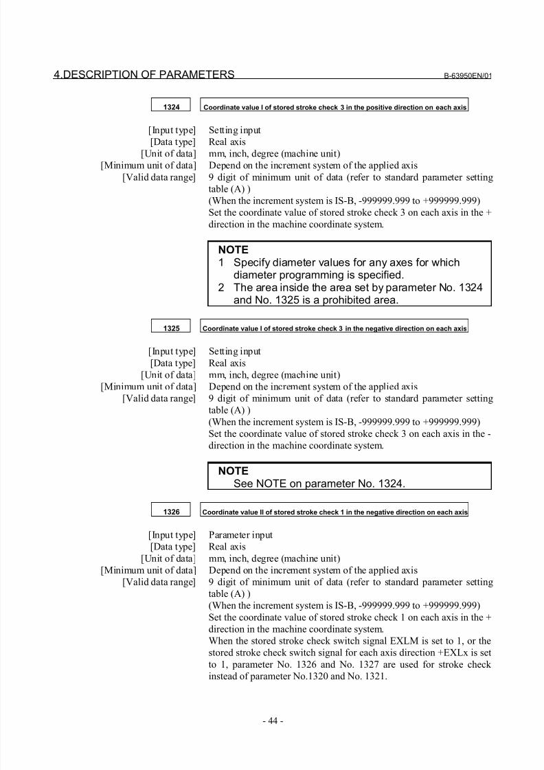
8/21/2019 30i Parameter Manual
http://slidepdf.com/reader/full/30i-parameter-manual 56/493
4.DESCRIPTION OF PARAMETERS B-63950EN/01
- 44 -
1324 Coordinate value I of stored stroke check 3 in the positive direction on each axis
[Input type] Setting input[Data type] Real axis
[Unit of data] mm, inch, degree (machine unit)
[Minimum unit of data] Depend on the increment system of the applied axis
[Valid data range] 9 digit of minimum unit of data (refer to standard parameter setting
table (A) )
(When the increment system is IS-B, -999999.999 to +999999.999)
Set the coordinate value of stored stroke check 3 on each axis in the +
direction in the machine coordinate system.
NOTE1 Specify diameter values for any axes for which
diameter programming is specified.2 The area inside the area set by parameter No. 1324
and No. 1325 is a prohibited area.
1325 Coordinate value I of stored stroke check 3 in the negative direction on each axis
[Input type] Setting input
[Data type] Real axis
[Unit of data] mm, inch, degree (machine unit)
[Minimum unit of data] Depend on the increment system of the applied axis
[Valid data range] 9 digit of minimum unit of data (refer to standard parameter setting
table (A) )
(When the increment system is IS-B, -999999.999 to +999999.999)
Set the coordinate value of stored stroke check 3 on each axis in the -
direction in the machine coordinate system.
NOTESee NOTE on parameter No. 1324.
1326 Coordinate value II of stored stroke check 1 in the negative direction on each axis
[Input type] Parameter input[Data type] Real axis
[Unit of data] mm, inch, degree (machine unit)
[Minimum unit of data] Depend on the increment system of the applied axis
[Valid data range] 9 digit of minimum unit of data (refer to standard parameter setting
table (A) )
(When the increment system is IS-B, -999999.999 to +999999.999)
Set the coordinate value of stored stroke check 1 on each axis in the +
direction in the machine coordinate system.
When the stored stroke check switch signal EXLM is set to 1, or the
stored stroke check switch signal for each axis direction +EXLx is set
to 1, parameter No. 1326 and No. 1327 are used for stroke check
instead of parameter No.1320 and No. 1321.
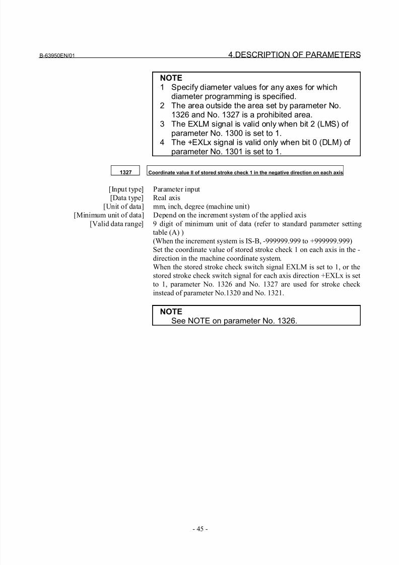
8/21/2019 30i Parameter Manual
http://slidepdf.com/reader/full/30i-parameter-manual 57/493
B-63950EN/01 4.DESCRIPTION OF PARAMETERS
- 45 -
NOTE1 Specify diameter values for any axes for which
diameter programming is specified.2 The area outside the area set by parameter No.1326 and No. 1327 is a prohibited area.
3 The EXLM signal is valid only when bit 2 (LMS) of parameter No. 1300 is set to 1.
4 The +EXLx signal is valid only when bit 0 (DLM) of parameter No. 1301 is set to 1.
1327 Coordinate value II of stored stroke check 1 in the negative direction on each axis
[Input type] Parameter input
[Data type] Real axis[Unit of data] mm, inch, degree (machine unit)
[Minimum unit of data] Depend on the increment system of the applied axis
[Valid data range] 9 digit of minimum unit of data (refer to standard parameter setting
table (A) )
(When the increment system is IS-B, -999999.999 to +999999.999)
Set the coordinate value of stored stroke check 1 on each axis in the -
direction in the machine coordinate system.
When the stored stroke check switch signal EXLM is set to 1, or the
stored stroke check switch signal for each axis direction +EXLx is set
to 1, parameter No. 1326 and No. 1327 are used for stroke check
instead of parameter No.1320 and No. 1321.
NOTESee NOTE on parameter No. 1326.
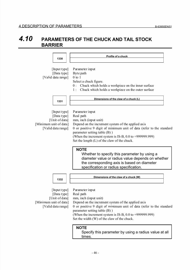
8/21/2019 30i Parameter Manual
http://slidepdf.com/reader/full/30i-parameter-manual 58/493
4.DESCRIPTION OF PARAMETERS B-63950EN/01
- 46 -
4.10 PARAMETERS OF THE CHUCK AND TAIL STOCK
BARRIER
Profile of a chuck1330
[Input type] Parameter input
[Data type] Byte path
[Valid data range] 0 to 1
Select a chuck figure.
0 : Chuck which holds a workpiece on the inner surface
1 : Chuck which holds a workpiece on the outer surface
Dimensions of the claw of a chuck (L)1331
[Input type] Parameter input
[Data type] Real path
[Unit of data] mm, inch (input unit)
[Minimum unit of data] Depend on the increment system of the applied axis
[Valid data range] 0 or positive 9 digit of minimum unit of data (refer to the standard
parameter setting table (B) )
(When the increment system is IS-B, 0.0 to +999999.999)
Set the length (L) of the claw of the chuck.
NOTEWhether to specify this parameter by using adiameter value or radius value depends on whether the corresponding axis is based on diameter specification or radius specification.
Dimensions of the claw of a chuck (W)1332
[Input type] Parameter input[Data type] Real path
[Unit of data] mm, inch (input unit)
[Minimum unit of data] Depend on the increment system of the applied axis
[Valid data range] 0 or positive 9 digit of minimum unit of data (refer to the standard
parameter setting table (B) )
(When the increment system is IS-B, 0.0 to +999999.999)
Set the width (W) of the claw of the chuck.
NOTESpecify this parameter by using a radius value at all
times.
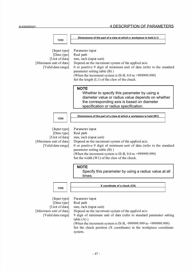
8/21/2019 30i Parameter Manual
http://slidepdf.com/reader/full/30i-parameter-manual 59/493
B-63950EN/01 4.DESCRIPTION OF PARAMETERS
- 47 -
Dimensions of the part of a claw at which a workpiece is held (L1)1333
[Input type] Parameter input
[Data type] Real path
[Unit of data] mm, inch (input unit)
[Minimum unit of data] Depend on the increment system of the applied axis
[Valid data range] 0 or positive 9 digit of minimum unit of data (refer to the standard
parameter setting table (B) )
(When the increment system is IS-B, 0.0 to +999999.999)
Set the length (L1) of the claw of the chuck.
NOTE
Whether to specify this parameter by using adiameter value or radius value depends on whether the corresponding axis is based on diameter specification or radius specification.
Dimensions of the part of a claw at which a workpiece is held (W1)1334
[Input type] Parameter input
[Data type] Real path
[Unit of data] mm, inch (input unit)
[Minimum unit of data] Depend on the increment system of the applied axis[Valid data range] 0 or positive 9 digit of minimum unit of data (refer to the standard
parameter setting table (B) )
(When the increment system is IS-B, 0.0 to +999999.999)
Set the width (W1) of the claw of the chuck.
NOTESpecify this parameter by using a radius value at alltimes.
X coordinate of a chuck (CX)1335
[Input type] Parameter input
[Data type] Real path
[Unit of data] mm, inch (input unit)
[Minimum unit of data] Depend on the increment system of the applied axis
[Valid data range] 9 digit of minimum unit of data (refer to standard parameter setting
table (A) )
(When the increment system is IS-B, -999999.999 to +999999.999)
Set the chuck position (X coordinate) in the workpiece coordinate
system.
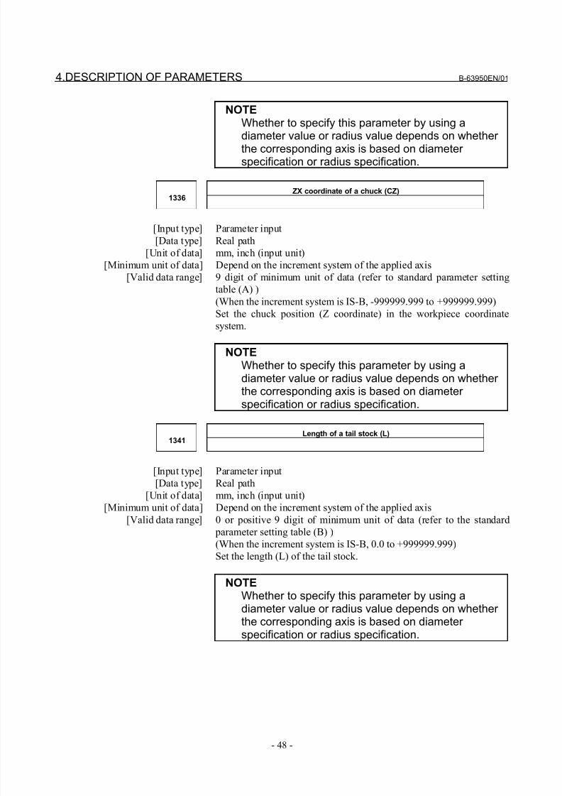
8/21/2019 30i Parameter Manual
http://slidepdf.com/reader/full/30i-parameter-manual 60/493
4.DESCRIPTION OF PARAMETERS B-63950EN/01
- 48 -
NOTEWhether to specify this parameter by using a
diameter value or radius value depends on whether the corresponding axis is based on diameter specification or radius specification.
ZX coordinate of a chuck (CZ)1336
[Input type] Parameter input
[Data type] Real path
[Unit of data] mm, inch (input unit)
[Minimum unit of data] Depend on the increment system of the applied axis
[Valid data range] 9 digit of minimum unit of data (refer to standard parameter settingtable (A) )
(When the increment system is IS-B, -999999.999 to +999999.999)
Set the chuck position (Z coordinate) in the workpiece coordinate
system.
NOTEWhether to specify this parameter by using adiameter value or radius value depends on whether the corresponding axis is based on diameter specification or radius specification.
Length of a tail stock (L)1341
[Input type] Parameter input
[Data type] Real path
[Unit of data] mm, inch (input unit)
[Minimum unit of data] Depend on the increment system of the applied axis
[Valid data range] 0 or positive 9 digit of minimum unit of data (refer to the standard
parameter setting table (B) )
(When the increment system is IS-B, 0.0 to +999999.999)
Set the length (L) of the tail stock.
NOTEWhether to specify this parameter by using adiameter value or radius value depends on whether the corresponding axis is based on diameter specification or radius specification.
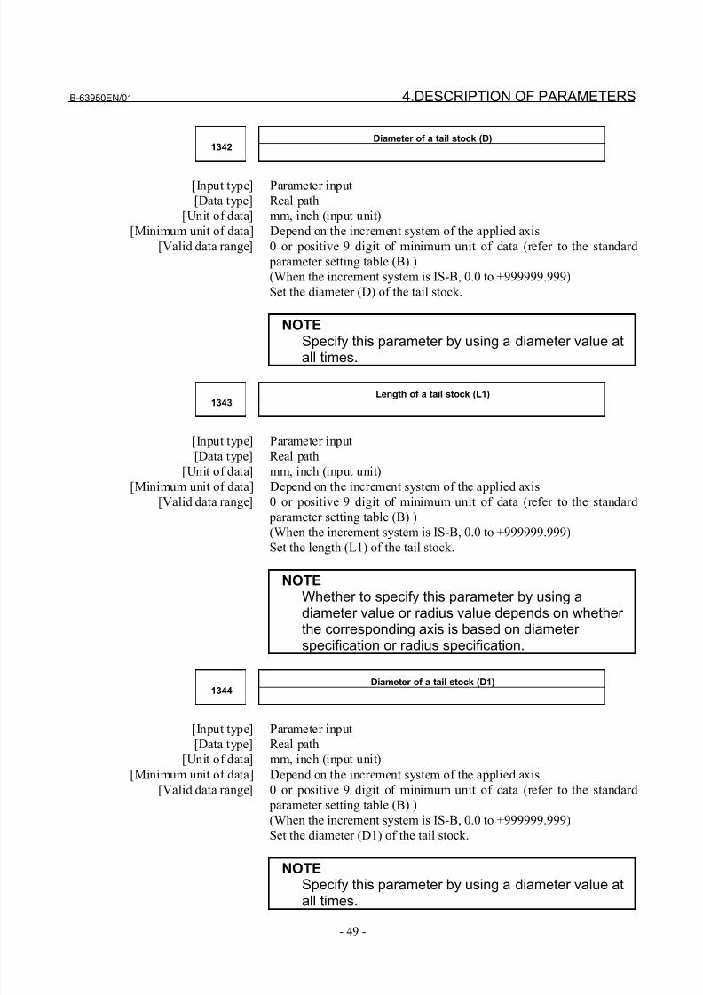
8/21/2019 30i Parameter Manual
http://slidepdf.com/reader/full/30i-parameter-manual 61/493
B-63950EN/01 4.DESCRIPTION OF PARAMETERS
- 49 -
Diameter of a tail stock (D)1342
[Input type] Parameter input
[Data type] Real path
[Unit of data] mm, inch (input unit)
[Minimum unit of data] Depend on the increment system of the applied axis
[Valid data range] 0 or positive 9 digit of minimum unit of data (refer to the standard
parameter setting table (B) )
(When the increment system is IS-B, 0.0 to +999999.999)
Set the diameter (D) of the tail stock.
NOTE
Specify this parameter by using a diameter value atall times.
Length of a tail stock (L1)1343
[Input type] Parameter input
[Data type] Real path
[Unit of data] mm, inch (input unit)
[Minimum unit of data] Depend on the increment system of the applied axis
[Valid data range] 0 or positive 9 digit of minimum unit of data (refer to the standard
parameter setting table (B) )(When the increment system is IS-B, 0.0 to +999999.999)
Set the length (L1) of the tail stock.
NOTEWhether to specify this parameter by using adiameter value or radius value depends on whether the corresponding axis is based on diameter specification or radius specification.
Diameter of a tail stock (D1)1344
[Input type] Parameter input
[Data type] Real path
[Unit of data] mm, inch (input unit)
[Minimum unit of data] Depend on the increment system of the applied axis
[Valid data range] 0 or positive 9 digit of minimum unit of data (refer to the standard
parameter setting table (B) )
(When the increment system is IS-B, 0.0 to +999999.999)
Set the diameter (D1) of the tail stock.
NOTESpecify this parameter by using a diameter value atall times.
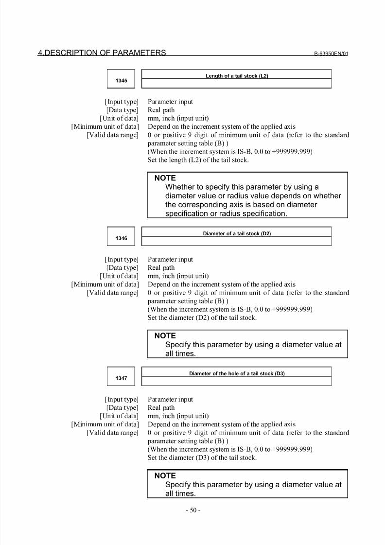
8/21/2019 30i Parameter Manual
http://slidepdf.com/reader/full/30i-parameter-manual 62/493
4.DESCRIPTION OF PARAMETERS B-63950EN/01
- 50 -
Length of a tail stock (L2)1345
[Input type] Parameter input
[Data type] Real path
[Unit of data] mm, inch (input unit)
[Minimum unit of data] Depend on the increment system of the applied axis
[Valid data range] 0 or positive 9 digit of minimum unit of data (refer to the standard
parameter setting table (B) )
(When the increment system is IS-B, 0.0 to +999999.999)
Set the length (L2) of the tail stock.
NOTE
Whether to specify this parameter by using adiameter value or radius value depends on whether the corresponding axis is based on diameter specification or radius specification.
Diameter of a tail stock (D2)1346
[Input type] Parameter input
[Data type] Real path
[Unit of data] mm, inch (input unit)
[Minimum unit of data] Depend on the increment system of the applied axis[Valid data range] 0 or positive 9 digit of minimum unit of data (refer to the standard
parameter setting table (B) )
(When the increment system is IS-B, 0.0 to +999999.999)
Set the diameter (D2) of the tail stock.
NOTESpecify this parameter by using a diameter value atall times.
Diameter of the hole of a tail stock (D3)1347
[Input type] Parameter input
[Data type] Real path
[Unit of data] mm, inch (input unit)
[Minimum unit of data] Depend on the increment system of the applied axis
[Valid data range] 0 or positive 9 digit of minimum unit of data (refer to the standard
parameter setting table (B) )
(When the increment system is IS-B, 0.0 to +999999.999)
Set the diameter (D3) of the tail stock.
NOTESpecify this parameter by using a diameter value atall times.
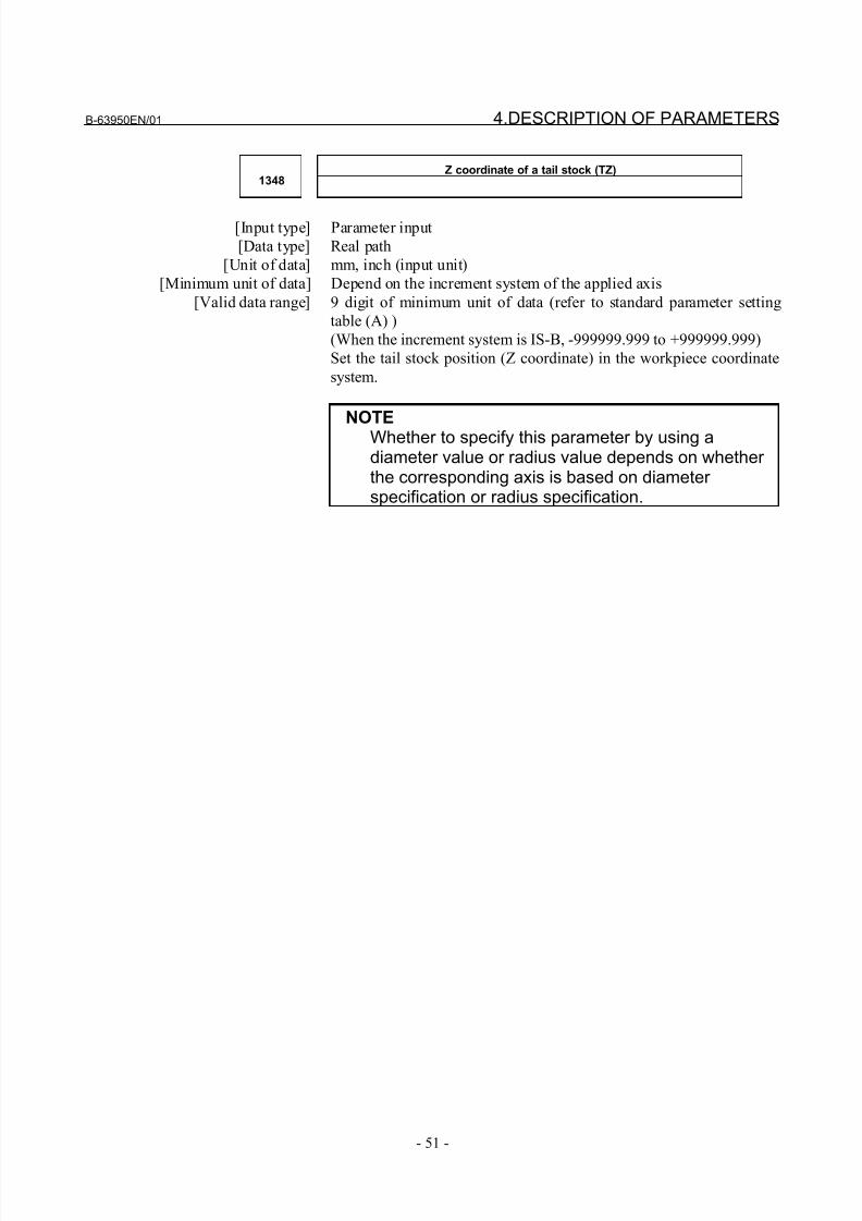
8/21/2019 30i Parameter Manual
http://slidepdf.com/reader/full/30i-parameter-manual 63/493
B-63950EN/01 4.DESCRIPTION OF PARAMETERS
- 51 -
Z coordinate of a tail stock (TZ)1348
[Input type] Parameter input
[Data type] Real path
[Unit of data] mm, inch (input unit)
[Minimum unit of data] Depend on the increment system of the applied axis
[Valid data range] 9 digit of minimum unit of data (refer to standard parameter setting
table (A) )
(When the increment system is IS-B, -999999.999 to +999999.999)
Set the tail stock position (Z coordinate) in the workpiece coordinate
system.
NOTEWhether to specify this parameter by using adiameter value or radius value depends on whether the corresponding axis is based on diameter specification or radius specification.
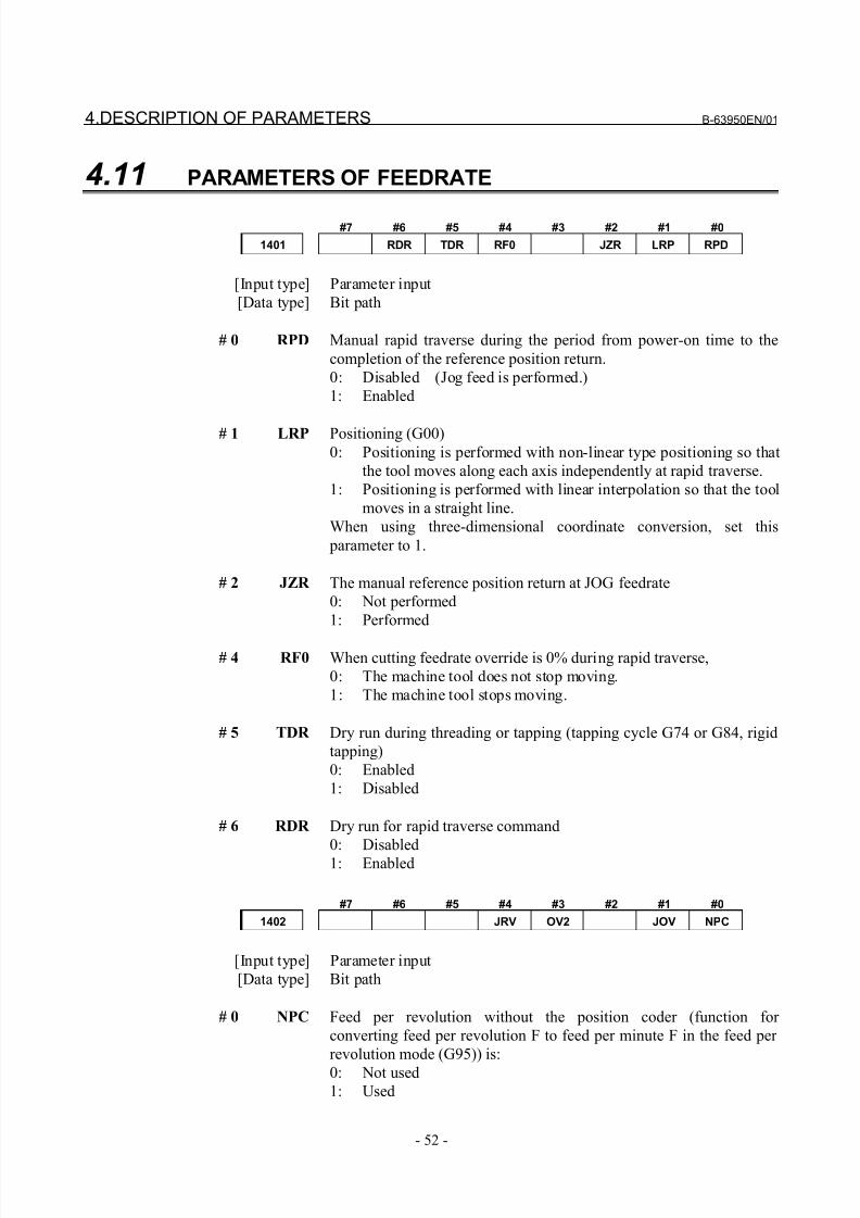
8/21/2019 30i Parameter Manual
http://slidepdf.com/reader/full/30i-parameter-manual 64/493
4.DESCRIPTION OF PARAMETERS B-63950EN/01
- 52 -
4.11 PARAMETERS OF FEEDRATE
#7 #6 #5 #4 #3 #2 #1 #0
1401 RDR TDR RF0 JZR LRP RPD
[Input type] Parameter input
[Data type] Bit path
# 0 RPD Manual rapid traverse during the period from power-on time to the
completion of the reference position return.
0: Disabled (Jog feed is performed.)
1: Enabled
# 1 LRP Positioning (G00)
0: Positioning is performed with non-linear type positioning so that
the tool moves along each axis independently at rapid traverse.
1: Positioning is performed with linear interpolation so that the tool
moves in a straight line.
When using three-dimensional coordinate conversion, set this
parameter to 1.
# 2 JZR The manual reference position return at JOG feedrate
0: Not performed
1: Performed
# 4 RF0 When cutting feedrate override is 0% during rapid traverse,
0: The machine tool does not stop moving.
1: The machine tool stops moving.
# 5 TDR Dry run during threading or tapping (tapping cycle G74 or G84, rigid
tapping)
0: Enabled
1: Disabled
# 6 RDR Dry run for rapid traverse command
0: Disabled
1: Enabled
#7 #6 #5 #4 #3 #2 #1 #0
1402 JRV OV2 JOV NPC
[Input type] Parameter input
[Data type] Bit path
# 0 NPC Feed per revolution without the position coder (function for
converting feed per revolution F to feed per minute F in the feed per
revolution mode (G95)) is:
0: Not used1: Used
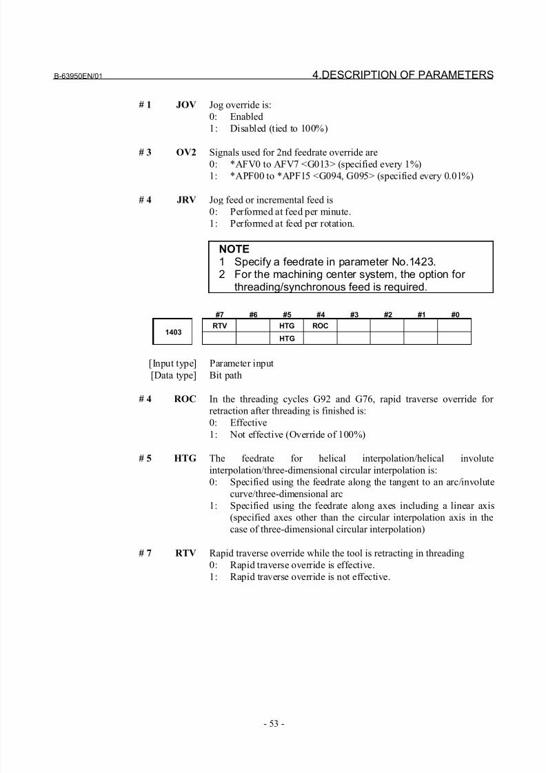
8/21/2019 30i Parameter Manual
http://slidepdf.com/reader/full/30i-parameter-manual 65/493
B-63950EN/01 4.DESCRIPTION OF PARAMETERS
- 53 -
# 1 JOV Jog override is:
0: Enabled
1: Disabled (tied to 100%)
# 3 OV2 Signals used for 2nd feedrate override are
0: *AFV0 to AFV7 <G013> (specified every 1%)
1: *APF00 to *APF15 <G094, G095> (specified every 0.01%)
# 4 JRV Jog feed or incremental feed is
0: Performed at feed per minute.
1: Performed at feed per rotation.
NOTE1 Specify a feedrate in parameter No.1423.
2 For the machining center system, the option for threading/synchronous feed is required.
#7 #6 #5 #4 #3 #2 #1 #0
RTV HTG ROC1403
HTG
[Input type] Parameter input
[Data type] Bit path
# 4 ROC In the threading cycles G92 and G76, rapid traverse override for
retraction after threading is finished is:
0: Effective
1: Not effective (Override of 100%)
# 5 HTG The feedrate for helical interpolation/helical involute
interpolation/three-dimensional circular interpolation is:
0: Specified using the feedrate along the tangent to an arc/involute
curve/three-dimensional arc
1: Specified using the feedrate along axes including a linear axis
(specified axes other than the circular interpolation axis in the
case of three-dimensional circular interpolation)
# 7 RTV Rapid traverse override while the tool is retracting in threading
0: Rapid traverse override is effective.
1: Rapid traverse override is not effective.
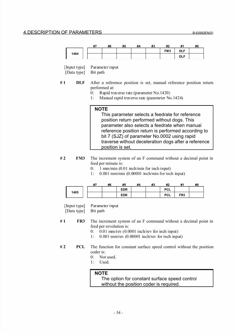
8/21/2019 30i Parameter Manual
http://slidepdf.com/reader/full/30i-parameter-manual 66/493
4.DESCRIPTION OF PARAMETERS B-63950EN/01
- 54 -
#7 #6 #5 #4 #3 #2 #1 #0
FM3 DLF1404
DLF
[Input type] Parameter input
[Data type] Bit path
# 1 DLF After a reference position is set, manual reference position return
performed at:
0: Rapid traverse rate (parameter No.1420)
1: Manual rapid traverse rate (parameter No.1424)
NOTEThis parameter selects a feedrate for referenceposition return performed without dogs. Thisparameter also selects a feedrate when manualreference position return is performed according tobit 7 (SJZ) of parameter No.0002 using rapidtraverse without deceleration dogs after a referenceposition is set.
# 2 FM3 The increment system of an F command without a decimal point in
feed per minute is:
0: 1 mm/min (0.01 inch/min for inch input)
1: 0.001 mm/min (0.00001 inch/min for inch input)
#7 #6 #5 #4 #3 #2 #1 #0
EDR PCL1405
EDR PCL FR3
[Input type] Parameter input
[Data type] Bit path
# 1 FR3 The increment system of an F command without a decimal point in
feed per revolution is:
0: 0.01 mm/rev (0.0001 inch/rev for inch input)
1: 0.001 mm/rev (0.00001 inch/rev for inch input)
# 2 PCL The function for constant surface speed control without the position
coder is:
0: Not used.
1: Used.
NOTEThe option for constant surface speed controlwithout the position coder is required.
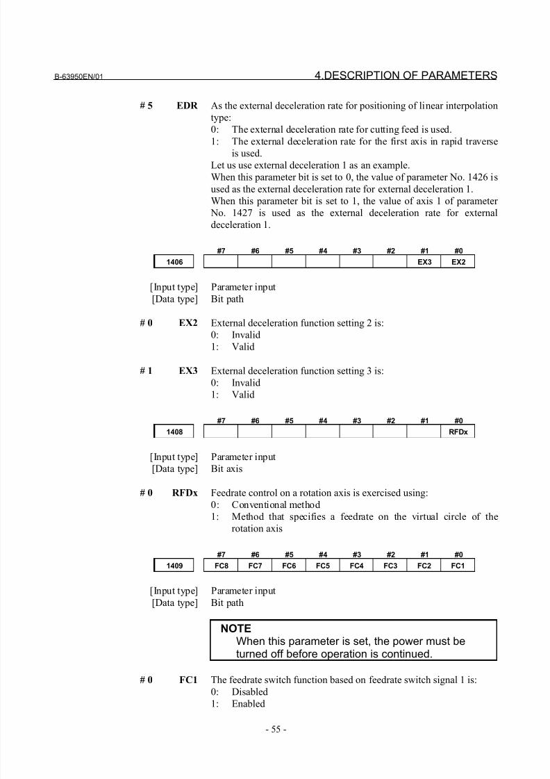
8/21/2019 30i Parameter Manual
http://slidepdf.com/reader/full/30i-parameter-manual 67/493
B-63950EN/01 4.DESCRIPTION OF PARAMETERS
- 55 -
# 5 EDR As the external deceleration rate for positioning of linear interpolation
type:
0: The external deceleration rate for cutting feed is used.
1: The external deceleration rate for the first axis in rapid traverse
is used.
Let us use external deceleration 1 as an example.
When this parameter bit is set to 0, the value of parameter No. 1426 is
used as the external deceleration rate for external deceleration 1.
When this parameter bit is set to 1, the value of axis 1 of parameter
No. 1427 is used as the external deceleration rate for external
deceleration 1.
#7 #6 #5 #4 #3 #2 #1 #0
1406 EX3 EX2
[Input type] Parameter input
[Data type] Bit path
# 0 EX2 External deceleration function setting 2 is:
0: Invalid
1: Valid
# 1 EX3 External deceleration function setting 3 is:
0: Invalid
1: Valid
#7 #6 #5 #4 #3 #2 #1 #0
1408 RFDx
[Input type] Parameter input
[Data type] Bit axis
# 0 RFDx Feedrate control on a rotation axis is exercised using:
0: Conventional method
1: Method that specifies a feedrate on the virtual circle of the
rotation axis
#7 #6 #5 #4 #3 #2 #1 #0
1409 FC8 FC7 FC6 FC5 FC4 FC3 FC2 FC1
[Input type] Parameter input
[Data type] Bit path
NOTEWhen this parameter is set, the power must beturned off before operation is continued.
# 0 FC1 The feedrate switch function based on feedrate switch signal 1 is:0: Disabled
1: Enabled
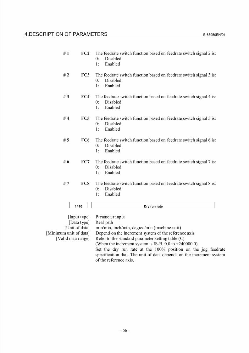
8/21/2019 30i Parameter Manual
http://slidepdf.com/reader/full/30i-parameter-manual 68/493
4.DESCRIPTION OF PARAMETERS B-63950EN/01
- 56 -
# 1 FC2 The feedrate switch function based on feedrate switch signal 2 is:
0: Disabled
1: Enabled
# 2 FC3 The feedrate switch function based on feedrate switch signal 3 is:
0: Disabled
1: Enabled
# 3 FC4 The feedrate switch function based on feedrate switch signal 4 is:
0: Disabled
1: Enabled
# 4 FC5 The feedrate switch function based on feedrate switch signal 5 is:
0: Disabled1: Enabled
# 5 FC6 The feedrate switch function based on feedrate switch signal 6 is:
0: Disabled
1: Enabled
# 6 FC7 The feedrate switch function based on feedrate switch signal 7 is:
0: Disabled
1: Enabled
# 7 FC8 The feedrate switch function based on feedrate switch signal 8 is:0: Disabled
1: Enabled
1410 Dry run rate
[Input type] Parameter input
[Data type] Real path
[Unit of data] mm/min, inch/min, degree/min (machine unit)
[Minimum unit of data] Depend on the increment system of the reference axis
[Valid data range] Refer to the standard parameter setting table (C)
(When the increment system is IS-B, 0.0 to +240000.0)
Set the dry run rate at the 100% position on the jog feedrate
specification dial. The unit of data depends on the increment system
of the reference axis.
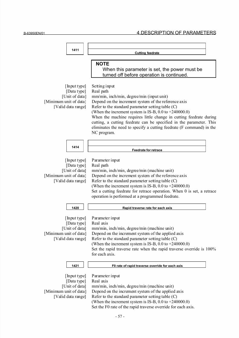
8/21/2019 30i Parameter Manual
http://slidepdf.com/reader/full/30i-parameter-manual 69/493
B-63950EN/01 4.DESCRIPTION OF PARAMETERS
- 57 -
1411Cutting feedrate
NOTEWhen this parameter is set, the power must beturned off before operation is continued.
[Input type] Setting input
[Data type] Real path
[Unit of data] mm/min, inch/min, degree/min (input unit)
[Minimum unit of data] Depend on the increment system of the reference axis
[Valid data range] Refer to the standard parameter setting table (C)
(When the increment system is IS-B, 0.0 to +240000.0)
When the machine requires little change in cutting feedrate duringcutting, a cutting feedrate can be specified in the parameter. This
eliminates the need to specify a cutting feedrate (F command) in the
NC program.
1414Feedrate for retrace
[Input type] Parameter input
[Data type] Real path
[Unit of data] mm/min, inch/min, degree/min (machine unit)
[Minimum unit of data] Depend on the increment system of the reference axis[Valid data range] Refer to the standard parameter setting table (C)
(When the increment system is IS-B, 0.0 to +240000.0)
Set a cutting feedrate for retrace operation. When 0 is set, a retrace
operation is performed at a programmed feedrate.
1420 Rapid traverse rate for each axis
[Input type] Parameter input
[Data type] Real axis
[Unit of data] mm/min, inch/min, degree/min (machine unit)
[Minimum unit of data] Depend on the increment system of the applied axis
[Valid data range] Refer to the standard parameter setting table (C)
(When the increment system is IS-B, 0.0 to +240000.0)
Set the rapid traverse rate when the rapid traverse override is 100%
for each axis.
1421 F0 rate of rapid traverse override for each axis
[Input type] Parameter input
[Data type] Real axis
[Unit of data] mm/min, inch/min, degree/min (machine unit)
[Minimum unit of data] Depend on the increment system of the applied axis
[Valid data range] Refer to the standard parameter setting table (C)(When the increment system is IS-B, 0.0 to +240000.0)
Set the F0 rate of the rapid traverse override for each axis.
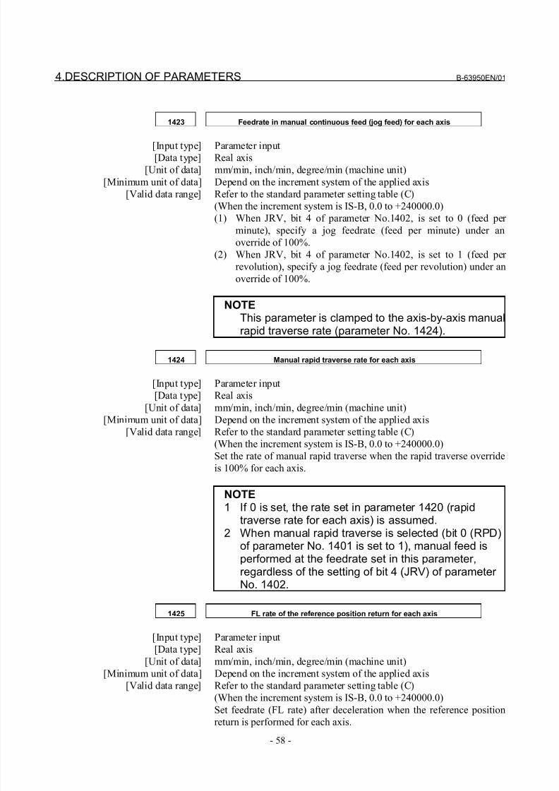
8/21/2019 30i Parameter Manual
http://slidepdf.com/reader/full/30i-parameter-manual 70/493
4.DESCRIPTION OF PARAMETERS B-63950EN/01
- 58 -
1423 Feedrate in manual continuous feed (jog feed) for each axis
[Input type] Parameter input
[Data type] Real axis
[Unit of data] mm/min, inch/min, degree/min (machine unit)
[Minimum unit of data] Depend on the increment system of the applied axis
[Valid data range] Refer to the standard parameter setting table (C)
(When the increment system is IS-B, 0.0 to +240000.0)
(1) When JRV, bit 4 of parameter No.1402, is set to 0 (feed per
minute), specify a jog feedrate (feed per minute) under an
override of 100%.
(2) When JRV, bit 4 of parameter No.1402, is set to 1 (feed per
revolution), specify a jog feedrate (feed per revolution) under an
override of 100%.
NOTEThis parameter is clamped to the axis-by-axis manualrapid traverse rate (parameter No. 1424).
1424 Manual rapid traverse rate for each axis
[Input type] Parameter input
[Data type] Real axis
[Unit of data] mm/min, inch/min, degree/min (machine unit)
[Minimum unit of data] Depend on the increment system of the applied axis
[Valid data range] Refer to the standard parameter setting table (C)
(When the increment system is IS-B, 0.0 to +240000.0)
Set the rate of manual rapid traverse when the rapid traverse override
is 100% for each axis.
NOTE1 If 0 is set, the rate set in parameter 1420 (rapid
traverse rate for each axis) is assumed.2 When manual rapid traverse is selected (bit 0 (RPD)
of parameter No. 1401 is set to 1), manual feed isperformed at the feedrate set in this parameter,regardless of the setting of bit 4 (JRV) of parameter No. 1402.
1425 FL rate of the reference position return for each axis
[Input type] Parameter input
[Data type] Real axis
[Unit of data] mm/min, inch/min, degree/min (machine unit)
[Minimum unit of data] Depend on the increment system of the applied axis
[Valid data range] Refer to the standard parameter setting table (C)
(When the increment system is IS-B, 0.0 to +240000.0)
Set feedrate (FL rate) after deceleration when the reference position
return is performed for each axis.
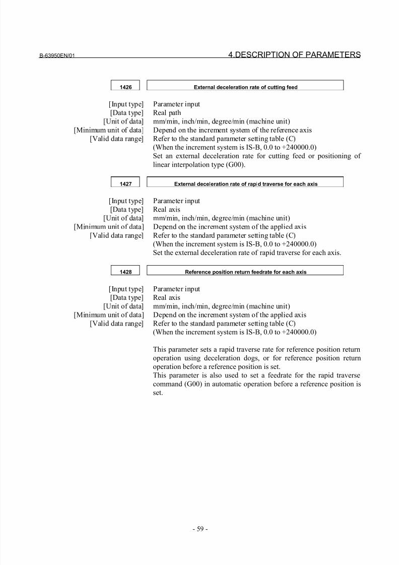
8/21/2019 30i Parameter Manual
http://slidepdf.com/reader/full/30i-parameter-manual 71/493
B-63950EN/01 4.DESCRIPTION OF PARAMETERS
- 59 -
1426 External deceleration rate of cutting feed
[Input type] Parameter input
[Data type] Real path
[Unit of data] mm/min, inch/min, degree/min (machine unit)
[Minimum unit of data] Depend on the increment system of the reference axis
[Valid data range] Refer to the standard parameter setting table (C)
(When the increment system is IS-B, 0.0 to +240000.0)
Set an external deceleration rate for cutting feed or positioning of
linear interpolation type (G00).
1427 External deceleration rate of rapid traverse for each axis
[Input type] Parameter input
[Data type] Real axis
[Unit of data] mm/min, inch/min, degree/min (machine unit)
[Minimum unit of data] Depend on the increment system of the applied axis
[Valid data range] Refer to the standard parameter setting table (C)
(When the increment system is IS-B, 0.0 to +240000.0)
Set the external deceleration rate of rapid traverse for each axis.
1428 Reference position return feedrate for each axis
[Input type] Parameter input
[Data type] Real axis[Unit of data] mm/min, inch/min, degree/min (machine unit)
[Minimum unit of data] Depend on the increment system of the applied axis
[Valid data range] Refer to the standard parameter setting table (C)
(When the increment system is IS-B, 0.0 to +240000.0)
This parameter sets a rapid traverse rate for reference position return
operation using deceleration dogs, or for reference position return
operation before a reference position is set.
This parameter is also used to set a feedrate for the rapid traverse
command (G00) in automatic operation before a reference position is
set.
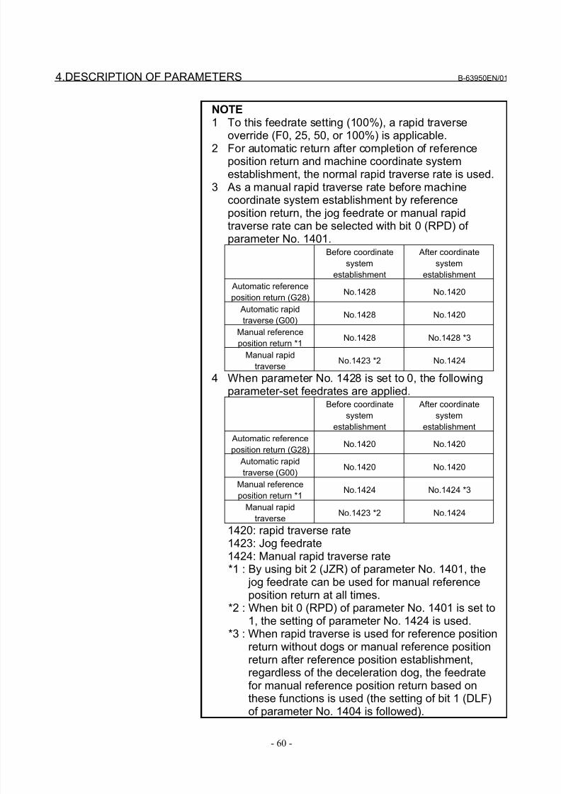
8/21/2019 30i Parameter Manual
http://slidepdf.com/reader/full/30i-parameter-manual 72/493
4.DESCRIPTION OF PARAMETERS B-63950EN/01
- 60 -
NOTE1 To this feedrate setting (100%), a rapid traverse
override (F0, 25, 50, or 100%) is applicable.2 For automatic return after completion of referenceposition return and machine coordinate systemestablishment, the normal rapid traverse rate is used.
3 As a manual rapid traverse rate before machinecoordinate system establishment by referenceposition return, the jog feedrate or manual rapidtraverse rate can be selected with bit 0 (RPD) of parameter No. 1401.
Before coordinate
system
establishment
After coordinate
system
establishment Automatic reference
position return (G28)No.1428 No.1420
Automatic rapid
traverse (G00)No.1428 No.1420
Manual reference
position return *1No.1428 No.1428 *3
Manual rapid
traverseNo.1423 *2 No.1424
4 When parameter No. 1428 is set to 0, the followingparameter-set feedrates are applied.
Before coordinate
systemestablishment
After coordinate
systemestablishment
Automatic reference
position return (G28)No.1420 No.1420
Automatic rapid
traverse (G00)No.1420 No.1420
Manual reference
position return *1No.1424 No.1424 *3
Manual rapid
traverseNo.1423 *2 No.1424
1420: rapid traverse rate1423: Jog feedrate
1424: Manual rapid traverse rate*1 : By using bit 2 (JZR) of parameter No. 1401, the
jog feedrate can be used for manual referenceposition return at all times.
*2 : When bit 0 (RPD) of parameter No. 1401 is set to1, the setting of parameter No. 1424 is used.
*3 : When rapid traverse is used for reference positionreturn without dogs or manual reference positionreturn after reference position establishment,regardless of the deceleration dog, the feedratefor manual reference position return based on
these functions is used (the setting of bit 1 (DLF)of parameter No. 1404 is followed).
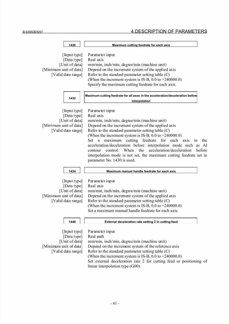
8/21/2019 30i Parameter Manual
http://slidepdf.com/reader/full/30i-parameter-manual 73/493
B-63950EN/01 4.DESCRIPTION OF PARAMETERS
- 61 -
1430 Maximum cutting feedrate for each axis
[Input type] Parameter input[Data type] Real axis
[Unit of data] mm/min, inch/min, degree/min (machine unit)
[Minimum unit of data] Depend on the increment system of the applied axis
[Valid data range] Refer to the standard parameter setting table (C)
(When the increment system is IS-B, 0.0 to +240000.0)
Specify the maximum cutting feedrate for each axis.
1432Maximum cutting feedrate for all axes in the acceleration/deceleration before
interpolation
[Input type] Parameter input
[Data type] Real axis
[Unit of data] mm/min, inch/min, degree/min (machine unit)
[Minimum unit of data] Depend on the increment system of the applied axis
[Valid data range] Refer to the standard parameter setting table (C)
(When the increment system is IS-B, 0.0 to +240000.0)
Set a maximum cutting feedrate for each axis in the
acceleration/deceleration before interpolation mode such as AI
contour control. When the acceleration/deceleration before
interpolation mode is not set, the maximum cutting feedrate set in
parameter No. 1430 is used.
1434 Maximum manual handle feedrate for each axis
[Input type] Parameter input
[Data type] Real axis
[Unit of data] mm/min, inch/min, degree/min (machine unit)
[Minimum unit of data] Depend on the increment system of the applied axis
[Valid data range] Refer to the standard parameter setting table (C)
(When the increment system is IS-B, 0.0 to +240000.0)
Set a maximum manual handle feedrate for each axis.
1440 External deceleration rate setting 2 in cutting feed
[Input type] Parameter input
[Data type] Real path
[Unit of data] mm/min, inch/min, degree/min (machine unit)
[Minimum unit of data] Depend on the increment system of the reference axis
[Valid data range] Refer to the standard parameter setting table (C)
(When the increment system is IS-B, 0.0 to +240000.0)
Set external deceleration rate 2 for cutting feed or positioning of
linear interpolation type (G00).
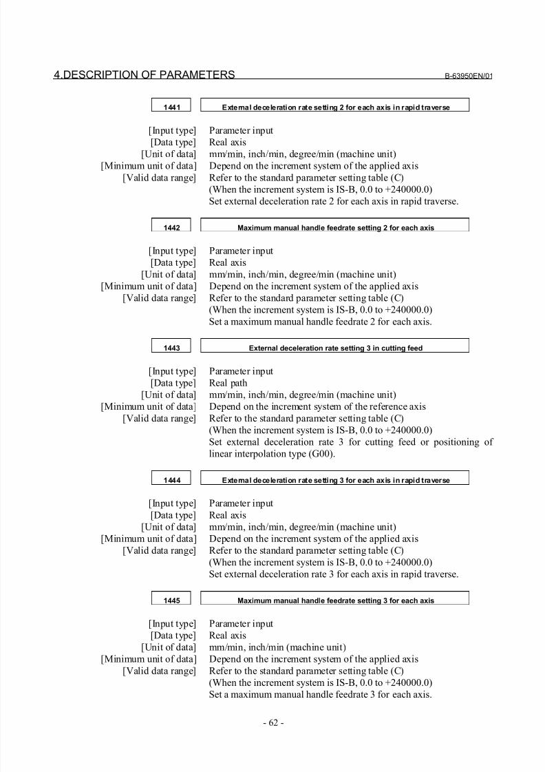
8/21/2019 30i Parameter Manual
http://slidepdf.com/reader/full/30i-parameter-manual 74/493
4.DESCRIPTION OF PARAMETERS B-63950EN/01
- 62 -
1441 External deceleration rate setting 2 for each axis in rapid traverse
[Input type] Parameter input[Data type] Real axis
[Unit of data] mm/min, inch/min, degree/min (machine unit)
[Minimum unit of data] Depend on the increment system of the applied axis
[Valid data range] Refer to the standard parameter setting table (C)
(When the increment system is IS-B, 0.0 to +240000.0)
Set external deceleration rate 2 for each axis in rapid traverse.
1442 Maximum manual handle feedrate setting 2 for each axis
[Input type] Parameter input
[Data type] Real axis
[Unit of data] mm/min, inch/min, degree/min (machine unit)
[Minimum unit of data] Depend on the increment system of the applied axis
[Valid data range] Refer to the standard parameter setting table (C)
(When the increment system is IS-B, 0.0 to +240000.0)
Set a maximum manual handle feedrate 2 for each axis.
1443 External deceleration rate setting 3 in cutting feed
[Input type] Parameter input
[Data type] Real path
[Unit of data] mm/min, inch/min, degree/min (machine unit)
[Minimum unit of data] Depend on the increment system of the reference axis[Valid data range] Refer to the standard parameter setting table (C)
(When the increment system is IS-B, 0.0 to +240000.0)
Set external deceleration rate 3 for cutting feed or positioning of
linear interpolation type (G00).
1444 External deceleration rate setting 3 for each axis in rapid traverse
[Input type] Parameter input
[Data type] Real axis
[Unit of data] mm/min, inch/min, degree/min (machine unit)
[Minimum unit of data] Depend on the increment system of the applied axis[Valid data range] Refer to the standard parameter setting table (C)
(When the increment system is IS-B, 0.0 to +240000.0)
Set external deceleration rate 3 for each axis in rapid traverse.
1445 Maximum manual handle feedrate setting 3 for each axis
[Input type] Parameter input
[Data type] Real axis
[Unit of data] mm/min, inch/min (machine unit)
[Minimum unit of data] Depend on the increment system of the applied axis
[Valid data range] Refer to the standard parameter setting table (C)
(When the increment system is IS-B, 0.0 to +240000.0)
Set a maximum manual handle feedrate 3 for each axis.
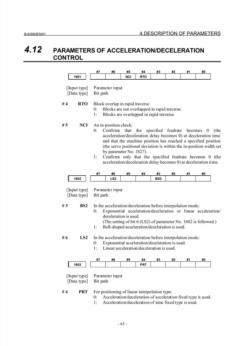
8/21/2019 30i Parameter Manual
http://slidepdf.com/reader/full/30i-parameter-manual 75/493
B-63950EN/01 4.DESCRIPTION OF PARAMETERS
- 63 -
4.12 PARAMETERS OF ACCELERATION/DECELERATION
CONTROL
#7 #6 #5 #4 #3 #2 #1 #0
1601 NCI RTO
[Input type] Parameter input
[Data type] Bit path
# 4 RTO Block overlap in rapid traverse
0: Blocks are not overlapped in rapid traverse.
1: Blocks are overlapped in rapid traverse.
# 5 NCI An in-position check:
0: Confirms that the specified feedrate becomes 0 (the
acceleration/deceleration delay becomes 0) at deceleration time
and that the machine position has reached a specified position
(the servo positional deviation is within the in-position width set
by parameter No. 1827).
1: Confirms only that the specified feedrate becomes 0 (the
acceleration/deceleration delay becomes 0) at deceleration time.
#7 #6 #5 #4 #3 #2 #1 #0
1602 LS2 BS2
[Input type] Parameter input
[Data type] Bit path
# 3 BS2 In the acceleration/deceleration before interpolation mode:
0: Exponential acceleration/deceleration or linear acceleration/
deceleration is used.
(The setting of bit 6 (LS2) of parameter No. 1602 is followed.)
1: Bell-shaped acceleration/deceleration is used.
# 6 LS2 In the acceleration/deceleration before interpolation mode:
0: Exponential acceleration/deceleration is used.1: Linear acceleration/deceleration is used.
#7 #6 #5 #4 #3 #2 #1 #0
1603 PRT
[Input type] Parameter input
[Data type] Bit path
# 4 PRT For positioning of linear interpolation type:
0: Acceleration/deceleration of acceleration fixed type is used.
1: Acceleration/deceleration of time fixed type is used.
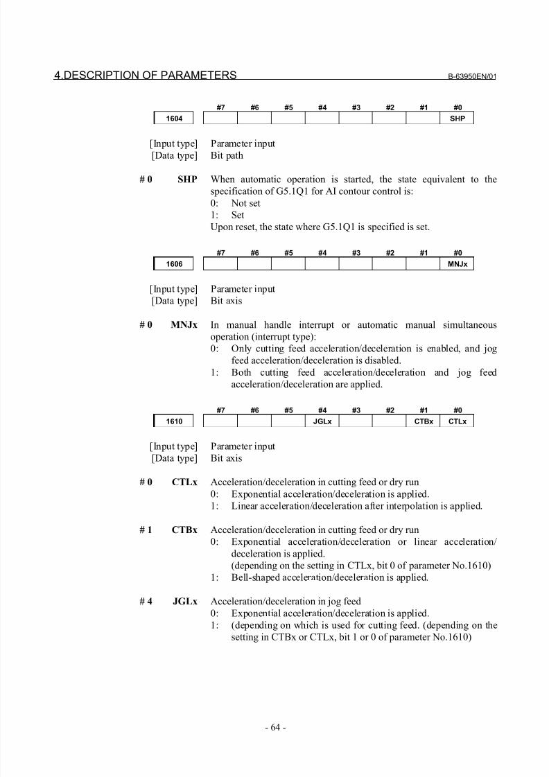
8/21/2019 30i Parameter Manual
http://slidepdf.com/reader/full/30i-parameter-manual 76/493
4.DESCRIPTION OF PARAMETERS B-63950EN/01
- 64 -
#7 #6 #5 #4 #3 #2 #1 #0
1604 SHP
[Input type] Parameter input
[Data type] Bit path
# 0 SHP When automatic operation is started, the state equivalent to the
specification of G5.1Q1 for AI contour control is:
0: Not set
1: Set
Upon reset, the state where G5.1Q1 is specified is set.
#7 #6 #5 #4 #3 #2 #1 #0
1606 MNJx
[Input type] Parameter input
[Data type] Bit axis
# 0 MNJx In manual handle interrupt or automatic manual simultaneous
operation (interrupt type):
0: Only cutting feed acceleration/deceleration is enabled, and jog
feed acceleration/deceleration is disabled.
1: Both cutting feed acceleration/deceleration and jog feed
acceleration/deceleration are applied.
#7 #6 #5 #4 #3 #2 #1 #0
1610 JGLx CTBx CTLx
[Input type] Parameter input
[Data type] Bit axis
# 0 CTLx Acceleration/deceleration in cutting feed or dry run
0: Exponential acceleration/deceleration is applied.
1: Linear acceleration/deceleration after interpolation is applied.
# 1 CTBx Acceleration/deceleration in cutting feed or dry run
0: Exponential acceleration/deceleration or linear acceleration/deceleration is applied.
(depending on the setting in CTLx, bit 0 of parameter No.1610)
1: Bell-shaped acceleration/deceleration is applied.
# 4 JGLx Acceleration/deceleration in jog feed
0: Exponential acceleration/deceleration is applied.
1: (depending on which is used for cutting feed. (depending on the
setting in CTBx or CTLx, bit 1 or 0 of parameter No.1610)
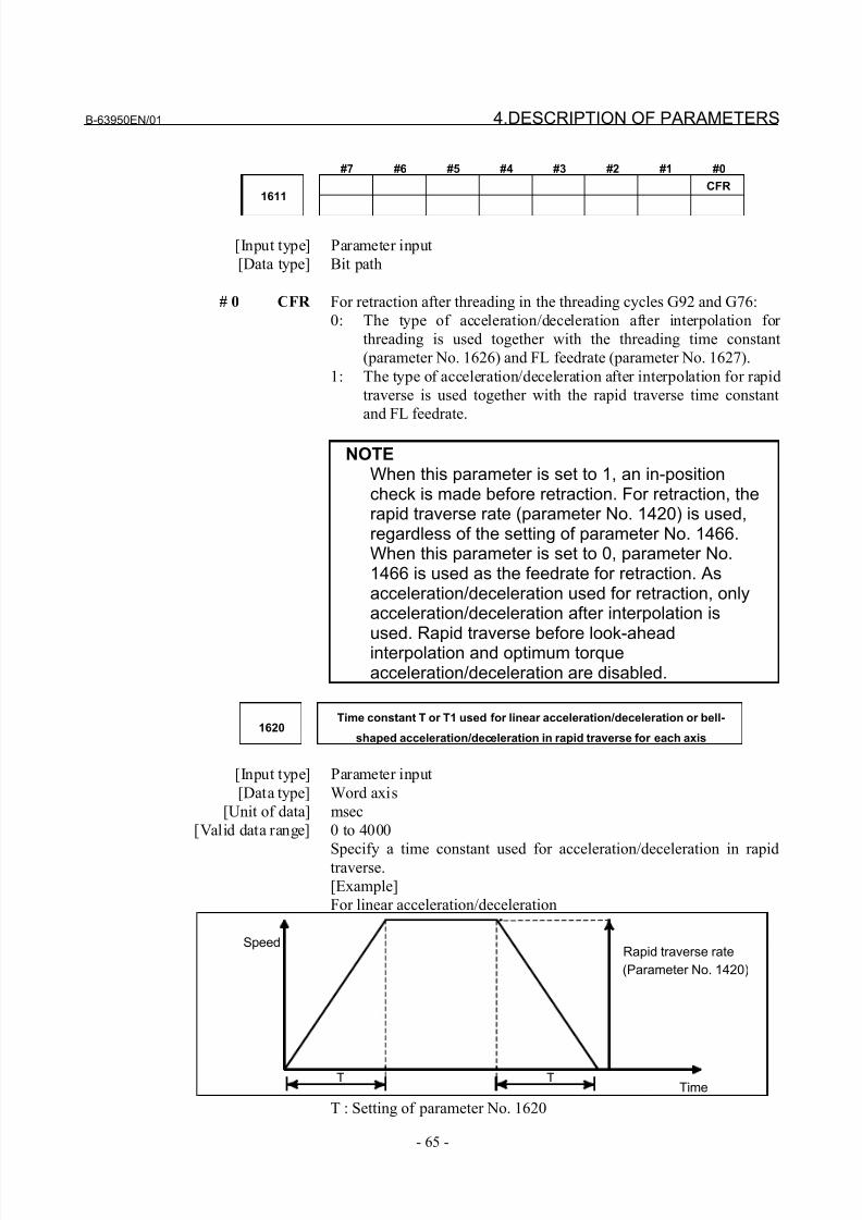
8/21/2019 30i Parameter Manual
http://slidepdf.com/reader/full/30i-parameter-manual 77/493
B-63950EN/01 4.DESCRIPTION OF PARAMETERS
- 65 -
#7 #6 #5 #4 #3 #2 #1 #0
CFR1611
[Input type] Parameter input
[Data type] Bit path
# 0 CFR For retraction after threading in the threading cycles G92 and G76:
0: The type of acceleration/deceleration after interpolation for
threading is used together with the threading time constant
(parameter No. 1626) and FL feedrate (parameter No. 1627).
1: The type of acceleration/deceleration after interpolation for rapid
traverse is used together with the rapid traverse time constant
and FL feedrate.
NOTEWhen this parameter is set to 1, an in-positioncheck is made before retraction. For retraction, therapid traverse rate (parameter No. 1420) is used,regardless of the setting of parameter No. 1466.When this parameter is set to 0, parameter No.1466 is used as the feedrate for retraction. Asacceleration/deceleration used for retraction, onlyacceleration/deceleration after interpolation is
used. Rapid traverse before look-aheadinterpolation and optimum torqueacceleration/deceleration are disabled.
1620Time constant T or T1 used for linear acceleration/deceleration or bell-
shaped acceleration/deceleration in rapid traverse for each axis
[Input type] Parameter input
[Data type] Word axis
[Unit of data] msec
[Valid data range] 0 to 4000
Specify a time constant used for acceleration/deceleration in rapidtraverse.
[Example]
For linear acceleration/deceleration
SpeedRapid traverse rate
(Parameter No. 1420)
TimeTT
T : Setting of parameter No. 1620
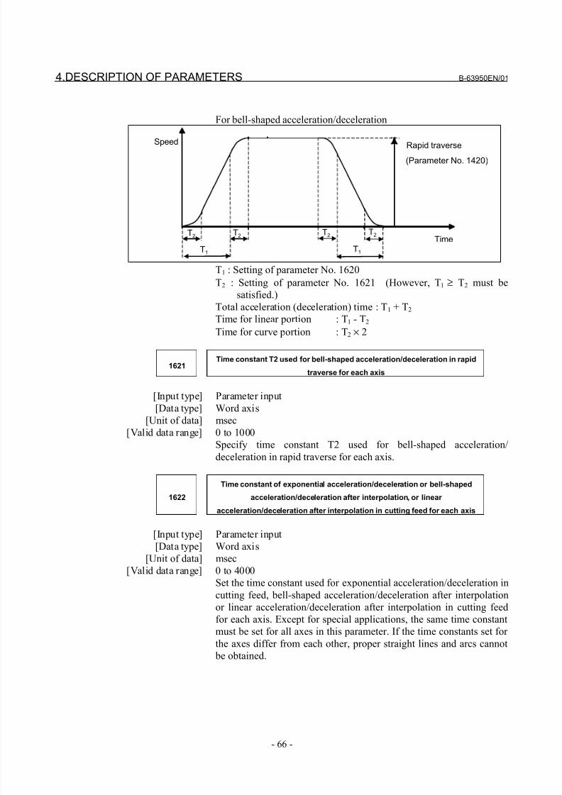
8/21/2019 30i Parameter Manual
http://slidepdf.com/reader/full/30i-parameter-manual 78/493
4.DESCRIPTION OF PARAMETERS B-63950EN/01
- 66 -
For bell-shaped acceleration/deceleration
Speed Rapid traverse
(Parameter No. 1420)
Time
T1
T2 T2T2 T2
T1
T1 : Setting of parameter No. 1620
T2 : Setting of parameter No. 1621 (However, T1 ≥ T2 must be
satisfied.)
Total acceleration (deceleration) time : T1 + T2
Time for linear portion : T1 - T2
Time for curve portion : T2 × 2
1621Time constant T2 used for bell-shaped acceleration/deceleration in rapid
traverse for each axis
[Input type] Parameter input
[Data type] Word axis
[Unit of data] msec[Valid data range] 0 to 1000
Specify time constant T2 used for bell-shaped acceleration/
deceleration in rapid traverse for each axis.
1622
Time constant of exponential acceleration/deceleration or bell-shaped
acceleration/deceleration after interpolation, or linear
acceleration/deceleration after interpolation in cutting feed for each axis
[Input type] Parameter input
[Data type] Word axis
[Unit of data] msec[Valid data range] 0 to 4000
Set the time constant used for exponential acceleration/deceleration in
cutting feed, bell-shaped acceleration/deceleration after interpolation
or linear acceleration/deceleration after interpolation in cutting feed
for each axis. Except for special applications, the same time constant
must be set for all axes in this parameter. If the time constants set for
the axes differ from each other, proper straight lines and arcs cannot
be obtained.
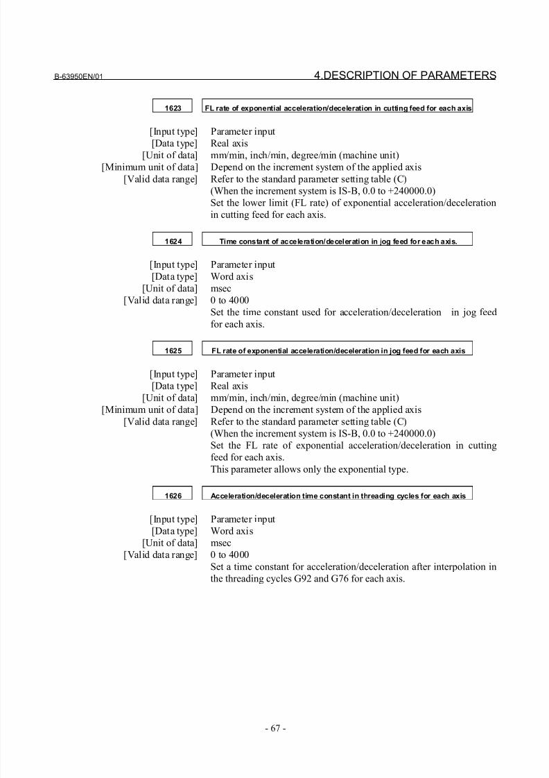
8/21/2019 30i Parameter Manual
http://slidepdf.com/reader/full/30i-parameter-manual 79/493
B-63950EN/01 4.DESCRIPTION OF PARAMETERS
- 67 -
1623 FL rate of exponential acceleration/deceleration in cutting feed for each axis
[Input type] Parameter input[Data type] Real axis
[Unit of data] mm/min, inch/min, degree/min (machine unit)
[Minimum unit of data] Depend on the increment system of the applied axis
[Valid data range] Refer to the standard parameter setting table (C)
(When the increment system is IS-B, 0.0 to +240000.0)
Set the lower limit (FL rate) of exponential acceleration/deceleration
in cutting feed for each axis.
1624 Time constant of acceleration/deceleration in jog feed for each axis.
[Input type] Parameter input
[Data type] Word axis
[Unit of data] msec
[Valid data range] 0 to 4000
Set the time constant used for acceleration/deceleration in jog feed
for each axis.
1625 FL rate of exponential acceleration/deceleration in jog feed for each axis
[Input type] Parameter input
[Data type] Real axis
[Unit of data] mm/min, inch/min, degree/min (machine unit)
[Minimum unit of data] Depend on the increment system of the applied axis[Valid data range] Refer to the standard parameter setting table (C)
(When the increment system is IS-B, 0.0 to +240000.0)
Set the FL rate of exponential acceleration/deceleration in cutting
feed for each axis.
This parameter allows only the exponential type.
1626 Acceleration/deceleration time constant in threading cycles for each axis
[Input type] Parameter input
[Data type] Word axis
[Unit of data] msec[Valid data range] 0 to 4000
Set a time constant for acceleration/deceleration after interpolation in
the threading cycles G92 and G76 for each axis.
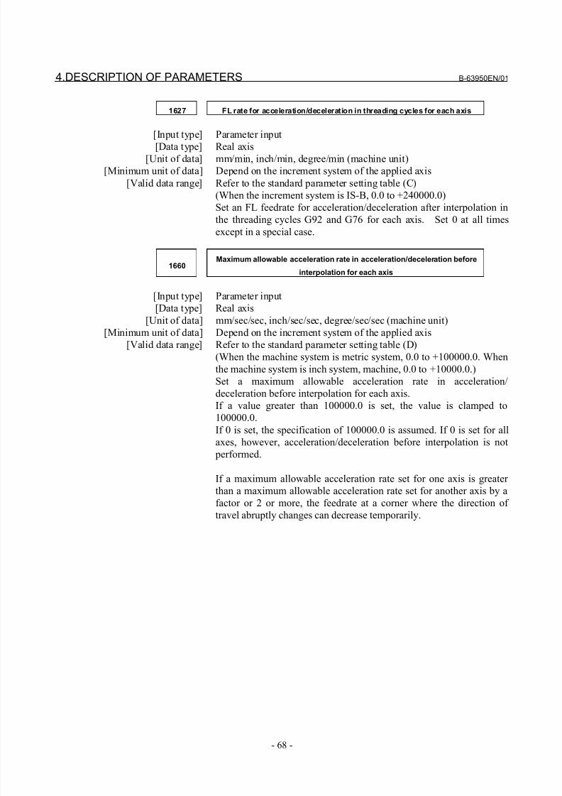
8/21/2019 30i Parameter Manual
http://slidepdf.com/reader/full/30i-parameter-manual 80/493
4.DESCRIPTION OF PARAMETERS B-63950EN/01
- 68 -
1627 FL rate for acceleration/deceleration in threading cycles for each axis
[Input type] Parameter input[Data type] Real axis
[Unit of data] mm/min, inch/min, degree/min (machine unit)
[Minimum unit of data] Depend on the increment system of the applied axis
[Valid data range] Refer to the standard parameter setting table (C)
(When the increment system is IS-B, 0.0 to +240000.0)
Set an FL feedrate for acceleration/deceleration after interpolation in
the threading cycles G92 and G76 for each axis. Set 0 at all times
except in a special case.
1660Maximum allowable acceleration rate in acceleration/deceleration before
interpolation for each axis
[Input type] Parameter input
[Data type] Real axis
[Unit of data] mm/sec/sec, inch/sec/sec, degree/sec/sec (machine unit)
[Minimum unit of data] Depend on the increment system of the applied axis
[Valid data range] Refer to the standard parameter setting table (D)
(When the machine system is metric system, 0.0 to +100000.0. When
the machine system is inch system, machine, 0.0 to +10000.0.)
Set a maximum allowable acceleration rate in acceleration/
deceleration before interpolation for each axis.
If a value greater than 100000.0 is set, the value is clamped to
100000.0.If 0 is set, the specification of 100000.0 is assumed. If 0 is set for all
axes, however, acceleration/deceleration before interpolation is not
performed.
If a maximum allowable acceleration rate set for one axis is greater
than a maximum allowable acceleration rate set for another axis by a
factor or 2 or more, the feedrate at a corner where the direction of
travel abruptly changes can decrease temporarily.
8/21/2019 30i Parameter Manual
http://slidepdf.com/reader/full/30i-parameter-manual 81/493
B-63950EN/01 4.DESCRIPTION OF PARAMETERS
- 69 -
1671
Maximum allowable acceleration rate in acceleration/deceleration before
interpolation for linear rapid traverse for each axis, or maximum allowable
reference acceleration rate in optimum torque acceleration/deceleration
[Input type] Parameter input
[Data type] Real axis
[Unit of data] mm/sec/sec, inch/sec/sec, degree/sec/sec (machine unit)
[Minimum unit of data] Depend on the increment system of the applied axis
[Valid data range] Refer to the standard parameter setting table (D)
(When the machine system is metric system, 0.0 to +100000.0. When
the machine system is inch system, machine, 0.0 to +10000.0.)
(1) Set a maximum allowable acceleration rate in acceleration/
deceleration before interpolation for linear rapid traverse.
If a value greater than 100000.0, the value is clamped to
100000.0.If 0 is set, the specification of the following is assumed:
1000.0 mm/sec/sec
100.0 inch/sec/sec
100.0 degrees/sec/sec
If 0 is specified for all axes, however, acceleration/deceleration
before interpolation is not performed.
(2) Maximum allowable reference acceleration rate in optimum
torque acceleration/deceleration
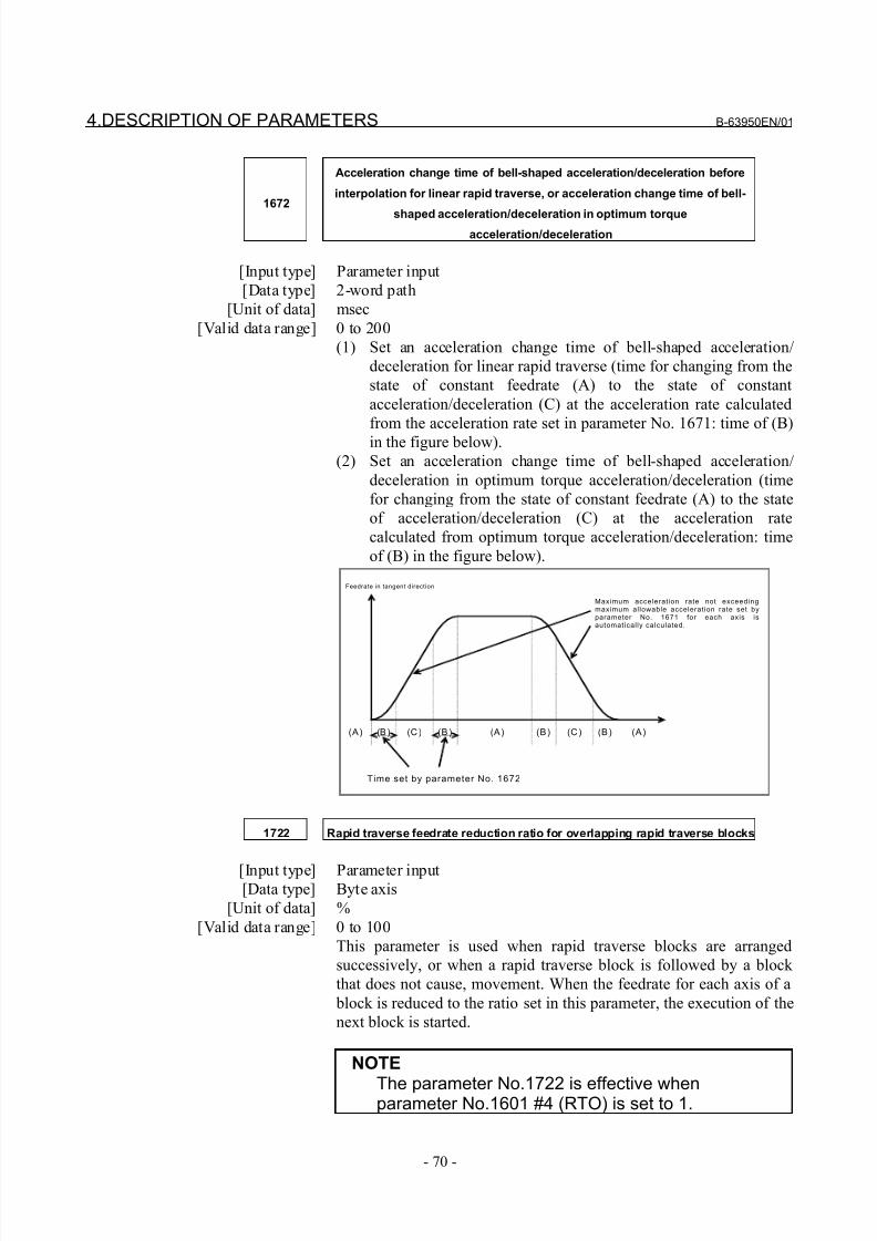
8/21/2019 30i Parameter Manual
http://slidepdf.com/reader/full/30i-parameter-manual 82/493
4.DESCRIPTION OF PARAMETERS B-63950EN/01
- 70 -
1672
Acceleration change time of bell-shaped acceleration/deceleration before
interpolation for linear rapid traverse, or acceleration change time of bell-
shaped acceleration/deceleration in optimum torqueacceleration/deceleration
[Input type] Parameter input
[Data type] 2-word path
[Unit of data] msec
[Valid data range] 0 to 200
(1) Set an acceleration change time of bell-shaped acceleration/
deceleration for linear rapid traverse (time for changing from the
state of constant feedrate (A) to the state of constant
acceleration/deceleration (C) at the acceleration rate calculated
from the acceleration rate set in parameter No. 1671: time of (B)
in the figure below).
(2) Set an acceleration change time of bell-shaped acceleration/
deceleration in optimum torque acceleration/deceleration (time
for changing from the state of constant feedrate (A) to the state
of acceleration/deceleration (C) at the acceleration rate
calculated from optimum torque acceleration/deceleration: time
of (B) in the figure below).
Feedrate in tangent direction
Maximum acceleration rate not exceedingmaximum allowable acceleration rate set byparameter No. 1671 for each axis isautomatically calculated.
Time set by parameter No. 1672
(A) (B) (B) (B) (B)(A) (A)(C ) (C )
1722 Rapid traverse feedrate reduction ratio for overlapping rapid traverse blocks
[Input type] Parameter input[Data type] Byte axis
[Unit of data] %
[Valid data range] 0 to 100
This parameter is used when rapid traverse blocks are arranged
successively, or when a rapid traverse block is followed by a block
that does not cause, movement. When the feedrate for each axis of a
block is reduced to the ratio set in this parameter, the execution of the
next block is started.
NOTE
The parameter No.1722 is effective whenparameter No.1601 #4 (RTO) is set to 1.
8/21/2019 30i Parameter Manual
http://slidepdf.com/reader/full/30i-parameter-manual 83/493
B-63950EN/01 4.DESCRIPTION OF PARAMETERS
- 71 -
1732Minimum allowable feedrate for the deceleration function based on
acceleration in circular interpolation
[Input type] Parameter input
[Data type] Real path
[Unit of data] mm/min, inch/min, degree/min (machine unit)
[Minimum unit of data] Depend on the increment system of the reference axis
[Valid data range] Refer to the standard parameter setting table (C)
(When the increment system is IS-B, 0.0 to +240000.0)
With the deceleration function based on acceleration in circular
interpolation, an optimum feedrate is automatically calculated so that
acceleration produced by changing the move direction in circular
interpolation does not exceed the maximum allowable acceleration
rate specified in parameter No. 1735.
If the radius of an arc is very small, a calculated feedrate may becometoo low.
In such a case, the feedrate is prevented from decreasing below the
value specified in this parameter.
NOTEDuring involute interpolation, the minimumallowable feedrate of "clamping of accelerationnear a basic circle" in involute interpolationautomatic feedrate control is used.
1735Maximum allowable acceleration rate for the deceleration function based on
acceleration in circular interpolation for each axis
[Input type] Parameter input
[Data type] Real axis
[Unit of data] mm/sec/sec, inch/sec/sec, degree/sec/sec (machine unit)
[Minimum unit of data] Depend on the increment system of the applied axis
[Valid data range] Refer to the standard parameter setting table (D)
(When the machine system is metric system, 0.0 to +100000.0. When
the machine system is inch system, machine, 0.0 to +10000.0.)
Set a maximum allowable acceleration rate for the deceleration
function based on acceleration in circular interpolation.Feedrate is controlled so that acceleration produced by changing the
move direction in circular interpolation does not exceed the value
specified in this parameter.
For an axis with 0 set in this parameter, the deceleration function
based on acceleration is disabled.
If a different value is set in this parameter for each axis, a feedrate is
determined from the smaller of the acceleration rates specified for the
two circular axes.
8/21/2019 30i Parameter Manual
http://slidepdf.com/reader/full/30i-parameter-manual 84/493
4.DESCRIPTION OF PARAMETERS B-63950EN/01
- 72 -
NOTEDuring involute interpolation, the minimum
allowable feedrate of "clamping of accelerationnear a basic circle" in involute interpolationautomatic feedrate control is used.
1737Maximum allowable acceleration rate for the deceleration function based on
acceleration in AI contour control for each axis
[Input type] Parameter input
[Data type] Real axis
[Unit of data] mm/sec/sec, inch/sec/sec, degree/sec/sec (machine unit)
[Minimum unit of data] Depend on the increment system of the applied axis
[Valid data range] Refer to the standard parameter setting table (D)(When the machine system is metric system, 0.0 to +100000.0. When
the machine system is inch system, machine, 0.0 to +10000.0.)
Set a maximum allowable acceleration rate produced by changing the
tool move direction.
For an axis with 0 set in this parameter, the deceleration function
based on acceleration is disabled. If 0 is set for all axes, the
deceleration function based on acceleration is not performed.
In circular interpolation, however, the deceleration function based on
feedrate control using acceleration in circular interpolation (parameter
No. 1735) is enabled.
1738Minimum allowable feedrate for the deceleration function based on
acceleration in AI contour control
[Input type] Parameter input
[Data type] Real path
[Unit of data] mm/min, inch/min, degree/min (machine unit)
[Minimum unit of data] Depend on the increment system of the reference axis
[Valid data range] Refer to the standard parameter setting table (C)
(When the increment system is IS-B, 0.0 to +240000.0)
With the deceleration function based on acceleration in AI contour
control, a feedrate most suitable for a desired figure is automatically
calculated.Depending on the figure, however, the calculated feedrate may
become too low.
In such a case, the feedrate is prevented from decreasing below the
value specified in this parameter.
If overriding using the deceleration function based on cutting load is
enabled, a feedrate lower than the minimum allowable feedrate may
be used.
8/21/2019 30i Parameter Manual
http://slidepdf.com/reader/full/30i-parameter-manual 85/493
B-63950EN/01 4.DESCRIPTION OF PARAMETERS
- 73 -
1763FL rate for acceleration/deceleration after cutting feed interpolation for each
axis in the acceleration/deceleration before interpolation mode
[Input type] Parameter input
[Data type] Real axis
[Unit of data] mm/min, inch/min, degree/min (machine unit)
[Minimum unit of data] Depend on the increment system of the applied axis
[Valid data range] Refer to the standard parameter setting table (C)
(When the increment system is IS-B, 0.0 to +240000.0)
Set a minimum allowable feedrate (FL feedrate) for acceleration/
deceleration after cutting feed interpolation in acceleration/
deceleration before interpolation as in AI contour control.
1769
Time constant for acceleration/deceleration after cutting feed interpolation in
the acceleration/deceleration before interpolation mode
[Input type] Parameter input
[Data type] Word axis
[Unit of data] msec
[Valid data range] 0 to 4000
In the acceleration/deceleration before interpolation mode as in AI
contour control, not the ordinary time constant (parameter No. 1622)
but the value of this parameter is used.
Be sure to specify the same time constant value for all axes except for
a special application. If different values are set, correct linear and
circular figures cannot be obtained.
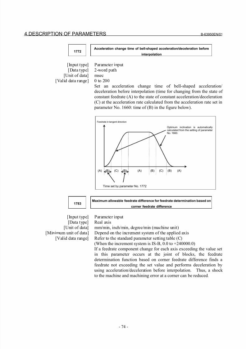
8/21/2019 30i Parameter Manual
http://slidepdf.com/reader/full/30i-parameter-manual 86/493
4.DESCRIPTION OF PARAMETERS B-63950EN/01
- 74 -
1772Acceleration change time of bell-shaped acceleration/deceleration before
interpolation
[Input type] Parameter input
[Data type] 2-word path
[Unit of data] msec
[Valid data range] 0 to 200
Set an acceleration change time of bell-shaped acceleration/
deceleration before interpolation (time for changing from the state of
constant feedrate (A) to the state of constant acceleration/deceleration
(C) at the acceleration rate calculated from the acceleration rate set in
parameter No. 1660: time of (B) in the figure below).
Feedrate in tangent direction
Optimum inclination is automaticallycalculated from the setting of parameter No. 1660.
Time set by parameter No. 1772
(A) (B) (B) (B) (B)(A) (A)(C) (C)
1783Maximum allowable feedrate difference for feedrate determination based on
corner feedrate difference
[Input type] Parameter input
[Data type] Real axis
[Unit of data] mm/min, inch/min, degree/min (machine unit)
[Minimum unit of data] Depend on the increment system of the applied axis
[Valid data range] Refer to the standard parameter setting table (C)
(When the increment system is IS-B, 0.0 to +240000.0)If a feedrate component change for each axis exceeding the value set
in this parameter occurs at the joint of blocks, the feedrate
determination function based on corner feedrate difference finds a
feedrate not exceeding the set value and performs deceleration by
using acceleration/deceleration before interpolation. Thus, a shock
to the machine and machining error at a corner can be reduced.
8/21/2019 30i Parameter Manual
http://slidepdf.com/reader/full/30i-parameter-manual 87/493
B-63950EN/01 4.DESCRIPTION OF PARAMETERS
- 75 -
1788Maximum allowable acceleration change rate in feedrate determination
based on acceleration change for each axis
[Input type] Parameter input
[Data type] Real axis
[Unit of data] mm/sec/sec, inch/sec/sec, degree/sec/sec (machine unit)
[Minimum unit of data] Depend on the increment system of the applied axis
[Valid data range] Refer to the standard parameter setting table (D)
(When the machine system is metric system, 0.0 to +100000.0. When
the machine system is inch system, machine, 0.0 to +10000.0.)
Set a maximum allowable acceleration change rate for each axis in
feedrate control based on acceleration change under control on the
rate of change of acceleration.
For an axis with 0 set in this parameter, feedrate control based on
acceleration change is disabled.If 0 is set for all axes, feedrate control based on acceleration change is
not exercised.
1789Maximum allowable acceleration change rate in feedrate determination
based on acceleration change for each axis (linear interpolation)
[Input type] Parameter input
[Data type] Real axis
[Unit of data] mm/sec/sec, inch/sec/sec, degree/sec/sec (machine unit)
[Minimum unit of data] Depend on the increment system of the applied axis
[Valid data range] Refer to the standard parameter setting table (D)(When the machine system is metric system, 0.0 to +100000.0. When
the machine system is inch system, machine, 0.0 to +10000.0.)
Set a maximum allowable acceleration change rate for each axis in
feedrate control based on acceleration change under control on the
rate of change of acceleration in successive linear interpolation
operations.
In feedrate control based on acceleration change at a corner between
linear interpolation operations, the maximum allowable acceleration
change rate not set in parameter No. 1788 but set in this parameter is
valid.
For an axis with 0 set in this parameter, the maximum allowableacceleration change rate set in parameter No. 1788 is valid.
Feedrate control based on acceleration change is disabled for an axis
with 0 set in parameter No. 1788, so that the setting of this parameter
for such an axis is ignored.
8/21/2019 30i Parameter Manual
http://slidepdf.com/reader/full/30i-parameter-manual 88/493
4.DESCRIPTION OF PARAMETERS B-63950EN/01
- 76 -
1790Ratio of change time of the rate of change of acceleration in smooth bell-
shaped acceleration/deceleration before interpolation
[Input type] Parameter input
[Data type] Byte path
[Unit of data] %
[Valid data range] 0 to 50
Set the ratio of the change time of the rate of change of acceleration to
the change time of acceleration(*1) by percentage (%) in smooth bell-
shaped acceleration/deceleration before look-ahead interpolation.
If 0 is set in this parameter or a value not within the valid data range
is specified in this parameter, smooth bell-shaped acceleration/
deceleration before look-ahead interpolation is not performed.
(*1)Parameter No. 1772 for acceleration/deceleration before look-ahead
interpolation (cutting feed).
Parameter No. 1672 for acceleration/deceleration before interpolation
in linear rapid traverse, or for optimum torque acceleration/
deceleration.
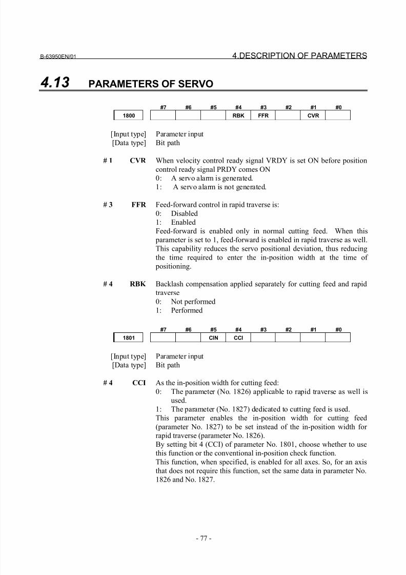
8/21/2019 30i Parameter Manual
http://slidepdf.com/reader/full/30i-parameter-manual 89/493
B-63950EN/01 4.DESCRIPTION OF PARAMETERS
- 77 -
4.13 PARAMETERS OF SERVO
#7 #6 #5 #4 #3 #2 #1 #0
1800 RBK FFR CVR
[Input type] Parameter input
[Data type] Bit path
# 1 CVR When velocity control ready signal VRDY is set ON before position
control ready signal PRDY comes ON
0: A servo alarm is generated.
1: A servo alarm is not generated.
# 3 FFR Feed-forward control in rapid traverse is:
0: Disabled
1: Enabled
Feed-forward is enabled only in normal cutting feed. When this
parameter is set to 1, feed-forward is enabled in rapid traverse as well.
This capability reduces the servo positional deviation, thus reducing
the time required to enter the in-position width at the time of
positioning.
# 4 RBK Backlash compensation applied separately for cutting feed and rapid
traverse
0: Not performed1: Performed
#7 #6 #5 #4 #3 #2 #1 #0
1801 CIN CCI
[Input type] Parameter input
[Data type] Bit path
# 4 CCI As the in-position width for cutting feed:
0: The parameter (No. 1826) applicable to rapid traverse as well is
used.1: The parameter (No. 1827) dedicated to cutting feed is used.
This parameter enables the in-position width for cutting feed
(parameter No. 1827) to be set instead of the in-position width for
rapid traverse (parameter No. 1826).
By setting bit 4 (CCI) of parameter No. 1801, choose whether to use
this function or the conventional in-position check function.
This function, when specified, is enabled for all axes. So, for an axis
that does not require this function, set the same data in parameter No.
1826 and No. 1827.
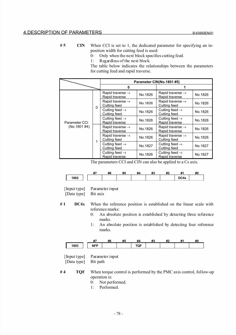
8/21/2019 30i Parameter Manual
http://slidepdf.com/reader/full/30i-parameter-manual 90/493
4.DESCRIPTION OF PARAMETERS B-63950EN/01
- 78 -
# 5 CIN When CCI is set to 1, the dedicated parameter for specifying an in-
position width for cutting feed is used:
0: Only when the next block specifies cutting feed.
1: Regardless of the next block.
The table below indicates the relationships between the parameters
for cutting feed and rapid traverse.
Parameter CIN(No.1801 #5)
0 1
Rapid traverse →Rapid traverse
No.1826Rapid traverse →Rapid traverse
No.1826
Rapid traverse →Cutting feed
No.1826Rapid traverse →Cutting feed
No.1826
Cutting feed →Cutting feed
No.1826Cutting feed →Cutting feed
No.18260
Cutting feed →Rapid traverse
No.1826 Cutting feed →Rapid traverse
No.1826
Rapid traverse →Rapid traverse
No.1826Rapid traverse →Rapid traverse
No.1826
Rapid traverse →Cutting feed
No.1826Rapid traverse →Cutting feed
No.1826
Cutting feed →Cutting feed
No.1827Cutting feed →Cutting feed
No.1827
Parameter CCI (No.1801 #4)
1
Cutting feed →Rapid traverse
No.1826Cutting feed →Rapid traverse
No.1827
The parameters CCI and CIN can also be applied to a Cs axis.
#7 #6 #5 #4 #3 #2 #1 #0
1802 DC4x
[Input type] Parameter input
[Data type] Bit axis
# 1 DC4x When the reference position is established on the linear scale with
reference marks:
0: An absolute position is established by detecting three reference
marks.
1: An absolute position is established by detecting four reference
marks.
#7 #6 #5 #4 #3 #2 #1 #0
1803 NFP TQF
[Input type] Parameter input
[Data type] Bit path
# 4 TQF When torque control is performed by the PMC axis control, follow-up
operation is:
0: Not performed.
1: Performed.
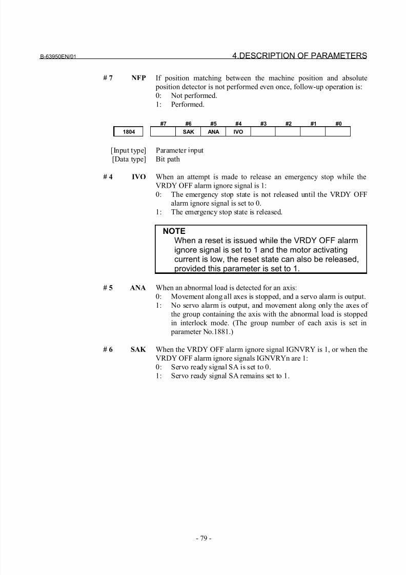
8/21/2019 30i Parameter Manual
http://slidepdf.com/reader/full/30i-parameter-manual 91/493
B-63950EN/01 4.DESCRIPTION OF PARAMETERS
- 79 -
# 7 NFP If position matching between the machine position and absolute
position detector is not performed even once, follow-up operation is:
0: Not performed.
1: Performed.
#7 #6 #5 #4 #3 #2 #1 #0
1804 SAK ANA IVO
[Input type] Parameter input
[Data type] Bit path
# 4 IVO When an attempt is made to release an emergency stop while the
VRDY OFF alarm ignore signal is 1:
0: The emergency stop state is not released until the VRDY OFF
alarm ignore signal is set to 0.1: The emergency stop state is released.
NOTEWhen a reset is issued while the VRDY OFF alarmignore signal is set to 1 and the motor activatingcurrent is low, the reset state can also be released,provided this parameter is set to 1.
# 5 ANA When an abnormal load is detected for an axis:
0: Movement along all axes is stopped, and a servo alarm is output.
1: No servo alarm is output, and movement along only the axes of
the group containing the axis with the abnormal load is stopped
in interlock mode. (The group number of each axis is set in
parameter No.1881.)
# 6 SAK When the VRDY OFF alarm ignore signal IGNVRY is 1, or when the
VRDY OFF alarm ignore signals IGNVRYn are 1:
0: Servo ready signal SA is set to 0.
1: Servo ready signal SA remains set to 1.
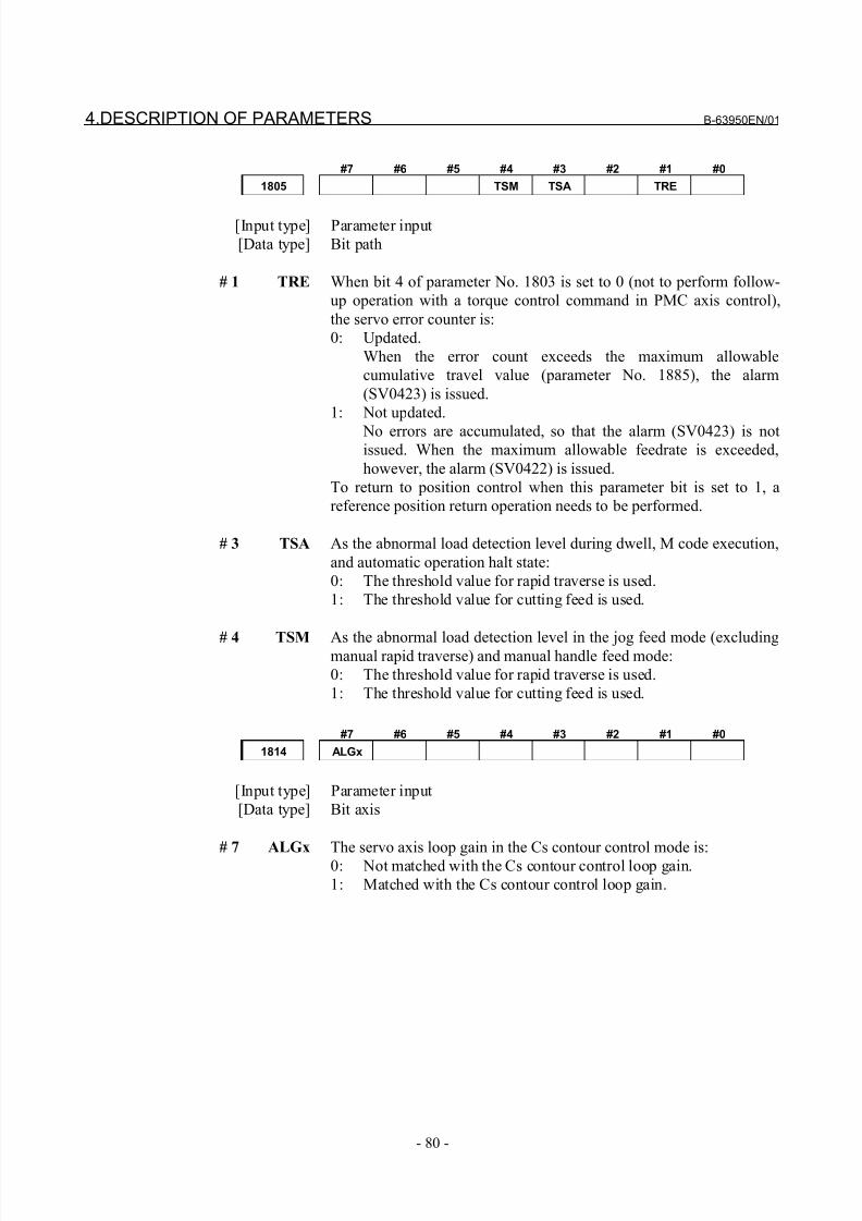
8/21/2019 30i Parameter Manual
http://slidepdf.com/reader/full/30i-parameter-manual 92/493
4.DESCRIPTION OF PARAMETERS B-63950EN/01
- 80 -
#7 #6 #5 #4 #3 #2 #1 #0
1805 TSM TSA TRE
[Input type] Parameter input
[Data type] Bit path
# 1 TRE When bit 4 of parameter No. 1803 is set to 0 (not to perform follow-
up operation with a torque control command in PMC axis control),
the servo error counter is:
0: Updated.
When the error count exceeds the maximum allowable
cumulative travel value (parameter No. 1885), the alarm
(SV0423) is issued.
1: Not updated.
No errors are accumulated, so that the alarm (SV0423) is notissued. When the maximum allowable feedrate is exceeded,
however, the alarm (SV0422) is issued.
To return to position control when this parameter bit is set to 1, a
reference position return operation needs to be performed.
# 3 TSA As the abnormal load detection level during dwell, M code execution,
and automatic operation halt state:
0: The threshold value for rapid traverse is used.
1: The threshold value for cutting feed is used.
# 4 TSM As the abnormal load detection level in the jog feed mode (excludingmanual rapid traverse) and manual handle feed mode:
0: The threshold value for rapid traverse is used.
1: The threshold value for cutting feed is used.
#7 #6 #5 #4 #3 #2 #1 #0
1814 ALGx
[Input type] Parameter input
[Data type] Bit axis
# 7 ALGx The servo axis loop gain in the Cs contour control mode is:
0: Not matched with the Cs contour control loop gain.
1: Matched with the Cs contour control loop gain.
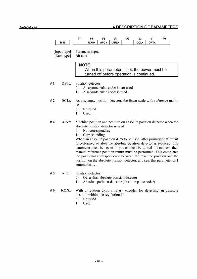
8/21/2019 30i Parameter Manual
http://slidepdf.com/reader/full/30i-parameter-manual 93/493
B-63950EN/01 4.DESCRIPTION OF PARAMETERS
- 81 -
#7 #6 #5 #4 #3 #2 #1 #0
1815 RONx APCx APZx DCLx OPTx
[Input type] Parameter input
[Data type] Bit axis
NOTEWhen this parameter is set, the power must beturned off before operation is continued.
# 1 OPTx Position detector
0: A separate pulse coder is not used.
1: A separate pulse coder is used.
# 2 DCLx As a separate position detector, the linear scale with reference marks
is:
0: Not used.
1: Used.
# 4 APZx Machine position and position on absolute position detector when the
absolute position detector is used
0: Not corresponding
1: Corresponding
When an absolute position detector is used, after primary adjustment
is performed or after the absolute position detector is replaced, this
parameter must be set to 0, power must be turned off and on, thenmanual reference position return must be performed. This completes
the positional correspondence between the machine position and the
position on the absolute position detector, and sets this parameter to 1
automatically.
# 5 APCx Position detector
0: Other than absolute position detector
1: Absolute position detector (absolute pulse coder)
# 6 RONx With a rotation axis, a rotary encoder for detecting an absolute
position within one revolution is:0: Not used.
1: Used.
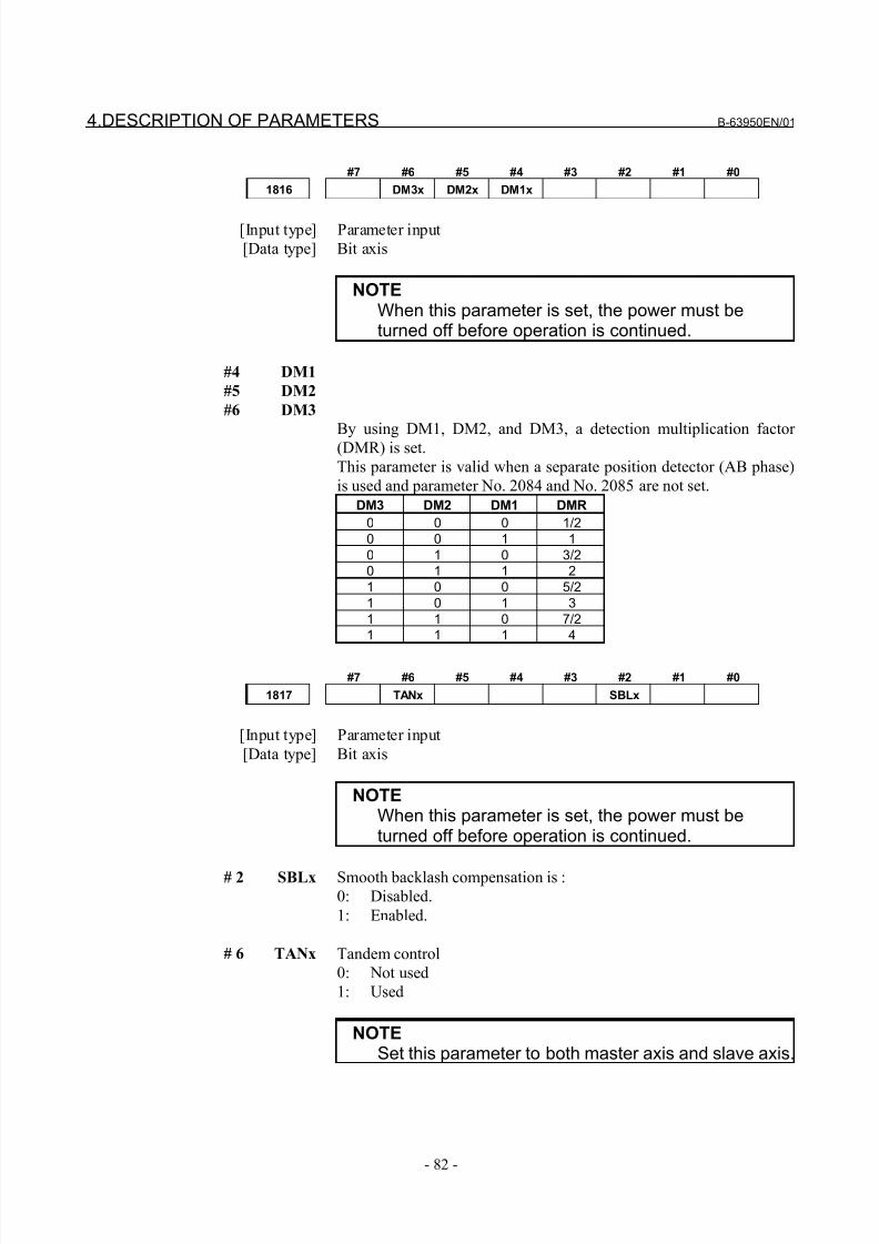
8/21/2019 30i Parameter Manual
http://slidepdf.com/reader/full/30i-parameter-manual 94/493
4.DESCRIPTION OF PARAMETERS B-63950EN/01
- 82 -
#7 #6 #5 #4 #3 #2 #1 #0
1816 DM3x DM2x DM1x
[Input type] Parameter input
[Data type] Bit axis
NOTEWhen this parameter is set, the power must beturned off before operation is continued.
#4 DM1
#5 DM2
#6 DM3
By using DM1, DM2, and DM3, a detection multiplication factor (DMR) is set.
This parameter is valid when a separate position detector (AB phase)
is used and parameter No. 2084 and No. 2085 are not set.
DM3 DM2 DM1 DMR
0 0 0 1/2
0 0 1 1
0 1 0 3/2
0 1 1 2
1 0 0 5/2
1 0 1 3
1 1 0 7/2
1 1 1 4
#7 #6 #5 #4 #3 #2 #1 #0
1817 TANx SBLx
[Input type] Parameter input
[Data type] Bit axis
NOTEWhen this parameter is set, the power must beturned off before operation is continued.
# 2 SBLx Smooth backlash compensation is :0: Disabled.
1: Enabled.
# 6 TANx Tandem control
0: Not used
1: Used
NOTESet this parameter to both master axis and slave axis.
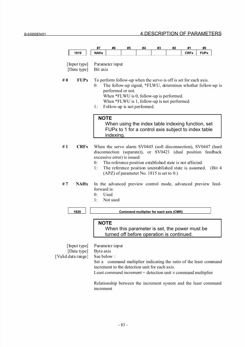
8/21/2019 30i Parameter Manual
http://slidepdf.com/reader/full/30i-parameter-manual 95/493
B-63950EN/01 4.DESCRIPTION OF PARAMETERS
- 83 -
#7 #6 #5 #4 #3 #2 #1 #0
1819 NAHx CRFx FUPx
[Input type] Parameter input
[Data type] Bit axis
# 0 FUPx To perform follow-up when the servo is off is set for each axis.
0: The follow-up signal, *FLWU, determines whether follow-up is
performed or not.
When *FLWU is 0, follow-up is performed.
When *FLWU is 1, follow-up is not performed.
1: Follow-up is not performed.
NOTEWhen using the index table indexing function, setFUPx to 1 for a control axis subject to index tableindexing.
# 1 CRFx When the servo alarm SV0445 (soft disconnection), SV0447 (hard
disconnection (separate)), or SV0421 (dual position feedback
excessive error) is issued:
0: The reference position established state is not affected.
1: The reference position unestablished state is assumed. (Bit 4
(APZ) of parameter No. 1815 is set to 0.)
# 7 NAHx In the advanced preview control mode, advanced preview feed-forward is:
0: Used
1: Not used
1820 Command multiplier for each axis (CMR)
NOTEWhen this parameter is set, the power must beturned off before operation is continued.
[Input type] Parameter input
[Data type] Byte axis
[Valid data range] See below :
Set a command multiplier indicating the ratio of the least command
increment to the detection unit for each axis.
Least command increment = detection unit × command multiplier
Relationship between the increment system and the least command
increment
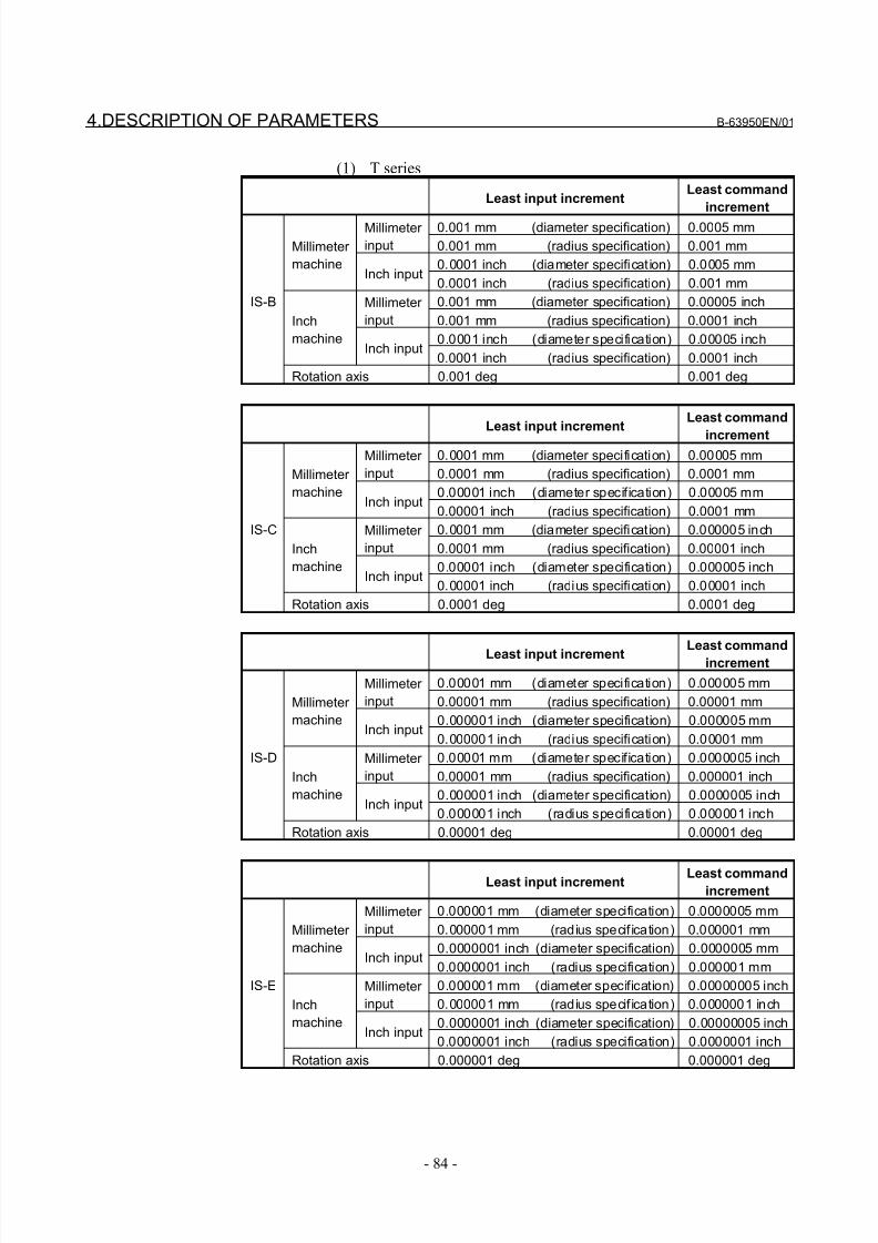
8/21/2019 30i Parameter Manual
http://slidepdf.com/reader/full/30i-parameter-manual 96/493
4.DESCRIPTION OF PARAMETERS B-63950EN/01
- 84 -
(1) T series
Least input incrementLeast command
increment
0.001 mm (diameter specification) 0.0005 mmMillimeter
input 0.001 mm (radius specification) 0.001 mm
0.0001 inch (diameter specification) 0.0005 mm
Millimeter
machineInch input
0.0001 inch (radius specification) 0.001 mm
0.001 mm (diameter specification) 0.00005 inchMillimeter
input 0.001 mm (radius specification) 0.0001 inch
0.0001 inch (diameter specification) 0.00005 inch
Inch
machineInch input
0.0001 inch (radius specification) 0.0001 inch
IS-B
Rotation axis 0.001 deg 0.001 deg
Least input incrementLeast command
increment0.0001 mm (diameter specification) 0.00005 mmMillimeter
input 0.0001 mm (radius specification) 0.0001 mm
0.00001 inch (diameter specification) 0.00005 mm
Millimeter
machineInch input
0.00001 inch (radius specification) 0.0001 mm
0.0001 mm (diameter specification) 0.000005 inchMillimeter
input 0.0001 mm (radius specification) 0.00001 inch
0.00001 inch (diameter specification) 0.000005 inch
Inch
machineInch input
0.00001 inch (radius specification) 0.00001 inch
IS-C
Rotation axis 0.0001 deg 0.0001 deg
Least input incrementLeast command
increment
0.00001 mm (diameter specification) 0.000005 mmMillimeter
input 0.00001 mm (radius specification) 0.00001 mm
0.000001 inch (diameter specification) 0.000005 mm
Millimeter
machineInch input
0.000001 inch (radius specification) 0.00001 mm
0.00001 mm (diameter specification) 0.0000005 inchMillimeter
input 0.00001 mm (radius specification) 0.000001 inch
0.000001 inch (diameter specification) 0.0000005 inch
Inch
machineInch input
0.000001 inch (radius specification) 0.000001 inch
IS-D
Rotation axis 0.00001 deg 0.00001 deg
Least input increment Least commandincrement
0.000001 mm (diameter specification) 0.0000005 mmMillimeter
input 0.000001 mm (radius specif ication) 0.000001 mm
0.0000001 inch (diameter specification) 0.0000005 mm
Millimeter
machineInch input
0.0000001 inch (radius specification) 0.000001 mm
0.000001 mm (diameter specification) 0.00000005 inchMillimeter
input 0.000001 mm (radius specif ication) 0.0000001 inch
0.0000001 inch (diameter specification) 0.00000005 inch
Inch
machineInch input
0.0000001 inch (radius specification) 0.0000001 inch
IS-E
Rotation axis 0.000001 deg 0.000001 deg
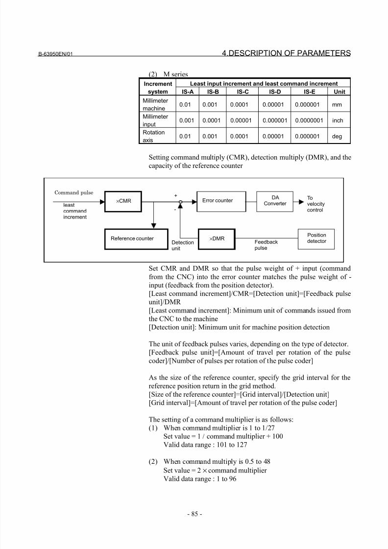
8/21/2019 30i Parameter Manual
http://slidepdf.com/reader/full/30i-parameter-manual 97/493
B-63950EN/01 4.DESCRIPTION OF PARAMETERS
- 85 -
(2) M series
Least input increment and least command incrementIncrement
system IS-A IS-B IS-C IS-D IS-E Unit
Millimeter
machine0.01 0.001 0.0001 0.00001 0.000001 mm
Millimeter
input0.001 0.0001 0.00001 0.000001 0.0000001 inch
Rotation
axis0.01 0.001 0.0001 0.00001 0.000001 deg
Setting command multiply (CMR), detection multiply (DMR), and the
capacity of the reference counter
leastcommandincrement
×CMR Error counter DA
Converter
×DMRPositiondetector
Reference counter
Command pulse
Feedbackpulse
Detectionunit
Tovelocitycontrol-
+
Set CMR and DMR so that the pulse weight of + input (command
from the CNC) into the error counter matches the pulse weight of -
input (feedback from the position detector).[Least command increment]/CMR=[Detection unit]=[Feedback pulse
unit]/DMR
[Least command increment]: Minimum unit of commands issued from
the CNC to the machine
[Detection unit]: Minimum unit for machine position detection
The unit of feedback pulses varies, depending on the type of detector.
[Feedback pulse unit]=[Amount of travel per rotation of the pulse
coder]/[Number of pulses per rotation of the pulse coder]
As the size of the reference counter, specify the grid interval for the
reference position return in the grid method.[Size of the reference counter]=[Grid interval]/[Detection unit]
[Grid interval]=[Amount of travel per rotation of the pulse coder]
The setting of a command multiplier is as follows:
(1) When command multiplier is 1 to 1/27
Set value = 1 / command multiplier + 100
Valid data range : 101 to 127
(2) When command multiply is 0.5 to 48
Set value = 2 × command multiplier
Valid data range : 1 to 96
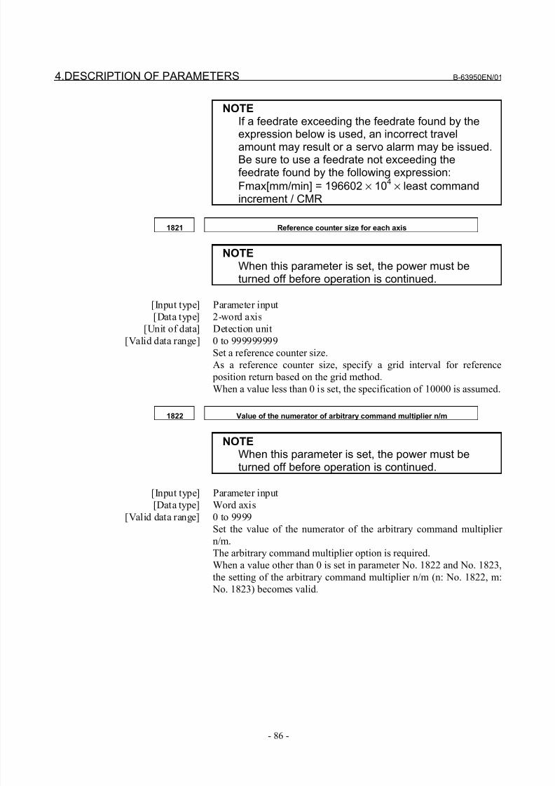
8/21/2019 30i Parameter Manual
http://slidepdf.com/reader/full/30i-parameter-manual 98/493
4.DESCRIPTION OF PARAMETERS B-63950EN/01
- 86 -
NOTEIf a feedrate exceeding the feedrate found by the
expression below is used, an incorrect travelamount may result or a servo alarm may be issued.Be sure to use a feedrate not exceeding thefeedrate found by the following expression:
Fmax[mm/min] = 196602 × 104 × least command
increment / CMR
1821 Reference counter size for each axis
NOTEWhen this parameter is set, the power must be
turned off before operation is continued.
[Input type] Parameter input
[Data type] 2-word axis
[Unit of data] Detection unit
[Valid data range] 0 to 999999999
Set a reference counter size.
As a reference counter size, specify a grid interval for reference
position return based on the grid method.
When a value less than 0 is set, the specification of 10000 is assumed.
1822 Value of the numerator of arbitrary command multiplier n/m
NOTEWhen this parameter is set, the power must beturned off before operation is continued.
[Input type] Parameter input
[Data type] Word axis
[Valid data range] 0 to 9999
Set the value of the numerator of the arbitrary command multiplier
n/m.
The arbitrary command multiplier option is required.When a value other than 0 is set in parameter No. 1822 and No. 1823,
the setting of the arbitrary command multiplier n/m (n: No. 1822, m:
No. 1823) becomes valid.
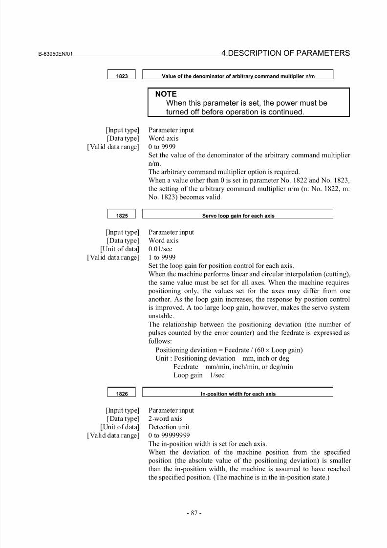
8/21/2019 30i Parameter Manual
http://slidepdf.com/reader/full/30i-parameter-manual 99/493
B-63950EN/01 4.DESCRIPTION OF PARAMETERS
- 87 -
1823 Value of the denominator of arbitrary command multiplier n/m
NOTEWhen this parameter is set, the power must beturned off before operation is continued.
[Input type] Parameter input
[Data type] Word axis
[Valid data range] 0 to 9999
Set the value of the denominator of the arbitrary command multiplier
n/m.
The arbitrary command multiplier option is required.
When a value other than 0 is set in parameter No. 1822 and No. 1823,
the setting of the arbitrary command multiplier n/m (n: No. 1822, m: No. 1823) becomes valid.
1825 Servo loop gain for each axis
[Input type] Parameter input
[Data type] Word axis
[Unit of data] 0.01/sec
[Valid data range] 1 to 9999
Set the loop gain for position control for each axis.
When the machine performs linear and circular interpolation (cutting),
the same value must be set for all axes. When the machine requires
positioning only, the values set for the axes may differ from one
another. As the loop gain increases, the response by position control
is improved. A too large loop gain, however, makes the servo system
unstable.
The relationship between the positioning deviation (the number of
pulses counted by the error counter) and the feedrate is expressed as
follows:
Positioning deviation = Feedrate / (60 × Loop gain)
Unit : Positioning deviation mm, inch or deg
Feedrate mm/min, inch/min, or deg/min
Loop gain 1/sec
1826 In-position width for each axis
[Input type] Parameter input
[Data type] 2-word axis
[Unit of data] Detection unit
[Valid data range] 0 to 99999999
The in-position width is set for each axis.
When the deviation of the machine position from the specified
position (the absolute value of the positioning deviation) is smaller
than the in-position width, the machine is assumed to have reached
the specified position. (The machine is in the in-position state.)
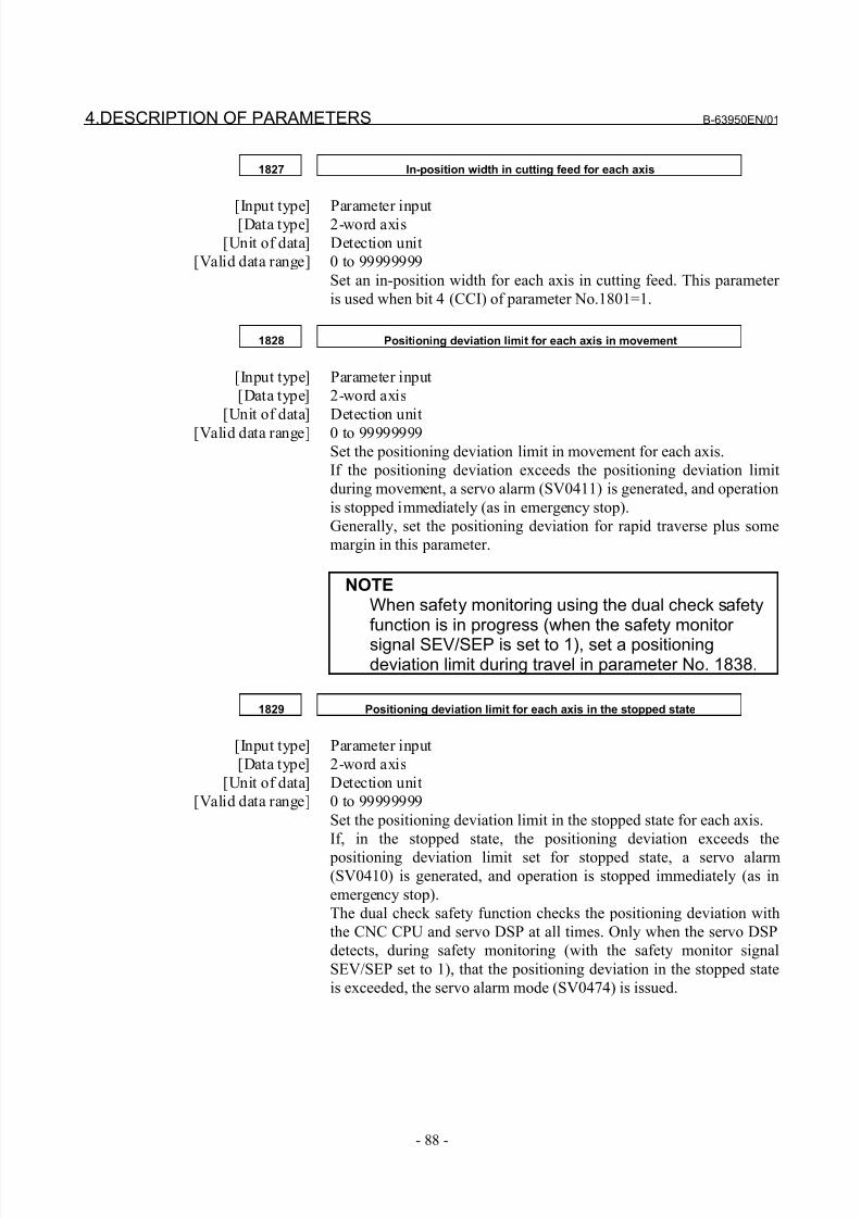
8/21/2019 30i Parameter Manual
http://slidepdf.com/reader/full/30i-parameter-manual 100/493
4.DESCRIPTION OF PARAMETERS B-63950EN/01
- 88 -
1827 In-position width in cutting feed for each axis
[Input type] Parameter input[Data type] 2-word axis
[Unit of data] Detection unit
[Valid data range] 0 to 99999999
Set an in-position width for each axis in cutting feed. This parameter
is used when bit 4 (CCI) of parameter No.1801=1.
1828 Positioning deviation limit for each axis in movement
[Input type] Parameter input
[Data type] 2-word axis
[Unit of data] Detection unit
[Valid data range] 0 to 99999999
Set the positioning deviation limit in movement for each axis.
If the positioning deviation exceeds the positioning deviation limit
during movement, a servo alarm (SV0411) is generated, and operation
is stopped immediately (as in emergency stop).
Generally, set the positioning deviation for rapid traverse plus some
margin in this parameter.
NOTEWhen safety monitoring using the dual check safetyfunction is in progress (when the safety monitor
signal SEV/SEP is set to 1), set a positioningdeviation limit during travel in parameter No. 1838.
1829 Positioning deviation limit for each axis in the stopped state
[Input type] Parameter input
[Data type] 2-word axis
[Unit of data] Detection unit
[Valid data range] 0 to 99999999
Set the positioning deviation limit in the stopped state for each axis.
If, in the stopped state, the positioning deviation exceeds the
positioning deviation limit set for stopped state, a servo alarm(SV0410) is generated, and operation is stopped immediately (as in
emergency stop).
The dual check safety function checks the positioning deviation with
the CNC CPU and servo DSP at all times. Only when the servo DSP
detects, during safety monitoring (with the safety monitor signal
SEV/SEP set to 1), that the positioning deviation in the stopped state
is exceeded, the servo alarm mode (SV0474) is issued.
8/21/2019 30i Parameter Manual
http://slidepdf.com/reader/full/30i-parameter-manual 101/493
B-63950EN/01 4.DESCRIPTION OF PARAMETERS
- 89 -
1830 Axis-by-axis positional deviation limit at servo-off time
[Input type] Parameter input[Data type] 2-word axis
[Unit of data] Detection unit
[Valid data range] 0 to 99999999
This parameter is used to set a positional deviation limit at servo-off
time, on an axis-by-axis basis.
If the value specified with this parameter is exceeded at servo-off time,
a servo alarm is issued to cause an immediate stop (same as an
emergency stop). Usually, set the same value as a positional deviation
at stop time.
1832 Feed stop positioning deviation for each axis
[Input type] Parameter input
[Data type] 2-word axis
[Unit of data] Detection unit
[Valid data range] 0 to 99999999
Set the feed stop positioning deviation for each axis.
If the positioning deviation exceeds the feed stop positioning
deviation during movement, pulse distribution and acceleration/
deceleration control are stopped temporarily. When the positioning
deviation drops to the feed stop positioning deviation or below, pulse
distribution and acceleration/deceleration control are resumed.
The feed stop function is used to reduce overshoot in acceleration/deceleration mainly by large servo motors.
Generally, set the middle value between the positioning deviation
limit during movement and the positioning deviation at rapid traverse
as the feed stop positioning deviation.
1836 Servo error amount where reference position return is possible
[Input type] Parameter input
[Data type] Word axis
[Unit of data] Detection unit
[Valid data range] 0 to 32767This parameter sets a servo error used to enable reference position
return.
In general, set this parameter to 0. (When 0 is set, 128 is assumed as
the default.)
If, during reference position return, such a feedrate as exceeding a set
value is not reached even once before the limit switch for deceleration
is released (the deceleration signal (*DEC) is set to 1 again), the
alarm (PS0090) "REFERENCE POSITION RETURN FAILURE" is
issued.
If, during reference position return, such a feedrate as exceeding a set
servo error amount is not reached even once before the limit switch
for deceleration is released (the deceleration signal is set to 1 again),the alarm (PS0090) "REFERENCE POSITION RETURN FAILURE"
is issued.
8/21/2019 30i Parameter Manual
http://slidepdf.com/reader/full/30i-parameter-manual 102/493
4.DESCRIPTION OF PARAMETERS B-63950EN/01
- 90 -
1844
Distance to the first grid point after the deceleration dog is turned off in the
case where the reference position shift amount of the reference position
shift function is 0
NOTEWhen this parameter is set, the power must beturned off before operation is continued.
[Input type] Parameter input
[Data type] 2-word axis
[Unit of data] Detection unit
[Valid data range] -999999999 to 999999999
Set a distance to the first grid point after the deceleration dog is
turned off in the case where the reference position shift amount (No.1850) is 0.
NOTEThis parameter is automatically set if referenceposition return is performed when bit 4 (SFDx) of parameter No. 1008 is set to 1, the distance to thefirst grid point after the deceleration dog is turnedoff (parameter No. 1844) is set to 0, and thereference position shift amount (parameter No.1850) is set to 0.
Do not change an automatically set value.
1846 Distance for starting the second stage of smooth backlash compensation
[Input type] Parameter input
[Data type] 2-word axis
[Unit of data] Detection unit
[Valid data range] 0 to 999999999
For each axis, set the distance from the point where the axis
movement direction is reversed to the point where the second stage of
smooth backlash compensation is started.
1847 Distance for ending the second stage of smooth backlash compensation
[Input type] Parameter input
[Data type] 2-word axis
[Unit of data] Detection unit
[Valid data range] 0 to 999999999
For each axis, set the distance from the point where the axis
movement direction is reversed to the point where the second stage of
smooth backlash compensation is ended.
8/21/2019 30i Parameter Manual
http://slidepdf.com/reader/full/30i-parameter-manual 103/493
B-63950EN/01 4.DESCRIPTION OF PARAMETERS
- 91 -
1848 Value of the first stage of smooth backlash compensation
[Input type] Parameter input[Data type] Word axis
[Unit of data] Detection unit
[Valid data range] -9999 to 9999
Set the value of the first stage of smooth backlash compensation for
each axis.
1850 Grid shift and reference position shift for each axis
NOTEWhen this parameter is set, the power must be
turned off before operation is continued.
[Input type] Parameter input
[Data type] 2-word axis
[Unit of data] Detection unit
[Valid data range] 0 to 99999999
To shift the reference position, the grid can be shifted by the amount
set in this parameter. Up to the maximum value counted by the
reference counter can be specified as the grid shift.
In case of parameter SFDx(No.1008#4) is 0: Grid shift
In case of parameter SFDx(No.1008#4) is 1: Reference point shift
NOTEFor setting the reference position without dogs, onlythe grid shift function can be used.(The reference position shift function cannot beused.)
1851 Backlash compensating value for each axis
[Input type] Parameter input
[Data type] Word axis
[Unit of data] Detection unit[Valid data range] -9999 to 9999
Set the backlash compensating value for each axis.
When the machine moves in a direction opposite to the reference
position return direction after the power is turned on, the first
backlash compensation is performed.
8/21/2019 30i Parameter Manual
http://slidepdf.com/reader/full/30i-parameter-manual 104/493
4.DESCRIPTION OF PARAMETERS B-63950EN/01
- 92 -
1852 Backlash compensating value used for rapid traverse for each axis
[Input type] Parameter input[Data type] Word axis
[Unit of data] Detection unit
[Valid data range] -9999 to 9999
Set the backlash compensating value used in rapid traverse for each
axis. (This parameter is valid when RBK, #4 of parameter 1800, is set
to 1.) More precise machining can be performed by changing the
backlash compensating value depending on the feedrate, the cutting
feed or the rapid traverse positioning. Let the measured backlash at
cutting feed be A and the measured backlash at rapid traverse be B.
The backlash compensating value is shown below depending on the
change of feedrate (cutting feed or rapid traverse) and the change of
the direction of movement.
Change of feedrate
Change of
direction of movement
Cutting feed to
cutting feed
Rapid
traverse to
rapid traverse
Rapid
traverse to
cutting feed
Cutting feed
to rapid
traverse
Same direction 0 0 ±α ±(-α)
Opposite direction ± A ±B ±(B+α) ±(B+α)
NOTE
1 α=(A-B)/22 The positive or negative direction for compensating
values is the direction of movement.
1880 Abnormal load detection alarm timer
[Input type] Parameter input
[Data type] Word path
[Unit of data] msec
[Valid data range] 0 to 32767
This parameter sets the time from the detection of an abnormal load
until a servo alarm is issued.
When 0 is set, however, the specification of 200 msec is assumed.
1881 Group number when an abnormal load is detected
[Input type] Parameter input
[Data type] Byte axis
[Valid data range] 0 to 32
This parameter sets the group number of each axis, used when an
abnormal load is detected.
If an abnormal load is detected for an axis, only the movement along
the axes of the group containing the axis with the abnormal load is
stopped. If 0 is set for an axis, movement along that axis is stopped
whenever an abnormal load is detected for any axis.This parameter is enabled when the parameter ANA (bit 5 of
No.1804) is 1.
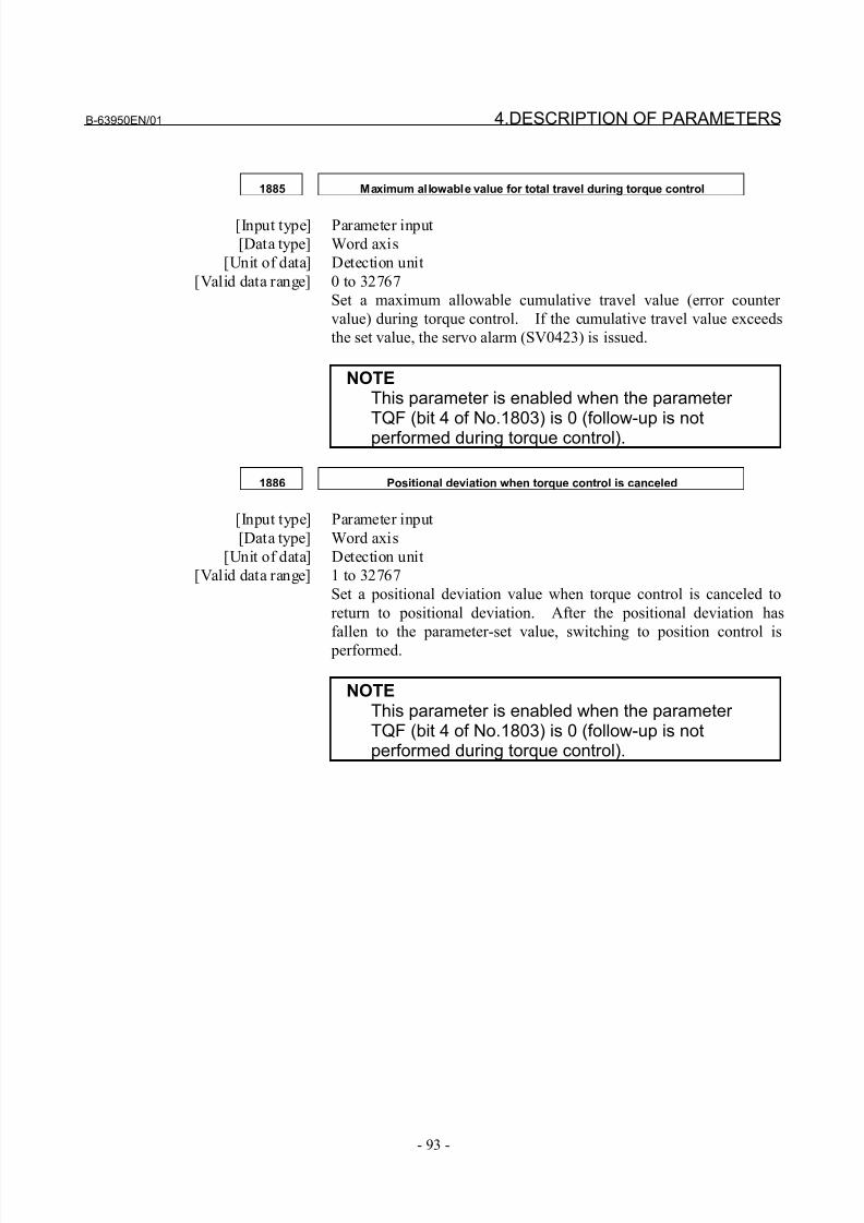
8/21/2019 30i Parameter Manual
http://slidepdf.com/reader/full/30i-parameter-manual 105/493
B-63950EN/01 4.DESCRIPTION OF PARAMETERS
- 93 -
1885 Maximum allowable value for total travel during torque control
[Input type] Parameter input
[Data type] Word axis
[Unit of data] Detection unit
[Valid data range] 0 to 32767
Set a maximum allowable cumulative travel value (error counter
value) during torque control. If the cumulative travel value exceeds
the set value, the servo alarm (SV0423) is issued.
NOTEThis parameter is enabled when the parameter TQF (bit 4 of No.1803) is 0 (follow-up is notperformed during torque control).
1886 Positional deviation when torque control is canceled
[Input type] Parameter input
[Data type] Word axis
[Unit of data] Detection unit
[Valid data range] 1 to 32767
Set a positional deviation value when torque control is canceled to
return to positional deviation. After the positional deviation has
fallen to the parameter-set value, switching to position control is
performed.
NOTEThis parameter is enabled when the parameter TQF (bit 4 of No.1803) is 0 (follow-up is notperformed during torque control).
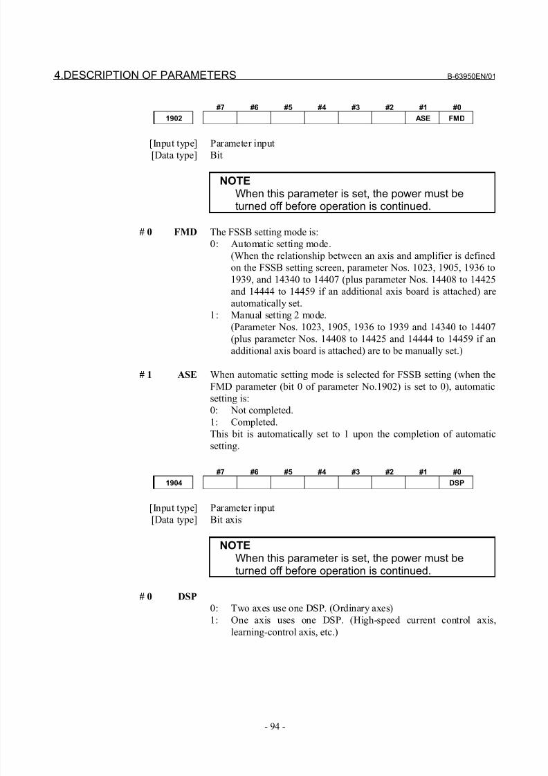
8/21/2019 30i Parameter Manual
http://slidepdf.com/reader/full/30i-parameter-manual 106/493
4.DESCRIPTION OF PARAMETERS B-63950EN/01
- 94 -
#7 #6 #5 #4 #3 #2 #1 #0
1902 ASE FMD
[Input type] Parameter input
[Data type] Bit
NOTEWhen this parameter is set, the power must beturned off before operation is continued.
# 0 FMD The FSSB setting mode is:
0: Automatic setting mode.
(When the relationship between an axis and amplifier is defined
on the FSSB setting screen, parameter Nos. 1023, 1905, 1936 to1939, and 14340 to 14407 (plus parameter Nos. 14408 to 14425
and 14444 to 14459 if an additional axis board is attached) are
automatically set.
1: Manual setting 2 mode.
(Parameter Nos. 1023, 1905, 1936 to 1939 and 14340 to 14407
(plus parameter Nos. 14408 to 14425 and 14444 to 14459 if an
additional axis board is attached) are to be manually set.)
# 1 ASE When automatic setting mode is selected for FSSB setting (when the
FMD parameter (bit 0 of parameter No.1902) is set to 0), automatic
setting is:
0: Not completed.1: Completed.
This bit is automatically set to 1 upon the completion of automatic
setting.
#7 #6 #5 #4 #3 #2 #1 #0
1904 DSP
[Input type] Parameter input
[Data type] Bit axis
NOTEWhen this parameter is set, the power must beturned off before operation is continued.
# 0 DSP
0: Two axes use one DSP. (Ordinary axes)
1: One axis uses one DSP. (High-speed current control axis,
learning-control axis, etc.)
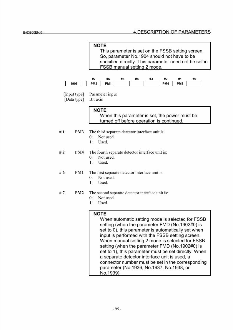
8/21/2019 30i Parameter Manual
http://slidepdf.com/reader/full/30i-parameter-manual 107/493
B-63950EN/01 4.DESCRIPTION OF PARAMETERS
- 95 -
NOTEThis parameter is set on the FSSB setting screen.
So, parameter No.1904 should not have to bespecified directly. This parameter need not be set inFSSB manual setting 2 mode.
#7 #6 #5 #4 #3 #2 #1 #0
1905 PM2 PM1 PM4 PM3
[Input type] Parameter input
[Data type] Bit axis
NOTE
When this parameter is set, the power must beturned off before operation is continued.
# 1 PM3 The third separate detector interface unit is:
0: Not used.
1: Used.
# 2 PM4 The fourth separate detector interface unit is:
0: Not used.
1: Used.
# 6 PM1 The first separate detector interface unit is:0: Not used.
1: Used.
# 7 PM2 The second separate detector interface unit is:
0: Not used.
1: Used.
NOTEWhen automatic setting mode is selected for FSSBsetting (when the parameter FMD (No.1902#0) is
set to 0), this parameter is automatically set wheninput is performed with the FSSB setting screen.When manual setting 2 mode is selected for FSSBsetting (when the parameter FMD (No.1902#0) isset to 1), this parameter must be set directly. Whena separate detector interface unit is used, aconnector number must be set in the correspondingparameter (No.1936, No.1937, No.1938, or No.1939).
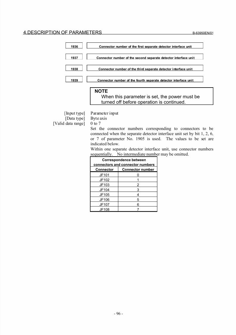
8/21/2019 30i Parameter Manual
http://slidepdf.com/reader/full/30i-parameter-manual 108/493
4.DESCRIPTION OF PARAMETERS B-63950EN/01
- 96 -
1936 Connector number of the first separate detector interface unit
1937 Connector number of the second separate detector interface unit
1938 Connector number of the third separate detector interface unit
1939 Connector number of the fourth separate detector interface unit
NOTEWhen this parameter is set, the power must beturned off before operation is continued.
[Input type] Parameter input
[Data type] Byte axis[Valid data range] 0 to 7
Set the connector numbers corresponding to connectors to be
connected when the separate detector interface unit set by bit 1, 2, 6,
or 7 of parameter No. 1905 is used. The values to be set are
indicated below.
Within one separate detector interface unit, use connector numbers
sequentially. No intermediate number may be omitted.
Correspondence between
connectors and connector numbers
Connector Connector number
JF101 0JF102 1
JF103 2
JF104 3
JF105 4
JF106 5
JF107 6
JF108 7
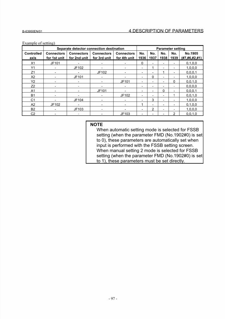
8/21/2019 30i Parameter Manual
http://slidepdf.com/reader/full/30i-parameter-manual 109/493
B-63950EN/01 4.DESCRIPTION OF PARAMETERS
- 97 -
Example of setting)
Separate detector connection destination Parameter setting
Controlled
axis
Connectors
for 1st unit
Connectors
for 2nd unit
Connectors
for 3rd unit
Connectors
for 4th unit
No.
1936
No.
1937
No.
1938
No.
1939
No.1905
(#7,#6,#2,#1)
X1 JF101 - - - 0 - - - 0,1,0,0
Y1 - JF102 - - - 1 - - 1,0,0,0
Z1 - - JF102 - - - 1 - 0,0,0,1
X2 - JF101 - - - 0 - - 1,0,0,0
Y2 - - - JF101 - - - 0 0,0,1,0
Z2 - - - - - - - - 0,0,0,0
A1 - - JF101 - - - 0 - 0,0,0,1
B1 - - - JF102 - - - 1 0,0,1,0
C1 - JF104 - - - 3 - - 1,0,0,0
A2 JF102 - - - 1 - - - 0,1,0,0
B2 - JF103 - - - 2 - - 1,0,0,0
C2 - - - JF103 - - - 2 0,0,1,0
NOTEWhen automatic setting mode is selected for FSSBsetting (when the parameter FMD (No.1902#0) is setto 0), these parameters are automatically set wheninput is performed with the FSSB setting screen.When manual setting 2 mode is selected for FSSBsetting (when the parameter FMD (No.1902#0) is setto 1), these parameters must be set directly.
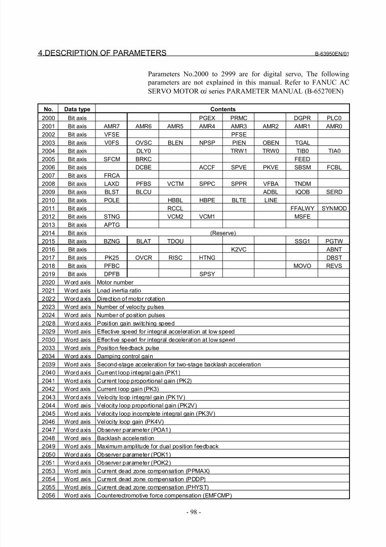
8/21/2019 30i Parameter Manual
http://slidepdf.com/reader/full/30i-parameter-manual 110/493
4.DESCRIPTION OF PARAMETERS B-63950EN/01
- 98 -
Parameters No.2000 to 2999 are for digital servo, The following
parameters are not explained in this manual. Refer to FANUC AC
SERVO MOTOR αi series PARAMETER MANUAL (B-65270EN)
No. Data type Contents
2000 Bit axis PGEX PRMC DGPR PLC0
2001 Bit axis AMR7 AMR6 AMR5 AMR4 AMR3 AMR2 AMR1 AMR0
2002 Bit axis VFSE PFSE
2003 Bit axis V0FS OVSC BLEN NPSP PIEN OBEN TGAL
2004 Bit axis DLY0 TRW1 TRW0 TIB0 TIA0
2005 Bit axis SFCM BRKC FEED
2006 Bit axis DCBE ACCF SPVE PKVE SBSM FCBL
2007 Bit axis FRCA
2008 Bit axis LAXD PFBS VCTM SPPC SPPR VFBA TNDM
2009 Bit axis BLST BLCU ADBL IQOB SERD2010 Bit axis POLE HBBL HBPE BLTE LINE
2011 Bit axis RCCL FFALWY SYNMOD
2012 Bit axis STNG VCM2 VCM1 MSFE
2013 Bit axis APTG
2014 Bit axis (Reserve)
2015 Bit axis BZNG BLAT TDOU SSG1 PGTW
2016 Bit axis K2VC ABNT
2017 Bit axis PK25 OVCR RISC HTNG DBST
2018 Bit axis PFBC MOVO REVS
2019 Bit axis DPFB SPSY
2020 Word axis Motor number
2021 Word axis Load inertia ratio
2022 Word axis Direction of motor rotation
2023 Word axis Number of velocity pulses
2024 Word axis Number of posit ion pulses
2028 Word axis Position gain switching speed
2029 Word axis Effective speed for integral acceleration at low speed
2030 Word axis Effective speed for integral deceleration at low speed
2033 Word axis Position feedback pulse
2034 Word axis Damping control gain
2039 Word axis Second-stage acceleration for two-stage backlash acceleration
2040 Word axis Current loop integral gain (PK1)
2041 Word axis Current loop proportional gain (PK2)2042 Word axis Current loop gain (PK3)
2043 Word axis Velocity loop integral gain (PK1V)
2044 Word axis Velocity loop proportional gain (PK2V)
2045 Word axis Velocity loop incomplete integral gain (PK3V)
2046 Word axis Velocity loop gain (PK4V)
2047 Word axis Observer parameter (POA1)
2048 Word axis Backlash acceleration
2049 Word axis Maximum amplitude for dual position feedback
2050 Word axis Observer parameter (POK1)
2051 Word axis Observer parameter (POK2)
2053 Word axis Current dead zone compensation (PPMAX)
2054 Word axis Current dead zone compensation (PDDP)2055 Word axis Current dead zone compensation (PHYST)
2056 Word axis Counterectromotive force compensation (EMFCMP)
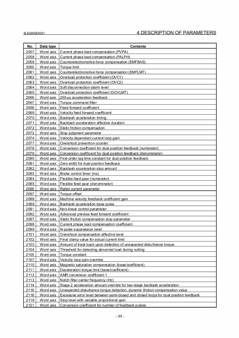
8/21/2019 30i Parameter Manual
http://slidepdf.com/reader/full/30i-parameter-manual 111/493
B-63950EN/01 4.DESCRIPTION OF PARAMETERS
- 99 -
No. Data type Contents
2057 Word axis Current phase lead compensation (PVPA)
2058 Word axis Current phase lead compensation (PALPH)
2059 Word axis Counterelectromotive force compensation (EMFBAS)
2060 Word axis Torque limit
2061 Word axis Counterelectromotive force compensation (EMFLMT)
2062 Word axis Overload protection coefficient (OVC1)
2063 Word axis Overload protection coefficient (OVC2)
2064 Word axis Soft disconnection alarm level
2065 Word axis Overload protection coefficient (OCVLMT)
2066 Word axis 250-µs acceleration feedback
2067 Word axis Torque command fi lter
2068 Word axis Feed forward coefficient
2069 Word axis Velocity feed forward coefficient
2070 Word axis Backlash acceleration timing2071 Word axis Backlash acceleration effective duration
2072 Word axis Static friction compensation
2073 Word axis Stop judgment parameter
2074 Word axis Velocity-dependent current loop gain
2077 Word axis Overshoot prevention counter
2078 Word axis Conversion coefficient for dual position feedback (numerator)
2079 Word axis Conversion coefficient for dual position feedback (denominator)
2080 Word axis First-order lag time constant for dual position feedback
2081 Word axis Zero width for dual position feedback
2082 Word axis Backlash acceleration stop amount
2083 Word axis Brake control timer (ms)
2084 Word axis Flexible feed gear (numerator)
2085 Word axis Flexible feed gear (denominator)
2086 Word axis Rated current parameter
2087 Word axis Torque offset
2088 Word axis Machine velocity feedback coefficient gain
2089 Word axis Backlash acceleration base pulse
2091 Word axis Non-linear control parameter
2092 Word axis Advanced preview feed forward coefficient
2097 Word axis Static friction compensation stop parameter
2098 Word axis Current phase lead compensation coefficient
2099 Word axis N-pulse suppression level
2101 Word axis Overshoot compensation effective level
2102 Word axis Final clamp value for actual current limit
2103 Word axis Amount of track back upon detection of unexpected disturbance torque
2104 Word axis Threshold for detecting abnormal load during cutting
2105 Word axis Torque constant
2107 Word axis Velocity loop gain override
2110 Word axis Magnetic saturation compensation (base/coefficient)
2111 Word axis Deceleration torque limit (base/coefficient)
2112 Word axis AMR conversion coefficient 1
2113 Word axis Notch filter center frequency (Hz)
2114 Word axis Stage 2 acceleration amount override for two-stage backlash acceleration
2116 Word axis Unexpected disturbance torque detection, dynamic friction compensation value
2118 Word axis Excessive error level between semi-closed and closed loops for dual position feedback2119 Word axis Stop level with variable proportional gain
2121 Word axis Conversion coefficient for number of feedback pulses
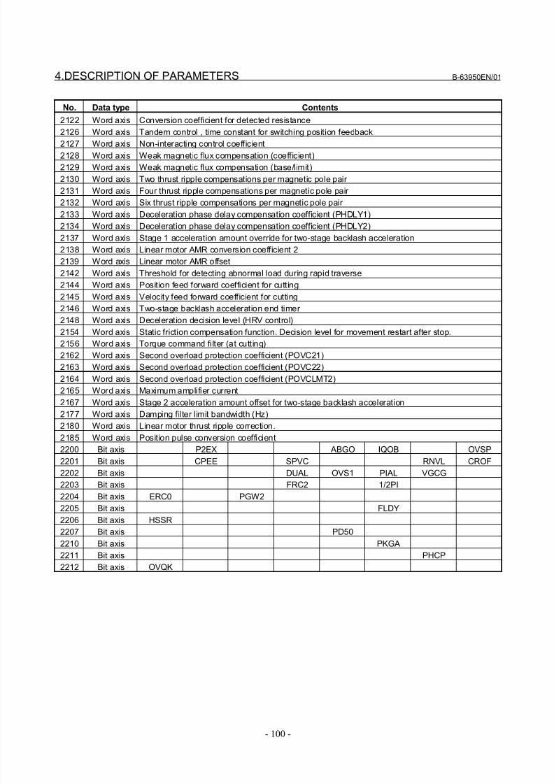
8/21/2019 30i Parameter Manual
http://slidepdf.com/reader/full/30i-parameter-manual 112/493
4.DESCRIPTION OF PARAMETERS B-63950EN/01
- 100 -
No. Data type Contents
2122 Word axis Conversion coefficient for detected resistance
2126 Word axis Tandem control , time constant for switching position feedback
2127 Word axis Non-interacting control coefficient
2128 Word axis Weak magnetic flux compensation (coefficient)
2129 Word axis Weak magnetic flux compensation (base/limit)
2130 Word axis Two thrust ripple compensations per magnetic pole pair
2131 Word axis Four thrust ripple compensations per magnetic pole pair
2132 Word axis Six thrust ripple compensations per magnetic pole pair
2133 Word axis Deceleration phase delay compensation coefficient (PHDLY1)
2134 Word axis Deceleration phase delay compensation coefficient (PHDLY2)
2137 Word axis Stage 1 acceleration amount override for two-stage backlash acceleration
2138 Word axis Linear motor AMR conversion coefficient 2
2139 Word axis Linear motor AMR offset
2142 Word axis Threshold for detecting abnormal load during rapid traverse2144 Word axis Position feed forward coefficient for cutting
2145 Word axis Velocity feed forward coefficient for cutting
2146 Word axis Two-stage backlash acceleration end timer
2148 Word axis Deceleration decision level (HRV control)
2154 Word axis Static friction compensation function. Decision level for movement restart after stop.
2156 Word axis Torque command filter (at cutting)
2162 Word axis Second overload protection coefficient (POVC21)
2163 Word axis Second overload protection coefficient (POVC22)
2164 Word axis Second overload protection coefficient (POVCLMT2)
2165 Word axis Maximum amplifier current
2167 Word axis Stage 2 acceleration amount offset for two-stage backlash acceleration
2177 Word axis Damping filter limit bandwidth (Hz)
2180 Word axis Linear motor thrust ripple correction.
2185 Word axis Position pulse conversion coefficient
2200 Bit axis P2EX ABGO IQOB OVSP
2201 Bit axis CPEE SPVC RNVL CROF
2202 Bit axis DUAL OVS1 PIAL VGCG
2203 Bit axis FRC2 1/2PI
2204 Bit axis ERC0 PGW2
2205 Bit axis FLDY
2206 Bit axis HSSR
2207 Bit axis PD50
2210 Bit axis PKGA
2211 Bit axis PHCP
2212 Bit axis OVQK
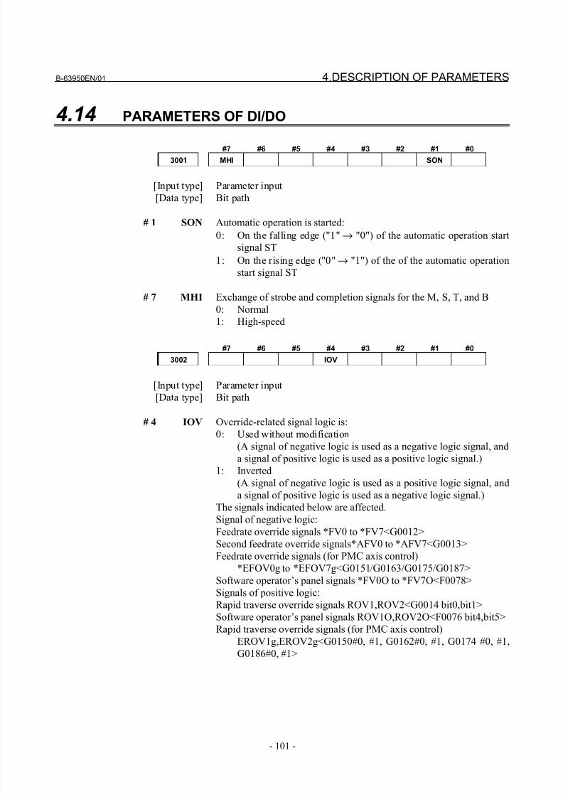
8/21/2019 30i Parameter Manual
http://slidepdf.com/reader/full/30i-parameter-manual 113/493
B-63950EN/01 4.DESCRIPTION OF PARAMETERS
- 101 -
4.14 PARAMETERS OF DI/DO
#7 #6 #5 #4 #3 #2 #1 #0
3001 MHI SON
[Input type] Parameter input
[Data type] Bit path
# 1 SON Automatic operation is started:
0: On the falling edge ("1" → "0") of the automatic operation start
signal ST
1: On the rising edge ("0" → "1") of the of the automatic operation
start signal ST
# 7 MHI Exchange of strobe and completion signals for the M, S, T, and B
0: Normal
1: High-speed
#7 #6 #5 #4 #3 #2 #1 #0
3002 IOV
[Input type] Parameter input
[Data type] Bit path
# 4 IOV Override-related signal logic is:0: Used without modification
(A signal of negative logic is used as a negative logic signal, and
a signal of positive logic is used as a positive logic signal.)
1: Inverted
(A signal of negative logic is used as a positive logic signal, and
a signal of positive logic is used as a negative logic signal.)
The signals indicated below are affected.
Signal of negative logic:
Feedrate override signals *FV0 to *FV7<G0012>
Second feedrate override signals*AFV0 to *AFV7<G0013>
Feedrate override signals (for PMC axis control)*EFOV0g to *EFOV7g<G0151/G0163/G0175/G0187>
Software operator’s panel signals *FV0O to *FV7O<F0078>
Signals of positive logic:
Rapid traverse override signals ROV1,ROV2<G0014 bit0,bit1>
Software operator’s panel signals ROV1O,ROV2O<F0076 bit4,bit5>
Rapid traverse override signals (for PMC axis control)
EROV1g,EROV2g<G0150#0, #1, G0162#0, #1, G0174 #0, #1,
G0186#0, #1>
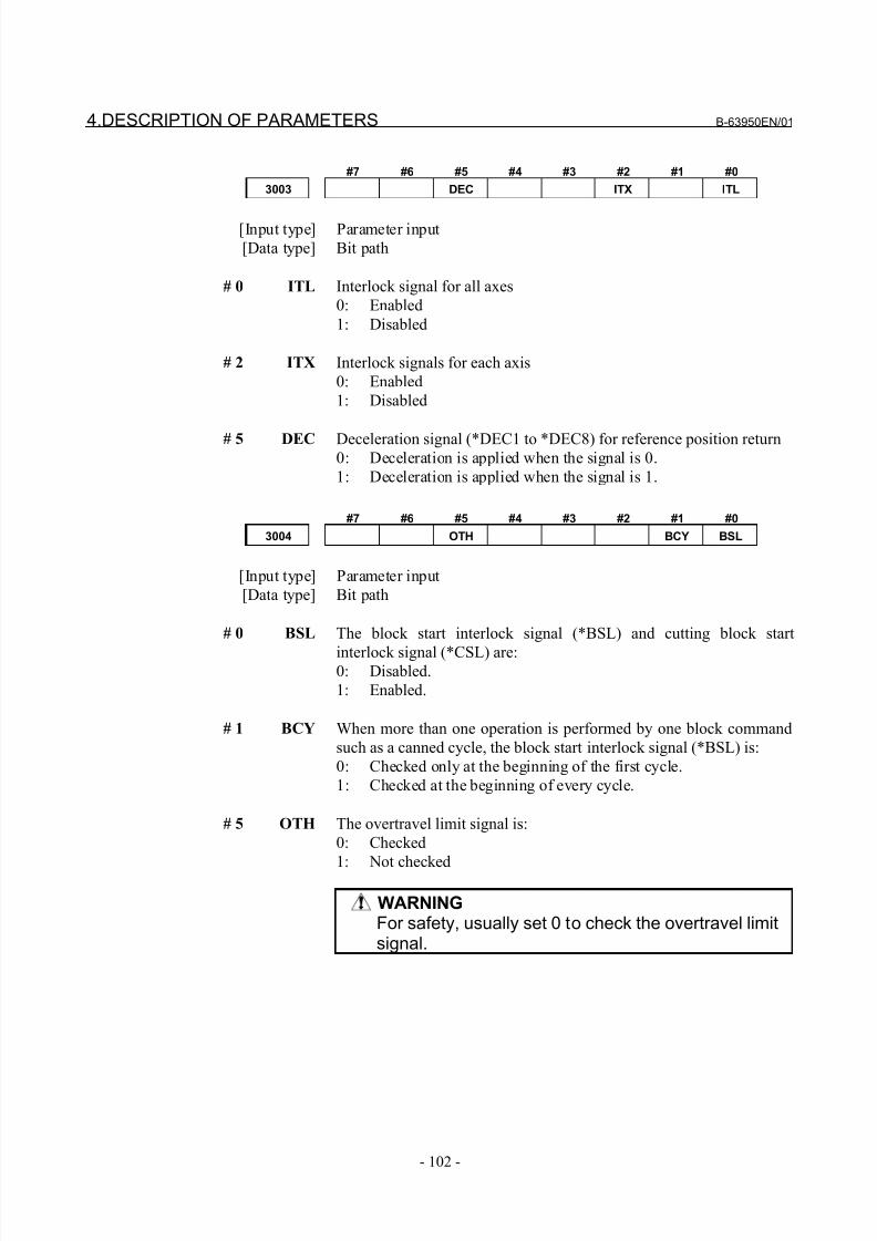
8/21/2019 30i Parameter Manual
http://slidepdf.com/reader/full/30i-parameter-manual 114/493
4.DESCRIPTION OF PARAMETERS B-63950EN/01
- 102 -
#7 #6 #5 #4 #3 #2 #1 #0
3003 DEC ITX ITL
[Input type] Parameter input
[Data type] Bit path
# 0 ITL Interlock signal for all axes
0: Enabled
1: Disabled
# 2 ITX Interlock signals for each axis
0: Enabled
1: Disabled
# 5 DEC Deceleration signal (*DEC1 to *DEC8) for reference position return0: Deceleration is applied when the signal is 0.
1: Deceleration is applied when the signal is 1.
#7 #6 #5 #4 #3 #2 #1 #0
3004 OTH BCY BSL
[Input type] Parameter input
[Data type] Bit path
# 0 BSL The block start interlock signal (*BSL) and cutting block start
interlock signal (*CSL) are:0: Disabled.
1: Enabled.
# 1 BCY When more than one operation is performed by one block command
such as a canned cycle, the block start interlock signal (*BSL) is:
0: Checked only at the beginning of the first cycle.
1: Checked at the beginning of every cycle.
# 5 OTH The overtravel limit signal is:
0: Checked
1: Not checked
WARNINGFor safety, usually set 0 to check the overtravel limitsignal.
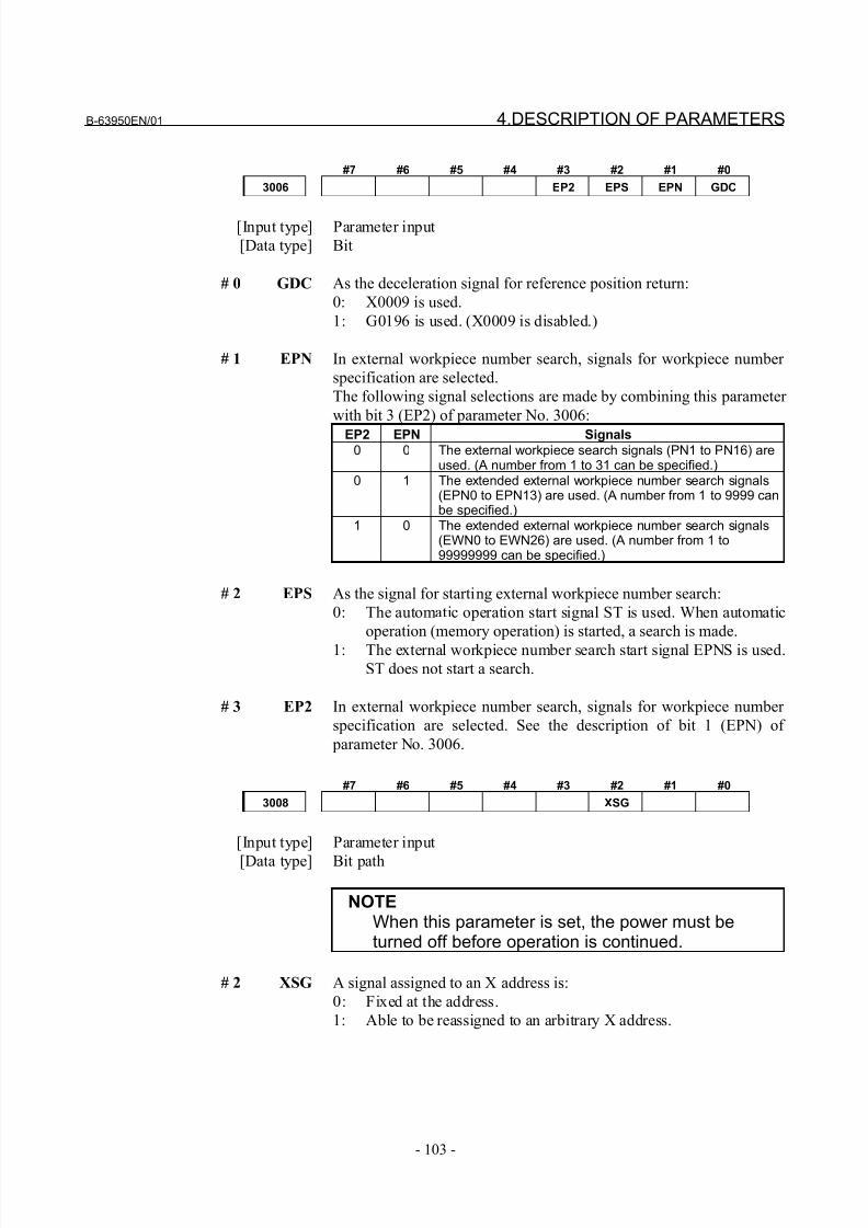
8/21/2019 30i Parameter Manual
http://slidepdf.com/reader/full/30i-parameter-manual 115/493
B-63950EN/01 4.DESCRIPTION OF PARAMETERS
- 103 -
#7 #6 #5 #4 #3 #2 #1 #0
3006 EP2 EPS EPN GDC
[Input type] Parameter input
[Data type] Bit
# 0 GDC As the deceleration signal for reference position return:
0: X0009 is used.
1: G0196 is used. (X0009 is disabled.)
# 1 EPN In external workpiece number search, signals for workpiece number
specification are selected.
The following signal selections are made by combining this parameter
with bit 3 (EP2) of parameter No. 3006:
EP2 EPN Signals0 0 The external workpiece search signals (PN1 to PN16) are
used. (A number from 1 to 31 can be specified.)0 1 The extended external workpiece number search signals
(EPN0 to EPN13) are used. (A number from 1 to 9999 canbe specified.)
1 0 The extended external workpiece number search signals(EWN0 to EWN26) are used. (A number from 1 to99999999 can be specified.)
# 2 EPS As the signal for starting external workpiece number search:
0: The automatic operation start signal ST is used. When automatic
operation (memory operation) is started, a search is made.
1: The external workpiece number search start signal EPNS is used.ST does not start a search.
# 3 EP2 In external workpiece number search, signals for workpiece number
specification are selected. See the description of bit 1 (EPN) of
parameter No. 3006.
#7 #6 #5 #4 #3 #2 #1 #0
3008 XSG
[Input type] Parameter input
[Data type] Bit path
NOTEWhen this parameter is set, the power must beturned off before operation is continued.
# 2 XSG A signal assigned to an X address is:
0: Fixed at the address.
1: Able to be reassigned to an arbitrary X address.
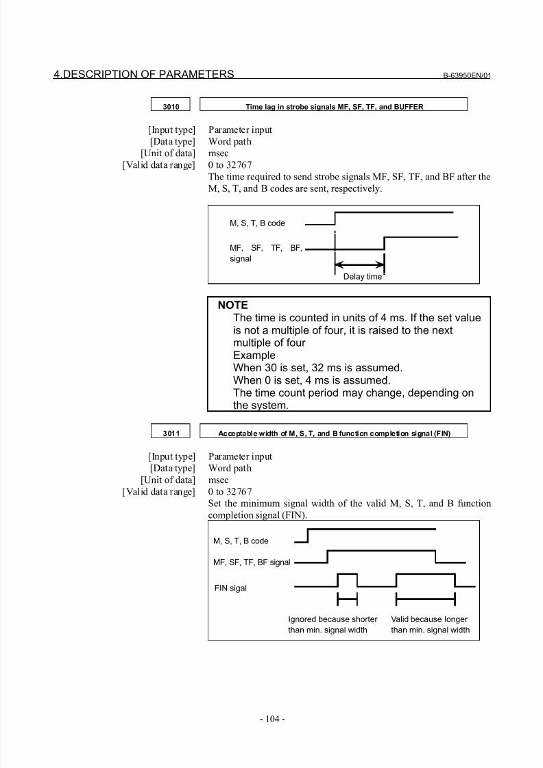
8/21/2019 30i Parameter Manual
http://slidepdf.com/reader/full/30i-parameter-manual 116/493
4.DESCRIPTION OF PARAMETERS B-63950EN/01
- 104 -
3010 Time lag in strobe signals MF, SF, TF, and BUFFER
[Input type] Parameter input[Data type] Word path
[Unit of data] msec
[Valid data range] 0 to 32767
The time required to send strobe signals MF, SF, TF, and BF after the
M, S, T, and B codes are sent, respectively.
M, S, T, B code
MF, SF, TF, BF,
signal
Delay time
NOTEThe time is counted in units of 4 ms. If the set valueis not a multiple of four, it is raised to the nextmultiple of four ExampleWhen 30 is set, 32 ms is assumed.When 0 is set, 4 ms is assumed.The time count period may change, depending on
the system.
3011 Acceptable width of M, S, T, and B function completion signal (FIN)
[Input type] Parameter input
[Data type] Word path
[Unit of data] msec
[Valid data range] 0 to 32767
Set the minimum signal width of the valid M, S, T, and B function
completion signal (FIN).
M, S, T, B code
MF, SF, TF, BF signal
FIN sigal
Ignored because shorter
than min. signal width
Valid because longer
than min. signal width
8/21/2019 30i Parameter Manual
http://slidepdf.com/reader/full/30i-parameter-manual 117/493
B-63950EN/01 4.DESCRIPTION OF PARAMETERS
- 105 -
NOTEThe time is counted in units of 4 ms. If the set value
is not a multiple of four, it is raised to the nextmultiple of four ExampleWhen 30 is set, 32 ms is assumed.When 0 is set, 4 ms is assumed.The time count period may change, depending onthe system.
3012 Skip signal assignment address
NOTE
When this parameter is set, the power must beturned off before operation is continued.
[Input type] Parameter input
[Data type] Word path
[Valid data range] 0 to 727
Set an X address to which the skip signal (SKIPn) is to be assigned.
NOTEThis parameter is valid when bit 2 (XSG) of parameter No. 3008 is set to 1.Depending on the option configuration of the I/OLink, the actually usable X addresses are:X0 to X127, X200 to X327, X400 to X527, X600 toX727
3013X address to which the deceleration signal for reference position return is
assigned
NOTEWhen this parameter is set, the power must be
turned off before operation is continued.
[Input type] Parameter input
[Data type] Word axis
[Valid data range] 0 to 727
Set an address to which the deceleration signal (*DECn) for reference
position return for each axis is to be assigned.
8/21/2019 30i Parameter Manual
http://slidepdf.com/reader/full/30i-parameter-manual 118/493
4.DESCRIPTION OF PARAMETERS B-63950EN/01
- 106 -
NOTEThis parameter is valid when bit 2 (XSG) of
parameter No. 3008 is set to 1.Depending on the option configuration of the I/OLink, the actually usable X addresses are:X0 to X127, X200 to X327, X400 to X527, X600 toX727
3014Bit position of an X address to which the deceleration signal for reference
position return is assigned
NOTEWhen this parameter is set, the power must be
turned off before operation is continued.
[Input type] Parameter input
[Data type] Byte axis
[Valid data range] 0 to 7
Set a bit position to which the deceleration signal for reference
position return (*DECn) for each axis is to be assigned.
NOTEThis parameter is valid when bit 2 (XSG) of parameter No. 3008 is set to 1.
3015 X address used for the feedrate switch signal
NOTEWhen this parameter is set, the power must beturned off before operation is continued.
[Input type] Parameter input
[Data type] Word path
[Valid data range] 0 to 127
Set an address to which the feedrate switch signal (EXFn) for each path is to be assigned.
When a function below is used, do not assign the feedrate switch
signal to the address bit for the function.
- Emergency stop signal *ESP*
- Skip signals SKIP,SKIP2to4
- Skip signals (for PMC axis control) ESKIP
- High-speed interlock signal *RILK
- Deceleration signal for reference position return *DEC
Example
When EXn (parameter No. 1409) = 00001100 (with bits 2 and 3
set to 1), and parameter No. 3015 = 0, X0000#2 is allocated for
the input of the feedrate switch signal FXFE3, and X0000#3 isallocated for the input of FXFE4. At this time, SKIP4#1 and
ESKIP#1 cannot be used. (When SKIP4#1 and ESKIP#1 are
8/21/2019 30i Parameter Manual
http://slidepdf.com/reader/full/30i-parameter-manual 119/493
B-63950EN/01 4.DESCRIPTION OF PARAMETERS
- 107 -
used, do not use the address bits.) To the other bits of X0000, the
existing signals can be assigned without modification.
NOTEIn an X address set for the feedrate switch signal,the bit positions corresponding to signal numbersare fixed. (The bit positions correspond to the order of FXFEn (parameter No. 1409).) If this parameter is set, the power must be turned off beforeoperation is continued.
3019Address to which the PMC axis control skip signal and measurement
position arrival signals are assigned
NOTEWhen this parameter is set, the power must beturned off before operation is continued.
[Input type] Parameter input
[Data type] Word path
[Valid data range] 0 to 727
Set an X address to which the PMC axis control skip signal ESKIP
and the measurement position arrival signals (XAE, YAE, and ZAE
(M series) or XAE and ZAE (T series)) are to be assigned.
NOTEThis parameter is valid when bit 2 (XSG) of parameter No. 3008 is set to 1.Depending on the option configuration of the I/OLink, the actually usable X addresses are:X0 to X127, X200 to X327, X400 to X527, X600 toX727
8/21/2019 30i Parameter Manual
http://slidepdf.com/reader/full/30i-parameter-manual 120/493
4.DESCRIPTION OF PARAMETERS B-63950EN/01
- 108 -
3020Correspondence between workpiece numbers and program numbers in
external workpiece number search (PN)
[Input type] Parameter input
[Data type] 2-word path
[Valid data range] -1 to 999999
This parameter has the following meaning according to the value set.
- When a value from 0 to 999999 is set
(Program number) = (setting)*100+(workpiece number)
This means that the setting specifies the higher 6 digits of a
program number.
- When the value -1 is set
The higher 6 digits of a program number represent the minimum
of the existing program numbers.
ExampleWhen workpiece number 21 is specified, program numbers such
as O0021, O0121, and O0221 are searched for. If O0021 is not
found, but O0121 and O0221 are found, O0121 is selected as the
program number.
NOTEThis parameter is valid when a workpiece number is specified using the PN1 to PN16 signals (whenparameter bits EP2, EPN = 0, 0).
3021 Address to which an axis signal is assigned
NOTEWhen this parameter is set, the power must beturned off before operation is continued.
[Input type] Parameter input
[Data type] Byte axis
[Valid data range] 0 to 7, 10 to 17, 20 to 27, ... , 90 to 97
For each axis of the CNC, set a PMC interface address.
Set a value according to the tables below.Value of parameter No. 3021 (tens digit)
Setting value Input signal address Output signal address
0 G0000 to G0999 F0000 to F09991 G1000 to G1999 F1000 to F1999
:9 G9000 to G9999 F9000 to F9999
Value of parameter No. 3021 (ones digit)
Setting value Input signal address Output signal address
0 #0 #01 #1 #1
:7 #7 #7
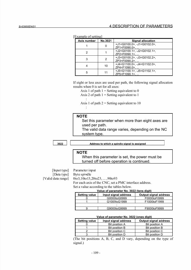
8/21/2019 30i Parameter Manual
http://slidepdf.com/reader/full/30i-parameter-manual 121/493
B-63950EN/01 4.DESCRIPTION OF PARAMETERS
- 109 -
[Example of setting]
Axis number No.3021 Signal allocation
1 0
+J1<G0100.0>, -J1<G0102.0>,
ZP1<F0090.0>, ...
2 1+J2<G0100.1>, -J2<G0102.1>,ZP2<F0090.1>, ...
3 2+J3<G0100.2>, -J3<G0102.2>,ZP3<F0090.2>, ...
4 10+J4<G1100.0>, -J4<G1102.0>,ZP4<F1090.0>, ...
5 11+J5<G1100.1>, -J5<G1102.1>,ZP5<F1090.1>, ...
If eight or less axes are used per path, the following signal allocation
results when 0 is set for all axes:
Axis 1 of path 1 = Setting equivalent to 0
Axis 2 of path 1 = Setting equivalent to 1:
Axis 1 of path 2 = Setting equivalent to 10
:
NOTESet this parameter when more than eight axes areused per path.The valid data range varies, depending on the NCsystem type.
3022 Address to which a spindle signal is assigned
NOTEWhen this parameter is set, the power must beturned off before operation is continued.
[Input type] Parameter input
[Data type] Byte spindle
[Valid data range] 0to3,10to13,20to23, ... ,90to93
For each axis of the CNC, set a PMC interface address.
Set a value according to the tables below.Value of parameter No. 3022 (tens digit)
Setting value Input signal address Output signal address
0 G0000toG0999 F0000toF09991 G1000toG1999 F1000toF1999
:9 G9000toG9999 F9000toF9999
Value of parameter No. 3022 (ones digit)
Setting value Input signal address Output signal address
0 Bit position A Bit position A1 Bit position B Bit position B2 Bit position C Bit position C3 Bit position D Bit position D
(The bit positions A, B, C, and D vary, depending on the type of
signal.)
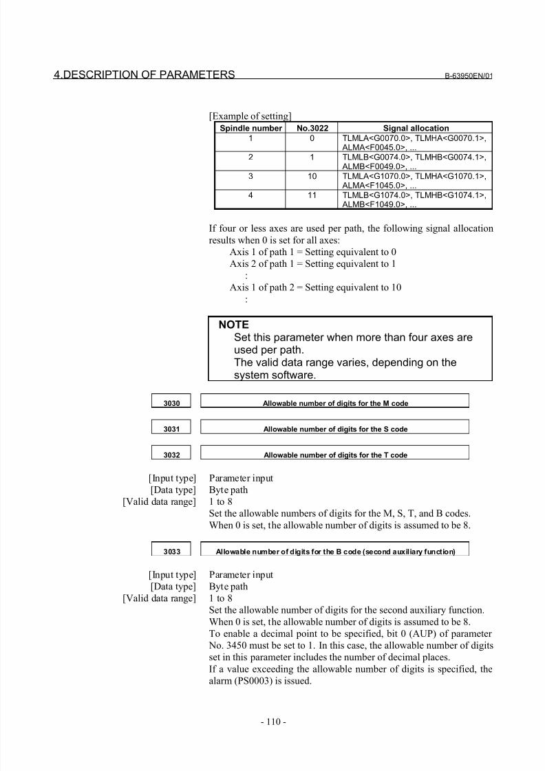
8/21/2019 30i Parameter Manual
http://slidepdf.com/reader/full/30i-parameter-manual 122/493
4.DESCRIPTION OF PARAMETERS B-63950EN/01
- 110 -
[Example of setting]
Spindle number No.3022 Signal allocation
1 0 TLMLA<G0070.0>, TLMHA<G0070.1>, ALMA<F0045.0>, ...
2 1 TLMLB<G0074.0>, TLMHB<G0074.1>, ALMB<F0049.0>, ...
3 10 TLMLA<G1070.0>, TLMHA<G1070.1>, ALMA<F1045.0>, ...
4 11 TLMLB<G1074.0>, TLMHB<G1074.1>, ALMB<F1049.0>, ...
If four or less axes are used per path, the following signal allocation
results when 0 is set for all axes:
Axis 1 of path 1 = Setting equivalent to 0
Axis 2 of path 1 = Setting equivalent to 1
:
Axis 1 of path 2 = Setting equivalent to 10
:
NOTESet this parameter when more than four axes areused per path.The valid data range varies, depending on thesystem software.
3030 Allowable number of digits for the M code
3031 Allowable number of digits for the S code
3032 Allowable number of digits for the T code
[Input type] Parameter input
[Data type] Byte path
[Valid data range] 1 to 8
Set the allowable numbers of digits for the M, S, T, and B codes.
When 0 is set, the allowable number of digits is assumed to be 8.
3033 Allowable number of digits for the B code (second auxiliary function)
[Input type] Parameter input
[Data type] Byte path
[Valid data range] 1 to 8
Set the allowable number of digits for the second auxiliary function.
When 0 is set, the allowable number of digits is assumed to be 8.
To enable a decimal point to be specified, bit 0 (AUP) of parameter
No. 3450 must be set to 1. In this case, the allowable number of digits
set in this parameter includes the number of decimal places.
If a value exceeding the allowable number of digits is specified, the
alarm (PS0003) is issued.
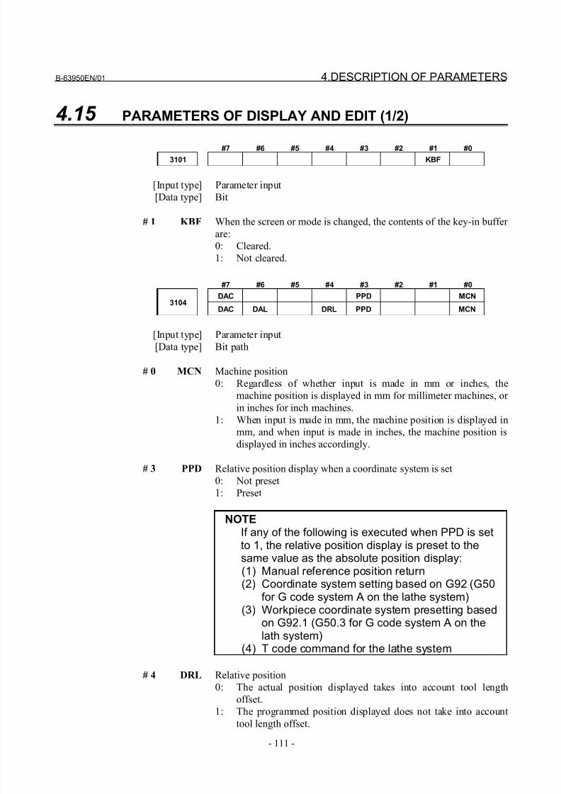
8/21/2019 30i Parameter Manual
http://slidepdf.com/reader/full/30i-parameter-manual 123/493
B-63950EN/01 4.DESCRIPTION OF PARAMETERS
- 111 -
4.15 PARAMETERS OF DISPLAY AND EDIT (1/2)
#7 #6 #5 #4 #3 #2 #1 #0
3101 KBF
[Input type] Parameter input
[Data type] Bit
# 1 KBF When the screen or mode is changed, the contents of the key-in buffer
are:
0: Cleared.
1: Not cleared.
#7 #6 #5 #4 #3 #2 #1 #0
DAC PPD MCN3104
DAC DAL DRL PPD MCN
[Input type] Parameter input
[Data type] Bit path
# 0 MCN Machine position
0: Regardless of whether input is made in mm or inches, the
machine position is displayed in mm for millimeter machines, or
in inches for inch machines.
1: When input is made in mm, the machine position is displayed inmm, and when input is made in inches, the machine position is
displayed in inches accordingly.
# 3 PPD Relative position display when a coordinate system is set
0: Not preset
1: Preset
NOTEIf any of the following is executed when PPD is setto 1, the relative position display is preset to the
same value as the absolute position display:(1) Manual reference position return(2) Coordinate system setting based on G92 (G50
for G code system A on the lathe system)(3) Workpiece coordinate system presetting based
on G92.1 (G50.3 for G code system A on thelath system)
(4) T code command for the lathe system
# 4 DRL Relative position
0: The actual position displayed takes into account tool length
offset.1: The programmed position displayed does not take into account
tool length offset.
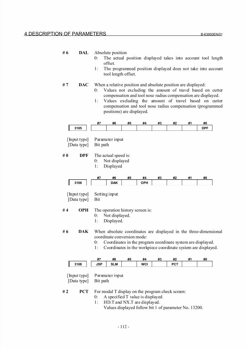
8/21/2019 30i Parameter Manual
http://slidepdf.com/reader/full/30i-parameter-manual 124/493
4.DESCRIPTION OF PARAMETERS B-63950EN/01
- 112 -
# 6 DAL Absolute position
0: The actual position displayed takes into account tool length
offset.
1: The programmed position displayed does not take into account
tool length offset.
# 7 DAC When a relative position and absolute position are displayed:
0: Values not excluding the amount of travel based on cutter
compensation and tool nose radius compensation are displayed.
1: Values excluding the amount of travel based on cutter
compensation and tool nose radius compensation (programmed
positions) are displayed.
#7 #6 #5 #4 #3 #2 #1 #0
3105 DPF
[Input type] Parameter input
[Data type] Bit path
# 0 DPF The actual speed is:
0: Not displayed
1: Displayed
#7 #6 #5 #4 #3 #2 #1 #0
3106 DAK OPH
[Input type] Setting input
[Data type] Bit
# 4 OPH The operation history screen is:
0: Not displayed.
1: Displayed.
# 6 DAK When absolute coordinates are displayed in the three-dimensional
coordinate conversion mode:
0: Coordinates in the program coordinate system are displayed.
1: Coordinates in the workpiece coordinate system are displayed.
#7 #6 #5 #4 #3 #2 #1 #0
3108 JSP SLM WCI PCT
[Input type] Parameter input
[Data type] Bit path
# 2 PCT For modal T display on the program check screen:
0: A specified T value is displayed.
1: HD.T and NX.T are displayed.
Values displayed follow bit 1 of parameter No. 13200.
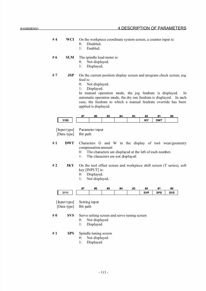
8/21/2019 30i Parameter Manual
http://slidepdf.com/reader/full/30i-parameter-manual 125/493
B-63950EN/01 4.DESCRIPTION OF PARAMETERS
- 113 -
# 4 WCI On the workpiece coordinate system screen, a counter input is:
0: Disabled.
1: Enabled.
# 6 SLM The spindle load meter is:
0: Not displayed.
1: Displayed.
# 7 JSP On the current position display screen and program check screen, jog
feed is:
0: Not displayed.
1: Displayed.
In manual operation mode, the jog feedrate is displayed. In
automatic operation mode, the dry run feedrate is displayed. In each
case, the feedrate to which a manual feedrate override has beenapplied is displayed.
#7 #6 #5 #4 #3 #2 #1 #0
3109 IKY DWT
[Input type] Parameter input
[Data type] Bit path
# 1 DWT Characters G and W in the display of tool wear/geometry
compensation amount
0: The characters are displayed at the left of each number.1: The characters are not displayed.
# 2 IKY On the tool offset screen and workpiece shift screen (T series), soft
key [INPUT] is:
0: Displayed.
1: Not displayed.
#7 #6 #5 #4 #3 #2 #1 #0
3111 SVP SPS SVS
[Input type] Setting input
[Data type] Bit path
# 0 SVS Servo setting screen and servo tuning screen
0: Not displayed
1: Displayed
# 1 SPS Spindle tuning screen
0: Not displayed
1: Displayed
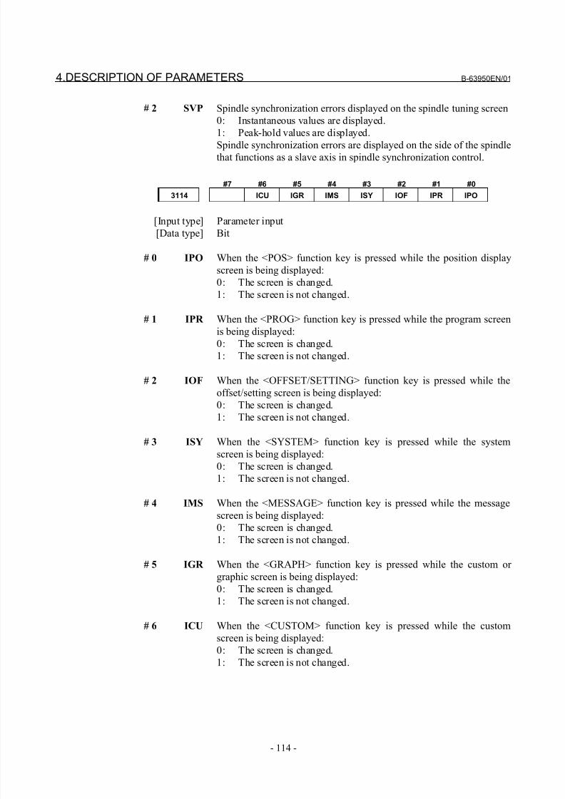
8/21/2019 30i Parameter Manual
http://slidepdf.com/reader/full/30i-parameter-manual 126/493
4.DESCRIPTION OF PARAMETERS B-63950EN/01
- 114 -
# 2 SVP Spindle synchronization errors displayed on the spindle tuning screen
0: Instantaneous values are displayed.
1: Peak-hold values are displayed.
Spindle synchronization errors are displayed on the side of the spindle
that functions as a slave axis in spindle synchronization control.
#7 #6 #5 #4 #3 #2 #1 #0
3114 ICU IGR IMS ISY IOF IPR IPO
[Input type] Parameter input
[Data type] Bit
# 0 IPO When the <POS> function key is pressed while the position display
screen is being displayed:
0: The screen is changed.1: The screen is not changed.
# 1 IPR When the <PROG> function key is pressed while the program screen
is being displayed:
0: The screen is changed.
1: The screen is not changed.
# 2 IOF When the <OFFSET/SETTING> function key is pressed while the
offset/setting screen is being displayed:
0: The screen is changed.
1: The screen is not changed.
# 3 ISY When the <SYSTEM> function key is pressed while the system
screen is being displayed:
0: The screen is changed.
1: The screen is not changed.
# 4 IMS When the <MESSAGE> function key is pressed while the message
screen is being displayed:
0: The screen is changed.
1: The screen is not changed.
# 5 IGR When the <GRAPH> function key is pressed while the custom or
graphic screen is being displayed:
0: The screen is changed.
1: The screen is not changed.
# 6 ICU When the <CUSTOM> function key is pressed while the custom
screen is being displayed:
0: The screen is changed.
1: The screen is not changed.
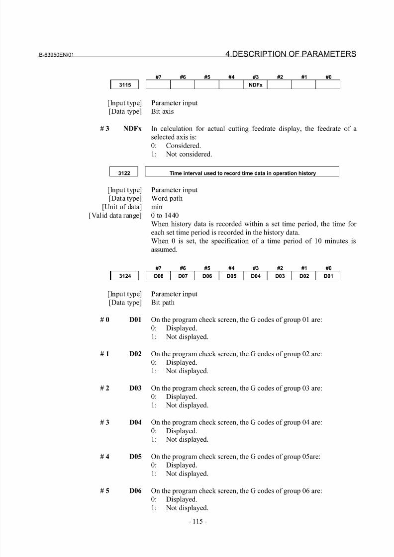
8/21/2019 30i Parameter Manual
http://slidepdf.com/reader/full/30i-parameter-manual 127/493
B-63950EN/01 4.DESCRIPTION OF PARAMETERS
- 115 -
#7 #6 #5 #4 #3 #2 #1 #0
3115 NDFx
[Input type] Parameter input
[Data type] Bit axis
# 3 NDFx In calculation for actual cutting feedrate display, the feedrate of a
selected axis is:
0: Considered.
1: Not considered.
3122 Time interval used to record time data in operation history
[Input type] Parameter input
[Data type] Word path
[Unit of data] min
[Valid data range] 0 to 1440
When history data is recorded within a set time period, the time for
each set time period is recorded in the history data.
When 0 is set, the specification of a time period of 10 minutes is
assumed.
#7 #6 #5 #4 #3 #2 #1 #0
3124 D08 D07 D06 D05 D04 D03 D02 D01
[Input type] Parameter input[Data type] Bit path
# 0 D01 On the program check screen, the G codes of group 01 are:
0: Displayed.
1: Not displayed.
# 1 D02 On the program check screen, the G codes of group 02 are:
0: Displayed.
1: Not displayed.
# 2 D03 On the program check screen, the G codes of group 03 are:0: Displayed.
1: Not displayed.
# 3 D04 On the program check screen, the G codes of group 04 are:
0: Displayed.
1: Not displayed.
# 4 D05 On the program check screen, the G codes of group 05are:
0: Displayed.
1: Not displayed.
# 5 D06 On the program check screen, the G codes of group 06 are:
0: Displayed.
1: Not displayed.
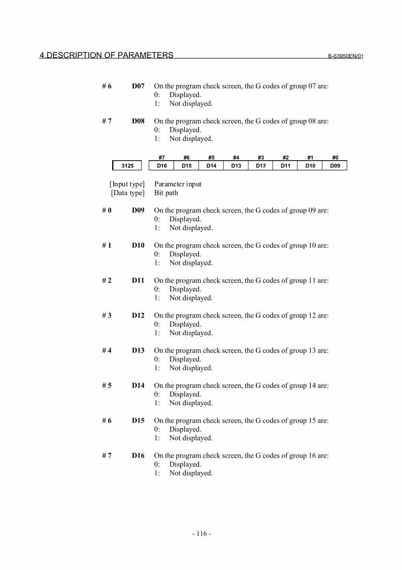
8/21/2019 30i Parameter Manual
http://slidepdf.com/reader/full/30i-parameter-manual 128/493
4.DESCRIPTION OF PARAMETERS B-63950EN/01
- 116 -
# 6 D07 On the program check screen, the G codes of group 07 are:
0: Displayed.
1: Not displayed.
# 7 D08 On the program check screen, the G codes of group 08 are:
0: Displayed.
1: Not displayed.
#7 #6 #5 #4 #3 #2 #1 #0
3125 D16 D15 D14 D13 D12 D11 D10 D09
[Input type] Parameter input
[Data type] Bit path
# 0 D09 On the program check screen, the G codes of group 09 are:
0: Displayed.
1: Not displayed.
# 1 D10 On the program check screen, the G codes of group 10 are:
0: Displayed.
1: Not displayed.
# 2 D11 On the program check screen, the G codes of group 11 are:
0: Displayed.
1: Not displayed.
# 3 D12 On the program check screen, the G codes of group 12 are:
0: Displayed.
1: Not displayed.
# 4 D13 On the program check screen, the G codes of group 13 are:
0: Displayed.
1: Not displayed.
# 5 D14 On the program check screen, the G codes of group 14 are:
0: Displayed.
1: Not displayed.
# 6 D15 On the program check screen, the G codes of group 15 are:
0: Displayed.
1: Not displayed.
# 7 D16 On the program check screen, the G codes of group 16 are:
0: Displayed.
1: Not displayed.
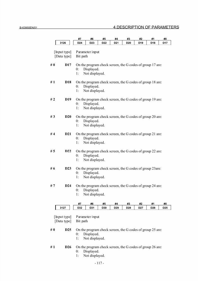
8/21/2019 30i Parameter Manual
http://slidepdf.com/reader/full/30i-parameter-manual 129/493
B-63950EN/01 4.DESCRIPTION OF PARAMETERS
- 117 -
#7 #6 #5 #4 #3 #2 #1 #0
3126 D24 D23 D22 D21 D20 D19 D18 D17
[Input type] Parameter input
[Data type] Bit path
# 0 D17 On the program check screen, the G codes of group 17 are:
0: Displayed.
1: Not displayed.
# 1 D18 On the program check screen, the G codes of group 18 are:
0: Displayed.
1: Not displayed.
# 2 D19 On the program check screen, the G codes of group 19 are:0: Displayed.
1: Not displayed.
# 3 D20 On the program check screen, the G codes of group 20 are:
0: Displayed.
1: Not displayed.
# 4 D21 On the program check screen, the G codes of group 21 are:
0: Displayed.
1: Not displayed.
# 5 D22 On the program check screen, the G codes of group 22 are:
0: Displayed.
1: Not displayed.
# 6 D23 On the program check screen, the G codes of group 23are:
0: Displayed.
1: Not displayed.
# 7 D24 On the program check screen, the G codes of group 24 are:
0: Displayed.
1: Not displayed.
#7 #6 #5 #4 #3 #2 #1 #0
3127 D32 D31 D30 D29 D28 D27 D26 D25
[Input type] Parameter input
[Data type] Bit path
# 0 D25 On the program check screen, the G codes of group 25 are:
0: Displayed.
1: Not displayed.
# 1 D26 On the program check screen, the G codes of group 26 are:0: Displayed.
1: Not displayed.
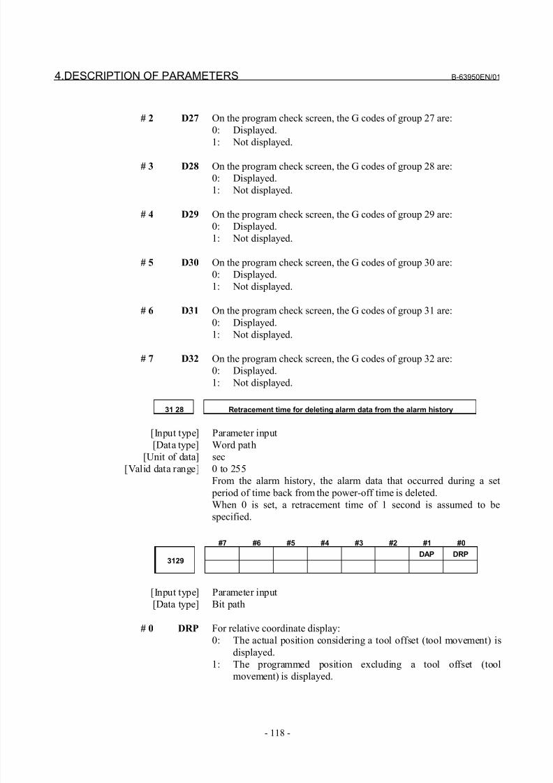
8/21/2019 30i Parameter Manual
http://slidepdf.com/reader/full/30i-parameter-manual 130/493
4.DESCRIPTION OF PARAMETERS B-63950EN/01
- 118 -
# 2 D27 On the program check screen, the G codes of group 27 are:
0: Displayed.
1: Not displayed.
# 3 D28 On the program check screen, the G codes of group 28 are:
0: Displayed.
1: Not displayed.
# 4 D29 On the program check screen, the G codes of group 29 are:
0: Displayed.
1: Not displayed.
# 5 D30 On the program check screen, the G codes of group 30 are:
0: Displayed.1: Not displayed.
# 6 D31 On the program check screen, the G codes of group 31 are:
0: Displayed.
1: Not displayed.
# 7 D32 On the program check screen, the G codes of group 32 are:
0: Displayed.
1: Not displayed.
31 28 Retracement time for deleting alarm data from the alarm history
[Input type] Parameter input
[Data type] Word path
[Unit of data] sec
[Valid data range] 0 to 255
From the alarm history, the alarm data that occurred during a set
period of time back from the power-off time is deleted.
When 0 is set, a retracement time of 1 second is assumed to be
specified.
#7 #6 #5 #4 #3 #2 #1 #0
DAP DRP3129
[Input type] Parameter input
[Data type] Bit path
# 0 DRP For relative coordinate display:
0: The actual position considering a tool offset (tool movement) is
displayed.
1: The programmed position excluding a tool offset (tool
movement) is displayed.
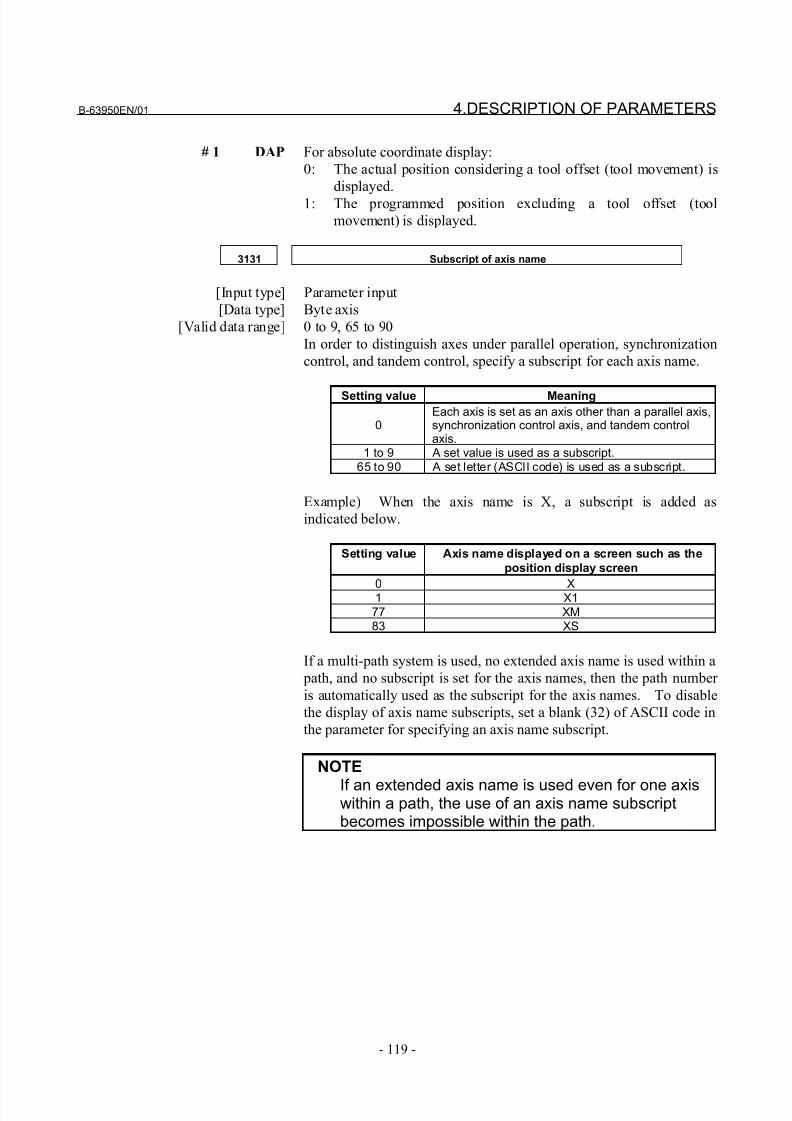
8/21/2019 30i Parameter Manual
http://slidepdf.com/reader/full/30i-parameter-manual 131/493
B-63950EN/01 4.DESCRIPTION OF PARAMETERS
- 119 -
# 1 DAP For absolute coordinate display:
0: The actual position considering a tool offset (tool movement) is
displayed.
1: The programmed position excluding a tool offset (tool
movement) is displayed.
3131 Subscript of axis name
[Input type] Parameter input
[Data type] Byte axis
[Valid data range] 0 to 9, 65 to 90
In order to distinguish axes under parallel operation, synchronization
control, and tandem control, specify a subscript for each axis name.
Setting value Meaning
0Each axis is set as an axis other than a parallel axis,synchronization control axis, and tandem controlaxis.
1 to 9 A set value is used as a subscript.65 to 90 A set letter (ASCII code) is used as a subscript.
Example) When the axis name is X, a subscript is added as
indicated below.
Setting value Axis name displayed on a screen such as the
position display screen
0 X1 X177 XM83 XS
If a multi-path system is used, no extended axis name is used within a
path, and no subscript is set for the axis names, then the path number
is automatically used as the subscript for the axis names. To disable
the display of axis name subscripts, set a blank (32) of ASCII code in
the parameter for specifying an axis name subscript.
NOTE
If an extended axis name is used even for one axiswithin a path, the use of an axis name subscriptbecomes impossible within the path.
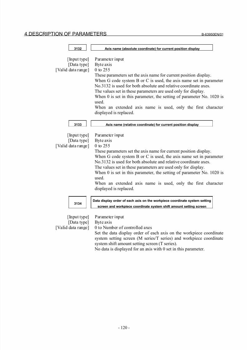
8/21/2019 30i Parameter Manual
http://slidepdf.com/reader/full/30i-parameter-manual 132/493
4.DESCRIPTION OF PARAMETERS B-63950EN/01
- 120 -
3132 Axis name (absolute coordinate) for current position display
[Input type] Parameter input[Data type] Byte axis
[Valid data range] 0 to 255
These parameters set the axis name for current position display.
When G code system B or C is used, the axis name set in parameter
No.3132 is used for both absolute and relative coordinate axes.
The values set in these parameters are used only for display.
When 0 is set in this parameter, the setting of parameter No. 1020 is
used.
When an extended axis name is used, only the first character
displayed is replaced.
3133 Axis name (relative coordinate) for current position display
[Input type] Parameter input
[Data type] Byte axis
[Valid data range] 0 to 255
These parameters set the axis name for current position display.
When G code system B or C is used, the axis name set in parameter
No.3132 is used for both absolute and relative coordinate axes.
The values set in these parameters are used only for display.
When 0 is set in this parameter, the setting of parameter No. 1020 is
used.
When an extended axis name is used, only the first character displayed is replaced.
3134Data display order of each axis on the workpiece coordinate system setting
screen and workpiece coordinate system shift amount setting screen
[Input type] Parameter input
[Data type] Byte axis
[Valid data range] 0 to Number of controlled axes
Set the data display order of each axis on the workpiece coordinate
system setting screen (M series/T series) and workpiece coordinate
system shift amount setting screen (T series). No data is displayed for an axis with 0 set in this parameter.
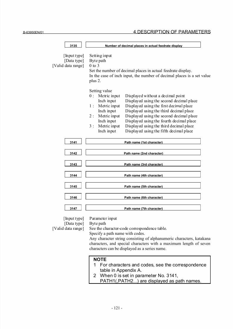
8/21/2019 30i Parameter Manual
http://slidepdf.com/reader/full/30i-parameter-manual 133/493
B-63950EN/01 4.DESCRIPTION OF PARAMETERS
- 121 -
3135 Number of decimal places in actual feedrate display
[Input type] Setting input[Data type] Byte path
[Valid data range] 0 to 3
Set the number of decimal places in actual feedrate display.
In the case of inch input, the number of decimal places is a set value
plus 2.
Setting value
0 : Metric input Displayed without a decimal point
Inch input Displayed using the second decimal place
1 : Metric input Displayed using the first decimal place
Inch input Displayed using the third decimal place
2 : Metric input Displayed using the second decimal placeInch input Displayed using the fourth decimal place
3 : Metric input Displayed using the third decimal place
Inch input Displayed using the fifth decimal place
3141 Path name (1st character)
3142 Path name (2nd character)
3143 Path name (3rd character)
3144 Path name (4th character)
3145 Path name (5th character)
3146 Path name (6th character)
3147 Path name (7th character)
[Input type] Parameter input
[Data type] Byte path
[Valid data range] See the character-code correspondence table.Specify a path name with codes.
Any character string consisting of alphanumeric characters, katakana
characters, and special characters with a maximum length of seven
characters can be displayed as a series name.
NOTE1 For characters and codes, see the correspondence
table in Appendix A.2 When 0 is set in parameter No. 3141,
PATH1(,PATH2...) are displayed as path names.
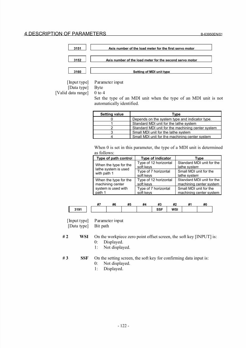
8/21/2019 30i Parameter Manual
http://slidepdf.com/reader/full/30i-parameter-manual 134/493
4.DESCRIPTION OF PARAMETERS B-63950EN/01
- 122 -
3151 Axis number of the load meter for the first servo motor
3152 Axis number of the load meter for the second servo motor
3160 Setting of MDI unit type
[Input type] Parameter input
[Data type] Byte
[Valid data range] 0 to 4
Set the type of an MDI unit when the type of an MDI unit is not
automatically identified.
Setting value Type
0 Depends on the system type and indicator type.1 Standard MDI unit for the lathe system2 Standard MDI unit for the machining center system3 Small MDI unit for the lathe system4 Small MDI unit for the machining center system
When 0 is set in this parameter, the type of a MDI unit is determined
as follows:
Type of path control Type of indicator Type
Type of 12 horizontalsoft keys
Standard MDI unit for thelathe system
When the type for thelathe system is usedwith path 1
Type of 7 horizontalsoft keys
Small MDI unit for thelathe system
Type of 12 horizontal
soft keys
Standard MDI unit for the
machining center system
When the type for the
machining center system is used withpath 1
Type of 7 horizontalsoft keys
Small MDI unit for themachining center system
#7 #6 #5 #4 #3 #2 #1 #0
3191 SSF WSI
[Input type] Parameter input
[Data type] Bit path
# 2 WSI On the workpiece zero point offset screen, the soft key [INPUT] is:
0: Displayed.1: Not displayed.
# 3 SSF On the setting screen, the soft key for confirming data input is:
0: Not displayed.
1: Displayed.
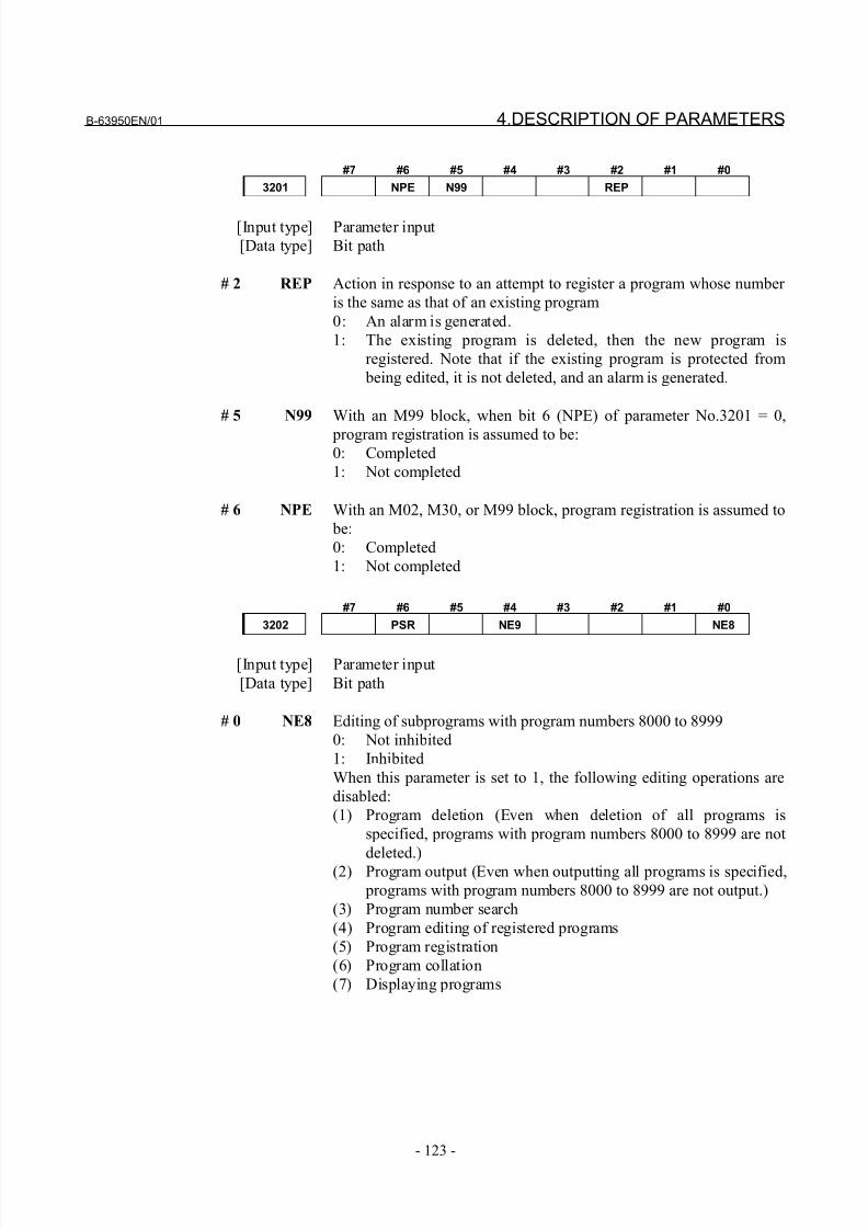
8/21/2019 30i Parameter Manual
http://slidepdf.com/reader/full/30i-parameter-manual 135/493
B-63950EN/01 4.DESCRIPTION OF PARAMETERS
- 123 -
#7 #6 #5 #4 #3 #2 #1 #0
3201 NPE N99 REP
[Input type] Parameter input
[Data type] Bit path
# 2 REP Action in response to an attempt to register a program whose number
is the same as that of an existing program
0: An alarm is generated.
1: The existing program is deleted, then the new program is
registered. Note that if the existing program is protected from
being edited, it is not deleted, and an alarm is generated.
# 5 N99 With an M99 block, when bit 6 (NPE) of parameter No.3201 = 0,
program registration is assumed to be:0: Completed
1: Not completed
# 6 NPE With an M02, M30, or M99 block, program registration is assumed to
be:
0: Completed
1: Not completed
#7 #6 #5 #4 #3 #2 #1 #0
3202 PSR NE9 NE8
[Input type] Parameter input
[Data type] Bit path
# 0 NE8 Editing of subprograms with program numbers 8000 to 8999
0: Not inhibited
1: Inhibited
When this parameter is set to 1, the following editing operations are
disabled:
(1) Program deletion (Even when deletion of all programs is
specified, programs with program numbers 8000 to 8999 are not
deleted.)
(2) Program output (Even when outputting all programs is specified,
programs with program numbers 8000 to 8999 are not output.)
(3) Program number search
(4) Program editing of registered programs
(5) Program registration
(6) Program collation
(7) Displaying programs
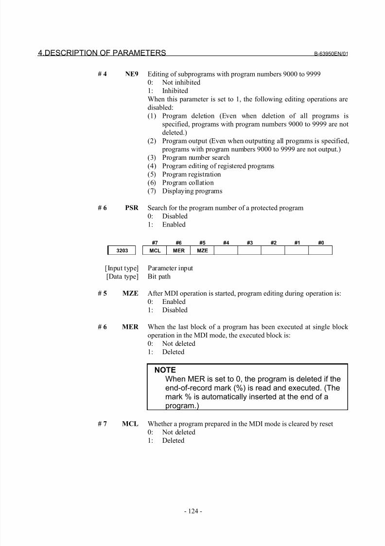
8/21/2019 30i Parameter Manual
http://slidepdf.com/reader/full/30i-parameter-manual 136/493
4.DESCRIPTION OF PARAMETERS B-63950EN/01
- 124 -
# 4 NE9 Editing of subprograms with program numbers 9000 to 9999
0: Not inhibited
1: Inhibited
When this parameter is set to 1, the following editing operations are
disabled:
(1) Program deletion (Even when deletion of all programs is
specified, programs with program numbers 9000 to 9999 are not
deleted.)
(2) Program output (Even when outputting all programs is specified,
programs with program numbers 9000 to 9999 are not output.)
(3) Program number search
(4) Program editing of registered programs
(5) Program registration
(6) Program collation
(7) Displaying programs
# 6 PSR Search for the program number of a protected program
0: Disabled
1: Enabled
#7 #6 #5 #4 #3 #2 #1 #0
3203 MCL MER MZE
[Input type] Parameter input
[Data type] Bit path
# 5 MZE After MDI operation is started, program editing during operation is:
0: Enabled
1: Disabled
# 6 MER When the last block of a program has been executed at single block
operation in the MDI mode, the executed block is:
0: Not deleted
1: Deleted
NOTE
When MER is set to 0, the program is deleted if theend-of-record mark (%) is read and executed. (Themark % is automatically inserted at the end of aprogram.)
# 7 MCL Whether a program prepared in the MDI mode is cleared by reset
0: Not deleted
1: Deleted
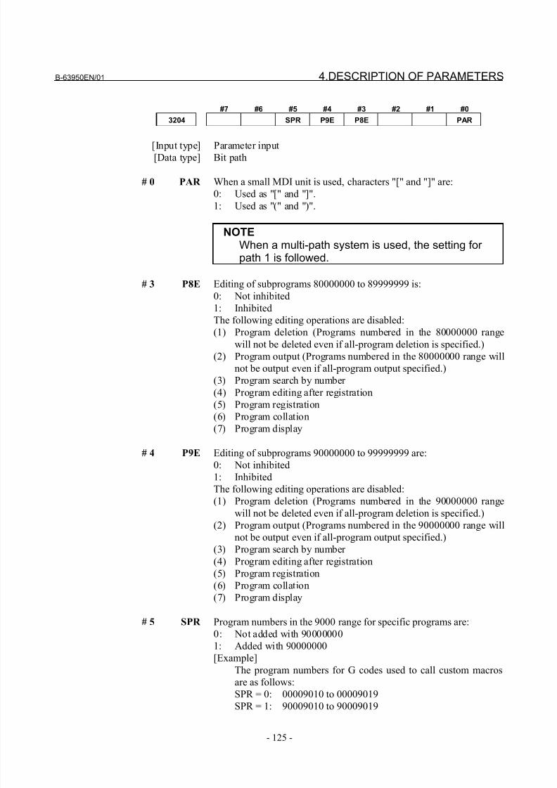
8/21/2019 30i Parameter Manual
http://slidepdf.com/reader/full/30i-parameter-manual 137/493
B-63950EN/01 4.DESCRIPTION OF PARAMETERS
- 125 -
#7 #6 #5 #4 #3 #2 #1 #0
3204 SPR P9E P8E PAR
[Input type] Parameter input
[Data type] Bit path
# 0 PAR When a small MDI unit is used, characters "[" and "]" are:
0: Used as "[" and "]".
1: Used as "(" and ")".
NOTEWhen a multi-path system is used, the setting for path 1 is followed.
# 3 P8E Editing of subprograms 80000000 to 89999999 is:
0: Not inhibited
1: Inhibited
The following editing operations are disabled:
(1) Program deletion (Programs numbered in the 80000000 range
will not be deleted even if all-program deletion is specified.)
(2) Program output (Programs numbered in the 80000000 range will
not be output even if all-program output specified.)
(3) Program search by number
(4) Program editing after registration
(5) Program registration
(6) Program collation(7) Program display
# 4 P9E Editing of subprograms 90000000 to 99999999 are:
0: Not inhibited
1: Inhibited
The following editing operations are disabled:
(1) Program deletion (Programs numbered in the 90000000 range
will not be deleted even if all-program deletion is specified.)
(2) Program output (Programs numbered in the 90000000 range will
not be output even if all-program output specified.)
(3) Program search by number (4) Program editing after registration
(5) Program registration
(6) Program collation
(7) Program display
# 5 SPR Program numbers in the 9000 range for specific programs are:
0: Not added with 90000000
1: Added with 90000000
[Example]
The program numbers for G codes used to call custom macros
are as follows:
SPR = 0: 00009010 to 00009019SPR = 1: 90009010 to 90009019
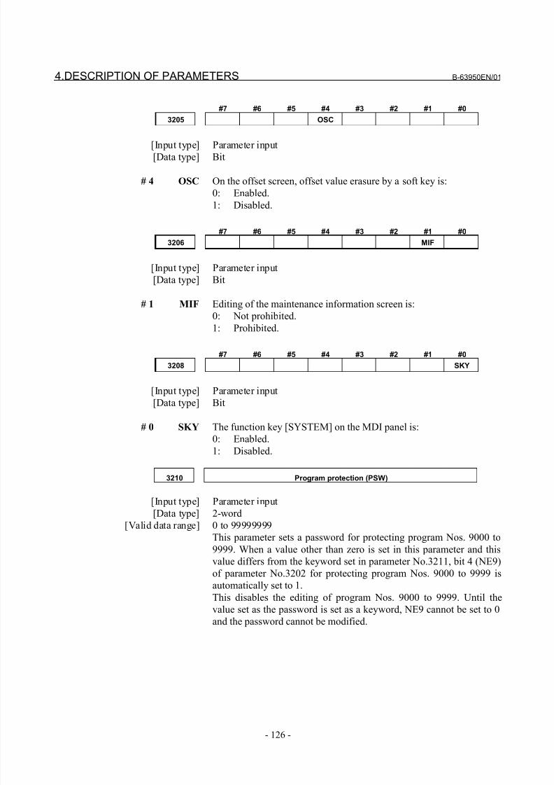
8/21/2019 30i Parameter Manual
http://slidepdf.com/reader/full/30i-parameter-manual 138/493
4.DESCRIPTION OF PARAMETERS B-63950EN/01
- 126 -
#7 #6 #5 #4 #3 #2 #1 #0
3205 OSC
[Input type] Parameter input
[Data type] Bit
# 4 OSC On the offset screen, offset value erasure by a soft key is:
0: Enabled.
1: Disabled.
#7 #6 #5 #4 #3 #2 #1 #0
3206 MIF
[Input type] Parameter input
[Data type] Bit
# 1 MIF Editing of the maintenance information screen is:
0: Not prohibited.
1: Prohibited.
#7 #6 #5 #4 #3 #2 #1 #0
3208 SKY
[Input type] Parameter input
[Data type] Bit
# 0 SKY The function key [SYSTEM] on the MDI panel is:
0: Enabled.
1: Disabled.
3210 Program protection (PSW)
[Input type] Parameter input
[Data type] 2-word
[Valid data range] 0 to 99999999
This parameter sets a password for protecting program Nos. 9000 to
9999. When a value other than zero is set in this parameter and thisvalue differs from the keyword set in parameter No.3211, bit 4 (NE9)
of parameter No.3202 for protecting program Nos. 9000 to 9999 is
automatically set to 1.
This disables the editing of program Nos. 9000 to 9999. Until the
value set as the password is set as a keyword, NE9 cannot be set to 0
and the password cannot be modified.
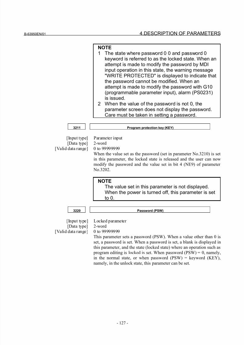
8/21/2019 30i Parameter Manual
http://slidepdf.com/reader/full/30i-parameter-manual 139/493
B-63950EN/01 4.DESCRIPTION OF PARAMETERS
- 127 -
NOTE1 The state where password 0 0 and password 0
keyword is referred to as the locked state. When anattempt is made to modify the password by MDIinput operation in this state, the warning message"WRITE PROTECTED" is displayed to indicate thatthe password cannot be modified. When anattempt is made to modify the password with G10(programmable parameter input), alarm (PS0231)is issued.
2 When the value of the password is not 0, theparameter screen does not display the password.Care must be taken in setting a password.
3211 Program protection key (KEY)
[Input type] Parameter input
[Data type] 2-word
[Valid data range] 0 to 99999999
When the value set as the password (set in parameter No.3210) is set
in this parameter, the locked state is released and the user can now
modify the password and the value set in bit 4 (NE9) of parameter
No.3202.
NOTEThe value set in this parameter is not displayed.When the power is turned off, this parameter is setto 0.
3220 Password (PSW)
[Input type] Locked parameter
[Data type] 2-word
[Valid data range] 0 to 99999999
This parameter sets a password (PSW). When a value other than 0 is
set, a password is set. When a password is set, a blank is displayed inthis parameter, and the state (locked state) where an operation such as
program editing is locked is set. When password (PSW) = 0, namely,
in the normal state, or when password (PSW) = keyword (KEY),
namely, in the unlock state, this parameter can be set.
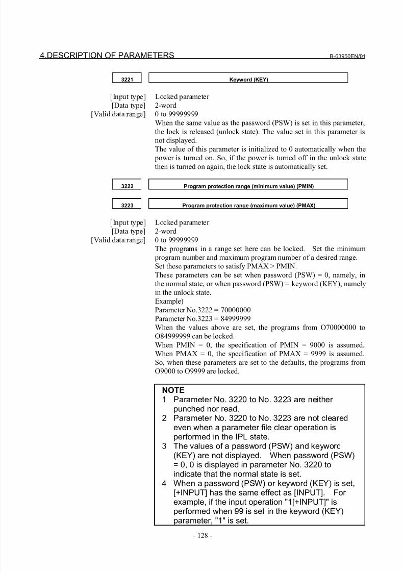
8/21/2019 30i Parameter Manual
http://slidepdf.com/reader/full/30i-parameter-manual 140/493
4.DESCRIPTION OF PARAMETERS B-63950EN/01
- 128 -
3221 Keyword (KEY)
[Input type] Locked parameter [Data type] 2-word
[Valid data range] 0 to 99999999
When the same value as the password (PSW) is set in this parameter,
the lock is released (unlock state). The value set in this parameter is
not displayed.
The value of this parameter is initialized to 0 automatically when the
power is turned on. So, if the power is turned off in the unlock state
then is turned on again, the lock state is automatically set.
3222 Program protection range (minimum value) (PMIN)
3223 Program protection range (maximum value) (PMAX)
[Input type] Locked parameter
[Data type] 2-word
[Valid data range] 0 to 99999999
The programs in a range set here can be locked. Set the minimum
program number and maximum program number of a desired range.
Set these parameters to satisfy PMAX > PMIN.
These parameters can be set when password (PSW) = 0, namely, in
the normal state, or when password (PSW) = keyword (KEY), namely
in the unlock state.
Example)Parameter No.3222 = 70000000
Parameter No.3223 = 84999999
When the values above are set, the programs from O70000000 to
O84999999 can be locked.
When PMIN = 0, the specification of PMIN = 9000 is assumed.
When PMAX = 0, the specification of PMAX = 9999 is assumed.
So, when these parameters are set to the defaults, the programs from
O9000 to O9999 are locked.
NOTE
1 Parameter No. 3220 to No. 3223 are neither punched nor read.
2 Parameter No. 3220 to No. 3223 are not clearedeven when a parameter file clear operation isperformed in the IPL state.
3 The values of a password (PSW) and keyword(KEY) are not displayed. When password (PSW)= 0, 0 is displayed in parameter No. 3220 toindicate that the normal state is set.
4 When a password (PSW) or keyword (KEY) is set,[+INPUT] has the same effect as [INPUT]. For
example, if the input operation "1[+INPUT]" isperformed when 99 is set in the keyword (KEY)parameter, "1" is set.
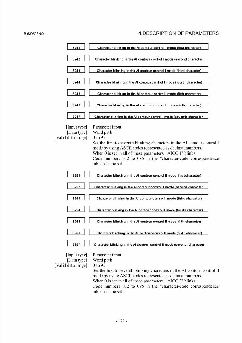
8/21/2019 30i Parameter Manual
http://slidepdf.com/reader/full/30i-parameter-manual 141/493
B-63950EN/01 4.DESCRIPTION OF PARAMETERS
- 129 -
3241 Character blinking in the AI contour control I mode (first character)
3242 Character blinking in the AI contour control I mode (second character)
3243 Character blinking in the AI contour control I mode (third character)
3244 Character blinking in the AI contour control I mode (fourth character)
3245 Character blinking in the AI contour control I mode (fifth character)
3246 Character blinking in the AI contour control I mode (sixth character)
3247 Character blinking in the AI contour control I mode (seventh character)
[Input type] Parameter input
[Data type] Word path
[Valid data range] 0 to 95
Set the first to seventh blinking characters in the AI contour control I
mode by using ASCII codes represented as decimal numbers.
When 0 is set in all of these parameters, "AICC 1" blinks.
Code numbers 032 to 095 in the "character-code correspondence
table" can be set.
3251 Character blinking in the AI contour control II mode (first character)
3252 Character blinking in the AI contour control II mode (second character)
3253 Character blinking in the AI contour control II mode (third character)
3254 Character blinking in the AI contour control II mode (fourth character)
3255 Character blinking in the AI contour control II mode (fifth character)
3256 Character blinking in the AI contour control II mode (sixth character)
3257 Character blinking in the AI contour control II mode (seventh character)
[Input type] Parameter input
[Data type] Word path
[Valid data range] 0 to 95
Set the first to seventh blinking characters in the AI contour control II
mode by using ASCII codes represented as decimal numbers.
When 0 is set in all of these parameters, "AICC 2" blinks.
Code numbers 032 to 095 in the "character-code correspondence
table" can be set.
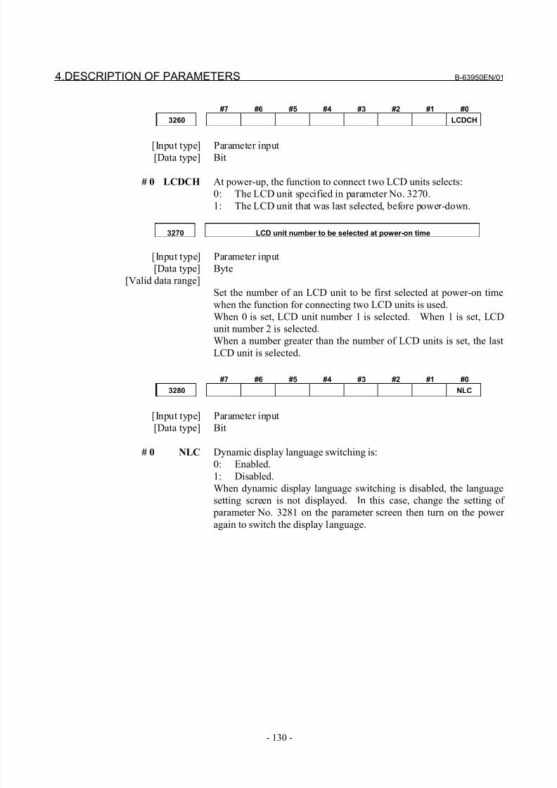
8/21/2019 30i Parameter Manual
http://slidepdf.com/reader/full/30i-parameter-manual 142/493
4.DESCRIPTION OF PARAMETERS B-63950EN/01
- 130 -
#7 #6 #5 #4 #3 #2 #1 #0
3260 LCDCH
[Input type] Parameter input
[Data type] Bit
# 0 LCDCH At power-up, the function to connect two LCD units selects:
0: The LCD unit specified in parameter No. 3270.
1: The LCD unit that was last selected, before power-down.
3270 LCD unit number to be selected at power-on time
[Input type] Parameter input
[Data type] Byte
[Valid data range]
Set the number of an LCD unit to be first selected at power-on time
when the function for connecting two LCD units is used.
When 0 is set, LCD unit number 1 is selected. When 1 is set, LCD
unit number 2 is selected.
When a number greater than the number of LCD units is set, the last
LCD unit is selected.
#7 #6 #5 #4 #3 #2 #1 #0
3280 NLC
[Input type] Parameter input[Data type] Bit
# 0 NLC Dynamic display language switching is:
0: Enabled.
1: Disabled.
When dynamic display language switching is disabled, the language
setting screen is not displayed. In this case, change the setting of
parameter No. 3281 on the parameter screen then turn on the power
again to switch the display language.
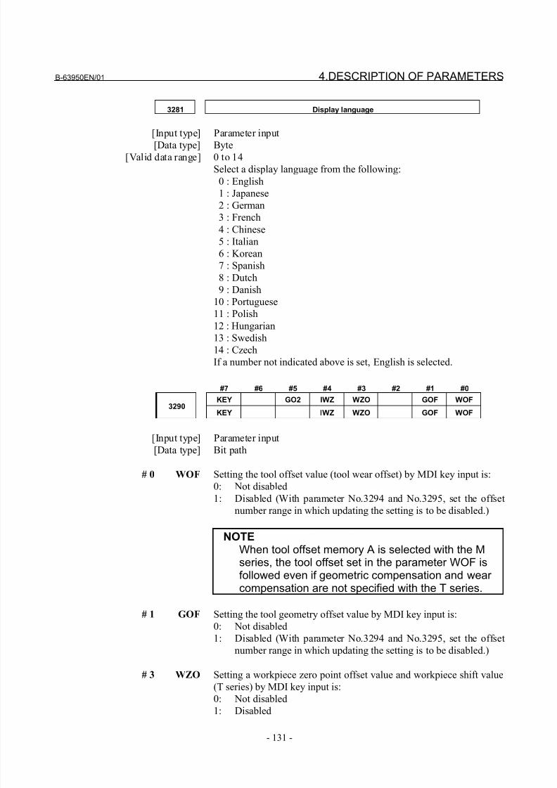
8/21/2019 30i Parameter Manual
http://slidepdf.com/reader/full/30i-parameter-manual 143/493
B-63950EN/01 4.DESCRIPTION OF PARAMETERS
- 131 -
3281 Display language
[Input type] Parameter input[Data type] Byte
[Valid data range] 0 to 14
Select a display language from the following:
0 : English
1 : Japanese
2 : German
3 : French
4 : Chinese
5 : Italian
6 : Korean
7 : Spanish
8 : Dutch 9 : Danish
10 : Portuguese
11 : Polish
12 : Hungarian
13 : Swedish
14 : Czech
If a number not indicated above is set, English is selected.
#7 #6 #5 #4 #3 #2 #1 #0
KEY GO2 IWZ WZO GOF WOF3290
KEY IWZ WZO GOF WOF
[Input type] Parameter input
[Data type] Bit path
# 0 WOF Setting the tool offset value (tool wear offset) by MDI key input is:
0: Not disabled
1: Disabled (With parameter No.3294 and No.3295, set the offset
number range in which updating the setting is to be disabled.)
NOTE
When tool offset memory A is selected with the Mseries, the tool offset set in the parameter WOF isfollowed even if geometric compensation and wear compensation are not specified with the T series.
# 1 GOF Setting the tool geometry offset value by MDI key input is:
0: Not disabled
1: Disabled (With parameter No.3294 and No.3295, set the offset
number range in which updating the setting is to be disabled.)
# 3 WZO Setting a workpiece zero point offset value and workpiece shift value
(T series) by MDI key input is:0: Not disabled
1: Disabled
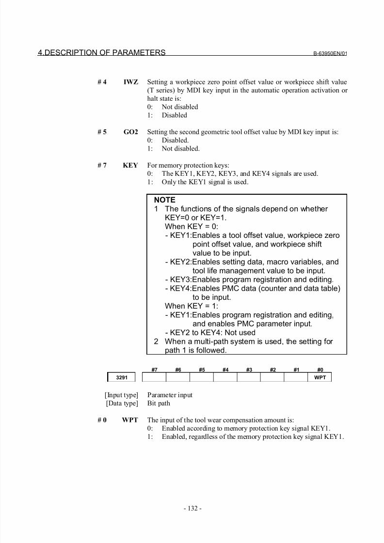
8/21/2019 30i Parameter Manual
http://slidepdf.com/reader/full/30i-parameter-manual 144/493
4.DESCRIPTION OF PARAMETERS B-63950EN/01
- 132 -
# 4 IWZ Setting a workpiece zero point offset value or workpiece shift value
(T series) by MDI key input in the automatic operation activation or
halt state is:
0: Not disabled
1: Disabled
# 5 GO2 Setting the second geometric tool offset value by MDI key input is:
0: Disabled.
1: Not disabled.
# 7 KEY For memory protection keys:
0: The KEY1, KEY2, KEY3, and KEY4 signals are used.
1: Only the KEY1 signal is used.
NOTE1 The functions of the signals depend on whether
KEY=0 or KEY=1.When KEY = 0:- KEY1:Enables a tool offset value, workpiece zero
point offset value, and workpiece shiftvalue to be input.
- KEY2:Enables setting data, macro variables, andtool life management value to be input.
- KEY3:Enables program registration and editing.- KEY4:Enables PMC data (counter and data table)
to be input.When KEY = 1:- KEY1:Enables program registration and editing,
and enables PMC parameter input.- KEY2 to KEY4: Not used
2 When a multi-path system is used, the setting for path 1 is followed.
#7 #6 #5 #4 #3 #2 #1 #0
3291 WPT
[Input type] Parameter input
[Data type] Bit path
# 0 WPT The input of the tool wear compensation amount is:
0: Enabled according to memory protection key signal KEY1.
1: Enabled, regardless of the memory protection key signal KEY1.
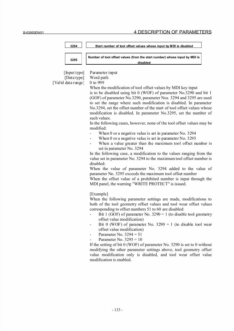
8/21/2019 30i Parameter Manual
http://slidepdf.com/reader/full/30i-parameter-manual 145/493
B-63950EN/01 4.DESCRIPTION OF PARAMETERS
- 133 -
3294 Start number of tool offset values whose input by MDI is disabled
3295 Number of tool offset values (from the start number) whose input by MDI isdisabled
[Input type] Parameter input
[Data type] Word path
[Valid data range] 0 to 999
When the modification of tool offset values by MDI key input
is to be disabled using bit 0 (WOF) of parameter No.3290 and bit 1
(GOF) of parameter No.3290, parameter Nos. 3294 and 3295 are used
to set the range where such modification is disabled. In parameter
No.3294, set the offset number of the start of tool offset values whose
modification is disabled. In parameter No.3295, set the number of
such values.
In the following cases, however, none of the tool offset values may be
modified:
- When 0 or a negative value is set in parameter No. 3294
- When 0 or a negative value is set in parameter No. 3295
- When a value greater than the maximum tool offset number is
set in parameter No. 3294
In the following case, a modification to the values ranging from the
value set in parameter No. 3294 to the maximum tool offset number is
disabled:
When the value of parameter No. 3294 added to the value of
parameter No. 3295 exceeds the maximum tool offset number When the offset value of a prohibited number is input through the
MDI panel, the warning "WRITE PROTECT" is issued.
[Example]
When the following parameter settings are made, modifications to
both of the tool geometry offset values and tool wear offset values
corresponding to offset numbers 51 to 60 are disabled:
- Bit 1 (GOF) of parameter No. 3290 = 1 (to disable tool geometry
offset value modification)
- Bit 0 (WOF) of parameter No. 3290 = 1 (to disable tool wear
offset value modification)
- Parameter No. 3294 = 51
- Parameter No. 3295 = 10
If the setting of bit 0 (WOF) of parameter No. 3290 is set to 0 without
modifying the other parameter settings above, tool geometry offset
value modification only is disabled, and tool wear offset value
modification is enabled.
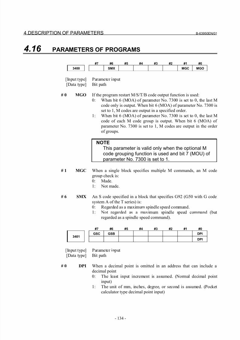
8/21/2019 30i Parameter Manual
http://slidepdf.com/reader/full/30i-parameter-manual 146/493
4.DESCRIPTION OF PARAMETERS B-63950EN/01
- 134 -
4.16 PARAMETERS OF PROGRAMS
#7 #6 #5 #4 #3 #2 #1 #0
3400 SMX MGC MGO
[Input type] Parameter input
[Data type] Bit path
# 0 MGO If the program restart M/S/T/B code output function is used:
0: When bit 6 (MOA) of parameter No. 7300 is set to 0, the last M
code only is output. When bit 6 (MOA) of parameter No. 7300 is
set to 1, M codes are output in a specified order.
1: When bit 6 (MOA) of parameter No. 7300 is set to 0, the last M
code of each M code group is output. When bit 6 (MOA) of
parameter No. 7300 is set to 1, M codes are output in the order
of groups.
NOTEThis parameter is valid only when the optional Mcode grouping function is used and bit 7 (MOU) of parameter No. 7300 is set to 1.
# 1 MGC When a single block specifies multiple M commands, an M code
group check is:
0: Made.
1: Not made.
# 6 SMX An S code specified in a block that specifies G92 (G50 with G code
system A of the T series) is:
0: Regarded as a maximum spindle speed command.
1: Not regarded as a maximum spindle speed command (but
regarded as a spindle speed command).
#7 #6 #5 #4 #3 #2 #1 #0
GSC GSB DPI
3401 DPI
[Input type] Parameter input
[Data type] Bit path
# 0 DPI When a decimal point is omitted in an address that can include a
decimal point
0: The least input increment is assumed. (Normal decimal point
input)
1: The unit of mm, inches, degree, or second is assumed. (Pocket
calculator type decimal point input)
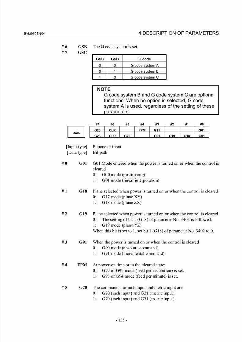
8/21/2019 30i Parameter Manual
http://slidepdf.com/reader/full/30i-parameter-manual 147/493
B-63950EN/01 4.DESCRIPTION OF PARAMETERS
- 135 -
# 6 GSB The G code system is set.
# 7 GSC
GSC GSB G code0 0 G code system A
0 1 G code system B
1 0 G code system C
NOTEG code system B and G code system C are optionalfunctions. When no option is selected, G codesystem A is used, regardless of the setting of theseparameters.
#7 #6 #5 #4 #3 #2 #1 #0
G23 CLR FPM G91 G013402
G23 CLR G70 G91 G19 G18 G01
[Input type] Parameter input
[Data type] Bit path
# 0 G01 G01 Mode entered when the power is turned on or when the control is
cleared
0: G00 mode (positioning)
1: G01 mode (linear interpolation)
# 1 G18 Plane selected when power is turned on or when the control is cleared
0: G17 mode (plane XY)
1: G18 mode (plane ZX)
# 2 G19 Plane selected when power is turned on or when the control is cleared
0: The setting of bit 1 (G18) of parameter No. 3402 is followed.
1: G19 mode (plane YZ)
When this bit is set to 1, set bit 1 (G18) of parameter No. 3402 to 0.
# 3 G91 When the power is turned on or when the control is cleared
0: G90 mode (absolute command)
1: G91 mode (incremental command)
# 4 FPM At power-on time or in the cleared state:
0: G99 or G95 mode (feed per revolution) is set.
1: G98 or G94 mode (feed per minute) is set.
# 5 G70 The commands for inch input and metric input are:
0: G20 (inch input) and G21 (metric input).
1: G70 (inch input) and G71 (metric input).

8/21/2019 30i Parameter Manual
http://slidepdf.com/reader/full/30i-parameter-manual 148/493
4.DESCRIPTION OF PARAMETERS B-63950EN/01
- 136 -
# 6 CLR Reset button on the MDI panel, external reset signal, reset and rewind
signal, and emergency stop signal
0: Cause reset state.1: Cause clear state.
For the reset and clear states, refer to Appendix in the User's Manual.
# 7 G23 When the power is turned on
0: G22 mode (stored stroke check on)
1: G23 mode (stored stroke check off)
#7 #6 #5 #4 #3 #2 #1 #0
3403 CIR
[Input type] Parameter input[Data type] Bit path
# 5 CIR When neither the distance (I, J, K) from a start point to the center nor
an arc radius (R) is specified in circular interpolation (G02, G03) or
helical interpolation (G02, G03):
0: The tool moves to an end point by linear interpolation.
1: An alarm PS0022 is issued.
#7 #6 #5 #4 #3 #2 #1 #0
3404 M3B M02 M30
[Input type] Parameter input
[Data type] Bit path
# 4 M30 When M30 is specified in a memory operation:
0: M30 is sent to the machine, and the head of the program is
automatically searched for. So, when the ready signal FIN is
returned and a reset or reset and rewind operation is not
performed, the program is executed, starting from the beginning.
1: M30 is sent to the machine, but the head of the program is not
searched for. (The head of the program is searched for by the
reset and rewind signal.)
# 5 M02 When M02 is specified in memory operation
0: M02 is sent to the machine, and the head of the program is
automatically searched for. So, when the end signal FIN is
returned and a reset or reset and rewind operation is not
performed, the program is executed, starting from the beginning.
1: M02 is sent to the machine, but the head of the program is not
searched for. (The head of the program is searched for by the
reset and rewind signal.)
# 7 M3B The number of M codes that can be specified in one block
0: One
1: Up to three
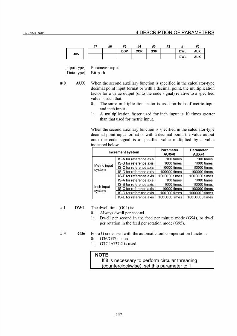
8/21/2019 30i Parameter Manual
http://slidepdf.com/reader/full/30i-parameter-manual 149/493
B-63950EN/01 4.DESCRIPTION OF PARAMETERS
- 137 -
#7 #6 #5 #4 #3 #2 #1 #0
DDP CCR G36 DWL AUX3405
DWL AUX
[Input type] Parameter input
[Data type] Bit path
# 0 AUX When the second auxiliary function is specified in the calculator-type
decimal point input format or with a decimal point, the multiplication
factor for a value output (onto the code signal) relative to a specified
value is such that:
0: The same multiplication factor is used for both of metric input
and inch input.
1: A multiplication factor used for inch input is 10 times greater
than that used for metric input.
When the second auxiliary function is specified in the calculator-type
decimal point input format or with a decimal point, the value output
onto the code signal is a specified value multiplied by a value
indicated below.
Increment systemParameter
AUX=0
Parameter
AUX=1
IS-A for reference axis 100 times 100 timesIS-B for reference axis 1000 times 1000 timesIS-C for reference axis 10000 times 10000 timesIS-D for reference axis 100000 times 100000 times
Metric inputsystem
IS-E for reference axis 1000000 times 1000000 timesIS-A for reference axis 100 times 1000 timesIS-B for reference axis 1000 times 10000 timesIS-C for reference axis 10000 times 100000 timesIS-D for reference axis 100000 times 1000000 times
Inch inputsystem
IS-E for reference axis 1000000 times 10000000 times
# 1 DWL The dwell time (G04) is:
0: Always dwell per second.
1: Dwell per second in the feed per minute mode (G94), or dwell
per rotation in the feed per rotation mode (G95).
# 3 G36 For a G code used with the automatic tool compensation function:0: G36/G37 is used.
1: G37.1/G37.2 is used.
NOTEIf it is necessary to perform circular threading(counterclockwise), set this parameter to 1.
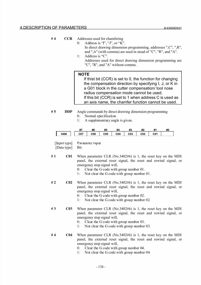
8/21/2019 30i Parameter Manual
http://slidepdf.com/reader/full/30i-parameter-manual 150/493
4.DESCRIPTION OF PARAMETERS B-63950EN/01
- 138 -
# 4 CCR Addresses used for chamfering
0: Address is “I”, “J”, or “K”.
In direct drawing dimension programming, addresses ",C", ",R",
and ",A" (with comma) are used in stead of "C", "R", and "A".
1: Address is “C”.
Addresses used for direct drawing dimension programming are
"C", "R", and "A" without comma.
NOTEIf thist bit (CCR) is set to 0, the function for changingthe compensation direction by specifying I, J, or K ina G01 block in the cutter compensation/ tool noseradius compensation mode cannot be used.If this bit (CCR) is set to 1 when address C is used asan axis name, the chamfer function cannot be used.
# 5 DDP Angle commands by direct drawing dimension programming
0: Normal specification
1: A supplementary angle is given.
#7 #6 #5 #4 #3 #2 #1 #0
3406 C07 C06 C05 C04 C03 C02 C01
[Input type] Parameter input
[Data type] Bit
# 1 C01 When parameter CLR (No.3402#6) is 1, the reset key on the MDI
panel, the external reset signal, the reset and rewind signal, or
emergency stop signal will,
0: Clear the G code with group number 01.
1: Not clear the G code with group number 01.
# 2 C02 When parameter CLR (No.3402#6) is 1, the reset key on the MDI
panel, the external reset signal, the reset and rewind signal, or
emergency stop signal will,
0: Clear the G code with group number 02.
1: Not clear the G code with group number 02.
# 3 C03 When parameter CLR (No.3402#6) is 1, the reset key on the MDI
panel, the external reset signal, the reset and rewind signal, or
emergency stop signal will,
0: Clear the G code with group number 03.
1: Not clear the G code with group number 03.
# 4 C04 When parameter CLR (No.3402#6) is 1, the reset key on the MDI
panel, the external reset signal, the reset and rewind signal, or
emergency stop signal will,
0: Clear the G code with group number 04.1: Not clear the G code with group number 04.
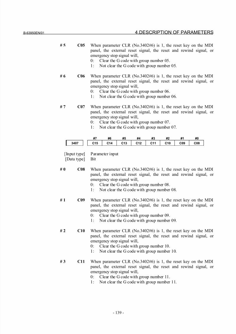
8/21/2019 30i Parameter Manual
http://slidepdf.com/reader/full/30i-parameter-manual 151/493
B-63950EN/01 4.DESCRIPTION OF PARAMETERS
- 139 -
# 5 C05 When parameter CLR (No.3402#6) is 1, the reset key on the MDI
panel, the external reset signal, the reset and rewind signal, or
emergency stop signal will,
0: Clear the G code with group number 05.
1: Not clear the G code with group number 05.
# 6 C06 When parameter CLR (No.3402#6) is 1, the reset key on the MDI
panel, the external reset signal, the reset and rewind signal, or
emergency stop signal will,
0: Clear the G code with group number 06.
1: Not clear the G code with group number 06.
# 7 C07 When parameter CLR (No.3402#6) is 1, the reset key on the MDI
panel, the external reset signal, the reset and rewind signal, or
emergency stop signal will,0: Clear the G code with group number 07.
1: Not clear the G code with group number 07.
#7 #6 #5 #4 #3 #2 #1 #0
3407 C15 C14 C13 C12 C11 C10 C09 C08
[Input type] Parameter input
[Data type] Bit
# 0 C08 When parameter CLR (No.3402#6) is 1, the reset key on the MDI
panel, the external reset signal, the reset and rewind signal, or emergency stop signal will,
0: Clear the G code with group number 08.
1: Not clear the G code with group number 08.
# 1 C09 When parameter CLR (No.3402#6) is 1, the reset key on the MDI
panel, the external reset signal, the reset and rewind signal, or
emergency stop signal will,
0: Clear the G code with group number 09.
1: Not clear the G code with group number 09.
# 2 C10 When parameter CLR (No.3402#6) is 1, the reset key on the MDI
panel, the external reset signal, the reset and rewind signal, or
emergency stop signal will,
0: Clear the G code with group number 10.
1: Not clear the G code with group number 10.
# 3 C11 When parameter CLR (No.3402#6) is 1, the reset key on the MDI
panel, the external reset signal, the reset and rewind signal, or
emergency stop signal will,
0: Clear the G code with group number 11.
1: Not clear the G code with group number 11.
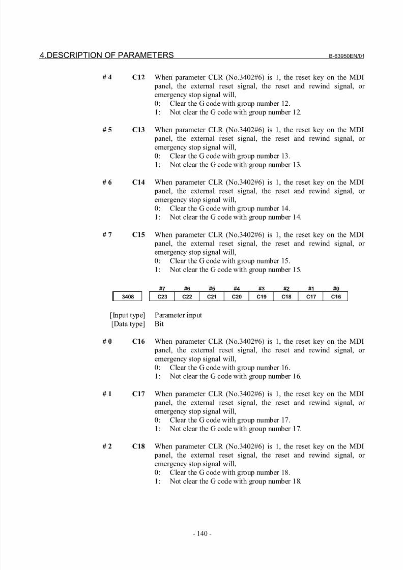
8/21/2019 30i Parameter Manual
http://slidepdf.com/reader/full/30i-parameter-manual 152/493
4.DESCRIPTION OF PARAMETERS B-63950EN/01
- 140 -
# 4 C12 When parameter CLR (No.3402#6) is 1, the reset key on the MDI
panel, the external reset signal, the reset and rewind signal, or
emergency stop signal will,
0: Clear the G code with group number 12.
1: Not clear the G code with group number 12.
# 5 C13 When parameter CLR (No.3402#6) is 1, the reset key on the MDI
panel, the external reset signal, the reset and rewind signal, or
emergency stop signal will,
0: Clear the G code with group number 13.
1: Not clear the G code with group number 13.
# 6 C14 When parameter CLR (No.3402#6) is 1, the reset key on the MDI
panel, the external reset signal, the reset and rewind signal, or
emergency stop signal will,0: Clear the G code with group number 14.
1: Not clear the G code with group number 14.
# 7 C15 When parameter CLR (No.3402#6) is 1, the reset key on the MDI
panel, the external reset signal, the reset and rewind signal, or
emergency stop signal will,
0: Clear the G code with group number 15.
1: Not clear the G code with group number 15.
#7 #6 #5 #4 #3 #2 #1 #0
3408 C23 C22 C21 C20 C19 C18 C17 C16
[Input type] Parameter input
[Data type] Bit
# 0 C16 When parameter CLR (No.3402#6) is 1, the reset key on the MDI
panel, the external reset signal, the reset and rewind signal, or
emergency stop signal will,
0: Clear the G code with group number 16.
1: Not clear the G code with group number 16.
# 1 C17 When parameter CLR (No.3402#6) is 1, the reset key on the MDI
panel, the external reset signal, the reset and rewind signal, or
emergency stop signal will,
0: Clear the G code with group number 17.
1: Not clear the G code with group number 17.
# 2 C18 When parameter CLR (No.3402#6) is 1, the reset key on the MDI
panel, the external reset signal, the reset and rewind signal, or
emergency stop signal will,
0: Clear the G code with group number 18.
1: Not clear the G code with group number 18.
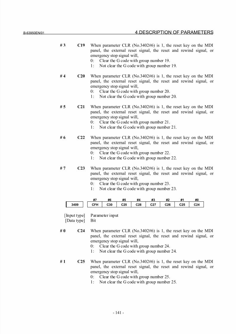
8/21/2019 30i Parameter Manual
http://slidepdf.com/reader/full/30i-parameter-manual 153/493
B-63950EN/01 4.DESCRIPTION OF PARAMETERS
- 141 -
# 3 C19 When parameter CLR (No.3402#6) is 1, the reset key on the MDI
panel, the external reset signal, the reset and rewind signal, or
emergency stop signal will,
0: Clear the G code with group number 19.
1: Not clear the G code with group number 19.
# 4 C20 When parameter CLR (No.3402#6) is 1, the reset key on the MDI
panel, the external reset signal, the reset and rewind signal, or
emergency stop signal will,
0: Clear the G code with group number 20.
1: Not clear the G code with group number 20.
# 5 C21 When parameter CLR (No.3402#6) is 1, the reset key on the MDI
panel, the external reset signal, the reset and rewind signal, or
emergency stop signal will,0: Clear the G code with group number 21.
1: Not clear the G code with group number 21.
# 6 C22 When parameter CLR (No.3402#6) is 1, the reset key on the MDI
panel, the external reset signal, the reset and rewind signal, or
emergency stop signal will,
0: Clear the G code with group number 22.
1: Not clear the G code with group number 22.
# 7 C23 When parameter CLR (No.3402#6) is 1, the reset key on the MDI
panel, the external reset signal, the reset and rewind signal, or emergency stop signal will,
0: Clear the G code with group number 23.
1: Not clear the G code with group number 23.
#7 #6 #5 #4 #3 #2 #1 #0
3409 CFH C30 C29 C28 C27 C26 C25 C24
[Input type] Parameter input
[Data type] Bit
# 0 C24 When parameter CLR (No.3402#6) is 1, the reset key on the MDI
panel, the external reset signal, the reset and rewind signal, or
emergency stop signal will,
0: Clear the G code with group number 24.
1: Not clear the G code with group number 24.
# 1 C25 When parameter CLR (No.3402#6) is 1, the reset key on the MDI
panel, the external reset signal, the reset and rewind signal, or
emergency stop signal will,
0: Clear the G code with group number 25.
1: Not clear the G code with group number 25.
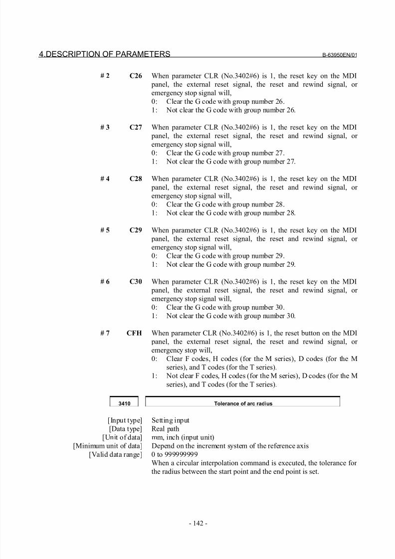
8/21/2019 30i Parameter Manual
http://slidepdf.com/reader/full/30i-parameter-manual 154/493
4.DESCRIPTION OF PARAMETERS B-63950EN/01
- 142 -
# 2 C26 When parameter CLR (No.3402#6) is 1, the reset key on the MDI
panel, the external reset signal, the reset and rewind signal, or
emergency stop signal will,
0: Clear the G code with group number 26.
1: Not clear the G code with group number 26.
# 3 C27 When parameter CLR (No.3402#6) is 1, the reset key on the MDI
panel, the external reset signal, the reset and rewind signal, or
emergency stop signal will,
0: Clear the G code with group number 27.
1: Not clear the G code with group number 27.
# 4 C28 When parameter CLR (No.3402#6) is 1, the reset key on the MDI
panel, the external reset signal, the reset and rewind signal, or
emergency stop signal will,0: Clear the G code with group number 28.
1: Not clear the G code with group number 28.
# 5 C29 When parameter CLR (No.3402#6) is 1, the reset key on the MDI
panel, the external reset signal, the reset and rewind signal, or
emergency stop signal will,
0: Clear the G code with group number 29.
1: Not clear the G code with group number 29.
# 6 C30 When parameter CLR (No.3402#6) is 1, the reset key on the MDI
panel, the external reset signal, the reset and rewind signal, or emergency stop signal will,
0: Clear the G code with group number 30.
1: Not clear the G code with group number 30.
# 7 CFH When parameter CLR (No.3402#6) is 1, the reset button on the MDI
panel, the external reset signal, the reset and rewind signal, or
emergency stop will,
0: Clear F codes, H codes (for the M series), D codes (for the M
series), and T codes (for the T series).
1: Not clear F codes, H codes (for the M series), D codes (for the M
series), and T codes (for the T series).
3410 Tolerance of arc radius
[Input type] Setting input
[Data type] Real path
[Unit of data] mm, inch (input unit)
[Minimum unit of data] Depend on the increment system of the reference axis
[Valid data range] 0 to 999999999
When a circular interpolation command is executed, the tolerance for
the radius between the start point and the end point is set.
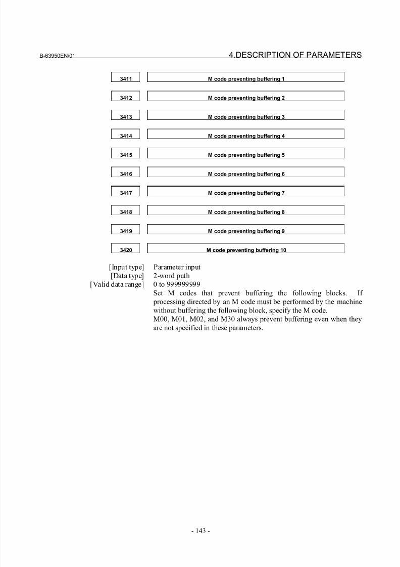
8/21/2019 30i Parameter Manual
http://slidepdf.com/reader/full/30i-parameter-manual 155/493
B-63950EN/01 4.DESCRIPTION OF PARAMETERS
- 143 -
3411 M code preventing buffering 1
3412 M code preventing buffering 2
3413 M code preventing buffering 3
3414 M code preventing buffering 4
3415 M code preventing buffering 5
3416 M code preventing buffering 6
3417 M code preventing buffering 7
3418 M code preventing buffering 8
3419 M code preventing buffering 9
3420 M code preventing buffering 10
[Input type] Parameter input
[Data type] 2-word path
[Valid data range] 0 to 999999999
Set M codes that prevent buffering the following blocks. If
processing directed by an M code must be performed by the machine
without buffering the following block, specify the M code.
M00, M01, M02, and M30 always prevent buffering even when they
are not specified in these parameters.
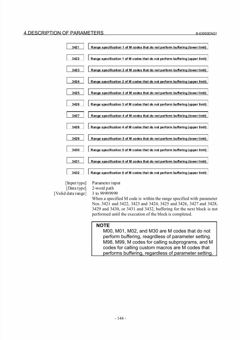
8/21/2019 30i Parameter Manual
http://slidepdf.com/reader/full/30i-parameter-manual 156/493
4.DESCRIPTION OF PARAMETERS B-63950EN/01
- 144 -
3421 Range specification 1 of M codes that do not perform buffering (lower limit)
3422 Range specification 1 of M codes that do not perform buffering (upper limit)
3423 Range specification 2 of M codes that do not perform buffering (lower limit)
3424 Range specification 2 of M codes that do not perform buffering (upper limit)
3425 Range specification 3 of M codes that do not perform buffering (lower limit)
3426 Range specification 3 of M codes that do not perform buffering (upper limit)
3427 Range specification 4 of M codes that do not perform buffering (lower limit)
3428 Range specification 4 of M codes that do not perform buffering (upper limit)
3429 Range specification 5 of M codes that do not perform buffering (lower limit)
3430 Range specification 5 of M codes that do not perform buffering (upper limit)
3431 Range specification 6 of M codes that do not perform buffering (lower limit)
3432 Range specification 6 of M codes that do not perform buffering (upper limit)
[Input type] Parameter input
[Data type] 2-word path
[Valid data range] 3 to 99999999
When a specified M code is within the range specified with parameter
Nos. 3421 and 3422, 3423 and 3424, 3425 and 3426, 3427 and 3428,
3429 and 3430, or 3431 and 3432, buffering for the next block is not
performed until the execution of the block is completed.
NOTEM00, M01, M02, and M30 are M codes that do not
perform buffering, reagrdless of parameter setting.M98, M99, M codes for calling subprograms, and Mcodes for calling custom macros are M codes thatperforms buffering, regardless of parameter setting.
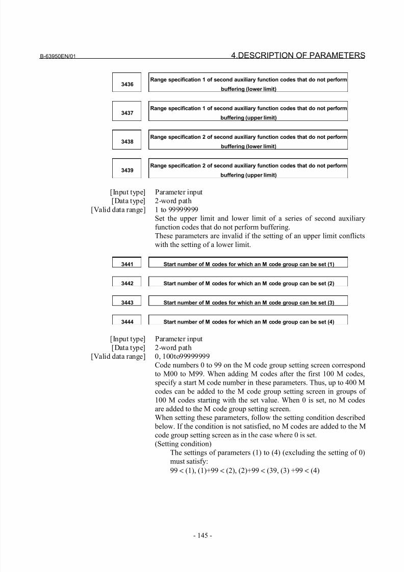
8/21/2019 30i Parameter Manual
http://slidepdf.com/reader/full/30i-parameter-manual 157/493
B-63950EN/01 4.DESCRIPTION OF PARAMETERS
- 145 -
3436Range specification 1 of second auxiliary function codes that do not perform
buffering (lower limit)
3437Range specification 1 of second auxiliary function codes that do not perform
buffering (upper limit)
3438Range specification 2 of second auxiliary function codes that do not perform
buffering (lower limit)
3439Range specification 2 of second auxiliary function codes that do not perform
buffering (upper limit)
[Input type] Parameter input
[Data type] 2-word path[Valid data range] 1 to 99999999
Set the upper limit and lower limit of a series of second auxiliary
function codes that do not perform buffering.
These parameters are invalid if the setting of an upper limit conflicts
with the setting of a lower limit.
3441 Start number of M codes for which an M code group can be set (1)
3442 Start number of M codes for which an M code group can be set (2)
3443 Start number of M codes for which an M code group can be set (3)
3444 Start number of M codes for which an M code group can be set (4)
[Input type] Parameter input
[Data type] 2-word path
[Valid data range] 0, 100to99999999
Code numbers 0 to 99 on the M code group setting screen correspond
to M00 to M99. When adding M codes after the first 100 M codes,
specify a start M code number in these parameters. Thus, up to 400 M
codes can be added to the M code group setting screen in groups of
100 M codes starting with the set value. When 0 is set, no M codesare added to the M code group setting screen.
When setting these parameters, follow the setting condition described
below. If the condition is not satisfied, no M codes are added to the M
code group setting screen as in the case where 0 is set.
(Setting condition)
The settings of parameters (1) to (4) (excluding the setting of 0)
must satisfy:
99 < (1), (1)+99 < (2), (2)+99 < (39, (3) +99 < (4)
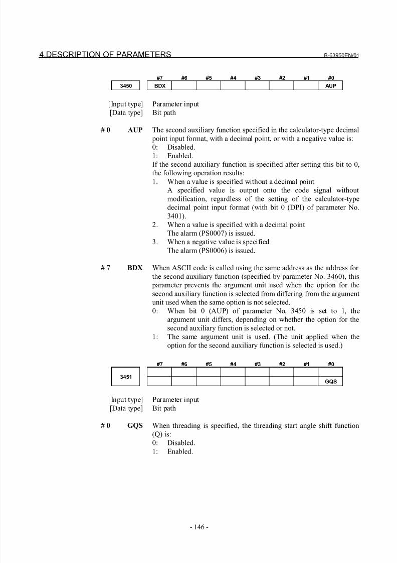
8/21/2019 30i Parameter Manual
http://slidepdf.com/reader/full/30i-parameter-manual 158/493
4.DESCRIPTION OF PARAMETERS B-63950EN/01
- 146 -
#7 #6 #5 #4 #3 #2 #1 #0
3450 BDX AUP
[Input type] Parameter input
[Data type] Bit path
# 0 AUP The second auxiliary function specified in the calculator-type decimal
point input format, with a decimal point, or with a negative value is:
0: Disabled.
1: Enabled.
If the second auxiliary function is specified after setting this bit to 0,
the following operation results:
1. When a value is specified without a decimal point
A specified value is output onto the code signal without
modification, regardless of the setting of the calculator-typedecimal point input format (with bit 0 (DPI) of parameter No.
3401).
2. When a value is specified with a decimal point
The alarm (PS0007) is issued.
3. When a negative value is specified
The alarm (PS0006) is issued.
# 7 BDX When ASCII code is called using the same address as the address for
the second auxiliary function (specified by parameter No. 3460), this
parameter prevents the argument unit used when the option for the
second auxiliary function is selected from differing from the argumentunit used when the same option is not selected.
0: When bit 0 (AUP) of parameter No. 3450 is set to 1, the
argument unit differs, depending on whether the option for the
second auxiliary function is selected or not.
1: The same argument unit is used. (The unit applied when the
option for the second auxiliary function is selected is used.)
#7 #6 #5 #4 #3 #2 #1 #0
3451GQS
[Input type] Parameter input
[Data type] Bit path
# 0 GQS When threading is specified, the threading start angle shift function
(Q) is:
0: Disabled.
1: Enabled.
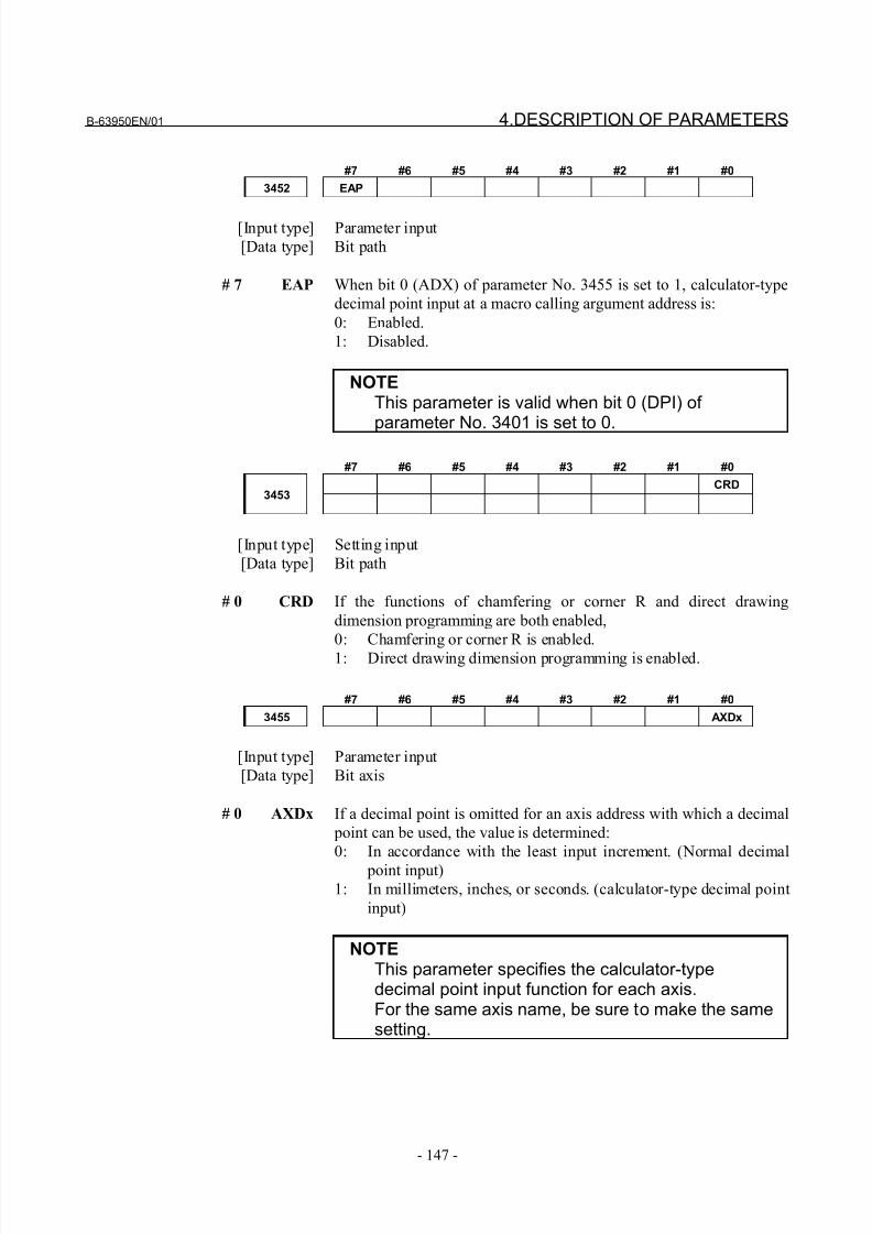
8/21/2019 30i Parameter Manual
http://slidepdf.com/reader/full/30i-parameter-manual 159/493
B-63950EN/01 4.DESCRIPTION OF PARAMETERS
- 147 -
#7 #6 #5 #4 #3 #2 #1 #0
3452 EAP
[Input type] Parameter input
[Data type] Bit path
# 7 EAP When bit 0 (ADX) of parameter No. 3455 is set to 1, calculator-type
decimal point input at a macro calling argument address is:
0: Enabled.
1: Disabled.
NOTEThis parameter is valid when bit 0 (DPI) of parameter No. 3401 is set to 0.
#7 #6 #5 #4 #3 #2 #1 #0
CRD3453
[Input type] Setting input
[Data type] Bit path
# 0 CRD If the functions of chamfering or corner R and direct drawing
dimension programming are both enabled,
0: Chamfering or corner R is enabled.
1: Direct drawing dimension programming is enabled.
#7 #6 #5 #4 #3 #2 #1 #0
3455 AXDx
[Input type] Parameter input
[Data type] Bit axis
# 0 AXDx If a decimal point is omitted for an axis address with which a decimal
point can be used, the value is determined:
0: In accordance with the least input increment. (Normal decimal
point input)1: In millimeters, inches, or seconds. (calculator-type decimal point
input)
NOTEThis parameter specifies the calculator-typedecimal point input function for each axis.For the same axis name, be sure to make the samesetting.
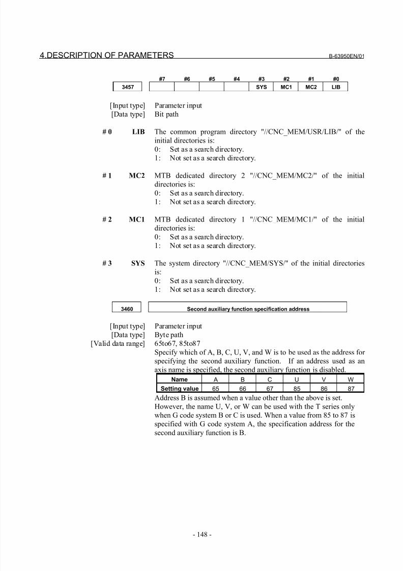
8/21/2019 30i Parameter Manual
http://slidepdf.com/reader/full/30i-parameter-manual 160/493
4.DESCRIPTION OF PARAMETERS B-63950EN/01
- 148 -
#7 #6 #5 #4 #3 #2 #1 #0
3457 SYS MC1 MC2 LIB
[Input type] Parameter input
[Data type] Bit path
# 0 LIB The common program directory "//CNC_MEM/USR/LIB/" of the
initial directories is:
0: Set as a search directory.
1: Not set as a search directory.
# 1 MC2 MTB dedicated directory 2 "//CNC_MEM/MC2/" of the initial
directories is:
0: Set as a search directory.
1: Not set as a search directory.
# 2 MC1 MTB dedicated directory 1 "//CNC_MEM/MC1/" of the initial
directories is:
0: Set as a search directory.
1: Not set as a search directory.
# 3 SYS The system directory "//CNC_MEM/SYS/" of the initial directories
is:
0: Set as a search directory.
1: Not set as a search directory.
3460 Second auxiliary function specification address
[Input type] Parameter input
[Data type] Byte path
[Valid data range] 65to67, 85to87
Specify which of A, B, C, U, V, and W is to be used as the address for
specifying the second auxiliary function. If an address used as an
axis name is specified, the second auxiliary function is disabled.
Name A B C U V W
Setting value 65 66 67 85 86 87
Address B is assumed when a value other than the above is set.However, the name U, V, or W can be used with the T series only
when G code system B or C is used. When a value from 85 to 87 is
specified with G code system A, the specification address for the
second auxiliary function is B.
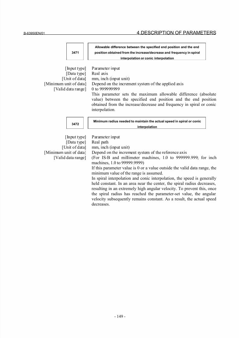
8/21/2019 30i Parameter Manual
http://slidepdf.com/reader/full/30i-parameter-manual 161/493
B-63950EN/01 4.DESCRIPTION OF PARAMETERS
- 149 -
3471
Allowable difference between the specified end position and the end
position obtained from the increase/decrease and frequency in spiral
interpolation or conic interpolation
[Input type] Parameter input
[Data type] Real axis
[Unit of data] mm, inch (input unit)
[Minimum unit of data] Depend on the increment system of the applied axis
[Valid data range] 0 to 999999999
This parameter sets the maximum allowable difference (absolute
value) between the specified end position and the end position
obtained from the increase/decrease and frequency in spiral or conic
interpolation.
3472Minimum radius needed to maintain the actual speed in spiral or conic
interpolation
[Input type] Parameter input
[Data type] Real path
[Unit of data] mm, inch (input unit)
[Minimum unit of data] Depend on the increment system of the reference axis
[Valid data range] (For IS-B and millimeter machines, 1.0 to 999999.999; for inch
machines, 1.0 to 99999.9999)
If this parameter value is 0 or a value outside the valid data range, the
minimum value of the range is assumed.
In spiral interpolation and conic interpolation, the speed is generallyheld constant. In an area near the center, the spiral radius decreases,
resulting in an extremely high angular velocity. To prevent this, once
the spiral radius has reached the parameter-set value, the angular
velocity subsequently remains constant. As a result, the actual speed
decreases.
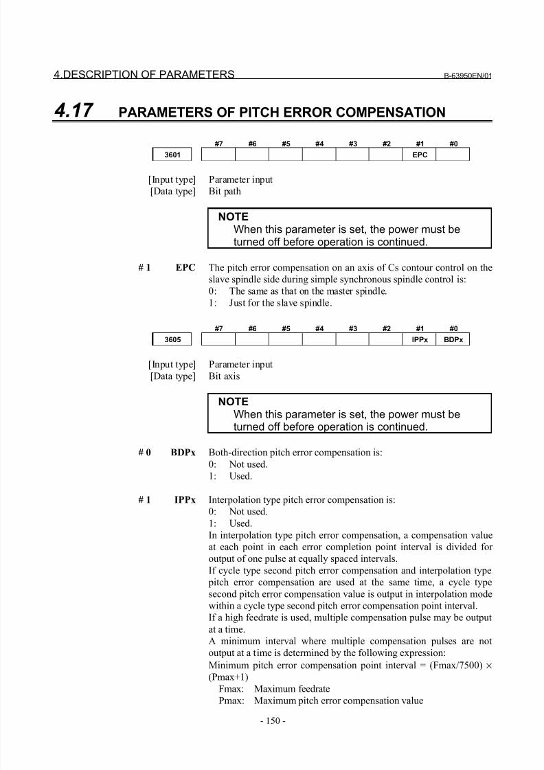
8/21/2019 30i Parameter Manual
http://slidepdf.com/reader/full/30i-parameter-manual 162/493
4.DESCRIPTION OF PARAMETERS B-63950EN/01
- 150 -
4.17 PARAMETERS OF PITCH ERROR COMPENSATION
#7 #6 #5 #4 #3 #2 #1 #0
3601 EPC
[Input type] Parameter input
[Data type] Bit path
NOTEWhen this parameter is set, the power must beturned off before operation is continued.
# 1 EPC The pitch error compensation on an axis of Cs contour control on theslave spindle side during simple synchronous spindle control is:
0: The same as that on the master spindle.
1: Just for the slave spindle.
#7 #6 #5 #4 #3 #2 #1 #0
3605 IPPx BDPx
[Input type] Parameter input
[Data type] Bit axis
NOTEWhen this parameter is set, the power must beturned off before operation is continued.
# 0 BDPx Both-direction pitch error compensation is:
0: Not used.
1: Used.
# 1 IPPx Interpolation type pitch error compensation is:
0: Not used.
1: Used.
In interpolation type pitch error compensation, a compensation valueat each point in each error completion point interval is divided for
output of one pulse at equally spaced intervals.
If cycle type second pitch error compensation and interpolation type
pitch error compensation are used at the same time, a cycle type
second pitch error compensation value is output in interpolation mode
within a cycle type second pitch error compensation point interval.
If a high feedrate is used, multiple compensation pulse may be output
at a time.
A minimum interval where multiple compensation pulses are not
output at a time is determined by the following expression:
Minimum pitch error compensation point interval = (Fmax/7500) ×
(Pmax+1) Fmax: Maximum feedrate
Pmax: Maximum pitch error compensation value
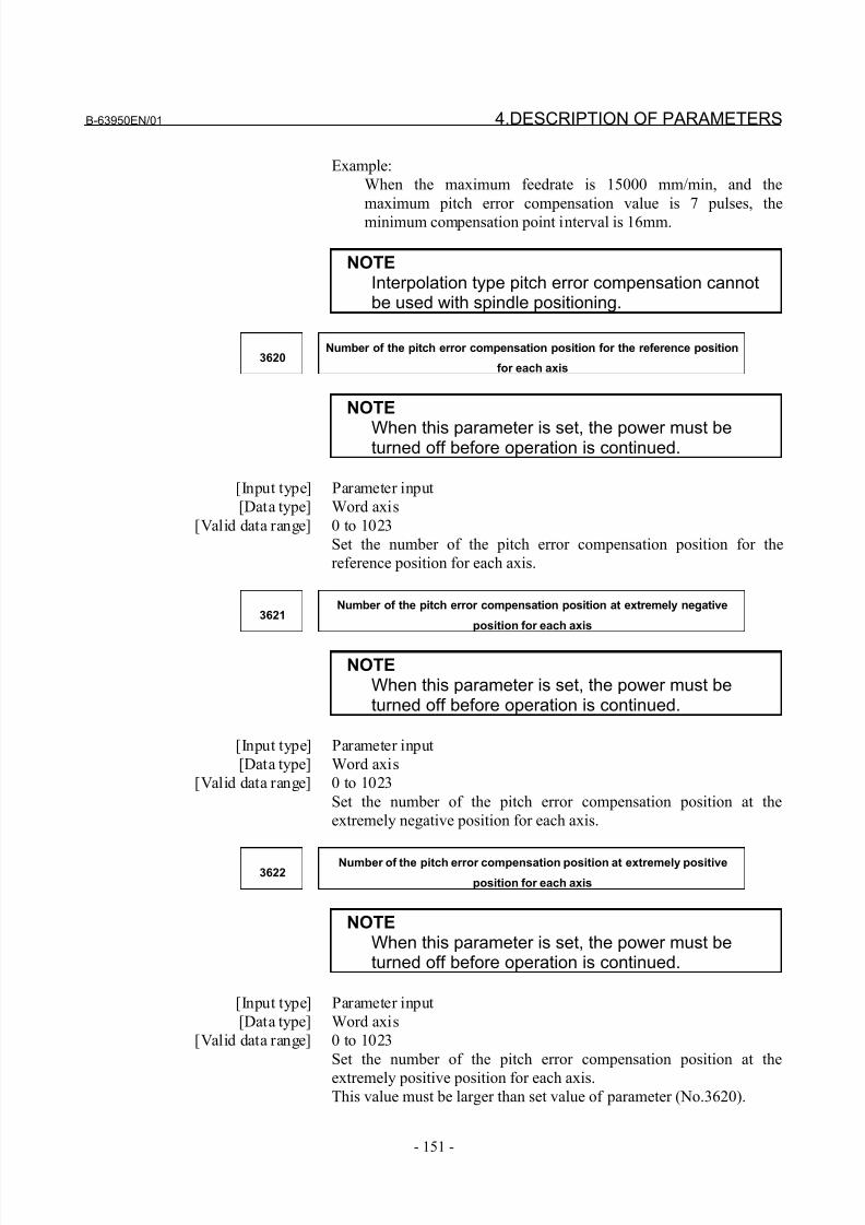
8/21/2019 30i Parameter Manual
http://slidepdf.com/reader/full/30i-parameter-manual 163/493
B-63950EN/01 4.DESCRIPTION OF PARAMETERS
- 151 -
Example:
When the maximum feedrate is 15000 mm/min, and the
maximum pitch error compensation value is 7 pulses, the
minimum compensation point interval is 16mm.
NOTEInterpolation type pitch error compensation cannotbe used with spindle positioning.
3620Number of the pitch error compensation position for the reference position
for each axis
NOTE
When this parameter is set, the power must beturned off before operation is continued.
[Input type] Parameter input
[Data type] Word axis
[Valid data range] 0 to 1023
Set the number of the pitch error compensation position for the
reference position for each axis.
3621Number of the pitch error compensation position at extremely negative
position for each axis
NOTEWhen this parameter is set, the power must beturned off before operation is continued.
[Input type] Parameter input
[Data type] Word axis
[Valid data range] 0 to 1023
Set the number of the pitch error compensation position at the
extremely negative position for each axis.
3622Number of the pitch error compensation position at extremely positive
position for each axis
NOTEWhen this parameter is set, the power must beturned off before operation is continued.
[Input type] Parameter input
[Data type] Word axis
[Valid data range] 0 to 1023
Set the number of the pitch error compensation position at the
extremely positive position for each axis.This value must be larger than set value of parameter (No.3620).
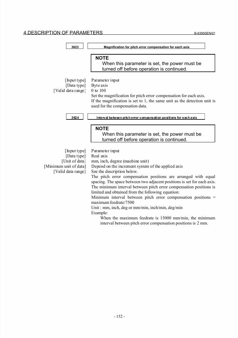
8/21/2019 30i Parameter Manual
http://slidepdf.com/reader/full/30i-parameter-manual 164/493
4.DESCRIPTION OF PARAMETERS B-63950EN/01
- 152 -
3623 Magnification for pitch error compensation for each axis
NOTEWhen this parameter is set, the power must beturned off before operation is continued.
[Input type] Parameter input
[Data type] Byte axis
[Valid data range] 0 to 100
Set the magnification for pitch error compensation for each axis.
If the magnification is set to 1, the same unit as the detection unit is
used for the compensation data.
3624 Interval between pitch error compensation positions for each axis
NOTEWhen this parameter is set, the power must beturned off before operation is continued.
[Input type] Parameter input
[Data type] Real axis
[Unit of data] mm, inch, degree (machine unit)
[Minimum unit of data] Depend on the increment system of the applied axis
[Valid data range] See the description below.
The pitch error compensation positions are arranged with equalspacing. The space between two adjacent positions is set for each axis.
The minimum interval between pitch error compensation positions is
limited and obtained from the following equation:
Minimum interval between pitch error compensation positions =
maximum feedrate/7500
Unit : mm, inch, deg or mm/min, inch/min, deg/min
Example:
When the maximum feedrate is 15000 mm/min, the minimum
interval between pitch error compensation positions is 2 mm.
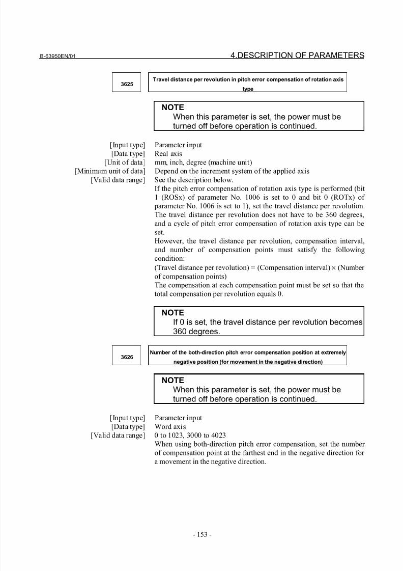
8/21/2019 30i Parameter Manual
http://slidepdf.com/reader/full/30i-parameter-manual 165/493
B-63950EN/01 4.DESCRIPTION OF PARAMETERS
- 153 -
3625Travel distance per revolution in pitch error compensation of rotation axis
type
NOTEWhen this parameter is set, the power must beturned off before operation is continued.
[Input type] Parameter input
[Data type] Real axis
[Unit of data] mm, inch, degree (machine unit)
[Minimum unit of data] Depend on the increment system of the applied axis
[Valid data range] See the description below.
If the pitch error compensation of rotation axis type is performed (bit
1 (ROSx) of parameter No. 1006 is set to 0 and bit 0 (ROTx) of parameter No. 1006 is set to 1), set the travel distance per revolution.
The travel distance per revolution does not have to be 360 degrees,
and a cycle of pitch error compensation of rotation axis type can be
set.
However, the travel distance per revolution, compensation interval,
and number of compensation points must satisfy the following
condition:
(Travel distance per revolution) = (Compensation interval) × (Number
of compensation points)
The compensation at each compensation point must be set so that the
total compensation per revolution equals 0.
NOTEIf 0 is set, the travel distance per revolution becomes360 degrees.
3626Number of the both-direction pitch error compensation position at extremely
negative position (for movement in the negative direction)
NOTEWhen this parameter is set, the power must be
turned off before operation is continued.
[Input type] Parameter input
[Data type] Word axis
[Valid data range] 0 to 1023, 3000 to 4023
When using both-direction pitch error compensation, set the number
of compensation point at the farthest end in the negative direction for
a movement in the negative direction.
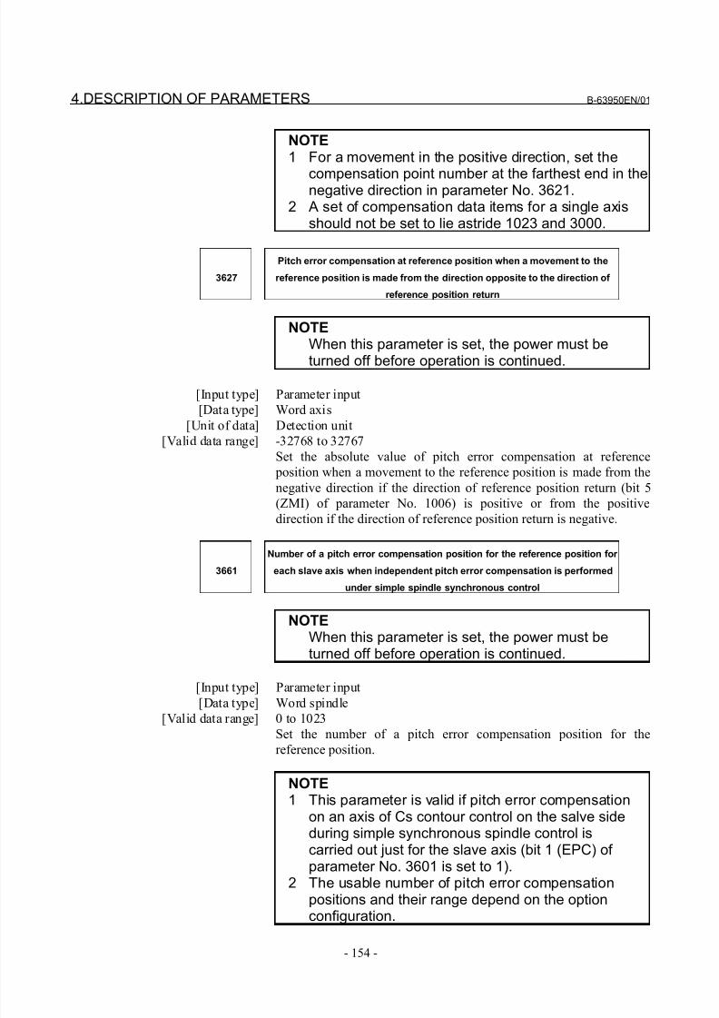
8/21/2019 30i Parameter Manual
http://slidepdf.com/reader/full/30i-parameter-manual 166/493
4.DESCRIPTION OF PARAMETERS B-63950EN/01
- 154 -
NOTE1 For a movement in the positive direction, set the
compensation point number at the farthest end in thenegative direction in parameter No. 3621.2 A set of compensation data items for a single axis
should not be set to lie astride 1023 and 3000.
3627
Pitch error compensation at reference position when a movement to the
reference position is made from the direction opposite to the direction of
reference position return
NOTEWhen this parameter is set, the power must be
turned off before operation is continued.
[Input type] Parameter input
[Data type] Word axis
[Unit of data] Detection unit
[Valid data range] -32768 to 32767
Set the absolute value of pitch error compensation at reference
position when a movement to the reference position is made from the
negative direction if the direction of reference position return (bit 5
(ZMI) of parameter No. 1006) is positive or from the positive
direction if the direction of reference position return is negative.
3661
Number of a pitch error compensation position for the reference position for
each slave axis when independent pitch error compensation is performed
under simple spindle synchronous control
NOTEWhen this parameter is set, the power must beturned off before operation is continued.
[Input type] Parameter input
[Data type] Word spindle
[Valid data range] 0 to 1023
Set the number of a pitch error compensation position for the
reference position.
NOTE1 This parameter is valid if pitch error compensation
on an axis of Cs contour control on the salve sideduring simple synchronous spindle control iscarried out just for the slave axis (bit 1 (EPC) of parameter No. 3601 is set to 1).
2 The usable number of pitch error compensationpositions and their range depend on the optionconfiguration.
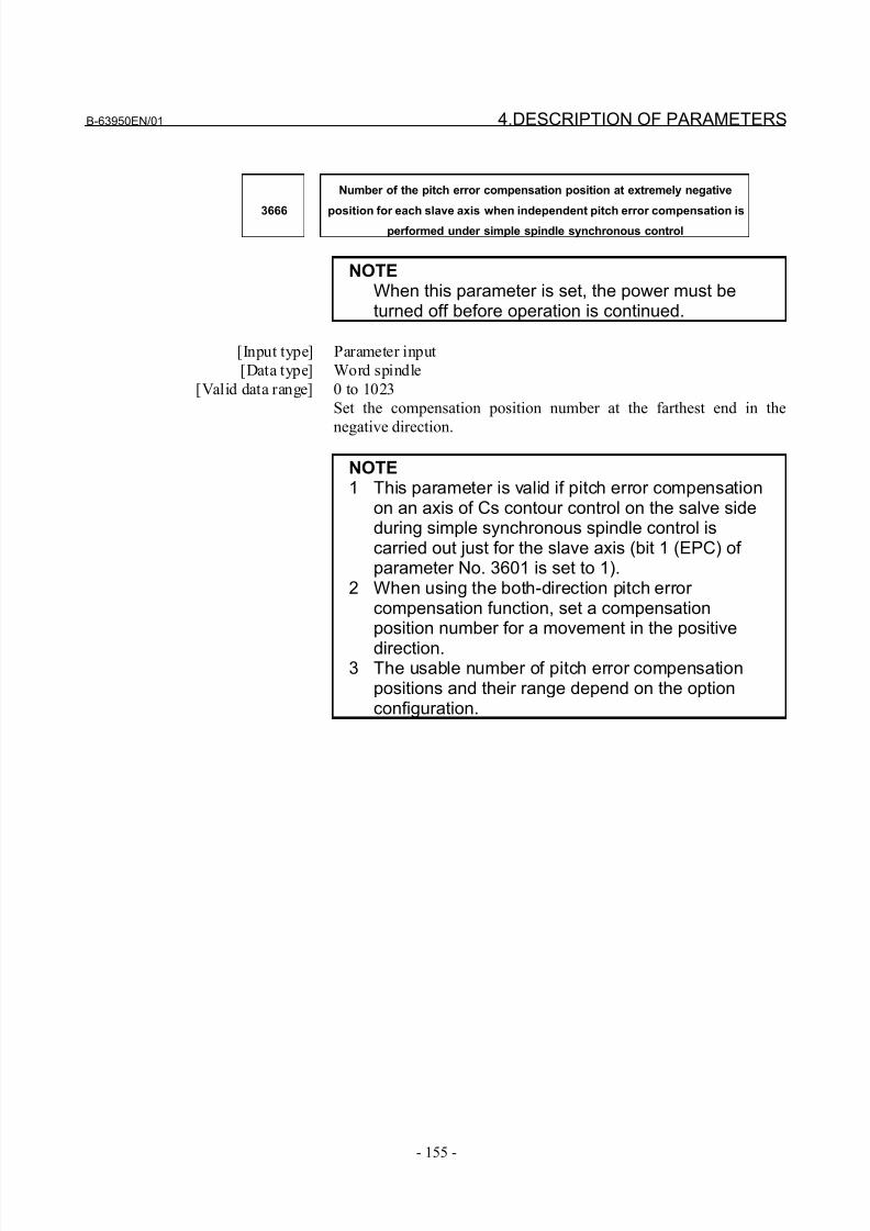
8/21/2019 30i Parameter Manual
http://slidepdf.com/reader/full/30i-parameter-manual 167/493
B-63950EN/01 4.DESCRIPTION OF PARAMETERS
- 155 -
3666
Number of the pitch error compensation position at extremely negative
position for each slave axis when independent pitch error compensation isperformed under simple spindle synchronous control
NOTEWhen this parameter is set, the power must beturned off before operation is continued.
[Input type] Parameter input
[Data type] Word spindle
[Valid data range] 0 to 1023
Set the compensation position number at the farthest end in the
negative direction.
NOTE1 This parameter is valid if pitch error compensation
on an axis of Cs contour control on the salve sideduring simple synchronous spindle control iscarried out just for the slave axis (bit 1 (EPC) of parameter No. 3601 is set to 1).
2 When using the both-direction pitch error compensation function, set a compensationposition number for a movement in the positive
direction.3 The usable number of pitch error compensation
positions and their range depend on the optionconfiguration.
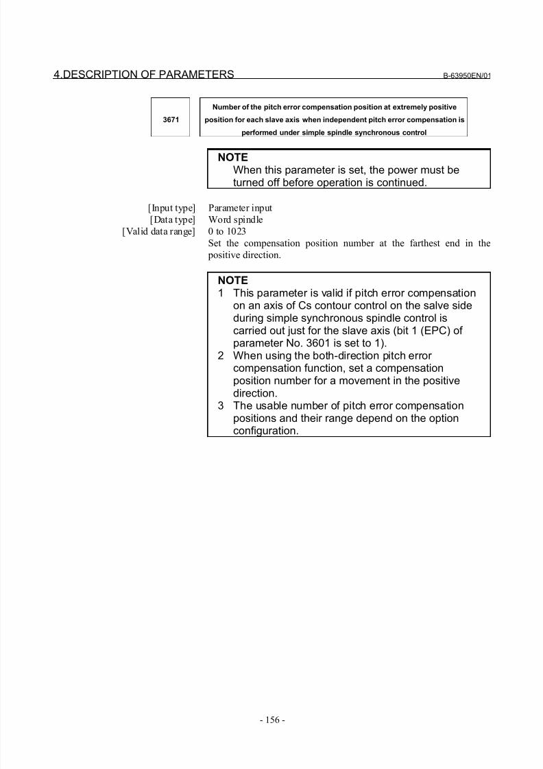
8/21/2019 30i Parameter Manual
http://slidepdf.com/reader/full/30i-parameter-manual 168/493
4.DESCRIPTION OF PARAMETERS B-63950EN/01
- 156 -
3671
Number of the pitch error compensation position at extremely positive
position for each slave axis when independent pitch error compensation is
performed under simple spindle synchronous control
NOTEWhen this parameter is set, the power must beturned off before operation is continued.
[Input type] Parameter input
[Data type] Word spindle
[Valid data range] 0 to 1023
Set the compensation position number at the farthest end in the
positive direction.
NOTE1 This parameter is valid if pitch error compensation
on an axis of Cs contour control on the salve sideduring simple synchronous spindle control iscarried out just for the slave axis (bit 1 (EPC) of parameter No. 3601 is set to 1).
2 When using the both-direction pitch error compensation function, set a compensationposition number for a movement in the positivedirection.
3 The usable number of pitch error compensationpositions and their range depend on the optionconfiguration.
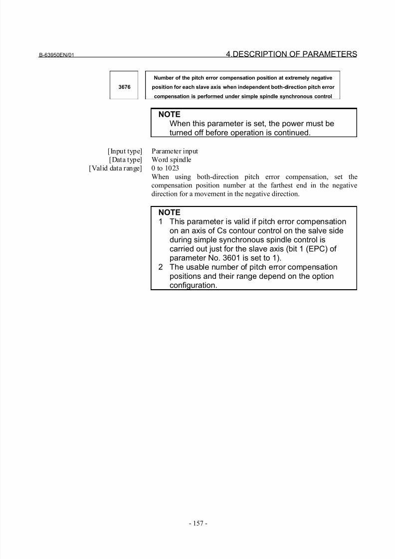
8/21/2019 30i Parameter Manual
http://slidepdf.com/reader/full/30i-parameter-manual 169/493
B-63950EN/01 4.DESCRIPTION OF PARAMETERS
- 157 -
3676
Number of the pitch error compensation position at extremely negative
position for each slave axis when independent both-direction pitch error
compensation is performed under simple spindle synchronous control
NOTEWhen this parameter is set, the power must beturned off before operation is continued.
[Input type] Parameter input
[Data type] Word spindle
[Valid data range] 0 to 1023
When using both-direction pitch error compensation, set the
compensation position number at the farthest end in the negative
direction for a movement in the negative direction.
NOTE1 This parameter is valid if pitch error compensation
on an axis of Cs contour control on the salve sideduring simple synchronous spindle control iscarried out just for the slave axis (bit 1 (EPC) of parameter No. 3601 is set to 1).
2 The usable number of pitch error compensationpositions and their range depend on the optionconfiguration.
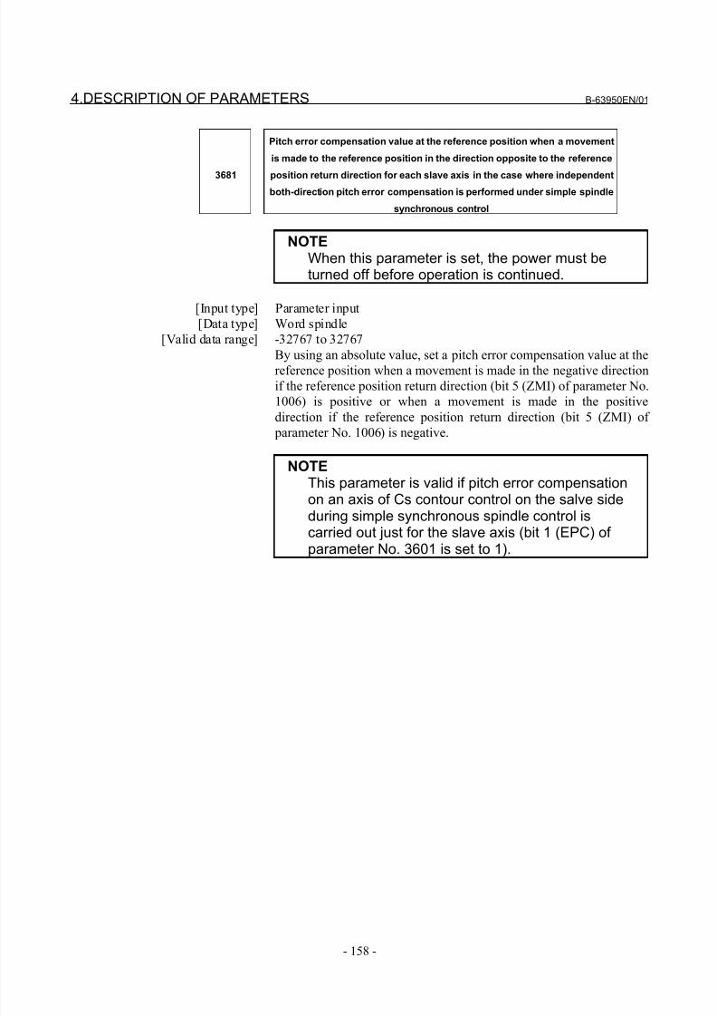
8/21/2019 30i Parameter Manual
http://slidepdf.com/reader/full/30i-parameter-manual 170/493
4.DESCRIPTION OF PARAMETERS B-63950EN/01
- 158 -
3681
Pitch error compensation value at the reference position when a movement
is made to the reference position in the direction opposite to the reference
position return direction for each slave axis in the case where independentboth-direction pitch error compensation is performed under simple spindle
synchronous control
NOTEWhen this parameter is set, the power must beturned off before operation is continued.
[Input type] Parameter input
[Data type] Word spindle
[Valid data range] -32767 to 32767
By using an absolute value, set a pitch error compensation value at thereference position when a movement is made in the negative direction
if the reference position return direction (bit 5 (ZMI) of parameter No.
1006) is positive or when a movement is made in the positive
direction if the reference position return direction (bit 5 (ZMI) of
parameter No. 1006) is negative.
NOTEThis parameter is valid if pitch error compensationon an axis of Cs contour control on the salve sideduring simple synchronous spindle control is
carried out just for the slave axis (bit 1 (EPC) of parameter No. 3601 is set to 1).
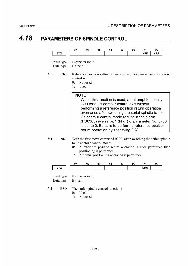
8/21/2019 30i Parameter Manual
http://slidepdf.com/reader/full/30i-parameter-manual 171/493
B-63950EN/01 4.DESCRIPTION OF PARAMETERS
- 159 -
4.18 PARAMETERS OF SPINDLE CONTROL
#7 #6 #5 #4 #3 #2 #1 #0
3700 NRF CRF
[Input type] Parameter input
[Data type] Bit path
# 0 CRF Reference position setting at an arbitrary position under Cs contour
control is:
0: Not used.
1: Used.
NOTEWhen this function is used, an attempt to specifyG00 for a Cs contour control axis withoutperforming a reference position return operationeven once after switching the serial spindle to theCs contour control mode results in the alarm(PS0303) even if bit 1 (NRF) of parameter No. 3700is set to 0. Be sure to perform a reference positionreturn operation by specifying G28.
# 1 NRF With the first move command (G00) after switching the series spindleto Cs contour control mode:
0: A reference position return operation is once performed then
positioning is performed.
1: A normal positioning operation is performed.
#7 #6 #5 #4 #3 #2 #1 #0
3702 EMS
[Input type] Parameter input
[Data type] Bit path
# 1 EMS The multi-spindle control function is:
0: Used.
1: Not used.
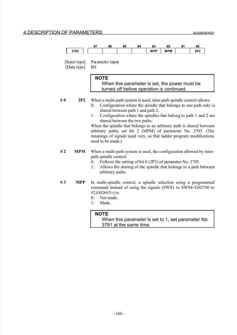
8/21/2019 30i Parameter Manual
http://slidepdf.com/reader/full/30i-parameter-manual 172/493
4.DESCRIPTION OF PARAMETERS B-63950EN/01
- 160 -
#7 #6 #5 #4 #3 #2 #1 #0
3703 MPP MPM 2P2
[Input type] Parameter input
[Data type] Bit
NOTEWhen this parameter is set, the power must beturned off before operation is continued.
# 0 2P2 When a multi-path system is used, inter-path spindle control allows:
0: Configuration where the spindle that belongs to one path only is
shared between path 1 and path 2.
1: Configuration where the spindles that belong to path 1 and 2 areshared between the two paths.
When the spindle that belongs to an arbitrary path is shared between
arbitrary paths, set bit 2 (MPM) of parameter No. 3703. (The
meanings of signals used vary, so that ladder program modifications
need to be made.)
# 2 MPM When a multi-path system is used, the configuration allowed by inter-
path spindle control:
0: Follows the setting of bit 0 (2P2) of parameter No. 3703.
1: Allows the sharing of the spindle that belongs to a path between
arbitrary paths.
# 3 MPP In multi-spindle control, a spindle selection using a programmed
command instead of using the signals (SWS1 to SWS4<G027#0 to
#2,G026#3>) is:
0: Not made.
1: Made.
NOTEWhen this parameter is set to 1, set parameter No.3781 at the same time.
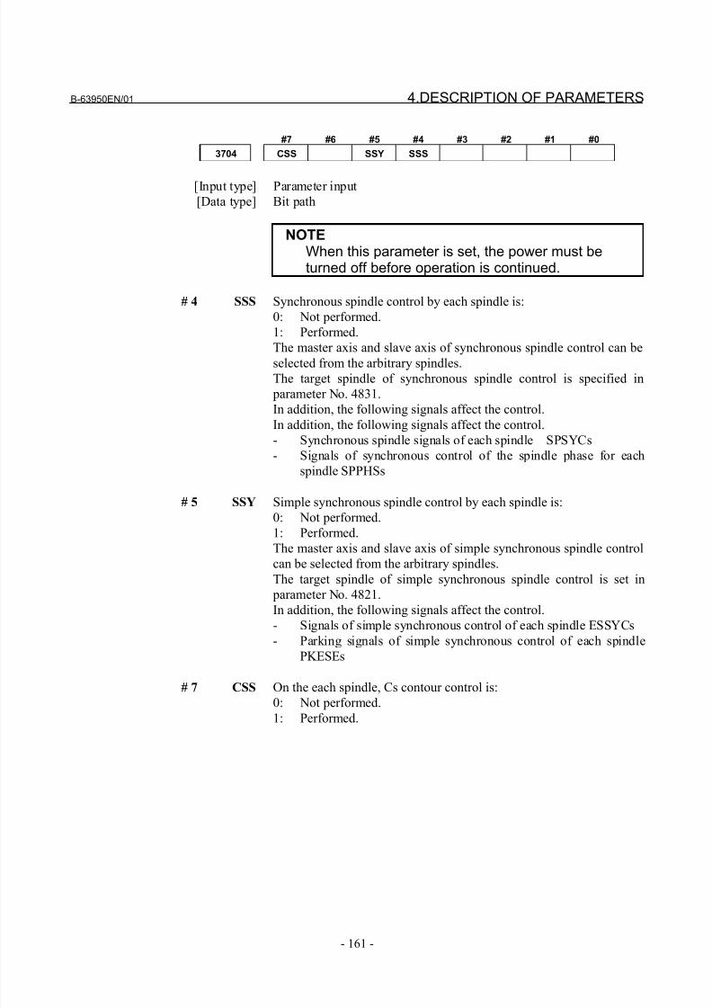
8/21/2019 30i Parameter Manual
http://slidepdf.com/reader/full/30i-parameter-manual 173/493
B-63950EN/01 4.DESCRIPTION OF PARAMETERS
- 161 -
#7 #6 #5 #4 #3 #2 #1 #0
3704 CSS SSY SSS
[Input type] Parameter input
[Data type] Bit path
NOTEWhen this parameter is set, the power must beturned off before operation is continued.
# 4 SSS Synchronous spindle control by each spindle is:
0: Not performed.
1: Performed.
The master axis and slave axis of synchronous spindle control can beselected from the arbitrary spindles.
The target spindle of synchronous spindle control is specified in
parameter No. 4831.
In addition, the following signals affect the control.
In addition, the following signals affect the control.
- Synchronous spindle signals of each spindle SPSYCs
- Signals of synchronous control of the spindle phase for each
spindle SPPHSs
# 5 SSY Simple synchronous spindle control by each spindle is:
0: Not performed.
1: Performed.The master axis and slave axis of simple synchronous spindle control
can be selected from the arbitrary spindles.
The target spindle of simple synchronous spindle control is set in
parameter No. 4821.
In addition, the following signals affect the control.
- Signals of simple synchronous control of each spindle ESSYCs
- Parking signals of simple synchronous control of each spindle
PKESEs
# 7 CSS On the each spindle, Cs contour control is:
0: Not performed.1: Performed.
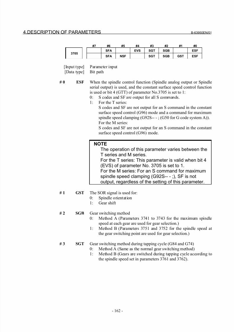
8/21/2019 30i Parameter Manual
http://slidepdf.com/reader/full/30i-parameter-manual 174/493
4.DESCRIPTION OF PARAMETERS B-63950EN/01
- 162 -
#7 #6 #5 #4 #3 #2 #1 #0
SFA EVS SGT SGB ESF3705
SFA NSF SGT SGB GST ESF
[Input type] Parameter input
[Data type] Bit path
# 0 ESF When the spindle control function (Spindle analog output or Spindle
serial output) is used, and the constant surface speed control function
is used or bit 4 (GTT) of parameter No.3705 is set to 1:
0: S codes and SF are output for all S commands.
1: For the T series:
S codes and SF are not output for an S command in the constant
surface speed control (G96) mode and a command for maximum
spindle speed clamping (G92S-- - ; (G50 for G code system A)).For the M series:
S codes and SF are not output for an S command in the constant
surface speed control (G96) mode.
NOTEThe operation of this parameter varies between theT series and M series.For the T series: This parameter is valid when bit 4(EVS) of parameter No. 3705 is set to 1.For the M series: For an S command for maximumspindle speed clamping (G92S-- - ;), SF is notoutput, regardless of the setting of this parameter.
# 1 GST The SOR signal is used for:
0: Spindle orientation
1: Gear shift
# 2 SGB Gear switching method
0: Method A (Parameters 3741 to 3743 for the maximum spindle
speed at each gear are used for gear selection.)
1: Method B (Parameters 3751 and 3752 for the spindle speed at
the gear switching point are used for gear selection.)
# 3 SGT Gear switching method during tapping cycle (G84 and G74)
0: Method A (Same as the normal gear switching method)
1: Method B (Gears are switched during tapping cycle according to
the spindle speed set in parameters 3761 and 3762).
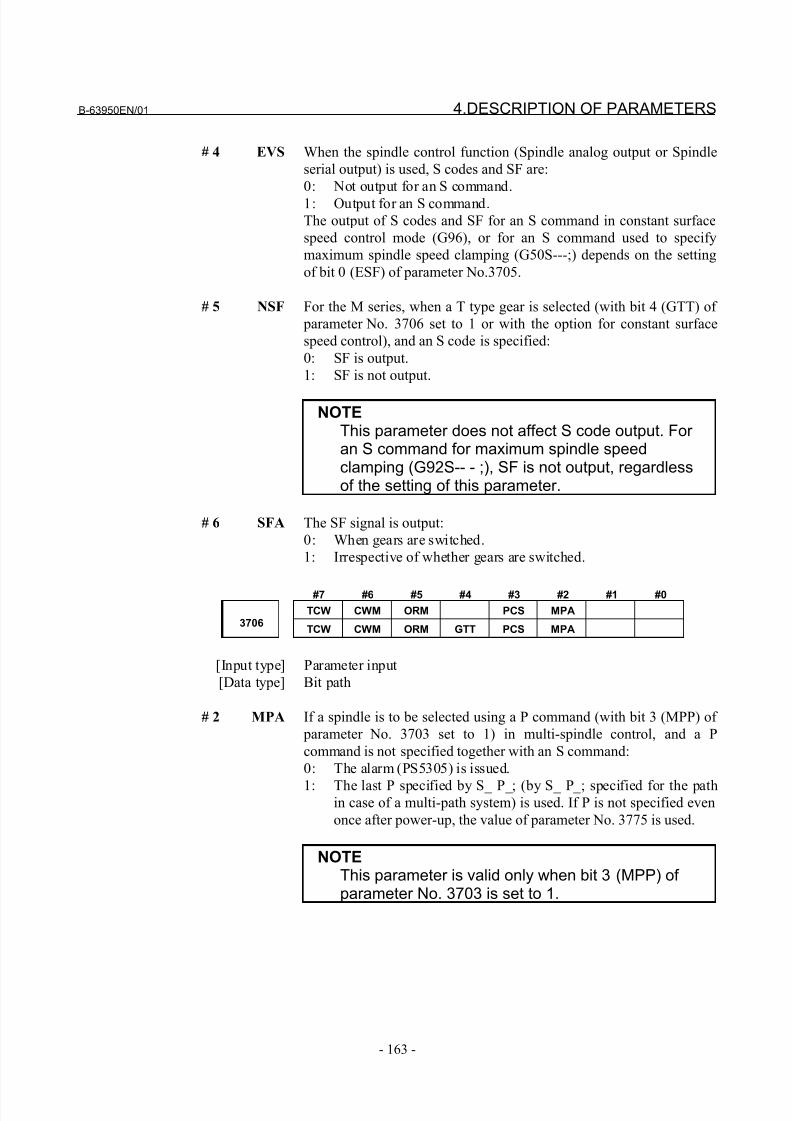
8/21/2019 30i Parameter Manual
http://slidepdf.com/reader/full/30i-parameter-manual 175/493
B-63950EN/01 4.DESCRIPTION OF PARAMETERS
- 163 -
# 4 EVS When the spindle control function (Spindle analog output or Spindle
serial output) is used, S codes and SF are:
0: Not output for an S command.
1: Output for an S command.
The output of S codes and SF for an S command in constant surface
speed control mode (G96), or for an S command used to specify
maximum spindle speed clamping (G50S---;) depends on the setting
of bit 0 (ESF) of parameter No.3705.
# 5 NSF For the M series, when a T type gear is selected (with bit 4 (GTT) of
parameter No. 3706 set to 1 or with the option for constant surface
speed control), and an S code is specified:
0: SF is output.
1: SF is not output.
NOTEThis parameter does not affect S code output. For an S command for maximum spindle speedclamping (G92S-- - ;), SF is not output, regardlessof the setting of this parameter.
# 6 SFA The SF signal is output:
0: When gears are switched.
1: Irrespective of whether gears are switched.
#7 #6 #5 #4 #3 #2 #1 #0
TCW CWM ORM PCS MPA3706
TCW CWM ORM GTT PCS MPA
[Input type] Parameter input
[Data type] Bit path
# 2 MPA If a spindle is to be selected using a P command (with bit 3 (MPP) of
parameter No. 3703 set to 1) in multi-spindle control, and a P
command is not specified together with an S command:
0: The alarm (PS5305) is issued.
1: The last P specified by S_ P_; (by S_ P_; specified for the pathin case of a multi-path system) is used. If P is not specified even
once after power-up, the value of parameter No. 3775 is used.
NOTEThis parameter is valid only when bit 3 (MPP) of parameter No. 3703 is set to 1.
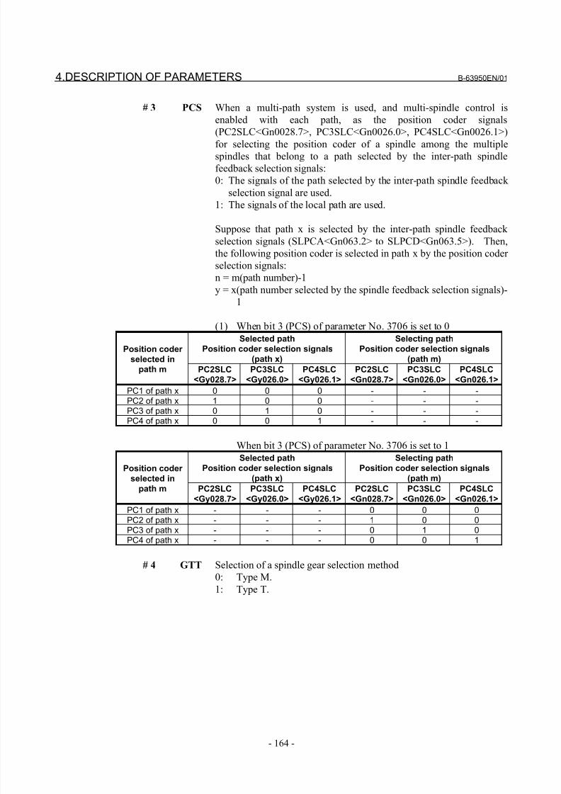
8/21/2019 30i Parameter Manual
http://slidepdf.com/reader/full/30i-parameter-manual 176/493
4.DESCRIPTION OF PARAMETERS B-63950EN/01
- 164 -
# 3 PCS When a multi-path system is used, and multi-spindle control is
enabled with each path, as the position coder signals
(PC2SLC<Gn0028.7>, PC3SLC<Gn0026.0>, PC4SLC<Gn0026.1>)
for selecting the position coder of a spindle among the multiple
spindles that belong to a path selected by the inter-path spindle
feedback selection signals:
0: The signals of the path selected by the inter-path spindle feedback
selection signal are used.
1: The signals of the local path are used.
Suppose that path x is selected by the inter-path spindle feedback
selection signals (SLPCA<Gn063.2> to SLPCD<Gn063.5>). Then,
the following position coder is selected in path x by the position coder
selection signals:
n = m(path number)-1y = x(path number selected by the spindle feedback selection signals)-
1
(1) When bit 3 (PCS) of parameter No. 3706 is set to 0
Selected path
Position coder selection signals
(path x)
Selecting path
Position coder selection signals
(path m)Position coder
selected inpath m PC2SLC
<Gy028.7>
PC3SLC
<Gy026.0>
PC4SLC
<Gy026.1>
PC2SLC
<Gn028.7>
PC3SLC
<Gn026.0>
PC4SLC
<Gn026.1>
PC1 of path x 0 0 0 - - -PC2 of path x 1 0 0 - - -PC3 of path x 0 1 0 - - -PC4 of path x 0 0 1 - - -
When bit 3 (PCS) of parameter No. 3706 is set to 1
Selected path
Position coder selection signals
(path x)
Selecting path
Position coder selection signals
(path m)Position coder
selected in
path m PC2SLC
<Gy028.7>
PC3SLC
<Gy026.0>
PC4SLC
<Gy026.1>
PC2SLC
<Gn028.7>
PC3SLC
<Gn026.0>
PC4SLC
<Gn026.1>
PC1 of path x - - - 0 0 0PC2 of path x - - - 1 0 0PC3 of path x - - - 0 1 0PC4 of path x - - - 0 0 1
# 4 GTT Selection of a spindle gear selection method
0: Type M.
1: Type T.
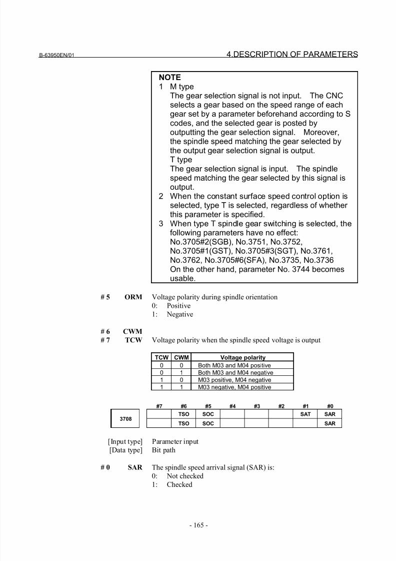
8/21/2019 30i Parameter Manual
http://slidepdf.com/reader/full/30i-parameter-manual 177/493
B-63950EN/01 4.DESCRIPTION OF PARAMETERS
- 165 -
NOTE1 M type
The gear selection signal is not input. The CNCselects a gear based on the speed range of eachgear set by a parameter beforehand according to Scodes, and the selected gear is posted byoutputting the gear selection signal. Moreover,the spindle speed matching the gear selected bythe output gear selection signal is output.T typeThe gear selection signal is input. The spindlespeed matching the gear selected by this signal isoutput.
2 When the constant surface speed control option isselected, type T is selected, regardless of whether this parameter is specified.
3 When type T spindle gear switching is selected, thefollowing parameters have no effect:No.3705#2(SGB), No.3751, No.3752,No.3705#1(GST), No.3705#3(SGT), No.3761,No.3762, No.3705#6(SFA), No.3735, No.3736On the other hand, parameter No. 3744 becomesusable.
# 5 ORM Voltage polarity during spindle orientation0: Positive
1: Negative
# 6 CWM
# 7 TCW Voltage polarity when the spindle speed voltage is output
TCW CWM Voltage polarity
0 0 Both M03 and M04 positive
0 1 Both M03 and M04 negative
1 0 M03 positive, M04 negative
1 1 M03 negative, M04 positive
#7 #6 #5 #4 #3 #2 #1 #0
TSO SOC SAT SAR3708
TSO SOC SAR
[Input type] Parameter input
[Data type] Bit path
# 0 SAR The spindle speed arrival signal (SAR) is:
0: Not checked
1: Checked
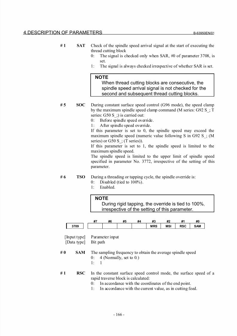
8/21/2019 30i Parameter Manual
http://slidepdf.com/reader/full/30i-parameter-manual 178/493
4.DESCRIPTION OF PARAMETERS B-63950EN/01
- 166 -
# 1 SAT Check of the spindle speed arrival signal at the start of executing the
thread cutting block
0: The signal is checked only when SAR, #0 of parameter 3708, is
set.
1: The signal is always checked irrespective of whether SAR is set.
NOTEWhen thread cutting blocks are consecutive, thespindle speed arrival signal is not checked for thesecond and subsequent thread cutting blocks.
# 5 SOC During constant surface speed control (G96 mode), the speed clamp
by the maximum spindle speed clamp command (M series: G92 S_; T
series: G50 S_;) is carried out:
0: Before spindle speed override.
1: After spindle speed override.
If this parameter is set to 0, the spindle speed may exceed the
maximum spindle speed (numeric value following S in G92 S_; (M
series) or G50 S_; (T series)).
If this parameter is set to 1, the spindle speed is limited to the
maximum spindle speed.
The spindle speed is limited to the upper limit of spindle speed
specified in parameter No. 3772, irrespective of the setting of this
parameter.
# 6 TSO During a threading or tapping cycle, the spindle override is:0: Disabled (tied to 100%).
1: Enabled.
NOTEDuring rigid tapping, the override is tied to 100%,irrespective of the setting of this parameter.
#7 #6 #5 #4 #3 #2 #1 #0
3709 MRS MSI RSC SAM
[Input type] Parameter input[Data type] Bit path
# 0 SAM The sampling frequency to obtain the average spindle speed
0: 4 (Normally, set to 0.)
1: 1
# 1 RSC In the constant surface speed control mode, the surface speed of a
rapid traverse block is calculated:
0: In accordance with the coordinates of the end point.
1: In accordance with the current value, as in cutting feed.
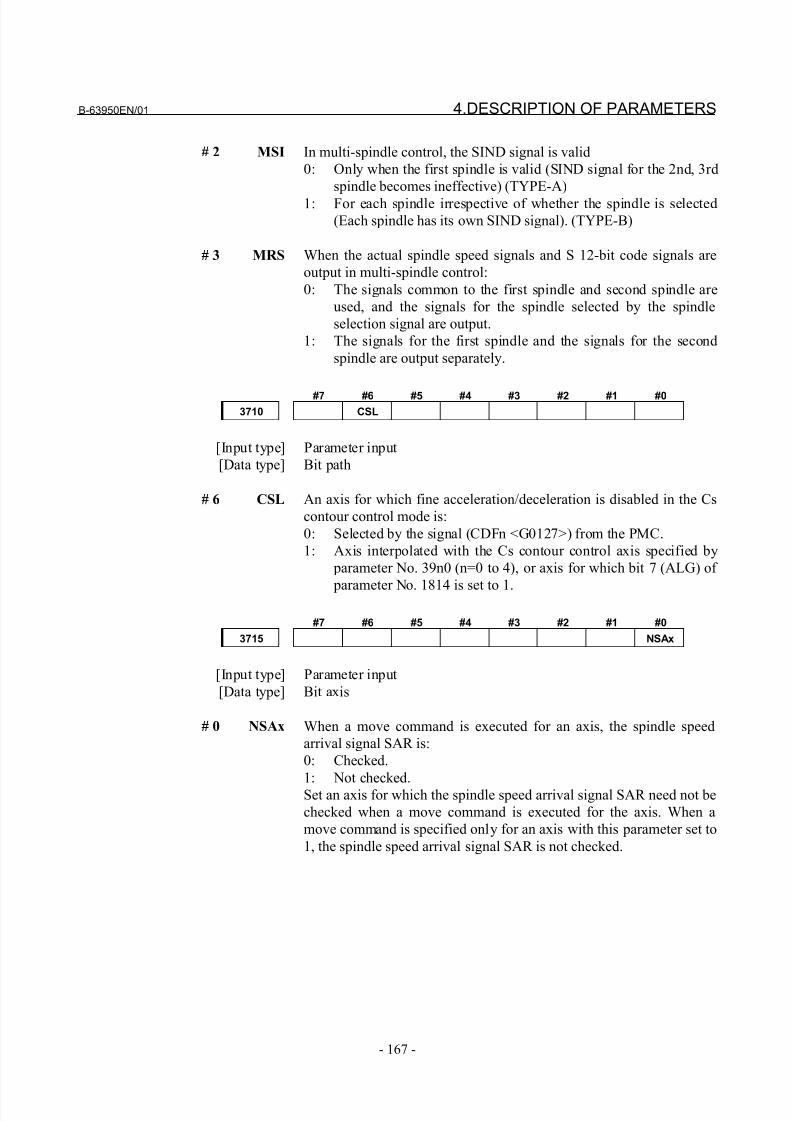
8/21/2019 30i Parameter Manual
http://slidepdf.com/reader/full/30i-parameter-manual 179/493
B-63950EN/01 4.DESCRIPTION OF PARAMETERS
- 167 -
# 2 MSI In multi-spindle control, the SIND signal is valid
0: Only when the first spindle is valid (SIND signal for the 2nd, 3rd
spindle becomes ineffective) (TYPE-A)
1: For each spindle irrespective of whether the spindle is selected
(Each spindle has its own SIND signal). (TYPE-B)
# 3 MRS When the actual spindle speed signals and S 12-bit code signals are
output in multi-spindle control:
0: The signals common to the first spindle and second spindle are
used, and the signals for the spindle selected by the spindle
selection signal are output.
1: The signals for the first spindle and the signals for the second
spindle are output separately.
#7 #6 #5 #4 #3 #2 #1 #0
3710 CSL
[Input type] Parameter input
[Data type] Bit path
# 6 CSL An axis for which fine acceleration/deceleration is disabled in the Cs
contour control mode is:
0: Selected by the signal (CDFn <G0127>) from the PMC.
1: Axis interpolated with the Cs contour control axis specified by
parameter No. 39n0 (n=0 to 4), or axis for which bit 7 (ALG) of
parameter No. 1814 is set to 1.
#7 #6 #5 #4 #3 #2 #1 #0
3715 NSAx
[Input type] Parameter input
[Data type] Bit axis
# 0 NSAx When a move command is executed for an axis, the spindle speed
arrival signal SAR is:
0: Checked.
1: Not checked.
Set an axis for which the spindle speed arrival signal SAR need not be
checked when a move command is executed for the axis. When a
move command is specified only for an axis with this parameter set to
1, the spindle speed arrival signal SAR is not checked.
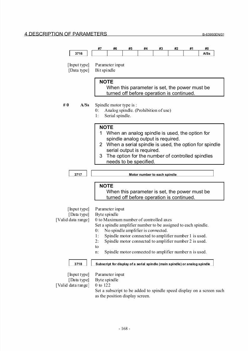
8/21/2019 30i Parameter Manual
http://slidepdf.com/reader/full/30i-parameter-manual 180/493
4.DESCRIPTION OF PARAMETERS B-63950EN/01
- 168 -
#7 #6 #5 #4 #3 #2 #1 #0
3716 A/Ss
[Input type] Parameter input
[Data type] Bit spindle
NOTEWhen this parameter is set, the power must beturned off before operation is continued.
# 0 A/Ss Spindle motor type is :
0: Analog spindle. (Prohibition of use)
1: Serial spindle.
NOTE1 When an analog spindle is used, the option for
spindle analog output is required.2 When a serial spindle is used, the option for spindle
serial output is required.3 The option for the number of controlled spindles
needs to be specified.
3717 Motor number to each spindle
NOTEWhen this parameter is set, the power must beturned off before operation is continued.
[Input type] Parameter input
[Data type] Byte spindle
[Valid data range] 0 to Maximum number of controlled axes
Set a spindle amplifier number to be assigned to each spindle.
0: No spindle amplifier is connected.
1: Spindle motor connected to amplifier number 1 is used.
2: Spindle motor connected to amplifier number 2 is used.
ton: Spindle motor connected to amplifier number n is used.
3718 Subscript for display of a serial spindle (main spindle) or analog spindle
[Input type] Parameter input
[Data type] Byte spindle
[Valid data range] 0 to 122
Set a subscript to be added to spindle speed display on a screen such
as the position display screen.
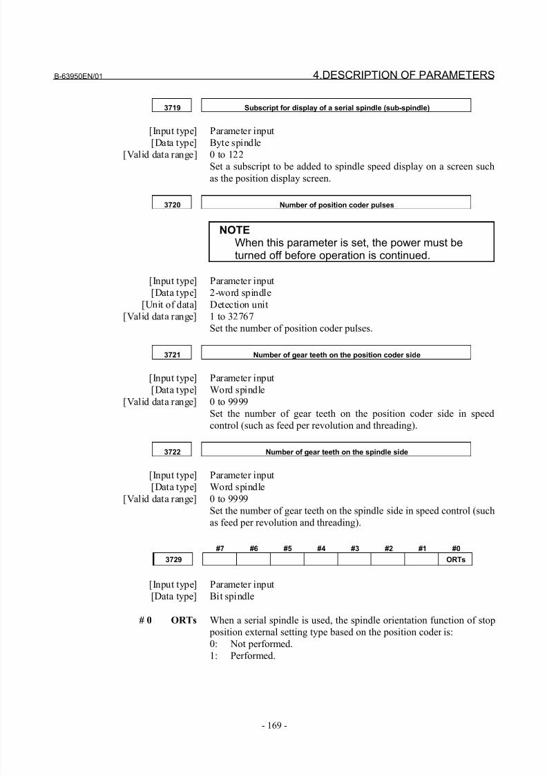
8/21/2019 30i Parameter Manual
http://slidepdf.com/reader/full/30i-parameter-manual 181/493
B-63950EN/01 4.DESCRIPTION OF PARAMETERS
- 169 -
3719 Subscript for display of a serial spindle (sub-spindle)
[Input type] Parameter input[Data type] Byte spindle
[Valid data range] 0 to 122
Set a subscript to be added to spindle speed display on a screen such
as the position display screen.
3720 Number of position coder pulses
NOTEWhen this parameter is set, the power must beturned off before operation is continued.
[Input type] Parameter input
[Data type] 2-word spindle
[Unit of data] Detection unit
[Valid data range] 1 to 32767
Set the number of position coder pulses.
3721 Number of gear teeth on the position coder side
[Input type] Parameter input
[Data type] Word spindle
[Valid data range] 0 to 9999
Set the number of gear teeth on the position coder side in speed
control (such as feed per revolution and threading).
3722 Number of gear teeth on the spindle side
[Input type] Parameter input
[Data type] Word spindle
[Valid data range] 0 to 9999
Set the number of gear teeth on the spindle side in speed control (such
as feed per revolution and threading).
#7 #6 #5 #4 #3 #2 #1 #0
3729 ORTs
[Input type] Parameter input
[Data type] Bit spindle
# 0 ORTs When a serial spindle is used, the spindle orientation function of stop
position external setting type based on the position coder is:
0: Not performed.
1: Performed.
8/21/2019 30i Parameter Manual
http://slidepdf.com/reader/full/30i-parameter-manual 182/493
4.DESCRIPTION OF PARAMETERS B-63950EN/01
- 170 -
3730 Data used for adjusting the gain of the analog output of spindle speed
[Input type] Parameter input[Data type] Word spindle
[Unit of data] 0.1%
[Valid data range] 700 to 1250
Set data used for adjusting the gain of the analog output of spindle
speed.
[Adjustment method] <1> Assign standard value 1000 to the parameter.
<2> Specify the spindle speed so that the analog output of the spindle
speed is the maximum voltage (10 V).
<3> Measure the output voltage.
<4> Assign the value obtained by the following equation to
parameter No.3730.
Setting value = (10 (V) / Measured data (V)) × 1000<5> After setting the parameter, specify the spindle speed so that the
analog output of the spindle speed is the maximum voltage.
Confirm that the output voltage is 10V.
NOTEThis parameter needs not to be set for serialspindles.
3731 Compensation value for the offset voltage of spindle speed analog output
[Input type] Parameter input
[Data type] Word spindle
[Unit of data] Velo
[Valid data range] -1024 to 1024
Set a compensation value for the offset voltage of spindle speed
analog output.
Setting = -8191 × offset voltage (V)/12.5
[Adjustment method] <1> Assign standard value 0 to the parameter.
<2> Specify the spindle speed so that the analog output of the spindle
speed is 0.
<3> Measure the output voltage.
<4> Assign the value obtained by the following equation to parameter No.3731.
Setting value = (-8191 × Offset voltage (V)) / 12.5
<5> After setting the parameter, specify the spindle speed so that the
analog output of the spindle speed is 0. Confirm that the output
voltage is 0V.
NOTEThis parameter needs not to be set for serialspindles.
8/21/2019 30i Parameter Manual
http://slidepdf.com/reader/full/30i-parameter-manual 183/493
B-63950EN/01 4.DESCRIPTION OF PARAMETERS
- 171 -
3732The spindle speed during spindle orientation or the spindle motor speed
during spindle gear shift
[Input type] Parameter input
[Data type] 2-word path
[Valid data range] 0 to 20000
Set the spindle speed during spindle orientation or the spindle motor
speed during gear shift.
When GST, #1 of parameter 3705, is set to 0, set the spindle speed
during spindle orientation in min-1
.
When GST, #1 of parameter 3705, is set to 1, set the spindle motor
speed during spindle gear shift calculated from the following formula.
For a serial spindle
Setting value =
(Spindle motor speed during spindle gear shift / Maximumspindle motor speed) × 16383
For an analog spindle
Setting value =
(Spindle motor speed during spindle gear shift / Maximum
spindle motor speed) × 4095
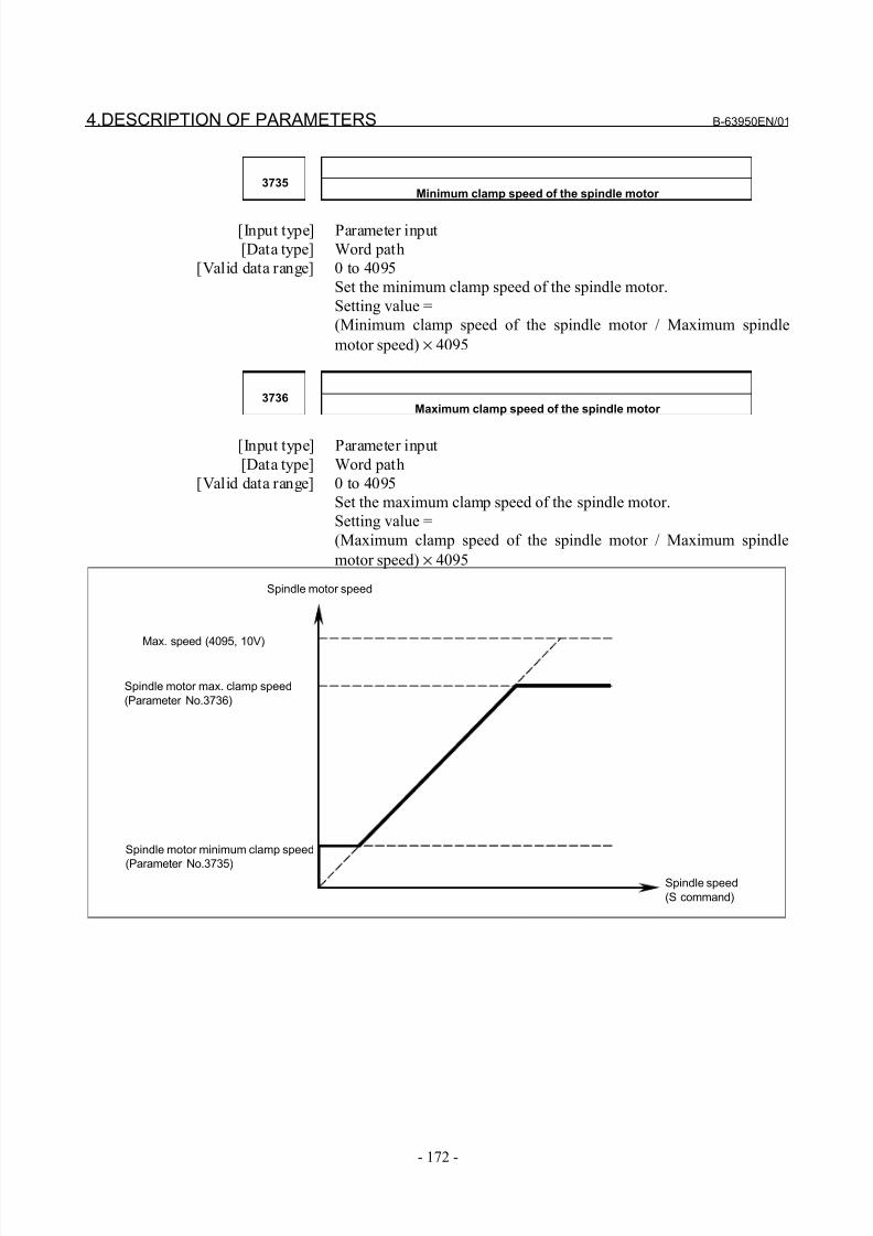
8/21/2019 30i Parameter Manual
http://slidepdf.com/reader/full/30i-parameter-manual 184/493
4.DESCRIPTION OF PARAMETERS B-63950EN/01
- 172 -
3735Minimum clamp speed of the spindle motor
[Input type] Parameter input
[Data type] Word path
[Valid data range] 0 to 4095
Set the minimum clamp speed of the spindle motor.
Setting value =
(Minimum clamp speed of the spindle motor / Maximum spindle
motor speed) × 4095
3736Maximum clamp speed of the spindle motor
[Input type] Parameter input
[Data type] Word path
[Valid data range] 0 to 4095
Set the maximum clamp speed of the spindle motor.
Setting value =
(Maximum clamp speed of the spindle motor / Maximum spindle
motor speed) × 4095
Spindle motor max. clamp speed
(Parameter No.3736)
Spindle speed
(S command)
Max. speed (4095, 10V)
Spindle motor minimum clamp speed
(Parameter No.3735)
Spindle motor speed
8/21/2019 30i Parameter Manual
http://slidepdf.com/reader/full/30i-parameter-manual 185/493
B-63950EN/01 4.DESCRIPTION OF PARAMETERS
- 173 -
3738 Spindle name 2 of each spindle
3739 Spindle name 3 of each spindle
[Input type] Parameter input
[Data type] Byte spindle
[Valid data range] 48to57,65to90
The command for a spindle is basically "S".
When all conditions below are satisfied, however, an extended
spindle name can be used. An extended spindle name consists of up to
three characters starting with "S" as the first spindle name. Thus, a
command for a spindle can be specified.
- The serial (analog) spindle function is enabled.
- The multi-spindle function is enabled.
- Bit 0 (EEA) of parameter No. 1000 is set to 1.
- Bit 3 (MPP) of parameter No. 3703 is set to 1.
- Bit 1 (ESN) of parameter No. 3798 is set to 1.
- Bit 4 (GTT) of parameter No. 3706 is set to 1. (M series only)
As spindle name 2 (No. 3738) and spindle name 3 (No. 3739), ASCII
codes from 0 to 9 and A to Z can be arbitrary set. However, before
spindle name 3 for a spindle can be valid, spindle name 2 must be set
for the spindle. Moreover, when a character from 0 to 9 is set as
spindle name 2, do not set a character from A to Z as spindle name 3.
NOTE1 When an extended spindle name is used, a
subscript (for a main spindle (parameter No. 3718))and a subscript (for a sub-spindle (parameter No.3719)) are unusable.
2 When the custom macro function is enabled, thesame extended spindle name as a reserved wordmust not be used. Such an extended spindlename is regarded as a reserved word.
3740 Time elapsed prior to checking the spindle speed arrival signal
[Input type] Parameter input
[Data type] Word path
[Unit of data] msec
[Valid data range] 0 to 32767
Set the time elapsed from the execution of the S function up to the
checking of the spindle speed arrival signal.
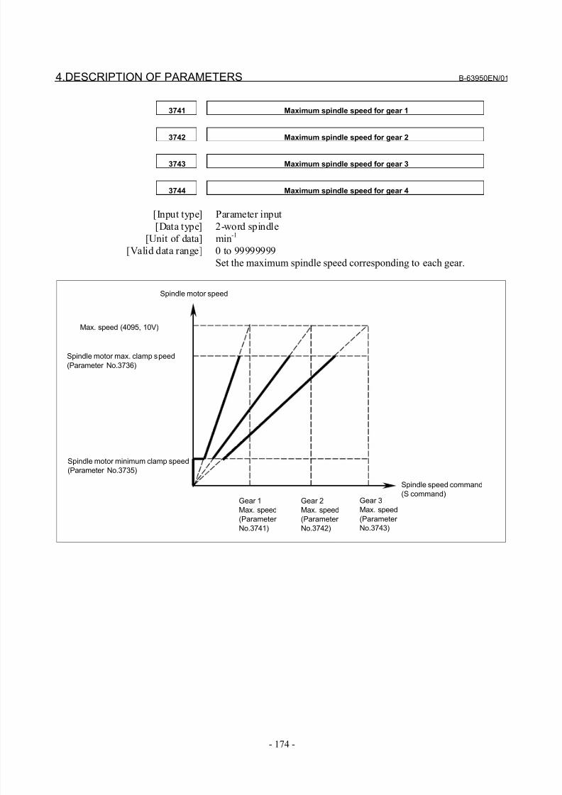
8/21/2019 30i Parameter Manual
http://slidepdf.com/reader/full/30i-parameter-manual 186/493
4.DESCRIPTION OF PARAMETERS B-63950EN/01
- 174 -
3741 Maximum spindle speed for gear 1
3742 Maximum spindle speed for gear 2
3743 Maximum spindle speed for gear 3
3744 Maximum spindle speed for gear 4
[Input type] Parameter input
[Data type] 2-word spindle
[Unit of data] min-1
[Valid data range] 0 to 99999999
Set the maximum spindle speed corresponding to each gear.
Spindle motor max. clamp speed
(Parameter No.3736)
Spindle speed command
(S command)
Max. speed (4095, 10V)
Spindle motor minimum clamp speed
(Parameter No.3735)
Spindle motor speed
Gear 1
Max. speed
(Parameter
No.3741)
Gear 2
Max. speed
(Parameter
No.3742)
Gear 3
Max. speed
(Parameter
No.3743)
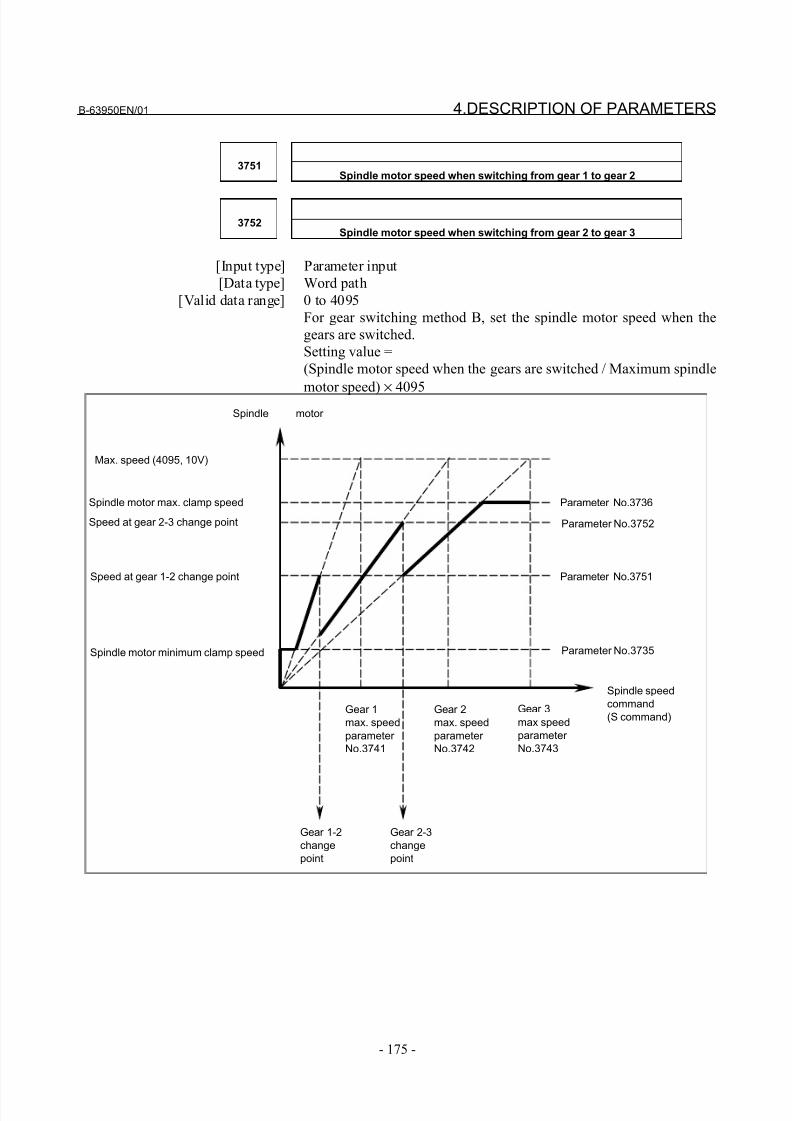
8/21/2019 30i Parameter Manual
http://slidepdf.com/reader/full/30i-parameter-manual 187/493
B-63950EN/01 4.DESCRIPTION OF PARAMETERS
- 175 -
3751Spindle motor speed when switching from gear 1 to gear 2
3752Spindle motor speed when switching from gear 2 to gear 3
[Input type] Parameter input
[Data type] Word path
[Valid data range] 0 to 4095
For gear switching method B, set the spindle motor speed when the
gears are switched.
Setting value =
(Spindle motor speed when the gears are switched / Maximum spindle
motor speed) × 4095
Spindle motor max. clamp speed
Spindle speed
command
(S command)
Max. speed (4095, 10V)
Spindle motor minimum clamp speed
Spindle motor
Gear 1-2
change
point
Gear 2-3
change
point
Gear 1
max. speed
parameter
No.3741
Gear 2
max. speed
parameter
No.3742
Gear 3
max speed
parameter
No.3743
Parameter No.3736
Parameter No.3752
Parameter No.3751
Parameter No.3735
Speed at gear 2-3 change point
Speed at gear 1-2 change point
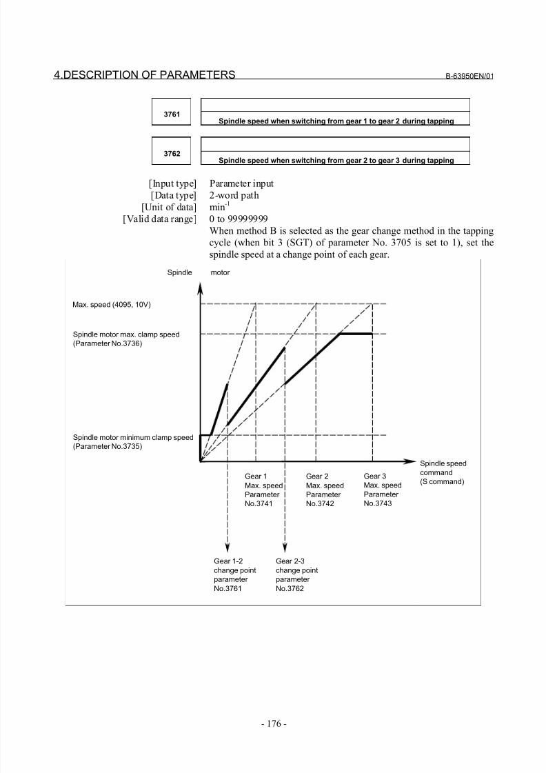
8/21/2019 30i Parameter Manual
http://slidepdf.com/reader/full/30i-parameter-manual 188/493
4.DESCRIPTION OF PARAMETERS B-63950EN/01
- 176 -
3761Spindle speed when switching from gear 1 to gear 2 during tapping
3762Spindle speed when switching from gear 2 to gear 3 during tapping
[Input type] Parameter input
[Data type] 2-word path
[Unit of data] min-1
[Valid data range] 0 to 99999999
When method B is selected as the gear change method in the tapping
cycle (when bit 3 (SGT) of parameter No. 3705 is set to 1), set the
spindle speed at a change point of each gear.
Spindle motor max. clamp speed
(Parameter No.3736)
Spindle speed
command
(S command)
Max. speed (4095, 10V)
Spindle motor minimum clamp speed
(Parameter No.3735)
Spindle motor
Gear 1-2
change point
parameter
No.3761
Gear 2-3
change point
parameter
No.3762
Gear 1
Max. speed
Parameter
No.3741
Gear 2
Max. speed
Parameter
No.3742
Gear 3
Max. speed
Parameter
No.3743
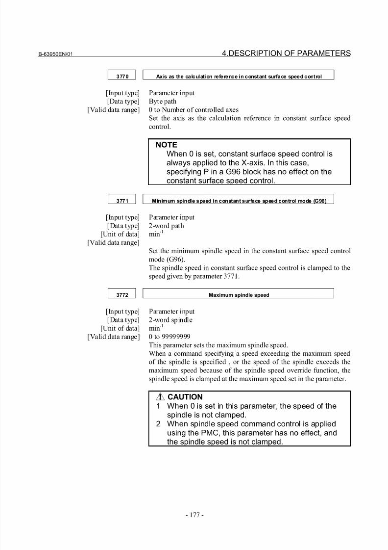
8/21/2019 30i Parameter Manual
http://slidepdf.com/reader/full/30i-parameter-manual 189/493
B-63950EN/01 4.DESCRIPTION OF PARAMETERS
- 177 -
3770 Axis as the calculation reference in constant surface speed control
[Input type] Parameter input[Data type] Byte path
[Valid data range] 0 to Number of controlled axes
Set the axis as the calculation reference in constant surface speed
control.
NOTEWhen 0 is set, constant surface speed control isalways applied to the X-axis. In this case,specifying P in a G96 block has no effect on theconstant surface speed control.
3771 Minimum spindle speed in constant surface speed control mode (G96)
[Input type] Parameter input
[Data type] 2-word path
[Unit of data] min-1
[Valid data range]
Set the minimum spindle speed in the constant surface speed control
mode (G96).
The spindle speed in constant surface speed control is clamped to the
speed given by parameter 3771.
3772 Maximum spindle speed
[Input type] Parameter input
[Data type] 2-word spindle
[Unit of data] min-1
[Valid data range] 0 to 99999999
This parameter sets the maximum spindle speed.
When a command specifying a speed exceeding the maximum speed
of the spindle is specified , or the speed of the spindle exceeds the
maximum speed because of the spindle speed override function, the
spindle speed is clamped at the maximum speed set in the parameter.
CAUTION1 When 0 is set in this parameter, the speed of the
spindle is not clamped.2 When spindle speed command control is applied
using the PMC, this parameter has no effect, andthe spindle speed is not clamped.
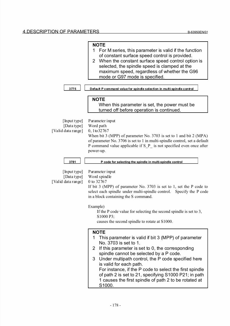
8/21/2019 30i Parameter Manual
http://slidepdf.com/reader/full/30i-parameter-manual 190/493
4.DESCRIPTION OF PARAMETERS B-63950EN/01
- 178 -
NOTE1 For M series, this parameter is valid if the function
of constant surface speed control is provided.2 When the constant surface speed control option isselected, the spindle speed is clamped at themaximum speed, regardless of whether the G96mode or G97 mode is specified.
3775 Default P command value for spindle selection in multi-spindle control
NOTEWhen this parameter is set, the power must beturned off before operation is continued.
[Input type] Parameter input
[Data type] Word path
[Valid data range] 0, 1to32767
When bit 3 (MPP) of parameter No. 3703 is set to 1 and bit 2 (MPA)
of parameter No. 3706 is set to 1 in multi-spindle control, set a default
P command value applicable if S_P_ is not specified even once after
power-up.
3781 P code for selecting the spindle in multi-spindle control
[Input type] Parameter input[Data type] Word spindle
[Valid data range] 0 to 32767
If bit 3 (MPP) of parameter No. 3703 is set to 1, set the P code to
select each spindle under multi-spindle control. Specify the P code
in a block containing the S command.
Example)
If the P code value for selecting the second spindle is set to 3,
S1000 P3;
causes the second spindle to rotate at S1000.
NOTE1 This parameter is valid if bit 3 (MPP) of parameter
No. 3703 is set to 1.2 If this parameter is set to 0, the corresponding
spindle cannot be selected by a P code.3 Under multipath control, the P code specified here
is valid for each path.For instance, if the P code to select the first spindleof path 2 is set to 21, specifying S1000 P21; in path1 causes the first spindle of path 2 to be rotated at
S1000.
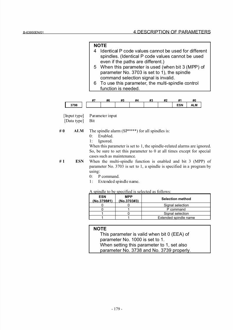
8/21/2019 30i Parameter Manual
http://slidepdf.com/reader/full/30i-parameter-manual 191/493
B-63950EN/01 4.DESCRIPTION OF PARAMETERS
- 179 -
NOTE4 Identical P code values cannot be used for different
spindles. (Identical P code values cannot be usedeven if the paths are different.)5 When this parameter is used (when bit 3 (MPP) of
parameter No. 3703 is set to 1), the spindlecommand selection signal is invalid.
6 To use this parameter, the multi-spindle controlfunction is needed.
#7 #6 #5 #4 #3 #2 #1 #0
3798 ESN ALM
[Input type] Parameter input[Data type] Bit
# 0 ALM The spindle alarm (SP****) for all spindles is:
0: Enabled.
1: Ignored.
When this parameter is set to 1, the spindle-related alarms are ignored.
So, be sure to set this parameter to 0 at all times except for special
cases such as maintenance.
# 1 ESN When the multi-spindle function is enabled and bit 3 (MPP) of
parameter No. 3703 is set to 1, a spindle is specified in a program by
using:0: P command.
1: Extended spindle name.
A spindle to be specified is selected as follows:
ESN
(No.3798#1)
MPP
(No.3703#3)Selection method
0 0 Signal selection0 1 P command1 0 Signal selection1 1 Extended spindle name
NOTEThis parameter is valid when bit 0 (EEA) of parameter No. 1000 is set to 1.When setting this parameter to 1, set alsoparameter No. 3738 and No. 3739 properly.
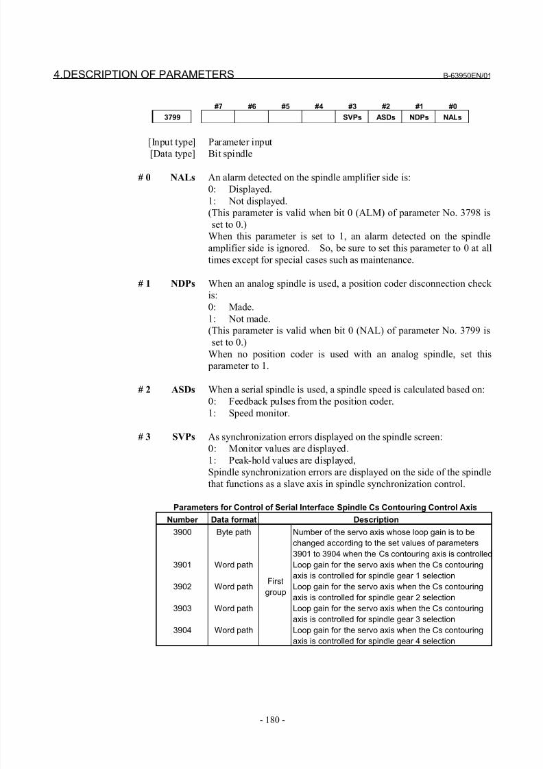
8/21/2019 30i Parameter Manual
http://slidepdf.com/reader/full/30i-parameter-manual 192/493
4.DESCRIPTION OF PARAMETERS B-63950EN/01
- 180 -
#7 #6 #5 #4 #3 #2 #1 #0
3799 SVPs ASDs NDPs NALs
[Input type] Parameter input
[Data type] Bit spindle
# 0 NALs An alarm detected on the spindle amplifier side is:
0: Displayed.
1: Not displayed.
(This parameter is valid when bit 0 (ALM) of parameter No. 3798 is
set to 0.)
When this parameter is set to 1, an alarm detected on the spindle
amplifier side is ignored. So, be sure to set this parameter to 0 at all
times except for special cases such as maintenance.
# 1 NDPs When an analog spindle is used, a position coder disconnection check
is:
0: Made.
1: Not made.
(This parameter is valid when bit 0 (NAL) of parameter No. 3799 is
set to 0.)
When no position coder is used with an analog spindle, set this
parameter to 1.
# 2 ASDs When a serial spindle is used, a spindle speed is calculated based on:
0: Feedback pulses from the position coder.1: Speed monitor.
# 3 SVPs As synchronization errors displayed on the spindle screen:
0: Monitor values are displayed.
1: Peak-hold values are displayed,
Spindle synchronization errors are displayed on the side of the spindle
that functions as a slave axis in spindle synchronization control.
Parameters for Control of Serial Interface Spindle Cs Contouring Control Axis
Number Data format Description
3900
3901
3902
3903
3904
Byte path
Word path
Word path
Word path
Word path
First
group
Number of the servo axis whose loop gain is to be
changed according to the set values of parameters
3901 to 3904 when the Cs contouring axis is controlled
Loop gain for the servo axis when the Cs contouring
axis is controlled for spindle gear 1 selection
Loop gain for the servo axis when the Cs contouring
axis is controlled for spindle gear 2 selection
Loop gain for the servo axis when the Cs contouring
axis is controlled for spindle gear 3 selection
Loop gain for the servo axis when the Cs contouring
axis is controlled for spindle gear 4 selection
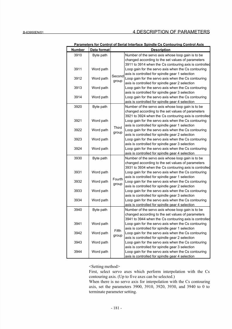
8/21/2019 30i Parameter Manual
http://slidepdf.com/reader/full/30i-parameter-manual 193/493
B-63950EN/01 4.DESCRIPTION OF PARAMETERS
- 181 -
Parameters for Control of Serial Interface Spindle Cs Contouring Control Axis
Number Data format Description
3910
3911
3912
3913
3914
Byte path
Word path
Word path
Word path
Word path
Second
group
Number of the servo axis whose loop gain is to be
changed according to the set values of parameters
3911 to 3914 when the Cs contouring axis is controlled
Loop gain for the servo axis when the Cs contouring
axis is controlled for spindle gear 1 selection
Loop gain for the servo axis when the Cs contouring
axis is controlled for spindle gear 2 selection
Loop gain for the servo axis when the Cs contouring
axis is controlled for spindle gear 3 selection
Loop gain for the servo axis when the Cs contouring
axis is controlled for spindle gear 4 selection
3920
3921
3922
3923
3924
Byte path
Word path
Word path
Word path
Word path
Third
group
Number of the servo axis whose loop gain is to be
changed according to the set values of parameters
3921 to 3924 when the Cs contouring axis is controlledLoop gain for the servo axis when the Cs contouring
axis is controlled for spindle gear 1 selection
Loop gain for the servo axis when the Cs contouring
axis is controlled for spindle gear 2 selection
Loop gain for the servo axis when the Cs contouring
axis is controlled for spindle gear 3 selection
Loop gain for the servo axis when the Cs contouring
axis is controlled for spindle gear 4 selection
3930
3931
3932
3933
3934
Byte path
Word path
Word path
Word path
Word path
Fourth
group
Number of the servo axis whose loop gain is to be
changed according to the set values of parameters
3931 to 3934 when the Cs contouring axis is controlled
Loop gain for the servo axis when the Cs contouringaxis is controlled for spindle gear 1 selection
Loop gain for the servo axis when the Cs contouring
axis is controlled for spindle gear 2 selection
Loop gain for the servo axis when the Cs contouring
axis is controlled for spindle gear 3 selection
Loop gain for the servo axis when the Cs contouring
axis is controlled for spindle gear 4 selection
3940
3941
3942
3943
3944
Byte path
Word path
Word path
Word path
Word path
Fifthgroup
Number of the servo axis whose loop gain is to be
changed according to the set values of parameters
3941 to 3944 when the Cs contouring axis is controlled
Loop gain for the servo axis when the Cs contouring
axis is controlled for spindle gear 1 selection
Loop gain for the servo axis when the Cs contouring
axis is controlled for spindle gear 2 selection
Loop gain for the servo axis when the Cs contouring
axis is controlled for spindle gear 3 selection
Loop gain for the servo axis when the Cs contouring
axis is controlled for spindle gear 4 selection
<Setting method>
First, select servo axes which perform interpolation with the Cs
contouring axis. (Up to five axes can be selected.)
When there is no servo axis for interpolation with the Cs contouring
axis, set the parameters 3900, 3910, 3920, 3930, and 3940 to 0 toterminate parameter setting.

8/21/2019 30i Parameter Manual
http://slidepdf.com/reader/full/30i-parameter-manual 194/493
4.DESCRIPTION OF PARAMETERS B-63950EN/01
- 182 -
When there are servo axes for interpolation with the Cs contouring
axis, the parameters must be set according to the procedure below for
each axis.
(1) Set the number of a servo axis (1 to maximum number of
controlled axes) for interpolation with the Cs contouring axis in
parameters 39n0 (n = 0, 1, 2, 3, and 4).
(2) Set loop gain values of the servo axis specified in (1) above
which is used when the Cs contouring axis is controlled in
parameters 39n1, 39n2, 39n3, and 39n4. (There are four stages
for main gears used.)
(3) When the number of specified servo axes is less than 5, set the
remaining parameters (39n0) to 0 to terminate parameter setting.
When the number of a Cs contouring axis is set to parameter 39n0,
the parameter is assumed to be set to 0.
NOTE1 In general, it is difficult to set a high loop gain for a
spindle motor axis when compared with a servoaxis. These parameters are provided so that, bychanging the loop gain of a servo axis that requiresinterpolation with the Cs contour axis, interpolationcontrol can be exercised correctly between the Csaxis and servo axis while the spindle exercises Cscontour control.
2 The loop gain of the servo axis is changed using
the parameter settings made for a spindle gear selected at the time of conversion from the spindlemode to the Cs contour control mode.In normal use, it is unlikely that the gear of thespindle is switched during Cs contour control.However, note that if the gear of the spindle ischanged during Cs contour control, the loop gain of the servo axis is not changed.
3 Even when multiple Cs axes are used with one path(bit 7 (CSS) of parameter No. 3704 = 1), theseparameters are shared.
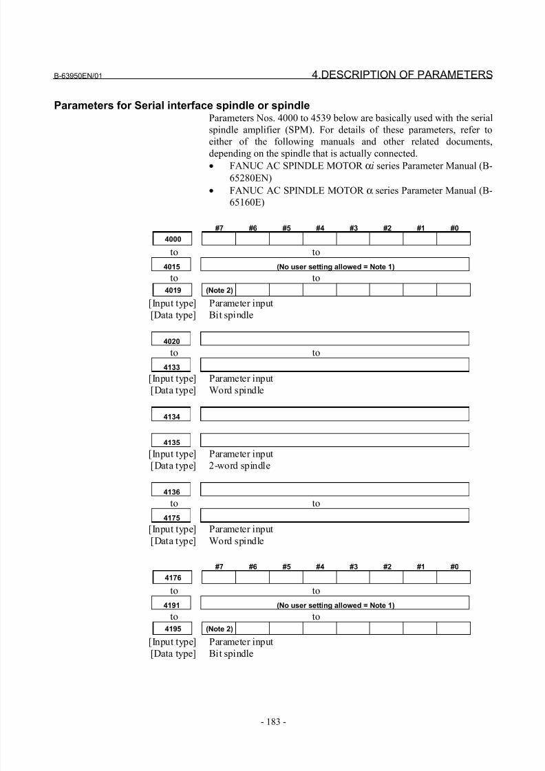
8/21/2019 30i Parameter Manual
http://slidepdf.com/reader/full/30i-parameter-manual 195/493
B-63950EN/01 4.DESCRIPTION OF PARAMETERS
- 183 -
Parameters for Serial interface spindle or spindleParameters Nos. 4000 to 4539 below are basically used with the serial
spindle amplifier (SPM). For details of these parameters, refer toeither of the following manuals and other related documents,
depending on the spindle that is actually connected.
• FANUC AC SPINDLE MOTOR αi series Parameter Manual (B-
65280EN)
• FANUC AC SPINDLE MOTOR α series Parameter Manual (B-
65160E)
#7 #6 #5 #4 #3 #2 #1 #0
4000
to to
4015 (No user setting allowed = Note 1)to to
4019 (Note 2)
[Input type] Parameter input
[Data type] Bit spindle
4020
to to
4133
[Input type] Parameter input
[Data type] Word spindle
4134
4135
[Input type] Parameter input
[Data type] 2-word spindle
4136
to to
4175
[Input type] Parameter input
[Data type] Word spindle
#7 #6 #5 #4 #3 #2 #1 #0
4176
to to
4191 (No user setting allowed = Note 1)
to to
4195 (Note 2)
[Input type] Parameter input
[Data type] Bit spindle

8/21/2019 30i Parameter Manual
http://slidepdf.com/reader/full/30i-parameter-manual 196/493
4.DESCRIPTION OF PARAMETERS B-63950EN/01
- 184 -
4196
to to
4309[Input type] Parameter input
[Data type] Word spindle
4310
4311
[Input type] Parameter input
[Data type] 2-word spindle
4312
to to4351
[Input type] Parameter input
[Data type] Word spindle
#7 #6 #5 #4 #3 #2 #1 #0
4352
4353
[Input type] Parameter input
[Data type] Bit spindle
4354
to to
4371 (No user setting allowed = Note 1)
4372
[Input type] Parameter input
[Data type] Word spindle
#7 #6 #5 #4 #3 #2 #1 #0
4373
4374
[Input type] Parameter input
[Data type] Bit spindle
4375
to to
4393
[Input type] Parameter input
[Data type] Word spindle
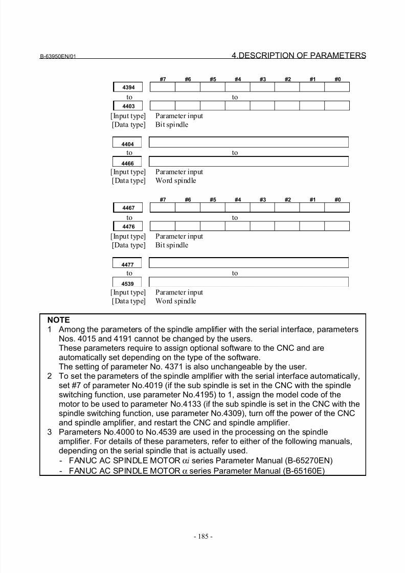
8/21/2019 30i Parameter Manual
http://slidepdf.com/reader/full/30i-parameter-manual 197/493
B-63950EN/01 4.DESCRIPTION OF PARAMETERS
- 185 -
#7 #6 #5 #4 #3 #2 #1 #0
4394
to to4403
[Input type] Parameter input
[Data type] Bit spindle
4404
to to
4466
[Input type] Parameter input
[Data type] Word spindle
#7 #6 #5 #4 #3 #2 #1 #04467
to to
4476
[Input type] Parameter input
[Data type] Bit spindle
4477
to to
4539
[Input type] Parameter input
[Data type] Word spindle
NOTE1 Among the parameters of the spindle amplifier with the serial interface, parameters
Nos. 4015 and 4191 cannot be changed by the users.These parameters require to assign optional software to the CNC and areautomatically set depending on the type of the software.The setting of parameter No. 4371 is also unchangeable by the user.
2 To set the parameters of the spindle amplifier with the serial interface automatically,set #7 of parameter No.4019 (if the sub spindle is set in the CNC with the spindleswitching function, use parameter No.4195) to 1, assign the model code of the
motor to be used to parameter No.4133 (if the sub spindle is set in the CNC with thespindle switching function, use parameter No.4309), turn off the power of the CNCand spindle amplifier, and restart the CNC and spindle amplifier.
3 Parameters No.4000 to No.4539 are used in the processing on the spindleamplifier. For details of these parameters, refer to either of the following manuals,depending on the serial spindle that is actually used.
- FANUC AC SPINDLE MOTOR αi series Parameter Manual (B-65270EN)
- FANUC AC SPINDLE MOTOR α series Parameter Manual (B-65160E)
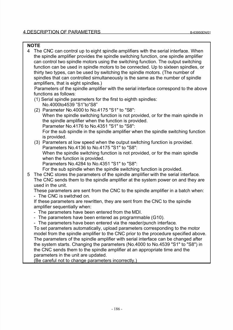
8/21/2019 30i Parameter Manual
http://slidepdf.com/reader/full/30i-parameter-manual 198/493
4.DESCRIPTION OF PARAMETERS B-63950EN/01
- 186 -
NOTE4 The CNC can control up to eight spindle amplifiers with the serial interface. When
the spindle amplifier provides the spindle switching function, one spindle amplifier can control two spindle motors using the switching function. The output switchingfunction can be used in spindle motors to be connected. Up to sixteen spindles, or thirty two types, can be used by switching the spindle motors. (The number of spindles that can controlled simultaneously is the same as the number of spindleamplifiers, that is eight spindles.)
Parameters of the spindle amplifier with the serial interface correspond to the abovefunctions as follows:(1) Serial spindle parameters for the first to eighth spindles:
No.4000to4539 ”S1”to“S8”(2) Parameter No.4000 to No.4175 "S1" to "S8":
When the spindle switching function is not provided, or for the main spindle inthe spindle amplifier when the function is provided.Parameter No.4176 to No.4351 "S1" to "S8":For the sub spindle in the spindle amplifier when the spindle switching functionis provided.
(3) Parameters at low speed when the output switching function is provided.Parameters No.4136 to No.4175 "S1" to "S8":When the spindle switching function is not provided, or for the main spindlewhen the function is provided.Parameters No.4284 to No.4351 "S1" to "S8":For the sub spindle when the spindle switching function is provided.
5 The CNC stores the parameters of the spindle amplifier with the serial interface.The CNC sends them to the spindle amplifier at the system power on and they areused in the unit.These parameters are sent from the CNC to the spindle amplifier in a batch when:- The CNC is switched on.
If these parameters are rewritten, they are sent from the CNC to the spindleamplifier sequentially when:- The parameters have been entered from the MDI.- The parameters have been entered as programmable (G10).- The parameters have been entered via the reader/punch interface.To set parameters automatically, upload parameters corresponding to the motor model from the spindle amplifier to the CNC prior to the procedure specified above.The parameters of the spindle amplifier with serial interface can be changed after the system starts. Changing the parameters (No.4000 to No.4539 "S1" to "S8") inthe CNC sends them to the spindle amplifier at an appropriate time and theparameters in the unit are updated.(Be careful not to change parameters incorrectly.)
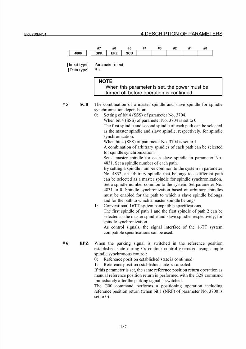
8/21/2019 30i Parameter Manual
http://slidepdf.com/reader/full/30i-parameter-manual 199/493
B-63950EN/01 4.DESCRIPTION OF PARAMETERS
- 187 -
#7 #6 #5 #4 #3 #2 #1 #0
4800 SPK EPZ SCB
[Input type] Parameter input
[Data type] Bit
NOTEWhen this parameter is set, the power must beturned off before operation is continued.
# 5 SCB The combination of a master spindle and slave spindle for spindle
synchronization depends on:
0: Setting of bit 4 (SSS) of parameter No. 3704.
When bit 4 (SSS) of parameter No. 3704 is set to 0The first spindle and second spindle of each path can be selected
as the master spindle and slave spindle, respectively, for spindle
synchronization.
When bit 4 (SSS) of parameter No. 3704 is set to 1
A combination of arbitrary spindles of each path can be selected
for spindle synchronization.
Set a master spindle for each slave spindle in parameter No.
4831. Set a spindle number of each path.
By setting a spindle number common to the system in parameter
No. 4832, an arbitrary spindle that belongs to a different path
can be selected as a master spindle for spindle synchronization.
Set a spindle number common to the system. Set parameter No.4831 to 0. Spindle synchronization based on arbitrary spindles
must be enabled for the path to which a slave spindle belongs
and for the path to which a master spindle belongs.
1: Conventional 16TT system compatible specifications.
The first spindle of path 1 and the first spindle of path 2 can be
selected as the master spindle and slave spindle, respectively, for
spindle synchronization.
As control signals, the signal interface of the 16TT system
compatible specifications can be used.
# 6 EPZ When the parking signal is switched in the reference positionestablished state during Cs contour control exercised using simple
spindle synchronous control:
0: Reference position established state is continued.
1: Reference position established state is canceled.
If this parameter is set, the same reference position return operation as
manual reference position return is performed with the G28 command
immediately after the parking signal is switched.
The G00 command performs a positioning operation including
reference position return (when bit 1 (NRF) of parameter No. 3700 is
set to 0).
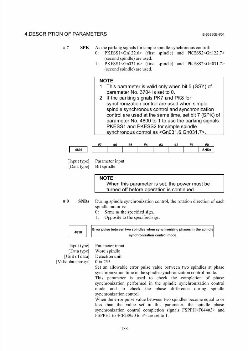
8/21/2019 30i Parameter Manual
http://slidepdf.com/reader/full/30i-parameter-manual 200/493
4.DESCRIPTION OF PARAMETERS B-63950EN/01
- 188 -
# 7 SPK As the parking signals for simple spindle synchronous control:
0: PKESS1<Gn122.6> (first spindle) and PKESS2<Gn122.7>
(second spindle) are used.
1: PKESS1<Gn031.6> (first spindle) and PKESS2<Gn031.7>
(second spindle) are used.
NOTE1 This parameter is valid only when bit 5 (SSY) of
parameter No. 3704 is set to 0.2 If the parking signals PK7 and PK8 for
synchronization control are used when simplespindle synchronous control and synchronizationcontrol are used at the same time, set bit 7 (SPK) of
parameter No. 4800 to 1 to use the parking signalsPKESS1 and PKESS2 for simple spindlesynchronous control as <Gn031.6,Gn031.7>.
#7 #6 #5 #4 #3 #2 #1 #0
4801 SNDs
[Input type] Parameter input
[Data type] Bit spindle
NOTE
When this parameter is set, the power must beturned off before operation is continued.
# 0 SNDs During spindle synchronization control, the rotation direction of each
spindle motor is:
0: Same as the specified sign.
1: Opposite to the specified sign.
4810Error pulse between two spindles when synchronizing phases in the spindle
synchronization control mode
[Input type] Parameter input[Data type] Word spindle
[Unit of data] Detection unit
[Valid data range] 0 to 255
Set an allowable error pulse value between two spindles at phase
synchronization time in the spindle synchronization control mode.
This parameter is used to check the completion of phase
synchronization performed in the spindle synchronization control
mode and to check the phase difference during spindle
synchronization control.
When the error pulse value between two spindles become equal to or
less than the value set in this parameter, the spindle phase
synchronization control completion signals FSPPH<F044#3> and
FSPPH1 to 4<F289#0 to 3> are set to 1.
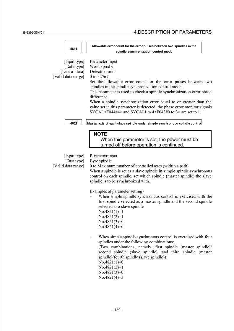
8/21/2019 30i Parameter Manual
http://slidepdf.com/reader/full/30i-parameter-manual 201/493
B-63950EN/01 4.DESCRIPTION OF PARAMETERS
- 189 -
4811Allowable error count for the error pulses between two spindles in the
spindle synchronization control mode
[Input type] Parameter input
[Data type] Word spindle
[Unit of data] Detection unit
[Valid data range] 0 to 32767
Set the allowable error count for the error pulses between two
spindles in the spindle synchronization control mode.
This parameter is used to check a spindle synchronization error phase
difference.
When a spindle synchronization error equal to or greater than the
value set in this parameter is detected, the phase error monitor signals
SYCAL<F044#4> and SYCAL1 to 4<F043#0 to 3> are set to 1.
4821 Master axis of each slave spindle under simple synchronous spindle control
NOTEWhen this parameter is set, the power must beturned off before operation is continued.
[Input type] Parameter input
[Data type] Byte spindle
[Valid data range] 0 to Maximum number of controlled axes (within a path)
When a spindle is set as a slave spindle in simple spindle synchronous
control on each spindle, set which spindle (master spindle) the slave
spindle is to be synchronized with.
Examples of parameter setting)
- When simple spindle synchronous control is exercised with the
first spindle selected as a master spindle and the second spindle
selected as a slave spindle
No.4821(1)=1
No.4821(2)=1
No.4821(3)=0
No.4821(4)=0
- When simple spindle synchronous control is exercised with four
spindles under the following combinations:
(Two combinations, namely, first spindle (master spindle)/
second spindle (slave spindle), and third spindle (master
spindle)/fourth spindle (slave spindle))
No.4821(1)=0
No.4821(2)=1
No.4821(3)=0
No.4821(4)=3
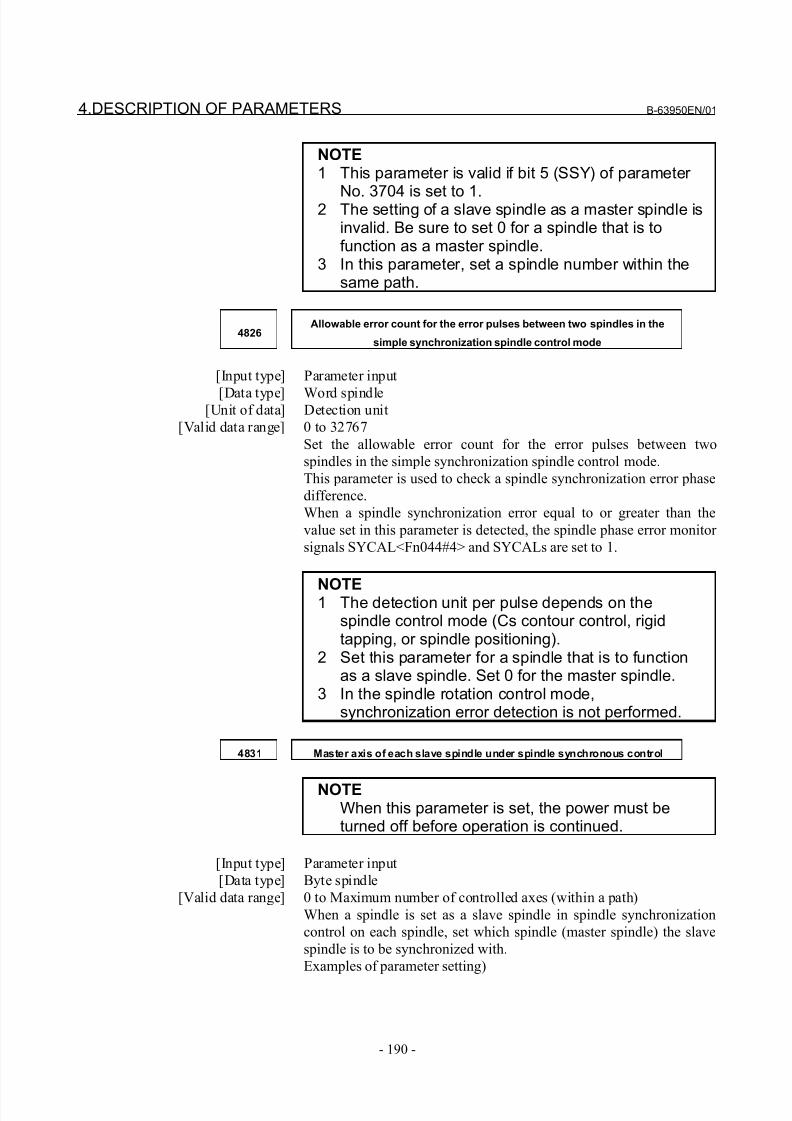
8/21/2019 30i Parameter Manual
http://slidepdf.com/reader/full/30i-parameter-manual 202/493
4.DESCRIPTION OF PARAMETERS B-63950EN/01
- 190 -
NOTE1 This parameter is valid if bit 5 (SSY) of parameter
No. 3704 is set to 1.2 The setting of a slave spindle as a master spindle isinvalid. Be sure to set 0 for a spindle that is tofunction as a master spindle.
3 In this parameter, set a spindle number within thesame path.
4826Allowable error count for the error pulses between two spindles in the
simple synchronization spindle control mode
[Input type] Parameter input
[Data type] Word spindle[Unit of data] Detection unit
[Valid data range] 0 to 32767
Set the allowable error count for the error pulses between two
spindles in the simple synchronization spindle control mode.
This parameter is used to check a spindle synchronization error phase
difference.
When a spindle synchronization error equal to or greater than the
value set in this parameter is detected, the spindle phase error monitor
signals SYCAL<Fn044#4> and SYCALs are set to 1.
NOTE1 The detection unit per pulse depends on thespindle control mode (Cs contour control, rigidtapping, or spindle positioning).
2 Set this parameter for a spindle that is to functionas a slave spindle. Set 0 for the master spindle.
3 In the spindle rotation control mode,synchronization error detection is not performed.
4831 Master axis of each slave spindle under spindle synchronous control
NOTEWhen this parameter is set, the power must beturned off before operation is continued.
[Input type] Parameter input
[Data type] Byte spindle
[Valid data range] 0 to Maximum number of controlled axes (within a path)
When a spindle is set as a slave spindle in spindle synchronization
control on each spindle, set which spindle (master spindle) the slave
spindle is to be synchronized with.
Examples of parameter setting)
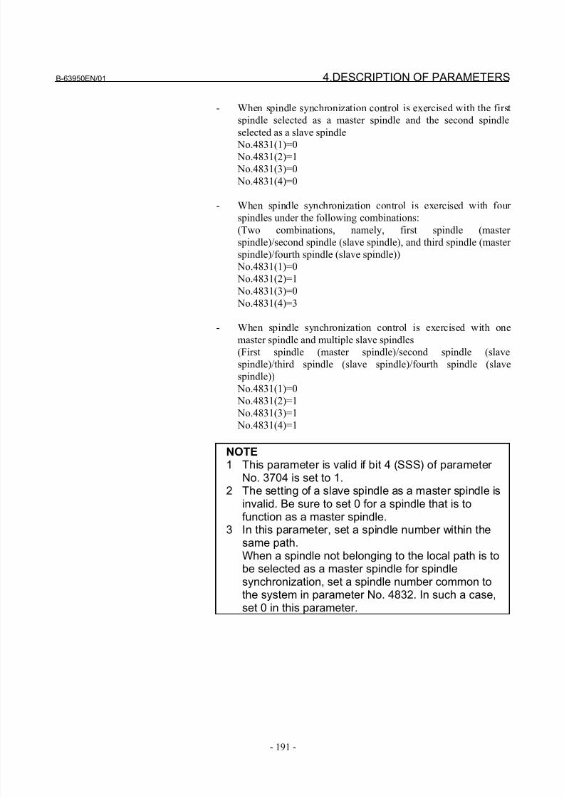
8/21/2019 30i Parameter Manual
http://slidepdf.com/reader/full/30i-parameter-manual 203/493
B-63950EN/01 4.DESCRIPTION OF PARAMETERS
- 191 -
- When spindle synchronization control is exercised with the first
spindle selected as a master spindle and the second spindle
selected as a slave spindle
No.4831(1)=0
No.4831(2)=1
No.4831(3)=0
No.4831(4)=0
- When spindle synchronization control is exercised with four
spindles under the following combinations:
(Two combinations, namely, first spindle (master
spindle)/second spindle (slave spindle), and third spindle (master
spindle)/fourth spindle (slave spindle))
No.4831(1)=0
No.4831(2)=1 No.4831(3)=0
No.4831(4)=3
- When spindle synchronization control is exercised with one
master spindle and multiple slave spindles
(First spindle (master spindle)/second spindle (slave
spindle)/third spindle (slave spindle)/fourth spindle (slave
spindle))
No.4831(1)=0
No.4831(2)=1
No.4831(3)=1
No.4831(4)=1
NOTE1 This parameter is valid if bit 4 (SSS) of parameter
No. 3704 is set to 1.2 The setting of a slave spindle as a master spindle is
invalid. Be sure to set 0 for a spindle that is tofunction as a master spindle.
3 In this parameter, set a spindle number within thesame path.
When a spindle not belonging to the local path is tobe selected as a master spindle for spindlesynchronization, set a spindle number common tothe system in parameter No. 4832. In such a case,set 0 in this parameter.
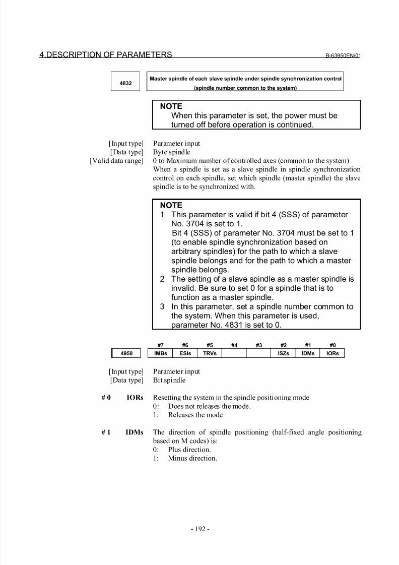
8/21/2019 30i Parameter Manual
http://slidepdf.com/reader/full/30i-parameter-manual 204/493
4.DESCRIPTION OF PARAMETERS B-63950EN/01
- 192 -
4832Master spindle of each slave spindle under spindle synchronization control
(spindle number common to the system)
NOTEWhen this parameter is set, the power must beturned off before operation is continued.
[Input type] Parameter input
[Data type] Byte spindle
[Valid data range] 0 to Maximum number of controlled axes (common to the system)
When a spindle is set as a slave spindle in spindle synchronization
control on each spindle, set which spindle (master spindle) the slave
spindle is to be synchronized with.
NOTE1 This parameter is valid if bit 4 (SSS) of parameter
No. 3704 is set to 1. Bit 4 (SSS) of parameter No. 3704 must be set to 1
(to enable spindle synchronization based onarbitrary spindles) for the path to which a slavespindle belongs and for the path to which a master spindle belongs.
2 The setting of a slave spindle as a master spindle isinvalid. Be sure to set 0 for a spindle that is to
function as a master spindle.3 In this parameter, set a spindle number common to
the system. When this parameter is used,parameter No. 4831 is set to 0.
#7 #6 #5 #4 #3 #2 #1 #0
4950 IMBs ESIs TRVs ISZs IDMs IORs
[Input type] Parameter input
[Data type] Bit spindle
# 0 IORs Resetting the system in the spindle positioning mode0: Does not releases the mode.
1: Releases the mode
# 1 IDMs The direction of spindle positioning (half-fixed angle positioning
based on M codes) is:
0: Plus direction.
1: Minus direction.
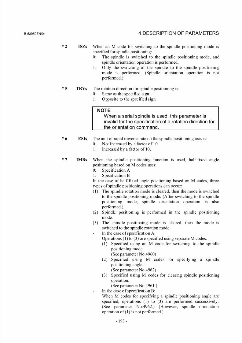
8/21/2019 30i Parameter Manual
http://slidepdf.com/reader/full/30i-parameter-manual 205/493
B-63950EN/01 4.DESCRIPTION OF PARAMETERS
- 193 -
# 2 ISZs When an M code for switching to the spindle positioning mode is
specified for spindle positioning:
0: The spindle is switched to the spindle positioning mode, and
spindle orientation operation is performed.
1: Only the switching of the spindle to the spindle positioning
mode is performed. (Spindle orientation operation is not
performed.)
# 5 TRVs The rotation direction for spindle positioning is:
0: Same as the specified sign.
1: Opposite to the specified sign.
NOTEWhen a serial spindle is used, this parameter is
invalid for the specification of a rotation direction for the orientation command.
# 6 ESIs The unit of rapid traverse rate on the spindle positioning axis is:
0: Not increased by a factor of 10.
1: Increased by a factor of 10.
# 7 IMBs When the spindle positioning function is used, half-fixed angle
positioning based on M codes uses:
0: Specification A
1: Specification B
In the case of half-fixed angle positioning based on M codes, threetypes of spindle positioning operations can occur:
(1) The spindle rotation mode is cleared, then the mode is switched
to the spindle positioning mode. (After switching to the spindle
positioning mode, spindle orientation operation is also
performed.)
(2) Spindle positioning is performed in the spindle positioning
mode.
(3) The spindle positioning mode is cleared, then the mode is
switched to the spindle rotation mode.
- In the case of specification A:
Operations (1) to (3) are specified using separate M codes.(1) Specified using an M code for switching to the spindle
positioning mode.
(See parameter No.4960)
(2) Specified using M codes for specifying a spindle
positioning angle.
(See parameter No.4962)
(3) Specified using M codes for clearing spindle positioning
operation.
(See parameter No.4961.)
- In the case of specification B:
When M codes for specifying a spindle positioning angle are
specified, operations (1) to (3) are performed successively.(See parameter No.4962.) (However, spindle orientation
operation of (1) is not performed.)
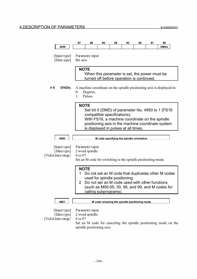
8/21/2019 30i Parameter Manual
http://slidepdf.com/reader/full/30i-parameter-manual 206/493
4.DESCRIPTION OF PARAMETERS B-63950EN/01
- 194 -
#7 #6 #5 #4 #3 #2 #1 #0
4959 DMDx
[Input type] Parameter input
[Data type] Bit axis
NOTEWhen this parameter is set, the power must beturned off before operation is continued.
# 0 DMDx A machine coordinate on the spindle positioning axis is displayed in:
0: Degrees.
1: Pulses.
NOTESet bit 0 (DMD) of parameter No. 4950 to 1 (FS16compatible specifications).With FS16, a machine coordinate on the spindlepositioning axis in the machine coordinate systemis displayed in pulses at all times.
4960 M code specifying the spindle orientation
[Input type] Parameter input[Data type] 2-word spindle
[Valid data range] 6 to 97
Set an M code for switching to the spindle positioning mode.
NOTE1 Do not set an M code that duplicates other M codes
used for spindle positioning.2 Do not set an M code used with other functions
(such as M00-05, 30, 98, and 99, and M codes for calling subprograms).
4961 M code releasing the spindle positioning mode
[Input type] Parameter input
[Data type] 2-word spindle
[Valid data range] 6 to 97
Set an M code for canceling the spindle positioning mode on the
spindle positioning axis.
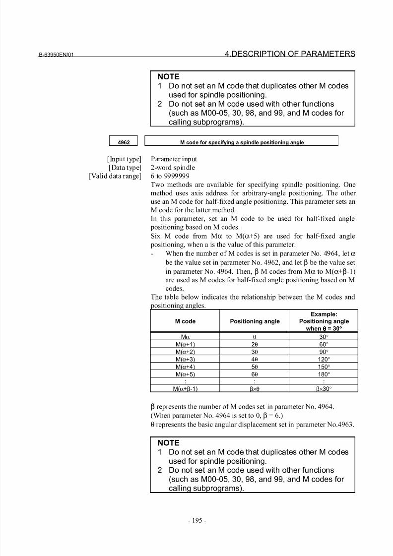
8/21/2019 30i Parameter Manual
http://slidepdf.com/reader/full/30i-parameter-manual 207/493
B-63950EN/01 4.DESCRIPTION OF PARAMETERS
- 195 -
NOTE1 Do not set an M code that duplicates other M codes
used for spindle positioning.2 Do not set an M code used with other functions(such as M00-05, 30, 98, and 99, and M codes for calling subprograms).
4962 M code for specifying a spindle positioning angle
[Input type] Parameter input
[Data type] 2-word spindle
[Valid data range] 6 to 9999999
Two methods are available for specifying spindle positioning. One
method uses axis address for arbitrary-angle positioning. The other use an M code for half-fixed angle positioning. This parameter sets an
M code for the latter method.
In this parameter, set an M code to be used for half-fixed angle
positioning based on M codes.
Six M code from Mα to M(α+5) are used for half-fixed angle
positioning, when a is the value of this parameter.
- When the number of M codes is set in parameter No. 4964, let α
be the value set in parameter No. 4962, and let β be the value set
in parameter No. 4964. Then, β M codes from Mα to M(α+β-1)
are used as M codes for half-fixed angle positioning based on M
codes.
The table below indicates the relationship between the M codes and
positioning angles.
M code Positioning angle
Example:Positioning angle
when θθθθ = 30°°°°
Mα θ 30°
M(α+1) 2θ 60°
M(α+2) 3θ 90°
M(α+3) 4θ 120°
M(α+4) 5θ 150°
M(α+5) 6θ 180°: : :
M(α+β-1) β×θ β×30°
β represents the number of M codes set in parameter No. 4964.
(When parameter No. 4964 is set to 0, β = 6.)
θ represents the basic angular displacement set in parameter No.4963.
NOTE1 Do not set an M code that duplicates other M codes
used for spindle positioning.2 Do not set an M code used with other functions
(such as M00-05, 30, 98, and 99, and M codes for
calling subprograms).
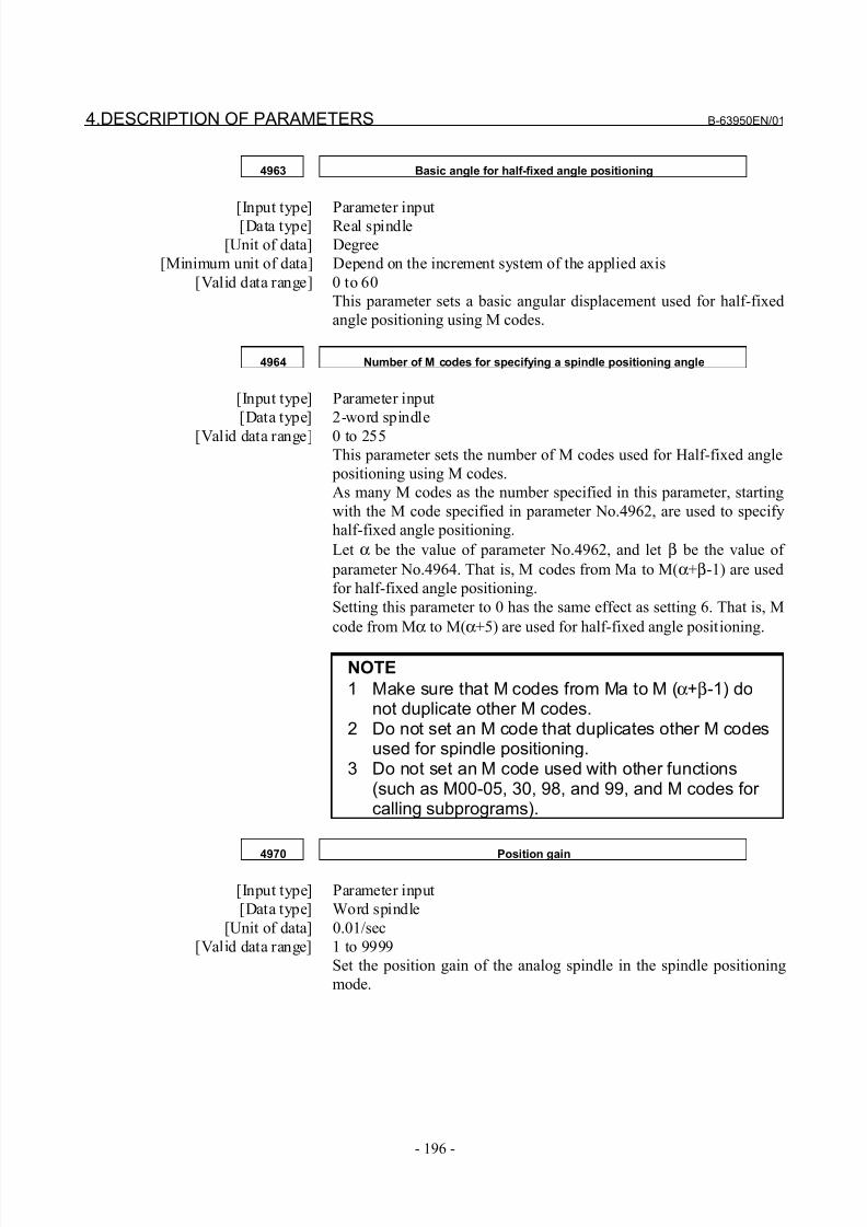
8/21/2019 30i Parameter Manual
http://slidepdf.com/reader/full/30i-parameter-manual 208/493
4.DESCRIPTION OF PARAMETERS B-63950EN/01
- 196 -
4963 Basic angle for half-fixed angle positioning
[Input type] Parameter input[Data type] Real spindle
[Unit of data] Degree
[Minimum unit of data] Depend on the increment system of the applied axis
[Valid data range] 0 to 60
This parameter sets a basic angular displacement used for half-fixed
angle positioning using M codes.
4964 Number of M codes for specifying a spindle positioning angle
[Input type] Parameter input
[Data type] 2-word spindle
[Valid data range] 0 to 255
This parameter sets the number of M codes used for Half-fixed angle
positioning using M codes.
As many M codes as the number specified in this parameter, starting
with the M code specified in parameter No.4962, are used to specify
half-fixed angle positioning.
Let α be the value of parameter No.4962, and let β be the value of
parameter No.4964. That is, M codes from Ma to M(α+β-1) are used
for half-fixed angle positioning.
Setting this parameter to 0 has the same effect as setting 6. That is, M
code from Mα to M(α+5) are used for half-fixed angle positioning.
NOTE
1 Make sure that M codes from Ma to M (α+β-1) donot duplicate other M codes.
2 Do not set an M code that duplicates other M codesused for spindle positioning.
3 Do not set an M code used with other functions(such as M00-05, 30, 98, and 99, and M codes for calling subprograms).
4970 Position gain
[Input type] Parameter input
[Data type] Word spindle
[Unit of data] 0.01/sec
[Valid data range] 1 to 9999
Set the position gain of the analog spindle in the spindle positioning
mode.
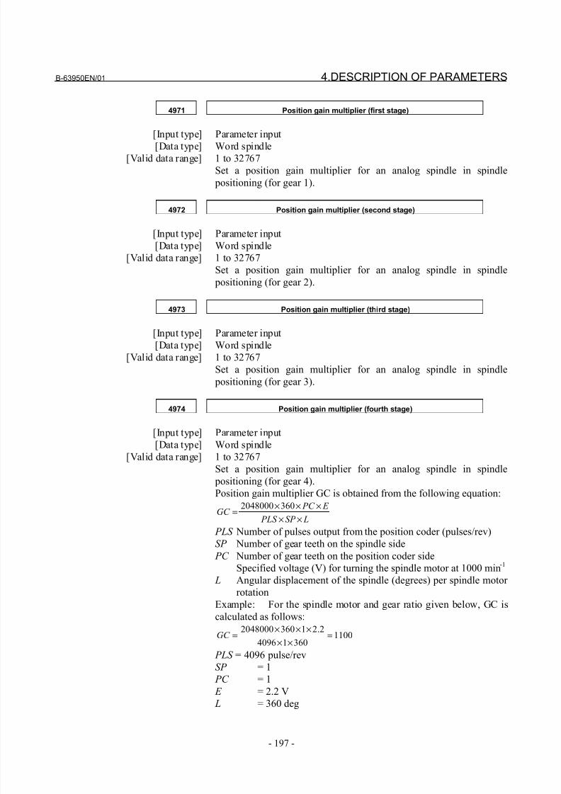
8/21/2019 30i Parameter Manual
http://slidepdf.com/reader/full/30i-parameter-manual 209/493
B-63950EN/01 4.DESCRIPTION OF PARAMETERS
- 197 -
4971 Position gain multiplier (first stage)
[Input type] Parameter input[Data type] Word spindle
[Valid data range] 1 to 32767
Set a position gain multiplier for an analog spindle in spindle
positioning (for gear 1).
4972 Position gain multiplier (second stage)
[Input type] Parameter input
[Data type] Word spindle
[Valid data range] 1 to 32767
Set a position gain multiplier for an analog spindle in spindle
positioning (for gear 2).
4973 Position gain multiplier (third stage)
[Input type] Parameter input
[Data type] Word spindle
[Valid data range] 1 to 32767
Set a position gain multiplier for an analog spindle in spindle
positioning (for gear 3).
4974 Position gain multiplier (fourth stage)
[Input type] Parameter input
[Data type] Word spindle
[Valid data range] 1 to 32767
Set a position gain multiplier for an analog spindle in spindle
positioning (for gear 4).
Position gain multiplier GC is obtained from the following equation:
LSP PLS
E PC GC
××
×××=
3602048000
PLS Number of pulses output from the position coder (pulses/rev)
SP Number of gear teeth on the spindle side
PC Number of gear teeth on the position coder sideSpecified voltage (V) for turning the spindle motor at 1000 min
-1
L Angular displacement of the spindle (degrees) per spindle motor
rotation
Example: For the spindle motor and gear ratio given below, GC is
calculated as follows:
110036014096
2.213602048000=
××
×××=GC
PLS = 4096 pulse/rev
SP = 1
PC = 1
E = 2.2 V L = 360 deg
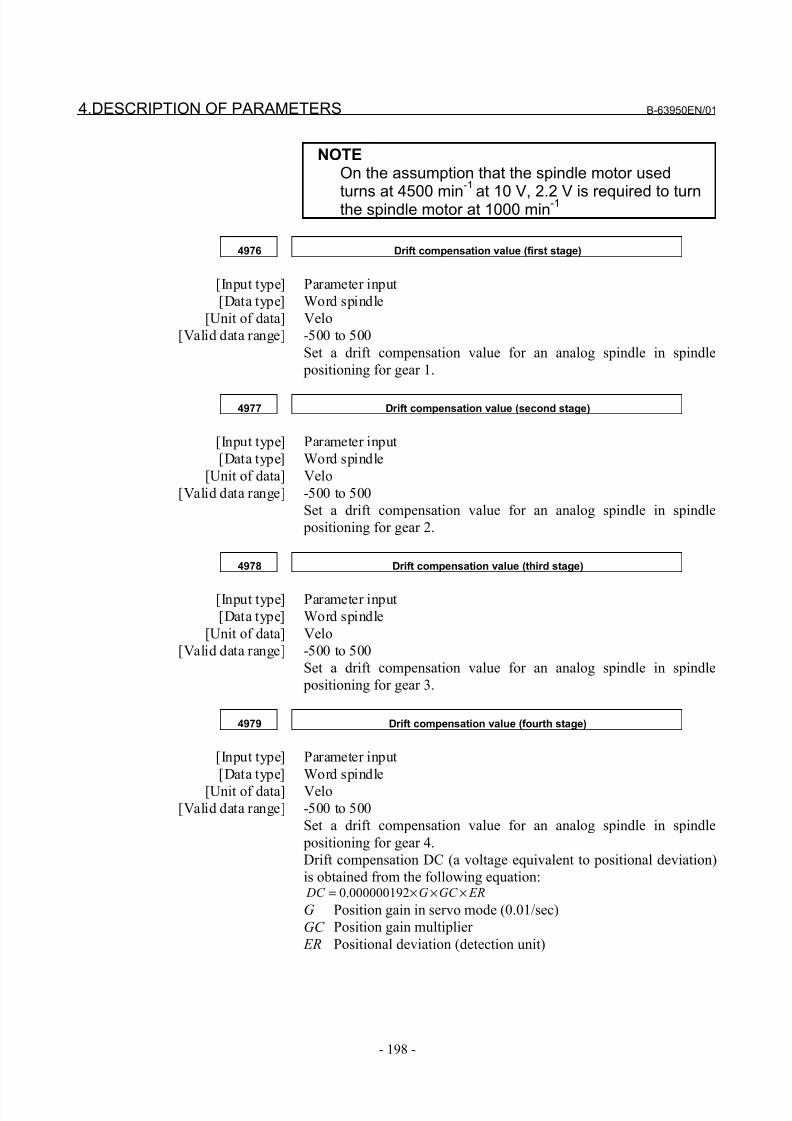
8/21/2019 30i Parameter Manual
http://slidepdf.com/reader/full/30i-parameter-manual 210/493
4.DESCRIPTION OF PARAMETERS B-63950EN/01
- 198 -
NOTEOn the assumption that the spindle motor used
turns at 4500 min
-1
at 10 V, 2.2 V is required to turnthe spindle motor at 1000 min-1
4976 Drift compensation value (first stage)
[Input type] Parameter input
[Data type] Word spindle
[Unit of data] Velo
[Valid data range] -500 to 500
Set a drift compensation value for an analog spindle in spindle
positioning for gear 1.
4977 Drift compensation value (second stage)
[Input type] Parameter input
[Data type] Word spindle
[Unit of data] Velo
[Valid data range] -500 to 500
Set a drift compensation value for an analog spindle in spindle
positioning for gear 2.
4978 Drift compensation value (third stage)
[Input type] Parameter input
[Data type] Word spindle
[Unit of data] Velo
[Valid data range] -500 to 500
Set a drift compensation value for an analog spindle in spindle
positioning for gear 3.
4979 Drift compensation value (fourth stage)
[Input type] Parameter input
[Data type] Word spindle
[Unit of data] Velo
[Valid data range] -500 to 500
Set a drift compensation value for an analog spindle in spindle
positioning for gear 4.
Drift compensation DC (a voltage equivalent to positional deviation)
is obtained from the following equation: ERGC G DC ×××= 000000192.0
G Position gain in servo mode (0.01/sec)
GC Position gain multiplier
ER Positional deviation (detection unit)
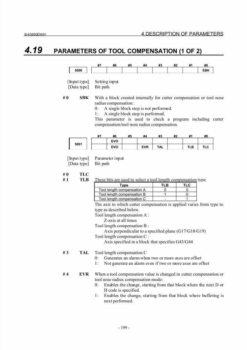
8/21/2019 30i Parameter Manual
http://slidepdf.com/reader/full/30i-parameter-manual 211/493
B-63950EN/01 4.DESCRIPTION OF PARAMETERS
- 199 -
4.19 PARAMETERS OF TOOL COMPENSATION (1 OF 2)
#7 #6 #5 #4 #3 #2 #1 #0
5000 SBK
[Input type] Setting input
[Data type] Bit path
# 0 SBK With a block created internally for cutter compensation or tool nose
radius compensation:
0: A single block stop is not performed.
1: A single block stop is performed.
This parameter is used to check a program including cutter
compensation/tool nose radius compensation.
#7 #6 #5 #4 #3 #2 #1 #0
EVO5001
EVO EVR TAL TLB TLC
[Input type] Parameter input
[Data type] Bit path
# 0 TLC
# 1 TLB These bits are used to select a tool length compensation type.
Type TLB TLCTool length compensation A 0 0
Tool length compensation B 1 0
Tool length compensation C - 1
The axis to which cutter compensation is applied varies from type to
type as described below.
Tool length compensation A :
Z-axis at all times
Tool length compensation B :
Axis perpendicular to a specified plane (G17/G18/G19)
Tool length compensation C :
Axis specified in a block that specifies G43/G44
# 3 TAL Tool length compensation C
0: Generates an alarm when two or more axes are offset
1: Not generate an alarm even if two or more axes are offset
# 4 EVR When a tool compensation value is changed in cutter compensation or
tool nose radius compensation mode:
0: Enables the change, starting from that block where the next D or
H code is specified.
1: Enables the change, starting from that block where buffering is
next performed.
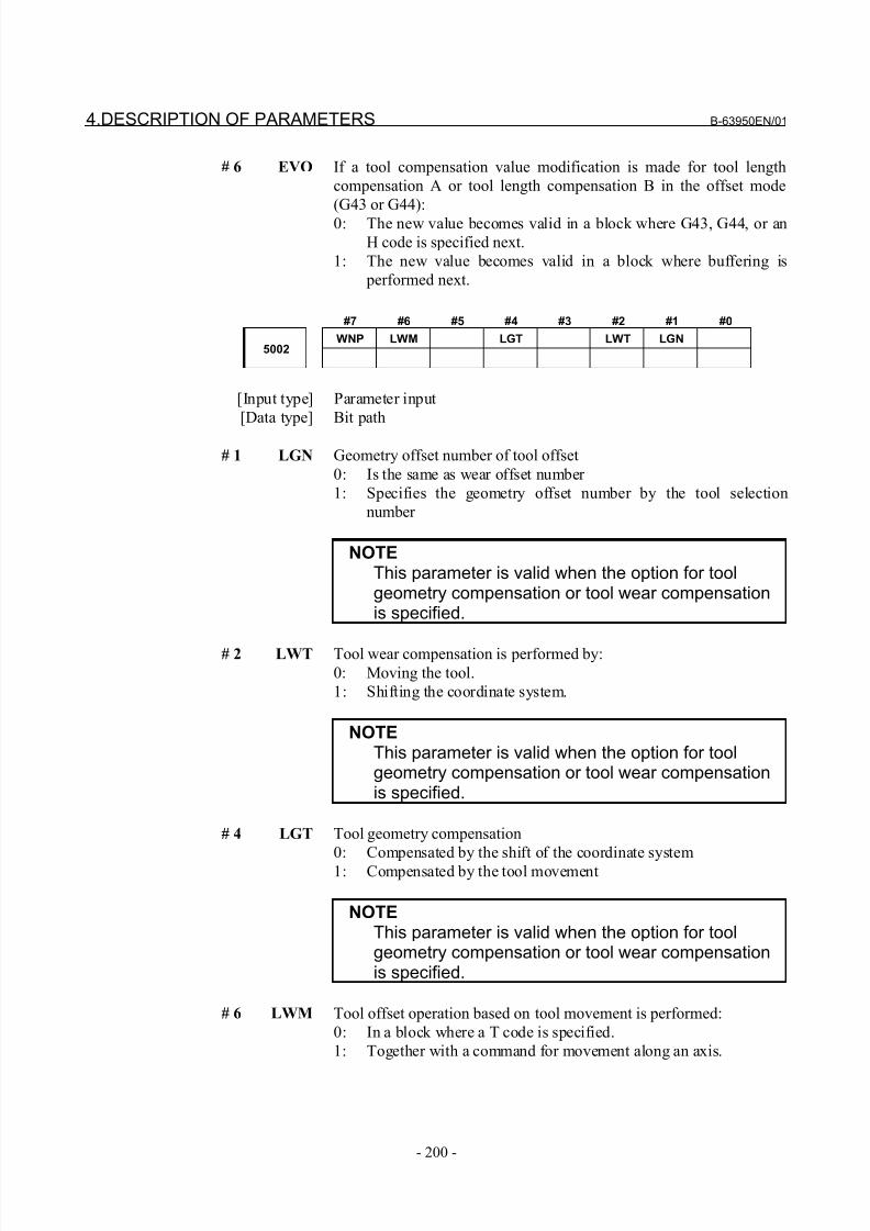
8/21/2019 30i Parameter Manual
http://slidepdf.com/reader/full/30i-parameter-manual 212/493
4.DESCRIPTION OF PARAMETERS B-63950EN/01
- 200 -
# 6 EVO If a tool compensation value modification is made for tool length
compensation A or tool length compensation B in the offset mode
(G43 or G44):
0: The new value becomes valid in a block where G43, G44, or an
H code is specified next.
1: The new value becomes valid in a block where buffering is
performed next.
#7 #6 #5 #4 #3 #2 #1 #0
WNP LWM LGT LWT LGN5002
[Input type] Parameter input
[Data type] Bit path
# 1 LGN Geometry offset number of tool offset
0: Is the same as wear offset number
1: Specifies the geometry offset number by the tool selection
number
NOTEThis parameter is valid when the option for toolgeometry compensation or tool wear compensationis specified.
# 2 LWT Tool wear compensation is performed by:
0: Moving the tool.
1: Shifting the coordinate system.
NOTEThis parameter is valid when the option for toolgeometry compensation or tool wear compensationis specified.
# 4 LGT Tool geometry compensation
0: Compensated by the shift of the coordinate system
1: Compensated by the tool movement
NOTEThis parameter is valid when the option for toolgeometry compensation or tool wear compensationis specified.
# 6 LWM Tool offset operation based on tool movement is performed:
0: In a block where a T code is specified.
1: Together with a command for movement along an axis.

8/21/2019 30i Parameter Manual
http://slidepdf.com/reader/full/30i-parameter-manual 213/493
B-63950EN/01 4.DESCRIPTION OF PARAMETERS
- 201 -
# 7 WNP Imaginary tool tip number used for tool nose radius compensation,
when the geometry/wear compensation function is equipped, is the
number specified by:
0: Geometry offset number
1: Wear offset number
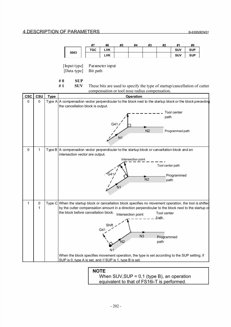
8/21/2019 30i Parameter Manual
http://slidepdf.com/reader/full/30i-parameter-manual 214/493
4.DESCRIPTION OF PARAMETERS B-63950EN/01
- 202 -
#7 #6 #5 #4 #3 #2 #1 #0
TGC LVK SUV SUP5003
LVK SUV SUP
[Input type] Parameter input
[Data type] Bit path
# 0 SUP
# 1 SUV These bits are used to specify the type of startup/cancellation of cutter
compensation or tool nose radius compensation.
CSC CSU Type Operation
0 0 Type A A compensation vector perpendicular to the block next to the startup block or the block preceding
the cancellation block is output.
0 1 Type B A compensation vector perpendicular to the startup block or cancellation block and an
intersection vector are output.
1 0
1
Type C When the startup block or cancellation block specifies no movement operation, the tool is shifted
by the cutter compensation amount in a direction perpendicular to the block next to the startup or
the block before cancellation block.
When the block specifies movement operation, the type is set according to the SUP setting; if
SUP is 0, type A is set, and if SUP is 1, type B is set.
NOTEWhen SUV,SUP = 0,1 (type B), an operationequivalent to that of FS16i-T is performed.
Tool center
path
Programmed path
N1
N2
G41
N1
N2
N3
Intersection point
Shift
G41
Tool center path
N1
N2
Intersection point
G41 Programmed
path
Programmed
path
Tool center
ath
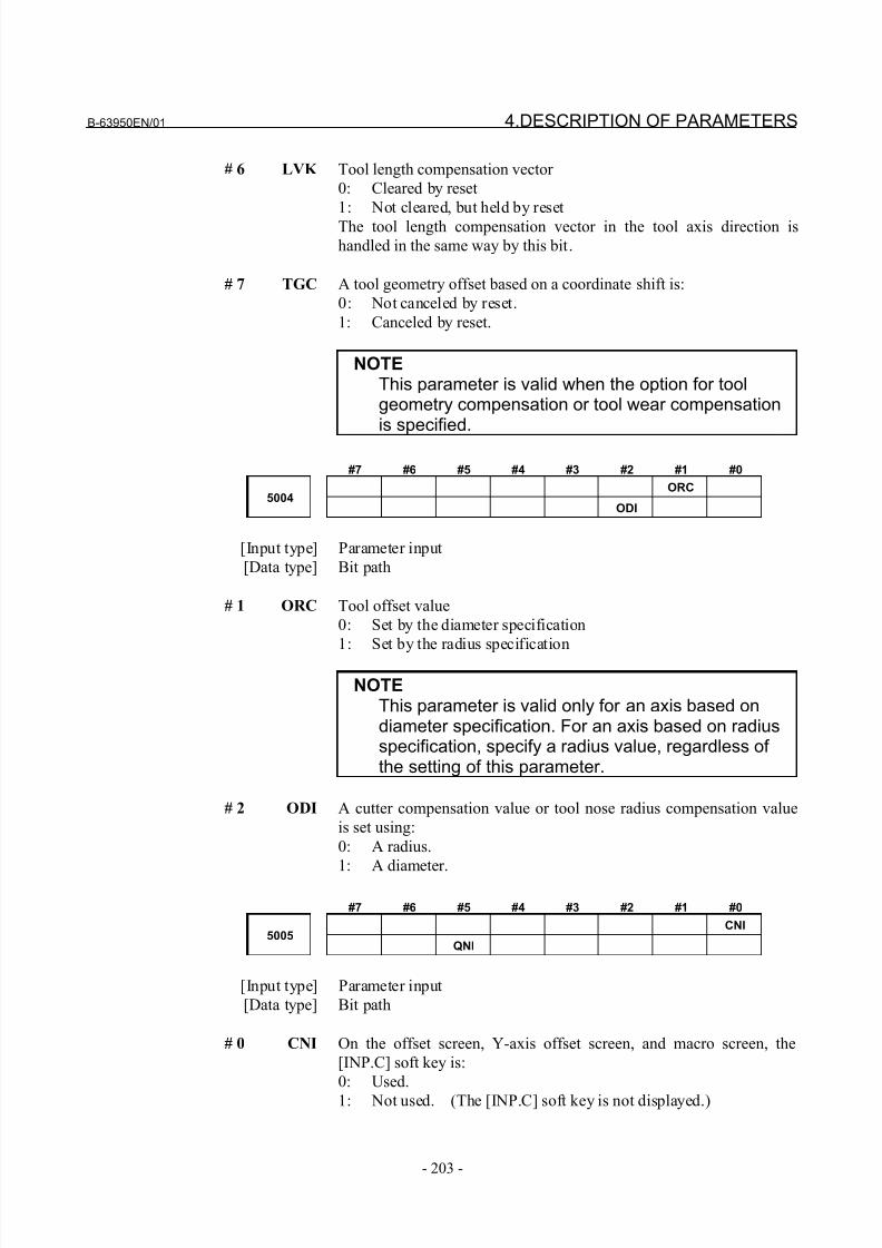
8/21/2019 30i Parameter Manual
http://slidepdf.com/reader/full/30i-parameter-manual 215/493
B-63950EN/01 4.DESCRIPTION OF PARAMETERS
- 203 -
# 6 LVK Tool length compensation vector
0: Cleared by reset
1: Not cleared, but held by reset
The tool length compensation vector in the tool axis direction is
handled in the same way by this bit.
# 7 TGC A tool geometry offset based on a coordinate shift is:
0: Not canceled by reset.
1: Canceled by reset.
NOTEThis parameter is valid when the option for toolgeometry compensation or tool wear compensationis specified.
#7 #6 #5 #4 #3 #2 #1 #0
ORC5004
ODI
[Input type] Parameter input
[Data type] Bit path
# 1 ORC Tool offset value
0: Set by the diameter specification
1: Set by the radius specification
NOTEThis parameter is valid only for an axis based ondiameter specification. For an axis based on radiusspecification, specify a radius value, regardless of the setting of this parameter.
# 2 ODI A cutter compensation value or tool nose radius compensation value
is set using:
0: A radius.
1: A diameter.
#7 #6 #5 #4 #3 #2 #1 #0
CNI5005
QNI
[Input type] Parameter input
[Data type] Bit path
# 0 CNI On the offset screen, Y-axis offset screen, and macro screen, the
[INP.C] soft key is:
0: Used.
1: Not used. (The [INP.C] soft key is not displayed.)
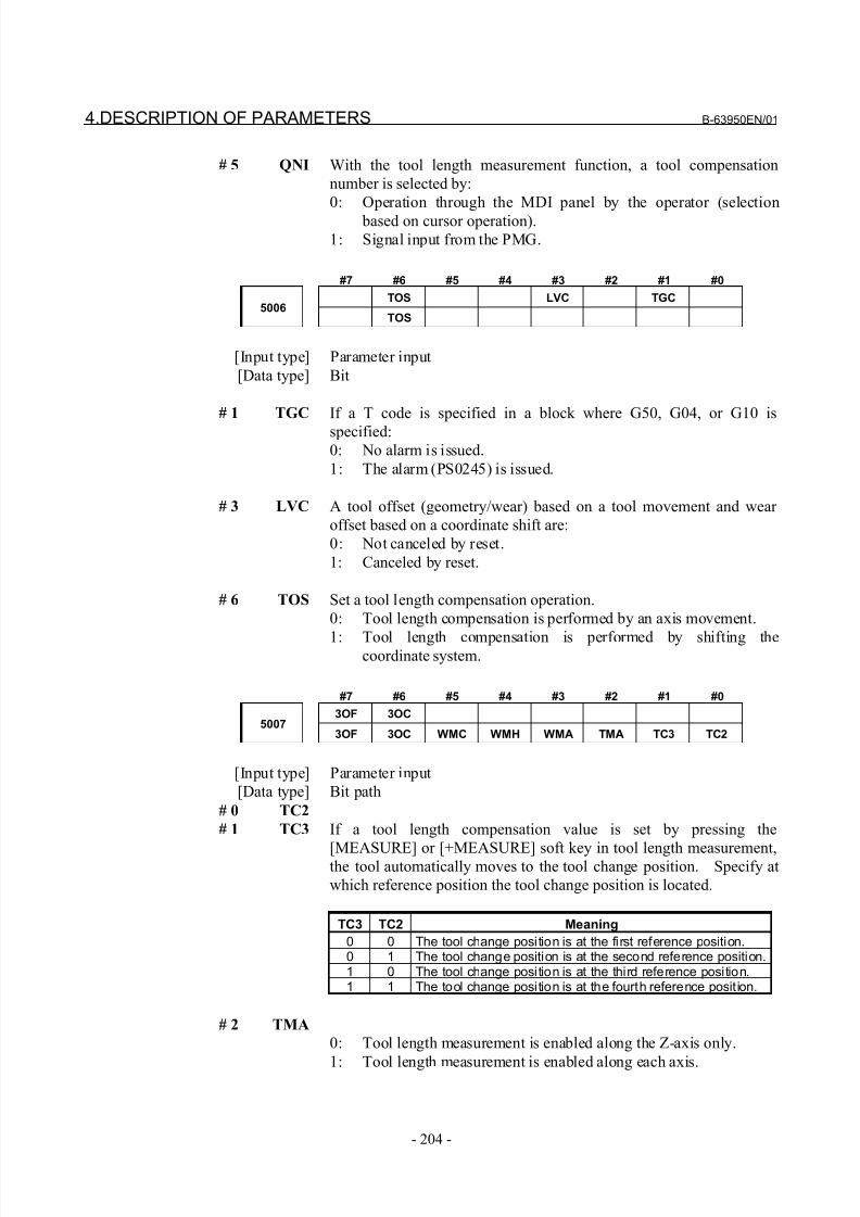
8/21/2019 30i Parameter Manual
http://slidepdf.com/reader/full/30i-parameter-manual 216/493
4.DESCRIPTION OF PARAMETERS B-63950EN/01
- 204 -
# 5 QNI With the tool length measurement function, a tool compensation
number is selected by:
0: Operation through the MDI panel by the operator (selection
based on cursor operation).
1: Signal input from the PMG.
#7 #6 #5 #4 #3 #2 #1 #0
TOS LVC TGC5006
TOS
[Input type] Parameter input
[Data type] Bit
# 1 TGC If a T code is specified in a block where G50, G04, or G10 is
specified:0: No alarm is issued.
1: The alarm (PS0245) is issued.
# 3 LVC A tool offset (geometry/wear) based on a tool movement and wear
offset based on a coordinate shift are:
0: Not canceled by reset.
1: Canceled by reset.
# 6 TOS Set a tool length compensation operation.
0: Tool length compensation is performed by an axis movement.
1: Tool length compensation is performed by shifting thecoordinate system.
#7 #6 #5 #4 #3 #2 #1 #0
3OF 3OC5007
3OF 3OC WMC WMH WMA TMA TC3 TC2
[Input type] Parameter input
[Data type] Bit path
# 0 TC2
# 1 TC3 If a tool length compensation value is set by pressing the
[MEASURE] or [+MEASURE] soft key in tool length measurement,the tool automatically moves to the tool change position. Specify at
which reference position the tool change position is located.
TC3 TC2 Meaning
0 0 The tool change position is at the first reference position.0 1 The tool change position is at the second reference position.1 0 The tool change position is at the third reference position.1 1 The tool change position is at the fourth reference posit ion.
# 2 TMA
0: Tool length measurement is enabled along the Z-axis only.
1: Tool length measurement is enabled along each axis.
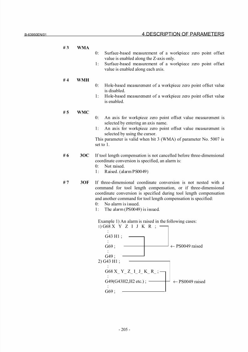
8/21/2019 30i Parameter Manual
http://slidepdf.com/reader/full/30i-parameter-manual 217/493
B-63950EN/01 4.DESCRIPTION OF PARAMETERS
- 205 -
# 3 WMA
0: Surface-based measurement of a workpiece zero point offset
value is enabled along the Z-axis only.
1: Surface-based measurement of a workpiece zero point offset
value is enabled along each axis.
# 4 WMH
0: Hole-based measurement of a workpiece zero point offset value
is disabled.
1: Hole-based measurement of a workpiece zero point offset value
is enabled.
# 5 WMC
0: An axis for workpiece zero point offset value measurement is
selected by entering an axis name.1: An axis for workpiece zero point offset value measurement is
selected by using the cursor.
This parameter is valid when bit 3 (WMA) of parameter No. 5007 is
set to 1.
# 6 3OC If tool length compensation is not cancelled before three-dimensional
coordinate conversion is specified, an alarm is:
0: Not raised.
1: Raised. (alarm PS0049)
# 7 3OF If three-dimensional coordinate conversion is not nested with a
command for tool length compensation, or if three-dimensional
coordinate conversion is specified during tool length compensation
and another command for tool length compensation is specified:
0: No alarm is issued.
1: The alarm (PS0049) is issued.
Example 1) An alarm is raised in the following cases:1) G68 X_ Y_ Z_ I_ J_ K_ R_ ; : G43 H1 ; :
G69 ; : G49 ;2) G43 H1 ; : G68 X_ Y_ Z_ I_ J_ K_ R_ ; : G49(G43H2,H2 etc.) ; : G69 ;
← PS0049 raised
← PS0049 raised
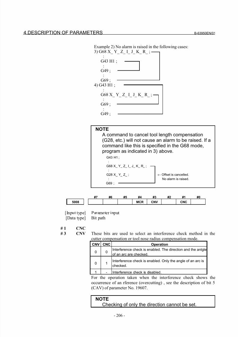
8/21/2019 30i Parameter Manual
http://slidepdf.com/reader/full/30i-parameter-manual 218/493
4.DESCRIPTION OF PARAMETERS B-63950EN/01
- 206 -
Example 2) No alarm is raised in the following cases:3) G68 X_ Y_ Z_ I_ J_ K_ R_ ; : G43 H1 ; : G49 ; : G69 ;4) G43 H1 ; : G68 X_ Y_ Z_ I_ J_ K_ R_ ; : G69 ; : G49 ;
NOTE A command to cancel tool length compensation(G28, etc.) will not cause an alarm to be raised. If acommand like this is specified in the G68 mode,program as indicated in 3) above.
G43 H1 ;
:
G68 X_ Y_ Z_ I_ J_ K_ R_ ;
:
G28 X_ Y_ Z_ ; ← Offset is cancelled.
: No alarm is raised.
G69 ;
#7 #6 #5 #4 #3 #2 #1 #0
5008 MCR CNV CNC
[Input type] Parameter input
[Data type] Bit path
# 1 CNC
# 3 CNV These bits are used to select an interference check method in the
cutter compensation or tool nose radius compensation mode.
CNV CNC Operation
0 0Interference check is enabled. The direction and the anlgle
of an arc are checked.
0 1Interference check is enabled. Only the angle of an arc is
checked.
1 - Interference check is disabled.
For the operation taken when the interference check shows the
occurrence of an rference (overcutting) , see the description of bit 5
(CAV) of parameter No. 19607.
NOTEChecking of only the direction cannot be set.
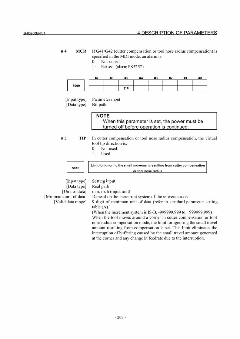
8/21/2019 30i Parameter Manual
http://slidepdf.com/reader/full/30i-parameter-manual 219/493
B-63950EN/01 4.DESCRIPTION OF PARAMETERS
- 207 -
# 4 MCR If G41/G42 (cutter compensation or tool nose radius compensation) is
specified in the MDI mode, an alarm is:
0: Not raised.
1: Raised. (alarm PS5257)
#7 #6 #5 #4 #3 #2 #1 #0
5009TIP
[Input type] Parameter input
[Data type] Bit path
NOTEWhen this parameter is set, the power must beturned off before operation is continued.
# 5 TIP In cutter compensation or tool nose radius compensation, the virtual
tool tip direction is:
0: Not used.
1: Used.
5010Limit for ignoring the small movement resulting from cutter compensation
or tool nose radius
[Input type] Setting input
[Data type] Real path
[Unit of data] mm, inch (input unit)
[Minimum unit of data] Depend on the increment system of the reference axis
[Valid data range] 9 digit of minimum unit of data (refer to standard parameter setting
table (A) )
(When the increment system is IS-B, -999999.999 to +999999.999)
When the tool moves around a corner in cutter compensation or tool
nose radius compensation mode, the limit for ignoring the small travel
amount resulting from compensation is set. This limit eliminates the
interruption of buffering caused by the small travel amount generated
at the corner and any change in feedrate due to the interruption.
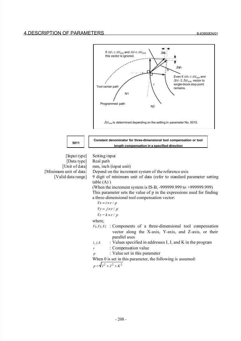
8/21/2019 30i Parameter Manual
http://slidepdf.com/reader/full/30i-parameter-manual 220/493
4.DESCRIPTION OF PARAMETERS B-63950EN/01
- 208 -
Even if ∆Vx ≤ ∆Vlimit and
∆VY ≤ ∆Vlimit, vector to
single-block stop point
remains.Tool center path
Programmed path
If ∆Vx ≤ ∆Vlimit and ∆VY≤ ∆Vlimit,
this vector is ignored.
S∆VY
∆Vx
r
r
N1
N2
∆Vlimit is determined depending on the setting in parameter No. 5010.
5011Constant denominator for three-dimensional tool compensation or tool
length compensation in a specified direction
[Input type] Setting input
[Data type] Real path
[Unit of data] mm, inch (input unit)
[Minimum unit of data] Depend on the increment system of the reference axis
[Valid data range] 9 digit of minimum unit of data (refer to standard parameter setting
table (A) )
(When the increment system is IS-B, -999999.999 to +999999.999)
This parameter sets the value of p in the expressions used for finding
a three-dimensional tool compensation vector: pr iVx /×=
pr jVy /×=
pr k Vz /×=
where,
Vz VyVx ,, : Components of a three-dimensional tool compensation
vector along the X-axis, Y-axis, and Z-axis, or their
parallel axesk ji ,, : Values specified in addresses I, J, and K in the program
r : Compensation value
p : Value set in this parameter
When 0 is set in this parameter, the following is assumed:222 K J I p ++=
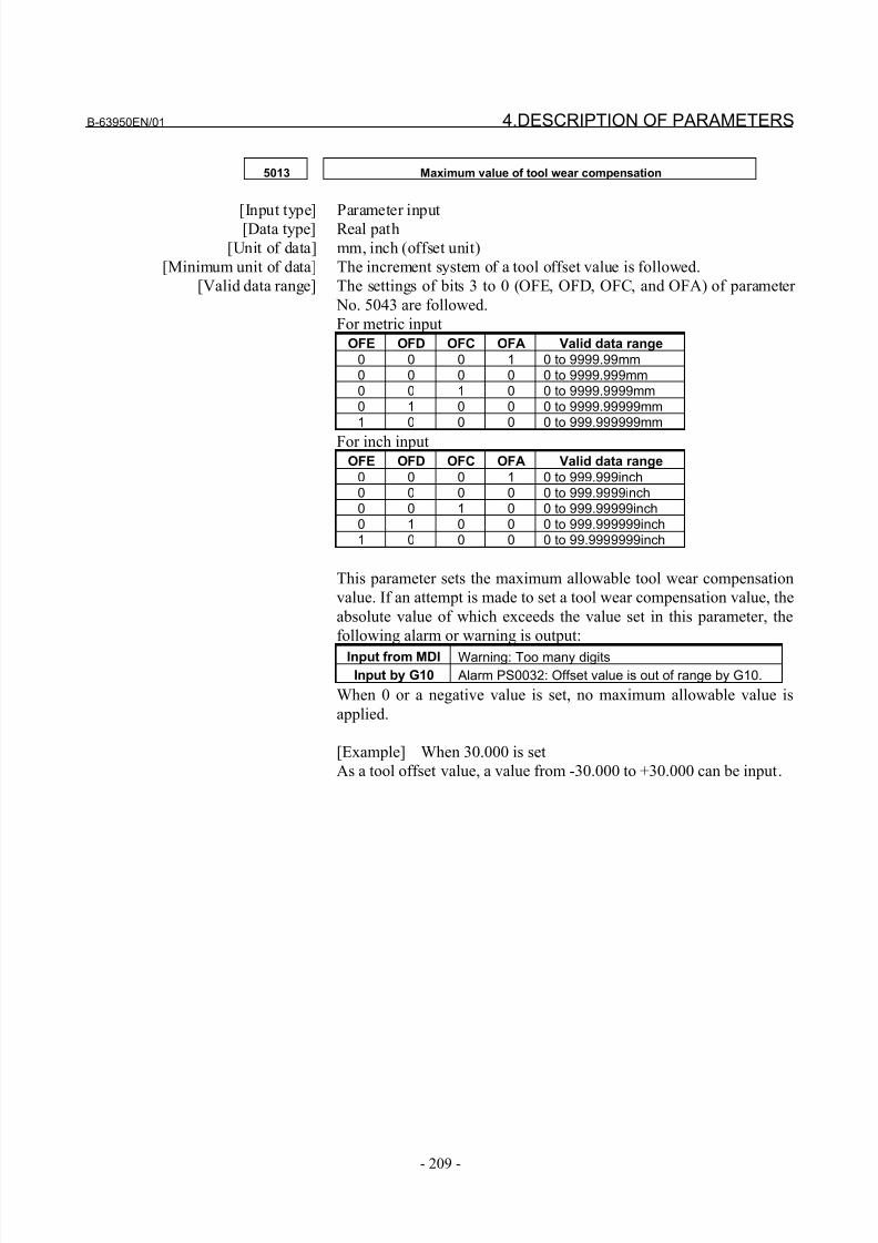
8/21/2019 30i Parameter Manual
http://slidepdf.com/reader/full/30i-parameter-manual 221/493
B-63950EN/01 4.DESCRIPTION OF PARAMETERS
- 209 -
5013 Maximum value of tool wear compensation
[Input type] Parameter input[Data type] Real path
[Unit of data] mm, inch (offset unit)
[Minimum unit of data] The increment system of a tool offset value is followed.
[Valid data range] The settings of bits 3 to 0 (OFE, OFD, OFC, and OFA) of parameter
No. 5043 are followed.
For metric input
OFE OFD OFC OFA Valid data range
0 0 0 1 0 to 9999.99mm0 0 0 0 0 to 9999.999mm0 0 1 0 0 to 9999.9999mm0 1 0 0 0 to 9999.99999mm1 0 0 0 0 to 999.999999mm
For inch inputOFE OFD OFC OFA Valid data range
0 0 0 1 0 to 999.999inch0 0 0 0 0 to 999.9999inch0 0 1 0 0 to 999.99999inch0 1 0 0 0 to 999.999999inch1 0 0 0 0 to 99.9999999inch
This parameter sets the maximum allowable tool wear compensation
value. If an attempt is made to set a tool wear compensation value, the
absolute value of which exceeds the value set in this parameter, the
following alarm or warning is output:
Input from MDI Warning: Too many digits
Input by G10 Alarm PS0032: Offset value is out of range by G10.
When 0 or a negative value is set, no maximum allowable value is
applied.
[Example] When 30.000 is set
As a tool offset value, a value from -30.000 to +30.000 can be input.
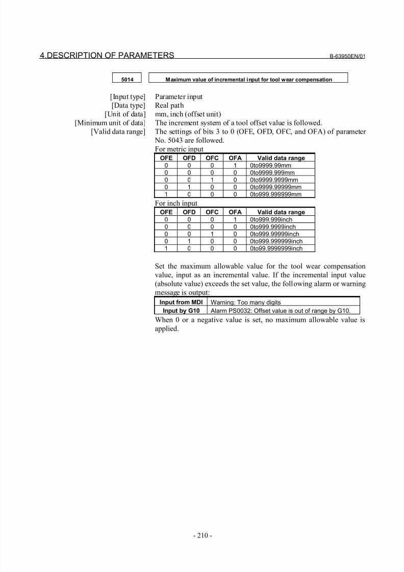
8/21/2019 30i Parameter Manual
http://slidepdf.com/reader/full/30i-parameter-manual 222/493
4.DESCRIPTION OF PARAMETERS B-63950EN/01
- 210 -
5014 Maximum value of incremental input for tool wear compensation
[Input type] Parameter input[Data type] Real path
[Unit of data] mm, inch (offset unit)
[Minimum unit of data] The increment system of a tool offset value is followed.
[Valid data range] The settings of bits 3 to 0 (OFE, OFD, OFC, and OFA) of parameter
No. 5043 are followed.
For metric input
OFE OFD OFC OFA Valid data range
0 0 0 1 0to9999.99mm0 0 0 0 0to9999.999mm0 0 1 0 0to9999.9999mm0 1 0 0 0to9999.99999mm1 0 0 0 0to999.999999mm
For inch inputOFE OFD OFC OFA Valid data range
0 0 0 1 0to999.999inch0 0 0 0 0to999.9999inch0 0 1 0 0to999.99999inch0 1 0 0 0to999.999999inch1 0 0 0 0to99.9999999inch
Set the maximum allowable value for the tool wear compensation
value, input as an incremental value. If the incremental input value
(absolute value) exceeds the set value, the following alarm or warning
message is output:
Input from MDI Warning: Too many digits
Input by G10 Alarm PS0032: Offset value is out of range by G10.
When 0 or a negative value is set, no maximum allowable value is
applied.
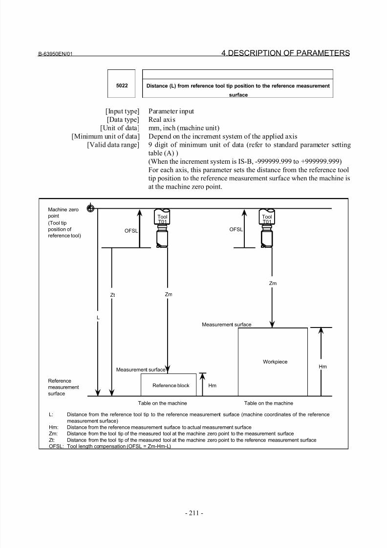
8/21/2019 30i Parameter Manual
http://slidepdf.com/reader/full/30i-parameter-manual 223/493
B-63950EN/01 4.DESCRIPTION OF PARAMETERS
- 211 -
5022 Distance (L) from reference tool tip position to the reference measurement
surface
[Input type] Parameter input
[Data type] Real axis
[Unit of data] mm, inch (machine unit)
[Minimum unit of data] Depend on the increment system of the applied axis
[Valid data range] 9 digit of minimum unit of data (refer to standard parameter setting
table (A) )
(When the increment system is IS-B, -999999.999 to +999999.999)
For each axis, this parameter sets the distance from the reference tool
tip position to the reference measurement surface when the machine is
at the machine zero point.
(Tool tip
position of
reference tool)
Workpiece
Measurement surface
OFSL OFSL
Measurement surface
Hm
Machine zero
point
Zm
Zm
L
Hm
Reference blockReference
measurement
surface
L: Distance from the reference tool tip to the reference measurement surface (machine coordinates of the reference
measurement surface)
Hm: Distance from the reference measurement surface to actual measurement surface
Zm: Distance from the tool tip of the measured tool at the machine zero point to the measurement surface
Zt: Distance from the tool tip of the measured tool at the machine zero point to the reference measurement surface
OFSL: Tool length compensation (OFSL = Zm-Hm-L)
Zt
Table on the machine Table on the machine
ToolT01
ToolT01
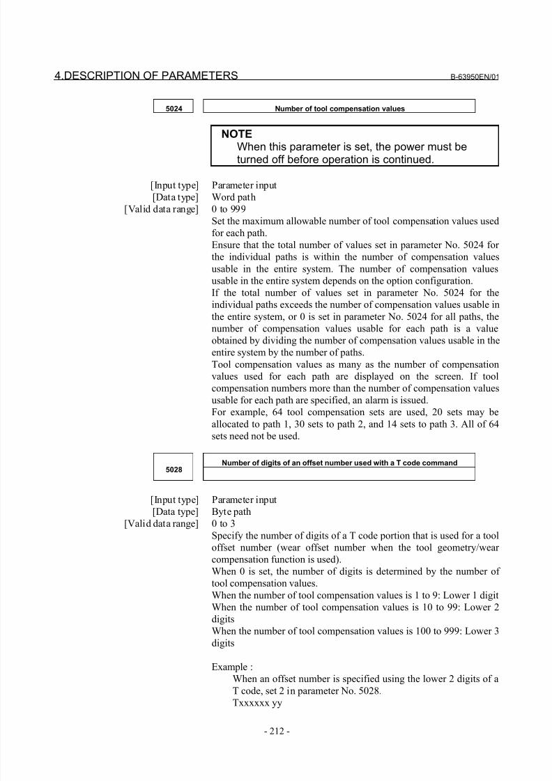
8/21/2019 30i Parameter Manual
http://slidepdf.com/reader/full/30i-parameter-manual 224/493
4.DESCRIPTION OF PARAMETERS B-63950EN/01
- 212 -
5024 Number of tool compensation values
NOTEWhen this parameter is set, the power must beturned off before operation is continued.
[Input type] Parameter input
[Data type] Word path
[Valid data range] 0 to 999
Set the maximum allowable number of tool compensation values used
for each path.
Ensure that the total number of values set in parameter No. 5024 for
the individual paths is within the number of compensation values
usable in the entire system. The number of compensation valuesusable in the entire system depends on the option configuration.
If the total number of values set in parameter No. 5024 for the
individual paths exceeds the number of compensation values usable in
the entire system, or 0 is set in parameter No. 5024 for all paths, the
number of compensation values usable for each path is a value
obtained by dividing the number of compensation values usable in the
entire system by the number of paths.
Tool compensation values as many as the number of compensation
values used for each path are displayed on the screen. If tool
compensation numbers more than the number of compensation values
usable for each path are specified, an alarm is issued.
For example, 64 tool compensation sets are used, 20 sets may beallocated to path 1, 30 sets to path 2, and 14 sets to path 3. All of 64
sets need not be used.
Number of digits of an offset number used with a T code command5028
[Input type] Parameter input
[Data type] Byte path
[Valid data range] 0 to 3
Specify the number of digits of a T code portion that is used for a tool
offset number (wear offset number when the tool geometry/wear compensation function is used).
When 0 is set, the number of digits is determined by the number of
tool compensation values.
When the number of tool compensation values is 1 to 9: Lower 1 digit
When the number of tool compensation values is 10 to 99: Lower 2
digits
When the number of tool compensation values is 100 to 999: Lower 3
digits
Example :
When an offset number is specified using the lower 2 digits of a
T code, set 2 in parameter No. 5028.
Txxxxxx yy
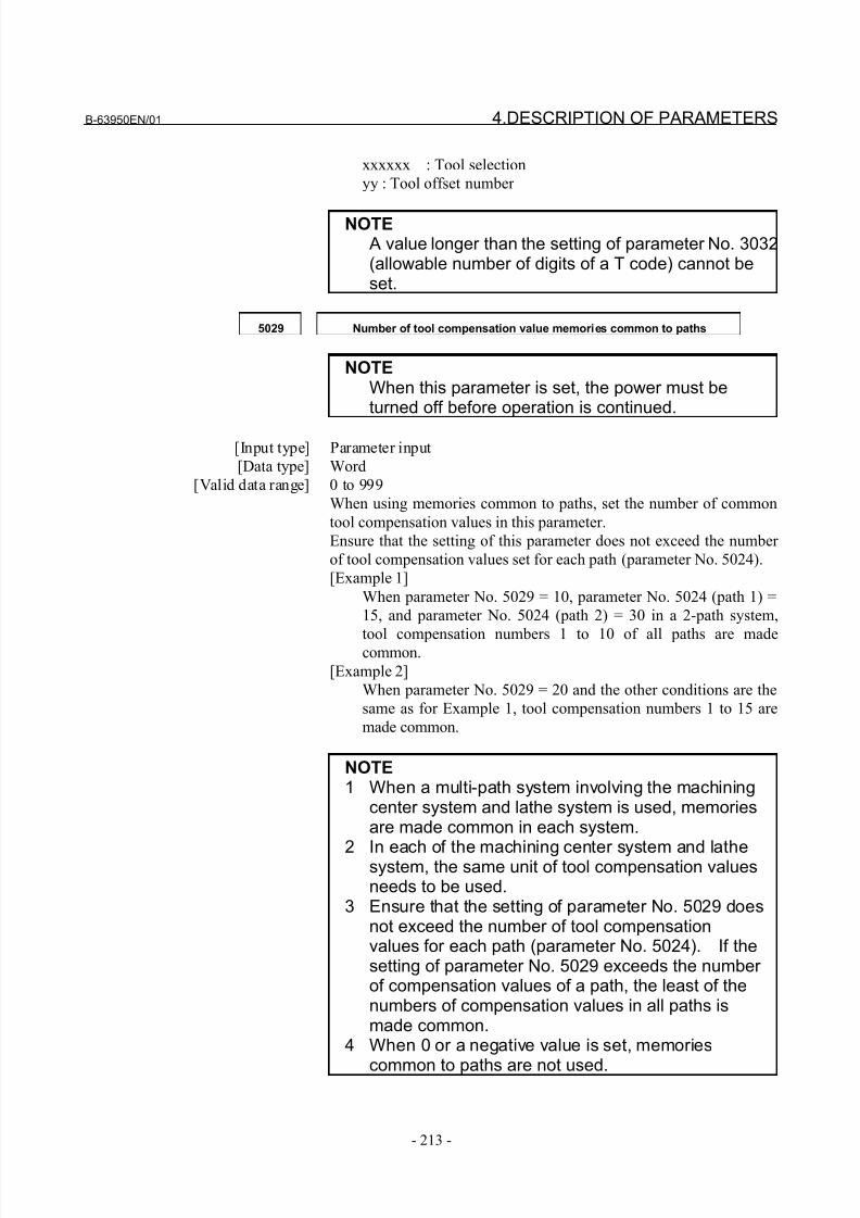
8/21/2019 30i Parameter Manual
http://slidepdf.com/reader/full/30i-parameter-manual 225/493
B-63950EN/01 4.DESCRIPTION OF PARAMETERS
- 213 -
xxxxxx : Tool selection
yy : Tool offset number
NOTE A value longer than the setting of parameter No. 3032(allowable number of digits of a T code) cannot beset.
5029 Number of tool compensation value memories common to paths
NOTEWhen this parameter is set, the power must beturned off before operation is continued.
[Input type] Parameter input
[Data type] Word
[Valid data range] 0 to 999
When using memories common to paths, set the number of common
tool compensation values in this parameter.
Ensure that the setting of this parameter does not exceed the number
of tool compensation values set for each path (parameter No. 5024).
[Example 1]
When parameter No. 5029 = 10, parameter No. 5024 (path 1) =
15, and parameter No. 5024 (path 2) = 30 in a 2-path system,
tool compensation numbers 1 to 10 of all paths are madecommon.
[Example 2]
When parameter No. 5029 = 20 and the other conditions are the
same as for Example 1, tool compensation numbers 1 to 15 are
made common.
NOTE1 When a multi-path system involving the machining
center system and lathe system is used, memoriesare made common in each system.
2 In each of the machining center system and lathesystem, the same unit of tool compensation valuesneeds to be used.
3 Ensure that the setting of parameter No. 5029 doesnot exceed the number of tool compensationvalues for each path (parameter No. 5024). If thesetting of parameter No. 5029 exceeds the number of compensation values of a path, the least of thenumbers of compensation values in all paths ismade common.
4 When 0 or a negative value is set, memories
common to paths are not used.
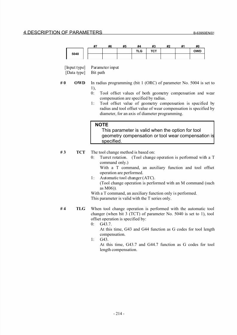
8/21/2019 30i Parameter Manual
http://slidepdf.com/reader/full/30i-parameter-manual 226/493
4.DESCRIPTION OF PARAMETERS B-63950EN/01
- 214 -
#7 #6 #5 #4 #3 #2 #1 #0
TLG TCT OWD5040
[Input type] Parameter input
[Data type] Bit path
# 0 OWD In radius programming (bit 1 (ORC) of parameter No. 5004 is set to
1),
0: Tool offset values of both geometry compensation and wear
compensation are specified by radius.
1: Tool offset value of geometry compensation is specified by
radius and tool offset value of wear compensation is specified by
diameter, for an axis of diameter programming.
NOTEThis parameter is valid when the option for toolgeometry compensation or tool wear compensation isspecified.
# 3 TCT The tool change method is based on:
0: Turret rotation. (Tool change operation is performed with a T
command only.)
With a T command, an auxiliary function and tool offset
operation are performed.
1: Automatic tool changer (ATC).
(Tool change operation is performed with an M command (such
as M06)).
With a T command, an auxiliary function only is performed.
This parameter is valid with the T series only.
# 4 TLG When tool change operation is performed with the automatic tool
changer (when bit 3 (TCT) of parameter No. 5040 is set to 1), tool
offset operation is specified by:
0: G43.7.
At this time, G43 and G44 function as G codes for tool length
compensation.1: G43.
At this time, G43.7 and G44.7 function as G codes for tool
length compensation.
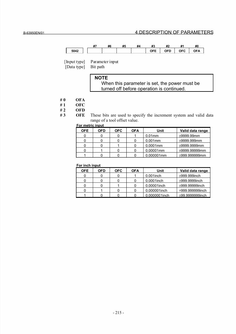
8/21/2019 30i Parameter Manual
http://slidepdf.com/reader/full/30i-parameter-manual 227/493
B-63950EN/01 4.DESCRIPTION OF PARAMETERS
- 215 -
#7 #6 #5 #4 #3 #2 #1 #0
5042 OFE OFD OFC OFA
[Input type] Parameter input
[Data type] Bit path
NOTEWhen this parameter is set, the power must beturned off before operation is continued.
# 0 OFA
# 1 OFC
# 2 OFD
# 3 OFE These bits are used to specify the increment system and valid datarange of a tool offset value.For metric input
OFE OFD OFC OFA Unit Valid data range
0 0 0 1 0.01mm ±9999.99mm
0 0 0 0 0.001mm ±9999.999mm
0 0 1 0 0.0001mm ±9999.9999mm
0 1 0 0 0.00001mm ±9999.99999mm
1 0 0 0 0.000001mm ±999.999999mm
For inch input
OFE OFD OFC OFA Unit Valid data range
0 0 0 1 0.001inch ±999.999inch0 0 0 0 0.0001inch ±999.9999inch
0 0 1 0 0.00001inch ±999.99999inch
0 1 0 0 0.000001inch ±999.999999inch
1 0 0 0 0.0000001inch ±99.9999999inch
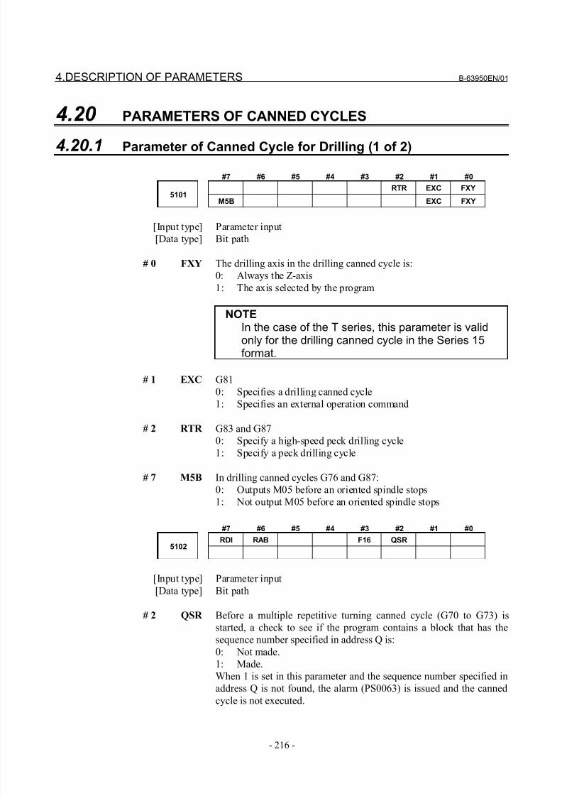
8/21/2019 30i Parameter Manual
http://slidepdf.com/reader/full/30i-parameter-manual 228/493
4.DESCRIPTION OF PARAMETERS B-63950EN/01
- 216 -
4.20 PARAMETERS OF CANNED CYCLES
4.20.1 Parameter of Canned Cycle for Drilling (1 of 2)
#7 #6 #5 #4 #3 #2 #1 #0
RTR EXC FXY5101
M5B EXC FXY
[Input type] Parameter input
[Data type] Bit path
# 0 FXY The drilling axis in the drilling canned cycle is:
0: Always the Z-axis1: The axis selected by the program
NOTEIn the case of the T series, this parameter is validonly for the drilling canned cycle in the Series 15format.
# 1 EXC G81
0: Specifies a drilling canned cycle
1: Specifies an external operation command
# 2 RTR G83 and G87
0: Specify a high-speed peck drilling cycle
1: Specify a peck drilling cycle
# 7 M5B In drilling canned cycles G76 and G87:
0: Outputs M05 before an oriented spindle stops
1: Not output M05 before an oriented spindle stops
#7 #6 #5 #4 #3 #2 #1 #0
RDI RAB F16 QSR5102
[Input type] Parameter input
[Data type] Bit path
# 2 QSR Before a multiple repetitive turning canned cycle (G70 to G73) is
started, a check to see if the program contains a block that has the
sequence number specified in address Q is:
0: Not made.
1: Made.
When 1 is set in this parameter and the sequence number specified in
address Q is not found, the alarm (PS0063) is issued and the canned
cycle is not executed.
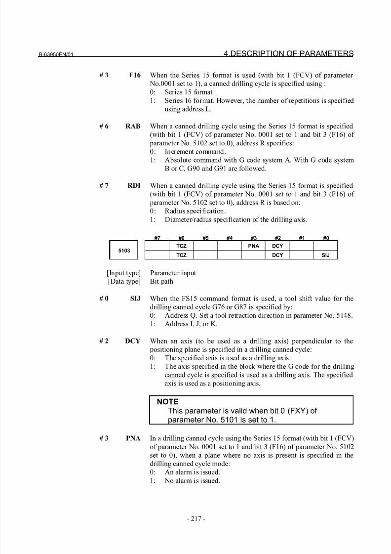
8/21/2019 30i Parameter Manual
http://slidepdf.com/reader/full/30i-parameter-manual 229/493
B-63950EN/01 4.DESCRIPTION OF PARAMETERS
- 217 -
# 3 F16 When the Series 15 format is used (with bit 1 (FCV) of parameter
No.0001 set to 1), a canned drilling cycle is specified using :
0: Series 15 format
1: Series 16 format. However, the number of repetitions is specified
using address L.
# 6 RAB When a canned drilling cycle using the Series 15 format is specified
(with bit 1 (FCV) of parameter No. 0001 set to 1 and bit 3 (F16) of
parameter No. 5102 set to 0), address R specifies:
0: Increment command.
1: Absolute command with G code system A. With G code system
B or C, G90 and G91 are followed.
# 7 RDI When a canned drilling cycle using the Series 15 format is specified
(with bit 1 (FCV) of parameter No. 0001 set to 1 and bit 3 (F16) of parameter No. 5102 set to 0), address R is based on:
0: Radius specification.
1: Diameter/radius specification of the drilling axis.
#7 #6 #5 #4 #3 #2 #1 #0
TCZ PNA DCY5103
TCZ DCY SIJ
[Input type] Parameter input
[Data type] Bit path
# 0 SIJ When the FS15 command format is used, a tool shift value for the
drilling canned cycle G76 or G87 is specified by:
0: Address Q. Set a tool retraction direction in parameter No. 5148.
1: Address I, J, or K.
# 2 DCY When an axis (to be used as a drilling axis) perpendicular to the
positioning plane is specified in a drilling canned cycle:
0: The specified axis is used as a drilling axis.
1: The axis specified in the block where the G code for the drilling
canned cycle is specified is used as a drilling axis. The specified
axis is used as a positioning axis.
NOTEThis parameter is valid when bit 0 (FXY) of parameter No. 5101 is set to 1.
# 3 PNA In a drilling canned cycle using the Series 15 format (with bit 1 (FCV)
of parameter No. 0001 set to 1 and bit 3 (F16) of parameter No. 5102
set to 0), when a plane where no axis is present is specified in the
drilling canned cycle mode:
0: An alarm is issued.
1: No alarm is issued.
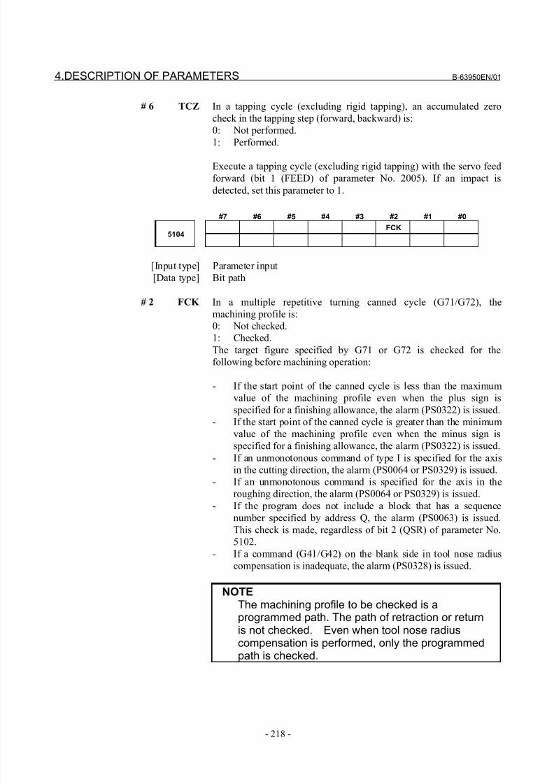
8/21/2019 30i Parameter Manual
http://slidepdf.com/reader/full/30i-parameter-manual 230/493
4.DESCRIPTION OF PARAMETERS B-63950EN/01
- 218 -
# 6 TCZ In a tapping cycle (excluding rigid tapping), an accumulated zero
check in the tapping step (forward, backward) is:
0: Not performed.
1: Performed.
Execute a tapping cycle (excluding rigid tapping) with the servo feed
forward (bit 1 (FEED) of parameter No. 2005). If an impact is
detected, set this parameter to 1.
#7 #6 #5 #4 #3 #2 #1 #0
FCK5104
[Input type] Parameter input
[Data type] Bit path
# 2 FCK In a multiple repetitive turning canned cycle (G71/G72), the
machining profile is:
0: Not checked.
1: Checked.
The target figure specified by G71 or G72 is checked for the
following before machining operation:
- If the start point of the canned cycle is less than the maximum
value of the machining profile even when the plus sign is
specified for a finishing allowance, the alarm (PS0322) is issued.- If the start point of the canned cycle is greater than the minimum
value of the machining profile even when the minus sign is
specified for a finishing allowance, the alarm (PS0322) is issued.
- If an unmonotonous command of type I is specified for the axis
in the cutting direction, the alarm (PS0064 or PS0329) is issued.
- If an unmonotonous command is specified for the axis in the
roughing direction, the alarm (PS0064 or PS0329) is issued.
- If the program does not include a block that has a sequence
number specified by address Q, the alarm (PS0063) is issued.
This check is made, regardless of bit 2 (QSR) of parameter No.
5102.
- If a command (G41/G42) on the blank side in tool nose radius
compensation is inadequate, the alarm (PS0328) is issued.
NOTEThe machining profile to be checked is aprogrammed path. The path of retraction or returnis not checked. Even when tool nose radiuscompensation is performed, only the programmedpath is checked.
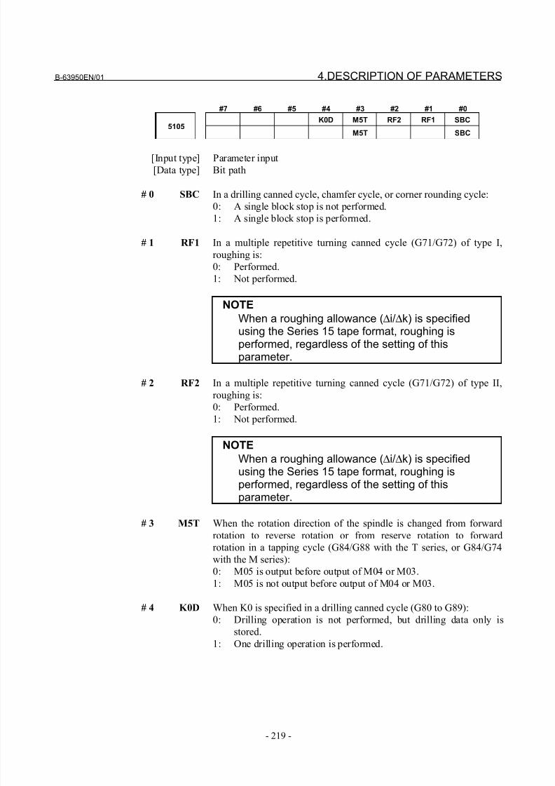
8/21/2019 30i Parameter Manual
http://slidepdf.com/reader/full/30i-parameter-manual 231/493
B-63950EN/01 4.DESCRIPTION OF PARAMETERS
- 219 -
#7 #6 #5 #4 #3 #2 #1 #0
K0D M5T RF2 RF1 SBC5105
M5T SBC
[Input type] Parameter input
[Data type] Bit path
# 0 SBC In a drilling canned cycle, chamfer cycle, or corner rounding cycle:
0: A single block stop is not performed.
1: A single block stop is performed.
# 1 RF1 In a multiple repetitive turning canned cycle (G71/G72) of type I,
roughing is:
0: Performed.
1: Not performed.
NOTE
When a roughing allowance (∆i/∆k) is specifiedusing the Series 15 tape format, roughing isperformed, regardless of the setting of thisparameter.
# 2 RF2 In a multiple repetitive turning canned cycle (G71/G72) of type II,
roughing is:
0: Performed.
1: Not performed.
NOTE
When a roughing allowance (∆i/∆k) is specifiedusing the Series 15 tape format, roughing isperformed, regardless of the setting of thisparameter.
# 3 M5T When the rotation direction of the spindle is changed from forward
rotation to reverse rotation or from reserve rotation to forward
rotation in a tapping cycle (G84/G88 with the T series, or G84/G74with the M series):
0: M05 is output before output of M04 or M03.
1: M05 is not output before output of M04 or M03.
# 4 K0D When K0 is specified in a drilling canned cycle (G80 to G89):
0: Drilling operation is not performed, but drilling data only is
stored.
1: One drilling operation is performed.
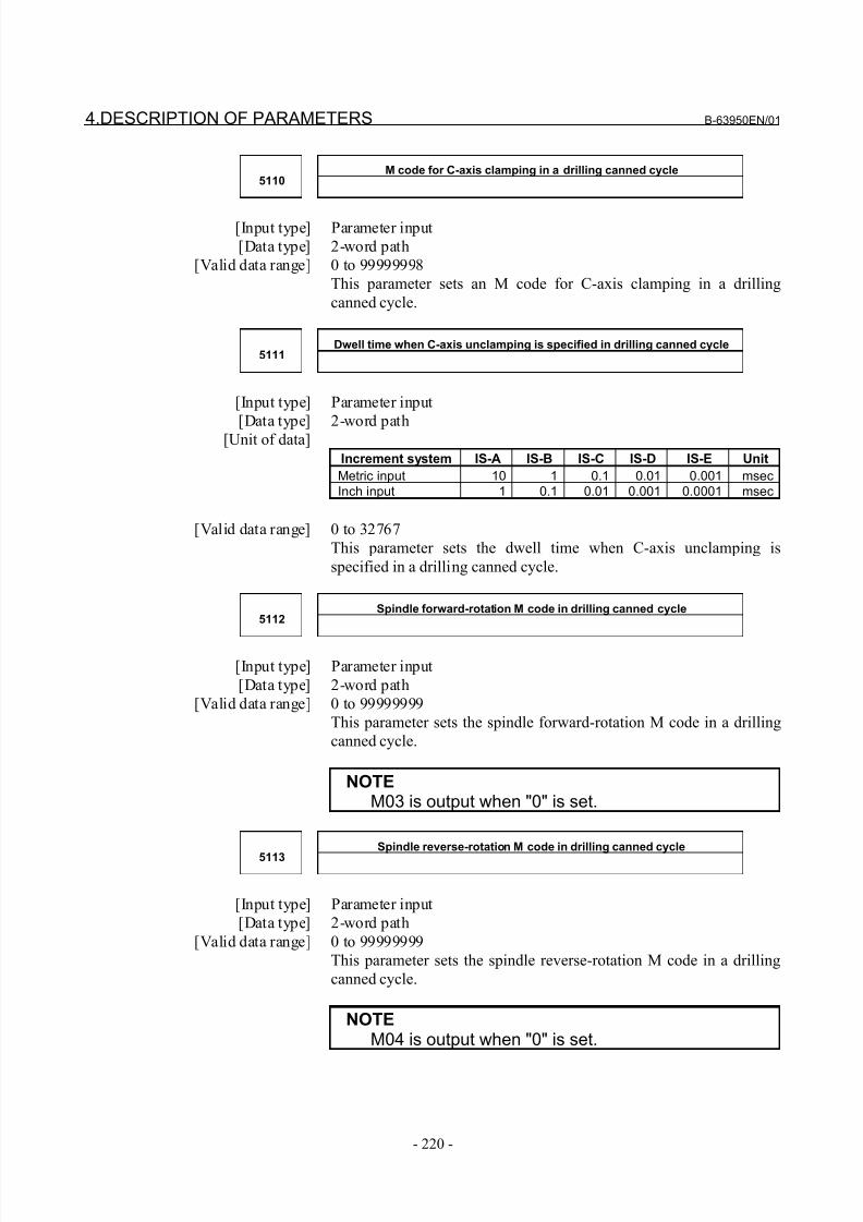
8/21/2019 30i Parameter Manual
http://slidepdf.com/reader/full/30i-parameter-manual 232/493
4.DESCRIPTION OF PARAMETERS B-63950EN/01
- 220 -
M code for C-axis clamping in a drilling canned cycle5110
[Input type] Parameter input
[Data type] 2-word path
[Valid data range] 0 to 99999998
This parameter sets an M code for C-axis clamping in a drilling
canned cycle.
Dwell time when C-axis unclamping is specified in drilling canned cycle5111
[Input type] Parameter input
[Data type] 2-word path[Unit of data]
Increment system IS-A IS-B IS-C IS-D IS-E Unit
Metric input 10 1 0.1 0.01 0.001 msecInch input 1 0.1 0.01 0.001 0.0001 msec
[Valid data range] 0 to 32767
This parameter sets the dwell time when C-axis unclamping is
specified in a drilling canned cycle.
Spindle forward-rotation M code in drilling canned cycle5112
[Input type] Parameter input
[Data type] 2-word path
[Valid data range] 0 to 99999999
This parameter sets the spindle forward-rotation M code in a drilling
canned cycle.
NOTEM03 is output when "0" is set.
Spindle reverse-rotation M code in drilling canned cycle
5113
[Input type] Parameter input
[Data type] 2-word path
[Valid data range] 0 to 99999999
This parameter sets the spindle reverse-rotation M code in a drilling
canned cycle.
NOTEM04 is output when "0" is set.
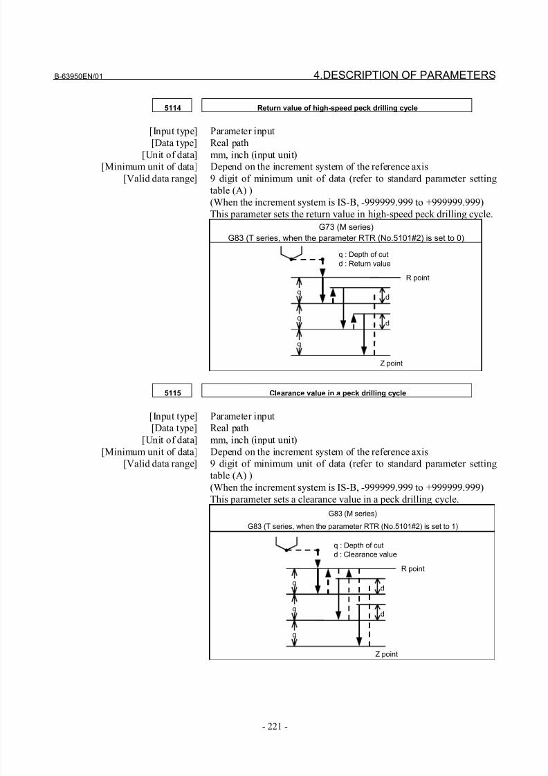
8/21/2019 30i Parameter Manual
http://slidepdf.com/reader/full/30i-parameter-manual 233/493
B-63950EN/01 4.DESCRIPTION OF PARAMETERS
- 221 -
5114 Return value of high-speed peck drilling cycle
[Input type] Parameter input[Data type] Real path
[Unit of data] mm, inch (input unit)
[Minimum unit of data] Depend on the increment system of the reference axis
[Valid data range] 9 digit of minimum unit of data (refer to standard parameter setting
table (A) )
(When the increment system is IS-B, -999999.999 to +999999.999)
This parameter sets the return value in high-speed peck drilling cycle.
G73 (M series)
G83 (T series, when the parameter RTR (No.5101#2) is set to 0)
5115 Clearance value in a peck drilling cycle
[Input type] Parameter input
[Data type] Real path
[Unit of data] mm, inch (input unit)
[Minimum unit of data] Depend on the increment system of the reference axis
[Valid data range] 9 digit of minimum unit of data (refer to standard parameter setting
table (A) )
(When the increment system is IS-B, -999999.999 to +999999.999)
This parameter sets a clearance value in a peck drilling cycle.
G83 (M series)
G83 (T series, when the parameter RTR (No.5101#2) is set to 1)
q
q
q
d
d
q : Depth of cutd : Return value
R point
Z point
q
q
q
d
d
q : Depth of cutd : Clearance value
R point
Z point
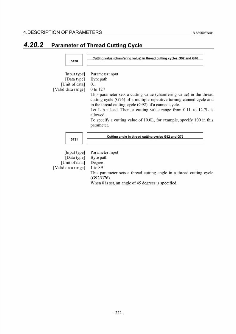
8/21/2019 30i Parameter Manual
http://slidepdf.com/reader/full/30i-parameter-manual 234/493
4.DESCRIPTION OF PARAMETERS B-63950EN/01
- 222 -
4.20.2 Parameter of Thread Cutting Cycle
Cutting value (chamfering value) in thread cutting cycles G92 and G765130
[Input type] Parameter input
[Data type] Byte path
[Unit of data] 0.1
[Valid data range] 0 to 127
This parameter sets a cutting value (chamfering value) in the thread
cutting cycle (G76) of a multiple repetitive turning canned cycle and
in the thread cutting cycle (G92) of a canned cycle.
Let L b a lead. Then, a cutting value range from 0.1L to 12.7L is
allowed.To specify a cutting value of 10.0L, for example, specify 100 in this
parameter.
Cutting angle in thread cutting cycles G92 and G765131
[Input type] Parameter input
[Data type] Byte path
[Unit of data] Degree
[Valid data range] 1 to 89
This parameter sets a thread cutting angle in a thread cutting cycle
(G92/G76).
When 0 is set, an angle of 45 degrees is specified.
8/21/2019 30i Parameter Manual
http://slidepdf.com/reader/full/30i-parameter-manual 235/493
B-63950EN/01 4.DESCRIPTION OF PARAMETERS
- 223 -
4.20.3 Parameter of Multiple Repetitive Canned Cycle
Depth of cut in multiple repetitive turning canned cycles G71 and G725132
[Input type] Parameter input
[Data type] Real path
[Unit of data] mm, inch (input unit)
[Minimum unit of data] Depend on the increment system of the reference axis
[Valid data range] 0 or positive 9 digit of minimum unit of data (refer to the standard
parameter setting table (B) )
(When the increment system is IS-B, 0.0 to +999999.999)
This parameter sets the depth of cut in multiple repetitive turning
canned cycles G71 and G72.This parameter is not used with the Series 15 tape format.
NOTESpecify a radius value at all times.
Escape in multiple repetitive turning canned cycles G71 and G725133
[Input type] Parameter input
[Data type] Real path
[Unit of data] mm, inch (input unit)[Minimum unit of data] Depend on the increment system of the reference axis
[Valid data range] 0 or positive 9 digit of minimum unit of data (refer to the standard
parameter setting table (B) )
(When the increment system is IS-B, 0.0 to +999999.999)
This parameter sets the escape in multiple repetitive turning canned
cycle G71 and G72.
NOTESpecify a radius value at all times.
8/21/2019 30i Parameter Manual
http://slidepdf.com/reader/full/30i-parameter-manual 236/493
4.DESCRIPTION OF PARAMETERS B-63950EN/01
- 224 -
Clearance value in multiple repetitive turning canned cycles G71 and G725134
[Input type] Parameter input
[Data type] Real path
[Unit of data] mm, inch (input unit)
[Minimum unit of data] Depend on the increment system of the reference axis
[Valid data range] 0 or positive 9 digit of minimum unit of data (refer to the standard
parameter setting table (B) )
(When the increment system is IS-B, 0.0 to +999999.999)
This parameter sets a clearance value up to the cutting feed start point
in a multiple repetitive turning canned cycle (G71/G72).
NOTESpecify a radius value at all times.
Retraction distance in the multiple repetitive turning canned cycle G73
(second axis on the plane)5135
[Input type] Parameter input
[Data type] Real path
[Unit of data] mm, inch (input unit)
[Minimum unit of data] Depend on the increment system of the reference axis
[Valid data range] 9 digit of minimum unit of data (refer to standard parameter settingtable (A) )
(When the increment system is IS-B, -999999.999 to +999999.999)
This parameter sets a retraction distance along the second axis on the
plane in the multiple repetitive turning canned cycle G73. This
parameter is not used with the Series 15 tape format.
NOTESpecify a radius value at all times.
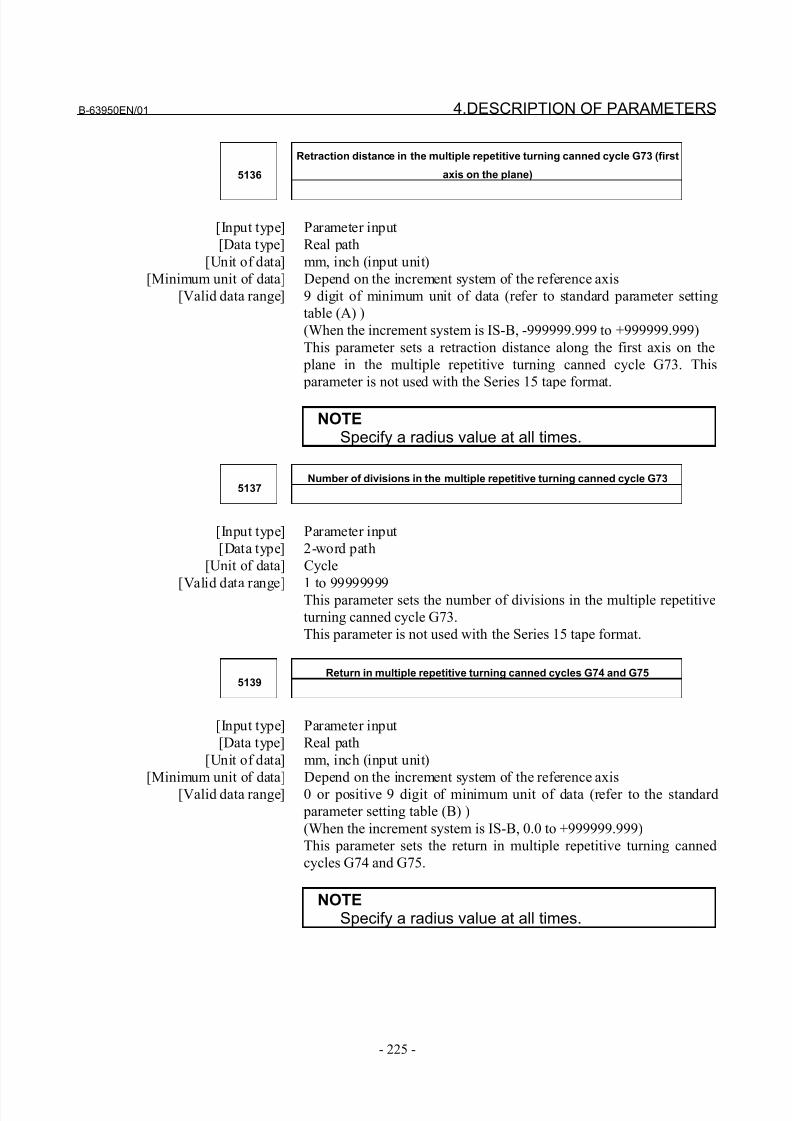
8/21/2019 30i Parameter Manual
http://slidepdf.com/reader/full/30i-parameter-manual 237/493
B-63950EN/01 4.DESCRIPTION OF PARAMETERS
- 225 -
Retraction distance in the multiple repetitive turning canned cycle G73 (first
axis on the plane)5136
[Input type] Parameter input
[Data type] Real path
[Unit of data] mm, inch (input unit)
[Minimum unit of data] Depend on the increment system of the reference axis
[Valid data range] 9 digit of minimum unit of data (refer to standard parameter setting
table (A) )
(When the increment system is IS-B, -999999.999 to +999999.999)
This parameter sets a retraction distance along the first axis on the
plane in the multiple repetitive turning canned cycle G73. This
parameter is not used with the Series 15 tape format.
NOTESpecify a radius value at all times.
Number of divisions in the multiple repetitive turning canned cycle G735137
[Input type] Parameter input
[Data type] 2-word path
[Unit of data] Cycle
[Valid data range] 1 to 99999999This parameter sets the number of divisions in the multiple repetitive
turning canned cycle G73.
This parameter is not used with the Series 15 tape format.
Return in multiple repetitive turning canned cycles G74 and G755139
[Input type] Parameter input
[Data type] Real path
[Unit of data] mm, inch (input unit)
[Minimum unit of data] Depend on the increment system of the reference axis
[Valid data range] 0 or positive 9 digit of minimum unit of data (refer to the standard
parameter setting table (B) )
(When the increment system is IS-B, 0.0 to +999999.999)
This parameter sets the return in multiple repetitive turning canned
cycles G74 and G75.
NOTESpecify a radius value at all times.
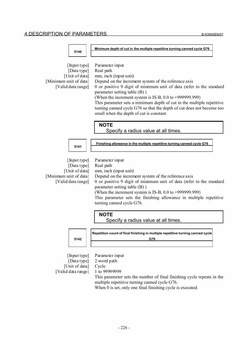
8/21/2019 30i Parameter Manual
http://slidepdf.com/reader/full/30i-parameter-manual 238/493
4.DESCRIPTION OF PARAMETERS B-63950EN/01
- 226 -
Minimum depth of cut in the multiple repetitive turning canned cycle G765140
[Input type] Parameter input
[Data type] Real path
[Unit of data] mm, inch (input unit)
[Minimum unit of data] Depend on the increment system of the reference axis
[Valid data range] 0 or positive 9 digit of minimum unit of data (refer to the standard
parameter setting table (B) )
(When the increment system is IS-B, 0.0 to +999999.999)
This parameter sets a minimum depth of cut in the multiple repetitive
turning canned cycle G76 so that the depth of cut does not become too
small when the depth of cut is constant.
NOTESpecify a radius value at all times.
Finishing allowance in the multiple repetitive turning canned cycle G765141
[Input type] Parameter input
[Data type] Real path
[Unit of data] mm, inch (input unit)
[Minimum unit of data] Depend on the increment system of the reference axis
[Valid data range] 0 or positive 9 digit of minimum unit of data (refer to the standard
parameter setting table (B) )
(When the increment system is IS-B, 0.0 to +999999.999)
This parameter sets the finishing allowance in multiple repetitive
turning canned cycle G76.
NOTESpecify a radius value at all times.
Repetition count of final finishing in multiple repetitive turning canned cycle
G765142
[Input type] Parameter input
[Data type] 2-word path
[Unit of data] Cycle
[Valid data range] 1 to 99999999
This parameter sets the number of final finishing cycle repeats in the
multiple repetitive turning canned cycle G76.
When 0 is set, only one final finishing cycle is executed.
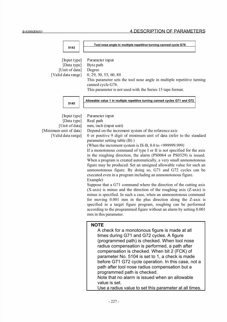
8/21/2019 30i Parameter Manual
http://slidepdf.com/reader/full/30i-parameter-manual 239/493
B-63950EN/01 4.DESCRIPTION OF PARAMETERS
- 227 -
Tool nose angle in multiple repetitive turning canned cycle G765143
[Input type] Parameter input
[Data type] Byte path
[Unit of data] Degree
[Valid data range] 0, 29, 30, 55, 60, 80
This parameter sets the tool nose angle in multiple repetitive turning
canned cycle G76.
This parameter is not used with the Series 15 tape format.
Allowable value 1 in multiple repetitive turning canned cycles G71 and G725145
[Input type] Parameter input
[Data type] Real path
[Unit of data] mm, inch (input unit)
[Minimum unit of data] Depend on the increment system of the reference axis
[Valid data range] 0 or positive 9 digit of minimum unit of data (refer to the standard
parameter setting table (B) )
(When the increment system is IS-B, 0.0 to +999999.999)
If a monotonous command of type I or II is not specified for the axis
in the roughing direction, the alarm (PS0064 or PS0329) is issued.
When a program is created automatically, a very small unmonotonous
figure may be produced. Set an unsigned allowable value for such an
unmonotonous figure. By doing so, G71 and G72 cycles can beexecuted even in a program including an unmonotonous figure.
Example)
Suppose that a G71 command where the direction of the cutting axis
(X-axis) is minus and the direction of the roughing axis (Z-axis) is
minus is specified. In such a case, when an unmonotonous command
for moving 0.001 mm in the plus direction along the Z-axis is
specified in a target figure program, roughing can be performed
according to the programmed figure without an alarm by setting 0.001
mm in this parameter.
NOTE A check for a monotonous figure is made at alltimes during G71 and G72 cycles. A figure(programmed path) is checked. When tool noseradius compensation is performed, a path after compensation is checked. When bit 2 (FCK) of parameter No. 5104 is set to 1, a check is madebefore G71 G72 cycle operation. In this case, not apath after tool nose radius compensation but aprogrammed path is checked.Note that no alarm is issued when an allowable
value is set.Use a radius value to set this parameter at all times.
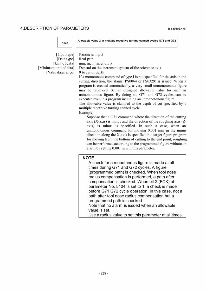
8/21/2019 30i Parameter Manual
http://slidepdf.com/reader/full/30i-parameter-manual 240/493
4.DESCRIPTION OF PARAMETERS B-63950EN/01
- 228 -
Allowable value 2 in multiple repetitive turning canned cycles G71 and G725146
[Input type] Parameter input
[Data type] Real path
[Unit of data] mm, inch (input unit)
[Minimum unit of data] Depend on the increment system of the reference axis
[Valid data range] 0 to cut of depth
If a monotonous command of type I is not specified for the axis in the
cutting direction, the alarm (PS0064 or PS0329) is issued. When a
program is created automatically, a very small unmonotonous figure
may be produced. Set an unsigned allowable value for such an
unmonotonous figure. By doing so, G71 and G72 cycles can be
executed even in a program including an unmonotonous figure.
The allowable value is clamped to the depth of cut specified by amultiple repetitive turning canned cycle.
Example)
Suppose that a G71 command where the direction of the cutting
axis (X-axis) is minus and the direction of the roughing axis (Z-
axis) is minus is specified. In such a case, when an
unmonotonous command for moving 0.001 mm in the minus
direction along the X-axis is specified in a target figure program
for moving from the bottom of cutting to the end point, roughing
can be performed according to the programmed figure without an
alarm by setting 0.001 mm in this parameter.
NOTE A check for a monotonous figure is made at alltimes during G71 and G72 cycles. A figure(programmed path) is checked. When tool noseradius compensation is performed, a path after compensation is checked. When bit 2 (FCK) of parameter No. 5104 is set to 1, a check is madebefore G71 G72 cycle operation. In this case, not apath after tool nose radius compensation but aprogrammed path is checked.
Note that no alarm is issued when an allowablevalue is set.Use a radius value to set this parameter at all times.
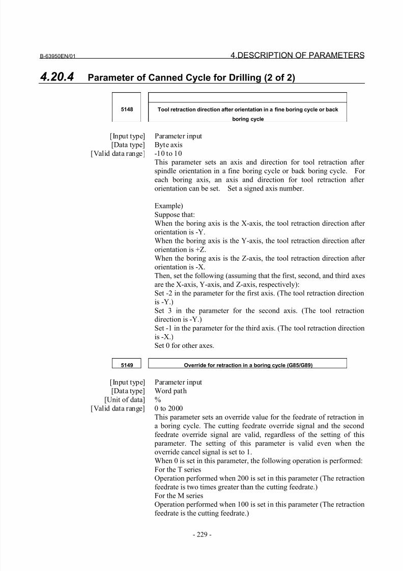
8/21/2019 30i Parameter Manual
http://slidepdf.com/reader/full/30i-parameter-manual 241/493
B-63950EN/01 4.DESCRIPTION OF PARAMETERS
- 229 -
4.20.4 Parameter of Canned Cycle for Drilling (2 of 2)
5148 Tool retraction direction after orientation in a fine boring cycle or back
boring cycle
[Input type] Parameter input
[Data type] Byte axis
[Valid data range] -10 to 10
This parameter sets an axis and direction for tool retraction after
spindle orientation in a fine boring cycle or back boring cycle. For
each boring axis, an axis and direction for tool retraction after
orientation can be set. Set a signed axis number.
Example)
Suppose that:
When the boring axis is the X-axis, the tool retraction direction after
orientation is -Y.
When the boring axis is the Y-axis, the tool retraction direction after
orientation is +Z.
When the boring axis is the Z-axis, the tool retraction direction after
orientation is -X.
Then, set the following (assuming that the first, second, and third axes
are the X-axis, Y-axis, and Z-axis, respectively):
Set -2 in the parameter for the first axis. (The tool retraction direction
is -Y.)Set 3 in the parameter for the second axis. (The tool retraction
direction is -Y.)
Set -1 in the parameter for the third axis. (The tool retraction direction
is -X.)
Set 0 for other axes.
5149 Override for retraction in a boring cycle (G85/G89)
[Input type] Parameter input
[Data type] Word path
[Unit of data] %[Valid data range] 0 to 2000
This parameter sets an override value for the feedrate of retraction in
a boring cycle. The cutting feedrate override signal and the second
feedrate override signal are valid, regardless of the setting of this
parameter. The setting of this parameter is valid even when the
override cancel signal is set to 1.
When 0 is set in this parameter, the following operation is performed:
For the T series
Operation performed when 200 is set in this parameter (The retraction
feedrate is two times greater than the cutting feedrate.)
For the M series
Operation performed when 100 is set in this parameter (The retraction
feedrate is the cutting feedrate.)
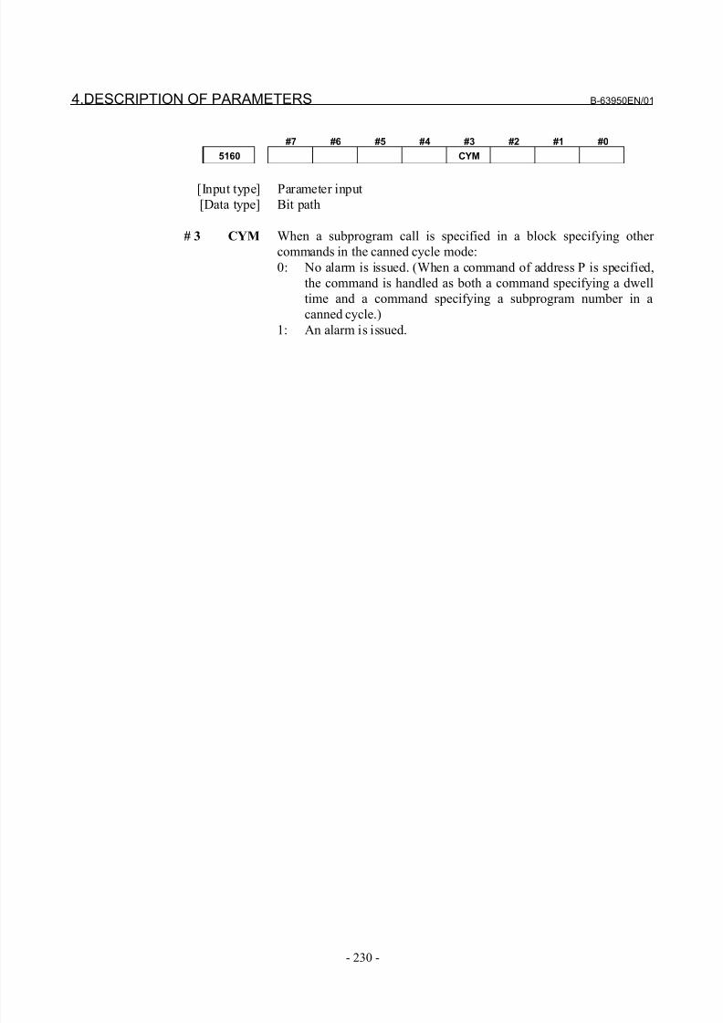
8/21/2019 30i Parameter Manual
http://slidepdf.com/reader/full/30i-parameter-manual 242/493
4.DESCRIPTION OF PARAMETERS B-63950EN/01
- 230 -
#7 #6 #5 #4 #3 #2 #1 #0
5160 CYM
[Input type] Parameter input
[Data type] Bit path
# 3 CYM When a subprogram call is specified in a block specifying other
commands in the canned cycle mode:
0: No alarm is issued. (When a command of address P is specified,
the command is handled as both a command specifying a dwell
time and a command specifying a subprogram number in a
canned cycle.)
1: An alarm is issued.
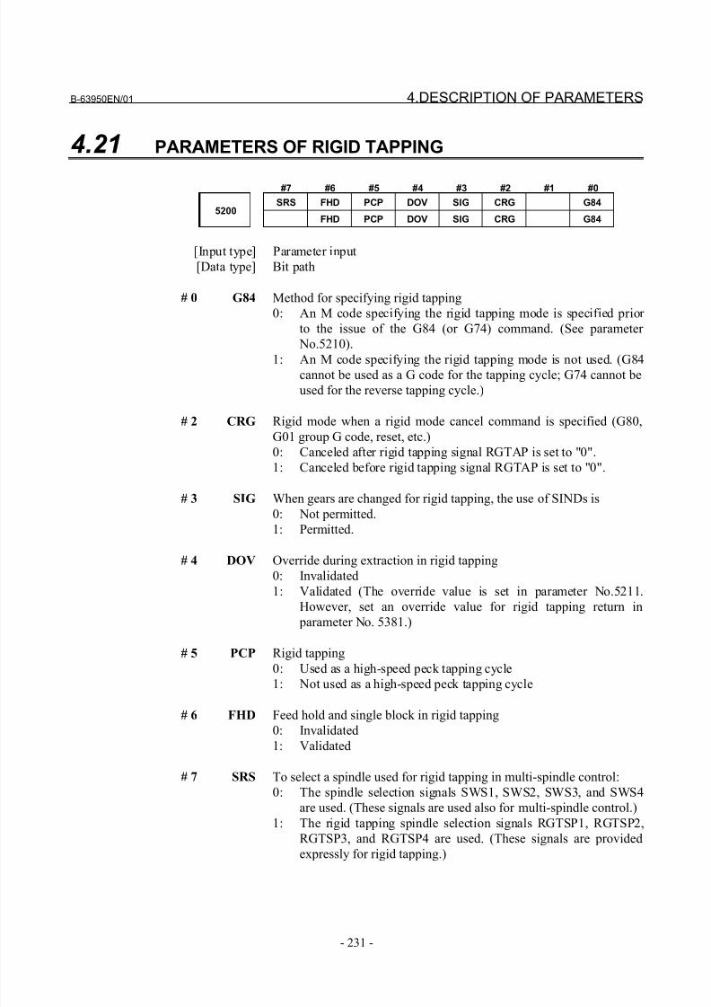
8/21/2019 30i Parameter Manual
http://slidepdf.com/reader/full/30i-parameter-manual 243/493
B-63950EN/01 4.DESCRIPTION OF PARAMETERS
- 231 -
4.21 PARAMETERS OF RIGID TAPPING
#7 #6 #5 #4 #3 #2 #1 #0
SRS FHD PCP DOV SIG CRG G845200
FHD PCP DOV SIG CRG G84
[Input type] Parameter input
[Data type] Bit path
# 0 G84 Method for specifying rigid tapping
0: An M code specifying the rigid tapping mode is specified prior
to the issue of the G84 (or G74) command. (See parameter
No.5210).
1: An M code specifying the rigid tapping mode is not used. (G84
cannot be used as a G code for the tapping cycle; G74 cannot be
used for the reverse tapping cycle.)
# 2 CRG Rigid mode when a rigid mode cancel command is specified (G80,
G01 group G code, reset, etc.)
0: Canceled after rigid tapping signal RGTAP is set to "0".
1: Canceled before rigid tapping signal RGTAP is set to "0".
# 3 SIG When gears are changed for rigid tapping, the use of SINDs is
0: Not permitted.
1: Permitted.
# 4 DOV Override during extraction in rigid tapping
0: Invalidated
1: Validated (The override value is set in parameter No.5211.
However, set an override value for rigid tapping return in
parameter No. 5381.)
# 5 PCP Rigid tapping
0: Used as a high-speed peck tapping cycle
1: Not used as a high-speed peck tapping cycle
# 6 FHD Feed hold and single block in rigid tapping
0: Invalidated
1: Validated
# 7 SRS To select a spindle used for rigid tapping in multi-spindle control:
0: The spindle selection signals SWS1, SWS2, SWS3, and SWS4
are used. (These signals are used also for multi-spindle control.)
1: The rigid tapping spindle selection signals RGTSP1, RGTSP2,
RGTSP3, and RGTSP4 are used. (These signals are provided
expressly for rigid tapping.)
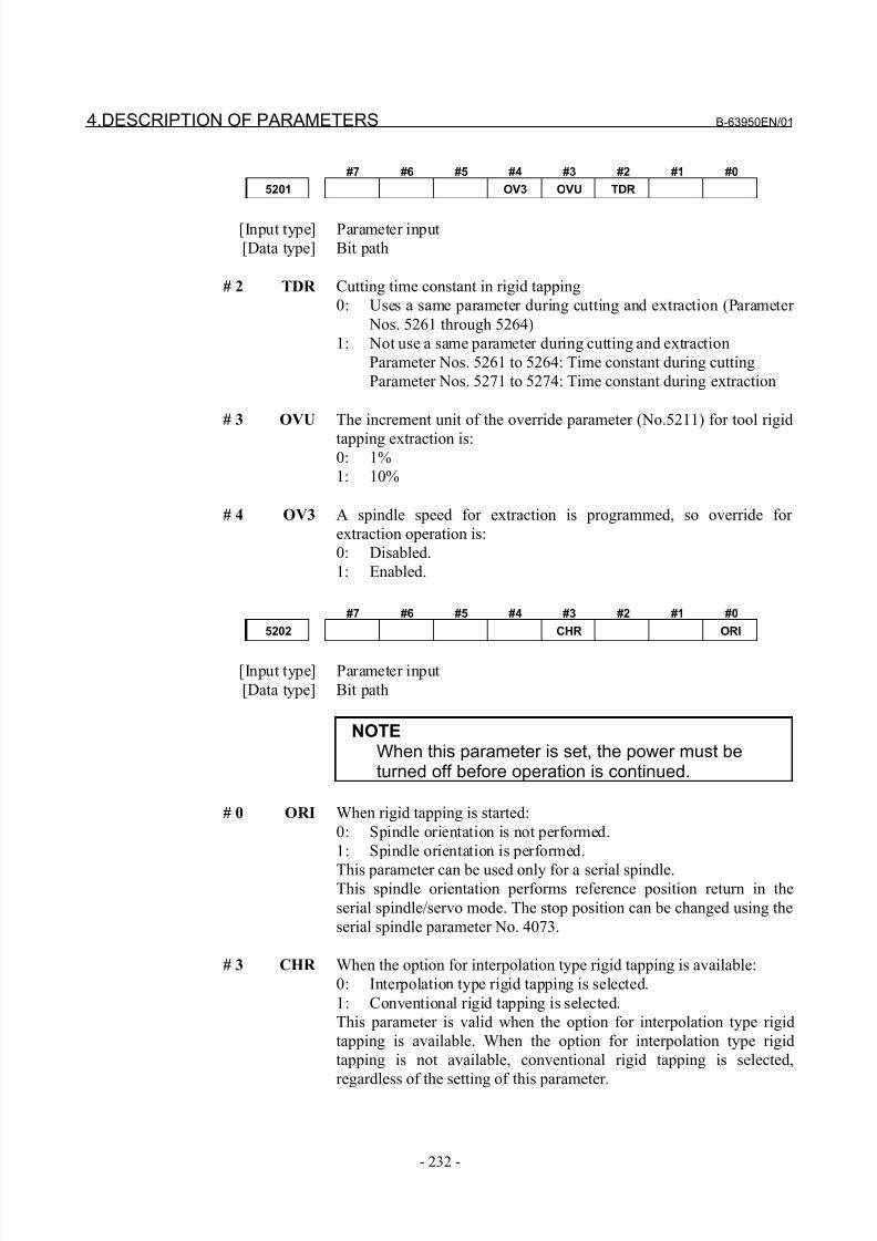
8/21/2019 30i Parameter Manual
http://slidepdf.com/reader/full/30i-parameter-manual 244/493
4.DESCRIPTION OF PARAMETERS B-63950EN/01
- 232 -
#7 #6 #5 #4 #3 #2 #1 #0
5201 OV3 OVU TDR
[Input type] Parameter input
[Data type] Bit path
# 2 TDR Cutting time constant in rigid tapping
0: Uses a same parameter during cutting and extraction (Parameter
Nos. 5261 through 5264)
1: Not use a same parameter during cutting and extraction
Parameter Nos. 5261 to 5264: Time constant during cutting
Parameter Nos. 5271 to 5274: Time constant during extraction
# 3 OVU The increment unit of the override parameter (No.5211) for tool rigid
tapping extraction is:0: 1%
1: 10%
# 4 OV3 A spindle speed for extraction is programmed, so override for
extraction operation is:
0: Disabled.
1: Enabled.
#7 #6 #5 #4 #3 #2 #1 #0
5202 CHR ORI
[Input type] Parameter input
[Data type] Bit path
NOTEWhen this parameter is set, the power must beturned off before operation is continued.
# 0 ORI When rigid tapping is started:
0: Spindle orientation is not performed.
1: Spindle orientation is performed.
This parameter can be used only for a serial spindle.This spindle orientation performs reference position return in the
serial spindle/servo mode. The stop position can be changed using the
serial spindle parameter No. 4073.
# 3 CHR When the option for interpolation type rigid tapping is available:
0: Interpolation type rigid tapping is selected.
1: Conventional rigid tapping is selected.
This parameter is valid when the option for interpolation type rigid
tapping is available. When the option for interpolation type rigid
tapping is not available, conventional rigid tapping is selected,
regardless of the setting of this parameter.
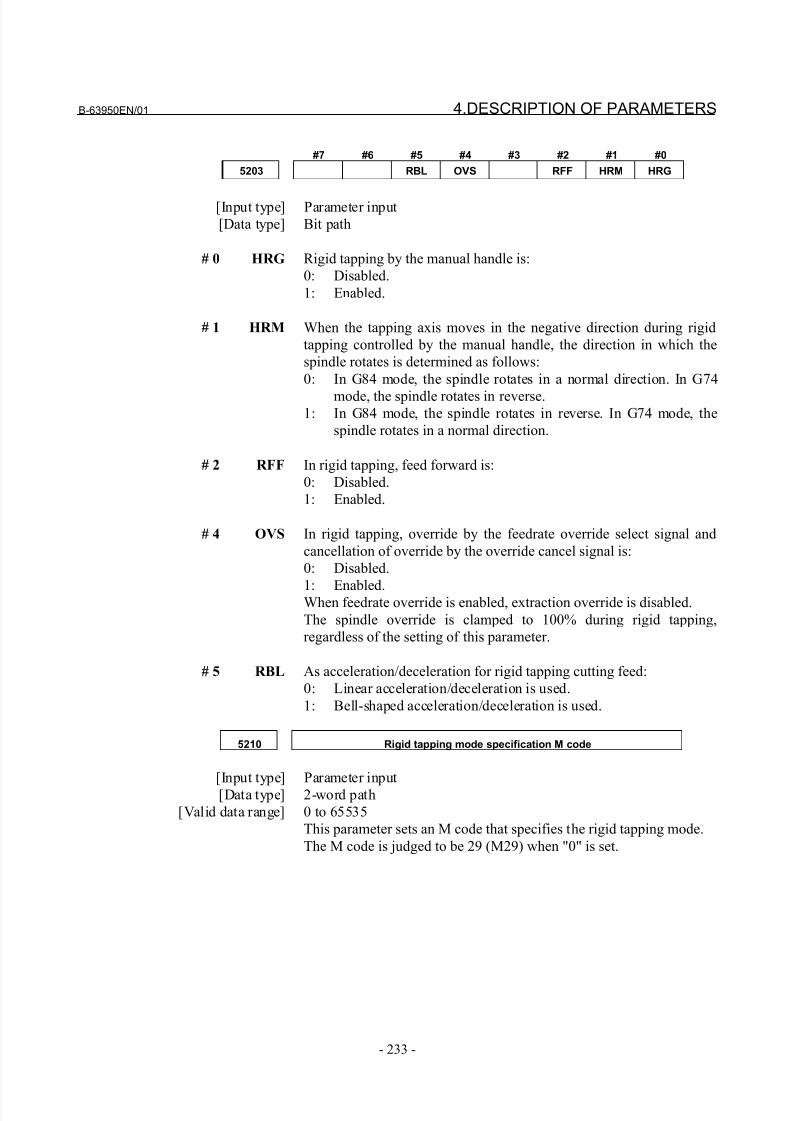
8/21/2019 30i Parameter Manual
http://slidepdf.com/reader/full/30i-parameter-manual 245/493
B-63950EN/01 4.DESCRIPTION OF PARAMETERS
- 233 -
#7 #6 #5 #4 #3 #2 #1 #0
5203 RBL OVS RFF HRM HRG
[Input type] Parameter input
[Data type] Bit path
# 0 HRG Rigid tapping by the manual handle is:
0: Disabled.
1: Enabled.
# 1 HRM When the tapping axis moves in the negative direction during rigid
tapping controlled by the manual handle, the direction in which the
spindle rotates is determined as follows:
0: In G84 mode, the spindle rotates in a normal direction. In G74
mode, the spindle rotates in reverse.1: In G84 mode, the spindle rotates in reverse. In G74 mode, the
spindle rotates in a normal direction.
# 2 RFF In rigid tapping, feed forward is:
0: Disabled.
1: Enabled.
# 4 OVS In rigid tapping, override by the feedrate override select signal and
cancellation of override by the override cancel signal is:
0: Disabled.
1: Enabled.When feedrate override is enabled, extraction override is disabled.
The spindle override is clamped to 100% during rigid tapping,
regardless of the setting of this parameter.
# 5 RBL As acceleration/deceleration for rigid tapping cutting feed:
0: Linear acceleration/deceleration is used.
1: Bell-shaped acceleration/deceleration is used.
5210 Rigid tapping mode specification M code
[Input type] Parameter input
[Data type] 2-word path
[Valid data range] 0 to 65535
This parameter sets an M code that specifies the rigid tapping mode.
The M code is judged to be 29 (M29) when "0" is set.
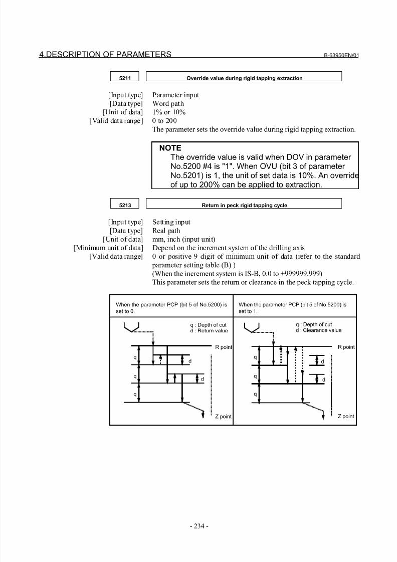
8/21/2019 30i Parameter Manual
http://slidepdf.com/reader/full/30i-parameter-manual 246/493
4.DESCRIPTION OF PARAMETERS B-63950EN/01
- 234 -
5211 Override value during rigid tapping extraction
[Input type] Parameter input[Data type] Word path
[Unit of data] 1% or 10%
[Valid data range] 0 to 200
The parameter sets the override value during rigid tapping extraction.
NOTEThe override value is valid when DOV in parameter No.5200 #4 is "1". When OVU (bit 3 of parameter No.5201) is 1, the unit of set data is 10%. An overrideof up to 200% can be applied to extraction.
5213 Return in peck rigid tapping cycle
[Input type] Setting input
[Data type] Real path
[Unit of data] mm, inch (input unit)
[Minimum unit of data] Depend on the increment system of the drilling axis
[Valid data range] 0 or positive 9 digit of minimum unit of data (refer to the standard
parameter setting table (B) )
(When the increment system is IS-B, 0.0 to +999999.999)
This parameter sets the return or clearance in the peck tapping cycle.
When the parameter PCP (bit 5 of No.5200) isset to 0.
When the parameter PCP (bit 5 of No.5200) isset to 1.
q : Depth of cutd : Return value
R point
Z point
q : Depth of cutd : Clearance value
R point
Z point
qd
dq
q
d
d
q
q
q
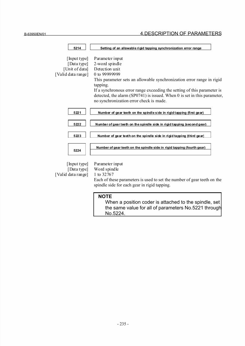
8/21/2019 30i Parameter Manual
http://slidepdf.com/reader/full/30i-parameter-manual 247/493
B-63950EN/01 4.DESCRIPTION OF PARAMETERS
- 235 -
5214 Setting of an allowable rigid tapping synchronization error range
[Input type] Parameter input[Data type] 2-word spindle
[Unit of data] Detection unit
[Valid data range] 0 to 99999999
This parameter sets an allowable synchronization error range in rigid
tapping.
If a synchronous error range exceeding the setting of this parameter is
detected, the alarm (SP0741) is issued. When 0 is set in this parameter,
no synchronization error check is made.
5221 Number of gear teeth on the spindle side in rigid tapping (first gear)
5222 Number of gear teeth on the spindle side in rigid tapping (second gear)
5223 Number of gear teeth on the spindle side in rigid tapping (third gear)
Number of gear teeth on the spindle side in rigid tapping (fourth gear)5224
[Input type] Parameter input
[Data type] Word spindle
[Valid data range] 1 to 32767
Each of these parameters is used to set the number of gear teeth on thespindle side for each gear in rigid tapping.
NOTEWhen a position coder is attached to the spindle, setthe same value for all of parameters No.5221 throughNo.5224.

8/21/2019 30i Parameter Manual
http://slidepdf.com/reader/full/30i-parameter-manual 248/493
4.DESCRIPTION OF PARAMETERS B-63950EN/01
- 236 -
5231 Number of gear teeth on the position coder side in rigid tapping (first gear)
5232 Number of gear teeth on the position coder side in rigid tapping (secondgear)
5233 Number of gear teeth on the position coder side in rigid tapping (third gear)
Number of gear teeth on the position coder side in rigid tapping (fourth gear)5234
[Input type] Parameter input
[Data type] Word spindle
[Valid data range] 1 to 32767
Each of these parameters is used to set the number of gear teeth on the position coder side for each gear in rigid tapping.
NOTEWhen a position coder is attached to the spindle, setthe same value for all of parameters No.5231 throughNo.5234.
5241 Maximum spindle speed in rigid tapping (first gear)
5242 Maximum spindle speed in rigid tapping (second gear)
5243 Maximum spindle speed in rigid tapping (third gear)
Maximum spindle speed in rigid tapping (fourth gear)5244
[Input type] Parameter input
[Data type] 2-word spindle
[Unit of data] min-1
[Valid data range] 0 to 9999
Spindle position coder gear ratio
1 : 1 0 to 7400
1 : 2 0 to 9999
1 : 4 0 to 9999
1 : 8 0 to 9999
Each of these parameters is used to set a maximum spindle speed for
each gear in rigid tapping.
Set the same value for both parameter No.5241 and parameter
No.5243 for a one-stage gear system. For a two-stage gear system, set
the same value as set in parameter No. 5242 in parameter No. 5243.
Otherwise, alarm PS0200 will be issued. This applies to the M series.
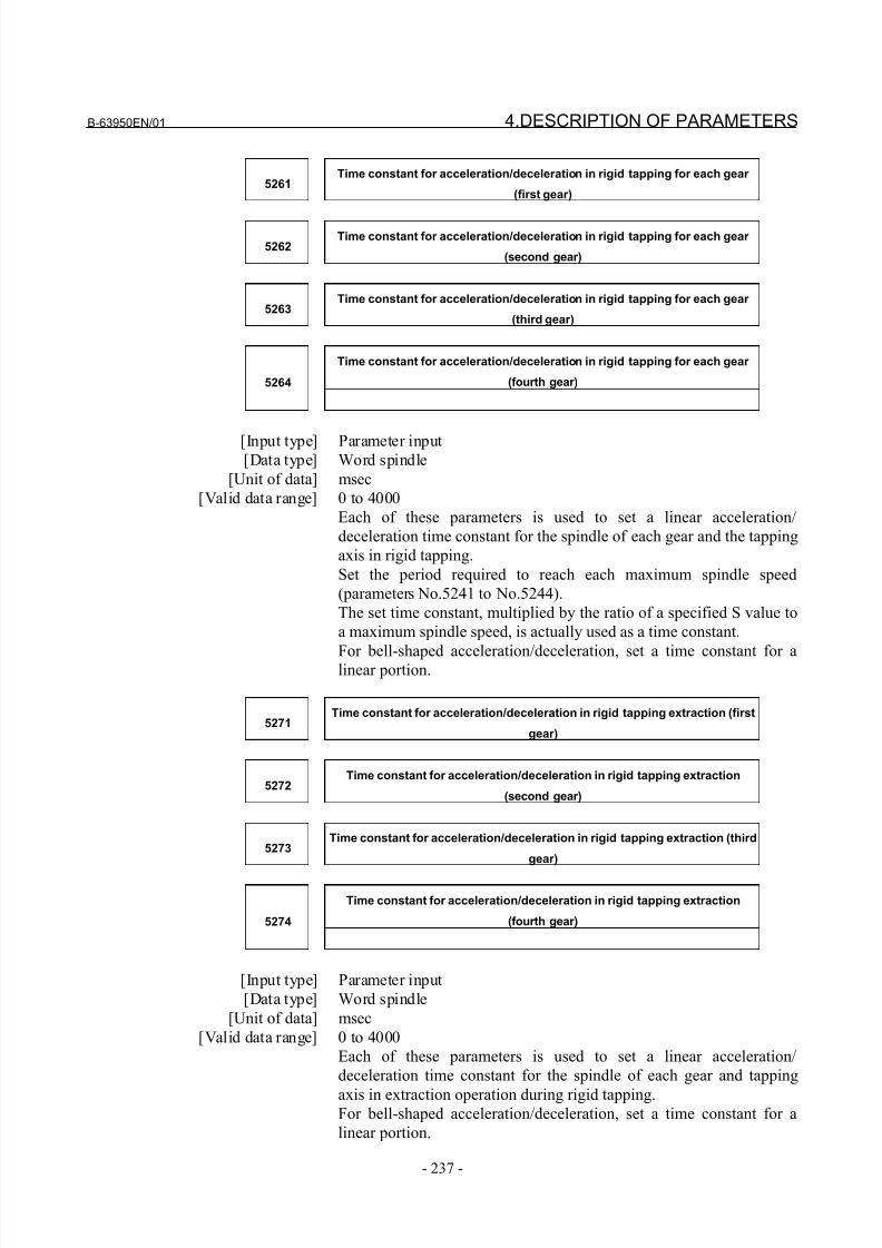
8/21/2019 30i Parameter Manual
http://slidepdf.com/reader/full/30i-parameter-manual 249/493
B-63950EN/01 4.DESCRIPTION OF PARAMETERS
- 237 -
5261Time constant for acceleration/deceleration in rigid tapping for each gear
(first gear)
5262Time constant for acceleration/deceleration in rigid tapping for each gear
(second gear)
5263Time constant for acceleration/deceleration in rigid tapping for each gear
(third gear)
Time constant for acceleration/deceleration in rigid tapping for each gear
(fourth gear)5264
[Input type] Parameter input[Data type] Word spindle
[Unit of data] msec
[Valid data range] 0 to 4000
Each of these parameters is used to set a linear acceleration/
deceleration time constant for the spindle of each gear and the tapping
axis in rigid tapping.
Set the period required to reach each maximum spindle speed
(parameters No.5241 to No.5244).
The set time constant, multiplied by the ratio of a specified S value to
a maximum spindle speed, is actually used as a time constant.
For bell-shaped acceleration/deceleration, set a time constant for alinear portion.
5271Time constant for acceleration/deceleration in rigid tapping extraction (first
gear)
5272Time constant for acceleration/deceleration in rigid tapping extraction
(second gear)
5273Time constant for acceleration/deceleration in rigid tapping extraction (third
gear)
Time constant for acceleration/deceleration in rigid tapping extraction
(fourth gear)5274
[Input type] Parameter input
[Data type] Word spindle
[Unit of data] msec
[Valid data range] 0 to 4000
Each of these parameters is used to set a linear acceleration/
deceleration time constant for the spindle of each gear and tapping
axis in extraction operation during rigid tapping.For bell-shaped acceleration/deceleration, set a time constant for a
linear portion.
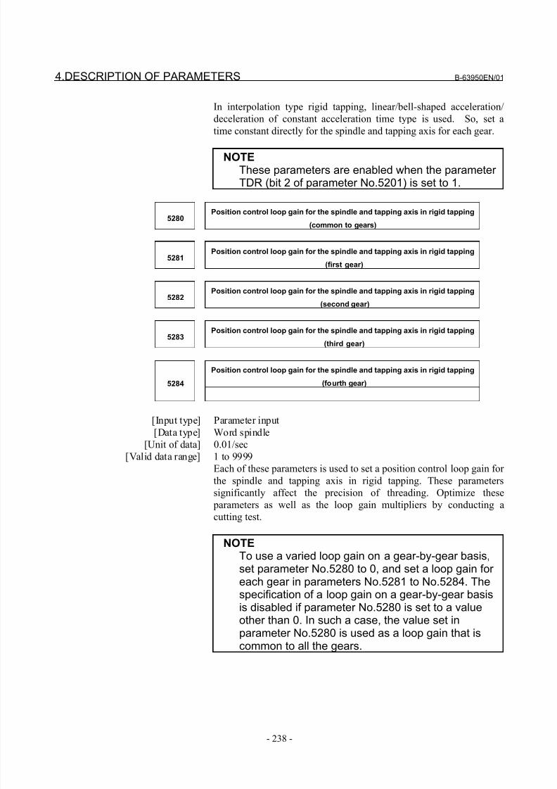
8/21/2019 30i Parameter Manual
http://slidepdf.com/reader/full/30i-parameter-manual 250/493
4.DESCRIPTION OF PARAMETERS B-63950EN/01
- 238 -
In interpolation type rigid tapping, linear/bell-shaped acceleration/
deceleration of constant acceleration time type is used. So, set a
time constant directly for the spindle and tapping axis for each gear.
NOTEThese parameters are enabled when the parameter TDR (bit 2 of parameter No.5201) is set to 1.
5280Position control loop gain for the spindle and tapping axis in rigid tapping
(common to gears)
5281Position control loop gain for the spindle and tapping axis in rigid tapping
(first gear)
5282Position control loop gain for the spindle and tapping axis in rigid tapping
(second gear)
5283Position control loop gain for the spindle and tapping axis in rigid tapping
(third gear)
Position control loop gain for the spindle and tapping axis in rigid tapping
(fourth gear)5284
[Input type] Parameter input
[Data type] Word spindle
[Unit of data] 0.01/sec
[Valid data range] 1 to 9999
Each of these parameters is used to set a position control loop gain for
the spindle and tapping axis in rigid tapping. These parameters
significantly affect the precision of threading. Optimize these
parameters as well as the loop gain multipliers by conducting a
cutting test.
NOTE
To use a varied loop gain on a gear-by-gear basis,set parameter No.5280 to 0, and set a loop gain for each gear in parameters No.5281 to No.5284. Thespecification of a loop gain on a gear-by-gear basisis disabled if parameter No.5280 is set to a valueother than 0. In such a case, the value set inparameter No.5280 is used as a loop gain that iscommon to all the gears.
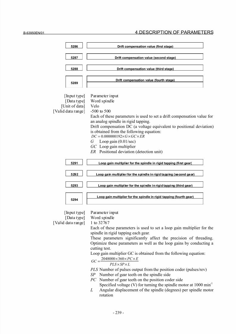
8/21/2019 30i Parameter Manual
http://slidepdf.com/reader/full/30i-parameter-manual 251/493
B-63950EN/01 4.DESCRIPTION OF PARAMETERS
- 239 -
5286 Drift compensation value (first stage)
5287 Drift compensation value (second stage)
5288 Drift compensation value (third stage)
Drift compensation value (fourth stage)5289
[Input type] Parameter input
[Data type] Word spindle
[Unit of data] Velo
[Valid data range] -500 to 500
Each of these parameters is used to set a drift compensation value for an analog spindle in rigid tapping.
Drift compensation DC (a voltage equivalent to positional deviation)
is obtained from the following equation: ERGC G DC ×××= 000000192.0
G Loop gain (0.01/sec)
GC Loop gain multiplier
ER Positional deviation (detection unit)
5291 Loop gain multiplier for the spindle in rigid tapping (first gear)
5292 Loop gain multiplier for the spindle in rigid tapping (second gear)
5293 Loop gain multiplier for the spindle in rigid tapping (third gear)
Loop gain multiplier for the spindle in rigid tapping (fourth gear)5294
[Input type] Parameter input
[Data type] Word spindle
[Valid data range] 1 to 32767
Each of these parameters is used to set a loop gain multiplier for the
spindle in rigid tapping each gear.These parameters significantly affect the precision of threading.
Optimize these parameters as well as the loop gains by conducting a
cutting test.
Loop gain multiplier GC is obtained from the following equation:
LSP PLS
E PC GC
××
×××=
3602048000
PLS Number of pulses output from the position coder (pulses/rev)
SP Number of gear teeth on the spindle side
PC Number of gear teeth on the position coder side
Specified voltage (V) for turning the spindle motor at 1000 min-1
L Angular displacement of the spindle (degrees) per spindle motor
rotation
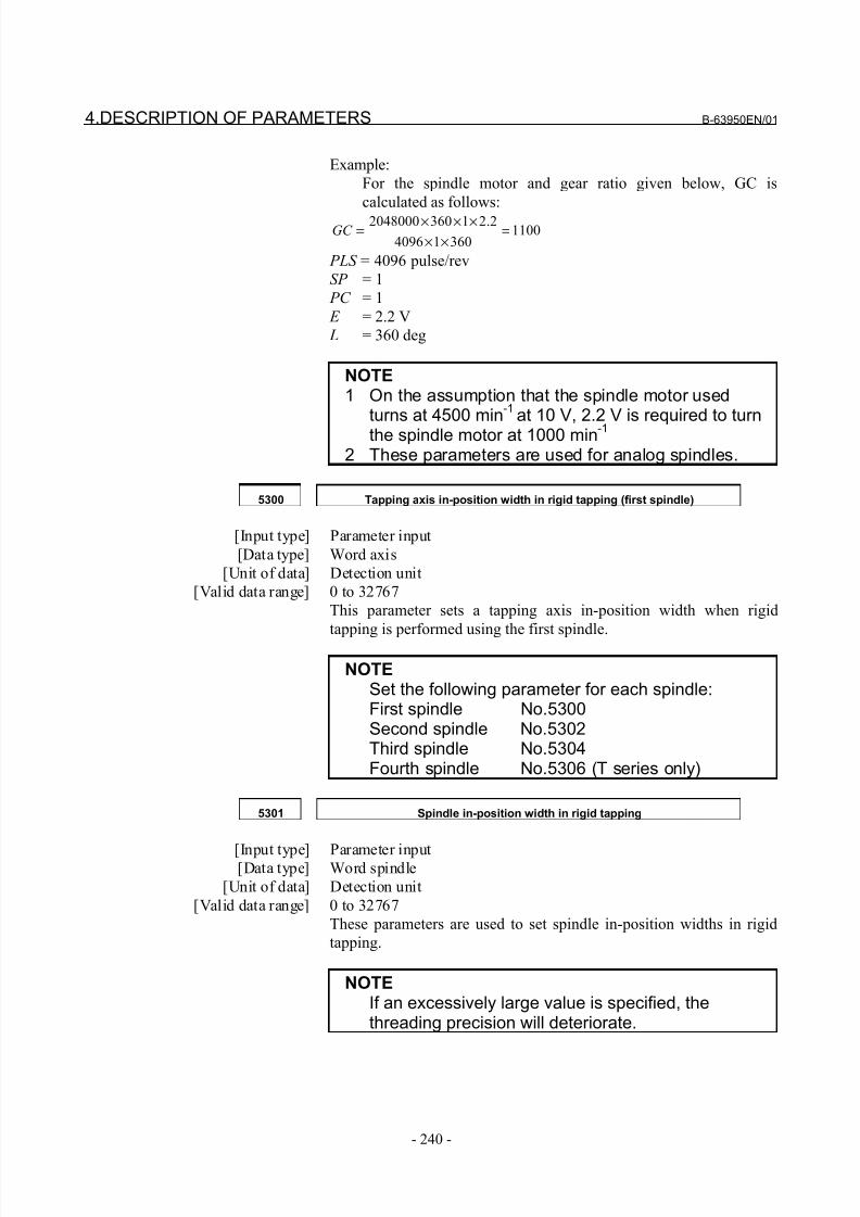
8/21/2019 30i Parameter Manual
http://slidepdf.com/reader/full/30i-parameter-manual 252/493
4.DESCRIPTION OF PARAMETERS B-63950EN/01
- 240 -
Example:
For the spindle motor and gear ratio given below, GC is
calculated as follows:
110036014096
2.213602048000=
×××××
=GC
PLS = 4096 pulse/rev
SP = 1
PC = 1
E = 2.2 V
L = 360 deg
NOTE1 On the assumption that the spindle motor used
turns at 4500 min-1
at 10 V, 2.2 V is required to turnthe spindle motor at 1000 min-1
2 These parameters are used for analog spindles.
5300 Tapping axis in-position width in rigid tapping (first spindle)
[Input type] Parameter input
[Data type] Word axis
[Unit of data] Detection unit
[Valid data range] 0 to 32767
This parameter sets a tapping axis in-position width when rigid
tapping is performed using the first spindle.
NOTESet the following parameter for each spindle:First spindle No.5300Second spindle No.5302Third spindle No.5304Fourth spindle No.5306 (T series only)
5301 Spindle in-position width in rigid tapping
[Input type] Parameter input[Data type] Word spindle
[Unit of data] Detection unit
[Valid data range] 0 to 32767
These parameters are used to set spindle in-position widths in rigid
tapping.
NOTEIf an excessively large value is specified, thethreading precision will deteriorate.
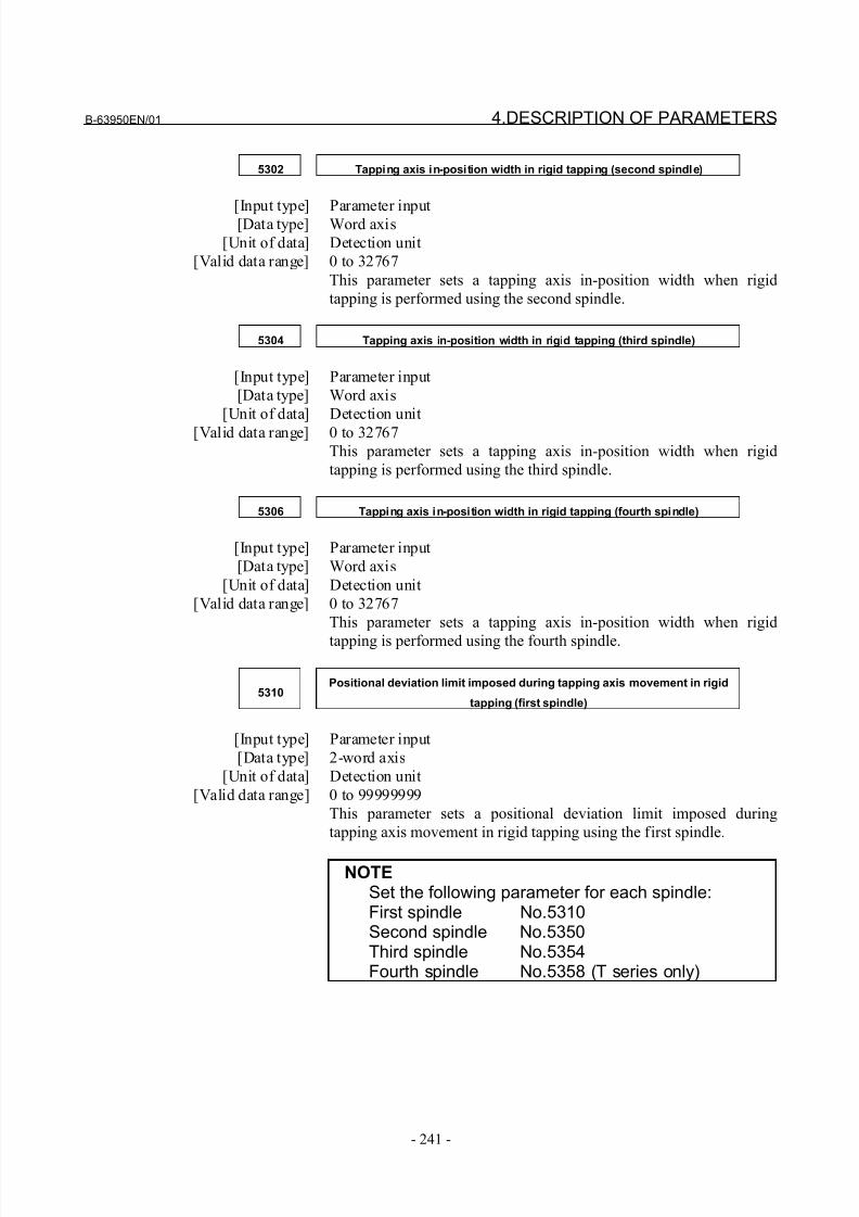
8/21/2019 30i Parameter Manual
http://slidepdf.com/reader/full/30i-parameter-manual 253/493
B-63950EN/01 4.DESCRIPTION OF PARAMETERS
- 241 -
5302 Tapping axis in-position width in rigid tapping (second spindle)
[Input type] Parameter input[Data type] Word axis
[Unit of data] Detection unit
[Valid data range] 0 to 32767
This parameter sets a tapping axis in-position width when rigid
tapping is performed using the second spindle.
5304 Tapping axis in-position width in rigid tapping (third spindle)
[Input type] Parameter input
[Data type] Word axis
[Unit of data] Detection unit
[Valid data range] 0 to 32767
This parameter sets a tapping axis in-position width when rigid
tapping is performed using the third spindle.
5306 Tapping axis in-position width in rigid tapping (fourth spindle)
[Input type] Parameter input
[Data type] Word axis
[Unit of data] Detection unit
[Valid data range] 0 to 32767
This parameter sets a tapping axis in-position width when rigid
tapping is performed using the fourth spindle.
5310Positional deviation limit imposed during tapping axis movement in rigid
tapping (first spindle)
[Input type] Parameter input
[Data type] 2-word axis
[Unit of data] Detection unit
[Valid data range] 0 to 99999999
This parameter sets a positional deviation limit imposed during
tapping axis movement in rigid tapping using the first spindle.
NOTESet the following parameter for each spindle:First spindle No.5310Second spindle No.5350Third spindle No.5354Fourth spindle No.5358 (T series only)
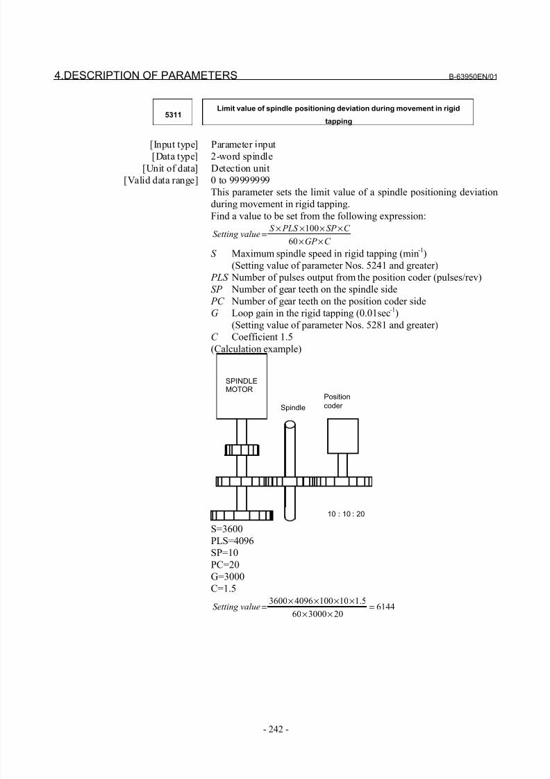
8/21/2019 30i Parameter Manual
http://slidepdf.com/reader/full/30i-parameter-manual 254/493
4.DESCRIPTION OF PARAMETERS B-63950EN/01
- 242 -
5311Limit value of spindle positioning deviation during movement in rigid
tapping
[Input type] Parameter input
[Data type] 2-word spindle
[Unit of data] Detection unit
[Valid data range] 0 to 99999999
This parameter sets the limit value of a spindle positioning deviation
during movement in rigid tapping.
Find a value to be set from the following expression:
C GP
C SP PLS S valueSetting
××××××
=60
100
S Maximum spindle speed in rigid tapping (min-1
)
(Setting value of parameter Nos. 5241 and greater)
PLS Number of pulses output from the position coder (pulses/rev)
SP Number of gear teeth on the spindle side
PC Number of gear teeth on the position coder side
G Loop gain in the rigid tapping (0.01sec-1
)
(Setting value of parameter Nos. 5281 and greater)
C Coefficient 1.5
(Calculation example)
10 : 10 : 20
SPINDLEMOTOR
Spindle
Position
coder
S=3600
PLS=4096SP=10
PC=20
G=3000
C=1.5
614420300060
5.11010040963600=
××
××××=valueSetting
8/21/2019 30i Parameter Manual
http://slidepdf.com/reader/full/30i-parameter-manual 255/493
B-63950EN/01 4.DESCRIPTION OF PARAMETERS
- 243 -
5312Positional deviation limit imposed while the tapping axis is stopped in rigid
tapping (first spindle)
[Input type] Parameter input
[Data type] Word axis
[Unit of data] Detection unit
[Valid data range] 0 to 32767
This parameter sets a positional deviation limit imposed while the
tapping axis is stopped in rigid tapping using the first spindle.
NOTESet the following parameter for each spindle:First spindle No.5312
Second spindle No.5352Third spindle No.5356Fourth spindle No.5360 (T series only)
5313Positional deviation limit imposed while the spindle is stopped in rigid
tapping
[Input type] Parameter input
[Data type] 2-word spindle
[Unit of data] Detection unit
[Valid data range] 0 to 99999999
This parameter is used to set a positional deviation limit imposedwhile the spindle is stopped in rigid tapping.
5321 Spindle backlash in rigid tapping (first-stage gear)
5322 Spindle backlash in rigid tapping (second-stage gear)
5323 Spindle backlash in rigid tapping (third-stage gear)
Spindle backlash in rigid tapping (fourth-stage gear)5324
[Input type] Parameter input
[Data type] Word spindle
[Unit of data] Detection unit
[Valid data range] -9999 to 9999
Each of these parameters is used to set a spindle backlash.
8/21/2019 30i Parameter Manual
http://slidepdf.com/reader/full/30i-parameter-manual 256/493
4.DESCRIPTION OF PARAMETERS B-63950EN/01
- 244 -
5350Positional deviation limit imposed during tapping axis movement in rigid
tapping (second spindle)
[Input type] Parameter input
[Data type] 2-word axis
[Unit of data] Detection unit
[Valid data range] 0 to 99999999
This parameter sets a positional deviation limit imposed during
tapping axis movement in rigid tapping using the second spindle.
5352Positional deviation limit imposed while the tapping axis is stopped in rigid
tapping (second spindle)
[Input type] Parameter input
[Data type] Word axis
[Unit of data] Detection unit
[Valid data range] 0 to 32767
This parameter is used to set a positional deviation limit imposed
while the tapping axis is stopped in rigid tapping using the second
spindle.
5354Positional deviation limit imposed during tapping axis movement in rigid
tapping (third spindle)
[Input type] Parameter input
[Data type] 2-word axis[Unit of data] Detection unit
[Valid data range] 0 to 99999999
This parameter sets a positional deviation limit imposed during
tapping axis movement in rigid tapping using the third spindle.
5356Positional deviation limit imposed while the tapping axis is stopped in rigid
tapping (third spindle)
[Input type] Parameter input
[Data type] Word axis
[Unit of data] Detection unit[Valid data range] 0 to 32767
This parameter is used to set a positional deviation limit imposed
while the tapping axis is stopped in rigid tapping using the third
spindle.
8/21/2019 30i Parameter Manual
http://slidepdf.com/reader/full/30i-parameter-manual 257/493
B-63950EN/01 4.DESCRIPTION OF PARAMETERS
- 245 -
5358Positional deviation limit imposed during tapping axis movement in rigid
tapping (fourth spindle)
[Input type] Parameter input
[Data type] 2-word axis
[Unit of data] Detection unit
[Valid data range] 0 to 99999999
This parameter sets a positional deviation limit imposed during
tapping axis movement in rigid tapping using the fourth spindle.
5360Positional deviation limit imposed while the tapping axis is stopped in rigid
tapping (fourth spindle)
[Input type] Parameter input
[Data type] Word axis
[Unit of data] Detection unit
[Valid data range] 0 to 32767
This parameter is used to set a positional deviation limit imposed
while the tapping axis is stopped in rigid tapping using the fourth
spindle.
5365Bell-shaped acceleration/deceleration time constant in rigid tapping (first-
stage gear)
5366Bell-shaped acceleration/deceleration time constant in rigid tapping
(second-stage gear)
5367Bell-shaped acceleration/deceleration time constant in rigid tapping (third-
stage gear)
Bell-shaped acceleration/deceleration time constant in rigid tapping (fourth-
stage gear)5368
[Input type] Parameter input
[Data type] Word spindle[Unit of data] msec
[Valid data range] 0 to 512
Each of these parameters is used to set a time constant for a curved
portion when bell-shaped acceleration/deceleration is selected in rigid
tapping. When 0 is set in this parameter, linear acceleration/
deceleration is performed.
NOTEThis parameter is enabled when the parameter RBL (bit 5 of parameter No.5203) is set to 1.
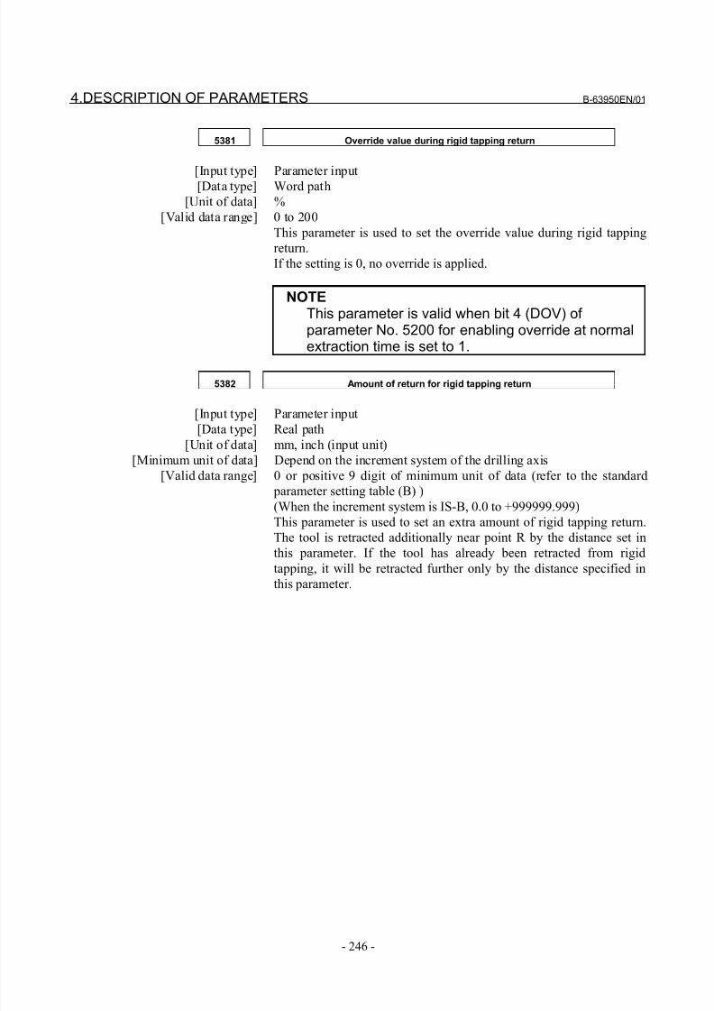
8/21/2019 30i Parameter Manual
http://slidepdf.com/reader/full/30i-parameter-manual 258/493
4.DESCRIPTION OF PARAMETERS B-63950EN/01
- 246 -
5381 Override value during rigid tapping return
[Input type] Parameter input[Data type] Word path
[Unit of data] %
[Valid data range] 0 to 200
This parameter is used to set the override value during rigid tapping
return.
If the setting is 0, no override is applied.
NOTEThis parameter is valid when bit 4 (DOV) of parameter No. 5200 for enabling override at normalextraction time is set to 1.
5382 Amount of return for rigid tapping return
[Input type] Parameter input
[Data type] Real path
[Unit of data] mm, inch (input unit)
[Minimum unit of data] Depend on the increment system of the drilling axis
[Valid data range] 0 or positive 9 digit of minimum unit of data (refer to the standard
parameter setting table (B) )
(When the increment system is IS-B, 0.0 to +999999.999)
This parameter is used to set an extra amount of rigid tapping return.
The tool is retracted additionally near point R by the distance set in
this parameter. If the tool has already been retracted from rigid
tapping, it will be retracted further only by the distance specified in
this parameter.
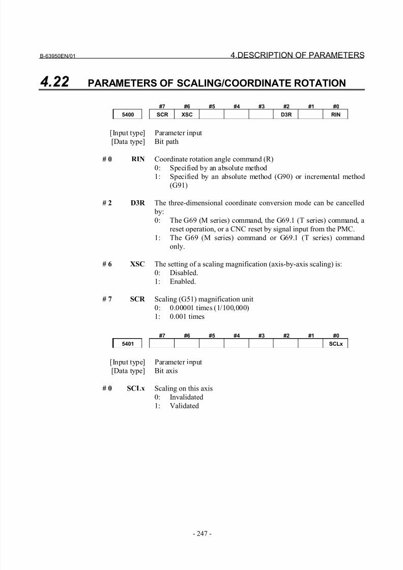
8/21/2019 30i Parameter Manual
http://slidepdf.com/reader/full/30i-parameter-manual 259/493
B-63950EN/01 4.DESCRIPTION OF PARAMETERS
- 247 -
4.22 PARAMETERS OF SCALING/COORDINATE ROTATION
#7 #6 #5 #4 #3 #2 #1 #0
5400 SCR XSC D3R RIN
[Input type] Parameter input
[Data type] Bit path
# 0 RIN Coordinate rotation angle command (R)
0: Specified by an absolute method
1: Specified by an absolute method (G90) or incremental method
(G91)
# 2 D3R The three-dimensional coordinate conversion mode can be cancelled
by:
0: The G69 (M series) command, the G69.1 (T series) command, a
reset operation, or a CNC reset by signal input from the PMC.
1: The G69 (M series) command or G69.1 (T series) command
only.
# 6 XSC The setting of a scaling magnification (axis-by-axis scaling) is:
0: Disabled.
1: Enabled.
# 7 SCR Scaling (G51) magnification unit0: 0.00001 times (1/100,000)
1: 0.001 times
#7 #6 #5 #4 #3 #2 #1 #0
5401 SCLx
[Input type] Parameter input
[Data type] Bit axis
# 0 SCLx Scaling on this axis
0: Invalidated1: Validated
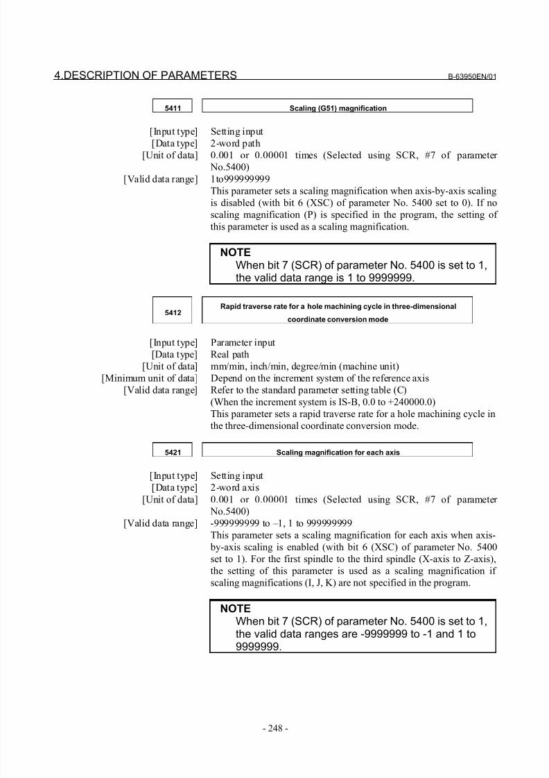
8/21/2019 30i Parameter Manual
http://slidepdf.com/reader/full/30i-parameter-manual 260/493
4.DESCRIPTION OF PARAMETERS B-63950EN/01
- 248 -
5411 Scaling (G51) magnification
[Input type] Setting input[Data type] 2-word path
[Unit of data] 0.001 or 0.00001 times (Selected using SCR, #7 of parameter
No.5400)
[Valid data range] 1to999999999
This parameter sets a scaling magnification when axis-by-axis scaling
is disabled (with bit 6 (XSC) of parameter No. 5400 set to 0). If no
scaling magnification (P) is specified in the program, the setting of
this parameter is used as a scaling magnification.
NOTEWhen bit 7 (SCR) of parameter No. 5400 is set to 1,the valid data range is 1 to 9999999.
5412Rapid traverse rate for a hole machining cycle in three-dimensional
coordinate conversion mode
[Input type] Parameter input
[Data type] Real path
[Unit of data] mm/min, inch/min, degree/min (machine unit)
[Minimum unit of data] Depend on the increment system of the reference axis
[Valid data range] Refer to the standard parameter setting table (C)
(When the increment system is IS-B, 0.0 to +240000.0)
This parameter sets a rapid traverse rate for a hole machining cycle in
the three-dimensional coordinate conversion mode.
5421 Scaling magnification for each axis
[Input type] Setting input
[Data type] 2-word axis
[Unit of data] 0.001 or 0.00001 times (Selected using SCR, #7 of parameter
No.5400)
[Valid data range] -999999999 to –1, 1 to 999999999
This parameter sets a scaling magnification for each axis when axis-
by-axis scaling is enabled (with bit 6 (XSC) of parameter No. 5400set to 1). For the first spindle to the third spindle (X-axis to Z-axis),
the setting of this parameter is used as a scaling magnification if
scaling magnifications (I, J, K) are not specified in the program.
NOTEWhen bit 7 (SCR) of parameter No. 5400 is set to 1,the valid data ranges are -9999999 to -1 and 1 to9999999.
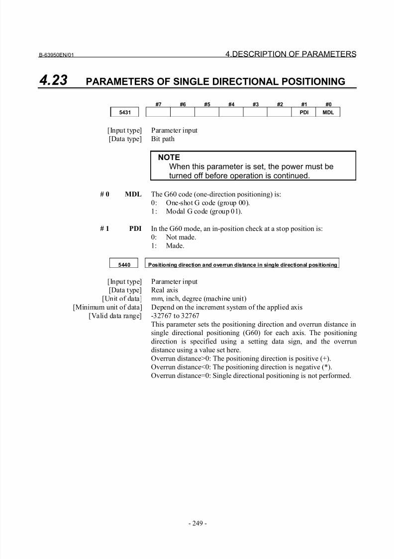
8/21/2019 30i Parameter Manual
http://slidepdf.com/reader/full/30i-parameter-manual 261/493
B-63950EN/01 4.DESCRIPTION OF PARAMETERS
- 249 -
4.23 PARAMETERS OF SINGLE DIRECTIONAL POSITIONING
#7 #6 #5 #4 #3 #2 #1 #0
5431 PDI MDL
[Input type] Parameter input
[Data type] Bit path
NOTEWhen this parameter is set, the power must beturned off before operation is continued.
# 0 MDL The G60 code (one-direction positioning) is:0: One-shot G code (group 00).
1: Modal G code (group 01).
# 1 PDI In the G60 mode, an in-position check at a stop position is:
0: Not made.
1: Made.
5440 Positioning direction and overrun distance in single directional positioning
[Input type] Parameter input
[Data type] Real axis[Unit of data] mm, inch, degree (machine unit)
[Minimum unit of data] Depend on the increment system of the applied axis
[Valid data range] -32767 to 32767
This parameter sets the positioning direction and overrun distance in
single directional positioning (G60) for each axis. The positioning
direction is specified using a setting data sign, and the overrun
distance using a value set here.
Overrun distance>0: The positioning direction is positive (+).
Overrun distance<0: The positioning direction is negative (*).
Overrun distance=0: Single directional positioning is not performed.
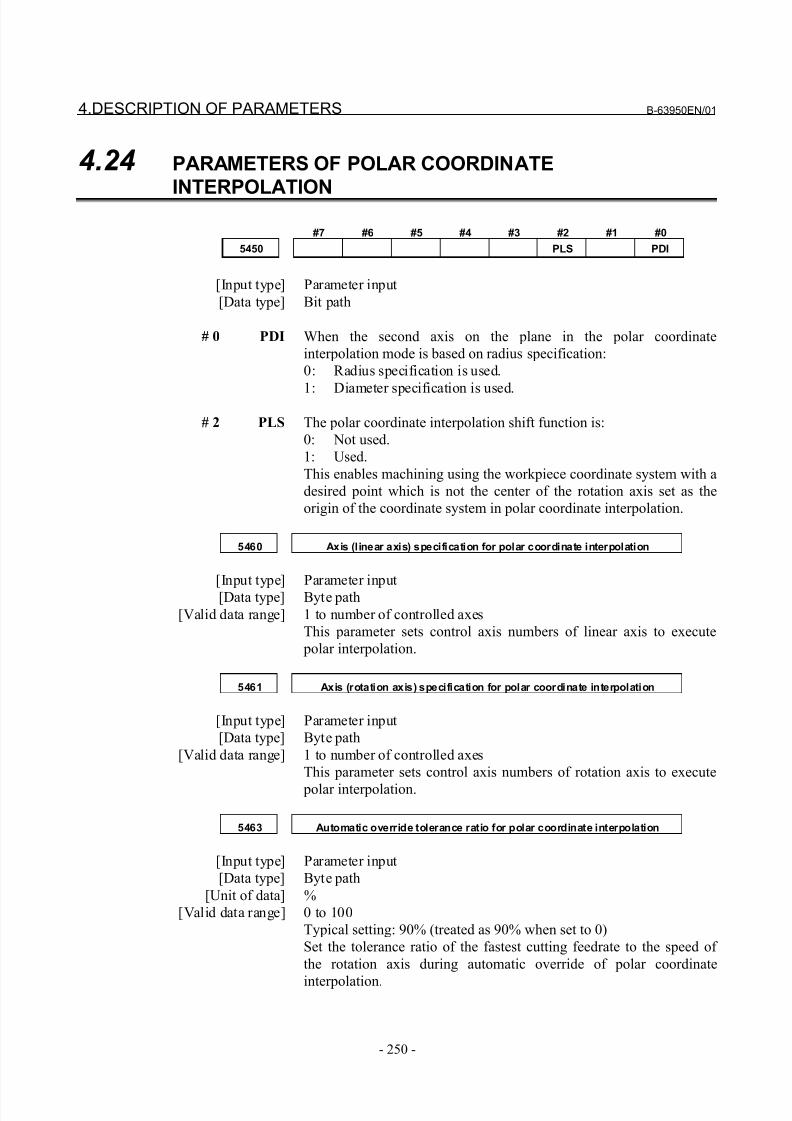
8/21/2019 30i Parameter Manual
http://slidepdf.com/reader/full/30i-parameter-manual 262/493
4.DESCRIPTION OF PARAMETERS B-63950EN/01
- 250 -
4.24 PARAMETERS OF POLAR COORDINATE
INTERPOLATION
#7 #6 #5 #4 #3 #2 #1 #0
5450 PLS PDI
[Input type] Parameter input
[Data type] Bit path
# 0 PDI When the second axis on the plane in the polar coordinate
interpolation mode is based on radius specification:
0: Radius specification is used.
1: Diameter specification is used.
# 2 PLS The polar coordinate interpolation shift function is:
0: Not used.
1: Used.
This enables machining using the workpiece coordinate system with a
desired point which is not the center of the rotation axis set as the
origin of the coordinate system in polar coordinate interpolation.
5460 Axis (linear axis) specification for polar coordinate interpolation
[Input type] Parameter input
[Data type] Byte path
[Valid data range] 1 to number of controlled axes
This parameter sets control axis numbers of linear axis to execute
polar interpolation.
5461 Axis (rotation axis) specification for polar coordinate interpolation
[Input type] Parameter input
[Data type] Byte path
[Valid data range] 1 to number of controlled axes
This parameter sets control axis numbers of rotation axis to execute
polar interpolation.
5463 Automatic override tolerance ratio for polar coordinate interpolation
[Input type] Parameter input
[Data type] Byte path
[Unit of data] %
[Valid data range] 0 to 100
Typical setting: 90% (treated as 90% when set to 0)
Set the tolerance ratio of the fastest cutting feedrate to the speed of
the rotation axis during automatic override of polar coordinate
interpolation.
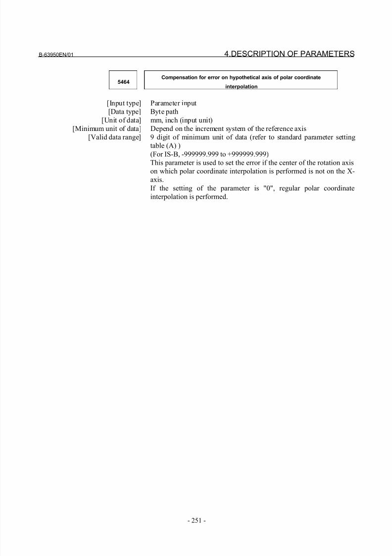
8/21/2019 30i Parameter Manual
http://slidepdf.com/reader/full/30i-parameter-manual 263/493
B-63950EN/01 4.DESCRIPTION OF PARAMETERS
- 251 -
5464Compensation for error on hypothetical axis of polar coordinate
interpolation
[Input type] Parameter input
[Data type] Byte path
[Unit of data] mm, inch (input unit)
[Minimum unit of data] Depend on the increment system of the reference axis
[Valid data range] 9 digit of minimum unit of data (refer to standard parameter setting
table (A) )
(For IS-B, -999999.999 to +999999.999)
This parameter is used to set the error if the center of the rotation axis
on which polar coordinate interpolation is performed is not on the X-
axis.
If the setting of the parameter is "0", regular polar coordinate
interpolation is performed.
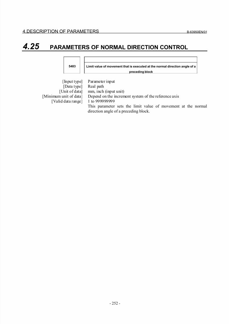
8/21/2019 30i Parameter Manual
http://slidepdf.com/reader/full/30i-parameter-manual 264/493
4.DESCRIPTION OF PARAMETERS B-63950EN/01
- 252 -
4.25 PARAMETERS OF NORMAL DIRECTION CONTROL
5483 Limit value of movement that is executed at the normal direction angle of a
preceding block
[Input type] Parameter input
[Data type] Real path
[Unit of data] mm, inch (input unit)
[Minimum unit of data] Depend on the increment system of the reference axis
[Valid data range] 1 to 999999999
This parameter sets the limit value of movement at the normal
direction angle of a preceding block.
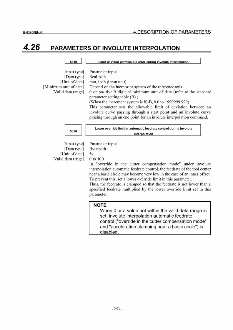
8/21/2019 30i Parameter Manual
http://slidepdf.com/reader/full/30i-parameter-manual 265/493
B-63950EN/01 4.DESCRIPTION OF PARAMETERS
- 253 -
4.26 PARAMETERS OF INVOLUTE INTERPOLATION
5610 Limit of initial permissible error during involute interpolation
[Input type] Parameter input
[Data type] Real path
[Unit of data] mm, inch (input unit)
[Minimum unit of data] Depend on the increment system of the reference axis
[Valid data range] 0 or positive 9 digit of minimum unit of data (refer to the standard
parameter setting table (B) )
(When the increment system is IS-B, 0.0 to +999999.999)
This parameter sets the allowable limit of deviation between an
involute curve passing through a start point and an involute curve
passing through an end point for an involute interpolation command.
5620Lower override limit in automatic feedrate control during involute
interpolation
[Input type] Parameter input
[Data type] Byte path
[Unit of data] %
[Valid data range] 0 to 100
In "override in the cutter compensation mode" under involute
interpolation automatic feedrate control, the feedrate of the tool center
near a basic circle may become very low in the case of an inner offset.To prevent this, set a lower override limit in this parameter.
Thus, the feedrate is clamped so that the feedrate is not lower than a
specified feedrate multiplied by the lower override limit set in this
parameter.
NOTEWhen 0 or a value not within the valid data range isset, involute interpolation automatic feedratecontrol ("override in the cutter compensation mode"and "acceleration clamping near a basic circle") is
disabled.
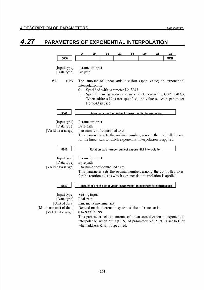
8/21/2019 30i Parameter Manual
http://slidepdf.com/reader/full/30i-parameter-manual 266/493
4.DESCRIPTION OF PARAMETERS B-63950EN/01
- 254 -
4.27 PARAMETERS OF EXPONENTIAL INTERPOLATION
#7 #6 #5 #4 #3 #2 #1 #0
5630 SPN
[Input type] Parameter input
[Data type] Bit path
# 0 SPN The amount of linear axis division (span value) in exponential
interpolation is:
0: Specified with parameter No.5643.
1: Specified using address K in a block containing G02.3/G03.3.
When address K is not specified, the value set with parameter
No.5643 is used.
5641 Linear axis number subject to exponential interpolation
[Input type] Parameter input
[Data type] Byte path
[Valid data range] 1 to number of controlled axes
This parameter sets the ordinal number, among the controlled axes,
for the linear axis to which exponential interpolation is applied.
5642 Rotation axis number subject exponential interpolation
[Input type] Parameter input
[Data type] Byte path
[Valid data range] 1 to number of controlled axes
This parameter sets the ordinal number, among the controlled axes,
for the rotation axis to which exponential interpolation is applied.
5643 Amount of linear axis division (span value) in exponential interpolation
[Input type] Setting input
[Data type] Real path
[Unit of data] mm, inch (machine unit)[Minimum unit of data] Depend on the increment system of the reference axis
[Valid data range] 0 to 999999999
This parameter sets an amount of linear axis division in exponential
interpolation when bit 0 (SPN) of parameter No. 5630 is set to 0 or
when address K is not specified.
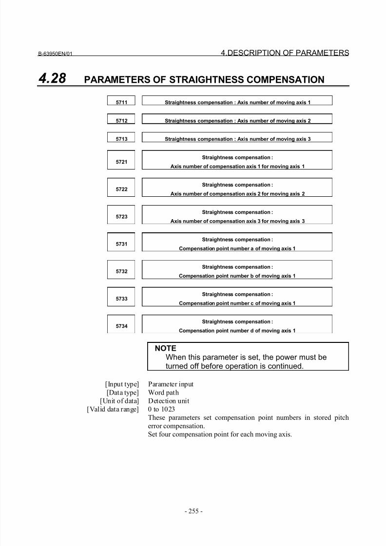
8/21/2019 30i Parameter Manual
http://slidepdf.com/reader/full/30i-parameter-manual 267/493
B-63950EN/01 4.DESCRIPTION OF PARAMETERS
- 255 -
4.28 PARAMETERS OF STRAIGHTNESS COMPENSATION
5711 Straightness compensation : Axis number of moving axis 1
5712 Straightness compensation : Axis number of moving axis 2
5713 Straightness compensation : Axis number of moving axis 3
5721Straightness compensation :
Axis number of compensation axis 1 for moving axis 1
5722
Straightness compensation :
Axis number of compensation axis 2 for moving axis 2
5723Straightness compensation :
Axis number of compensation axis 3 for moving axis 3
5731Straightness compensation :
Compensation point number a of moving axis 1
5732Straightness compensation :
Compensation point number b of moving axis 1
5733Straightness compensation :
Compensation point number c of moving axis 1
5734Straightness compensation :
Compensation point number d of moving axis 1
NOTEWhen this parameter is set, the power must beturned off before operation is continued.
[Input type] Parameter input[Data type] Word path
[Unit of data] Detection unit
[Valid data range] 0 to 1023
These parameters set compensation point numbers in stored pitch
error compensation.
Set four compensation point for each moving axis.
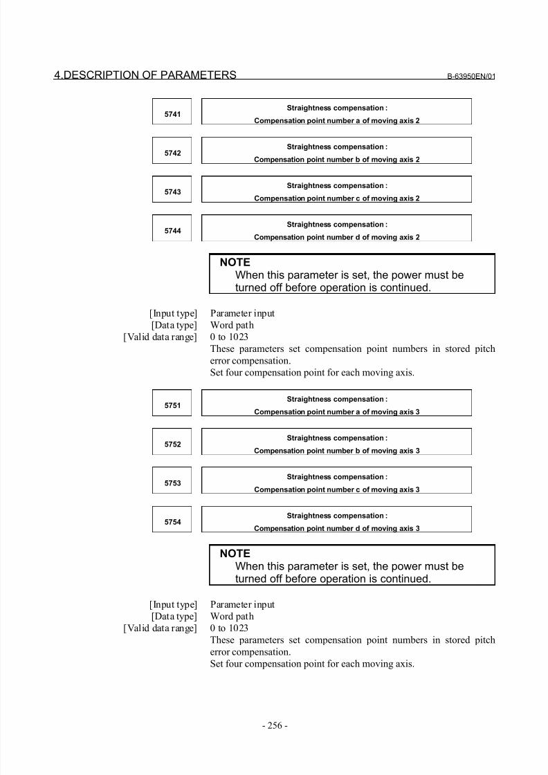
8/21/2019 30i Parameter Manual
http://slidepdf.com/reader/full/30i-parameter-manual 268/493
4.DESCRIPTION OF PARAMETERS B-63950EN/01
- 256 -
5741Straightness compensation :
Compensation point number a of moving axis 2
5742Straightness compensation :
Compensation point number b of moving axis 2
5743Straightness compensation :
Compensation point number c of moving axis 2
5744Straightness compensation :
Compensation point number d of moving axis 2
NOTE
When this parameter is set, the power must beturned off before operation is continued.
[Input type] Parameter input
[Data type] Word path
[Valid data range] 0 to 1023
These parameters set compensation point numbers in stored pitch
error compensation.
Set four compensation point for each moving axis.
5751
Straightness compensation :
Compensation point number a of moving axis 3
5752Straightness compensation :
Compensation point number b of moving axis 3
5753Straightness compensation :
Compensation point number c of moving axis 3
5754Straightness compensation :
Compensation point number d of moving axis 3
NOTEWhen this parameter is set, the power must beturned off before operation is continued.
[Input type] Parameter input
[Data type] Word path
[Valid data range] 0 to 1023
These parameters set compensation point numbers in stored pitch
error compensation.
Set four compensation point for each moving axis.
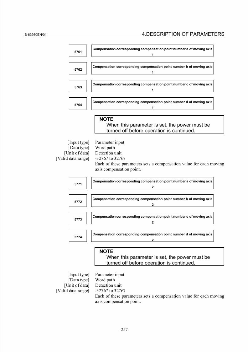
8/21/2019 30i Parameter Manual
http://slidepdf.com/reader/full/30i-parameter-manual 269/493
B-63950EN/01 4.DESCRIPTION OF PARAMETERS
- 257 -
5761Compensation corresponding compensation point number a of moving axis
1
5762Compensation corresponding compensation point number b of moving axis
1
5763Compensation corresponding compensation point number c of moving axis
1
5764Compensation corresponding compensation point number d of moving axis
1
NOTE
When this parameter is set, the power must beturned off before operation is continued.
[Input type] Parameter input
[Data type] Word path
[Unit of data] Detection unit
[Valid data range] -32767 to 32767
Each of these parameters sets a compensation value for each moving
axis compensation point.
5771
Compensation corresponding compensation point number a of moving axis
2
5772Compensation corresponding compensation point number b of moving axis
2
5773Compensation corresponding compensation point number c of moving axis
2
5774Compensation corresponding compensation point number d of moving axis
2
NOTEWhen this parameter is set, the power must beturned off before operation is continued.
[Input type] Parameter input
[Data type] Word path
[Unit of data] Detection unit
[Valid data range] -32767 to 32767
Each of these parameters sets a compensation value for each moving
axis compensation point.
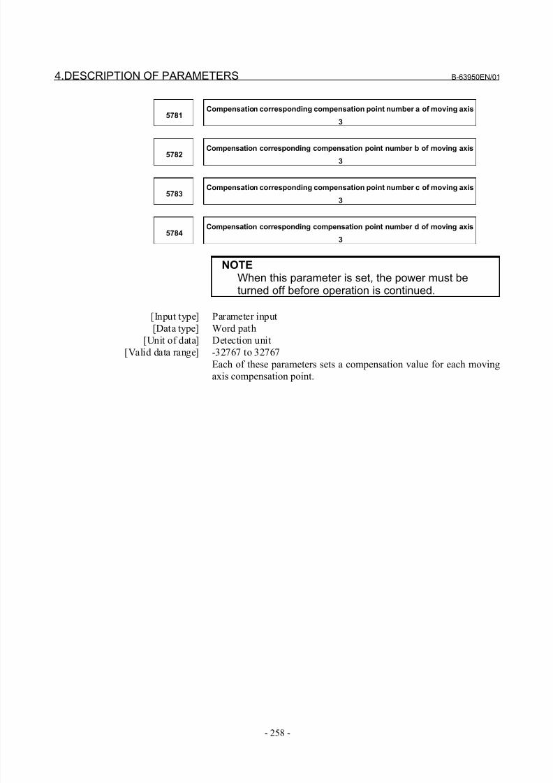
8/21/2019 30i Parameter Manual
http://slidepdf.com/reader/full/30i-parameter-manual 270/493
4.DESCRIPTION OF PARAMETERS B-63950EN/01
- 258 -
5781Compensation corresponding compensation point number a of moving axis
3
5782Compensation corresponding compensation point number b of moving axis
3
5783Compensation corresponding compensation point number c of moving axis
3
5784Compensation corresponding compensation point number d of moving axis
3
NOTE
When this parameter is set, the power must beturned off before operation is continued.
[Input type] Parameter input
[Data type] Word path
[Unit of data] Detection unit
[Valid data range] -32767 to 32767
Each of these parameters sets a compensation value for each moving
axis compensation point.
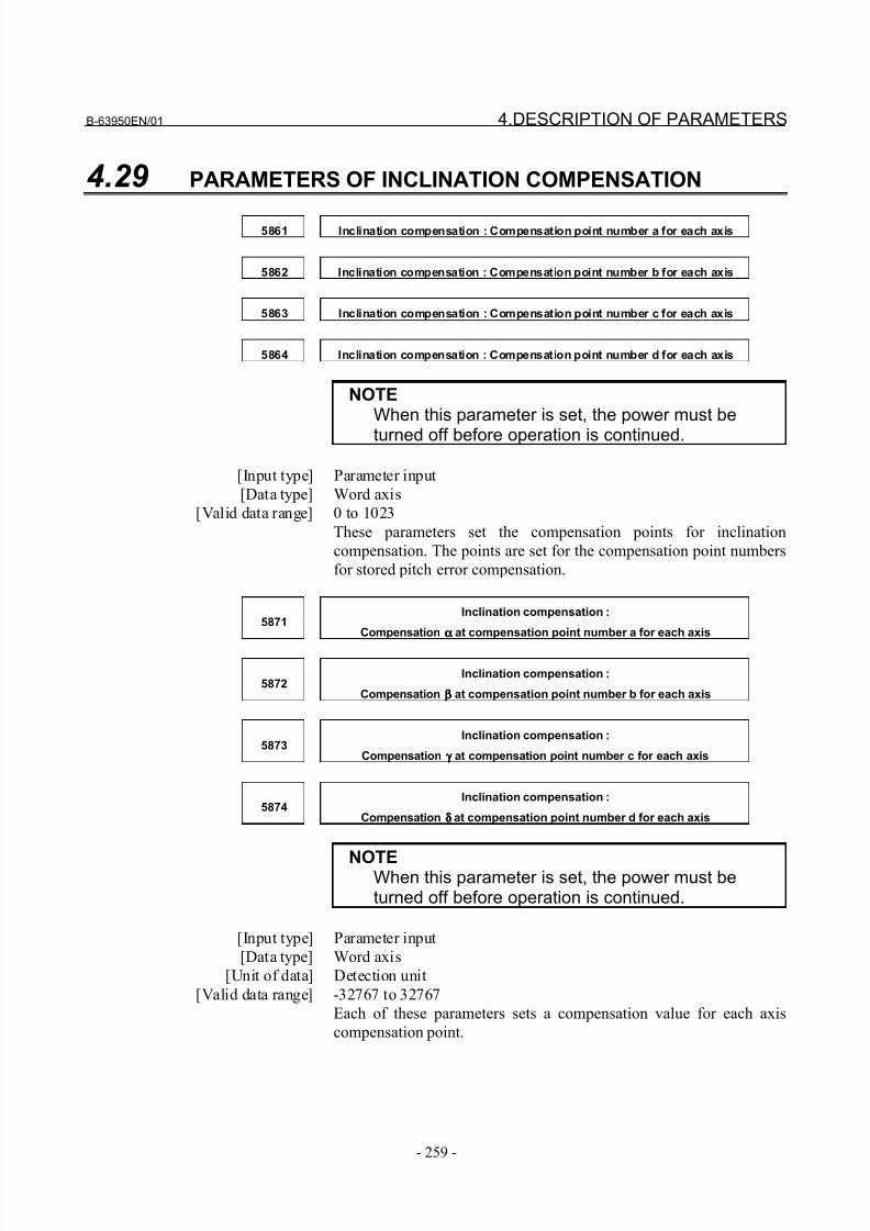
8/21/2019 30i Parameter Manual
http://slidepdf.com/reader/full/30i-parameter-manual 271/493
B-63950EN/01 4.DESCRIPTION OF PARAMETERS
- 259 -
4.29 PARAMETERS OF INCLINATION COMPENSATION
5861 Inclination compensation : Compensation point number a for each axis
5862 Inclination compensation : Compensation point number b for each axis
5863 Inclination compensation : Compensation point number c for each axis
5864 Inclination compensation : Compensation point number d for each axis
NOTEWhen this parameter is set, the power must be
turned off before operation is continued.
[Input type] Parameter input
[Data type] Word axis
[Valid data range] 0 to 1023
These parameters set the compensation points for inclination
compensation. The points are set for the compensation point numbers
for stored pitch error compensation.
5871Inclination compensation :
Compensation αααα at compensation point number a for each axis
5872Inclination compensation :
Compensation ββββ at compensation point number b for each axis
5873Inclination compensation :
Compensation γ γγ γ at compensation point number c for each axis
5874Inclination compensation :
Compensation δδδδ at compensation point number d for each axis
NOTEWhen this parameter is set, the power must beturned off before operation is continued.
[Input type] Parameter input
[Data type] Word axis
[Unit of data] Detection unit
[Valid data range] -32767 to 32767
Each of these parameters sets a compensation value for each axis
compensation point.
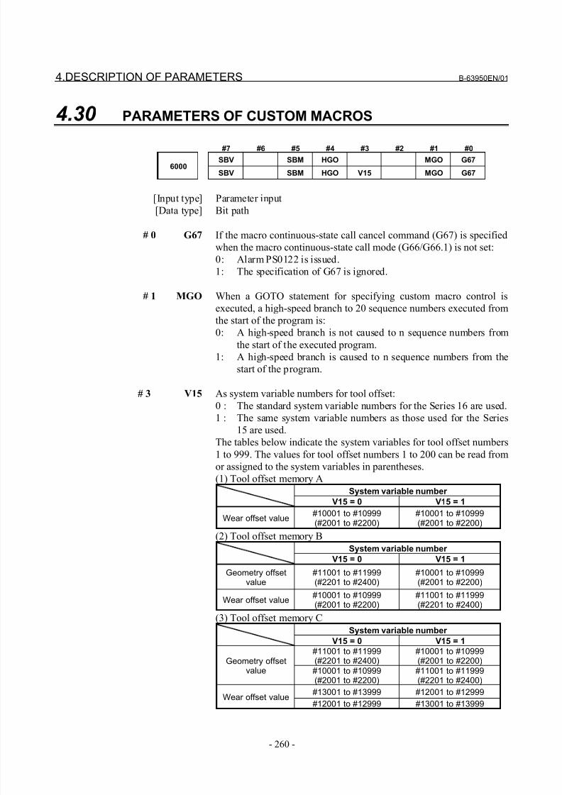
8/21/2019 30i Parameter Manual
http://slidepdf.com/reader/full/30i-parameter-manual 272/493
4.DESCRIPTION OF PARAMETERS B-63950EN/01
- 260 -
4.30 PARAMETERS OF CUSTOM MACROS
#7 #6 #5 #4 #3 #2 #1 #0
SBV SBM HGO MGO G676000
SBV SBM HGO V15 MGO G67
[Input type] Parameter input
[Data type] Bit path
# 0 G67 If the macro continuous-state call cancel command (G67) is specified
when the macro continuous-state call mode (G66/G66.1) is not set:
0: Alarm PS0122 is issued.
1: The specification of G67 is ignored.
# 1 MGO When a GOTO statement for specifying custom macro control is
executed, a high-speed branch to 20 sequence numbers executed from
the start of the program is:
0: A high-speed branch is not caused to n sequence numbers from
the start of the executed program.
1: A high-speed branch is caused to n sequence numbers from the
start of the program.
# 3 V15 As system variable numbers for tool offset:
0 : The standard system variable numbers for the Series 16 are used.
1 : The same system variable numbers as those used for the Series15 are used.
The tables below indicate the system variables for tool offset numbers
1 to 999. The values for tool offset numbers 1 to 200 can be read from
or assigned to the system variables in parentheses.
(1) Tool offset memory A
System variable number
V15 = 0 V15 = 1
Wear offset value#10001 to #10999(#2001 to #2200)
#10001 to #10999(#2001 to #2200)
(2) Tool offset memory B
System variable number
V15 = 0 V15 = 1
Geometry offsetvalue
#11001 to #11999(#2201 to #2400)
#10001 to #10999(#2001 to #2200)
Wear offset value#10001 to #10999(#2001 to #2200)
#11001 to #11999(#2201 to #2400)
(3) Tool offset memory C
System variable number
V15 = 0 V15 = 1
#11001 to #11999(#2201 to #2400)
#10001 to #10999(#2001 to #2200)Geometry offset
value #10001 to #10999(#2001 to #2200)
#11001 to #11999(#2201 to #2400)
#13001 to #13999 #12001 to #12999Wear offset value #12001 to #12999 #13001 to #13999
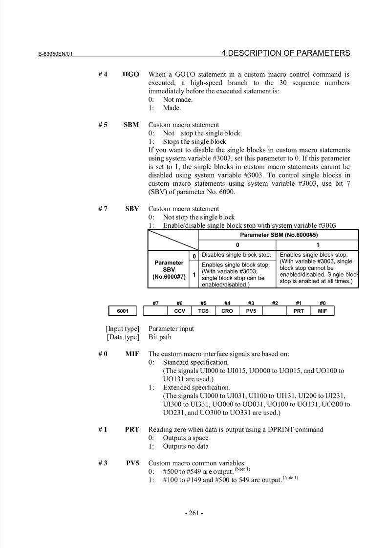
8/21/2019 30i Parameter Manual
http://slidepdf.com/reader/full/30i-parameter-manual 273/493
B-63950EN/01 4.DESCRIPTION OF PARAMETERS
- 261 -
# 4 HGO When a GOTO statement in a custom macro control command is
executed, a high-speed branch to the 30 sequence numbers
immediately before the executed statement is:
0: Not made.
1: Made.
# 5 SBM Custom macro statement
0: Not stop the single block
1: Stops the single block
If you want to disable the single blocks in custom macro statements
using system variable #3003, set this parameter to 0. If this parameter
is set to 1, the single blocks in custom macro statements cannot be
disabled using system variable #3003. To control single blocks in
custom macro statements using system variable #3003, use bit 7
(SBV) of parameter No. 6000.
# 7 SBV Custom macro statement
0: Not stop the single block
1: Enable/disable single block stop with system variable #3003
Parameter SBM (No.6000#5)
0 1
0 Disables single block stop.
Parameter
SBV
(No.6000#7) 1
Enables single block stop.(With variable #3003,single block stop can beenabled/disabled.)
Enables single block stop.(With variable #3003, singleblock stop cannot beenabled/disabled. Single blockstop is enabled at all times.)
#7 #6 #5 #4 #3 #2 #1 #0
6001 CCV TCS CRO PV5 PRT MIF
[Input type] Parameter input
[Data type] Bit path
# 0 MIF The custom macro interface signals are based on:
0: Standard specification.
(The signals UI000 to UI015, UO000 to UO015, and UO100 to
UO131 are used.)
1: Extended specification.
(The signals UI000 to UI031, UI100 to UI131, UI200 to UI231,
UI300 to UI331, UO000 to UO031, UO100 to UO131, UO200 to
UO231, and UO300 to UO331 are used.)
# 1 PRT Reading zero when data is output using a DPRINT command
0: Outputs a space
1: Outputs no data
# 3 PV5 Custom macro common variables:
0: #500 to #549 are output.(Note 1)
1: #100 to #149 and #500 to 549 are output.(Note 1)
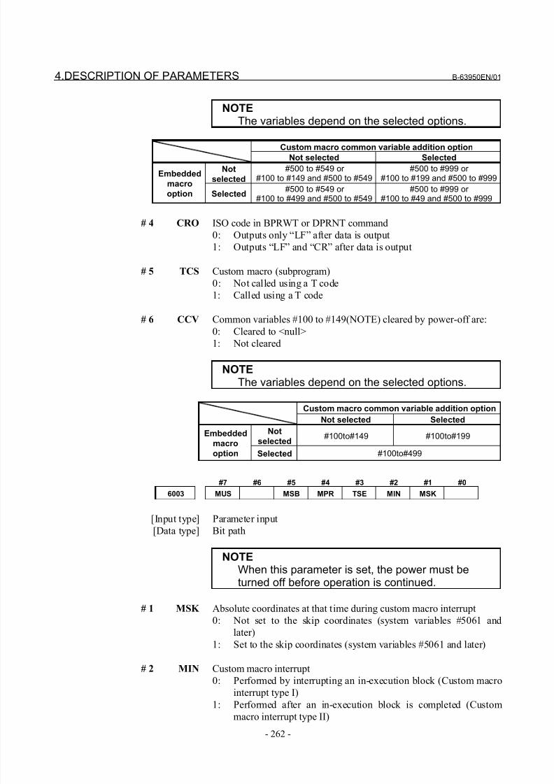
8/21/2019 30i Parameter Manual
http://slidepdf.com/reader/full/30i-parameter-manual 274/493
4.DESCRIPTION OF PARAMETERS B-63950EN/01
- 262 -
NOTEThe variables depend on the selected options.
Custom macro common variable addition option
Not selected Selected
Not
selected
#500 to #549 or #100 to #149 and #500 to #549
#500 to #999 or #100 to #199 and #500 to #999
Embedded
macro
option Selected#500 to #549 or
#100 to #499 and #500 to #549#500 to #999 or
#100 to #49 and #500 to #999
# 4 CRO ISO code in BPRWT or DPRNT command
0: Outputs only “LF” after data is output
1: Outputs “LF” and “CR” after data is output
# 5 TCS Custom macro (subprogram)0: Not called using a T code
1: Called using a T code
# 6 CCV Common variables #100 to #149(NOTE) cleared by power-off are:
0: Cleared to <null>
1: Not cleared
NOTEThe variables depend on the selected options.
Custom macro common variable addition optionNot selected Selected
Not
selected#100to#149 #100to#199Embedded
macro
option Selected #100to#499
#7 #6 #5 #4 #3 #2 #1 #0
6003 MUS MSB MPR TSE MIN MSK
[Input type] Parameter input
[Data type] Bit path
NOTEWhen this parameter is set, the power must beturned off before operation is continued.
# 1 MSK Absolute coordinates at that time during custom macro interrupt
0: Not set to the skip coordinates (system variables #5061 and
later)
1: Set to the skip coordinates (system variables #5061 and later)
# 2 MIN Custom macro interrupt
0: Performed by interrupting an in-execution block (Custom macro
interrupt type I)
1: Performed after an in-execution block is completed (Custom
macro interrupt type II)
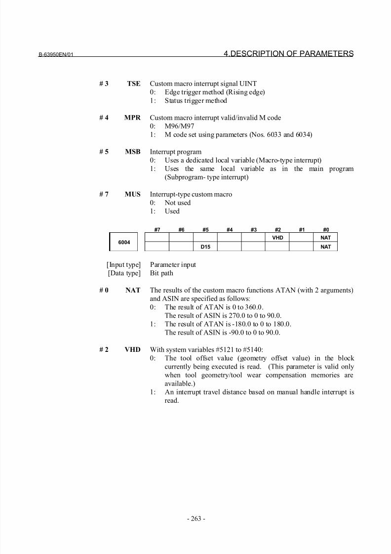
8/21/2019 30i Parameter Manual
http://slidepdf.com/reader/full/30i-parameter-manual 275/493
B-63950EN/01 4.DESCRIPTION OF PARAMETERS
- 263 -
# 3 TSE Custom macro interrupt signal UINT
0: Edge trigger method (Rising edge)
1: Status trigger method
# 4 MPR Custom macro interrupt valid/invalid M code
0: M96/M97
1: M code set using parameters (Nos. 6033 and 6034)
# 5 MSB Interrupt program
0: Uses a dedicated local variable (Macro-type interrupt)
1: Uses the same local variable as in the main program
(Subprogram- type interrupt)
# 7 MUS Interrupt-type custom macro0: Not used
1: Used
#7 #6 #5 #4 #3 #2 #1 #0
VHD NAT6004
D15 NAT
[Input type] Parameter input
[Data type] Bit path
# 0 NAT The results of the custom macro functions ATAN (with 2 arguments)and ASIN are specified as follows:
0: The result of ATAN is 0 to 360.0.
The result of ASIN is 270.0 to 0 to 90.0.
1: The result of ATAN is -180.0 to 0 to 180.0.
The result of ASIN is -90.0 to 0 to 90.0.
# 2 VHD With system variables #5121 to #5140:
0: The tool offset value (geometry offset value) in the block
currently being executed is read. (This parameter is valid only
when tool geometry/tool wear compensation memories are
available.)
1: An interrupt travel distance based on manual handle interrupt is
read.
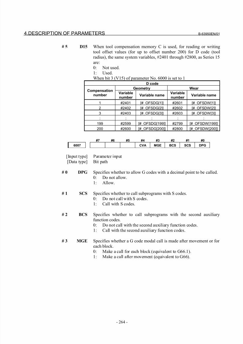
8/21/2019 30i Parameter Manual
http://slidepdf.com/reader/full/30i-parameter-manual 276/493
4.DESCRIPTION OF PARAMETERS B-63950EN/01
- 264 -
# 5 D15 When tool compensation memory C is used, for reading or writing
tool offset values (for up to offset number 200) for D code (tool
radius), the same system variables, #2401 through #2800, as Series 15
are:
0: Not used.
1: Used.
When bit 3 (V15) of parameter No. 6000 is set to 1
D code
Geometry Wear Compensation
number Variable
number Variable name
Variable
number Variable name
1 #2401 [#_OFSDG[1]] #2601 [#_OFSDW[1]]
2 #2402 [#_OFSDG[2]] #2602 [#_OFSDW[2]]
3 #2403 [#_OFSDG[3]] #2603 [#_OFSDW[3]]
: : : : :
199 #2599 [#_OFSDG[199]] #2799 [#_OFSDW[199]]
200 #2600 [#_OFSDG[200]] #2800 [#_OFSDW[200]]
#7 #6 #5 #4 #3 #2 #1 #0
6007 CVA MGE BCS SCS DPG
[Input type] Parameter input
[Data type] Bit path
# 0 DPG Specifies whether to allow G codes with a decimal point to be called.
0: Do not allow.
1: Allow.
# 1 SCS Specifies whether to call subprograms with S codes.
0: Do not call with S codes.
1: Call with S codes.
# 2 BCS Specifies whether to call subprograms with the second auxiliary
function codes.
0: Do not call with the second auxiliary function codes.
1: Call with the second auxiliary function codes.
# 3 MGE Specifies whether a G code modal call is made after movement or for each block.
0: Make a call for each block (equivalent to G66.1).
1: Make a call after movement (equivalent to G66).
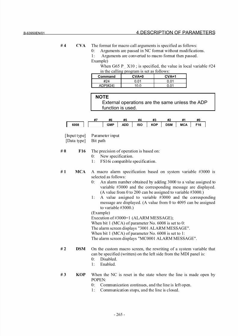
8/21/2019 30i Parameter Manual
http://slidepdf.com/reader/full/30i-parameter-manual 277/493
B-63950EN/01 4.DESCRIPTION OF PARAMETERS
- 265 -
# 4 CVA The format for macro call arguments is specified as follows:
0: Arguments are passed in NC format without modifications.
1: Arguments are converted to macro format then passed.
Example)
When G65 P_ X10 ; is specified, the value in local variable #24
in the calling program is set as follows:
Command CVA=0 CVA=1
#24 0.01 0.01 ADP[#24] 10.0 0.01
NOTEExternal operations are the same unless the ADPfunction is used.
#7 #6 #5 #4 #3 #2 #1 #0
6008 GMP ADD ISO KOP DSM MCA F16
[Input type] Parameter input
[Data type] Bit path
# 0 F16 The precision of operation is based on:
0: New specification.
1: FS16i compatible specification.
# 1 MCA A macro alarm specification based on system variable #3000 is
selected as follows:0: An alarm number obtained by adding 3000 to a value assigned to
variable #3000 and the corresponding message are displayed.
(A value from 0 to 200 can be assigned to variable #3000.)
1: A value assigned to variable #3000 and the corresponding
message are displayed. (A value from 0 to 4095 can be assigned
to variable #3000.)
(Example)
Execution of #3000=1 (ALARM MESSAGE);
When bit 1 (MCA) of parameter No. 6008 is set to 0:
The alarm screen displays "3001 ALARM MESSAGE".
When bit 1 (MCA) of parameter No. 6008 is set to 1:The alarm screen displays "MC0001 ALARM MESSAGE".
# 2 DSM On the custom macro screen, the rewriting of a system variable that
can be specified (written) on the left side from the MDI panel is:
0: Disabled.
1: Enabled.
# 3 KOP When the NC is reset in the state where the line is made open by
POPEN:
0: Communication continues, and the line is left open.
1: Communication stops, and the line is closed.
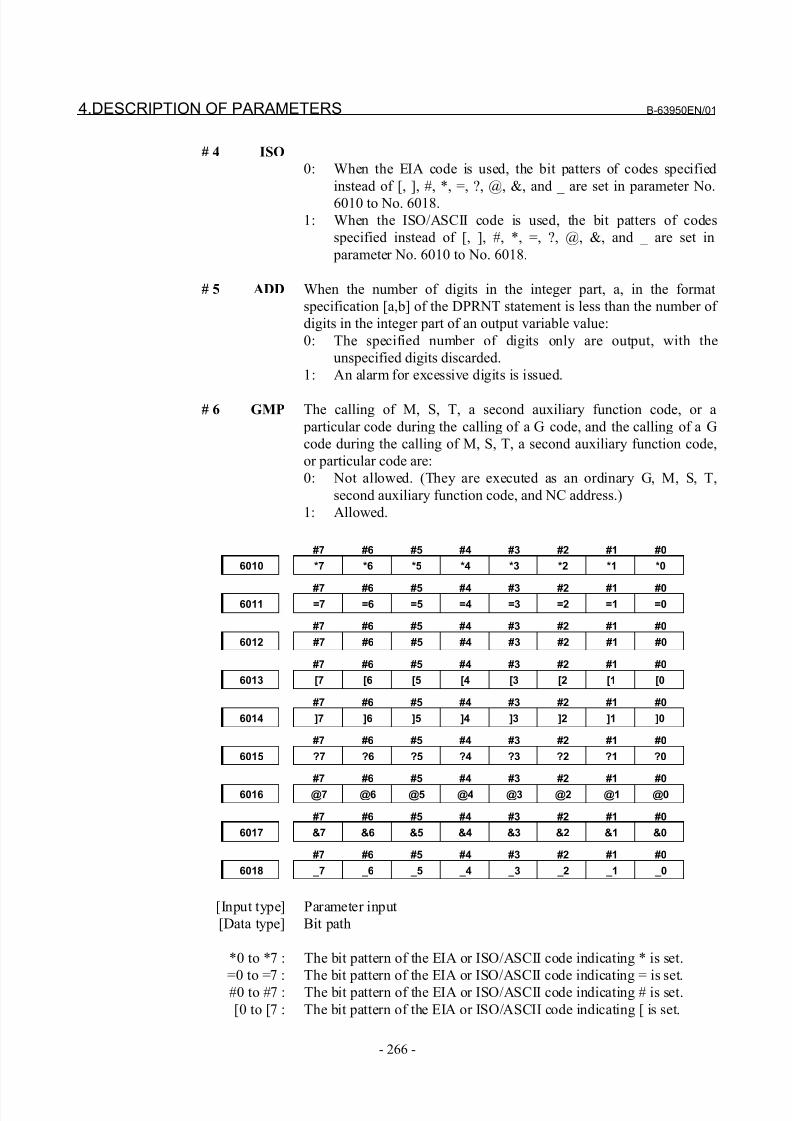
8/21/2019 30i Parameter Manual
http://slidepdf.com/reader/full/30i-parameter-manual 278/493
4.DESCRIPTION OF PARAMETERS B-63950EN/01
- 266 -
# 4 ISO
0: When the EIA code is used, the bit patters of codes specified
instead of [, ], #, *, =, ?, @, &, and _ are set in parameter No.
6010 to No. 6018.
1: When the ISO/ASCII code is used, the bit patters of codes
specified instead of [, ], #, *, =, ?, @, &, and _ are set in
parameter No. 6010 to No. 6018.
# 5 ADD When the number of digits in the integer part, a, in the format
specification [a,b] of the DPRNT statement is less than the number of
digits in the integer part of an output variable value:
0: The specified number of digits only are output, with the
unspecified digits discarded.
1: An alarm for excessive digits is issued.
# 6 GMP The calling of M, S, T, a second auxiliary function code, or a
particular code during the calling of a G code, and the calling of a G
code during the calling of M, S, T, a second auxiliary function code,
or particular code are:
0: Not allowed. (They are executed as an ordinary G, M, S, T,
second auxiliary function code, and NC address.)
1: Allowed.
#7 #6 #5 #4 #3 #2 #1 #0
6010 *7 *6 *5 *4 *3 *2 *1 *0
#7 #6 #5 #4 #3 #2 #1 #06011 =7 =6 =5 =4 =3 =2 =1 =0
#7 #6 #5 #4 #3 #2 #1 #0
6012 #7 #6 #5 #4 #3 #2 #1 #0
#7 #6 #5 #4 #3 #2 #1 #0
6013 [7 [6 [5 [4 [3 [2 [1 [0
#7 #6 #5 #4 #3 #2 #1 #0
6014 ]7 ]6 ]5 ]4 ]3 ]2 ]1 ]0
#7 #6 #5 #4 #3 #2 #1 #0
6015 ?7 ?6 ?5 ?4 ?3 ?2 ?1 ?0
#7 #6 #5 #4 #3 #2 #1 #0
6016 @7 @6 @5 @4 @3 @2 @1 @0
#7 #6 #5 #4 #3 #2 #1 #0
6017 &7 &6 &5 &4 &3 &2 &1 &0
#7 #6 #5 #4 #3 #2 #1 #0
6018 _7 _6 _5 _4 _3 _2 _1 _0
[Input type] Parameter input
[Data type] Bit path
*0 to *7 : The bit pattern of the EIA or ISO/ASCII code indicating * is set.
=0 to =7 : The bit pattern of the EIA or ISO/ASCII code indicating = is set.#0 to #7 : The bit pattern of the EIA or ISO/ASCII code indicating # is set.
[0 to [7 : The bit pattern of the EIA or ISO/ASCII code indicating [ is set.
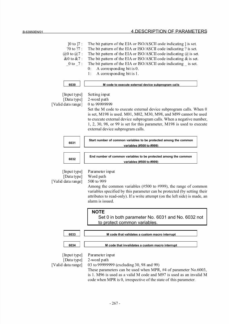
8/21/2019 30i Parameter Manual
http://slidepdf.com/reader/full/30i-parameter-manual 279/493
B-63950EN/01 4.DESCRIPTION OF PARAMETERS
- 267 -
]0 to ]7 : The bit pattern of the EIA or ISO/ASCII code indicating ] is set.
?0 to ?7 : The bit pattern of the EIA or ISO/ASCII code indicating ? is set.
@0 to @7 : The bit pattern of the EIA or ISO/ASCII code indicating @ is set.
&0 to &7 : The bit pattern of the EIA or ISO/ASCII code indicating & is set.
_0 to _7 : The bit pattern of the EIA or ISO/ASCII code indicating _ is set.
0: A corresponding bit is 0.
1: A corresponding bit is 1.
6030 M code to execute external device subprogram calls
[Input type] Setting input
[Data type] 2-word path
[Valid data range] 0 to 99999999
Set the M code to execute external device subprogram calls. When 0
is set, M198 is used. M01, M02, M30, M98, and M99 cannot be usedto execute external device subprogram calls. When a negative number,
1, 2, 30, 98, or 99 is set for this parameter, M198 is used to execute
external device subprogram calls.
6031Start number of common variables to be protected among the common
variables (#500 to #999)
6032End number of common variables to be protected among the common
variables (#500 to #999)
[Input type] Parameter input[Data type] Word path
[Valid data range] 500 to 999
Among the common variables (#500 to #999), the range of common
variables specified by this parameter can be protected (by setting their
attributes to read-only). If a write attempt (on the left side) is made, an
alarm is issued.
NOTESet 0 in both parameter No. 6031 and No. 6032 notto protect common variables.
6033 M code that validates a custom macro interrupt
6034 M code that invalidates a custom macro interrupt
[Input type] Parameter input
[Data type] 2-word path
[Valid data range] 03 to 99999999 (excluding 30, 98 and 99)
These parameters can be used when MPR, #4 of parameter No.6003,
is 1. M96 is used as a valid M code and M97 is used as an invalid M
code when MPR is 0, irrespective of the state of this parameter.
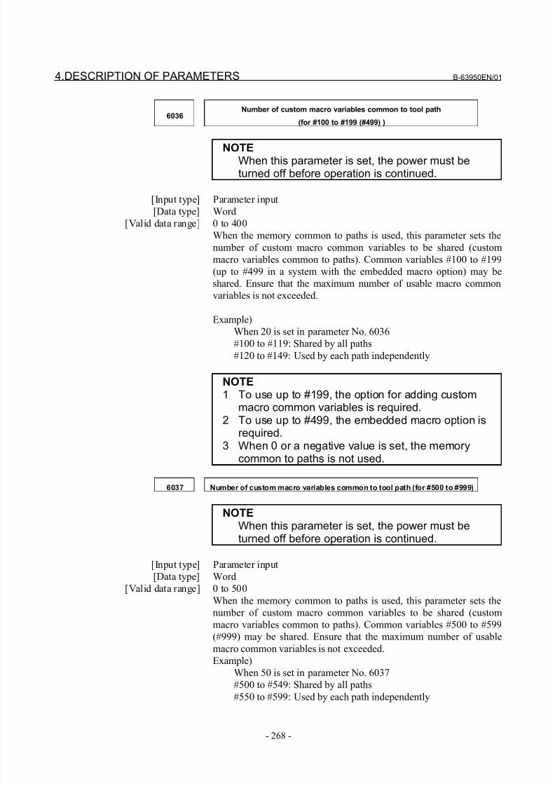
8/21/2019 30i Parameter Manual
http://slidepdf.com/reader/full/30i-parameter-manual 280/493
4.DESCRIPTION OF PARAMETERS B-63950EN/01
- 268 -
6036Number of custom macro variables common to tool path
(for #100 to #199 (#499) )
NOTEWhen this parameter is set, the power must beturned off before operation is continued.
[Input type] Parameter input
[Data type] Word
[Valid data range] 0 to 400
When the memory common to paths is used, this parameter sets the
number of custom macro common variables to be shared (custom
macro variables common to paths). Common variables #100 to #199
(up to #499 in a system with the embedded macro option) may beshared. Ensure that the maximum number of usable macro common
variables is not exceeded.
Example)
When 20 is set in parameter No. 6036
#100 to #119: Shared by all paths
#120 to #149: Used by each path independently
NOTE1 To use up to #199, the option for adding custom
macro common variables is required.2 To use up to #499, the embedded macro option isrequired.
3 When 0 or a negative value is set, the memorycommon to paths is not used.
6037 Number of custom macro variables common to tool path (for #500 to #999)
NOTEWhen this parameter is set, the power must beturned off before operation is continued.
[Input type] Parameter input
[Data type] Word
[Valid data range] 0 to 500
When the memory common to paths is used, this parameter sets the
number of custom macro common variables to be shared (custom
macro variables common to paths). Common variables #500 to #599
(#999) may be shared. Ensure that the maximum number of usable
macro common variables is not exceeded.
Example)
When 50 is set in parameter No. 6037
#500 to #549: Shared by all paths#550 to #599: Used by each path independently
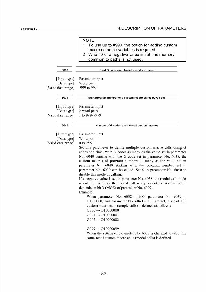
8/21/2019 30i Parameter Manual
http://slidepdf.com/reader/full/30i-parameter-manual 281/493
B-63950EN/01 4.DESCRIPTION OF PARAMETERS
- 269 -
NOTE1 To use up to #999, the option for adding custom
macro common variables is required.2 When 0 or a negative value is set, the memorycommon to paths is not used.
6038 Start G code used to call a custom macro
[Input type] Parameter input
[Data type] Word path
[Valid data range] -999 to 999
6039 Start program number of a custom macro called by G code
[Input type] Parameter input
[Data type] 2-word path
[Valid data range] 1 to 99999999
6040 Number of G codes used to call custom macros
[Input type] Parameter input
[Data type] Word path
[Valid data range] 0 to 255
Set this parameter to define multiple custom macro calls using G
codes at a time. With G codes as many as the value set in parameter No. 6040 starting with the G code set in parameter No. 6038, the
custom macros of program numbers as many as the value set in
parameter No. 6040 starting with the program number set in
parameter No. 6039 can be called. Set 0 in parameter No. 6040 to
disable this mode of calling.
If a negative value is set in parameter No. 6038, the modal call mode
is entered. Whether the modal call is equivalent to G66 or G66.1
depends on bit 3 (MGE) of parameter No. 6007.
Example)
When parameter No. 6038 = 900, parameter No. 6039 =
10000000, and parameter No. 6040 = 100 are set, a set of 100
custom macro calls (simple calls) is defined as follows:G900 → O10000000
G901 → O10000001
G902 → O10000002
:
G999 → O10000099
When the setting of parameter No. 6038 is changed to -900, the
same set of custom macro calls (modal calls) is defined.
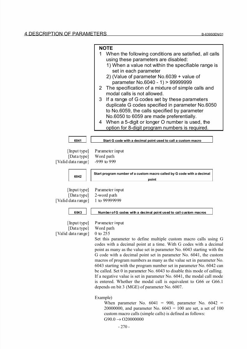
8/21/2019 30i Parameter Manual
http://slidepdf.com/reader/full/30i-parameter-manual 282/493
4.DESCRIPTION OF PARAMETERS B-63950EN/01
- 270 -
NOTE1 When the following conditions are satisfied, all calls
using these parameters are disabled:1) When a value not within the specifiable range isset in each parameter
2) (Value of parameter No.6039 + value of parameter No.6040 - 1) > 99999999
2 The specification of a mixture of simple calls andmodal calls is not allowed.
3 If a range of G codes set by these parametersduplicate G codes specified in parameter No.6050to No.6059, the calls specified by parameter No.6050 to 6059 are made preferentially.
4 When a 5-digit or longer O number is used, theoption for 8-digit program numbers is required.
6041 Start G code with a decimal point used to call a custom macro
[Input type] Parameter input
[Data type] Word path
[Valid data range] -999 to 999
6042Start program number of a custom macro called by G code with a decimal
point
[Input type] Parameter input
[Data type] 2-word path
[Valid data range] 1 to 99999999
6043 Number of G codes with a decimal point used to call custom macros
[Input type] Parameter input
[Data type] Word path
[Valid data range] 0 to 255
Set this parameter to define multiple custom macro calls using G
codes with a decimal point at a time. With G codes with a decimal point as many as the value set in parameter No. 6043 starting with the
G code with a decimal point set in parameter No. 6041, the custom
macros of program numbers as many as the value set in parameter No.
6043 starting with the program number set in parameter No. 6042 can
be called. Set 0 in parameter No. 6043 to disable this mode of calling.
If a negative value is set in parameter No. 6041, the modal call mode
is entered. Whether the modal call is equivalent to G66 or G66.1
depends on bit 3 (MGE) of parameter No. 6007.
Example)
When parameter No. 6041 = 900, parameter No. 6042 =
20000000, and parameter No. 6043 = 100 are set, a set of 100
custom macro calls (simple calls) is defined as follows:
G90.0 → O20000000
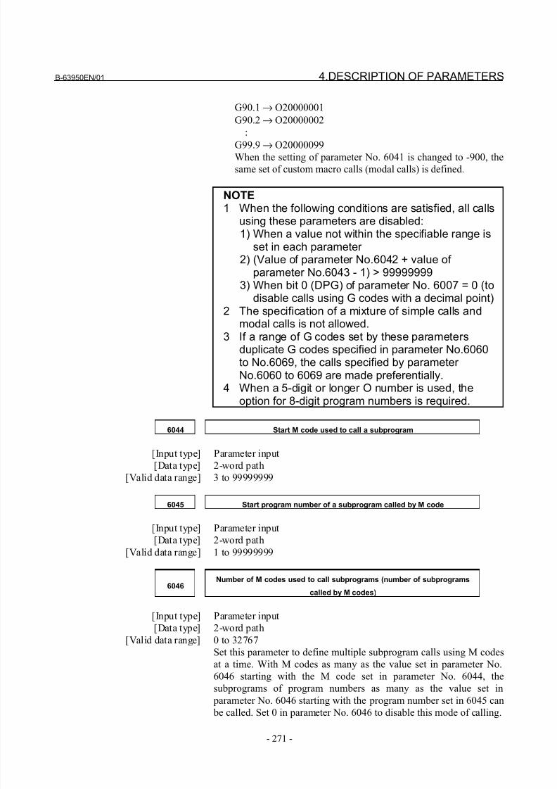
8/21/2019 30i Parameter Manual
http://slidepdf.com/reader/full/30i-parameter-manual 283/493
B-63950EN/01 4.DESCRIPTION OF PARAMETERS
- 271 -
G90.1 → O20000001
G90.2 → O20000002
:
G99.9 → O20000099
When the setting of parameter No. 6041 is changed to -900, the
same set of custom macro calls (modal calls) is defined.
NOTE1 When the following conditions are satisfied, all calls
using these parameters are disabled:1) When a value not within the specifiable range is
set in each parameter 2) (Value of parameter No.6042 + value of
parameter No.6043 - 1) > 999999993) When bit 0 (DPG) of parameter No. 6007 = 0 (todisable calls using G codes with a decimal point)
2 The specification of a mixture of simple calls andmodal calls is not allowed.
3 If a range of G codes set by these parametersduplicate G codes specified in parameter No.6060to No.6069, the calls specified by parameter No.6060 to 6069 are made preferentially.
4 When a 5-digit or longer O number is used, theoption for 8-digit program numbers is required.
6044 Start M code used to call a subprogram
[Input type] Parameter input
[Data type] 2-word path
[Valid data range] 3 to 99999999
6045 Start program number of a subprogram called by M code
[Input type] Parameter input
[Data type] 2-word path
[Valid data range] 1 to 99999999
6046Number of M codes used to call subprograms (number of subprograms
called by M codes)
[Input type] Parameter input
[Data type] 2-word path
[Valid data range] 0 to 32767
Set this parameter to define multiple subprogram calls using M codes
at a time. With M codes as many as the value set in parameter No.
6046 starting with the M code set in parameter No. 6044, the
subprograms of program numbers as many as the value set in parameter No. 6046 starting with the program number set in 6045 can
be called. Set 0 in parameter No. 6046 to disable this mode of calling.
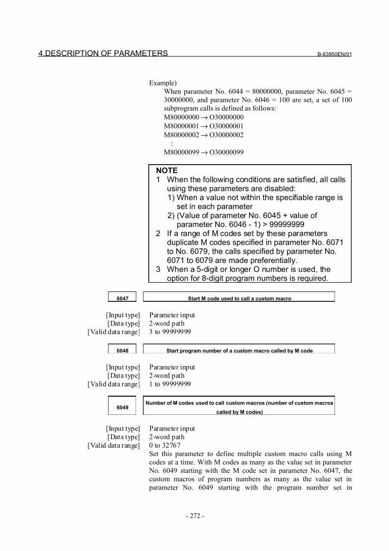
8/21/2019 30i Parameter Manual
http://slidepdf.com/reader/full/30i-parameter-manual 284/493
4.DESCRIPTION OF PARAMETERS B-63950EN/01
- 272 -
Example)
When parameter No. 6044 = 80000000, parameter No. 6045 =
30000000, and parameter No. 6046 = 100 are set, a set of 100
subprogram calls is defined as follows:
M80000000 → O30000000
M80000001 → O30000001
M80000002 → O30000002
:
M80000099 → O30000099
NOTE1 When the following conditions are satisfied, all calls
using these parameters are disabled:1) When a value not within the specifiable range is
set in each parameter 2) (Value of parameter No. 6045 + value of
parameter No. 6046 - 1) > 999999992 If a range of M codes set by these parameters
duplicate M codes specified in parameter No. 6071to No. 6079, the calls specified by parameter No.6071 to 6079 are made preferentially.
3 When a 5-digit or longer O number is used, theoption for 8-digit program numbers is required.
6047 Start M code used to call a custom macro
[Input type] Parameter input
[Data type] 2-word path
[Valid data range] 3 to 99999999
6048 Start program number of a custom macro called by M code
[Input type] Parameter input
[Data type] 2-word path
[Valid data range] 1 to 99999999
6049Number of M codes used to call custom macros (number of custom macros
called by M codes)
[Input type] Parameter input
[Data type] 2-word path
[Valid data range] 0 to 32767
Set this parameter to define multiple custom macro calls using M
codes at a time. With M codes as many as the value set in parameter
No. 6049 starting with the M code set in parameter No. 6047, the
custom macros of program numbers as many as the value set in
parameter No. 6049 starting with the program number set in
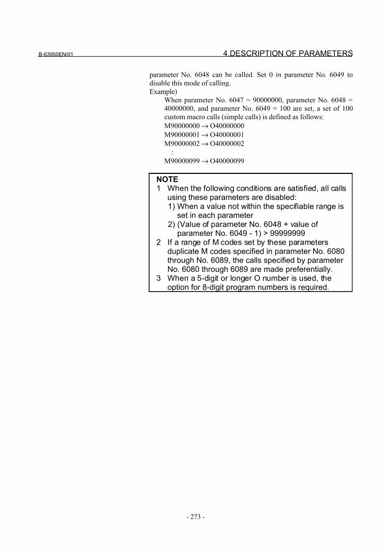
8/21/2019 30i Parameter Manual
http://slidepdf.com/reader/full/30i-parameter-manual 285/493
B-63950EN/01 4.DESCRIPTION OF PARAMETERS
- 273 -
parameter No. 6048 can be called. Set 0 in parameter No. 6049 to
disable this mode of calling.
Example)
When parameter No. 6047 = 90000000, parameter No. 6048 =
40000000, and parameter No. 6049 = 100 are set, a set of 100
custom macro calls (simple calls) is defined as follows:
M90000000 → O40000000
M90000001 → O40000001
M90000002 → O40000002
:
M90000099 → O40000099
NOTE1 When the following conditions are satisfied, all calls
using these parameters are disabled:1) When a value not within the specifiable range is
set in each parameter 2) (Value of parameter No. 6048 + value of
parameter No. 6049 - 1) > 999999992 If a range of M codes set by these parameters
duplicate M codes specified in parameter No. 6080through No. 6089, the calls specified by parameter No. 6080 through 6089 are made preferentially.
3 When a 5-digit or longer O number is used, the
option for 8-digit program numbers is required.
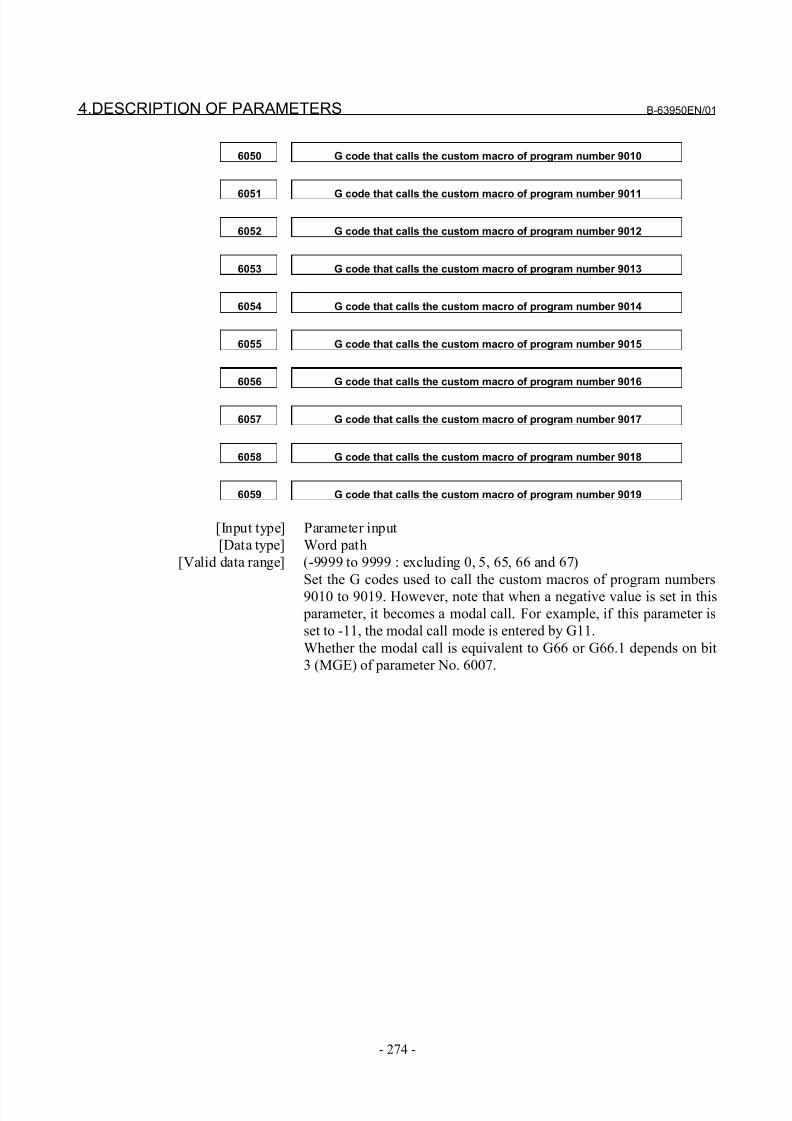
8/21/2019 30i Parameter Manual
http://slidepdf.com/reader/full/30i-parameter-manual 286/493
4.DESCRIPTION OF PARAMETERS B-63950EN/01
- 274 -
6050 G code that calls the custom macro of program number 9010
6051 G code that calls the custom macro of program number 9011
6052 G code that calls the custom macro of program number 9012
6053 G code that calls the custom macro of program number 9013
6054 G code that calls the custom macro of program number 9014
6055 G code that calls the custom macro of program number 9015
6056 G code that calls the custom macro of program number 9016
6057 G code that calls the custom macro of program number 9017
6058 G code that calls the custom macro of program number 9018
6059 G code that calls the custom macro of program number 9019
[Input type] Parameter input
[Data type] Word path
[Valid data range] (-9999 to 9999 : excluding 0, 5, 65, 66 and 67)
Set the G codes used to call the custom macros of program numbers
9010 to 9019. However, note that when a negative value is set in this
parameter, it becomes a modal call. For example, if this parameter is
set to -11, the modal call mode is entered by G11.
Whether the modal call is equivalent to G66 or G66.1 depends on bit
3 (MGE) of parameter No. 6007.
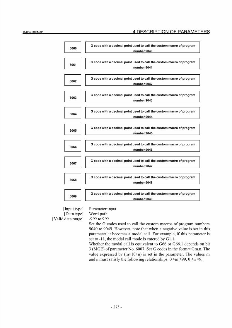
8/21/2019 30i Parameter Manual
http://slidepdf.com/reader/full/30i-parameter-manual 287/493
B-63950EN/01 4.DESCRIPTION OF PARAMETERS
- 275 -
6060G code with a decimal point used to call the custom macro of program
number 9040
6061G code with a decimal point used to call the custom macro of program
number 9041
6062G code with a decimal point used to call the custom macro of program
number 9042
6063G code with a decimal point used to call the custom macro of program
number 9043
6064
G code with a decimal point used to call the custom macro of program
number 9044
6065G code with a decimal point used to call the custom macro of program
number 9045
6066G code with a decimal point used to call the custom macro of program
number 9046
6067G code with a decimal point used to call the custom macro of program
number 9047
6068G code with a decimal point used to call the custom macro of program
number 9048
6069G code with a decimal point used to call the custom macro of program
number 9049
[Input type] Parameter input
[Data type] Word path
[Valid data range] -999 to 999
Set the G codes used to call the custom macros of program numbers
9040 to 9049. However, note that when a negative value is set in this parameter, it becomes a modal call. For example, if this parameter is
set to -11, the modal call mode is entered by G1.1.
Whether the modal call is equivalent to G66 or G66.1 depends on bit
3 (MGE) of parameter No. 6007. Set G codes in the format Gm.n. The
value expressed by (m×10+n) is set in the parameter. The values m
and n must satisfy the following relationships: 0 ≤m ≤99, 0 ≤n ≤9.
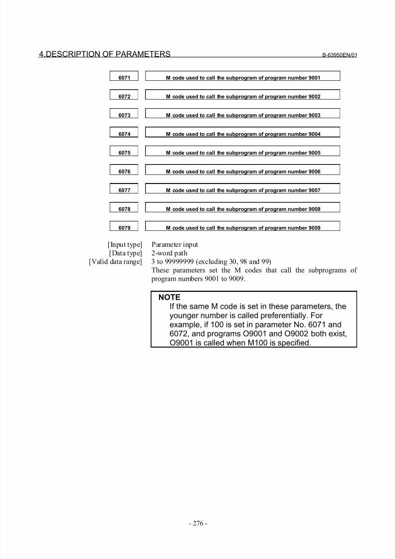
8/21/2019 30i Parameter Manual
http://slidepdf.com/reader/full/30i-parameter-manual 288/493
4.DESCRIPTION OF PARAMETERS B-63950EN/01
- 276 -
6071 M code used to call the subprogram of program number 9001
6072 M code used to call the subprogram of program number 9002
6073 M code used to call the subprogram of program number 9003
6074 M code used to call the subprogram of program number 9004
6075 M code used to call the subprogram of program number 9005
6076 M code used to call the subprogram of program number 9006
6077 M code used to call the subprogram of program number 9007
6078 M code used to call the subprogram of program number 9008
6079 M code used to call the subprogram of program number 9009
[Input type] Parameter input
[Data type] 2-word path
[Valid data range] 3 to 99999999 (excluding 30, 98 and 99)
These parameters set the M codes that call the subprograms of
program numbers 9001 to 9009.
NOTEIf the same M code is set in these parameters, theyounger number is called preferentially. For example, if 100 is set in parameter No. 6071 and6072, and programs O9001 and O9002 both exist,O9001 is called when M100 is specified.
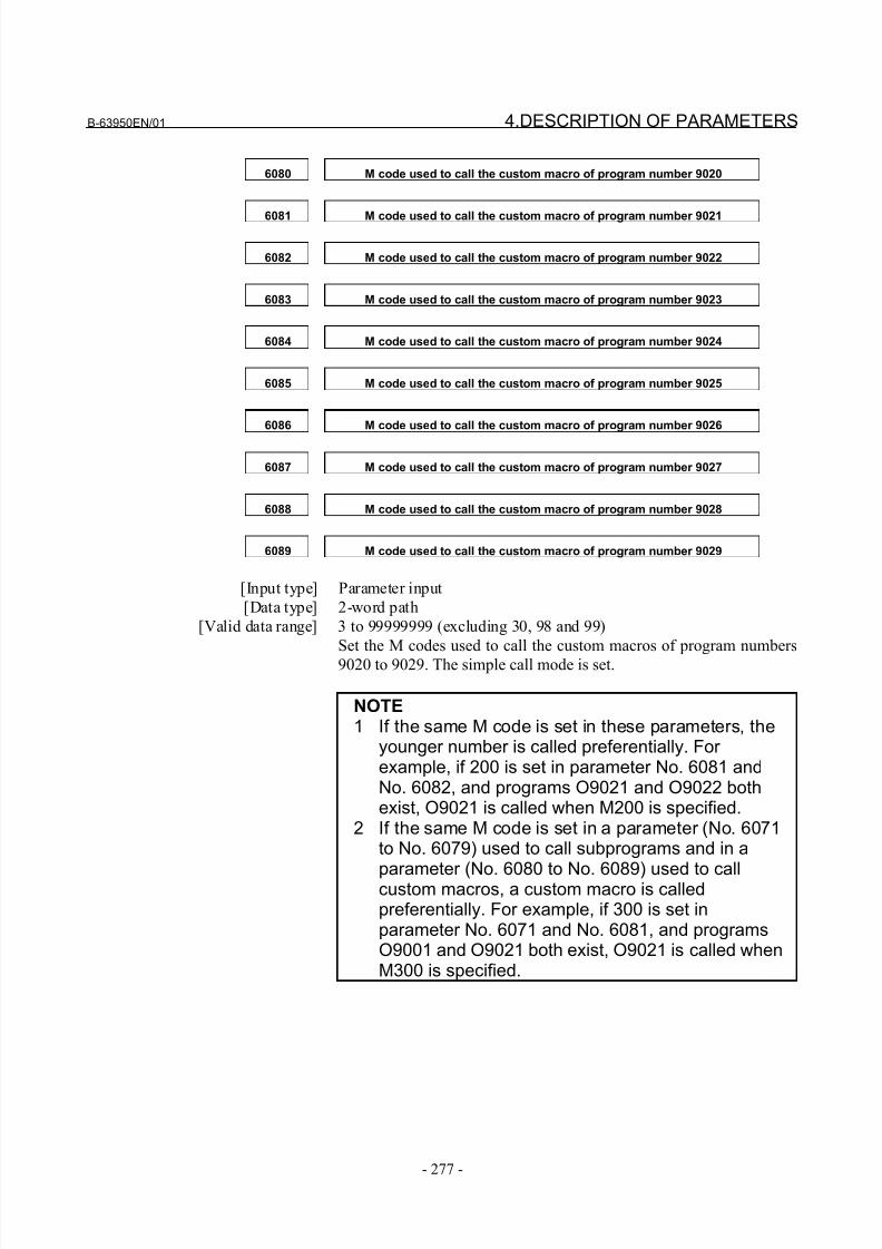
8/21/2019 30i Parameter Manual
http://slidepdf.com/reader/full/30i-parameter-manual 289/493
B-63950EN/01 4.DESCRIPTION OF PARAMETERS
- 277 -
6080 M code used to call the custom macro of program number 9020
6081 M code used to call the custom macro of program number 9021
6082 M code used to call the custom macro of program number 9022
6083 M code used to call the custom macro of program number 9023
6084 M code used to call the custom macro of program number 9024
6085 M code used to call the custom macro of program number 9025
6086 M code used to call the custom macro of program number 9026
6087 M code used to call the custom macro of program number 9027
6088 M code used to call the custom macro of program number 9028
6089 M code used to call the custom macro of program number 9029
[Input type] Parameter input
[Data type] 2-word path
[Valid data range] 3 to 99999999 (excluding 30, 98 and 99)
Set the M codes used to call the custom macros of program numbers
9020 to 9029. The simple call mode is set.
NOTE1 If the same M code is set in these parameters, the
younger number is called preferentially. For example, if 200 is set in parameter No. 6081 andNo. 6082, and programs O9021 and O9022 bothexist, O9021 is called when M200 is specified.
2 If the same M code is set in a parameter (No. 6071to No. 6079) used to call subprograms and in a
parameter (No. 6080 to No. 6089) used to callcustom macros, a custom macro is calledpreferentially. For example, if 300 is set inparameter No. 6071 and No. 6081, and programsO9001 and O9021 both exist, O9021 is called whenM300 is specified.
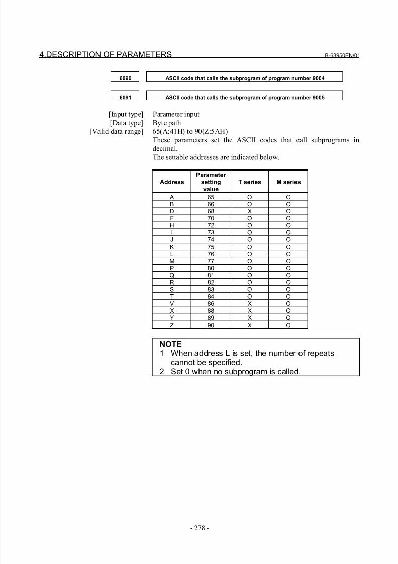
8/21/2019 30i Parameter Manual
http://slidepdf.com/reader/full/30i-parameter-manual 290/493
4.DESCRIPTION OF PARAMETERS B-63950EN/01
- 278 -
6090 ASCII code that calls the subprogram of program number 9004
6091 ASCII code that calls the subprogram of program number 9005
[Input type] Parameter input
[Data type] Byte path
[Valid data range] 65(A:41H) to 90(Z:5AH)
These parameters set the ASCII codes that call subprograms in
decimal.
The settable addresses are indicated below.
AddressParameter
setting
value
T series M series
A 65 O OB 66 O OD 68 X OF 70 O OH 72 O OI 73 O OJ 74 O OK 75 O OL 76 O OM 77 O OP 80 O OQ 81 O OR 82 O OS 83 O O
T 84 O OV 86 X OX 88 X OY 89 X OZ 90 X O
NOTE1 When address L is set, the number of repeats
cannot be specified.2 Set 0 when no subprogram is called.
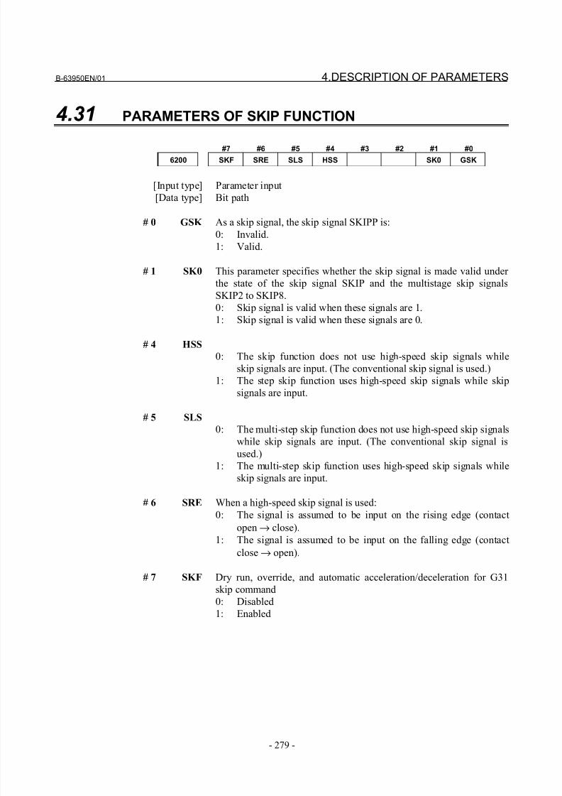
8/21/2019 30i Parameter Manual
http://slidepdf.com/reader/full/30i-parameter-manual 291/493
B-63950EN/01 4.DESCRIPTION OF PARAMETERS
- 279 -
4.31 PARAMETERS OF SKIP FUNCTION
#7 #6 #5 #4 #3 #2 #1 #0
6200 SKF SRE SLS HSS SK0 GSK
[Input type] Parameter input
[Data type] Bit path
# 0 GSK As a skip signal, the skip signal SKIPP is:
0: Invalid.
1: Valid.
# 1 SK0 This parameter specifies whether the skip signal is made valid under
the state of the skip signal SKIP and the multistage skip signals
SKIP2 to SKIP8.
0: Skip signal is valid when these signals are 1.
1: Skip signal is valid when these signals are 0.
# 4 HSS
0: The skip function does not use high-speed skip signals while
skip signals are input. (The conventional skip signal is used.)
1: The step skip function uses high-speed skip signals while skip
signals are input.
# 5 SLS0: The multi-step skip function does not use high-speed skip signals
while skip signals are input. (The conventional skip signal is
used.)
1: The multi-step skip function uses high-speed skip signals while
skip signals are input.
# 6 SRE When a high-speed skip signal is used:
0: The signal is assumed to be input on the rising edge (contact
open → close).
1: The signal is assumed to be input on the falling edge (contact
close → open).
# 7 SKF Dry run, override, and automatic acceleration/deceleration for G31
skip command
0: Disabled
1: Enabled
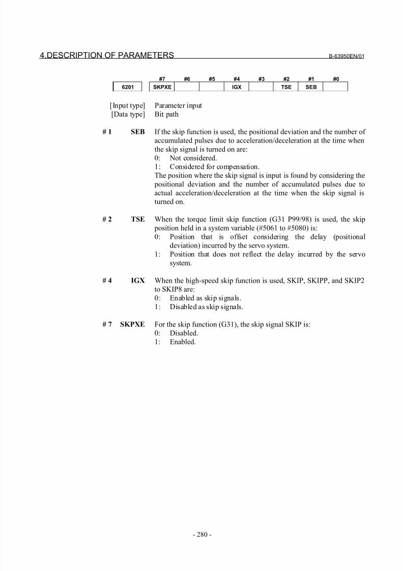
8/21/2019 30i Parameter Manual
http://slidepdf.com/reader/full/30i-parameter-manual 292/493
4.DESCRIPTION OF PARAMETERS B-63950EN/01
- 280 -
#7 #6 #5 #4 #3 #2 #1 #0
6201 SKPXE IGX TSE SEB
[Input type] Parameter input
[Data type] Bit path
# 1 SEB If the skip function is used, the positional deviation and the number of
accumulated pulses due to acceleration/deceleration at the time when
the skip signal is turned on are:
0: Not considered.
1: Considered for compensation.
The position where the skip signal is input is found by considering the
positional deviation and the number of accumulated pulses due to
actual acceleration/deceleration at the time when the skip signal is
turned on.
# 2 TSE When the torque limit skip function (G31 P99/98) is used, the skip
position held in a system variable (#5061 to #5080) is:
0: Position that is offset considering the delay (positional
deviation) incurred by the servo system.
1: Position that does not reflect the delay incurred by the servo
system.
# 4 IGX When the high-speed skip function is used, SKIP, SKIPP, and SKIP2
to SKIP8 are:
0: Enabled as skip signals.1: Disabled as skip signals.
# 7 SKPXE For the skip function (G31), the skip signal SKIP is:
0: Disabled.
1: Enabled.
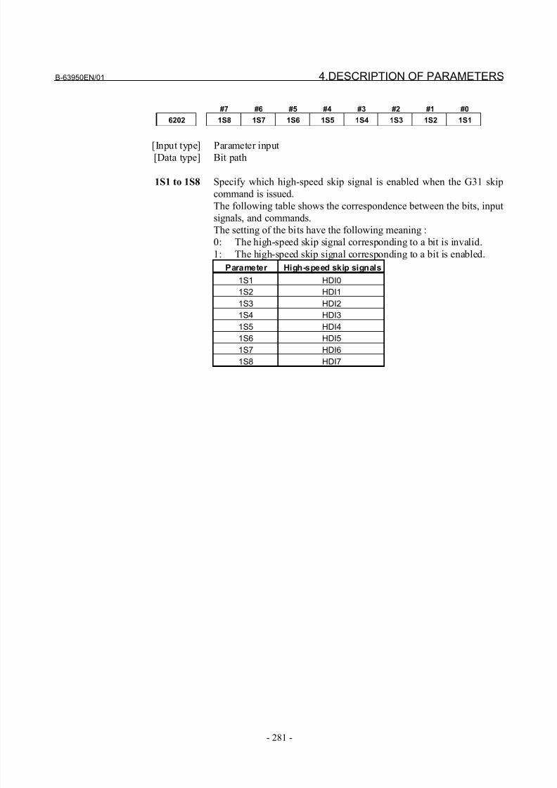
8/21/2019 30i Parameter Manual
http://slidepdf.com/reader/full/30i-parameter-manual 293/493
B-63950EN/01 4.DESCRIPTION OF PARAMETERS
- 281 -
#7 #6 #5 #4 #3 #2 #1 #0
6202 1S8 1S7 1S6 1S5 1S4 1S3 1S2 1S1
[Input type] Parameter input
[Data type] Bit path
1S1 to 1S8 Specify which high-speed skip signal is enabled when the G31 skip
command is issued.
The following table shows the correspondence between the bits, input
signals, and commands.
The setting of the bits have the following meaning :
0: The high-speed skip signal corresponding to a bit is invalid.
1: The high-speed skip signal corresponding to a bit is enabled.
Parameter High-speed skip signals
1S1 HDI0
1S2 HDI1
1S3 HDI2
1S4 HDI3
1S5 HDI4
1S6 HDI5
1S7 HDI6
1S8 HDI7
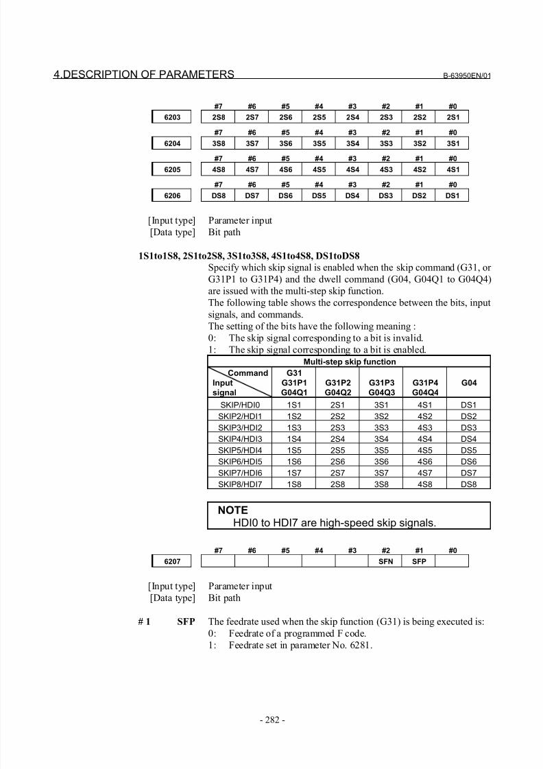
8/21/2019 30i Parameter Manual
http://slidepdf.com/reader/full/30i-parameter-manual 294/493
4.DESCRIPTION OF PARAMETERS B-63950EN/01
- 282 -
#7 #6 #5 #4 #3 #2 #1 #0
6203 2S8 2S7 2S6 2S5 2S4 2S3 2S2 2S1
#7 #6 #5 #4 #3 #2 #1 #06204 3S8 3S7 3S6 3S5 3S4 3S3 3S2 3S1
#7 #6 #5 #4 #3 #2 #1 #0
6205 4S8 4S7 4S6 4S5 4S4 4S3 4S2 4S1
#7 #6 #5 #4 #3 #2 #1 #0
6206 DS8 DS7 DS6 DS5 DS4 DS3 DS2 DS1
[Input type] Parameter input
[Data type] Bit path
1S1to1S8, 2S1to2S8, 3S1to3S8, 4S1to4S8, DS1toDS8
Specify which skip signal is enabled when the skip command (G31, or G31P1 to G31P4) and the dwell command (G04, G04Q1 to G04Q4)
are issued with the multi-step skip function.
The following table shows the correspondence between the bits, input
signals, and commands.
The setting of the bits have the following meaning :
0: The skip signal corresponding to a bit is invalid.
1: The skip signal corresponding to a bit is enabled.
Multi-step skip function
Command
Inputsignal
G31
G31P1G04Q1
G31P2G04Q2
G31P3G04Q3
G31P4G04Q4
G04
SKIP/HDI0 1S1 2S1 3S1 4S1 DS1SKIP2/HDI1 1S2 2S2 3S2 4S2 DS2
SKIP3/HDI2 1S3 2S3 3S3 4S3 DS3
SKIP4/HDI3 1S4 2S4 3S4 4S4 DS4
SKIP5/HDI4 1S5 2S5 3S5 4S5 DS5
SKIP6/HDI5 1S6 2S6 3S6 4S6 DS6
SKIP7/HDI6 1S7 2S7 3S7 4S7 DS7
SKIP8/HDI7 1S8 2S8 3S8 4S8 DS8
NOTEHDI0 to HDI7 are high-speed skip signals.
#7 #6 #5 #4 #3 #2 #1 #0
6207 SFN SFP
[Input type] Parameter input
[Data type] Bit path
# 1 SFP The feedrate used when the skip function (G31) is being executed is:
0: Feedrate of a programmed F code.
1: Feedrate set in parameter No. 6281.
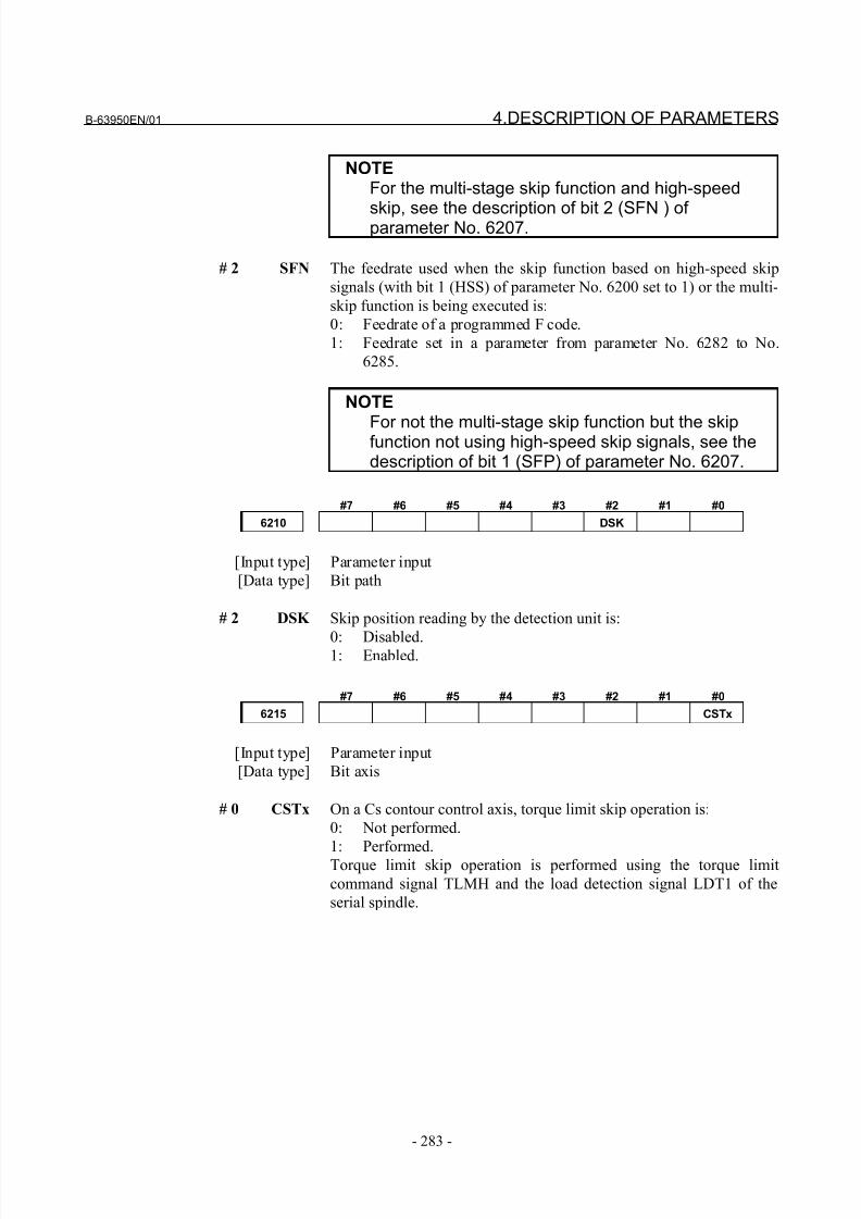
8/21/2019 30i Parameter Manual
http://slidepdf.com/reader/full/30i-parameter-manual 295/493
B-63950EN/01 4.DESCRIPTION OF PARAMETERS
- 283 -
NOTEFor the multi-stage skip function and high-speed
skip, see the description of bit 2 (SFN ) of parameter No. 6207.
# 2 SFN The feedrate used when the skip function based on high-speed skip
signals (with bit 1 (HSS) of parameter No. 6200 set to 1) or the multi-
skip function is being executed is:
0: Feedrate of a programmed F code.
1: Feedrate set in a parameter from parameter No. 6282 to No.
6285.
NOTE
For not the multi-stage skip function but the skipfunction not using high-speed skip signals, see thedescription of bit 1 (SFP) of parameter No. 6207.
#7 #6 #5 #4 #3 #2 #1 #0
6210 DSK
[Input type] Parameter input
[Data type] Bit path
# 2 DSK Skip position reading by the detection unit is:
0: Disabled.1: Enabled.
#7 #6 #5 #4 #3 #2 #1 #0
6215 CSTx
[Input type] Parameter input
[Data type] Bit axis
# 0 CSTx On a Cs contour control axis, torque limit skip operation is:
0: Not performed.
1: Performed.Torque limit skip operation is performed using the torque limit
command signal TLMH and the load detection signal LDT1 of the
serial spindle.
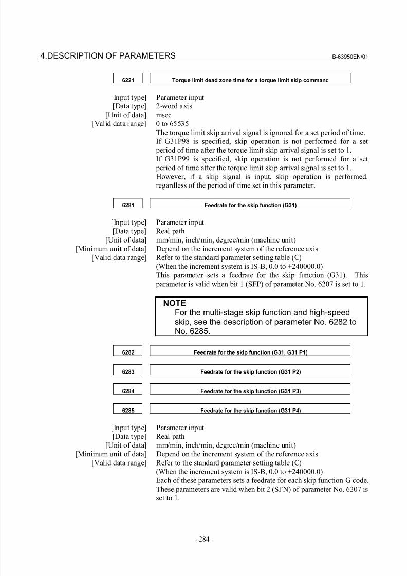
8/21/2019 30i Parameter Manual
http://slidepdf.com/reader/full/30i-parameter-manual 296/493
4.DESCRIPTION OF PARAMETERS B-63950EN/01
- 284 -
6221 Torque limit dead zone time for a torque limit skip command
[Input type] Parameter input[Data type] 2-word axis
[Unit of data] msec
[Valid data range] 0 to 65535
The torque limit skip arrival signal is ignored for a set period of time.
If G31P98 is specified, skip operation is not performed for a set
period of time after the torque limit skip arrival signal is set to 1.
If G31P99 is specified, skip operation is not performed for a set
period of time after the torque limit skip arrival signal is set to 1.
However, if a skip signal is input, skip operation is performed,
regardless of the period of time set in this parameter.
6281 Feedrate for the skip function (G31)
[Input type] Parameter input
[Data type] Real path
[Unit of data] mm/min, inch/min, degree/min (machine unit)
[Minimum unit of data] Depend on the increment system of the reference axis
[Valid data range] Refer to the standard parameter setting table (C)
(When the increment system is IS-B, 0.0 to +240000.0)
This parameter sets a feedrate for the skip function (G31). This
parameter is valid when bit 1 (SFP) of parameter No. 6207 is set to 1.
NOTEFor the multi-stage skip function and high-speedskip, see the description of parameter No. 6282 toNo. 6285.
6282 Feedrate for the skip function (G31, G31 P1)
6283 Feedrate for the skip function (G31 P2)
6284 Feedrate for the skip function (G31 P3)
6285 Feedrate for the skip function (G31 P4)
[Input type] Parameter input
[Data type] Real path
[Unit of data] mm/min, inch/min, degree/min (machine unit)
[Minimum unit of data] Depend on the increment system of the reference axis
[Valid data range] Refer to the standard parameter setting table (C)
(When the increment system is IS-B, 0.0 to +240000.0)
Each of these parameters sets a feedrate for each skip function G code.
These parameters are valid when bit 2 (SFN) of parameter No. 6207 is
set to 1.
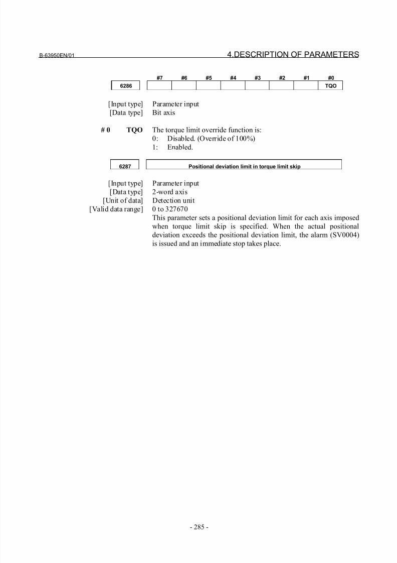
8/21/2019 30i Parameter Manual
http://slidepdf.com/reader/full/30i-parameter-manual 297/493
B-63950EN/01 4.DESCRIPTION OF PARAMETERS
- 285 -
#7 #6 #5 #4 #3 #2 #1 #0
6286 TQO
[Input type] Parameter input
[Data type] Bit axis
# 0 TQO The torque limit override function is:
0: Disabled. (Override of 100%)
1: Enabled.
6287 Positional deviation limit in torque limit skip
[Input type] Parameter input
[Data type] 2-word axis
[Unit of data] Detection unit
[Valid data range] 0 to 327670
This parameter sets a positional deviation limit for each axis imposed
when torque limit skip is specified. When the actual positional
deviation exceeds the positional deviation limit, the alarm (SV0004)
is issued and an immediate stop takes place.
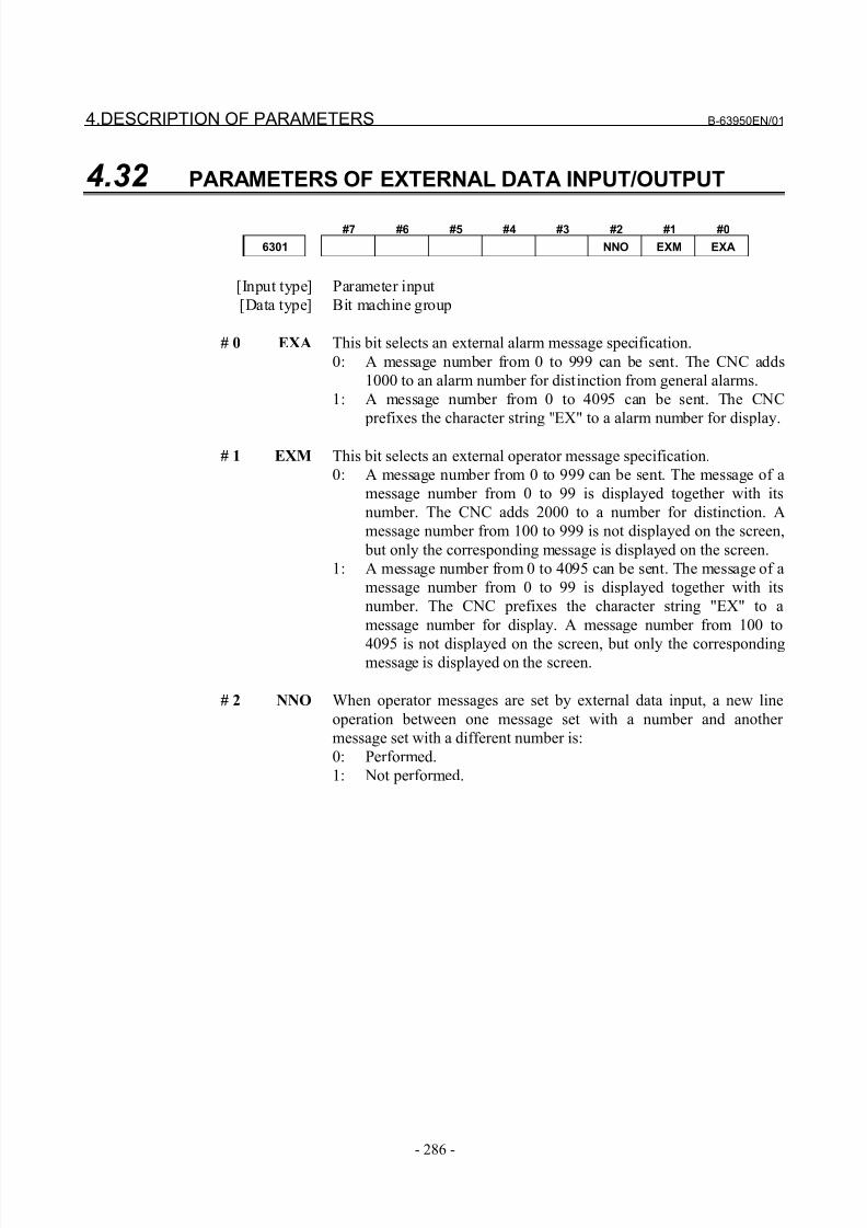
8/21/2019 30i Parameter Manual
http://slidepdf.com/reader/full/30i-parameter-manual 298/493
4.DESCRIPTION OF PARAMETERS B-63950EN/01
- 286 -
4.32 PARAMETERS OF EXTERNAL DATA INPUT/OUTPUT
#7 #6 #5 #4 #3 #2 #1 #0
6301 NNO EXM EXA
[Input type] Parameter input
[Data type] Bit machine group
# 0 EXA This bit selects an external alarm message specification.
0: A message number from 0 to 999 can be sent. The CNC adds
1000 to an alarm number for distinction from general alarms.
1: A message number from 0 to 4095 can be sent. The CNC
prefixes the character string "EX" to a alarm number for display.
# 1 EXM This bit selects an external operator message specification.
0: A message number from 0 to 999 can be sent. The message of a
message number from 0 to 99 is displayed together with its
number. The CNC adds 2000 to a number for distinction. A
message number from 100 to 999 is not displayed on the screen,
but only the corresponding message is displayed on the screen.
1: A message number from 0 to 4095 can be sent. The message of a
message number from 0 to 99 is displayed together with its
number. The CNC prefixes the character string "EX" to a
message number for display. A message number from 100 to
4095 is not displayed on the screen, but only the correspondingmessage is displayed on the screen.
# 2 NNO When operator messages are set by external data input, a new line
operation between one message set with a number and another
message set with a different number is:
0: Performed.
1: Not performed.
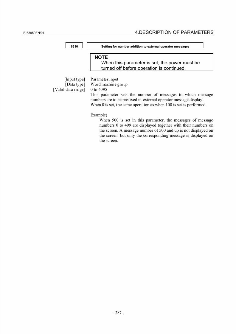
8/21/2019 30i Parameter Manual
http://slidepdf.com/reader/full/30i-parameter-manual 299/493
B-63950EN/01 4.DESCRIPTION OF PARAMETERS
- 287 -
6310 Setting for number addition to external operator messages
NOTEWhen this parameter is set, the power must beturned off before operation is continued.
[Input type] Parameter input
[Data type] Word machine group
[Valid data range] 0 to 4095
This parameter sets the number of messages to which message
numbers are to be prefixed in external operator message display.
When 0 is set, the same operation as when 100 is set is performed.
Example)When 500 is set in this parameter, the messages of message
numbers 0 to 499 are displayed together with their numbers on
the screen. A message number of 500 and up is not displayed on
the screen, but only the corresponding message is displayed on
the screen.
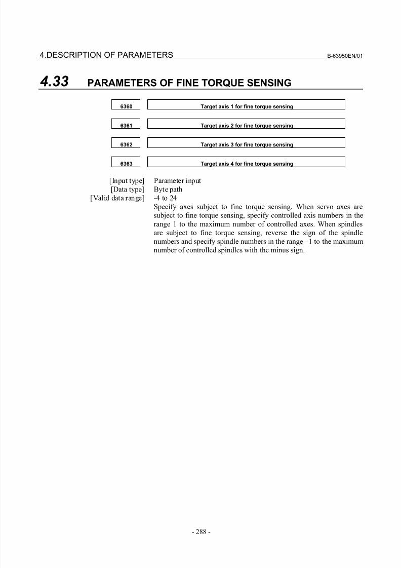
8/21/2019 30i Parameter Manual
http://slidepdf.com/reader/full/30i-parameter-manual 300/493
4.DESCRIPTION OF PARAMETERS B-63950EN/01
- 288 -
4.33 PARAMETERS OF FINE TORQUE SENSING
6360 Target axis 1 for fine torque sensing
6361 Target axis 2 for fine torque sensing
6362 Target axis 3 for fine torque sensing
6363 Target axis 4 for fine torque sensing
[Input type] Parameter input
[Data type] Byte path
[Valid data range] -4 to 24Specify axes subject to fine torque sensing. When servo axes are
subject to fine torque sensing, specify controlled axis numbers in the
range 1 to the maximum number of controlled axes. When spindles
are subject to fine torque sensing, reverse the sign of the spindle
numbers and specify spindle numbers in the range –1 to the maximum
number of controlled spindles with the minus sign.

8/21/2019 30i Parameter Manual
http://slidepdf.com/reader/full/30i-parameter-manual 301/493
B-63950EN/01 4.DESCRIPTION OF PARAMETERS
- 289 -
4.34 PARAMETERS OF GRAPHIC DISPLAY
4.34.1 Parameters of Graphic Display/Dynamic Graphic Display
6510 Specifying the graphic coordinate system
[Input type] Parameter input
[Data type] Byte path
[Valid data range] 1 to 12
Specify the graphic coordinate system in tool path drawing.
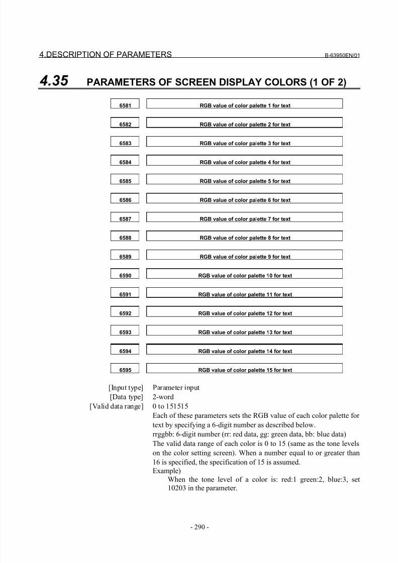
8/21/2019 30i Parameter Manual
http://slidepdf.com/reader/full/30i-parameter-manual 302/493
4.DESCRIPTION OF PARAMETERS B-63950EN/01
- 290 -
4.35 PARAMETERS OF SCREEN DISPLAY COLORS (1 OF 2)
6581 RGB value of color palette 1 for text
6582 RGB value of color palette 2 for text
6583 RGB value of color palette 3 for text
6584 RGB value of color palette 4 for text
6585 RGB value of color palette 5 for text
6586 RGB value of color palette 6 for text
6587 RGB value of color palette 7 for text
6588 RGB value of color palette 8 for text
6589 RGB value of color palette 9 for text
6590 RGB value of color palette 10 for text
6591 RGB value of color palette 11 for text
6592 RGB value of color palette 12 for text
6593 RGB value of color palette 13 for text
6594 RGB value of color palette 14 for text
6595 RGB value of color palette 15 for text
[Input type] Parameter input
[Data type] 2-word
[Valid data range] 0 to 151515
Each of these parameters sets the RGB value of each color palette for
text by specifying a 6-digit number as described below.
rrggbb: 6-digit number (rr: red data, gg: green data, bb: blue data)
The valid data range of each color is 0 to 15 (same as the tone levels
on the color setting screen). When a number equal to or greater than
16 is specified, the specification of 15 is assumed.
Example)
When the tone level of a color is: red:1 green:2, blue:3, set
10203 in the parameter.
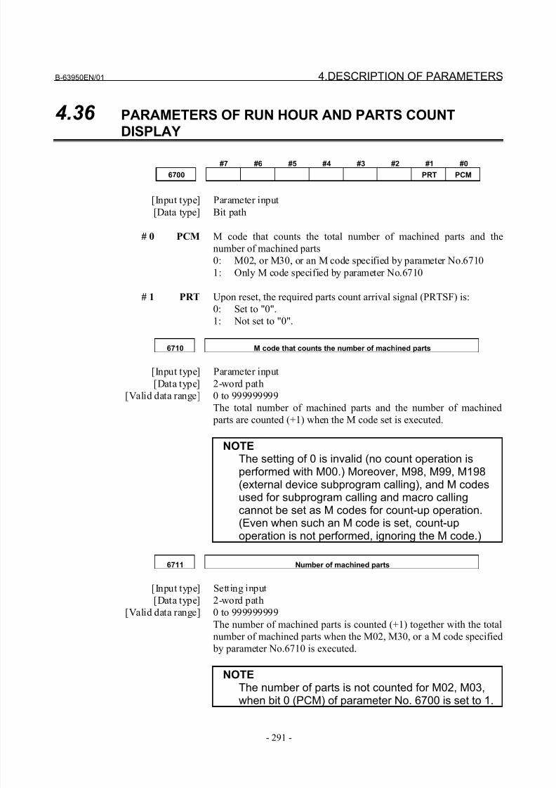
8/21/2019 30i Parameter Manual
http://slidepdf.com/reader/full/30i-parameter-manual 303/493
B-63950EN/01 4.DESCRIPTION OF PARAMETERS
- 291 -
4.36 PARAMETERS OF RUN HOUR AND PARTS COUNT
DISPLAY
#7 #6 #5 #4 #3 #2 #1 #0
6700 PRT PCM
[Input type] Parameter input
[Data type] Bit path
# 0 PCM M code that counts the total number of machined parts and the
number of machined parts
0: M02, or M30, or an M code specified by parameter No.6710
1: Only M code specified by parameter No.6710
# 1 PRT Upon reset, the required parts count arrival signal (PRTSF) is:
0: Set to "0".
1: Not set to "0".
6710 M code that counts the number of machined parts
[Input type] Parameter input
[Data type] 2-word path
[Valid data range] 0 to 999999999
The total number of machined parts and the number of machined
parts are counted (+1) when the M code set is executed.
NOTEThe setting of 0 is invalid (no count operation isperformed with M00.) Moreover, M98, M99, M198(external device subprogram calling), and M codesused for subprogram calling and macro callingcannot be set as M codes for count-up operation.(Even when such an M code is set, count-upoperation is not performed, ignoring the M code.)
6711 Number of machined parts
[Input type] Setting input
[Data type] 2-word path
[Valid data range] 0 to 999999999
The number of machined parts is counted (+1) together with the total
number of machined parts when the M02, M30, or a M code specified
by parameter No.6710 is executed.
NOTE
The number of parts is not counted for M02, M03,when bit 0 (PCM) of parameter No. 6700 is set to 1.
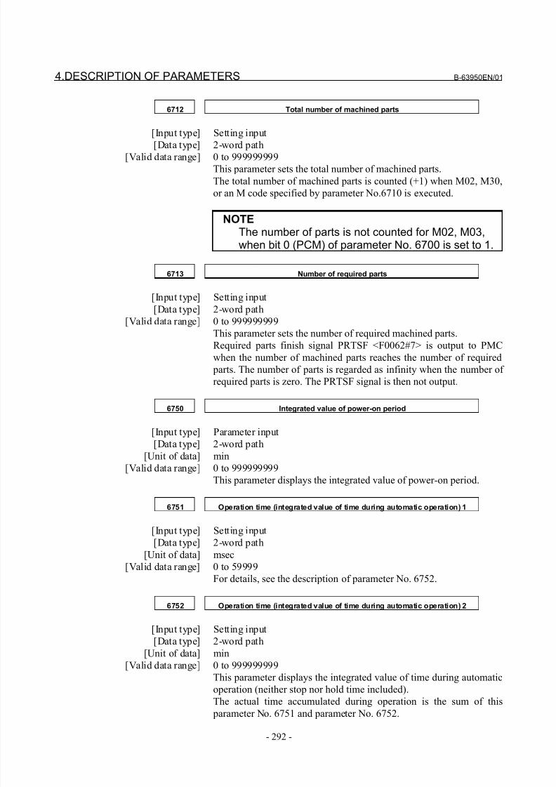
8/21/2019 30i Parameter Manual
http://slidepdf.com/reader/full/30i-parameter-manual 304/493
4.DESCRIPTION OF PARAMETERS B-63950EN/01
- 292 -
6712 Total number of machined parts
[Input type] Setting input[Data type] 2-word path
[Valid data range] 0 to 999999999
This parameter sets the total number of machined parts.
The total number of machined parts is counted (+1) when M02, M30,
or an M code specified by parameter No.6710 is executed.
NOTEThe number of parts is not counted for M02, M03,when bit 0 (PCM) of parameter No. 6700 is set to 1.
6713 Number of required parts
[Input type] Setting input
[Data type] 2-word path
[Valid data range] 0 to 999999999
This parameter sets the number of required machined parts.
Required parts finish signal PRTSF <F0062#7> is output to PMC
when the number of machined parts reaches the number of required
parts. The number of parts is regarded as infinity when the number of
required parts is zero. The PRTSF signal is then not output.
6750 Integrated value of power-on period
[Input type] Parameter input
[Data type] 2-word path
[Unit of data] min
[Valid data range] 0 to 999999999
This parameter displays the integrated value of power-on period.
6751 Operation time (integrated value of time during automatic operation) 1
[Input type] Setting input
[Data type] 2-word path
[Unit of data] msec[Valid data range] 0 to 59999
For details, see the description of parameter No. 6752.
6752 Operation time (integrated value of time during automatic operation) 2
[Input type] Setting input
[Data type] 2-word path
[Unit of data] min
[Valid data range] 0 to 999999999
This parameter displays the integrated value of time during automatic
operation (neither stop nor hold time included).The actual time accumulated during operation is the sum of this
parameter No. 6751 and parameter No. 6752.
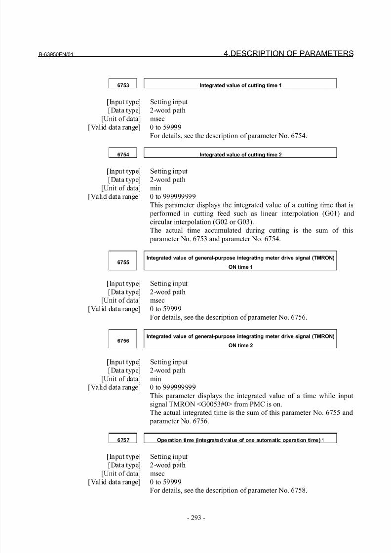
8/21/2019 30i Parameter Manual
http://slidepdf.com/reader/full/30i-parameter-manual 305/493
B-63950EN/01 4.DESCRIPTION OF PARAMETERS
- 293 -
6753 Integrated value of cutting time 1
[Input type] Setting input
[Data type] 2-word path
[Unit of data] msec
[Valid data range] 0 to 59999
For details, see the description of parameter No. 6754.
6754 Integrated value of cutting time 2
[Input type] Setting input
[Data type] 2-word path
[Unit of data] min
[Valid data range] 0 to 999999999
This parameter displays the integrated value of a cutting time that is
performed in cutting feed such as linear interpolation (G01) and
circular interpolation (G02 or G03).
The actual time accumulated during cutting is the sum of this
parameter No. 6753 and parameter No. 6754.
6755Integrated value of general-purpose integrating meter drive signal (TMRON)
ON time 1
[Input type] Setting input
[Data type] 2-word path[Unit of data] msec
[Valid data range] 0 to 59999
For details, see the description of parameter No. 6756.
6756Integrated value of general-purpose integrating meter drive signal (TMRON)
ON time 2
[Input type] Setting input
[Data type] 2-word path
[Unit of data] min
[Valid data range] 0 to 999999999This parameter displays the integrated value of a time while input
signal TMRON <G0053#0> from PMC is on.
The actual integrated time is the sum of this parameter No. 6755 and
parameter No. 6756.
6757 Operation time (integrated value of one automatic operation time) 1
[Input type] Setting input
[Data type] 2-word path
[Unit of data] msec
[Valid data range] 0 to 59999For details, see the description of parameter No. 6758.
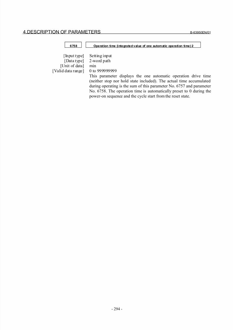
8/21/2019 30i Parameter Manual
http://slidepdf.com/reader/full/30i-parameter-manual 306/493
4.DESCRIPTION OF PARAMETERS B-63950EN/01
- 294 -
6758 Operation time (integrated value of one automatic operation time) 2
[Input type] Setting input[Data type] 2-word path
[Unit of data] min
[Valid data range] 0 to 999999999
This parameter displays the one automatic operation drive time
(neither stop nor hold state included). The actual time accumulated
during operating is the sum of this parameter No. 6757 and parameter
No. 6758. The operation time is automatically preset to 0 during the
power-on sequence and the cycle start from the reset state.
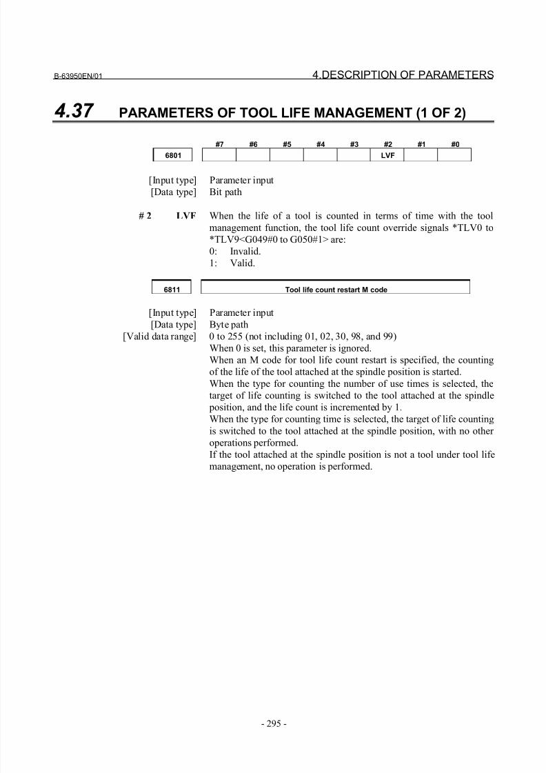
8/21/2019 30i Parameter Manual
http://slidepdf.com/reader/full/30i-parameter-manual 307/493
B-63950EN/01 4.DESCRIPTION OF PARAMETERS
- 295 -
4.37 PARAMETERS OF TOOL LIFE MANAGEMENT (1 OF 2)
#7 #6 #5 #4 #3 #2 #1 #0
6801 LVF
[Input type] Parameter input
[Data type] Bit path
# 2 LVF When the life of a tool is counted in terms of time with the tool
management function, the tool life count override signals *TLV0 to
*TLV9<G049#0 to G050#1> are:
0: Invalid.
1: Valid.
6811 Tool life count restart M code
[Input type] Parameter input
[Data type] Byte path
[Valid data range] 0 to 255 (not including 01, 02, 30, 98, and 99)
When 0 is set, this parameter is ignored.
When an M code for tool life count restart is specified, the counting
of the life of the tool attached at the spindle position is started.
When the type for counting the number of use times is selected, the
target of life counting is switched to the tool attached at the spindle
position, and the life count is incremented by 1.When the type for counting time is selected, the target of life counting
is switched to the tool attached at the spindle position, with no other
operations performed.
If the tool attached at the spindle position is not a tool under tool life
management, no operation is performed.
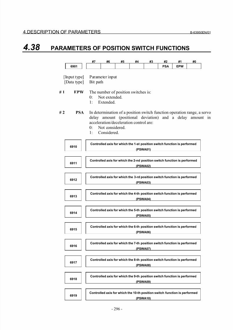
8/21/2019 30i Parameter Manual
http://slidepdf.com/reader/full/30i-parameter-manual 308/493
4.DESCRIPTION OF PARAMETERS B-63950EN/01
- 296 -
4.38 PARAMETERS OF POSITION SWITCH FUNCTIONS
#7 #6 #5 #4 #3 #2 #1 #0
6901 PSA EPW
[Input type] Parameter input
[Data type] Bit path
# 1 EPW The number of position switches is:
0: Not extended.
1: Extended.
# 2 PSA In determination of a position switch function operation range, a servo
delay amount (positional deviation) and a delay amount in
acceleration/deceleration control are:
0: Not considered.
1: Considered.
6910Controlled axis for which the 1-st position switch function is performed
(PSWA01)
6911Controlled axis for which the 2-nd position switch function is performed
(PSWA02)
6912Controlled axis for which the 3-rd position switch function is performed
(PSWA03)
6913Controlled axis for which the 4-th position switch function is performed
(PSWA04)
6914Controlled axis for which the 5-th position switch function is performed
(PSWA05)
6915Controlled axis for which the 6-th position switch function is performed
(PSWA06)
6916Controlled axis for which the 7-th position switch function is performed
(PSWA07)
6917Controlled axis for which the 8-th position switch function is performed
(PSWA08)
6918Controlled axis for which the 9-th position switch function is performed
(PSWA09)
6919Controlled axis for which the 10-th position switch function is performed
(PSWA10)
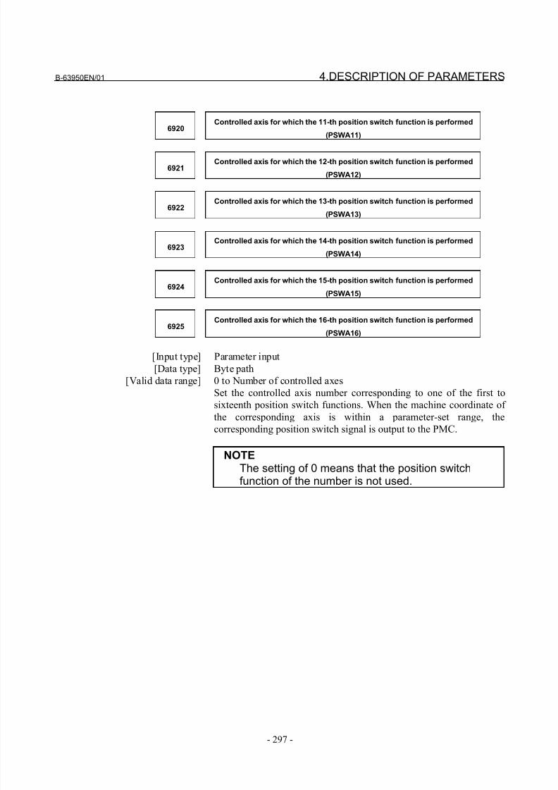
8/21/2019 30i Parameter Manual
http://slidepdf.com/reader/full/30i-parameter-manual 309/493
B-63950EN/01 4.DESCRIPTION OF PARAMETERS
- 297 -
6920Controlled axis for which the 11-th position switch function is performed
(PSWA11)
6921Controlled axis for which the 12-th position switch function is performed
(PSWA12)
6922Controlled axis for which the 13-th position switch function is performed
(PSWA13)
6923Controlled axis for which the 14-th position switch function is performed
(PSWA14)
6924Controlled axis for which the 15-th position switch function is performed
(PSWA15)
6925Controlled axis for which the 16-th position switch function is performed
(PSWA16)
[Input type] Parameter input
[Data type] Byte path
[Valid data range] 0 to Number of controlled axes
Set the controlled axis number corresponding to one of the first to
sixteenth position switch functions. When the machine coordinate of
the corresponding axis is within a parameter-set range, thecorresponding position switch signal is output to the PMC.
NOTEThe setting of 0 means that the position switchfunction of the number is not used.
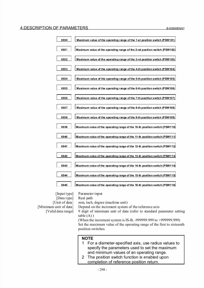
8/21/2019 30i Parameter Manual
http://slidepdf.com/reader/full/30i-parameter-manual 310/493
4.DESCRIPTION OF PARAMETERS B-63950EN/01
- 298 -
6930 Maximum value of the operating range of the 1-st position switch (PSW101)
6931 Maximum value of the operating range of the 2-nd position switch (PSW102)
6932 Maximum value of the operating range of the 3-rd position switch (PSW103)
6933 Maximum value of the operating range of the 4-th position switch (PSW104)
6934 Maximum value of the operating range of the 5-th position switch (PSW105)
6935 Maximum value of the operating range of the 6-th position switch (PSW106)
6936 Maximum value of the operating range of the 7-th position switch (PSW107)
6937 Maximum value of the operating range of the 8-th position switch (PSW108)
6938 Maximum value of the operating range of the 9-th position switch (PSW109)
6939 Maximum value of the operating range of the 10-th position switch (PSW110)
6940 Maximum value of the operating range of the 11-th position switch (PSW111)
6941 Maximum value of the operating range of the 12-th position switch (PSW112)
6942 Maximum value of the operating range of the 13-th position switch (PSW113)
6943 Maximum value of the operating range of the 14-th position switch (PSW114)
6944 Maximum value of the operating range of the 15-th position switch (PSW115)
6945 Maximum value of the operating range of the 16-th position switch (PSW116)
[Input type] Parameter input
[Data type] Real path
[Unit of data] mm, inch, degree (machine unit)[Minimum unit of data] Depend on the increment system of the reference axis
[Valid data range] 9 digit of minimum unit of data (refer to standard parameter setting
table (A) )
(When the increment system is IS-B, -999999.999 to +999999.999)
Set the maximum value of the operating range of the first to sixteenth
position switches.
NOTE1 For a diameter-specified axis, use radius values to
specify the parameters used to set the maximum
and minimum values of an operating range.2 The position switch function is enabled upon
completion of reference position return.
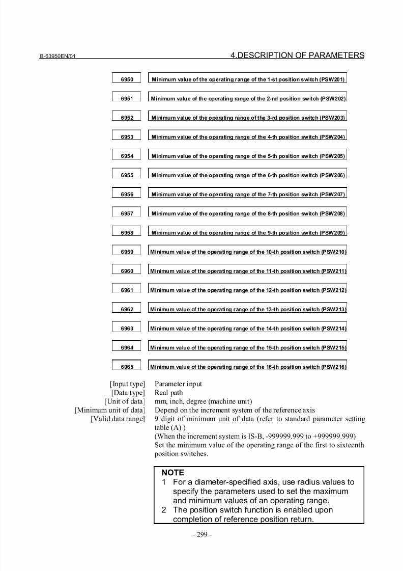
8/21/2019 30i Parameter Manual
http://slidepdf.com/reader/full/30i-parameter-manual 311/493
B-63950EN/01 4.DESCRIPTION OF PARAMETERS
- 299 -
6950 Minimum value of the operating range of the 1-st position switch (PSW201)
6951 Minimum value of the operating range of the 2-nd position switch (PSW202)
6952 Minimum value of the operating range of the 3-rd position switch (PSW203)
6953 Minimum value of the operating range of the 4-th position switch (PSW204)
6954 Minimum value of the operating range of the 5-th position switch (PSW205)
6955 Minimum value of the operating range of the 6-th position switch (PSW206)
6956 Minimum value of the operating range of the 7-th position switch (PSW207)
6957 Minimum value of the operating range of the 8-th position switch (PSW208)
6958 Minimum value of the operating range of the 9-th position switch (PSW209)
6959 Minimum value of the operating range of the 10-th position switch (PSW210)
6960 Minimum value of the operating range of the 11-th position switch (PSW211)
6961 Minimum value of the operating range of the 12-th position switch (PSW212)
6962 Minimum value of the operating range of the 13-th position switch (PSW213)
6963 Minimum value of the operating range of the 14-th position switch (PSW214)
6964 Minimum value of the operating range of the 15-th position switch (PSW215)
6965 Minimum value of the operating range of the 16-th position switch (PSW216)
[Input type] Parameter input
[Data type] Real path
[Unit of data] mm, inch, degree (machine unit)[Minimum unit of data] Depend on the increment system of the reference axis
[Valid data range] 9 digit of minimum unit of data (refer to standard parameter setting
table (A) )
(When the increment system is IS-B, -999999.999 to +999999.999)
Set the minimum value of the operating range of the first to sixteenth
position switches.
NOTE1 For a diameter-specified axis, use radius values to
specify the parameters used to set the maximum
and minimum values of an operating range.2 The position switch function is enabled upon
completion of reference position return.
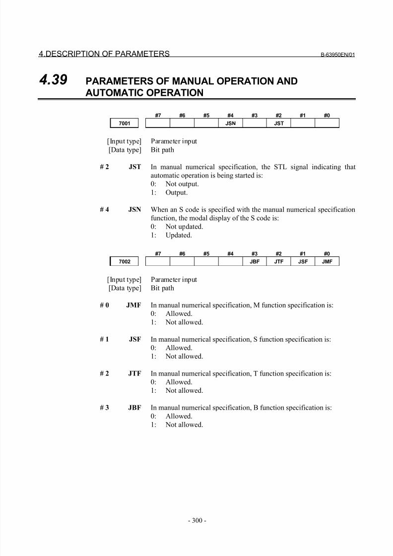
8/21/2019 30i Parameter Manual
http://slidepdf.com/reader/full/30i-parameter-manual 312/493
4.DESCRIPTION OF PARAMETERS B-63950EN/01
- 300 -
4.39 PARAMETERS OF MANUAL OPERATION AND
AUTOMATIC OPERATION
#7 #6 #5 #4 #3 #2 #1 #0
7001 JSN JST
[Input type] Parameter input
[Data type] Bit path
# 2 JST In manual numerical specification, the STL signal indicating that
automatic operation is being started is:
0: Not output.
1: Output.
# 4 JSN When an S code is specified with the manual numerical specification
function, the modal display of the S code is:
0: Not updated.
1: Updated.
#7 #6 #5 #4 #3 #2 #1 #0
7002 JBF JTF JSF JMF
[Input type] Parameter input
[Data type] Bit path
# 0 JMF In manual numerical specification, M function specification is:
0: Allowed.
1: Not allowed.
# 1 JSF In manual numerical specification, S function specification is:
0: Allowed.
1: Not allowed.
# 2 JTF In manual numerical specification, T function specification is:
0: Allowed.
1: Not allowed.
# 3 JBF In manual numerical specification, B function specification is:
0: Allowed.
1: Not allowed.
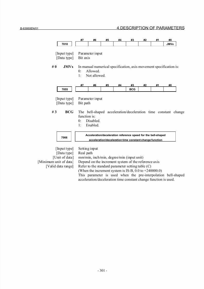
8/21/2019 30i Parameter Manual
http://slidepdf.com/reader/full/30i-parameter-manual 313/493
B-63950EN/01 4.DESCRIPTION OF PARAMETERS
- 301 -
#7 #6 #5 #4 #3 #2 #1 #0
7010 JMVx
[Input type] Parameter input
[Data type] Bit axis
# 0 JMVx In manual numerical specification, axis movement specification is:
0: Allowed.
1: Not allowed.
#7 #6 #5 #4 #3 #2 #1 #0
7055 BCG
[Input type] Parameter input
[Data type] Bit path
# 3 BCG The bell-shaped acceleration/deceleration time constant change
function is:
0: Disabled.
1: Enabled.
7066Acceleration/deceleration reference speed for the bell-shaped
acceleration/deceleration time constant change function
[Input type] Setting input
[Data type] Real path[Unit of data] mm/min, inch/min, degree/min (input unit)
[Minimum unit of data] Depend on the increment system of the reference axis
[Valid data range] Refer to the standard parameter setting table (C)
(When the increment system is IS-B, 0.0 to +240000.0)
This parameter is used when the pre-interpolation bell-shaped
acceleration/deceleration time constant change function is used.
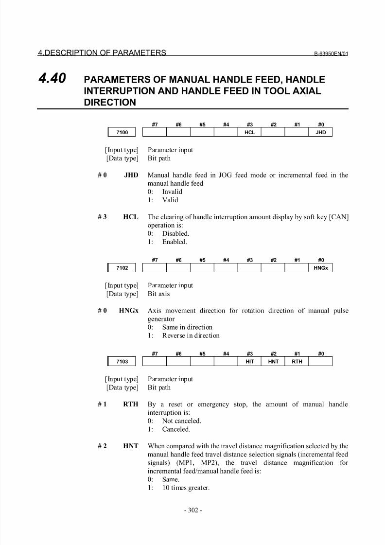
8/21/2019 30i Parameter Manual
http://slidepdf.com/reader/full/30i-parameter-manual 314/493
4.DESCRIPTION OF PARAMETERS B-63950EN/01
- 302 -
4.40 PARAMETERS OF MANUAL HANDLE FEED, HANDLE
INTERRUPTION AND HANDLE FEED IN TOOL AXIALDIRECTION
#7 #6 #5 #4 #3 #2 #1 #0
7100 HCL JHD
[Input type] Parameter input
[Data type] Bit path
# 0 JHD Manual handle feed in JOG feed mode or incremental feed in the
manual handle feed
0: Invalid1: Valid
# 3 HCL The clearing of handle interruption amount display by soft key [CAN]
operation is:
0: Disabled.
1: Enabled.
#7 #6 #5 #4 #3 #2 #1 #0
7102 HNGx
[Input type] Parameter input[Data type] Bit axis
# 0 HNGx Axis movement direction for rotation direction of manual pulse
generator
0: Same in direction
1: Reverse in direction
#7 #6 #5 #4 #3 #2 #1 #0
7103 HIT HNT RTH
[Input type] Parameter input[Data type] Bit path
# 1 RTH By a reset or emergency stop, the amount of manual handle
interruption is:
0: Not canceled.
1: Canceled.
# 2 HNT When compared with the travel distance magnification selected by the
manual handle feed travel distance selection signals (incremental feed
signals) (MP1, MP2), the travel distance magnification for
incremental feed/manual handle feed is:
0: Same.1: 10 times greater.
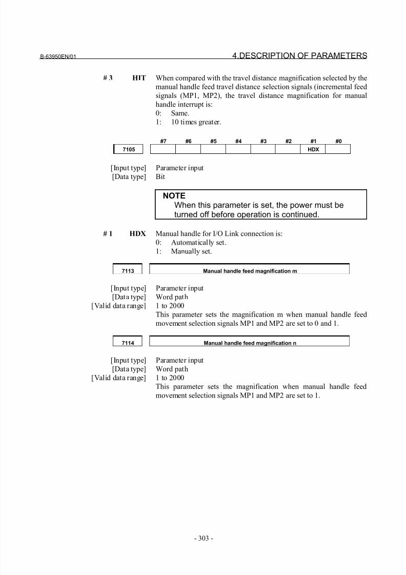
8/21/2019 30i Parameter Manual
http://slidepdf.com/reader/full/30i-parameter-manual 315/493
B-63950EN/01 4.DESCRIPTION OF PARAMETERS
- 303 -
# 3 HIT When compared with the travel distance magnification selected by the
manual handle feed travel distance selection signals (incremental feed
signals (MP1, MP2), the travel distance magnification for manual
handle interrupt is:
0: Same.
1: 10 times greater.
#7 #6 #5 #4 #3 #2 #1 #0
7105 HDX
[Input type] Parameter input
[Data type] Bit
NOTEWhen this parameter is set, the power must beturned off before operation is continued.
# 1 HDX Manual handle for I/O Link connection is:
0: Automatically set.
1: Manually set.
7113 Manual handle feed magnification m
[Input type] Parameter input
[Data type] Word path
[Valid data range] 1 to 2000
This parameter sets the magnification m when manual handle feed
movement selection signals MP1 and MP2 are set to 0 and 1.
7114 Manual handle feed magnification n
[Input type] Parameter input
[Data type] Word path
[Valid data range] 1 to 2000
This parameter sets the magnification when manual handle feed
movement selection signals MP1 and MP2 are set to 1.
8/21/2019 30i Parameter Manual
http://slidepdf.com/reader/full/30i-parameter-manual 316/493
4.DESCRIPTION OF PARAMETERS B-63950EN/01
- 304 -
7117Allowable number of pulses that can be accumulated during manual handle
feed
[Input type] Parameter input
[Data type] 2-word path
[Unit of data] Pulse
[Valid data range] 0 to 999999999
This parameter sets the number of pulses from the manual pulse
generator that exceed the rapid traverse rate and can be accumulated
without being discarded if manual handle feed faster than the rapid
traverse rate is specified.
0:
The feedrate is clamped to the rapid traverse rate. Those handle
pulses that exceed the rapid traverse rate are ignored. (The scalereading of the manual pulse generator may not match the travel
distance.)
Other than 0:
The feedrate is clamped to the rapid traverse rate. However,
those handle pulses that exceed the rapid traverse rate are not
ignored. In connection with the manual handle feed travel
distance selection signals MP1 and MP2 <G019#4, #5>, the
incremental feed amount is determined as described below.
(Even if the rotation of the manual pulse generator is stopped,
the tool stops after moving by the number of pulses accumulatedin the CNC.)
Let m be the magnification based on MP1 and MP2 <G019#4, #5>,
and let n be the value set in parameter No. 7117. Then, the manual
handle increment feed amount is:
When n < m:
Clamped to the value set in parameter No. 7117.
When n ≥ m:
Clamped to a multiple of the selected magnification.
8/21/2019 30i Parameter Manual
http://slidepdf.com/reader/full/30i-parameter-manual 317/493
B-63950EN/01 4.DESCRIPTION OF PARAMETERS
- 305 -
4.41 PARAMETERS OF REFERENCE POSITION WITH
MECHANICAL STOPPER
7181First withdrawal distance in reference position setting with mechanical
stopper
7182Second withdrawal distance in butt-type reference position setting with
mechanical stopper
[Input type] Parameter input
[Data type] Real axis
[Unit of data] mm, inch, degree (machine unit)
[Minimum unit of data] Depend on the increment system of the applied axis[Valid data range] 9 digit of minimum unit of data (refer to standard parameter setting
table (A) )
(When the increment system is IS-B, -999999.999 to +999999.999)
This parameter sets a distance an axis in each cycle operation, along
which withdrawal is performed after the mechanical stopper is hit
(distance from the mechanical stopper to the withdrawal point).
NOTESet the same direction as that set in bit 5 (ZMIx) of parameter No. 1006. Cycle operation cannot be
started if the opposite direction is set.
7183 First butting feedrate in reference position setting with mechanical stopper
7184Second butting feedrate in reference position setting with mechanical
stopper
7185Withdrawal feedrate (common to the first and second butting operations) in
reference position setting with mechanical stopper
[Input type] Parameter input
[Data type] Real axis
[Unit of data] mm/min, inch/min, degree/min (machine unit)
[Minimum unit of data] Depend on the increment system of the applied axis
[Valid data range] Refer to the standard parameter setting table (C)
(When the increment system is IS-B, 0.0 to +240000.0)
This parameter sets a feedrate used to butt against the stopper along
an axis in each cycle.
8/21/2019 30i Parameter Manual
http://slidepdf.com/reader/full/30i-parameter-manual 318/493
4.DESCRIPTION OF PARAMETERS B-63950EN/01
- 306 -
7186Torque limit value in butt-type reference position setting with mechanical
stopper
[Input type] Parameter input
[Data type] Byte axis
[Unit of data] %
[Valid data range] 0 to 100
This parameter sets a torque limit value.
NOTEWhen 0 is set in this parameter, 100% is assumed.
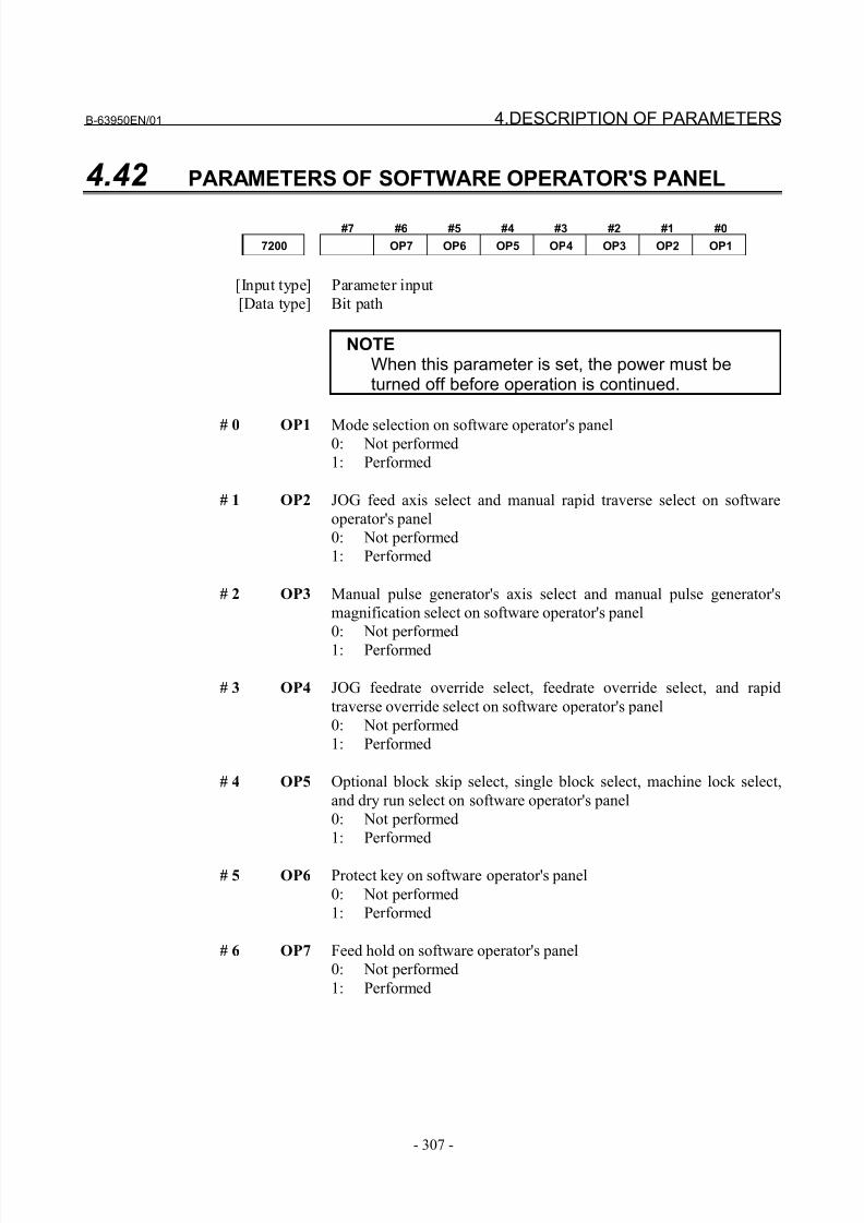
8/21/2019 30i Parameter Manual
http://slidepdf.com/reader/full/30i-parameter-manual 319/493
B-63950EN/01 4.DESCRIPTION OF PARAMETERS
- 307 -
4.42 PARAMETERS OF SOFTWARE OPERATOR'S PANEL
#7 #6 #5 #4 #3 #2 #1 #0
7200 OP7 OP6 OP5 OP4 OP3 OP2 OP1
[Input type] Parameter input
[Data type] Bit path
NOTEWhen this parameter is set, the power must beturned off before operation is continued.
# 0 OP1 Mode selection on software operator's panel0: Not performed
1: Performed
# 1 OP2 JOG feed axis select and manual rapid traverse select on software
operator's panel
0: Not performed
1: Performed
# 2 OP3 Manual pulse generator's axis select and manual pulse generator's
magnification select on software operator's panel
0: Not performed
1: Performed
# 3 OP4 JOG feedrate override select, feedrate override select, and rapid
traverse override select on software operator's panel
0: Not performed
1: Performed
# 4 OP5 Optional block skip select, single block select, machine lock select,
and dry run select on software operator's panel
0: Not performed
1: Performed
# 5 OP6 Protect key on software operator's panel
0: Not performed
1: Performed
# 6 OP7 Feed hold on software operator's panel
0: Not performed
1: Performed

8/21/2019 30i Parameter Manual
http://slidepdf.com/reader/full/30i-parameter-manual 320/493
4.DESCRIPTION OF PARAMETERS B-63950EN/01
- 308 -
#7 #6 #5 #4 #3 #2 #1 #0
7201 JPC
[Input type] Parameter input
[Data type] Bit path
# 0 JPC For the name of a general-purpose switch function on the software
operator's panel, the use of full-size characters is:
0: Not allowed.
1: Allowed.
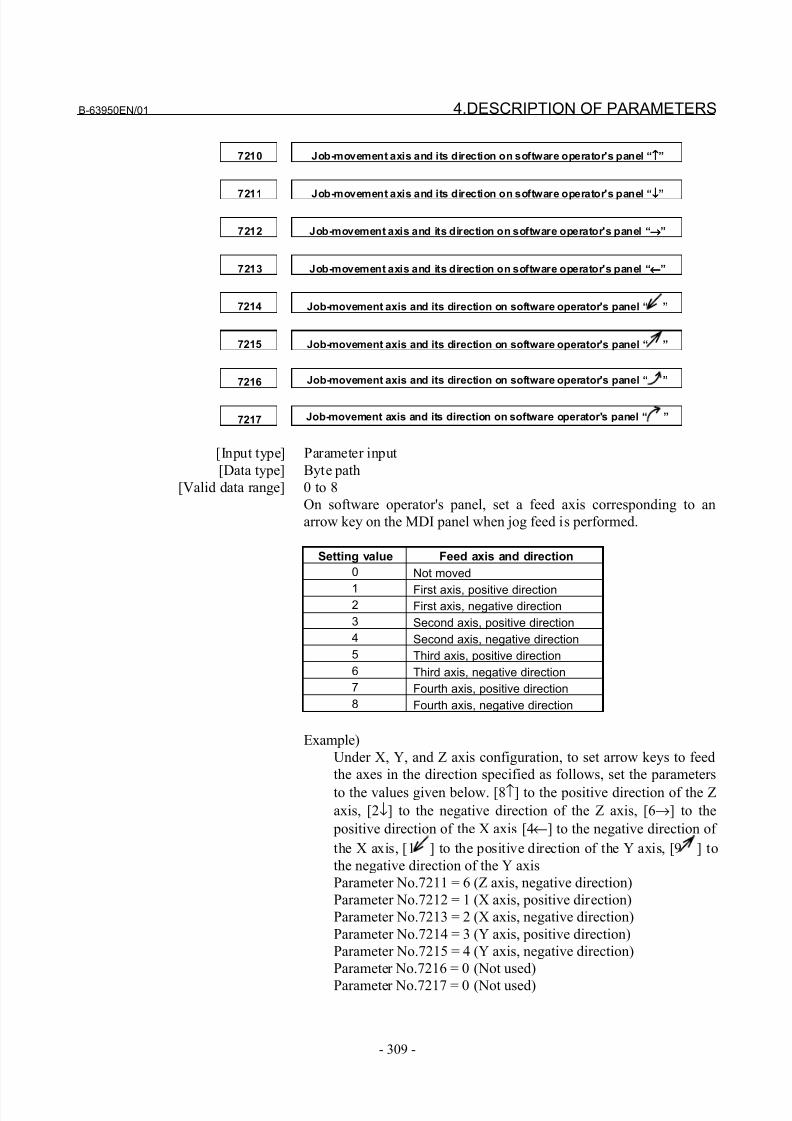
8/21/2019 30i Parameter Manual
http://slidepdf.com/reader/full/30i-parameter-manual 321/493
B-63950EN/01 4.DESCRIPTION OF PARAMETERS
- 309 -
7210 Job-movement axis and its direction on software operator's panel “↑↑↑↑”
7211 Job-movement axis and its direction on software operator's panel “↓↓↓↓”
7212 Job-movement axis and its direction on software operator's panel “→→→→”
7213 Job-movement axis and its direction on software operator's panel “←←←←”
7214 Job-movement axis and its direction on software operator's panel “ ”
7215 Job-movement axis and its direction on software operator's panel “ ”
7216 Job-movement axis and its direction on software operator's panel “ ”
7217 Job-movement axis and its direction on software operator's panel “ ”
[Input type] Parameter input
[Data type] Byte path
[Valid data range] 0 to 8
On software operator's panel, set a feed axis corresponding to an
arrow key on the MDI panel when jog feed is performed.
Setting value Feed axis and direction
0 Not moved
1 First axis, positive direction2 First axis, negative direction
3 Second axis, positive direction
4 Second axis, negative direction
5 Third axis, positive direction
6 Third axis, negative direction
7 Fourth axis, positive direction
8 Fourth axis, negative direction
Example)
Under X, Y, and Z axis configuration, to set arrow keys to feed
the axes in the direction specified as follows, set the parameters
to the values given below. [8↑] to the positive direction of the Z
axis, [2↓] to the negative direction of the Z axis, [6→] to the
positive direction of the X axis [4←] to the negative direction of
the X axis, [1 ] to the positive direction of the Y axis, [9 ] to
the negative direction of the Y axis
Parameter No.7211 = 6 (Z axis, negative direction)
Parameter No.7212 = 1 (X axis, positive direction)
Parameter No.7213 = 2 (X axis, negative direction)
Parameter No.7214 = 3 (Y axis, positive direction)
Parameter No.7215 = 4 (Y axis, negative direction)
Parameter No.7216 = 0 (Not used)
Parameter No.7217 = 0 (Not used)
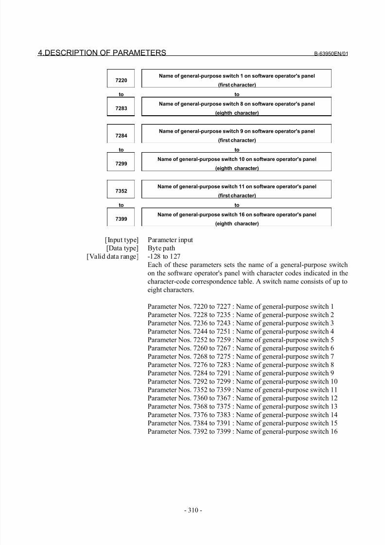
8/21/2019 30i Parameter Manual
http://slidepdf.com/reader/full/30i-parameter-manual 322/493
4.DESCRIPTION OF PARAMETERS B-63950EN/01
- 310 -
7220Name of general-purpose switch 1 on software operator's panel
(first character)
to to
7283Name of general-purpose switch 8 on software operator's panel
(eighth character)
7284Name of general-purpose switch 9 on software operator's panel
(first character)
to to
7299Name of general-purpose switch 10 on software operator's panel
(eighth character)
7352
Name of general-purpose switch 11 on software operator's panel
(first character)
to to
7399Name of general-purpose switch 16 on software operator's panel
(eighth character)
[Input type] Parameter input
[Data type] Byte path
[Valid data range] -128 to 127
Each of these parameters sets the name of a general-purpose switch
on the software operator's panel with character codes indicated in the
character-code correspondence table. A switch name consists of up to
eight characters.
Parameter Nos. 7220 to 7227 : Name of general-purpose switch 1
Parameter Nos. 7228 to 7235 : Name of general-purpose switch 2
Parameter Nos. 7236 to 7243 : Name of general-purpose switch 3
Parameter Nos. 7244 to 7251 : Name of general-purpose switch 4
Parameter Nos. 7252 to 7259 : Name of general-purpose switch 5
Parameter Nos. 7260 to 7267 : Name of general-purpose switch 6
Parameter Nos. 7268 to 7275 : Name of general-purpose switch 7
Parameter Nos. 7276 to 7283 : Name of general-purpose switch 8
Parameter Nos. 7284 to 7291 : Name of general-purpose switch 9
Parameter Nos. 7292 to 7299 : Name of general-purpose switch 10Parameter Nos. 7352 to 7359 : Name of general-purpose switch 11
Parameter Nos. 7360 to 7367 : Name of general-purpose switch 12
Parameter Nos. 7368 to 7375 : Name of general-purpose switch 13
Parameter Nos. 7376 to 7383 : Name of general-purpose switch 14
Parameter Nos. 7384 to 7391 : Name of general-purpose switch 15
Parameter Nos. 7392 to 7399 : Name of general-purpose switch 16
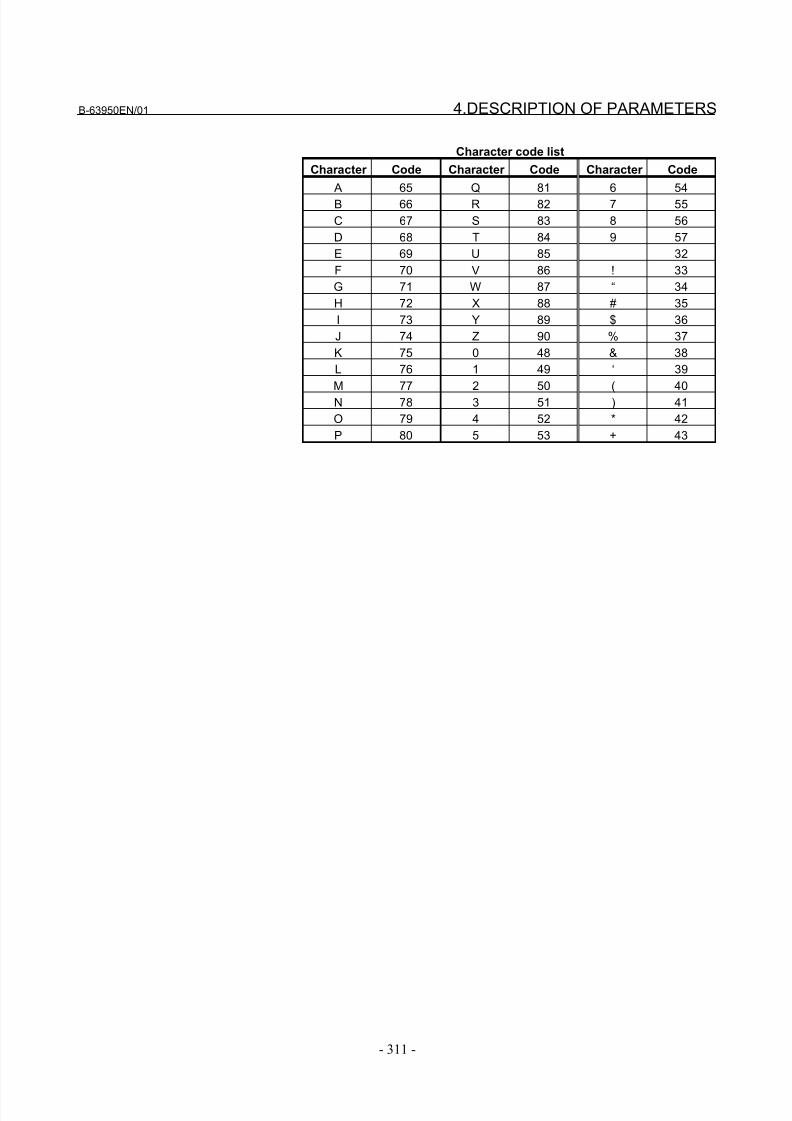
8/21/2019 30i Parameter Manual
http://slidepdf.com/reader/full/30i-parameter-manual 323/493
B-63950EN/01 4.DESCRIPTION OF PARAMETERS
- 311 -
Character code list
Character Code Character Code Character Code
A 65 Q 81 6 54
B 66 R 82 7 55
C 67 S 83 8 56
D 68 T 84 9 57
E 69 U 85 32
F 70 V 86 ! 33
G 71 W 87 “ 34
H 72 X 88 # 35
I 73 Y 89 $ 36
J 74 Z 90 % 37
K 75 0 48 & 38
L 76 1 49 ‘ 39
M 77 2 50 ( 40
N 78 3 51 ) 41
O 79 4 52 * 42
P 80 5 53 + 43
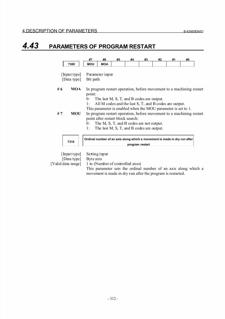
8/21/2019 30i Parameter Manual
http://slidepdf.com/reader/full/30i-parameter-manual 324/493
4.DESCRIPTION OF PARAMETERS B-63950EN/01
- 312 -
4.43 PARAMETERS OF PROGRAM RESTART
#7 #6 #5 #4 #3 #2 #1 #0
7300 MOU MOA
[Input type] Parameter input
[Data type] Bit path
# 6 MOA In program restart operation, before movement to a machining restart
point:
0: The last M, S, T, and B codes are output.
1: All M codes and the last S, T, and B codes are output.
This parameter is enabled when the MOU parameter is set to 1.
# 7 MOU In program restart operation, before movement to a machining restart
point after restart block search:
0: The M, S, T, and B codes are not output.
1: The last M, S, T, and B codes are output.
7310Ordinal number of an axis along which a movement is made in dry run after
program restart
[Input type] Setting input
[Data type] Byte axis
[Valid data range] 1 to (Number of controlled axes)
This parameter sets the ordinal number of an axis along which amovement is made in dry run after the program is restarted.
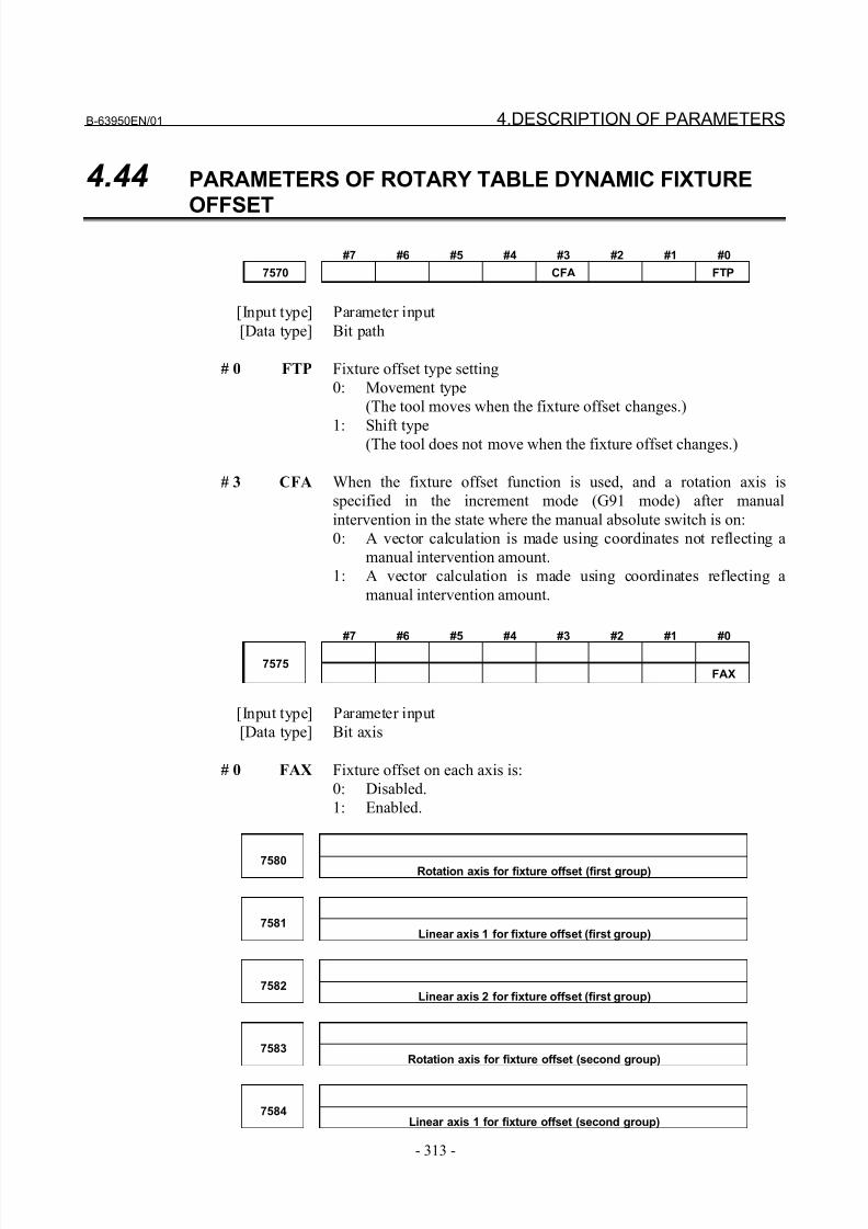
8/21/2019 30i Parameter Manual
http://slidepdf.com/reader/full/30i-parameter-manual 325/493
B-63950EN/01 4.DESCRIPTION OF PARAMETERS
- 313 -
4.44 PARAMETERS OF ROTARY TABLE DYNAMIC FIXTURE
OFFSET
#7 #6 #5 #4 #3 #2 #1 #0
7570 CFA FTP
[Input type] Parameter input
[Data type] Bit path
# 0 FTP Fixture offset type setting
0: Movement type
(The tool moves when the fixture offset changes.)
1: Shift type(The tool does not move when the fixture offset changes.)
# 3 CFA When the fixture offset function is used, and a rotation axis is
specified in the increment mode (G91 mode) after manual
intervention in the state where the manual absolute switch is on:
0: A vector calculation is made using coordinates not reflecting a
manual intervention amount.
1: A vector calculation is made using coordinates reflecting a
manual intervention amount.
#7 #6 #5 #4 #3 #2 #1 #0
7575FAX
[Input type] Parameter input
[Data type] Bit axis
# 0 FAX Fixture offset on each axis is:
0: Disabled.
1: Enabled.
7580 Rotation axis for fixture offset (first group)
7581Linear axis 1 for fixture offset (first group)
7582Linear axis 2 for fixture offset (first group)
7583Rotation axis for fixture offset (second group)
7584Linear axis 1 for fixture offset (second group)
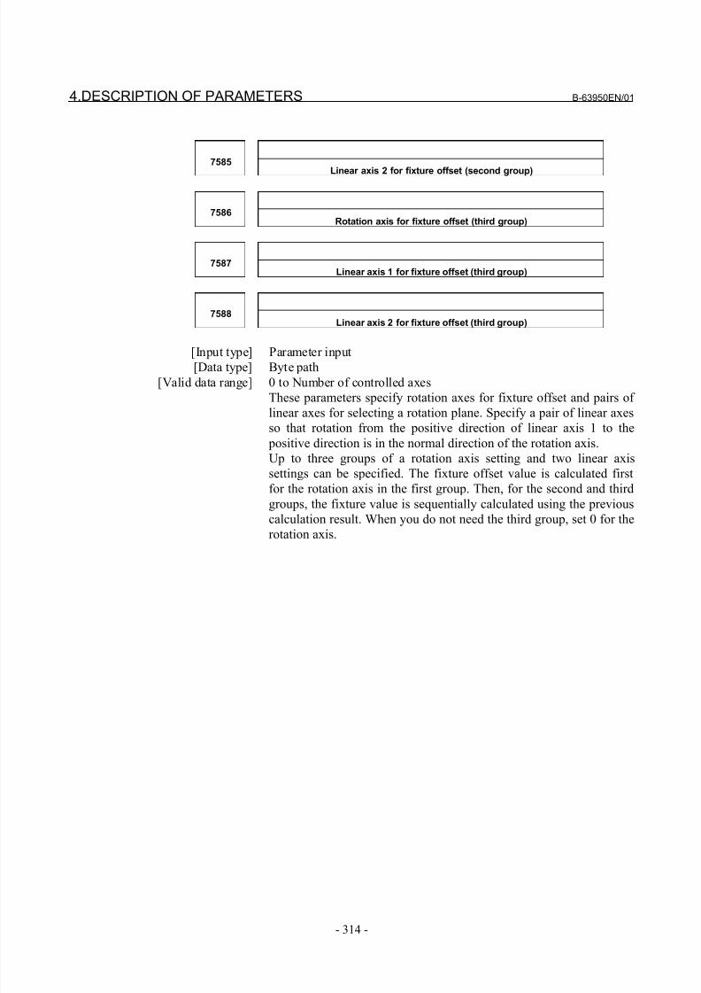
8/21/2019 30i Parameter Manual
http://slidepdf.com/reader/full/30i-parameter-manual 326/493
4.DESCRIPTION OF PARAMETERS B-63950EN/01
- 314 -
7585
Linear axis 2 for fixture offset (second group)
7586Rotation axis for fixture offset (third group)
7587Linear axis 1 for fixture offset (third group)
7588Linear axis 2 for fixture offset (third group)
[Input type] Parameter input[Data type] Byte path
[Valid data range] 0 to Number of controlled axes
These parameters specify rotation axes for fixture offset and pairs of
linear axes for selecting a rotation plane. Specify a pair of linear axes
so that rotation from the positive direction of linear axis 1 to the
positive direction is in the normal direction of the rotation axis.
Up to three groups of a rotation axis setting and two linear axis
settings can be specified. The fixture offset value is calculated first
for the rotation axis in the first group. Then, for the second and third
groups, the fixture value is sequentially calculated using the previous
calculation result. When you do not need the third group, set 0 for therotation axis.
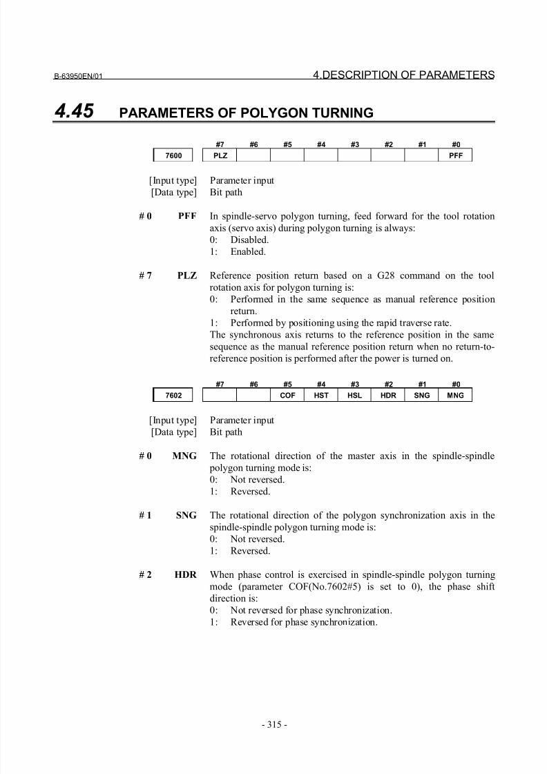
8/21/2019 30i Parameter Manual
http://slidepdf.com/reader/full/30i-parameter-manual 327/493
B-63950EN/01 4.DESCRIPTION OF PARAMETERS
- 315 -
4.45 PARAMETERS OF POLYGON TURNING
#7 #6 #5 #4 #3 #2 #1 #0
7600 PLZ PFF
[Input type] Parameter input
[Data type] Bit path
# 0 PFF In spindle-servo polygon turning, feed forward for the tool rotation
axis (servo axis) during polygon turning is always:
0: Disabled.
1: Enabled.
# 7 PLZ Reference position return based on a G28 command on the tool
rotation axis for polygon turning is:
0: Performed in the same sequence as manual reference position
return.
1: Performed by positioning using the rapid traverse rate.
The synchronous axis returns to the reference position in the same
sequence as the manual reference position return when no return-to-
reference position is performed after the power is turned on.
#7 #6 #5 #4 #3 #2 #1 #0
7602 COF HST HSL HDR SNG MNG
[Input type] Parameter input
[Data type] Bit path
# 0 MNG The rotational direction of the master axis in the spindle-spindle
polygon turning mode is:
0: Not reversed.
1: Reversed.
# 1 SNG The rotational direction of the polygon synchronization axis in the
spindle-spindle polygon turning mode is:
0: Not reversed.1: Reversed.
# 2 HDR When phase control is exercised in spindle-spindle polygon turning
mode (parameter COF(No.7602#5) is set to 0), the phase shift
direction is:
0: Not reversed for phase synchronization.
1: Reversed for phase synchronization.
8/21/2019 30i Parameter Manual
http://slidepdf.com/reader/full/30i-parameter-manual 328/493
4.DESCRIPTION OF PARAMETERS B-63950EN/01
- 316 -
NOTEThe rotation directions and phase shift directions of
the master axis and polygon synchronization axis inthe spindle-spindle polygon turning mode can bereversed with a programmed command. MNG,SNG, and HDR are used to reverse an actualdirection relative to the programmed command.
# 3 HSL When phase control is exercised in spindle-spindle polygon turning
mode (parameter COF(No.7602#5) is set to 0), this parameter selects
the spindle that is subject to a phase shift operation for phase
synchronization:
0: The polygon synchronization axis is selected.
1: The master axis is selected.
NOTE1 Select an axis to which a phase shift command is
applied.2 Spindle operation for phase synchronization is
performed with both spindles.
# 4 HST When phase control is applied in spindle-spindle polygon turning
mode (parameter COF(No.7602#5) is set to 0), and spindle-spindle
polygon turning mode is specified:
0: Spindle-spindle polygon turning mode is entered with the currentspindle speed maintained.
1: Spindle-spindle polygon turning mode is entered after the
spindle is stopped.
NOTEThis parameter can be used, for example, whensingle-rotation signal detection cannot beguaranteed at an arbitrary feedrate because aseparate detector is installed to detect the spindlesingle-rotation signal, as when a built-in spindle is
used. (When bit 7 of parameter No.4016 for theserial spindle is set to 1, together with thisparameter, a single-rotation signal detectionposition in spindle-spindle polygon turning mode isguaranteed.)
# 5 COF In spindle-spindle polygon turning mode, phase control is:
0: Enabled.
1: Disabled.
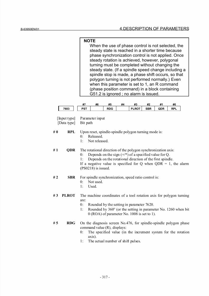
8/21/2019 30i Parameter Manual
http://slidepdf.com/reader/full/30i-parameter-manual 329/493
B-63950EN/01 4.DESCRIPTION OF PARAMETERS
- 317 -
NOTEWhen the use of phase control is not selected, the
steady state is reached in a shorter time becausephase synchronization control is not applied. Oncesteady rotation is achieved, however, polygonalturning must be completed without changing thesteady state. (If a spindle speed change including aspindle stop is made, a phase shift occurs, so thatpolygon turning is not performed normally.) Evenwhen this parameter is set to 1, an R command(phase position command) in a block containingG51.2 is ignored ; no alarm is issued.
#7 #6 #5 #4 #3 #2 #1 #0
7603 PST RDG PLROT SBR QDR RPL
[Input type] Parameter input
[Data type] Bit path
# 0 RPL Upon reset, spindle-spindle polygon turning mode is:
0: Released.
1: Not released.
# 1 QDR The rotational direction of the polygon synchronization axis:
0: Depends on the sign (+/*) of a specified value for Q.1: Depends on the rotational direction of the first spindle.
If a negative value is specified for Q when QDR = 1, the alarm
(PS0218) is issued.
# 2 SBR For spindle synchronization, speed ratio control is:
0: Not used.
1: Used.
# 3 PLROT The machine coordinates of a tool rotation axis for polygon turning
are:
0: Rounded by the setting in parameter 7620.
1: Rounded by 360° (or the setting in parameter No. 1260 when bit
0 (ROA) of parameter No. 1008 is set to 1).
# 5 RDG On the diagnosis screen No.476, for spindle-spindle polygon phase
command value (R), displays:
0: The specified value (in the increment system for the rotation
axis).
1: The actual number of shift pulses.
8/21/2019 30i Parameter Manual
http://slidepdf.com/reader/full/30i-parameter-manual 330/493
4.DESCRIPTION OF PARAMETERS B-63950EN/01
- 318 -
NOTE A phase command is specified in address R, in
units of degrees. For control, the actual shiftamount is converted to a number of pulsesaccording to the conversion formula: 360 degrees =4096 pulses. This parameter switches the displayof a specified value to that of a converted value.
# 7 PST The polygon spindle stop signal *PLSST <Gn038.0>is:
0: Not used.
1: Used.
7610 Control axis number of tool rotation axis for polygon turning
NOTEWhen this parameter is set, the power must beturned off before operation is continued.
[Input type] Parameter input
[Data type] Byte path
[Valid data range] 1 to number of controlled axes
This parameter sets the control axis number of a rotation tool axis
used for polygon turning.
However, when a G51.2 command is executed by setting 0 in this
parameter, operation stops with the alarm (PS0314).
7620 Movement of tool rotation axis per revolution for polygon turning
NOTEWhen this parameter is set, the power must beturned off before operation is continued.
[Input type] Parameter input
[Data type] Real path
[Unit of data] Degree
[Minimum unit of data] Depend on the increment system of the applied axis[Valid data range] 0 or positive 9 digit of minimum unit of data (refer to the standard
parameter setting table (B) )
(When the increment system is IS-B, 0.0 to +999999.999)
This parameter sets the movement of a tool rotation axis per
revolution.
8/21/2019 30i Parameter Manual
http://slidepdf.com/reader/full/30i-parameter-manual 331/493
B-63950EN/01 4.DESCRIPTION OF PARAMETERS
- 319 -
7621 Maximum allowable speed for the tool rotation axis for polygon turning
NOTEWhen this parameter is set, the power must beturned off before operation is continued.
[Input type] Parameter input
[Data type] 2-word path
[Unit of data] min-1
[Valid data range] 0 or positive 9 digit of minimum unit of data (refer to the standard
parameter setting table (B) )
(When the increment system is IS-B, 0.0 to +999999.999)
This parameter sets the maximum allowable speed of the tool rotation
axis.
NOTEIf the speed of the tool rotation axis exceeds the setmaximum allowable speed during polygon turning,the synchronization between the spindle and toolrotation axis is lost, and operation stops with alarmPS5018.
7631 Allowable spindle speed deviation level in spindle-spindle polygon turning
[Input type] Parameter input[Data type] Word path
[Unit of data] min-1
[Valid data range] 0 to 99999999
This parameter sets the allowable level of deviation between the
actual speed and specified speed of each spindle in spindle-spindle
polygon turning. The value set with this parameter is used for both the
master axis and polygon synchronization axis.
When 0 is set in this parameter, the specification of 8 [min-1
] is
assumed.
7632 Steady state confirmation time duration in spindle polygon turning
[Input type] Parameter input
[Data type] Word path
[Unit of data] msec
[Valid data range] 0 to 32767
This parameter sets the duration required to confirm that both
spindles have reached their specified speeds in spindle-spindle
polygon turning.
If the state where the speed of each spindle is within the range set
with parameter No.7631, and has lasted at least for the duration
specified with parameter No.7632, the spindle polygon speed arrival
signal PSAR <Fn063.2> is set to 1.When 0 is set in this parameter, the specification of 64 [msec] is
assumed.
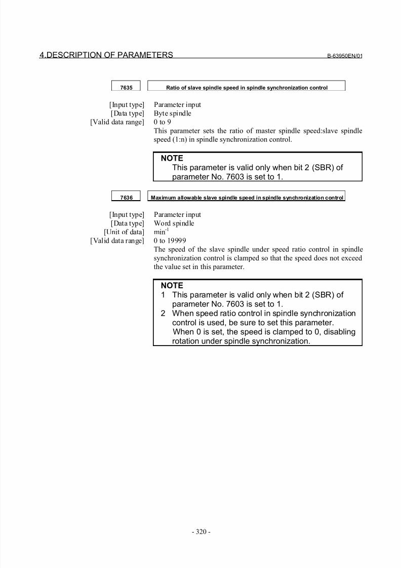
8/21/2019 30i Parameter Manual
http://slidepdf.com/reader/full/30i-parameter-manual 332/493
4.DESCRIPTION OF PARAMETERS B-63950EN/01
- 320 -
7635 Ratio of slave spindle speed in spindle synchronization control
[Input type] Parameter input
[Data type] Byte spindle
[Valid data range] 0 to 9
This parameter sets the ratio of master spindle speed:slave spindle
speed (1:n) in spindle synchronization control.
NOTEThis parameter is valid only when bit 2 (SBR) of parameter No. 7603 is set to 1.
7636 Maximum allowable slave spindle speed in spindle synchronization control
[Input type] Parameter input
[Data type] Word spindle
[Unit of data] min-1
[Valid data range] 0 to 19999
The speed of the slave spindle under speed ratio control in spindle
synchronization control is clamped so that the speed does not exceed
the value set in this parameter.
NOTE
1 This parameter is valid only when bit 2 (SBR) of parameter No. 7603 is set to 1.2 When speed ratio control in spindle synchronization
control is used, be sure to set this parameter. When 0 is set, the speed is clamped to 0, disabling
rotation under spindle synchronization.
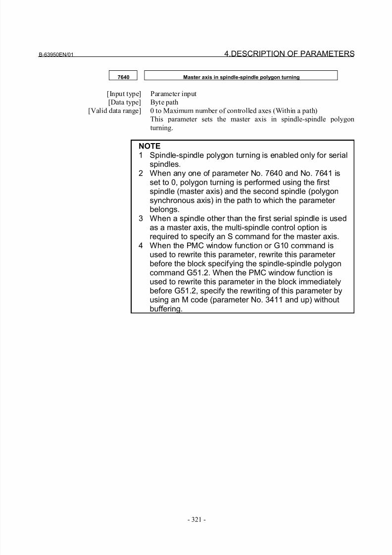
8/21/2019 30i Parameter Manual
http://slidepdf.com/reader/full/30i-parameter-manual 333/493
B-63950EN/01 4.DESCRIPTION OF PARAMETERS
- 321 -
7640 Master axis in spindle-spindle polygon turning
[Input type] Parameter input[Data type] Byte path
[Valid data range] 0 to Maximum number of controlled axes (Within a path)
This parameter sets the master axis in spindle-spindle polygon
turning.
NOTE1 Spindle-spindle polygon turning is enabled only for serial
spindles.2 When any one of parameter No. 7640 and No. 7641 is
set to 0, polygon turning is performed using the first
spindle (master axis) and the second spindle (polygonsynchronous axis) in the path to which the parameter belongs.
3 When a spindle other than the first serial spindle is usedas a master axis, the multi-spindle control option isrequired to specify an S command for the master axis.
4 When the PMC window function or G10 command isused to rewrite this parameter, rewrite this parameter before the block specifying the spindle-spindle polygoncommand G51.2. When the PMC window function isused to rewrite this parameter in the block immediately
before G51.2, specify the rewriting of this parameter byusing an M code (parameter No. 3411 and up) withoutbuffering.
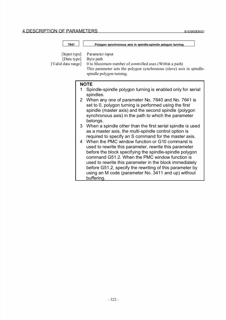
8/21/2019 30i Parameter Manual
http://slidepdf.com/reader/full/30i-parameter-manual 334/493
4.DESCRIPTION OF PARAMETERS B-63950EN/01
- 322 -
7641 Polygon synchronous axis in spindle-spindle polygon turning
[Input type] Parameter input[Data type] Byte path
[Valid data range] 0 to Maximum number of controlled axes (Within a path)
This parameter sets the polygon synchronous (slave) axis in spindle-
spindle polygon turning.
NOTE1 Spindle-spindle polygon turning is enabled only for serial
spindles.2 When any one of parameter No. 7640 and No. 7641 is
set to 0, polygon turning is performed using the first
spindle (master axis) and the second spindle (polygonsynchronous axis) in the path to which the parameter belongs.
3 When a spindle other than the first serial spindle is usedas a master axis, the multi-spindle control option isrequired to specify an S command for the master axis.
4 When the PMC window function or G10 command isused to rewrite this parameter, rewrite this parameter before the block specifying the spindle-spindle polygoncommand G51.2. When the PMC window function isused to rewrite this parameter in the block immediately
before G51.2, specify the rewriting of this parameter byusing an M code (parameter No. 3411 and up) withoutbuffering.
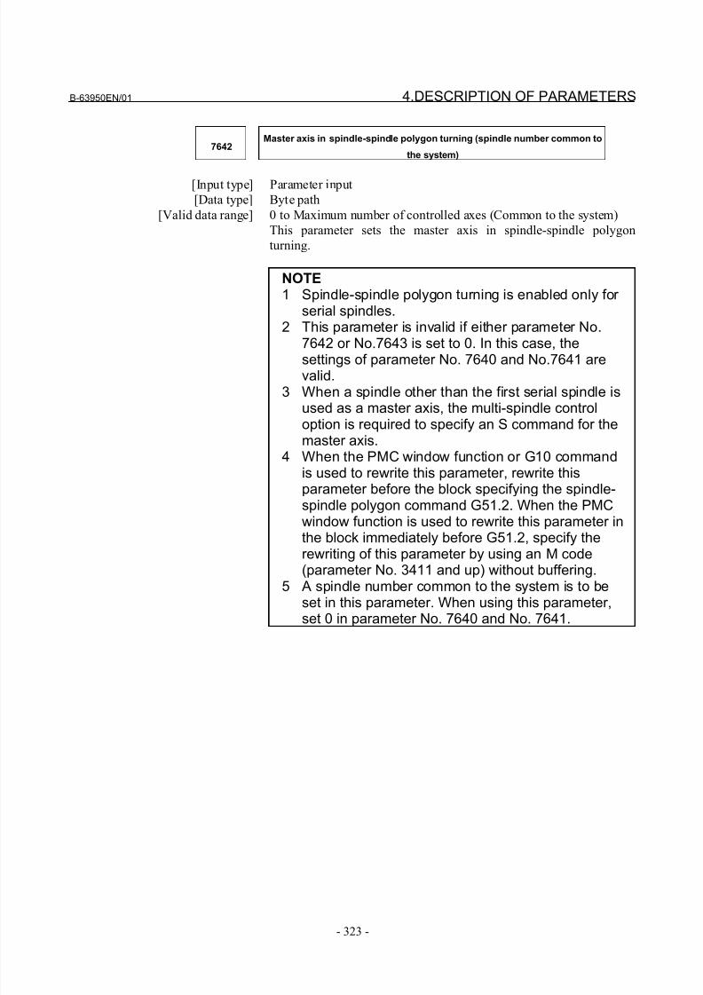
8/21/2019 30i Parameter Manual
http://slidepdf.com/reader/full/30i-parameter-manual 335/493
B-63950EN/01 4.DESCRIPTION OF PARAMETERS
- 323 -
7642Master axis in spindle-spindle polygon turning (spindle number common to
the system)
[Input type] Parameter input
[Data type] Byte path
[Valid data range] 0 to Maximum number of controlled axes (Common to the system)
This parameter sets the master axis in spindle-spindle polygon
turning.
NOTE1 Spindle-spindle polygon turning is enabled only for
serial spindles.2 This parameter is invalid if either parameter No.
7642 or No.7643 is set to 0. In this case, thesettings of parameter No. 7640 and No.7641 arevalid.
3 When a spindle other than the first serial spindle isused as a master axis, the multi-spindle controloption is required to specify an S command for themaster axis.
4 When the PMC window function or G10 commandis used to rewrite this parameter, rewrite thisparameter before the block specifying the spindle-spindle polygon command G51.2. When the PMC
window function is used to rewrite this parameter inthe block immediately before G51.2, specify therewriting of this parameter by using an M code(parameter No. 3411 and up) without buffering.
5 A spindle number common to the system is to beset in this parameter. When using this parameter,set 0 in parameter No. 7640 and No. 7641.
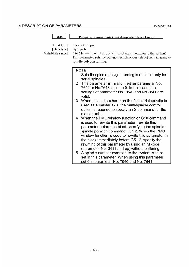
8/21/2019 30i Parameter Manual
http://slidepdf.com/reader/full/30i-parameter-manual 336/493
4.DESCRIPTION OF PARAMETERS B-63950EN/01
- 324 -
7643 Polygon synchronous axis in spindle-spindle polygon turning
[Input type] Parameter input[Data type] Byte path
[Valid data range] 0 to Maximum number of controlled axes (Common to the system)
This parameter sets the polygon synchronous (slave) axis in spindle-
spindle polygon turning.
NOTE1 Spindle-spindle polygon turning is enabled only for
serial spindles.2 This parameter is invalid if either parameter No.
7642 or No.7643 is set to 0. In this case, the
settings of parameter No. 7640 and No.7641 arevalid.3 When a spindle other than the first serial spindle is
used as a master axis, the multi-spindle controloption is required to specify an S command for themaster axis.
4 When the PMC window function or G10 commandis used to rewrite this parameter, rewrite thisparameter before the block specifying the spindle-spindle polygon command G51.2. When the PMCwindow function is used to rewrite this parameter in
the block immediately before G51.2, specify therewriting of this parameter by using an M code(parameter No. 3411 and up) without buffering.
5 A spindle number common to the system is to beset in this parameter. When using this parameter,set 0 in parameter No. 7640 and No. 7641.
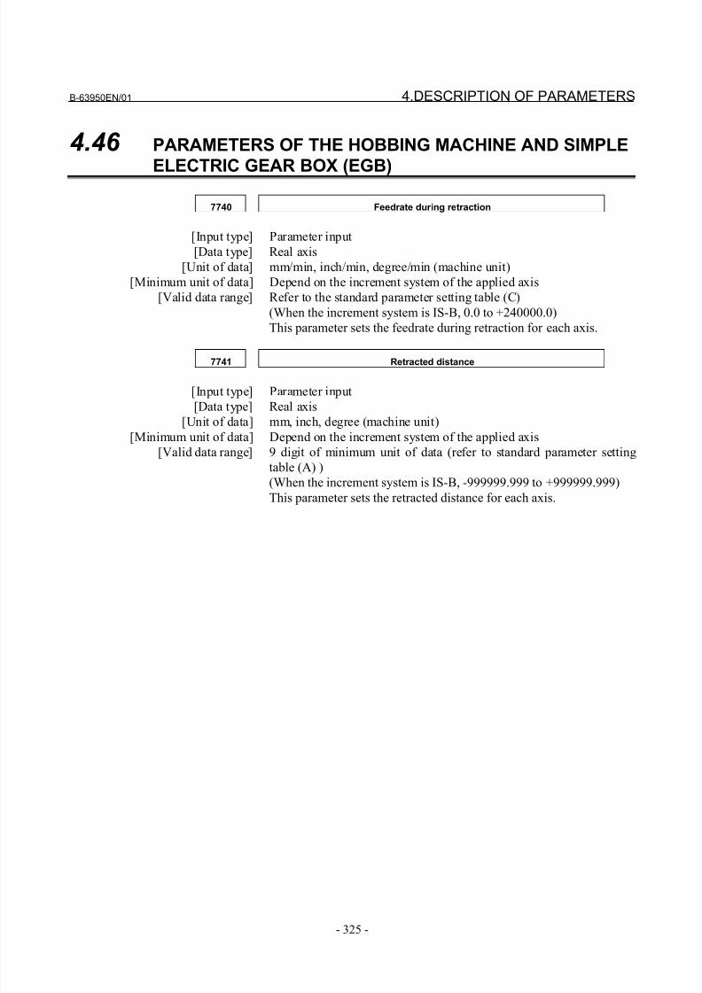
8/21/2019 30i Parameter Manual
http://slidepdf.com/reader/full/30i-parameter-manual 337/493
B-63950EN/01 4.DESCRIPTION OF PARAMETERS
- 325 -
4.46 PARAMETERS OF THE HOBBING MACHINE AND SIMPLE
ELECTRIC GEAR BOX (EGB)
7740 Feedrate during retraction
[Input type] Parameter input
[Data type] Real axis
[Unit of data] mm/min, inch/min, degree/min (machine unit)
[Minimum unit of data] Depend on the increment system of the applied axis
[Valid data range] Refer to the standard parameter setting table (C)
(When the increment system is IS-B, 0.0 to +240000.0)
This parameter sets the feedrate during retraction for each axis.
7741 Retracted distance
[Input type] Parameter input
[Data type] Real axis
[Unit of data] mm, inch, degree (machine unit)
[Minimum unit of data] Depend on the increment system of the applied axis
[Valid data range] 9 digit of minimum unit of data (refer to standard parameter setting
table (A) )
(When the increment system is IS-B, -999999.999 to +999999.999)
This parameter sets the retracted distance for each axis.
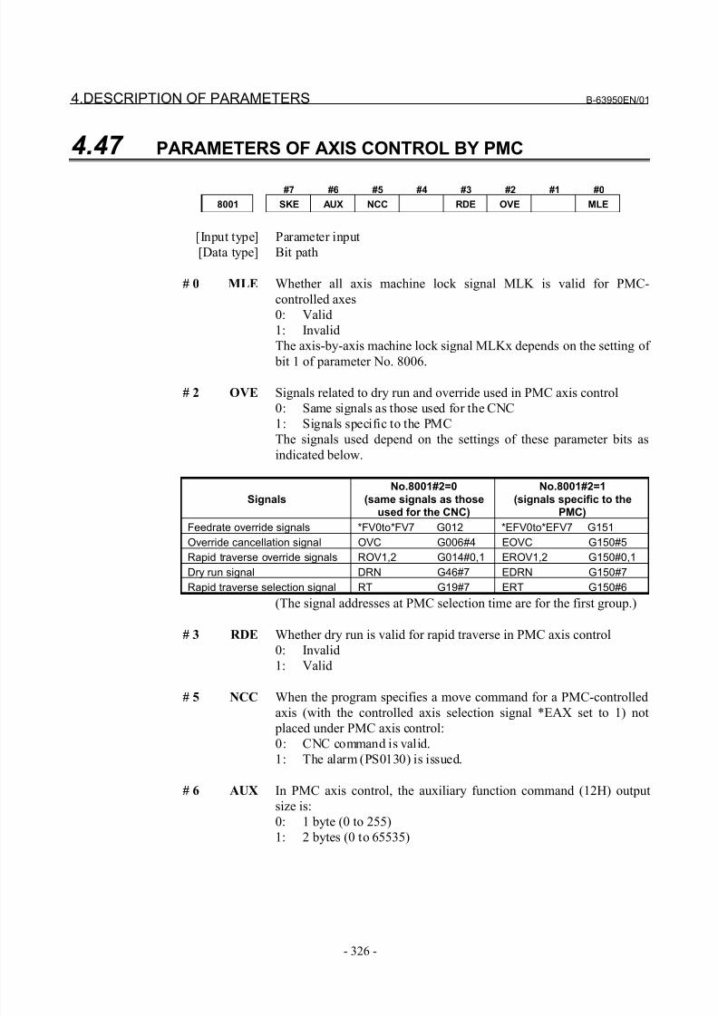
8/21/2019 30i Parameter Manual
http://slidepdf.com/reader/full/30i-parameter-manual 338/493
4.DESCRIPTION OF PARAMETERS B-63950EN/01
- 326 -
4.47 PARAMETERS OF AXIS CONTROL BY PMC
#7 #6 #5 #4 #3 #2 #1 #0
8001 SKE AUX NCC RDE OVE MLE
[Input type] Parameter input
[Data type] Bit path
# 0 MLE Whether all axis machine lock signal MLK is valid for PMC-
controlled axes
0: Valid
1: Invalid
The axis-by-axis machine lock signal MLKx depends on the setting of
bit 1 of parameter No. 8006.
# 2 OVE Signals related to dry run and override used in PMC axis control
0: Same signals as those used for the CNC
1: Signals specific to the PMC
The signals used depend on the settings of these parameter bits as
indicated below.
Signals
No.8001#2=0
(same signals as thoseused for the CNC)
No.8001#2=1
(signals specific to thePMC)
Feedrate override signals *FV0to*FV7 G012 *EFV0to*EFV7 G151
Override cancellation signal OVC G006#4 EOVC G150#5
Rapid traverse override signals ROV1,2 G014#0,1 EROV1,2 G150#0,1
Dry run signal DRN G46#7 EDRN G150#7
Rapid traverse selection signal RT G19#7 ERT G150#6
(The signal addresses at PMC selection time are for the first group.)
# 3 RDE Whether dry run is valid for rapid traverse in PMC axis control
0: Invalid
1: Valid
# 5 NCC When the program specifies a move command for a PMC-controlled
axis (with the controlled axis selection signal *EAX set to 1) not placed under PMC axis control:
0: CNC command is valid.
1: The alarm (PS0130) is issued.
# 6 AUX In PMC axis control, the auxiliary function command (12H) output
size is:
0: 1 byte (0 to 255)
1: 2 bytes (0 to 65535)
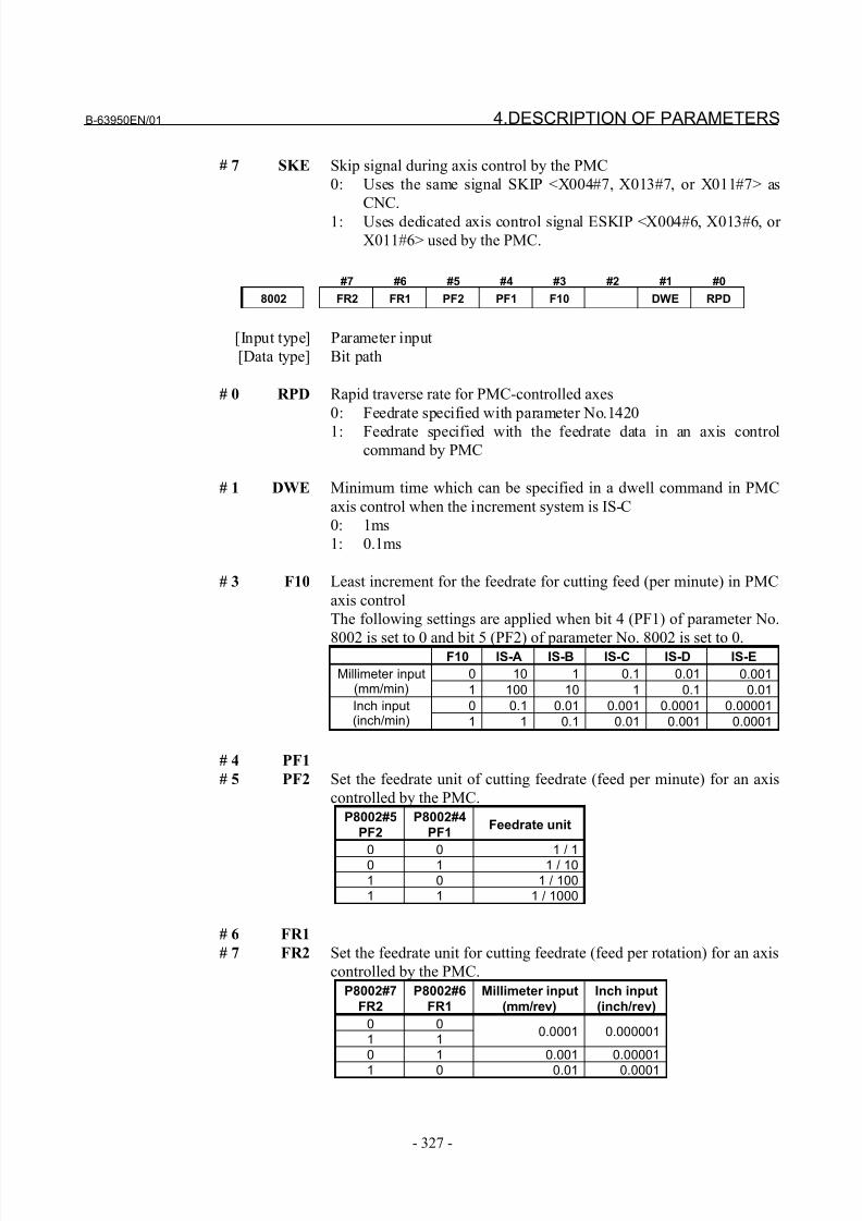
8/21/2019 30i Parameter Manual
http://slidepdf.com/reader/full/30i-parameter-manual 339/493
B-63950EN/01 4.DESCRIPTION OF PARAMETERS
- 327 -
# 7 SKE Skip signal during axis control by the PMC
0: Uses the same signal SKIP <X004#7, X013#7, or X011#7> as
CNC.
1: Uses dedicated axis control signal ESKIP <X004#6, X013#6, or
X011#6> used by the PMC.
#7 #6 #5 #4 #3 #2 #1 #0
8002 FR2 FR1 PF2 PF1 F10 DWE RPD
[Input type] Parameter input
[Data type] Bit path
# 0 RPD Rapid traverse rate for PMC-controlled axes
0: Feedrate specified with parameter No.1420
1: Feedrate specified with the feedrate data in an axis controlcommand by PMC
# 1 DWE Minimum time which can be specified in a dwell command in PMC
axis control when the increment system is IS-C
0: 1ms
1: 0.1ms
# 3 F10 Least increment for the feedrate for cutting feed (per minute) in PMC
axis control
The following settings are applied when bit 4 (PF1) of parameter No.
8002 is set to 0 and bit 5 (PF2) of parameter No. 8002 is set to 0.F10 IS-A IS-B IS-C IS-D IS-E
0 10 1 0.1 0.01 0.001Millimeter input(mm/min) 1 100 10 1 0.1 0.01
0 0.1 0.01 0.001 0.0001 0.00001Inch input(inch/min) 1 1 0.1 0.01 0.001 0.0001
# 4 PF1
# 5 PF2 Set the feedrate unit of cutting feedrate (feed per minute) for an axis
controlled by the PMC.
P8002#5
PF2
P8002#4
PF1Feedrate unit
0 0 1 / 10 1 1 / 101 0 1 / 1001 1 1 / 1000
# 6 FR1
# 7 FR2 Set the feedrate unit for cutting feedrate (feed per rotation) for an axis
controlled by the PMC.
P8002#7
FR2
P8002#6
FR1
Millimeter input
(mm/rev)
Inch input
(inch/rev)
0 01 1
0.0001 0.000001
0 1 0.001 0.00001
1 0 0.01 0.0001
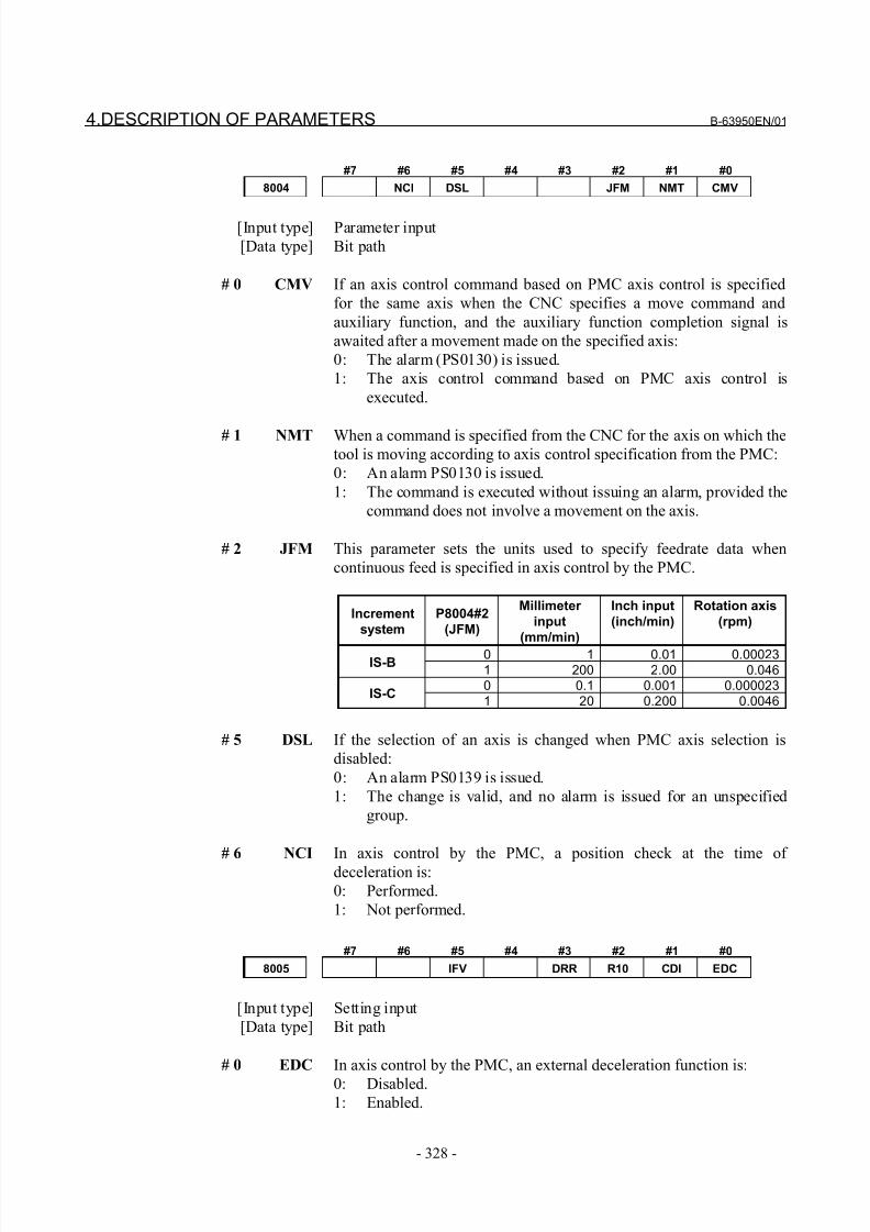
8/21/2019 30i Parameter Manual
http://slidepdf.com/reader/full/30i-parameter-manual 340/493
4.DESCRIPTION OF PARAMETERS B-63950EN/01
- 328 -
#7 #6 #5 #4 #3 #2 #1 #0
8004 NCI DSL JFM NMT CMV
[Input type] Parameter input
[Data type] Bit path
# 0 CMV If an axis control command based on PMC axis control is specified
for the same axis when the CNC specifies a move command and
auxiliary function, and the auxiliary function completion signal is
awaited after a movement made on the specified axis:
0: The alarm (PS0130) is issued.
1: The axis control command based on PMC axis control is
executed.
# 1 NMT When a command is specified from the CNC for the axis on which thetool is moving according to axis control specification from the PMC:
0: An alarm PS0130 is issued.
1: The command is executed without issuing an alarm, provided the
command does not involve a movement on the axis.
# 2 JFM This parameter sets the units used to specify feedrate data when
continuous feed is specified in axis control by the PMC.
Increment
system
P8004#2
(JFM)
Millimeter
input
(mm/min)
Inch input
(inch/min)
Rotation axis
(rpm)
0 1 0.01 0.00023IS-B
1 200 2.00 0.0460 0.1 0.001 0.000023
IS-C1 20 0.200 0.0046
# 5 DSL If the selection of an axis is changed when PMC axis selection is
disabled:
0: An alarm PS0139 is issued.
1: The change is valid, and no alarm is issued for an unspecified
group.
# 6 NCI In axis control by the PMC, a position check at the time of
deceleration is:
0: Performed.
1: Not performed.
#7 #6 #5 #4 #3 #2 #1 #0
8005 IFV DRR R10 CDI EDC
[Input type] Setting input
[Data type] Bit path
# 0 EDC In axis control by the PMC, an external deceleration function is:
0: Disabled.1: Enabled.
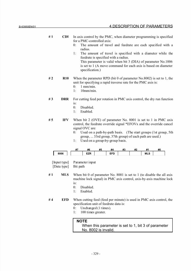
8/21/2019 30i Parameter Manual
http://slidepdf.com/reader/full/30i-parameter-manual 341/493
B-63950EN/01 4.DESCRIPTION OF PARAMETERS
- 329 -
# 1 CDI In axis control by the PMC, when diameter programming is specified
for a PMC-controlled axis:
0: The amount of travel and feedrate are each specified with a
radius.
1: The amount of travel is specified with a diameter while the
feedrate is specified with a radius.
This parameter is valid when bit 3 (DIA) of parameter No.1006
is set to 1 (A move command for each axis is based on diameter
specification.)
# 2 R10 When the parameter RPD (bit 0 of parameter No.8002) is set to 1, the
unit for specifying a rapid traverse rate for the PMC axis is:
0: 1 mm/min.
1: 10mm/min.
# 3 DRR For cutting feed per rotation in PMC axis control, the dry run function
is:
0: Disabled.
1: Enabled.
# 5 IFV When bit 2 (OVE) of parameter No. 8001 is set to 1 in PMC axis
control, the feedrate override signal *EFOVx and the override cancel
signal OVC are:
0: Used on a path-by-path basis. (The start groups (1st group, 5th
group, ... 33rd group, 37th group) of each path are used.)
1: Used on a group-by-group basis.
#7 #6 #5 #4 #3 #2 #1 #0
8006 EZR EFD MLS
[Input type] Parameter input
[Data type] Bit path
# 1 MLS When bit 0 of parameter No. 8001 is set to 1 (to disable the all axis
machine lock signal) in PMC axis control, axis-by-axis machine lock
is:
0: Disabled.
1: Enabled.
# 4 EFD When cutting feed (feed per minute) is used in PMC axis control, the
specification unit of feedrate data is:
0: Unchanged (1 times).
1: 100 times greater.
NOTEWhen this parameter is set to 1, bit 3 of parameter No. 8002 is invalid.
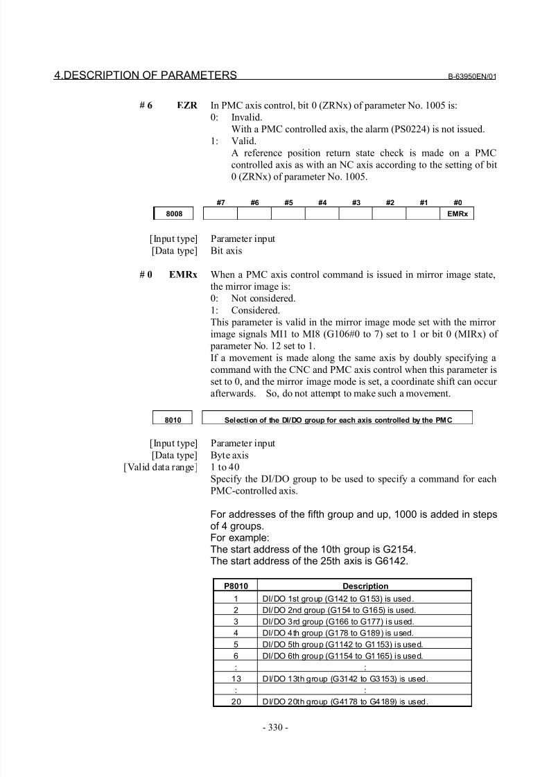
8/21/2019 30i Parameter Manual
http://slidepdf.com/reader/full/30i-parameter-manual 342/493
4.DESCRIPTION OF PARAMETERS B-63950EN/01
- 330 -
# 6 EZR In PMC axis control, bit 0 (ZRNx) of parameter No. 1005 is:
0: Invalid.
With a PMC controlled axis, the alarm (PS0224) is not issued.
1: Valid.
A reference position return state check is made on a PMC
controlled axis as with an NC axis according to the setting of bit
0 (ZRNx) of parameter No. 1005.
#7 #6 #5 #4 #3 #2 #1 #0
8008 EMRx
[Input type] Parameter input
[Data type] Bit axis
# 0 EMRx When a PMC axis control command is issued in mirror image state,the mirror image is:
0: Not considered.
1: Considered.
This parameter is valid in the mirror image mode set with the mirror
image signals MI1 to MI8 (G106#0 to 7) set to 1 or bit 0 (MIRx) of
parameter No. 12 set to 1.
If a movement is made along the same axis by doubly specifying a
command with the CNC and PMC axis control when this parameter is
set to 0, and the mirror image mode is set, a coordinate shift can occur
afterwards. So, do not attempt to make such a movement.
8010 Selection of the DI/DO group for each axis controlled by the PMC
[Input type] Parameter input
[Data type] Byte axis
[Valid data range] 1 to 40
Specify the DI/DO group to be used to specify a command for each
PMC-controlled axis.
For addresses of the fifth group and up, 1000 is added in stepsof 4 groups.For example:The start address of the 10th group is G2154.The start address of the 25th axis is G6142.
P8010 Description
1 DI/DO 1st group (G142 to G153) is used.
2 DI/DO 2nd group (G154 to G165) is used.
3 DI/DO 3rd group (G166 to G177) is used.
4 DI/DO 4th group (G178 to G189) is used.
5 DI/DO 5th group (G1142 to G1153) is used.
6 DI/DO 6th group (G1154 to G1165) is used.
: :
13 DI/DO 13th group (G3142 to G3153) is used.: :
20 DI/DO 20th group (G4178 to G4189) is used.
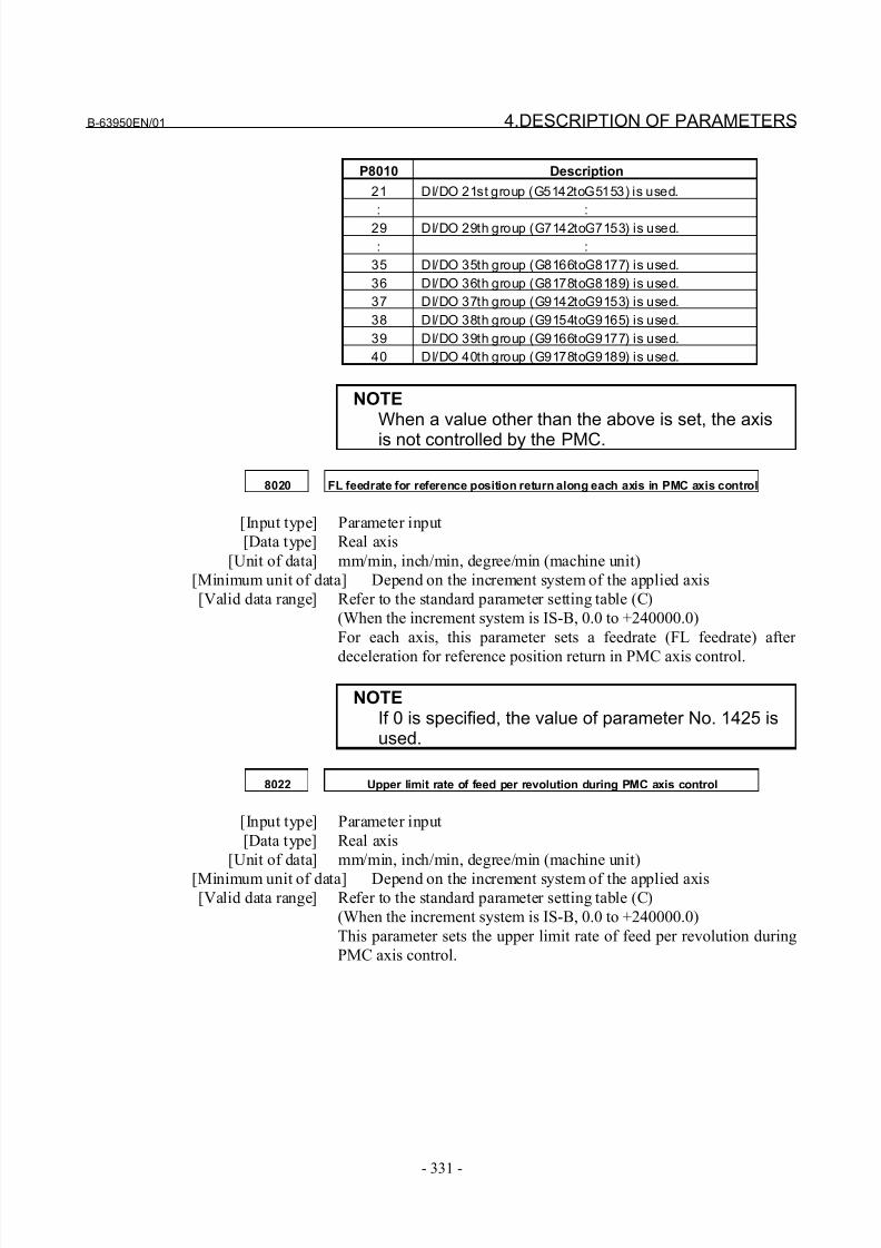
8/21/2019 30i Parameter Manual
http://slidepdf.com/reader/full/30i-parameter-manual 343/493
B-63950EN/01 4.DESCRIPTION OF PARAMETERS
- 331 -
P8010 Description
21 DI/DO 21st group (G5142toG5153) is used.
: :
29 DI/DO 29th group (G7142toG7153) is used.
: :
35 DI/DO 35th group (G8166toG8177) is used.
36 DI/DO 36th group (G8178toG8189) is used.
37 DI/DO 37th group (G9142toG9153) is used.
38 DI/DO 38th group (G9154toG9165) is used.
39 DI/DO 39th group (G9166toG9177) is used.
40 DI/DO 40th group (G9178toG9189) is used.
NOTEWhen a value other than the above is set, the axis
is not controlled by the PMC.
8020 FL feedrate for reference position return along each axis in PMC axis control
[Input type] Parameter input
[Data type] Real axis
[Unit of data] mm/min, inch/min, degree/min (machine unit)
[Minimum unit of data] Depend on the increment system of the applied axis
[Valid data range] Refer to the standard parameter setting table (C)
(When the increment system is IS-B, 0.0 to +240000.0)
For each axis, this parameter sets a feedrate (FL feedrate) after
deceleration for reference position return in PMC axis control.
NOTEIf 0 is specified, the value of parameter No. 1425 isused.
8022 Upper limit rate of feed per revolution during PMC axis control
[Input type] Parameter input
[Data type] Real axis
[Unit of data] mm/min, inch/min, degree/min (machine unit)
[Minimum unit of data] Depend on the increment system of the applied axis[Valid data range] Refer to the standard parameter setting table (C)
(When the increment system is IS-B, 0.0 to +240000.0)
This parameter sets the upper limit rate of feed per revolution during
PMC axis control.
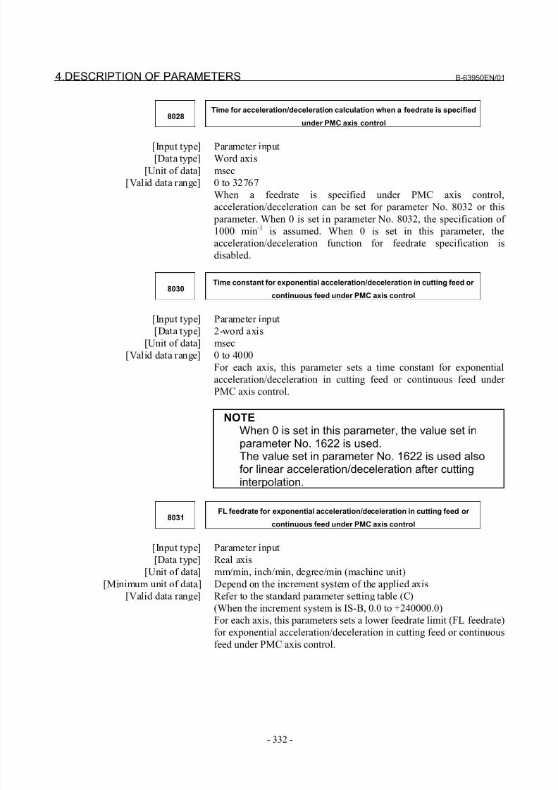
8/21/2019 30i Parameter Manual
http://slidepdf.com/reader/full/30i-parameter-manual 344/493
4.DESCRIPTION OF PARAMETERS B-63950EN/01
- 332 -
8028Time for acceleration/deceleration calculation when a feedrate is specified
under PMC axis control
[Input type] Parameter input
[Data type] Word axis
[Unit of data] msec
[Valid data range] 0 to 32767
When a feedrate is specified under PMC axis control,
acceleration/deceleration can be set for parameter No. 8032 or this
parameter. When 0 is set in parameter No. 8032, the specification of
1000 min-1
is assumed. When 0 is set in this parameter, the
acceleration/deceleration function for feedrate specification is
disabled.
8030Time constant for exponential acceleration/deceleration in cutting feed or
continuous feed under PMC axis control
[Input type] Parameter input
[Data type] 2-word axis
[Unit of data] msec
[Valid data range] 0 to 4000
For each axis, this parameter sets a time constant for exponential
acceleration/deceleration in cutting feed or continuous feed under
PMC axis control.
NOTEWhen 0 is set in this parameter, the value set inparameter No. 1622 is used.The value set in parameter No. 1622 is used alsofor linear acceleration/deceleration after cuttinginterpolation.
8031FL feedrate for exponential acceleration/deceleration in cutting feed or
continuous feed under PMC axis control
[Input type] Parameter input
[Data type] Real axis
[Unit of data] mm/min, inch/min, degree/min (machine unit)
[Minimum unit of data] Depend on the increment system of the applied axis
[Valid data range] Refer to the standard parameter setting table (C)
(When the increment system is IS-B, 0.0 to +240000.0)
For each axis, this parameters sets a lower feedrate limit (FL feedrate)
for exponential acceleration/deceleration in cutting feed or continuous
feed under PMC axis control.
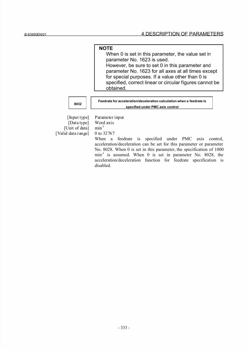
8/21/2019 30i Parameter Manual
http://slidepdf.com/reader/full/30i-parameter-manual 345/493
B-63950EN/01 4.DESCRIPTION OF PARAMETERS
- 333 -
NOTEWhen 0 is set in this parameter, the value set in
parameter No. 1623 is used.However, be sure to set 0 in this parameter andparameter No. 1623 for all axes at all times exceptfor special purposes. If a value other than 0 isspecified, correct linear or circular figures cannot beobtained.
8032Feedrate for acceleration/deceleration calculation when a feedrate is
specified under PMC axis control
[Input type] Parameter input
[Data type] Word axis[Unit of data] min
-1
[Valid data range] 0 to 32767
When a feedrate is specified under PMC axis control,
acceleration/deceleration can be set for this parameter or parameter
No. 8028. When 0 is set in this parameter, the specification of 1000
min-1 is assumed. When 0 is set in parameter No. 8028, the
acceleration/deceleration function for feedrate specification is
disabled.
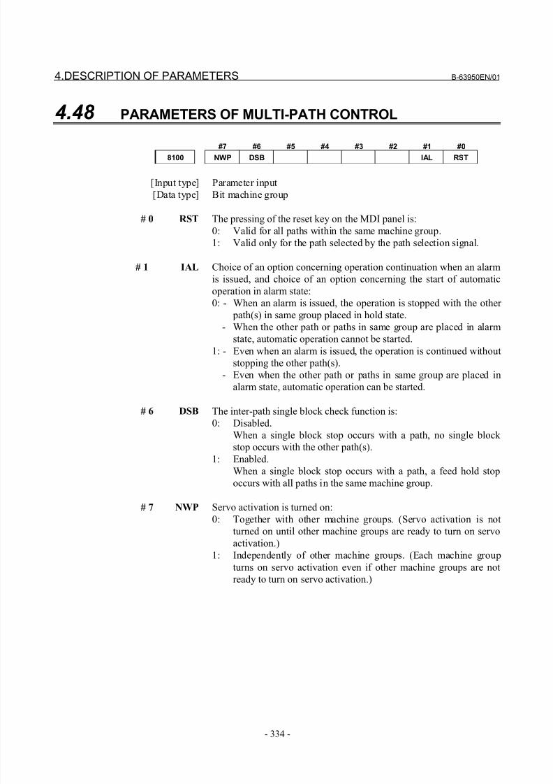
8/21/2019 30i Parameter Manual
http://slidepdf.com/reader/full/30i-parameter-manual 346/493
4.DESCRIPTION OF PARAMETERS B-63950EN/01
- 334 -
4.48 PARAMETERS OF MULTI-PATH CONTROL
#7 #6 #5 #4 #3 #2 #1 #0
8100 NWP DSB IAL RST
[Input type] Parameter input
[Data type] Bit machine group
# 0 RST The pressing of the reset key on the MDI panel is:
0: Valid for all paths within the same machine group.
1: Valid only for the path selected by the path selection signal.
# 1 IAL Choice of an option concerning operation continuation when an alarm
is issued, and choice of an option concerning the start of automatic
operation in alarm state:
0: - When an alarm is issued, the operation is stopped with the other
path(s) in same group placed in hold state.
- When the other path or paths in same group are placed in alarm
state, automatic operation cannot be started.
1: - Even when an alarm is issued, the operation is continued without
stopping the other path(s).
- Even when the other path or paths in same group are placed in
alarm state, automatic operation can be started.
# 6 DSB The inter-path single block check function is:0: Disabled.
When a single block stop occurs with a path, no single block
stop occurs with the other path(s).
1: Enabled.
When a single block stop occurs with a path, a feed hold stop
occurs with all paths in the same machine group.
# 7 NWP Servo activation is turned on:
0: Together with other machine groups. (Servo activation is not
turned on until other machine groups are ready to turn on servo
activation.)
1: Independently of other machine groups. (Each machine group
turns on servo activation even if other machine groups are not
ready to turn on servo activation.)
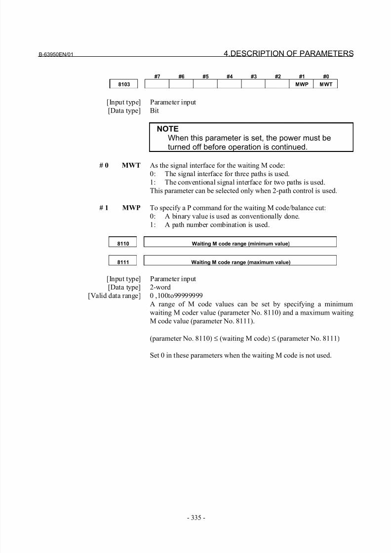
8/21/2019 30i Parameter Manual
http://slidepdf.com/reader/full/30i-parameter-manual 347/493
B-63950EN/01 4.DESCRIPTION OF PARAMETERS
- 335 -
#7 #6 #5 #4 #3 #2 #1 #0
8103 MWP MWT
[Input type] Parameter input
[Data type] Bit
NOTEWhen this parameter is set, the power must beturned off before operation is continued.
# 0 MWT As the signal interface for the waiting M code:
0: The signal interface for three paths is used.
1: The conventional signal interface for two paths is used.
This parameter can be selected only when 2-path control is used.
# 1 MWP To specify a P command for the waiting M code/balance cut:
0: A binary value is used as conventionally done.
1: A path number combination is used.
8110 Waiting M code range (minimum value)
8111 Waiting M code range (maximum value)
[Input type] Parameter input
[Data type] 2-word[Valid data range] 0 ,100to99999999
A range of M code values can be set by specifying a minimum
waiting M coder value (parameter No. 8110) and a maximum waiting
M code value (parameter No. 8111).
(parameter No. 8110) ≤ (waiting M code) ≤ (parameter No. 8111)
Set 0 in these parameters when the waiting M code is not used.
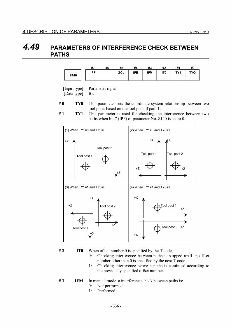
8/21/2019 30i Parameter Manual
http://slidepdf.com/reader/full/30i-parameter-manual 348/493
4.DESCRIPTION OF PARAMETERS B-63950EN/01
- 336 -
4.49 PARAMETERS OF INTERFERENCE CHECK BETWEEN
PATHS
#7 #6 #5 #4 #3 #2 #1 #0
IPF ZCL IFE IFM IT0 TY1 TYO8140
[Input type] Parameter input
[Data type] Bit
# 0 TY0 This parameter sets the coordinate system relationship between two
tool posts based on the tool post of path 1.
# 1 TY1 This parameter is used for checking the interference between two paths when bit 7 (IPF) of parameter No. 8140 is set to 0.
Tool post 2
Tool post 1
+X
+Z
Tool post 2
Tool post 1
+X
+Z
Tool post 2Tool post 1
+X
+Z
+X
+Z
Tool post 2
Tool post 1+X
+Z
+X
+Z
+Z
+X
(1) When TY1=0 and TY0=0 (2) When TY1=0 and TY0=1
(3) When TY1=1 and TY0=0 (4) When TY1=1 and TY0=1
# 2 IT0 When offset number 0 is specified by the T code,
0: Checking interference between paths is stopped until an offset
number other than 0 is specified by the next T code.
1: Checking interference between paths is continued according to
the previously specified offset number.
# 3 IFM In manual mode, a interference check between paths is:
0: Not performed.1: Performed.
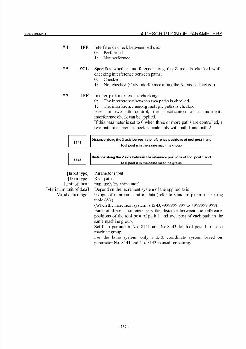
8/21/2019 30i Parameter Manual
http://slidepdf.com/reader/full/30i-parameter-manual 349/493
B-63950EN/01 4.DESCRIPTION OF PARAMETERS
- 337 -
# 4 IFE Interference check between paths is:
0: Performed.
1: Not performed.
# 5 ZCL Specifies whether interference along the Z axis is checked while
checking interference between paths.
0: Checked.
1: Not checked (Only interference along the X axis is checked.)
# 7 IPF In inter-path interference checking:
0: The interference between two paths is checked.
1: The interference among multiple paths is checked.
Even in two-path control, the specification of a multi-path
interference check can be applied.
If this parameter is set to 0 when three or more paths are controlled, atwo-path interference check is made only with path 1 and path 2.
8141Distance along the X axis between the reference positions of tool post 1 and
tool post n in the same machine group
8143Distance along the Z axis between the reference positions of tool post 1 and
tool post n in the same machine group
[Input type] Parameter input
[Data type] Real path
[Unit of data] mm, inch (machine unit)[Minimum unit of data] Depend on the increment system of the applied axis
[Valid data range] 9 digit of minimum unit of data (refer to standard parameter setting
table (A) )
(When the increment system is IS-B, -999999.999 to +999999.999)
Each of these parameters sets the distance between the reference
positions of the tool post of path 1 and tool post of each path in the
same machine group.
Set 0 in parameter No. 8141 and No.8143 for tool post 1 of each
machine group.
For the lathe system, only a Z-X coordinate system based on
parameter No. 8141 and No. 8143 is used for setting.
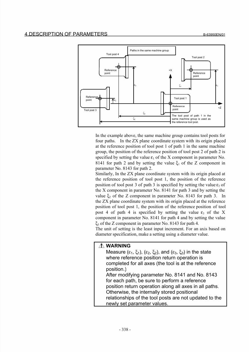
8/21/2019 30i Parameter Manual
http://slidepdf.com/reader/full/30i-parameter-manual 350/493
4.DESCRIPTION OF PARAMETERS B-63950EN/01
- 338 -
Tool post 4
Tool post 3
Tool post 2
The tool post of path 1 in the
same machine group is used as
the reference tool post.
+X
+Z
ζ1 ε1
ε3
Paths in the same machine group
ε2
ζ3
ζ2
Tool post 1Referencepoint
Referencepoint Reference
point
Referencepoint
In the example above, the same machine group contains tool posts for
four paths. In the ZX plane coordinate system with its origin placed
at the reference position of tool post 1 of path 1 in the same machine
group, the position of the reference position of tool post 2 of path 2 is
specified by setting the value ε1 of the X component in parameter No.
8141 for path 2 and by setting the value ξ1 of the Z component in
parameter No. 8143 for path 2.
Similarly, In the ZX plane coordinate system with its origin placed at
the reference position of tool post 1, the position of the reference
position of tool post 3 of path 3 is specified by setting the value ε2 of the X component in parameter No. 8141 for path 3 and by setting the
value ξ2 of the Z component in parameter No. 8143 for path 3. In
the ZX plane coordinate system with its origin placed at the reference
position of tool post 1, the position of the reference position of tool
post 4 of path 4 is specified by setting the value ε3 of the X
component in parameter No. 8141 for path 4 and by setting the value
ξ3 of the Z component in parameter No. 8143 for path 4.
The unit of setting is the least input increment. For an axis based on
diameter specification, make a setting using a diameter value.
WARNINGMeasure (ε1, ξ1), (ε2, ξ2), and (ε3, ξ3) in the statewhere reference position return operation iscompleted for all axes (the tool is at the referenceposition.) After modifying parameter No. 8141 and No. 8143for each path, be sure to perform a referenceposition return operation along all axes in all paths.Otherwise, the internally stored positionalrelationships of the tool posts are not updated to thenewly set parameter values.
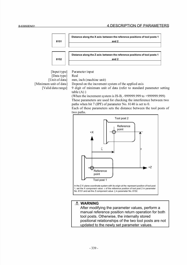
8/21/2019 30i Parameter Manual
http://slidepdf.com/reader/full/30i-parameter-manual 351/493
B-63950EN/01 4.DESCRIPTION OF PARAMETERS
- 339 -
Distance along the X axis between the reference positions of tool posts 1
and 28151
Distance along the Z axis between the reference positions of tool posts 1
and 28152
[Input type] Parameter input
[Data type] Real
[Unit of data] mm, inch (machine unit)
[Minimum unit of data] Depend on the increment system of the applied axis
[Valid data range] 9 digit of minimum unit of data (refer to standard parameter setting
table (A) )(When the increment system is IS-B, -999999.999 to +999999.999)
These parameters are used for checking the interference between two
paths when bit 7 (IPF) of parameter No. 8140 is set to 0.
Each of these parameters sets the distance between the tool posts of
two paths.
Tool post 2
Tool post 1
+X
+Z
ζ ε
In the Z-X plane coordinate system with its origin at the represent position of tool post1, set the X component value ε of the reference position of tool post 2 in parameter
No. 8151 and set the Z component value ξ in parameter No. 8152.
Referencepoint
Referencepoint
WARNING After modifying the parameter values, perform amanual reference position return operation for bothtool posts. Otherwise, the internally storedpositional relationships of the two tool posts are notupdated to the newly set parameter values.
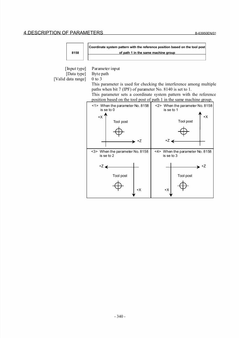
8/21/2019 30i Parameter Manual
http://slidepdf.com/reader/full/30i-parameter-manual 352/493
4.DESCRIPTION OF PARAMETERS B-63950EN/01
- 340 -
Coordinate system pattern with the reference position based on the tool post
of path 1 in the same machine group8158
[Input type] Parameter input
[Data type] Byte path
[Valid data range] 0 to 3
This parameter is used for checking the interference among multiple
paths when bit 7 (IPF) of parameter No. 8140 is set to 1.
This parameter sets a coordinate system pattern with the reference
position based on the tool post of path 1 in the same machine group.
<1> When the parameter No. 8158is se to 0
Tool post+X
+Z
<3> When the parameter No. 8158is se to 2
Tool post
+X
+Z
Tool post
<2> When the parameter No. 8158is se to 1
+X
+Z
<4> When the parameter No. 8158is se to 3
Tool post
+X
+Z
8/21/2019 30i Parameter Manual
http://slidepdf.com/reader/full/30i-parameter-manual 353/493
B-63950EN/01 4.DESCRIPTION OF PARAMETERS
- 341 -
4.50 PARAMETERS OF AXIS RECOMPOSITION AND
SUPERIMPOSED CONTROL
#7 #6 #5 #4 #3 #2 #1 #0
8160 NRS SPE NCS AXS
[Input type] Parameter input
[Data type] Bit path
# 4 AXS When the axis movement in-progress signal (Fn102) or the axis
movement direction signal (Fn106) of the slave axis in superimposed
control is output:
0: State output is performed according to the result of addingsuperimposed move pulses.
1: State output is performed according to the result of movement
along each axis instead of superimposed move pulses.
# 5 NCS If an overtravel alarm is issued for an axis under synchronous,
composite, or superimposed control, synchronous, composite, or
superimposed control is:
0: Released.
1: Not released.
NOTE After updating the value of this parameter, perform amanual reference position return operation for bothtool posts. Otherwise, the internally stored positionalrelationships of the two tool posts are not updated tothe newly set parameter value.
# 6 SPE The synchronization deviation is:
0: The difference between the positioning deviation of the master
axis and that of the slave axis.
1: The difference between the positioning deviation of the master
axis and that of the slave axis plus the acceleration/deceleration
delay.
NOTE1 When the master and slave axes have different
acceleration/deceleration time constants, set 1.2 SPE is valid when bit 1 (SERx) of parameter No. 8162
is set to 1. SPE is used to find a synchronizationdeviation for comparison with parameter No. 8181.
# 7 NRS When the system is reset, synchronous, composite, or superimposed
control is:0: Released.
1: Not released.
8/21/2019 30i Parameter Manual
http://slidepdf.com/reader/full/30i-parameter-manual 354/493
4.DESCRIPTION OF PARAMETERS B-63950EN/01
- 342 -
#7 #6 #5 #4 #3 #2 #1 #0
8161 NSR CRZ NMR
[Input type] Parameter input
[Data type] Bit
# 0 NMR When an axis subject to composite control is placed in servo-off state:
0: Composite control is stopped
1: Composite control is not stopped, provided bit 0 (FUP) of
parameter No.1819 is set to 1 to disable follow-up for the axis.
# 5 CRZ If the state of the composite control signal is switched in composite
control on two axes under Cs contour control, the reference position
establishment state of the two axes in composite control is:
0: Maintained. (The unestablished state is not assumed.)1: Assumed to be unestablished.
# 7 NSR When servo-off occurs with an axis in synchronous control:
0: Synchronous control is canceled.
1: Synchronous control is not canceled if follow-up operation is
disabled for the axis (with bit 0 (FUPx) of parameter No. 1819
set to 1).
#7 #6 #5 #4 #3 #2 #1 #0
8162 MUMx MCDx MPSx MPMx OMRx PKUx SERx SMRx
[Input type] Parameter input
[Data type] Bit axis
# 0 SMRx Synchronous mirror-image control is:
0: Not applied. (The master and slave axes move in the same
direction.)
1: Applied. (The master and slave axes move in opposite
directions.)
# 1 SERx The synchronization deviation is:
0: Not detected.
1: Detected.
NOTEWhen both master and slave axes move insynchronization, the positioning deviations of thecorresponding axes are compared with each other.If the difference is greater than or equal to the valuespecified in parameter No.8181, an alarm occurs.When either axis is in the parking or machine-locked state, however, the synchronization
deviation is not detected. If the master axis andslave axis are in the same path, synchronizationdeviation detection cannot be performed.
8/21/2019 30i Parameter Manual
http://slidepdf.com/reader/full/30i-parameter-manual 355/493
B-63950EN/01 4.DESCRIPTION OF PARAMETERS
- 343 -
# 2 PKUx In the parking state,
0: The absolute, relative, and machine coordinates are not updated.
1: The absolute and relative coordinates are updated. The machine
coordinates are not updated.
NOTE1 With an axis for which polar coordinate interpolation
is specified, set this parameter to 1. If thisparameter is set to 0, a coordinate shift can occur when a single block stop or feed hold is performed inthe polar coordinate interpolation mode.
2 With an axis that is set to function as a synchronous
master axis and synchronous slave axis at the sametime (with bit 1 (SYWx) of parameter No. 8167), setthis parameter to 1.
3 With an axis specified in the three-dimensionalcoordinate conversion mode, set this parameter to 1.If this parameter is set to 0, the alarm (PS0367) isissued.
# 3 OMRx Superimposed mirror-image control is:
0: Not applied. (The superimposed pulse is simply added.)
1: Applied. (The inverted superimposed pulse is added.)
# 4 MPMx When composite control is started, the workpiece coordinate system
is:
0: Not set automatically.
1: Set automatically.
NOTEWhen the workpiece coordinate system isautomatically set at the start of composite control, itis calculated from the following: Current machinecoordinates and the workpiece coordinates at the
reference point of each axis (parameter No.8184).
# 5 MPSx When composite control is terminated, the workpiece coordinate
system is:
0: Not set automatically.
1: Set automatically.
NOTEWhen the workpiece coordinate system isautomatically set at the end of composite control, it iscalculated from the following: Current machine
coordinates and the workpiece coordinates at thereference point of each axis under composite control(parameter No.1250)
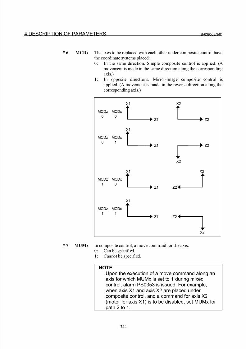
8/21/2019 30i Parameter Manual
http://slidepdf.com/reader/full/30i-parameter-manual 356/493
4.DESCRIPTION OF PARAMETERS B-63950EN/01
- 344 -
# 6 MCDx The axes to be replaced with each other under composite control have
the coordinate systems placed:
0: In the same direction. Simple composite control is applied. (A
movement is made in the same direction along the corresponding
axis.)
1: In opposite directions. Mirror-image composite control is
applied. (A movement is made in the reverse direction along the
corresponding axis.)
MCDz MCDx
0 0Z1
X1
Z2
X2
MCDz MCDx
0 1Z1
X1
Z2
MCDz MCDx
1 0
X2
MCDz MCDx
1 1Z1
X1
Z2
X2
X2
Z1
X1
Z2
# 7 MUMx In composite control, a move command for the axis:0: Can be specified.
1: Cannot be specified.
NOTEUpon the execution of a move command along anaxis for which MUMx is set to 1 during mixedcontrol, alarm PS0353 is issued. For example,when axis X1 and axis X2 are placed under composite control, and a command for axis X2(motor for axis X1) is to be disabled, set MUMx for
path 2 to 1.
8/21/2019 30i Parameter Manual
http://slidepdf.com/reader/full/30i-parameter-manual 357/493
B-63950EN/01 4.DESCRIPTION OF PARAMETERS
- 345 -
#7 #6 #5 #4 #3 #2 #1 #0
8163 NUMx MMIx SMIx SCDx SCMx SPSx SPMx MDXx
[Input type] Parameter input
[Data type] Bit axis
# 0 MDXx In composite control, the current position (absolute or relative
coordinates) display indicates:
0: Coordinates in the local system.
1: Coordinates in the other system under mixed control.
# 1 SPMx When synchronous control is started, automatic workpiece coordinate
system setting for the master axis is
0: Not Performed.
1: Performed.
NOTEWhen a workpiece coordinate system isautomatically set at the start of synchronouscontrol, the workpiece coordinate system iscalculated from the current machine coordinatesand the workpiece coordinates of each axis at thereference position set in parameter No.8185.
# 2 SPSx When synchronous control terminates, automatic workpiece
coordinate system setting for the master axis is:
0: Not performed.
1: Performed.
NOTEWhen a workpiece coordinate system isautomatically set at the end of synchronous control,the workpiece coordinate system is calculated fromthe current machine coordinates and the workpiececoordinates for each axis at the reference position
set in parameter No.1250.
# 3 SCMx When workpiece coordinates are calculated in synchronous control:
0: The workpiece coordinates are calculated from the machine
coordinates of the slave axis.
1: The workpiece coordinates are calculated from the machine
coordinates of the master axis and slave axis.
# 4 SCDx The positive (+) directions of the master axis and slave axis in the
coordinate system in synchronous control are:
0: Identical.
1: Opposite.
Set the parameters SPMx, SPSx, SCMx, and SCDx for the master axis.These settings are referenced during automatic workpiece coordinate
setting for the master axis at the start of synchronous control.
8/21/2019 30i Parameter Manual
http://slidepdf.com/reader/full/30i-parameter-manual 358/493
4.DESCRIPTION OF PARAMETERS B-63950EN/01
- 346 -
# 5 SMIx In synchronous control, the manual handle interruption amount for the
master axis or the mirror image mode is:
0: Reflected in the slave axis.
1: Not reflected in the slave axis.
When this bit (SMIx) is set to 0
Manual handle interruption :
To the travel distance along the slave axis, the interruption
amount of the master axis is also added.
Mirror image :
When mirror image is applied to the master axis, mirror image is
also applied to the slave axis.
When this bit (SMIx) is set to 1Manual handle interruption :
To the travel distance along the slave axis, the interruption
amount of the master axis is not added.
Mirror image :
Even when mirror image is applied to the master axis, mirror
image is not applied to the slave axis.
# 6 MMIx For a composite control axis, manual handle interruption under
composite control is:
0: Enabled.
1: Disabled.
# 7 NUMx When neither synchronous control nor composite control is applied, a
move command for the axis is:
0: Not disabled.
1: Disabled.
NOTEIf a move command is specified for an axis withNUMx set to 1 when neither synchronous controlnor composite control is applied, alarm PS0353 isissued.
#7 #6 #5 #4 #3 #2 #1 #0
SOKx OPSx MCEx MCSx MWEx MWSx8164
SOKx OPSx MCEx MCSx
[Input type] Parameter input
[Data type] Bit axis
# 0 MWSx In automatic workpiece coordinate system setting, performed when
composite control is started, a workpiece shift and position offset are:
0: Not considered.
1: Considered.
8/21/2019 30i Parameter Manual
http://slidepdf.com/reader/full/30i-parameter-manual 359/493
B-63950EN/01 4.DESCRIPTION OF PARAMETERS
- 347 -
NOTEMWSx is enabled when bit 4 (MPMx) of parameter
No.8162 is set to 1.
# 1 MWEx In automatic workpiece coordinate system setting, performed when
composite control is canceled, a workpiece shift and position offset
are:
0: Not considered.
1: Considered.
NOTEMWEx is enabled when bit 5 (MPSx) of parameter No.8162 is set to 1.
# 2 MCSx In automatic workpiece coordinate system setting, performed when
composite control is started:
0: A workpiece coordinate system is automatically set in the same
way as normal.
1: The coordinate system of the other path subject to axis
recomposition is used.
NOTEMCSx is enabled when bit 4 (MPMx) of parameter No.8162 is set to 1.
# 3 MCEx In automatic workpiece coordinate system setting, performed when
composite control is canceled:
0: A workpiece coordinate system is automatically set in the same
way as normal.
1: The coordinate system of the other path subject to axis
recomposition is used.
NOTEMCEx is enabled when bit 5 (MPSx) of parameter No.8162 is set to 1.
# 5 OPSx When superimposed control is canceled, control in which an amount
of movement along a master axis subject to superimposed control is
added to the workpiece coordinate of a slave axis is:
0: Not applied.
1: Applied.
# 6 SOKx If a master axis subject to superimposed control is also subject to
synchronous control:
0: An alarm is issued when superimposed control is started during
synchronous control.
1: No alarm is issued when superimposed control is started during
synchronous control.
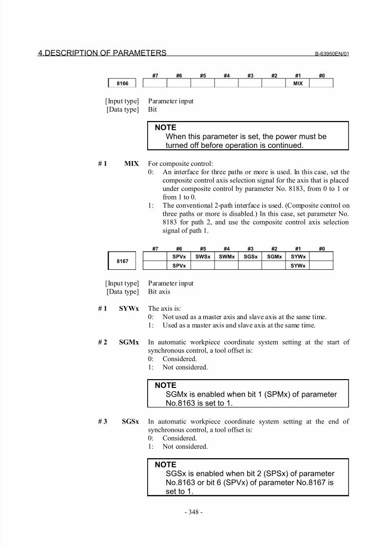
8/21/2019 30i Parameter Manual
http://slidepdf.com/reader/full/30i-parameter-manual 360/493
4.DESCRIPTION OF PARAMETERS B-63950EN/01
- 348 -
#7 #6 #5 #4 #3 #2 #1 #0
8166 MIX
[Input type] Parameter input
[Data type] Bit
NOTEWhen this parameter is set, the power must beturned off before operation is continued.
# 1 MIX For composite control:
0: An interface for three paths or more is used. In this case, set the
composite control axis selection signal for the axis that is placed
under composite control by parameter No. 8183, from 0 to 1 or from 1 to 0.
1: The conventional 2-path interface is used. (Composite control on
three paths or more is disabled.) In this case, set parameter No.
8183 for path 2, and use the composite control axis selection
signal of path 1.
#7 #6 #5 #4 #3 #2 #1 #0
SPVx SWSx SWMx SGSx SGMx SYWx8167
SPVx SYWx
[Input type] Parameter input
[Data type] Bit axis
# 1 SYWx The axis is:
0: Not used as a master axis and slave axis at the same time.
1: Used as a master axis and slave axis at the same time.
# 2 SGMx In automatic workpiece coordinate system setting at the start of
synchronous control, a tool offset is:
0: Considered.
1: Not considered.
NOTESGMx is enabled when bit 1 (SPMx) of parameter No.8163 is set to 1.
# 3 SGSx In automatic workpiece coordinate system setting at the end of
synchronous control, a tool offset is:
0: Considered.
1: Not considered.
NOTESGSx is enabled when bit 2 (SPSx) of parameter No.8163 or bit 6 (SPVx) of parameter No.8167 isset to 1.
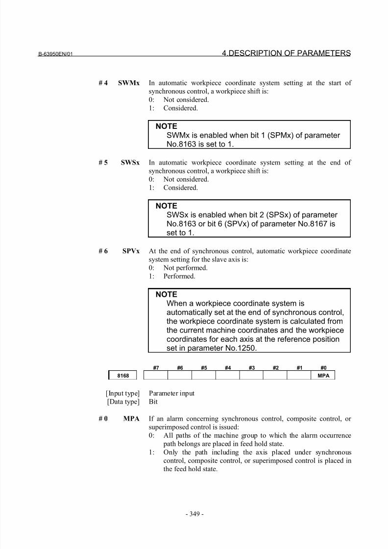
8/21/2019 30i Parameter Manual
http://slidepdf.com/reader/full/30i-parameter-manual 361/493
B-63950EN/01 4.DESCRIPTION OF PARAMETERS
- 349 -
# 4 SWMx In automatic workpiece coordinate system setting at the start of
synchronous control, a workpiece shift is:
0: Not considered.
1: Considered.
NOTESWMx is enabled when bit 1 (SPMx) of parameter No.8163 is set to 1.
# 5 SWSx In automatic workpiece coordinate system setting at the end of
synchronous control, a workpiece shift is:
0: Not considered.
1: Considered.
NOTESWSx is enabled when bit 2 (SPSx) of parameter No.8163 or bit 6 (SPVx) of parameter No.8167 isset to 1.
# 6 SPVx At the end of synchronous control, automatic workpiece coordinate
system setting for the slave axis is:
0: Not performed.
1: Performed.
NOTEWhen a workpiece coordinate system isautomatically set at the end of synchronous control,the workpiece coordinate system is calculated fromthe current machine coordinates and the workpiececoordinates for each axis at the reference positionset in parameter No.1250.
#7 #6 #5 #4 #3 #2 #1 #0
8168 MPA
[Input type] Parameter input
[Data type] Bit
# 0 MPA If an alarm concerning synchronous control, composite control, or
superimposed control is issued:
0: All paths of the machine group to which the alarm occurrence
path belongs are placed in feed hold state.
1: Only the path including the axis placed under synchronous
control, composite control, or superimposed control is placed in
the feed hold state.
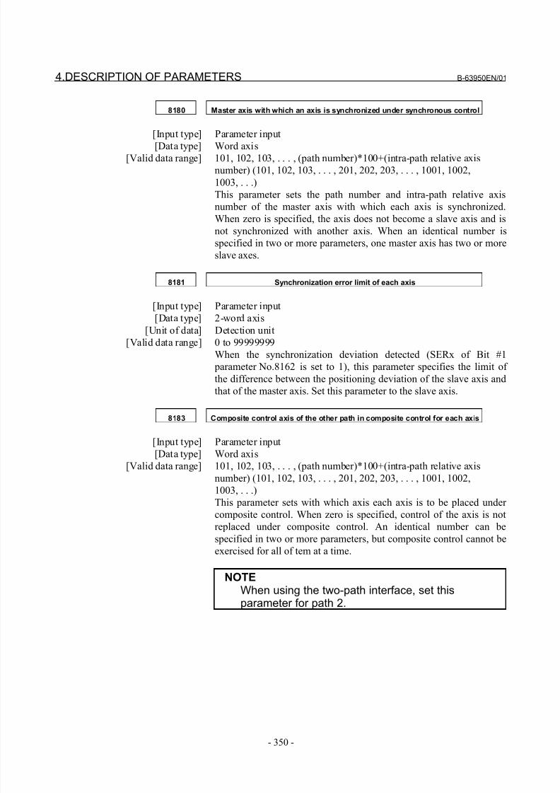
8/21/2019 30i Parameter Manual
http://slidepdf.com/reader/full/30i-parameter-manual 362/493
4.DESCRIPTION OF PARAMETERS B-63950EN/01
- 350 -
8180 Master axis with which an axis is synchronized under synchronous control
[Input type] Parameter input[Data type] Word axis
[Valid data range] 101, 102, 103, . . . , (path number)*100+(intra-path relative axis
number) (101, 102, 103, . . . , 201, 202, 203, . . . , 1001, 1002,
1003, . . .)
This parameter sets the path number and intra-path relative axis
number of the master axis with which each axis is synchronized.
When zero is specified, the axis does not become a slave axis and is
not synchronized with another axis. When an identical number is
specified in two or more parameters, one master axis has two or more
slave axes.
8181 Synchronization error limit of each axis
[Input type] Parameter input
[Data type] 2-word axis
[Unit of data] Detection unit
[Valid data range] 0 to 99999999
When the synchronization deviation detected (SERx of Bit #1
parameter No.8162 is set to 1), this parameter specifies the limit of
the difference between the positioning deviation of the slave axis and
that of the master axis. Set this parameter to the slave axis.
8183 Composite control axis of the other path in composite control for each axis
[Input type] Parameter input
[Data type] Word axis
[Valid data range] 101, 102, 103, . . . , (path number)*100+(intra-path relative axis
number) (101, 102, 103, . . . , 201, 202, 203, . . . , 1001, 1002,
1003, . . .)
This parameter sets with which axis each axis is to be placed under
composite control. When zero is specified, control of the axis is not
replaced under composite control. An identical number can be
specified in two or more parameters, but composite control cannot be
exercised for all of tem at a time.
NOTEWhen using the two-path interface, set thisparameter for path 2.
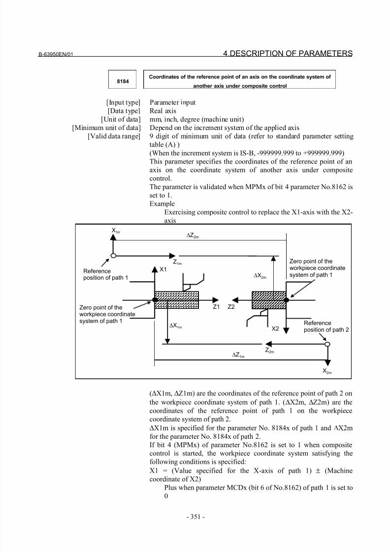
8/21/2019 30i Parameter Manual
http://slidepdf.com/reader/full/30i-parameter-manual 363/493
B-63950EN/01 4.DESCRIPTION OF PARAMETERS
- 351 -
8184Coordinates of the reference point of an axis on the coordinate system of
another axis under composite control
[Input type] Parameter input
[Data type] Real axis
[Unit of data] mm, inch, degree (machine unit)
[Minimum unit of data] Depend on the increment system of the applied axis
[Valid data range] 9 digit of minimum unit of data (refer to standard parameter setting
table (A) )
(When the increment system is IS-B, -999999.999 to +999999.999)
This parameter specifies the coordinates of the reference point of an
axis on the coordinate system of another axis under composite
control.
The parameter is validated when MPMx of bit 4 parameter No.8162 is
set to 1.Example
Exercising composite control to replace the X1-axis with the X2-
axis
X1Referenceposition of path 1
∆Z2m
X1m
Z1m
∆X2m
X2
Z1 Z2Zero point of theworkpiece coordinatesystem of path 1
Zero point of theworkpiece coordinatesystem of path 1
∆Z1m
Z2m
X2m
Referenceposition of path 2
∆X1m
(∆X1m, ∆Z1m) are the coordinates of the reference point of path 2 on
the workpiece coordinate system of path 1. (∆X2m, ∆Z2m) are the
coordinates of the reference point of path 1 on the workpiece
coordinate system of path 2.
∆X1m is specified for the parameter No. 8184x of path 1 and ∆X2m
for the parameter No. 8184x of path 2.
If bit 4 (MPMx) of parameter No.8162 is set to 1 when composite
control is started, the workpiece coordinate system satisfying the
following conditions is specified:
X1 = (Value specified for the X-axis of path 1) ± (Machine
coordinate of X2)
Plus when parameter MCDx (bit 6 of No.8162) of path 1 is set to
0
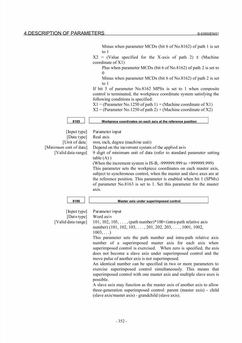
8/21/2019 30i Parameter Manual
http://slidepdf.com/reader/full/30i-parameter-manual 364/493
4.DESCRIPTION OF PARAMETERS B-63950EN/01
- 352 -
Minus when parameter MCDx (bit 6 of No.8162) of path 1 is set
to 1
X2 = (Value specified for the X-axis of path 2) ± (Machine
coordinate of X1)
Plus when parameter MCDx (bit 6 of No.8162) of path 2 is set to
0
Minus when parameter MCDx (bit 6 of No.8162) of path 2 is set
to 1
If bit 5 of parameter No.8162 MPSx is set to 1 when composite
control is terminated, the workpiece coordinate system satisfying the
following conditions is specified:
X1 = (Parameter No.1250 of path 1) + (Machine coordinate of X1)
X2 = (Parameter No.1250 of path 2) + (Machine coordinate of X2)
8185 Workpiece coordinates on each axis at the reference position
[Input type] Parameter input
[Data type] Real axis
[Unit of data] mm, inch, degree (machine unit)
[Minimum unit of data] Depend on the increment system of the applied axis
[Valid data range] 9 digit of minimum unit of data (refer to standard parameter setting
table (A) )
(When the increment system is IS-B, -999999.999 to +999999.999)
This parameter sets the workpiece coordinates on each master axis,
subject to synchronous control, when the master and slave axes are at
the reference position. This parameter is enabled when bit 1 (SPMx)of parameter No.8163 is set to 1. Set this parameter for the master
axis.
8186 Master axis under superimposed control
[Input type] Parameter input
[Data type] Word axis
[Valid data range] 101, 102, 103, . . . , (path number)*100+(intra-path relative axis
number) (101, 102, 103, . . . , 201, 202, 203, . . . , 1001, 1002,
1003, . . .)
This parameter sets the path number and intra-path relative axis
number of a superimposed master axis for each axis when
superimposed control is exercised. When zero is specified, the axis
does not become a slave axis under superimposed control and the
move pulse of another axis is not superimposed.
An identical number can be specified in two or more parameters to
exercise superimposed control simultaneously. This means that
superimposed control with one master axis and multiple slave axes is
possible.
A slave axis may function as the master axis of another axis to allow
three-generation superimposed control: parent (master axis) - child
(slave axis/master axis) - grandchild (slave axis).
8/21/2019 30i Parameter Manual
http://slidepdf.com/reader/full/30i-parameter-manual 365/493
B-63950EN/01 4.DESCRIPTION OF PARAMETERS
- 353 -
In this case, a movement along the child is made by its travel distance
plus the travel distance of the parent, and a movement along the
grandchild is made by its travel distance plus the travel distance of the
child plus the travel distance of the parent.
Example of the relationship of parent (X1 of path 1) - child (X2 of
path 2) - grandchild (X3 of path 3):
The travel distance of X1 is superimposed on X2, and the travel
distances of X1 and X2 are further superimposed on X3.
Parameter No. 8186x of path 2 = 101
Parameter No. 8186x of path 3 = 201
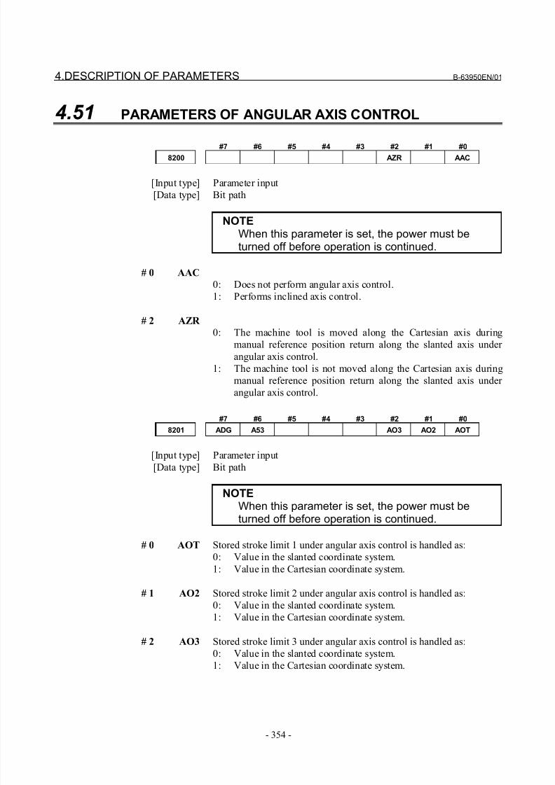
8/21/2019 30i Parameter Manual
http://slidepdf.com/reader/full/30i-parameter-manual 366/493
4.DESCRIPTION OF PARAMETERS B-63950EN/01
- 354 -
4.51 PARAMETERS OF ANGULAR AXIS CONTROL
#7 #6 #5 #4 #3 #2 #1 #0
8200 AZR AAC
[Input type] Parameter input
[Data type] Bit path
NOTEWhen this parameter is set, the power must beturned off before operation is continued.
# 0 AAC0: Does not perform angular axis control.
1: Performs inclined axis control.
# 2 AZR
0: The machine tool is moved along the Cartesian axis during
manual reference position return along the slanted axis under
angular axis control.
1: The machine tool is not moved along the Cartesian axis during
manual reference position return along the slanted axis under
angular axis control.
#7 #6 #5 #4 #3 #2 #1 #0
8201 ADG A53 AO3 AO2 AOT
[Input type] Parameter input
[Data type] Bit path
NOTEWhen this parameter is set, the power must beturned off before operation is continued.
# 0 AOT
Stored stroke limit 1 under angular axis control is handled as:0: Value in the slanted coordinate system.
1: Value in the Cartesian coordinate system.
# 1 AO2 Stored stroke limit 2 under angular axis control is handled as:
0: Value in the slanted coordinate system.
1: Value in the Cartesian coordinate system.
# 2 AO3 Stored stroke limit 3 under angular axis control is handled as:
0: Value in the slanted coordinate system.
1: Value in the Cartesian coordinate system.
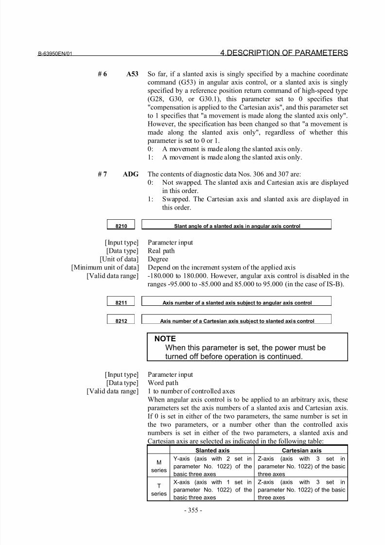
8/21/2019 30i Parameter Manual
http://slidepdf.com/reader/full/30i-parameter-manual 367/493
B-63950EN/01 4.DESCRIPTION OF PARAMETERS
- 355 -
# 6 A53 So far, if a slanted axis is singly specified by a machine coordinate
command (G53) in angular axis control, or a slanted axis is singly
specified by a reference position return command of high-speed type
(G28, G30, or G30.1), this parameter set to 0 specifies that
"compensation is applied to the Cartesian axis", and this parameter set
to 1 specifies that "a movement is made along the slanted axis only".
However, the specification has been changed so that "a movement is
made along the slanted axis only", regardless of whether this
parameter is set to 0 or 1.
0: A movement is made along the slanted axis only.
1: A movement is made along the slanted axis only.
# 7 ADG The contents of diagnostic data Nos. 306 and 307 are:
0: Not swapped. The slanted axis and Cartesian axis are displayed
in this order.1: Swapped. The Cartesian axis and slanted axis are displayed in
this order.
8210 Slant angle of a slanted axis in angular axis control
[Input type] Parameter input
[Data type] Real path
[Unit of data] Degree
[Minimum unit of data] Depend on the increment system of the applied axis
[Valid data range] -180.000 to 180.000. However, angular axis control is disabled in the
ranges -95.000 to -85.000 and 85.000 to 95.000 (in the case of IS-B).
8211 Axis number of a slanted axis subject to angular axis control
8212 Axis number of a Cartesian axis subject to slanted axis control
NOTEWhen this parameter is set, the power must beturned off before operation is continued.
[Input type] Parameter input
[Data type] Word path[Valid data range] 1 to number of controlled axes
When angular axis control is to be applied to an arbitrary axis, these
parameters set the axis numbers of a slanted axis and Cartesian axis.
If 0 is set in either of the two parameters, the same number is set in
the two parameters, or a number other than the controlled axis
numbers is set in either of the two parameters, a slanted axis and
Cartesian axis are selected as indicated in the following table:
Slanted axis Cartesian axis
M
series
Y-axis (axis with 2 set in
parameter No. 1022) of the
basic three axes
Z-axis (axis with 3 set in
parameter No. 1022) of the basic
three axes
T
series
X-axis (axis with 1 set in
parameter No. 1022) of the
basic three axes
Z-axis (axis with 3 set in
parameter No. 1022) of the basic
three axes
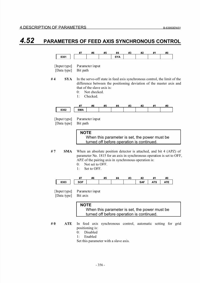
8/21/2019 30i Parameter Manual
http://slidepdf.com/reader/full/30i-parameter-manual 368/493
4.DESCRIPTION OF PARAMETERS B-63950EN/01
- 356 -
4.52 PARAMETERS OF FEED AXIS SYNCHRONOUS CONTROL
#7 #6 #5 #4 #3 #2 #1 #0
8301 SYA
[Input type] Parameter input
[Data type] Bit path
# 4 SYA In the servo-off state in feed axis synchronous control, the limit of the
difference between the positioning deviation of the master axis and
that of the slave axis is:
0: Not checked.
1: Checked.
#7 #6 #5 #4 #3 #2 #1 #0
8302 SMA
[Input type] Parameter input
[Data type] Bit path
NOTEWhen this parameter is set, the power must beturned off before operation is continued.
# 7 SMA When an absolute position detector is attached, and bit 4 (APZ) of
parameter No. 1815 for an axis in synchronous operation is set to OFF,
APZ of the pairing axis in synchronous operation is:
0: Not set to OFF.
1: Set to OFF.
#7 #6 #5 #4 #3 #2 #1 #0
8303 SOF SAF ATS ATE
[Input type] Parameter input
[Data type] Bit axis
NOTEWhen this parameter is set, the power must beturned off before operation is continued.
# 0 ATE In feed axis synchronous control, automatic setting for grid
positioning is:
0: Disabled
1: Enabled
Set this parameter with a slave axis.
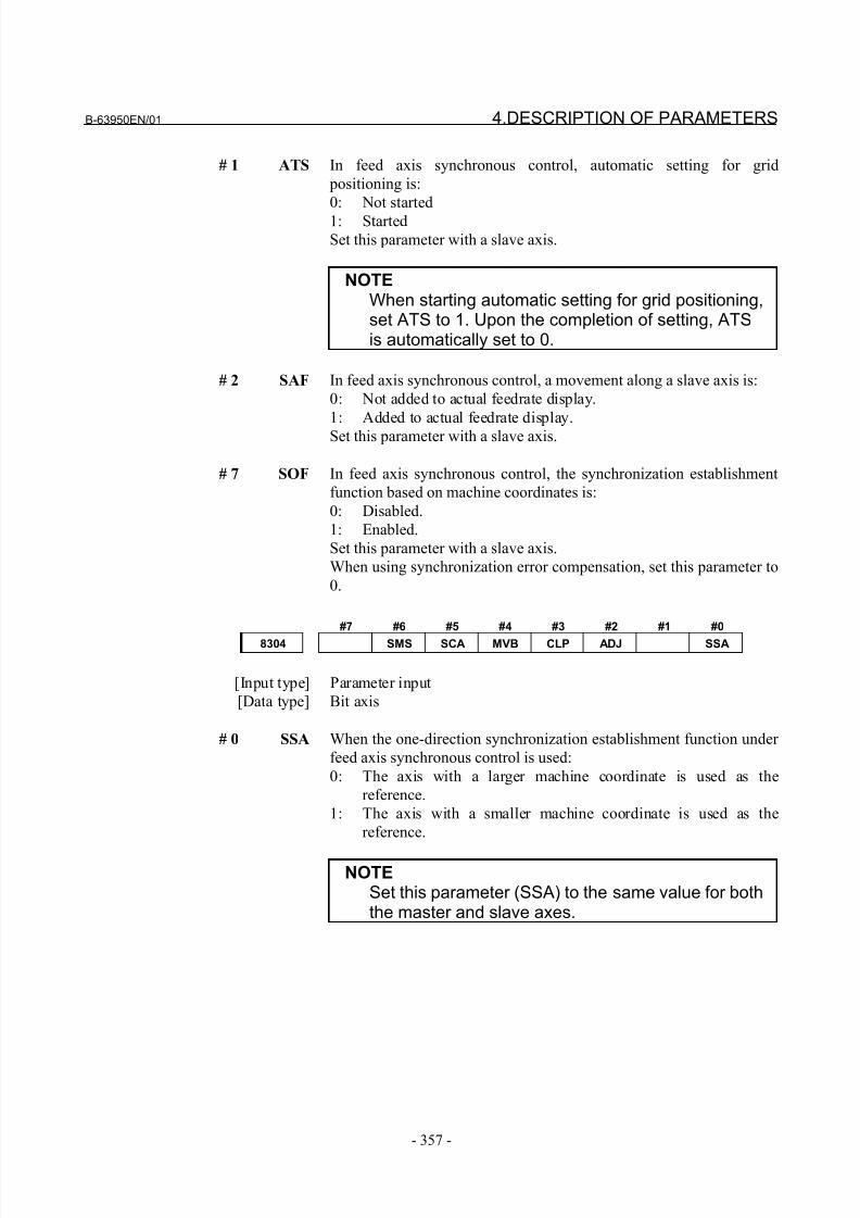
8/21/2019 30i Parameter Manual
http://slidepdf.com/reader/full/30i-parameter-manual 369/493
B-63950EN/01 4.DESCRIPTION OF PARAMETERS
- 357 -
# 1 ATS In feed axis synchronous control, automatic setting for grid
positioning is:
0: Not started
1: Started
Set this parameter with a slave axis.
NOTEWhen starting automatic setting for grid positioning,set ATS to 1. Upon the completion of setting, ATSis automatically set to 0.
# 2 SAF In feed axis synchronous control, a movement along a slave axis is:
0: Not added to actual feedrate display.
1: Added to actual feedrate display.
Set this parameter with a slave axis.
# 7 SOF In feed axis synchronous control, the synchronization establishment
function based on machine coordinates is:
0: Disabled.
1: Enabled.
Set this parameter with a slave axis.
When using synchronization error compensation, set this parameter to
0.
#7 #6 #5 #4 #3 #2 #1 #0
8304 SMS SCA MVB CLP ADJ SSA
[Input type] Parameter input
[Data type] Bit axis
# 0 SSA When the one-direction synchronization establishment function under
feed axis synchronous control is used:
0: The axis with a larger machine coordinate is used as the
reference.
1: The axis with a smaller machine coordinate is used as the
reference.
NOTESet this parameter (SSA) to the same value for boththe master and slave axes.
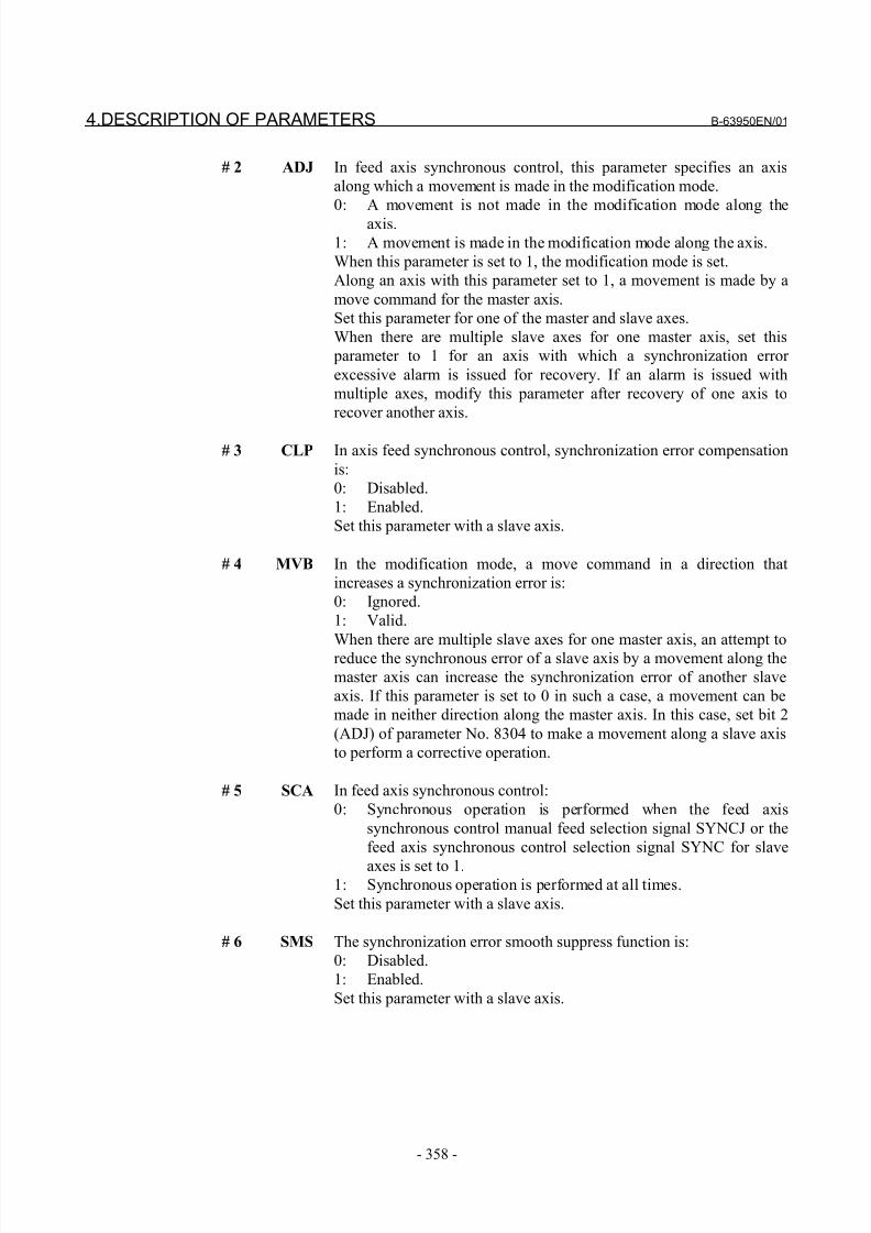
8/21/2019 30i Parameter Manual
http://slidepdf.com/reader/full/30i-parameter-manual 370/493
4.DESCRIPTION OF PARAMETERS B-63950EN/01
- 358 -
# 2 ADJ In feed axis synchronous control, this parameter specifies an axis
along which a movement is made in the modification mode.
0: A movement is not made in the modification mode along the
axis.
1: A movement is made in the modification mode along the axis.
When this parameter is set to 1, the modification mode is set.
Along an axis with this parameter set to 1, a movement is made by a
move command for the master axis.
Set this parameter for one of the master and slave axes.
When there are multiple slave axes for one master axis, set this
parameter to 1 for an axis with which a synchronization error
excessive alarm is issued for recovery. If an alarm is issued with
multiple axes, modify this parameter after recovery of one axis to
recover another axis.
# 3 CLP In axis feed synchronous control, synchronization error compensation
is:
0: Disabled.
1: Enabled.
Set this parameter with a slave axis.
# 4 MVB In the modification mode, a move command in a direction that
increases a synchronization error is:
0: Ignored.
1: Valid.
When there are multiple slave axes for one master axis, an attempt to
reduce the synchronous error of a slave axis by a movement along the
master axis can increase the synchronization error of another slave
axis. If this parameter is set to 0 in such a case, a movement can be
made in neither direction along the master axis. In this case, set bit 2
(ADJ) of parameter No. 8304 to make a movement along a slave axis
to perform a corrective operation.
# 5 SCA In feed axis synchronous control:
0: Synchronous operation is performed when the feed axis
synchronous control manual feed selection signal SYNCJ or the
feed axis synchronous control selection signal SYNC for slave
axes is set to 1.1: Synchronous operation is performed at all times.
Set this parameter with a slave axis.
# 6 SMS The synchronization error smooth suppress function is:
0: Disabled.
1: Enabled.
Set this parameter with a slave axis.
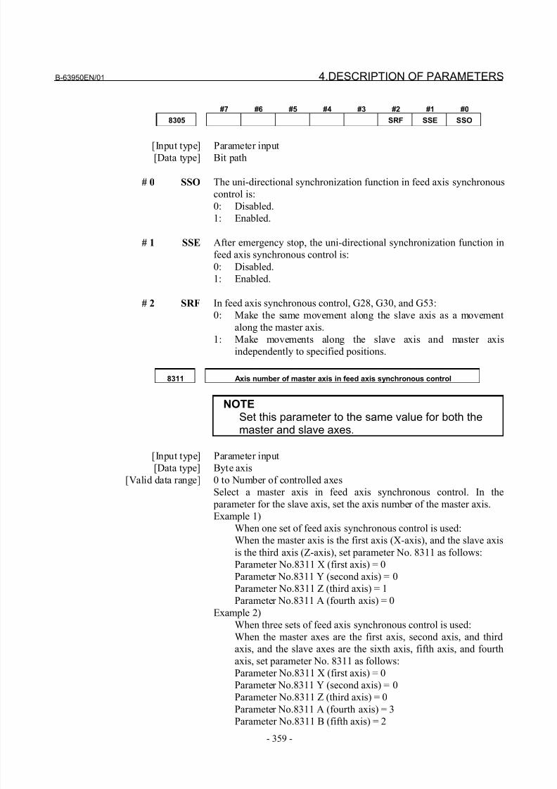
8/21/2019 30i Parameter Manual
http://slidepdf.com/reader/full/30i-parameter-manual 371/493
B-63950EN/01 4.DESCRIPTION OF PARAMETERS
- 359 -
#7 #6 #5 #4 #3 #2 #1 #0
8305 SRF SSE SSO
[Input type] Parameter input
[Data type] Bit path
# 0 SSO The uni-directional synchronization function in feed axis synchronous
control is:
0: Disabled.
1: Enabled.
# 1 SSE After emergency stop, the uni-directional synchronization function in
feed axis synchronous control is:
0: Disabled.
1: Enabled.
# 2 SRF In feed axis synchronous control, G28, G30, and G53:
0: Make the same movement along the slave axis as a movement
along the master axis.
1: Make movements along the slave axis and master axis
independently to specified positions.
8311 Axis number of master axis in feed axis synchronous control
NOTE
Set this parameter to the same value for both themaster and slave axes.
[Input type] Parameter input
[Data type] Byte axis
[Valid data range] 0 to Number of controlled axes
Select a master axis in feed axis synchronous control. In the
parameter for the slave axis, set the axis number of the master axis.
Example 1)
When one set of feed axis synchronous control is used:
When the master axis is the first axis (X-axis), and the slave axis
is the third axis (Z-axis), set parameter No. 8311 as follows:Parameter No.8311 X (first axis) = 0
Parameter No.8311 Y (second axis) = 0
Parameter No.8311 Z (third axis) = 1
Parameter No.8311 A (fourth axis) = 0
Example 2)
When three sets of feed axis synchronous control is used:
When the master axes are the first axis, second axis, and third
axis, and the slave axes are the sixth axis, fifth axis, and fourth
axis, set parameter No. 8311 as follows:
Parameter No.8311 X (first axis) = 0
Parameter No.8311 Y (second axis) = 0
Parameter No.8311 Z (third axis) = 0
Parameter No.8311 A (fourth axis) = 3
Parameter No.8311 B (fifth axis) = 2
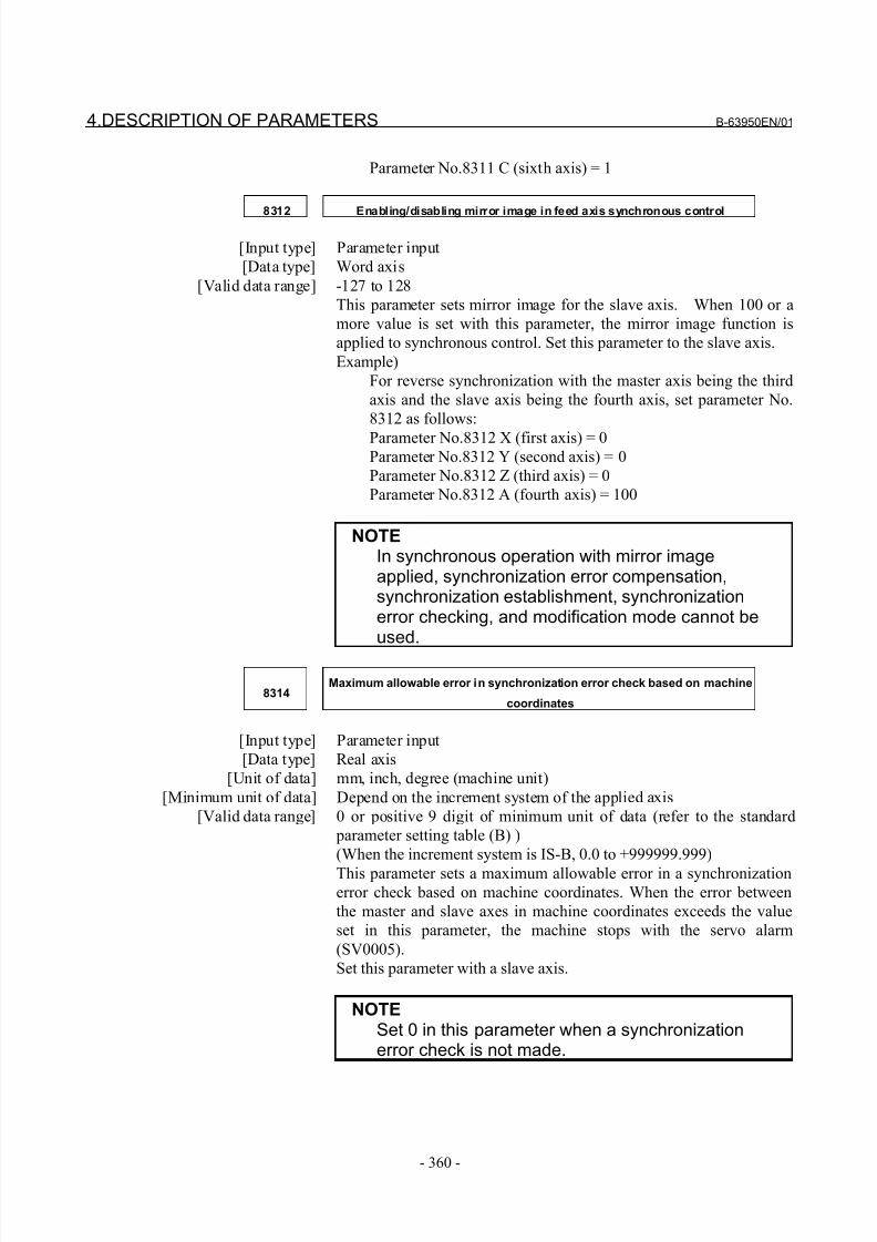
8/21/2019 30i Parameter Manual
http://slidepdf.com/reader/full/30i-parameter-manual 372/493
4.DESCRIPTION OF PARAMETERS B-63950EN/01
- 360 -
Parameter No.8311 C (sixth axis) = 1
8312 Enabling/disabling mirror image in feed axis synchronous control
[Input type] Parameter input
[Data type] Word axis
[Valid data range] -127 to 128
This parameter sets mirror image for the slave axis. When 100 or a
more value is set with this parameter, the mirror image function is
applied to synchronous control. Set this parameter to the slave axis.
Example)
For reverse synchronization with the master axis being the third
axis and the slave axis being the fourth axis, set parameter No.
8312 as follows:
Parameter No.8312 X (first axis) = 0Parameter No.8312 Y (second axis) = 0
Parameter No.8312 Z (third axis) = 0
Parameter No.8312 A (fourth axis) = 100
NOTEIn synchronous operation with mirror imageapplied, synchronization error compensation,synchronization establishment, synchronizationerror checking, and modification mode cannot beused.
8314Maximum allowable error in synchronization error check based on machine
coordinates
[Input type] Parameter input
[Data type] Real axis
[Unit of data] mm, inch, degree (machine unit)
[Minimum unit of data] Depend on the increment system of the applied axis
[Valid data range] 0 or positive 9 digit of minimum unit of data (refer to the standard
parameter setting table (B) )
(When the increment system is IS-B, 0.0 to +999999.999)
This parameter sets a maximum allowable error in a synchronizationerror check based on machine coordinates. When the error between
the master and slave axes in machine coordinates exceeds the value
set in this parameter, the machine stops with the servo alarm
(SV0005).
Set this parameter with a slave axis.
NOTESet 0 in this parameter when a synchronizationerror check is not made.
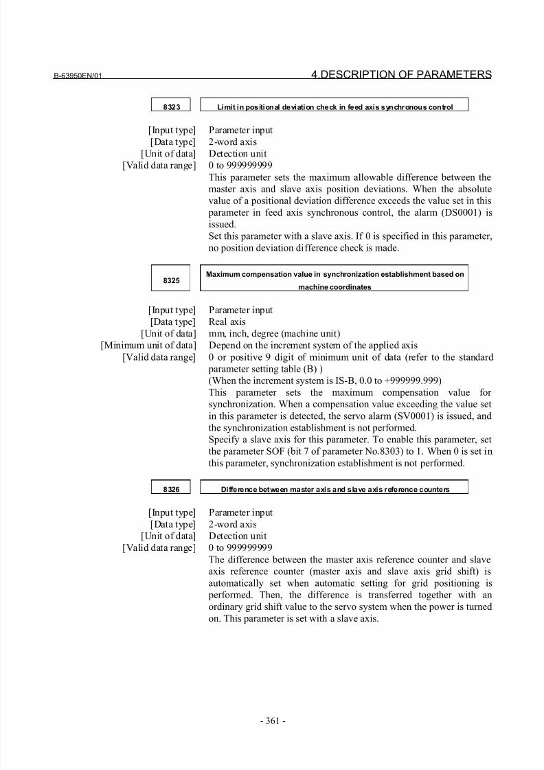
8/21/2019 30i Parameter Manual
http://slidepdf.com/reader/full/30i-parameter-manual 373/493
B-63950EN/01 4.DESCRIPTION OF PARAMETERS
- 361 -
8323 Limit in positional deviation check in feed axis synchronous control
[Input type] Parameter input[Data type] 2-word axis
[Unit of data] Detection unit
[Valid data range] 0 to 999999999
This parameter sets the maximum allowable difference between the
master axis and slave axis position deviations. When the absolute
value of a positional deviation difference exceeds the value set in this
parameter in feed axis synchronous control, the alarm (DS0001) is
issued.
Set this parameter with a slave axis. If 0 is specified in this parameter,
no position deviation difference check is made.
8325Maximum compensation value in synchronization establishment based on
machine coordinates
[Input type] Parameter input
[Data type] Real axis
[Unit of data] mm, inch, degree (machine unit)
[Minimum unit of data] Depend on the increment system of the applied axis
[Valid data range] 0 or positive 9 digit of minimum unit of data (refer to the standard
parameter setting table (B) )
(When the increment system is IS-B, 0.0 to +999999.999)
This parameter sets the maximum compensation value for
synchronization. When a compensation value exceeding the value setin this parameter is detected, the servo alarm (SV0001) is issued, and
the synchronization establishment is not performed.
Specify a slave axis for this parameter. To enable this parameter, set
the parameter SOF (bit 7 of parameter No.8303) to 1. When 0 is set in
this parameter, synchronization establishment is not performed.
8326 Difference between master axis and slave axis reference counters
[Input type] Parameter input
[Data type] 2-word axis
[Unit of data] Detection unit[Valid data range] 0 to 999999999
The difference between the master axis reference counter and slave
axis reference counter (master axis and slave axis grid shift) is
automatically set when automatic setting for grid positioning is
performed. Then, the difference is transferred together with an
ordinary grid shift value to the servo system when the power is turned
on. This parameter is set with a slave axis.
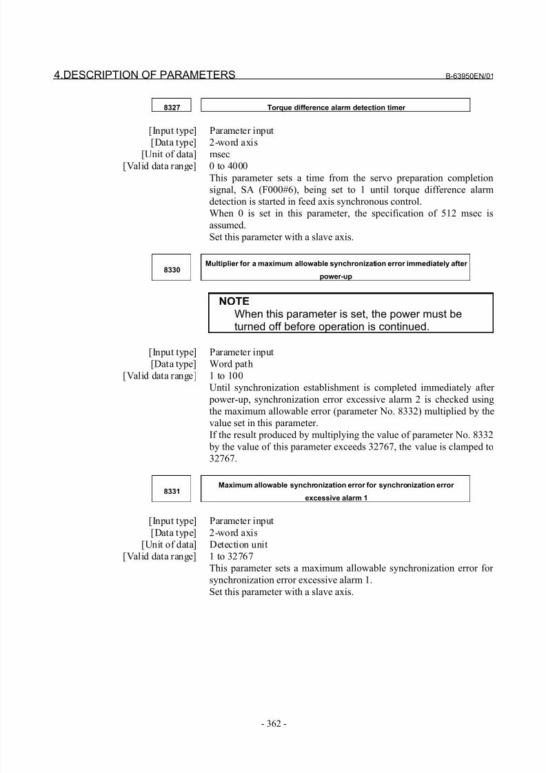
8/21/2019 30i Parameter Manual
http://slidepdf.com/reader/full/30i-parameter-manual 374/493
4.DESCRIPTION OF PARAMETERS B-63950EN/01
- 362 -
8327 Torque difference alarm detection timer
[Input type] Parameter input[Data type] 2-word axis
[Unit of data] msec
[Valid data range] 0 to 4000
This parameter sets a time from the servo preparation completion
signal, SA (F000#6), being set to 1 until torque difference alarm
detection is started in feed axis synchronous control.
When 0 is set in this parameter, the specification of 512 msec is
assumed.
Set this parameter with a slave axis.
8330
Multiplier for a maximum allowable synchronization error immediately after
power-up
NOTEWhen this parameter is set, the power must beturned off before operation is continued.
[Input type] Parameter input
[Data type] Word path
[Valid data range] 1 to 100
Until synchronization establishment is completed immediately after
power-up, synchronization error excessive alarm 2 is checked using
the maximum allowable error (parameter No. 8332) multiplied by the
value set in this parameter.
If the result produced by multiplying the value of parameter No. 8332
by the value of this parameter exceeds 32767, the value is clamped to
32767.
8331Maximum allowable synchronization error for synchronization error
excessive alarm 1
[Input type] Parameter input
[Data type] 2-word axis
[Unit of data] Detection unit[Valid data range] 1 to 32767
This parameter sets a maximum allowable synchronization error for
synchronization error excessive alarm 1.
Set this parameter with a slave axis.
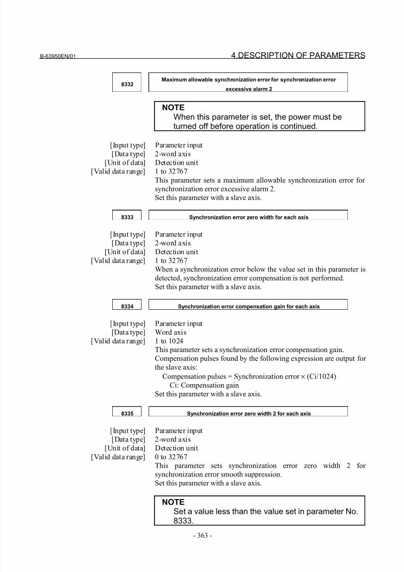
8/21/2019 30i Parameter Manual
http://slidepdf.com/reader/full/30i-parameter-manual 375/493
B-63950EN/01 4.DESCRIPTION OF PARAMETERS
- 363 -
8332Maximum allowable synchronization error for synchronization error
excessive alarm 2
NOTEWhen this parameter is set, the power must beturned off before operation is continued.
[Input type] Parameter input
[Data type] 2-word axis
[Unit of data] Detection unit
[Valid data range] 1 to 32767
This parameter sets a maximum allowable synchronization error for
synchronization error excessive alarm 2.
Set this parameter with a slave axis.
8333 Synchronization error zero width for each axis
[Input type] Parameter input
[Data type] 2-word axis
[Unit of data] Detection unit
[Valid data range] 1 to 32767
When a synchronization error below the value set in this parameter is
detected, synchronization error compensation is not performed.
Set this parameter with a slave axis.
8334 Synchronization error compensation gain for each axis
[Input type] Parameter input
[Data type] Word axis
[Valid data range] 1 to 1024
This parameter sets a synchronization error compensation gain.
Compensation pulses found by the following expression are output for
the slave axis:
Compensation pulses = Synchronization error × (Ci/1024)
Ci: Compensation gain
Set this parameter with a slave axis.
8335 Synchronization error zero width 2 for each axis
[Input type] Parameter input
[Data type] 2-word axis
[Unit of data] Detection unit
[Valid data range] 0 to 32767
This parameter sets synchronization error zero width 2 for
synchronization error smooth suppression.
Set this parameter with a slave axis.
NOTESet a value less than the value set in parameter No.8333.
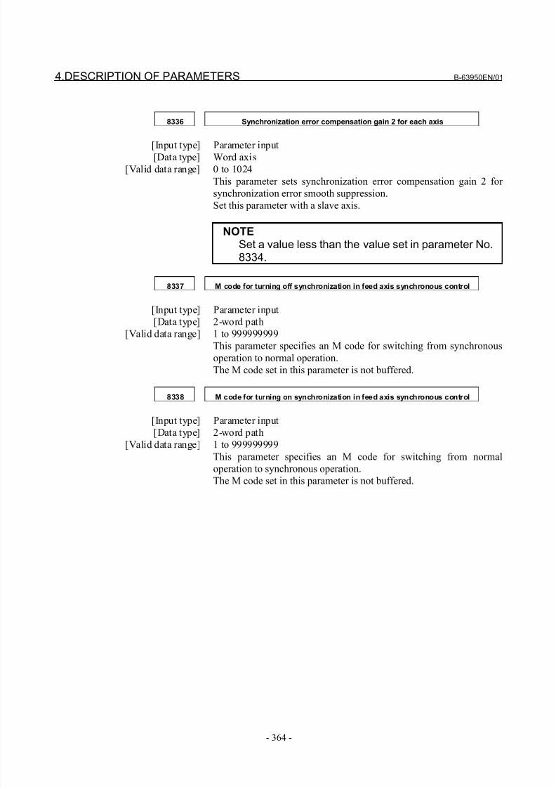
8/21/2019 30i Parameter Manual
http://slidepdf.com/reader/full/30i-parameter-manual 376/493
4.DESCRIPTION OF PARAMETERS B-63950EN/01
- 364 -
8336 Synchronization error compensation gain 2 for each axis
[Input type] Parameter input
[Data type] Word axis
[Valid data range] 0 to 1024
This parameter sets synchronization error compensation gain 2 for
synchronization error smooth suppression.
Set this parameter with a slave axis.
NOTESet a value less than the value set in parameter No.8334.
8337 M code for turning off synchronization in feed axis synchronous control
[Input type] Parameter input
[Data type] 2-word path
[Valid data range] 1 to 999999999
This parameter specifies an M code for switching from synchronous
operation to normal operation.
The M code set in this parameter is not buffered.
8338 M code for turning on synchronization in feed axis synchronous control
[Input type] Parameter input
[Data type] 2-word path
[Valid data range] 1 to 999999999
This parameter specifies an M code for switching from normal
operation to synchronous operation.
The M code set in this parameter is not buffered.
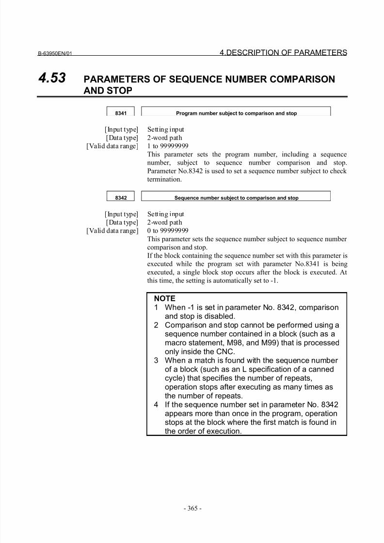
8/21/2019 30i Parameter Manual
http://slidepdf.com/reader/full/30i-parameter-manual 377/493
B-63950EN/01 4.DESCRIPTION OF PARAMETERS
- 365 -
4.53 PARAMETERS OF SEQUENCE NUMBER COMPARISON
AND STOP
8341 Program number subject to comparison and stop
[Input type] Setting input
[Data type] 2-word path
[Valid data range] 1 to 99999999
This parameter sets the program number, including a sequence
number, subject to sequence number comparison and stop.
Parameter No.8342 is used to set a sequence number subject to check
termination.
8342 Sequence number subject to comparison and stop
[Input type] Setting input
[Data type] 2-word path
[Valid data range] 0 to 99999999
This parameter sets the sequence number subject to sequence number
comparison and stop.
If the block containing the sequence number set with this parameter is
executed while the program set with parameter No.8341 is being
executed, a single block stop occurs after the block is executed. At
this time, the setting is automatically set to -1.
NOTE1 When -1 is set in parameter No. 8342, comparison
and stop is disabled.2 Comparison and stop cannot be performed using a
sequence number contained in a block (such as amacro statement, M98, and M99) that is processedonly inside the CNC.
3 When a match is found with the sequence number of a block (such as an L specification of a canned
cycle) that specifies the number of repeats,operation stops after executing as many times asthe number of repeats.
4 If the sequence number set in parameter No. 8342appears more than once in the program, operationstops at the block where the first match is found inthe order of execution.
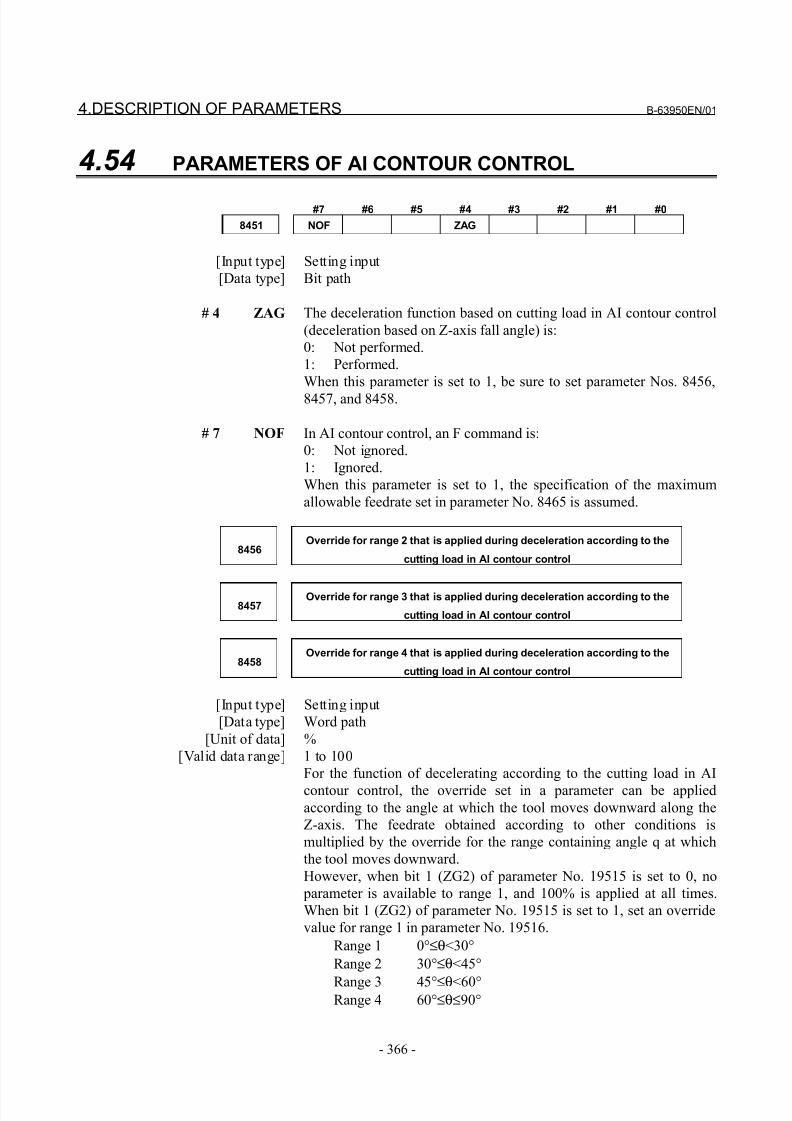
8/21/2019 30i Parameter Manual
http://slidepdf.com/reader/full/30i-parameter-manual 378/493
4.DESCRIPTION OF PARAMETERS B-63950EN/01
- 366 -
4.54 PARAMETERS OF AI CONTOUR CONTROL
#7 #6 #5 #4 #3 #2 #1 #0
8451 NOF ZAG
[Input type] Setting input
[Data type] Bit path
# 4 ZAG The deceleration function based on cutting load in AI contour control
(deceleration based on Z-axis fall angle) is:
0: Not performed.
1: Performed.
When this parameter is set to 1, be sure to set parameter Nos. 8456,
8457, and 8458.
# 7 NOF In AI contour control, an F command is:
0: Not ignored.
1: Ignored.
When this parameter is set to 1, the specification of the maximum
allowable feedrate set in parameter No. 8465 is assumed.
8456Override for range 2 that is applied during deceleration according to the
cutting load in AI contour control
8457Override for range 3 that is applied during deceleration according to the
cutting load in AI contour control
8458Override for range 4 that is applied during deceleration according to the
cutting load in AI contour control
[Input type] Setting input
[Data type] Word path
[Unit of data] %
[Valid data range] 1 to 100
For the function of decelerating according to the cutting load in AI
contour control, the override set in a parameter can be appliedaccording to the angle at which the tool moves downward along the
Z-axis. The feedrate obtained according to other conditions is
multiplied by the override for the range containing angle q at which
the tool moves downward.
However, when bit 1 (ZG2) of parameter No. 19515 is set to 0, no
parameter is available to range 1, and 100% is applied at all times.
When bit 1 (ZG2) of parameter No. 19515 is set to 1, set an override
value for range 1 in parameter No. 19516.
Range 1 0°≤θ<30°
Range 2 30°≤θ<45°
Range 3 45°≤θ<60°Range 4 60°≤θ≤90°
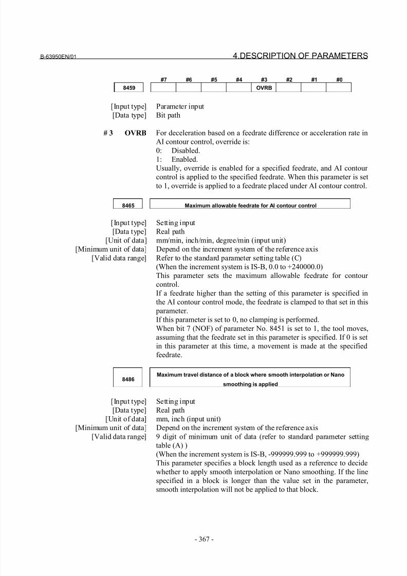
8/21/2019 30i Parameter Manual
http://slidepdf.com/reader/full/30i-parameter-manual 379/493
B-63950EN/01 4.DESCRIPTION OF PARAMETERS
- 367 -
#7 #6 #5 #4 #3 #2 #1 #0
8459 OVRB
[Input type] Parameter input
[Data type] Bit path
# 3 OVRB For deceleration based on a feedrate difference or acceleration rate in
AI contour control, override is:
0: Disabled.
1: Enabled.
Usually, override is enabled for a specified feedrate, and AI contour
control is applied to the specified feedrate. When this parameter is set
to 1, override is applied to a feedrate placed under AI contour control.
8465 Maximum allowable feedrate for AI contour control
[Input type] Setting input
[Data type] Real path
[Unit of data] mm/min, inch/min, degree/min (input unit)
[Minimum unit of data] Depend on the increment system of the reference axis
[Valid data range] Refer to the standard parameter setting table (C)
(When the increment system is IS-B, 0.0 to +240000.0)
This parameter sets the maximum allowable feedrate for contour
control.
If a feedrate higher than the setting of this parameter is specified in
the AI contour control mode, the feedrate is clamped to that set in this parameter.
If this parameter is set to 0, no clamping is performed.
When bit 7 (NOF) of parameter No. 8451 is set to 1, the tool moves,
assuming that the feedrate set in this parameter is specified. If 0 is set
in this parameter at this time, a movement is made at the specified
feedrate.
8486Maximum travel distance of a block where smooth interpolation or Nano
smoothing is applied
[Input type] Setting input[Data type] Real path
[Unit of data] mm, inch (input unit)
[Minimum unit of data] Depend on the increment system of the reference axis
[Valid data range] 9 digit of minimum unit of data (refer to standard parameter setting
table (A) )
(When the increment system is IS-B, -999999.999 to +999999.999)
This parameter specifies a block length used as a reference to decide
whether to apply smooth interpolation or Nano smoothing. If the line
specified in a block is longer than the value set in the parameter,
smooth interpolation will not be applied to that block.
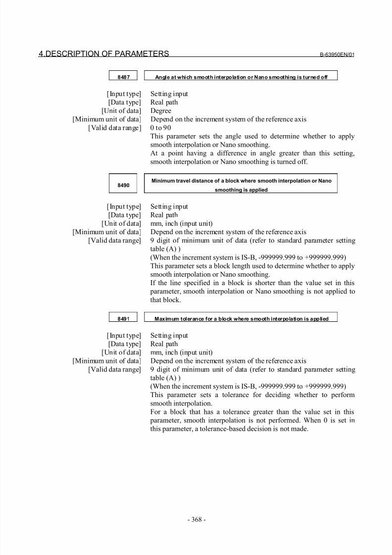
8/21/2019 30i Parameter Manual
http://slidepdf.com/reader/full/30i-parameter-manual 380/493
4.DESCRIPTION OF PARAMETERS B-63950EN/01
- 368 -
8487 Angle at which smooth interpolation or Nano smoothing is turned off
[Input type] Setting input[Data type] Real path
[Unit of data] Degree
[Minimum unit of data] Depend on the increment system of the reference axis
[Valid data range] 0 to 90
This parameter sets the angle used to determine whether to apply
smooth interpolation or Nano smoothing.
At a point having a difference in angle greater than this setting,
smooth interpolation or Nano smoothing is turned off.
8490Minimum travel distance of a block where smooth interpolation or Nano
smoothing is applied
[Input type] Setting input
[Data type] Real path
[Unit of data] mm, inch (input unit)
[Minimum unit of data] Depend on the increment system of the reference axis
[Valid data range] 9 digit of minimum unit of data (refer to standard parameter setting
table (A) )
(When the increment system is IS-B, -999999.999 to +999999.999)
This parameter sets a block length used to determine whether to apply
smooth interpolation or Nano smoothing.
If the line specified in a block is shorter than the value set in this
parameter, smooth interpolation or Nano smoothing is not applied tothat block.
8491 Maximum tolerance for a block where smooth interpolation is applied
[Input type] Setting input
[Data type] Real path
[Unit of data] mm, inch (input unit)
[Minimum unit of data] Depend on the increment system of the reference axis
[Valid data range] 9 digit of minimum unit of data (refer to standard parameter setting
table (A) )
(When the increment system is IS-B, -999999.999 to +999999.999)This parameter sets a tolerance for deciding whether to perform
smooth interpolation.
For a block that has a tolerance greater than the value set in this
parameter, smooth interpolation is not performed. When 0 is set in
this parameter, a tolerance-based decision is not made.
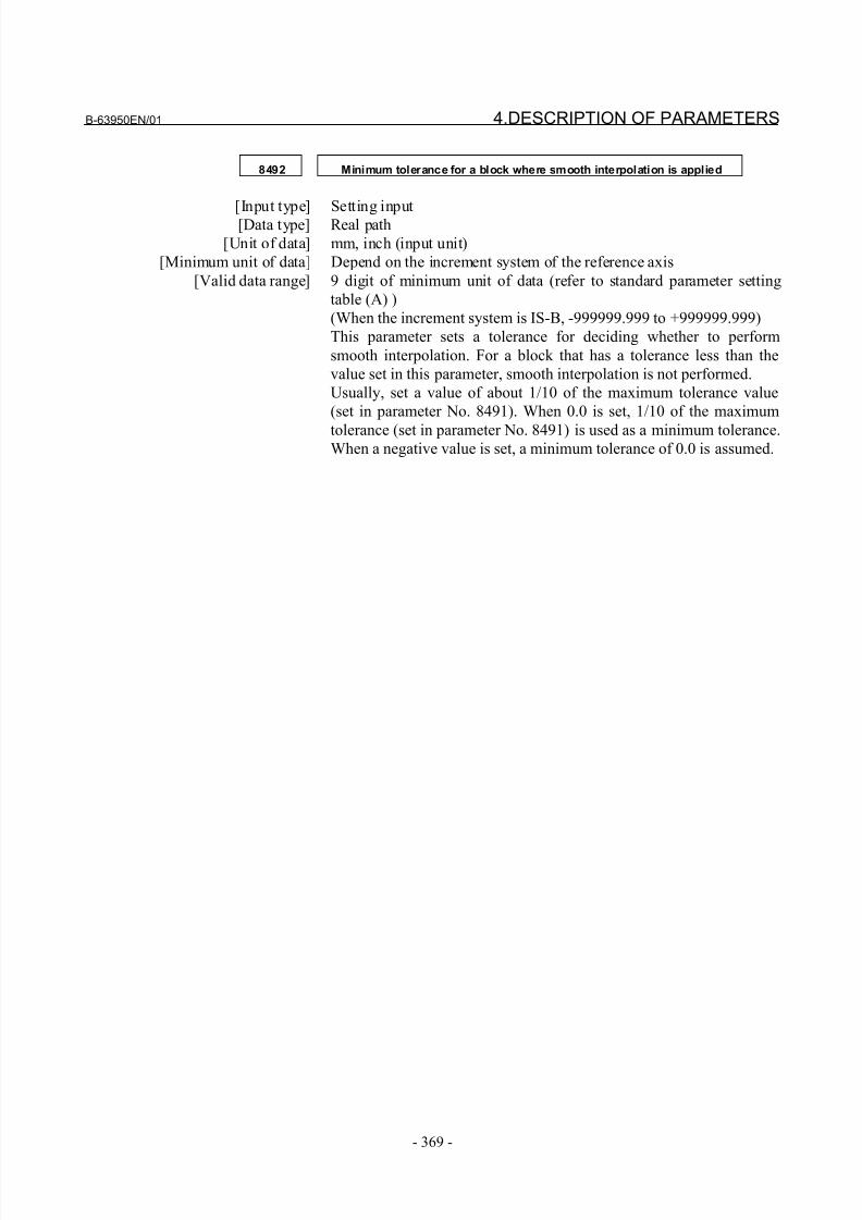
8/21/2019 30i Parameter Manual
http://slidepdf.com/reader/full/30i-parameter-manual 381/493
B-63950EN/01 4.DESCRIPTION OF PARAMETERS
- 369 -
8492 Minimum tolerance for a block where smooth interpolation is applied
[Input type] Setting input[Data type] Real path
[Unit of data] mm, inch (input unit)
[Minimum unit of data] Depend on the increment system of the reference axis
[Valid data range] 9 digit of minimum unit of data (refer to standard parameter setting
table (A) )
(When the increment system is IS-B, -999999.999 to +999999.999)
This parameter sets a tolerance for deciding whether to perform
smooth interpolation. For a block that has a tolerance less than the
value set in this parameter, smooth interpolation is not performed.
Usually, set a value of about 1/10 of the maximum tolerance value
(set in parameter No. 8491). When 0.0 is set, 1/10 of the maximum
tolerance (set in parameter No. 8491) is used as a minimum tolerance.When a negative value is set, a minimum tolerance of 0.0 is assumed.
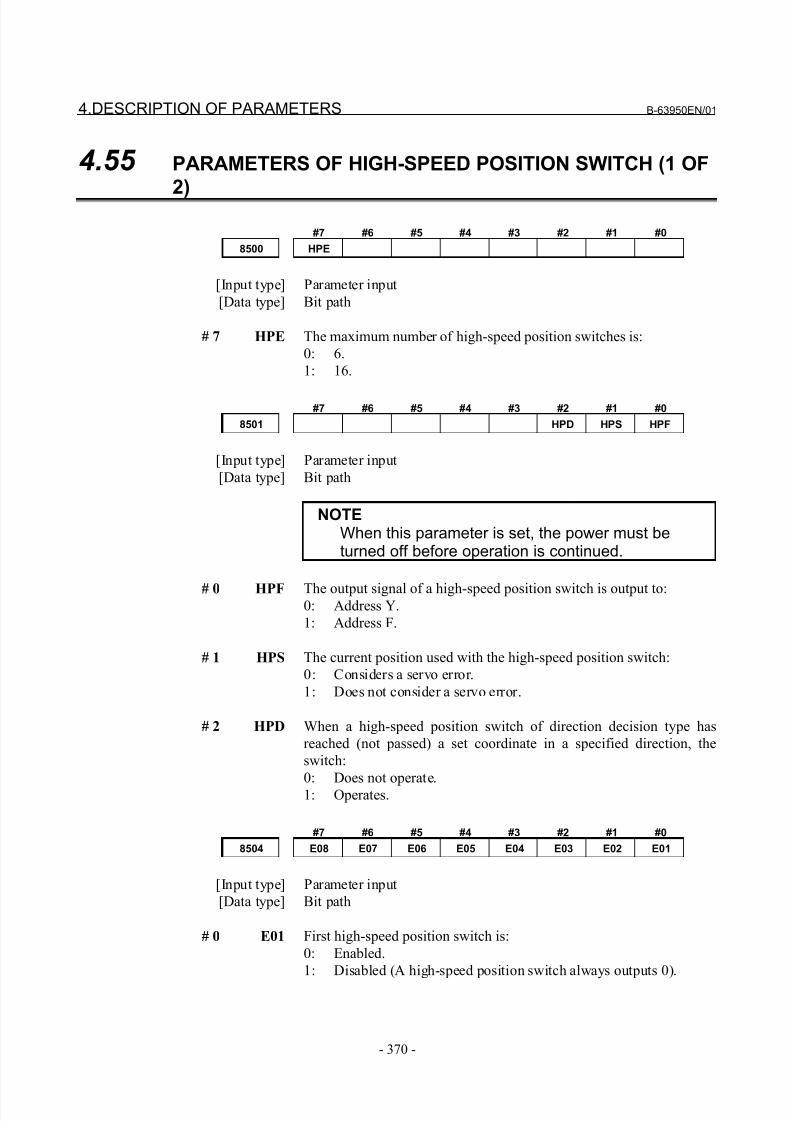
8/21/2019 30i Parameter Manual
http://slidepdf.com/reader/full/30i-parameter-manual 382/493
4.DESCRIPTION OF PARAMETERS B-63950EN/01
- 370 -
4.55 PARAMETERS OF HIGH-SPEED POSITION SWITCH (1 OF
2)
#7 #6 #5 #4 #3 #2 #1 #0
8500 HPE
[Input type] Parameter input
[Data type] Bit path
# 7 HPE The maximum number of high-speed position switches is:
0: 6.
1: 16.
#7 #6 #5 #4 #3 #2 #1 #0
8501 HPD HPS HPF
[Input type] Parameter input
[Data type] Bit path
NOTEWhen this parameter is set, the power must beturned off before operation is continued.
# 0 HPF The output signal of a high-speed position switch is output to:0: Address Y.
1: Address F.
# 1 HPS The current position used with the high-speed position switch:
0: Considers a servo error.
1: Does not consider a servo error.
# 2 HPD When a high-speed position switch of direction decision type has
reached (not passed) a set coordinate in a specified direction, the
switch:
0: Does not operate.
1: Operates.
#7 #6 #5 #4 #3 #2 #1 #0
8504 E08 E07 E06 E05 E04 E03 E02 E01
[Input type] Parameter input
[Data type] Bit path
# 0 E01 First high-speed position switch is:
0: Enabled.
1: Disabled (A high-speed position switch always outputs 0).
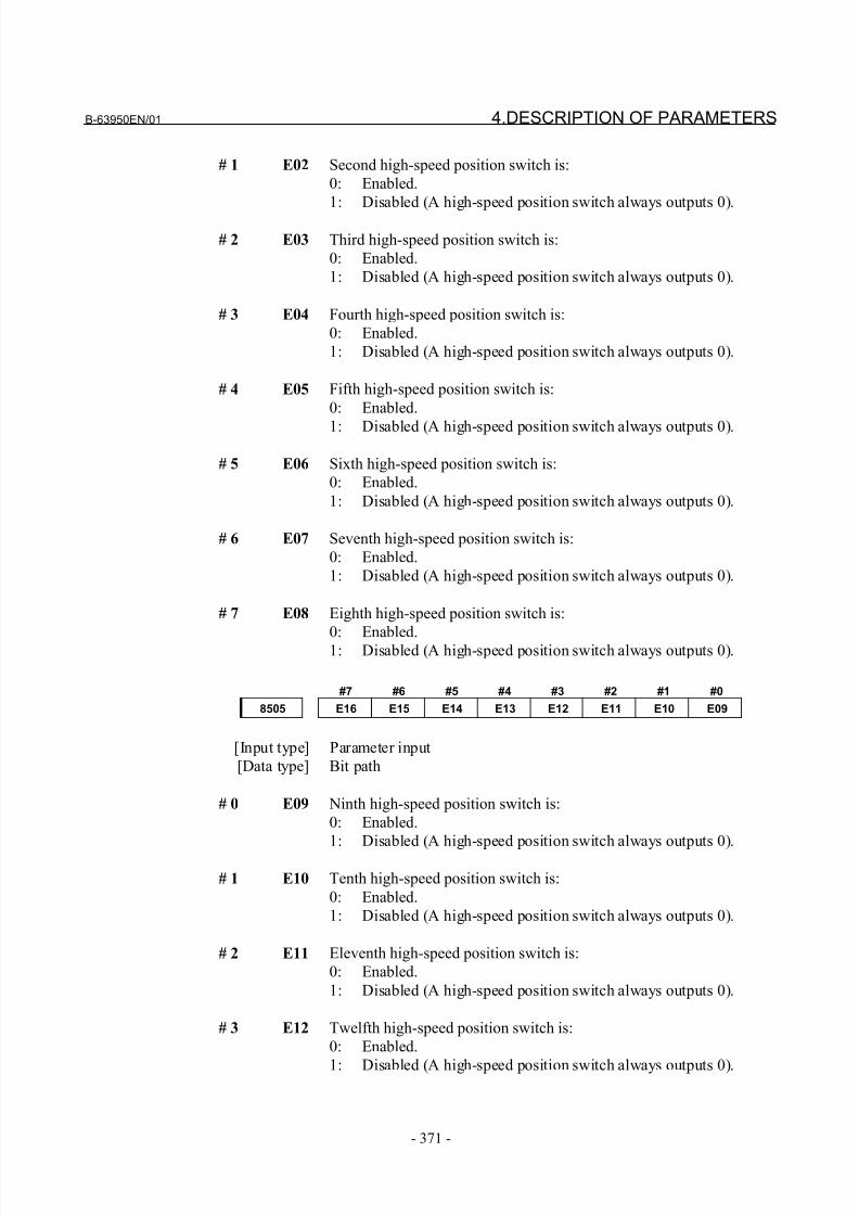
8/21/2019 30i Parameter Manual
http://slidepdf.com/reader/full/30i-parameter-manual 383/493
B-63950EN/01 4.DESCRIPTION OF PARAMETERS
- 371 -
# 1 E02 Second high-speed position switch is:
0: Enabled.
1: Disabled (A high-speed position switch always outputs 0).
# 2 E03 Third high-speed position switch is:
0: Enabled.
1: Disabled (A high-speed position switch always outputs 0).
# 3 E04 Fourth high-speed position switch is:
0: Enabled.
1: Disabled (A high-speed position switch always outputs 0).
# 4 E05 Fifth high-speed position switch is:
0: Enabled.
1: Disabled (A high-speed position switch always outputs 0).
# 5 E06 Sixth high-speed position switch is:
0: Enabled.
1: Disabled (A high-speed position switch always outputs 0).
# 6 E07 Seventh high-speed position switch is:
0: Enabled.
1: Disabled (A high-speed position switch always outputs 0).
# 7 E08 Eighth high-speed position switch is:
0: Enabled.1: Disabled (A high-speed position switch always outputs 0).
#7 #6 #5 #4 #3 #2 #1 #0
8505 E16 E15 E14 E13 E12 E11 E10 E09
[Input type] Parameter input
[Data type] Bit path
# 0 E09 Ninth high-speed position switch is:
0: Enabled.
1: Disabled (A high-speed position switch always outputs 0).
# 1 E10 Tenth high-speed position switch is:
0: Enabled.
1: Disabled (A high-speed position switch always outputs 0).
# 2 E11 Eleventh high-speed position switch is:
0: Enabled.
1: Disabled (A high-speed position switch always outputs 0).
# 3 E12 Twelfth high-speed position switch is:
0: Enabled.
1: Disabled (A high-speed position switch always outputs 0).
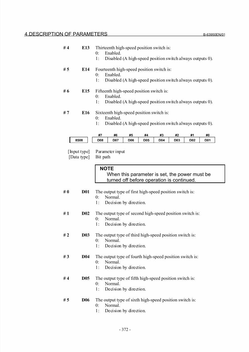
8/21/2019 30i Parameter Manual
http://slidepdf.com/reader/full/30i-parameter-manual 384/493
4.DESCRIPTION OF PARAMETERS B-63950EN/01
- 372 -
# 4 E13 Thirteenth high-speed position switch is:
0: Enabled.
1: Disabled (A high-speed position switch always outputs 0).
# 5 E14 Fourteenth high-speed position switch is:
0: Enabled.
1: Disabled (A high-speed position switch always outputs 0).
# 6 E15 Fifteenth high-speed position switch is:
0: Enabled.
1: Disabled (A high-speed position switch always outputs 0).
# 7 E16 Sixteenth high-speed position switch is:
0: Enabled.
1: Disabled (A high-speed position switch always outputs 0).
#7 #6 #5 #4 #3 #2 #1 #0
8508 D08 D07 D06 D05 D04 D03 D02 D01
[Input type] Parameter input
[Data type] Bit path
NOTEWhen this parameter is set, the power must beturned off before operation is continued.
# 0 D01 The output type of first high-speed position switch is:
0: Normal.
1: Decision by direction.
# 1 D02 The output type of second high-speed position switch is:
0: Normal.
1: Decision by direction.
# 2 D03 The output type of third high-speed position switch is:
0: Normal.
1: Decision by direction.
# 3 D04 The output type of fourth high-speed position switch is:
0: Normal.
1: Decision by direction.
# 4 D05 The output type of fifth high-speed position switch is:
0: Normal.
1: Decision by direction.
# 5 D06 The output type of sixth high-speed position switch is:
0: Normal.
1: Decision by direction.
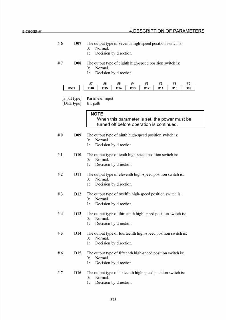
8/21/2019 30i Parameter Manual
http://slidepdf.com/reader/full/30i-parameter-manual 385/493
B-63950EN/01 4.DESCRIPTION OF PARAMETERS
- 373 -
# 6 D07 The output type of seventh high-speed position switch is:
0: Normal.
1: Decision by direction.
# 7 D08 The output type of eighth high-speed position switch is:
0: Normal.
1: Decision by direction.
#7 #6 #5 #4 #3 #2 #1 #0
8509 D16 D15 D14 D13 D12 D11 D10 D09
[Input type] Parameter input
[Data type] Bit path
NOTEWhen this parameter is set, the power must beturned off before operation is continued.
# 0 D09 The output type of ninth high-speed position switch is:
0: Normal.
1: Decision by direction.
# 1 D10 The output type of tenth high-speed position switch is:
0: Normal.
1: Decision by direction.
# 2 D11 The output type of eleventh high-speed position switch is:
0: Normal.
1: Decision by direction.
# 3 D12 The output type of twelfth high-speed position switch is:
0: Normal.
1: Decision by direction.
# 4 D13 The output type of thirteenth high-speed position switch is:
0: Normal.
1: Decision by direction.
# 5 D14 The output type of fourteenth high-speed position switch is:
0: Normal.
1: Decision by direction.
# 6 D15 The output type of fifteenth high-speed position switch is:
0: Normal.
1: Decision by direction.
# 7 D16 The output type of sixteenth high-speed position switch is:
0: Normal.
1: Decision by direction.
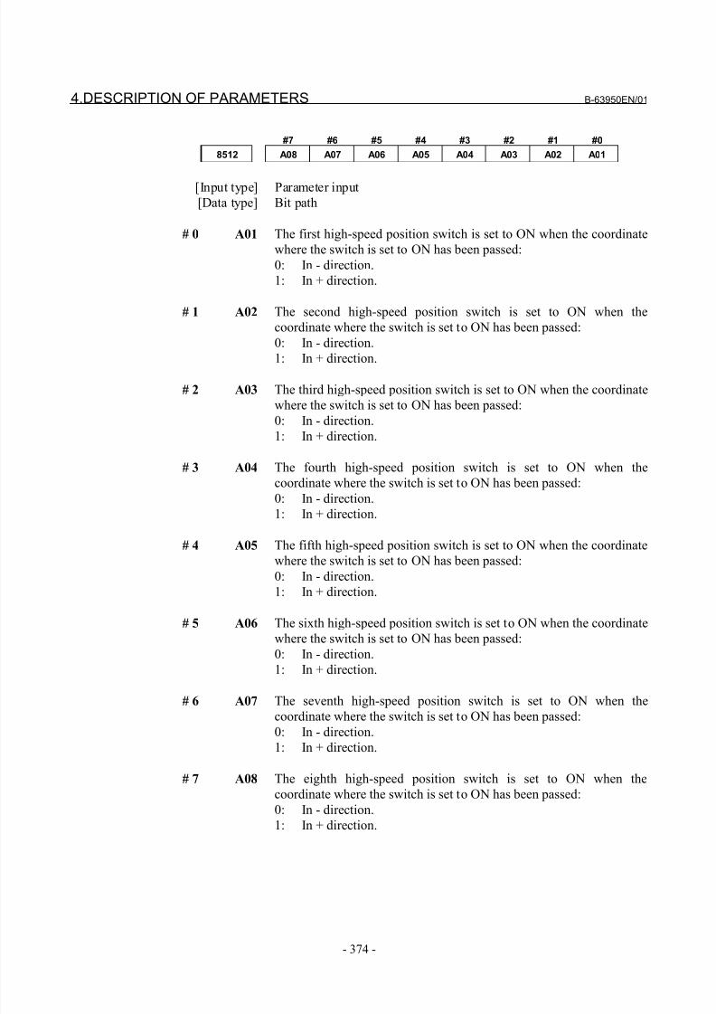
8/21/2019 30i Parameter Manual
http://slidepdf.com/reader/full/30i-parameter-manual 386/493
4.DESCRIPTION OF PARAMETERS B-63950EN/01
- 374 -
#7 #6 #5 #4 #3 #2 #1 #0
8512 A08 A07 A06 A05 A04 A03 A02 A01
[Input type] Parameter input
[Data type] Bit path
# 0 A01 The first high-speed position switch is set to ON when the coordinate
where the switch is set to ON has been passed:
0: In - direction.
1: In + direction.
# 1 A02 The second high-speed position switch is set to ON when the
coordinate where the switch is set to ON has been passed:
0: In - direction.
1: In + direction.
# 2 A03 The third high-speed position switch is set to ON when the coordinate
where the switch is set to ON has been passed:
0: In - direction.
1: In + direction.
# 3 A04 The fourth high-speed position switch is set to ON when the
coordinate where the switch is set to ON has been passed:
0: In - direction.
1: In + direction.
# 4 A05 The fifth high-speed position switch is set to ON when the coordinate
where the switch is set to ON has been passed:
0: In - direction.
1: In + direction.
# 5 A06 The sixth high-speed position switch is set to ON when the coordinate
where the switch is set to ON has been passed:
0: In - direction.
1: In + direction.
# 6 A07 The seventh high-speed position switch is set to ON when the
coordinate where the switch is set to ON has been passed:
0: In - direction.
1: In + direction.
# 7 A08 The eighth high-speed position switch is set to ON when the
coordinate where the switch is set to ON has been passed:
0: In - direction.
1: In + direction.
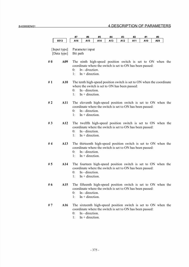
8/21/2019 30i Parameter Manual
http://slidepdf.com/reader/full/30i-parameter-manual 387/493
B-63950EN/01 4.DESCRIPTION OF PARAMETERS
- 375 -
#7 #6 #5 #4 #3 #2 #1 #0
8513 A16 A15 A14 A13 A12 A11 A10 A09
[Input type] Parameter input
[Data type] Bit path
# 0 A09 The ninth high-speed position switch is set to ON when the
coordinate where the switch is set to ON has been passed:
0: In - direction.
1: In + direction.
# 1 A10 The tenth high-speed position switch is set to ON when the coordinate
where the switch is set to ON has been passed:
0: In - direction.
1: In + direction.
# 2 A11 The eleventh high-speed position switch is set to ON when the
coordinate where the switch is set to ON has been passed:
0: In - direction.
1: In + direction.
# 3 A12 The twelfth high-speed position switch is set to ON when the
coordinate where the switch is set to ON has been passed:
0: In - direction.
1: In + direction.
# 4 A13 The thirteenth high-speed position switch is set to ON when the
coordinate where the switch is set to ON has been passed:
0: In - direction.
1: In + direction.
# 5 A14 The fourteen high-speed position switch is set to ON when the
coordinate where the switch is set to ON has been passed:
0: In - direction.
1: In + direction.
# 6 A15 The fifteenth high-speed position switch is set to ON when the
coordinate where the switch is set to ON has been passed:
0: In - direction.
1: In + direction.
# 7 A16 The sixteenth high-speed position switch is set to ON when the
coordinate where the switch is set to ON has been passed:
0: In - direction.
1: In + direction.

8/21/2019 30i Parameter Manual
http://slidepdf.com/reader/full/30i-parameter-manual 388/493
4.DESCRIPTION OF PARAMETERS B-63950EN/01
- 376 -
#7 #6 #5 #4 #3 #2 #1 #0
8516 B08 B07 B06 B05 B04 B03 B02 B01
[Input type] Parameter input
[Data type] Bit path
# 0 B01 The first high-speed position switch is set to OFF when the coordinate
where the switch is set to OFF has been passed:
0: In - direction.
1: In + direction.
# 1 B02 The second high-speed position switch is set to OFF when the
coordinate where the switch is set to OFF has been passed:
0: In - direction.
1: In + direction.
# 2 B03 The third high-speed position switch is set to OFF when the
coordinate where the switch is set to OFF has been passed:
0: In - direction.
1: In + direction.
# 3 B04 The fourth high-speed position switch is set to OFF when the
coordinate where the switch is set to OFF has been passed:
0: In - direction.
1: In + direction.
# 4 B05 The fifth high-speed position switch is set to OFF when the
coordinate where the switch is set to OFF has been passed:
0: In - direction.
1: In + direction.
# 5 B06 The sixth high-speed position switch is set to OFF when the
coordinate where the switch is set to OFF has been passed:
0: In - direction.
1: In + direction.
# 6 B07 The seventh high-speed position switch is set to OFF when the
coordinate where the switch is set to OFF has been passed:
0: In - direction.
1: In + direction.
# 7 B08 The eighth high-speed position switch is set to OFF when the
coordinate where the switch is set to OFF has been passed:
0: In - direction.
1: In + direction.
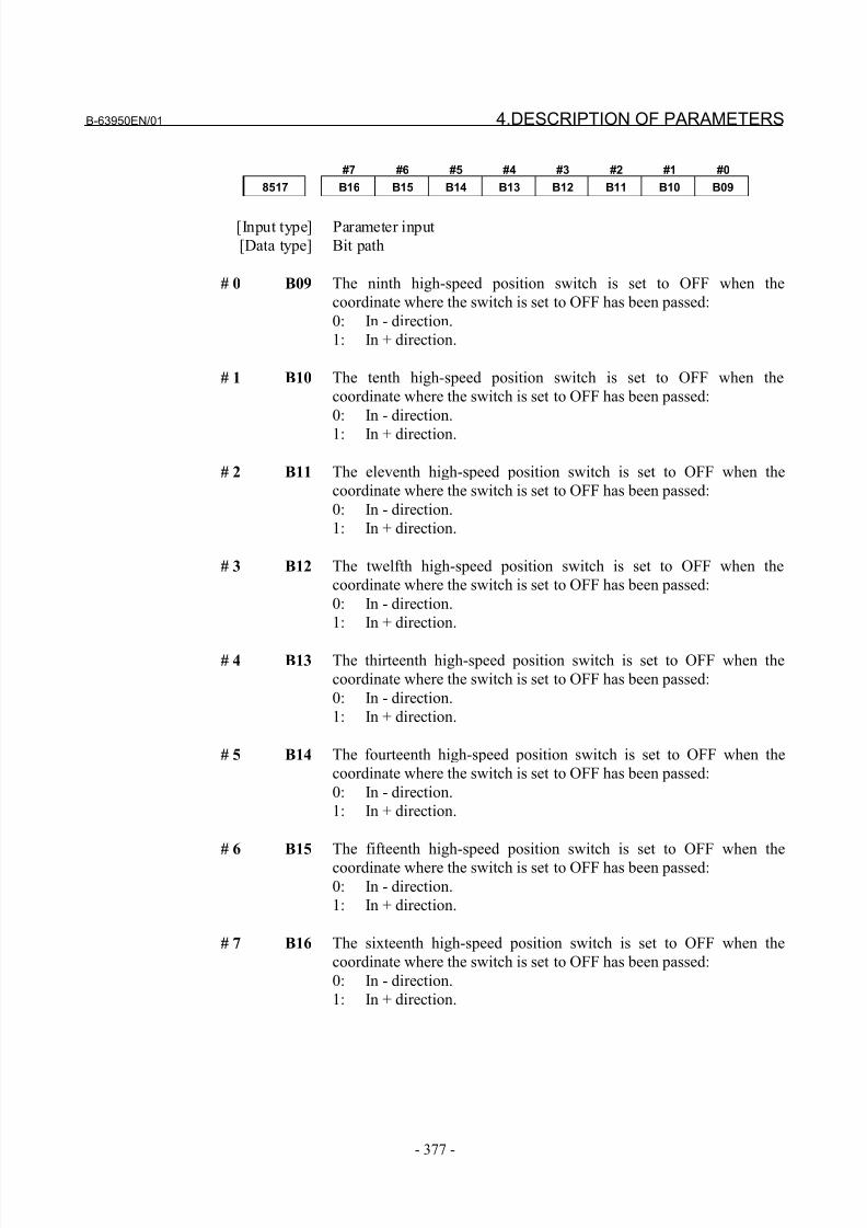
8/21/2019 30i Parameter Manual
http://slidepdf.com/reader/full/30i-parameter-manual 389/493
B-63950EN/01 4.DESCRIPTION OF PARAMETERS
- 377 -
#7 #6 #5 #4 #3 #2 #1 #0
8517 B16 B15 B14 B13 B12 B11 B10 B09
[Input type] Parameter input
[Data type] Bit path
# 0 B09 The ninth high-speed position switch is set to OFF when the
coordinate where the switch is set to OFF has been passed:
0: In - direction.
1: In + direction.
# 1 B10 The tenth high-speed position switch is set to OFF when the
coordinate where the switch is set to OFF has been passed:
0: In - direction.
1: In + direction.
# 2 B11 The eleventh high-speed position switch is set to OFF when the
coordinate where the switch is set to OFF has been passed:
0: In - direction.
1: In + direction.
# 3 B12 The twelfth high-speed position switch is set to OFF when the
coordinate where the switch is set to OFF has been passed:
0: In - direction.
1: In + direction.
# 4 B13 The thirteenth high-speed position switch is set to OFF when the
coordinate where the switch is set to OFF has been passed:
0: In - direction.
1: In + direction.
# 5 B14 The fourteenth high-speed position switch is set to OFF when the
coordinate where the switch is set to OFF has been passed:
0: In - direction.
1: In + direction.
# 6 B15 The fifteenth high-speed position switch is set to OFF when the
coordinate where the switch is set to OFF has been passed:
0: In - direction.
1: In + direction.
# 7 B16 The sixteenth high-speed position switch is set to OFF when the
coordinate where the switch is set to OFF has been passed:
0: In - direction.
1: In + direction.
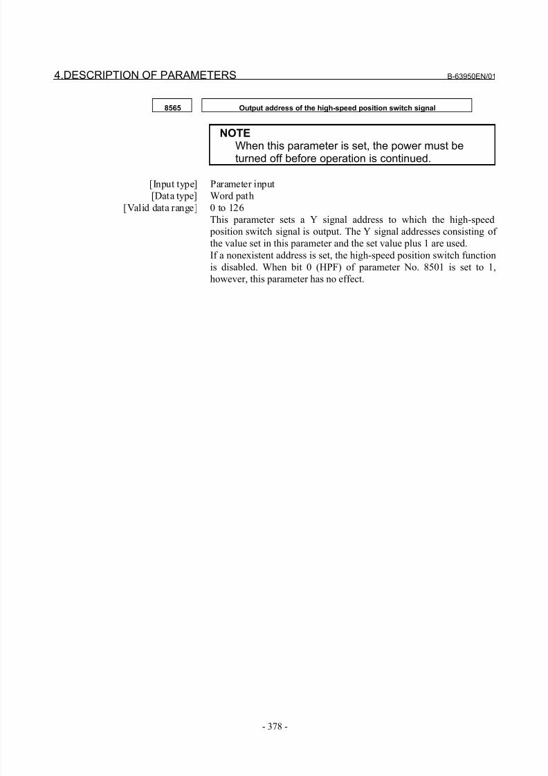
8/21/2019 30i Parameter Manual
http://slidepdf.com/reader/full/30i-parameter-manual 390/493
4.DESCRIPTION OF PARAMETERS B-63950EN/01
- 378 -
8565 Output address of the high-speed position switch signal
NOTEWhen this parameter is set, the power must beturned off before operation is continued.
[Input type] Parameter input
[Data type] Word path
[Valid data range] 0 to 126
This parameter sets a Y signal address to which the high-speed
position switch signal is output. The Y signal addresses consisting of
the value set in this parameter and the set value plus 1 are used.
If a nonexistent address is set, the high-speed position switch function
is disabled. When bit 0 (HPF) of parameter No. 8501 is set to 1,however, this parameter has no effect.
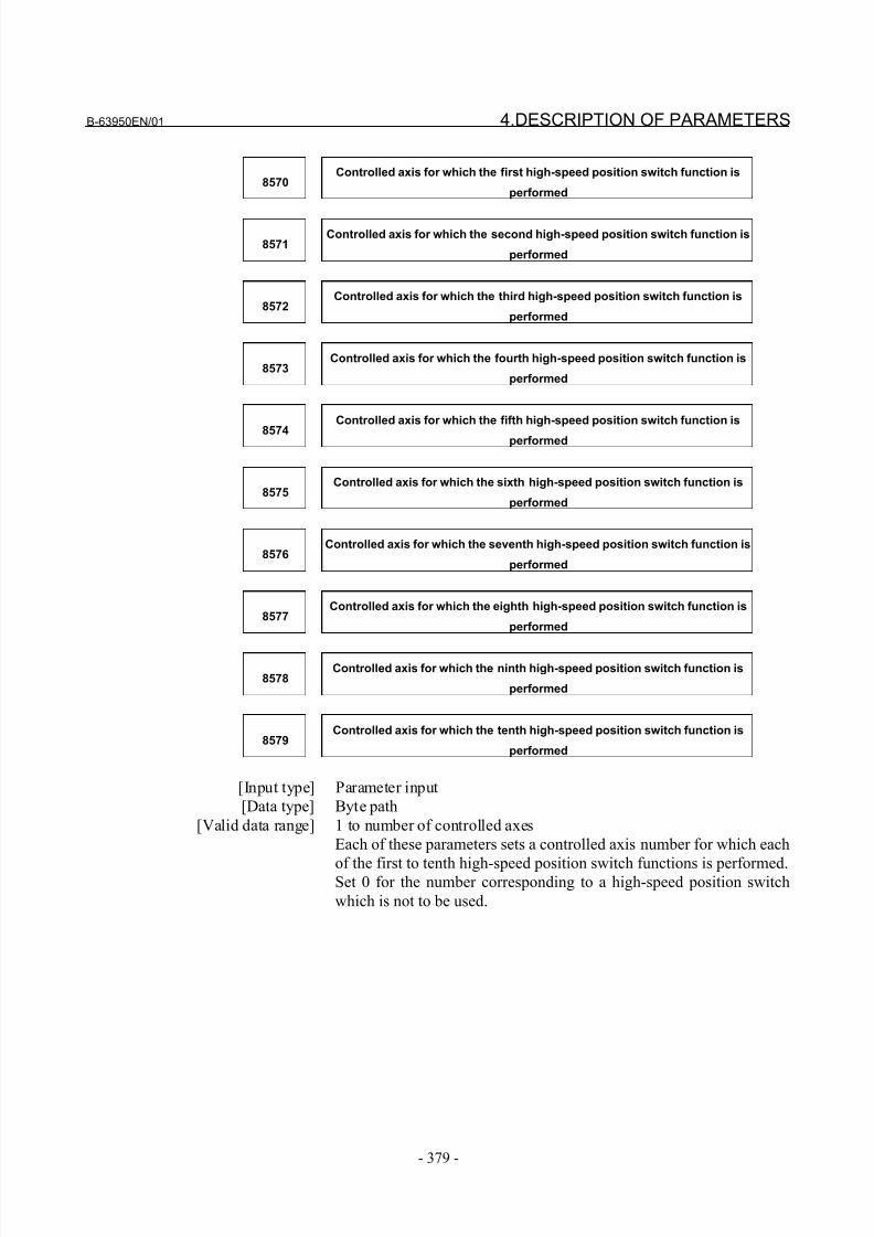
8/21/2019 30i Parameter Manual
http://slidepdf.com/reader/full/30i-parameter-manual 391/493
B-63950EN/01 4.DESCRIPTION OF PARAMETERS
- 379 -
8570Controlled axis for which the first high-speed position switch function is
performed
8571Controlled axis for which the second high-speed position switch function is
performed
8572Controlled axis for which the third high-speed position switch function is
performed
8573Controlled axis for which the fourth high-speed position switch function is
performed
8574
Controlled axis for which the fifth high-speed position switch function is
performed
8575Controlled axis for which the sixth high-speed position switch function is
performed
8576Controlled axis for which the seventh high-speed position switch function is
performed
8577Controlled axis for which the eighth high-speed position switch function is
performed
8578Controlled axis for which the ninth high-speed position switch function is
performed
8579Controlled axis for which the tenth high-speed position switch function is
performed
[Input type] Parameter input
[Data type] Byte path
[Valid data range] 1 to number of controlled axes
Each of these parameters sets a controlled axis number for which each
of the first to tenth high-speed position switch functions is performed.Set 0 for the number corresponding to a high-speed position switch
which is not to be used.
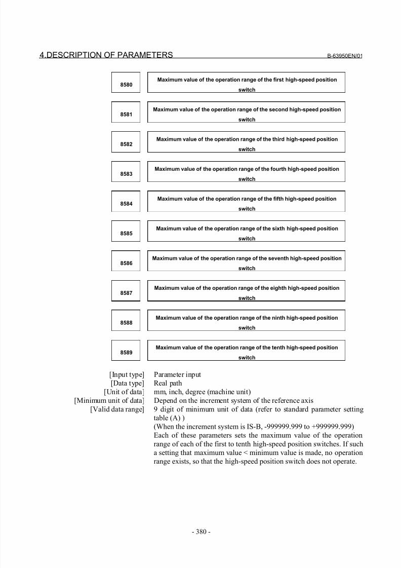
8/21/2019 30i Parameter Manual
http://slidepdf.com/reader/full/30i-parameter-manual 392/493
4.DESCRIPTION OF PARAMETERS B-63950EN/01
- 380 -
8580Maximum value of the operation range of the first high-speed position
switch
8581Maximum value of the operation range of the second high-speed position
switch
8582Maximum value of the operation range of the third high-speed position
switch
8583Maximum value of the operation range of the fourth high-speed position
switch
8584Maximum value of the operation range of the fifth high-speed position
switch
8585Maximum value of the operation range of the sixth high-speed position
switch
8586Maximum value of the operation range of the seventh high-speed position
switch
8587Maximum value of the operation range of the eighth high-speed position
switch
8588Maximum value of the operation range of the ninth high-speed position
switch
8589Maximum value of the operation range of the tenth high-speed position
switch
[Input type] Parameter input
[Data type] Real path
[Unit of data] mm, inch, degree (machine unit)
[Minimum unit of data] Depend on the increment system of the reference axis[Valid data range] 9 digit of minimum unit of data (refer to standard parameter setting
table (A) )
(When the increment system is IS-B, -999999.999 to +999999.999)
Each of these parameters sets the maximum value of the operation
range of each of the first to tenth high-speed position switches. If such
a setting that maximum value < minimum value is made, no operation
range exists, so that the high-speed position switch does not operate.
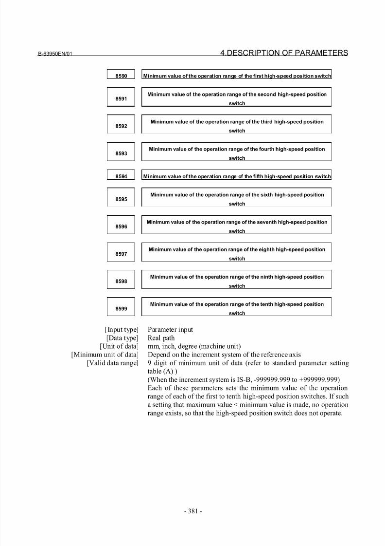
8/21/2019 30i Parameter Manual
http://slidepdf.com/reader/full/30i-parameter-manual 393/493
B-63950EN/01 4.DESCRIPTION OF PARAMETERS
- 381 -
8590 Minimum value of the operation range of the first high-speed position switch
8591 Minimum value of the operation range of the second high-speed positionswitch
8592Minimum value of the operation range of the third high-speed position
switch
8593Minimum value of the operation range of the fourth high-speed position
switch
8594 Minimum value of the operation range of the fifth high-speed position switch
8595Minimum value of the operation range of the sixth high-speed position
switch
8596Minimum value of the operation range of the seventh high-speed position
switch
8597Minimum value of the operation range of the eighth high-speed position
switch
8598Minimum value of the operation range of the ninth high-speed position
switch
8599Minimum value of the operation range of the tenth high-speed position
switch
[Input type] Parameter input
[Data type] Real path
[Unit of data] mm, inch, degree (machine unit)
[Minimum unit of data] Depend on the increment system of the reference axis
[Valid data range] 9 digit of minimum unit of data (refer to standard parameter setting
table (A) )
(When the increment system is IS-B, -999999.999 to +999999.999)Each of these parameters sets the minimum value of the operation
range of each of the first to tenth high-speed position switches. If such
a setting that maximum value < minimum value is made, no operation
range exists, so that the high-speed position switch does not operate.
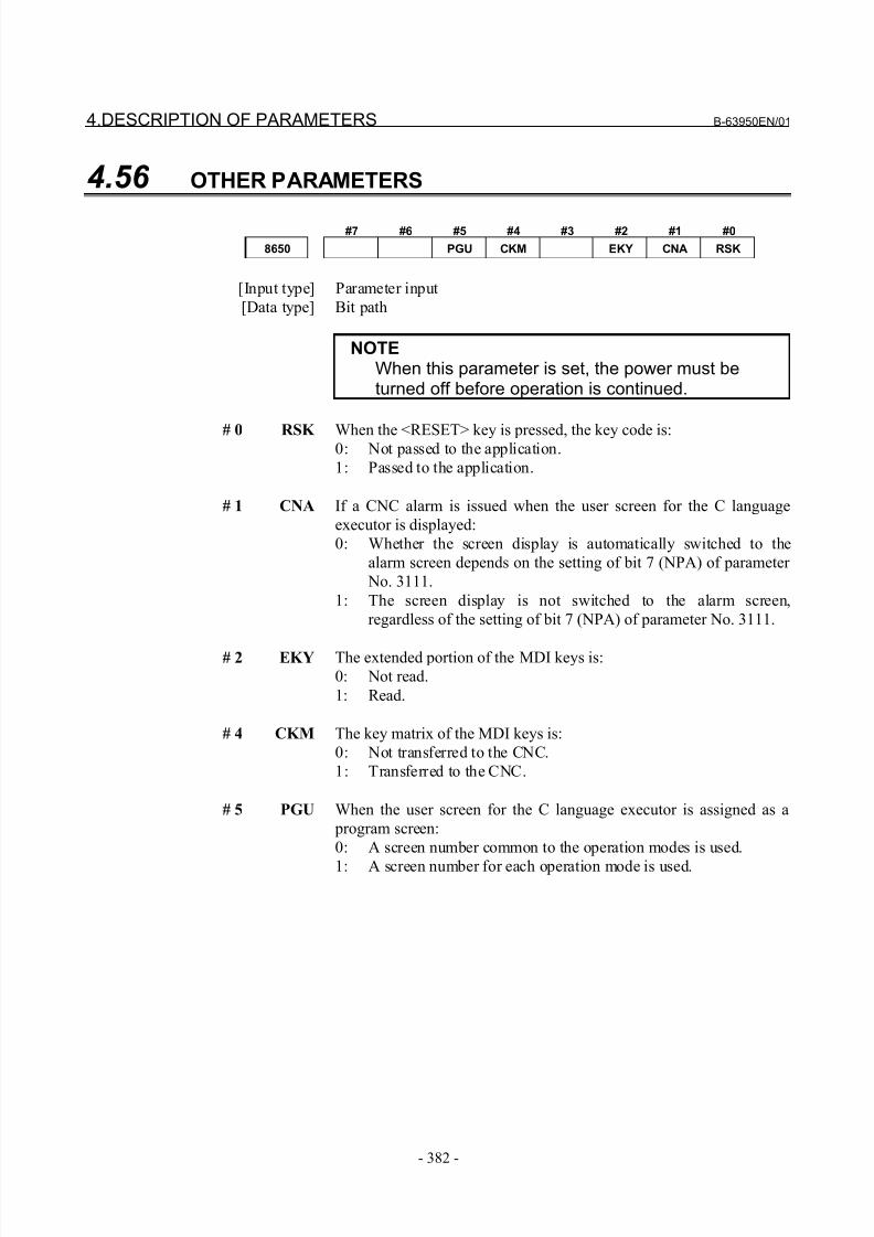
8/21/2019 30i Parameter Manual
http://slidepdf.com/reader/full/30i-parameter-manual 394/493
4.DESCRIPTION OF PARAMETERS B-63950EN/01
- 382 -
4.56 OTHER PARAMETERS
#7 #6 #5 #4 #3 #2 #1 #0
8650 PGU CKM EKY CNA RSK
[Input type] Parameter input
[Data type] Bit path
NOTEWhen this parameter is set, the power must beturned off before operation is continued.
# 0 RSK When the <RESET> key is pressed, the key code is:0: Not passed to the application.
1: Passed to the application.
# 1 CNA If a CNC alarm is issued when the user screen for the C language
executor is displayed:
0: Whether the screen display is automatically switched to the
alarm screen depends on the setting of bit 7 (NPA) of parameter
No. 3111.
1: The screen display is not switched to the alarm screen,
regardless of the setting of bit 7 (NPA) of parameter No. 3111.
# 2 EKY The extended portion of the MDI keys is:
0: Not read.
1: Read.
# 4 CKM The key matrix of the MDI keys is:
0: Not transferred to the CNC.
1: Transferred to the CNC.
# 5 PGU When the user screen for the C language executor is assigned as a
program screen:
0: A screen number common to the operation modes is used.
1: A screen number for each operation mode is used.
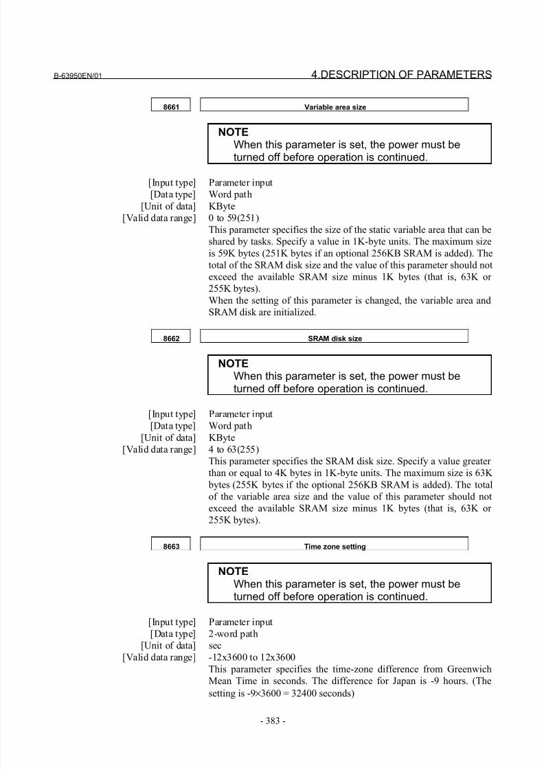
8/21/2019 30i Parameter Manual
http://slidepdf.com/reader/full/30i-parameter-manual 395/493
B-63950EN/01 4.DESCRIPTION OF PARAMETERS
- 383 -
8661 Variable area size
NOTEWhen this parameter is set, the power must beturned off before operation is continued.
[Input type] Parameter input
[Data type] Word path
[Unit of data] KByte
[Valid data range] 0 to 59(251)
This parameter specifies the size of the static variable area that can be
shared by tasks. Specify a value in 1K-byte units. The maximum size
is 59K bytes (251K bytes if an optional 256KB SRAM is added). The
total of the SRAM disk size and the value of this parameter should notexceed the available SRAM size minus 1K bytes (that is, 63K or
255K bytes).
When the setting of this parameter is changed, the variable area and
SRAM disk are initialized.
8662 SRAM disk size
NOTEWhen this parameter is set, the power must beturned off before operation is continued.
[Input type] Parameter input
[Data type] Word path
[Unit of data] KByte
[Valid data range] 4 to 63(255)
This parameter specifies the SRAM disk size. Specify a value greater
than or equal to 4K bytes in 1K-byte units. The maximum size is 63K
bytes (255K bytes if the optional 256KB SRAM is added). The total
of the variable area size and the value of this parameter should not
exceed the available SRAM size minus 1K bytes (that is, 63K or
255K bytes).
8663 Time zone setting
NOTEWhen this parameter is set, the power must beturned off before operation is continued.
[Input type] Parameter input
[Data type] 2-word path
[Unit of data] sec
[Valid data range] -12x3600 to 12x3600
This parameter specifies the time-zone difference from Greenwich
Mean Time in seconds. The difference for Japan is -9 hours. (The
setting is -9×3600 = 32400 seconds)
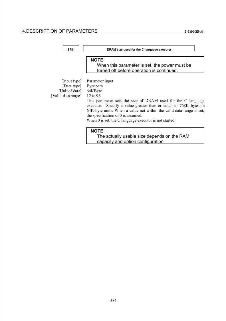
8/21/2019 30i Parameter Manual
http://slidepdf.com/reader/full/30i-parameter-manual 396/493
4.DESCRIPTION OF PARAMETERS B-63950EN/01
- 384 -
8781 DRAM size used for the C language executor
NOTEWhen this parameter is set, the power must beturned off before operation is continued.
[Input type] Parameter input
[Data type] Byte path
[Unit of data] 64KByte
[Valid data range] 12 to 96
This parameter sets the size of DRAM used for the C language
executor. Specify a value greater than or equal to 768K bytes in
64K-byte units. When a value not within the valid data range is set,the specification of 0 is assumed.
When 0 is set, the C language executor is not started.
NOTEThe actually usable size depends on the RAMcapacity and option configuration.
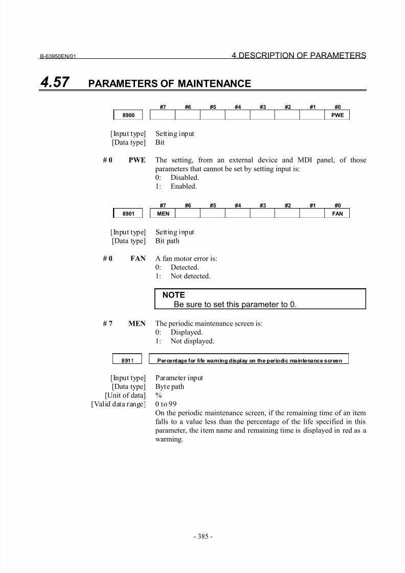
8/21/2019 30i Parameter Manual
http://slidepdf.com/reader/full/30i-parameter-manual 397/493
B-63950EN/01 4.DESCRIPTION OF PARAMETERS
- 385 -
4.57 PARAMETERS OF MAINTENANCE
#7 #6 #5 #4 #3 #2 #1 #0
8900 PWE
[Input type] Setting input
[Data type] Bit
# 0 PWE The setting, from an external device and MDI panel, of those
parameters that cannot be set by setting input is:
0: Disabled.
1: Enabled.
#7 #6 #5 #4 #3 #2 #1 #0
8901 MEN FAN
[Input type] Setting input
[Data type] Bit path
# 0 FAN A fan motor error is:
0: Detected.
1: Not detected.
NOTEBe sure to set this parameter to 0.
# 7 MEN The periodic maintenance screen is:
0: Displayed.
1: Not displayed.
8911 Percentage for life warning display on the periodic maintenance screen
[Input type] Parameter input
[Data type] Byte path
[Unit of data] %
[Valid data range] 0 to 99On the periodic maintenance screen, if the remaining time of an item
falls to a value less than the percentage of the life specified in this
parameter, the item name and remaining time is displayed in red as a
warming.
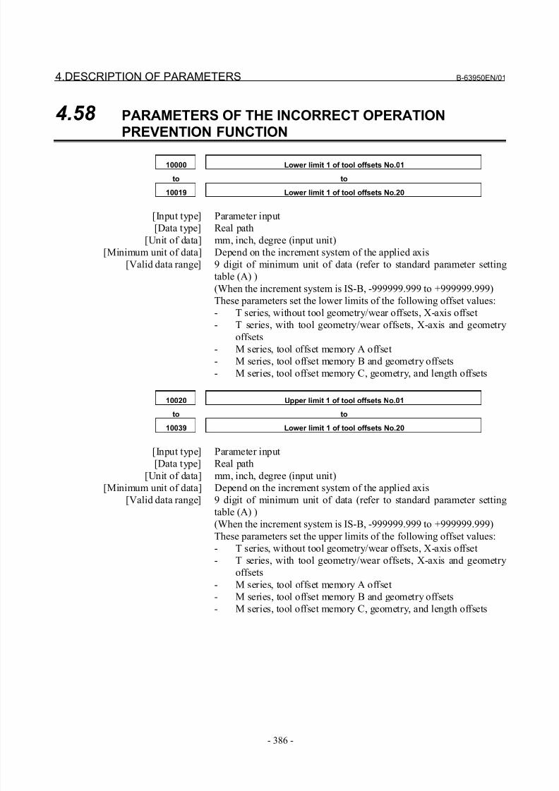
8/21/2019 30i Parameter Manual
http://slidepdf.com/reader/full/30i-parameter-manual 398/493
4.DESCRIPTION OF PARAMETERS B-63950EN/01
- 386 -
4.58 PARAMETERS OF THE INCORRECT OPERATION
PREVENTION FUNCTION
10000 Lower limit 1 of tool offsets No.01
to to
10019 Lower limit 1 of tool offsets No.20
[Input type] Parameter input
[Data type] Real path
[Unit of data] mm, inch, degree (input unit)
[Minimum unit of data] Depend on the increment system of the applied axis
[Valid data range] 9 digit of minimum unit of data (refer to standard parameter setting
table (A) )(When the increment system is IS-B, -999999.999 to +999999.999)
These parameters set the lower limits of the following offset values:
- T series, without tool geometry/wear offsets, X-axis offset
- T series, with tool geometry/wear offsets, X-axis and geometry
offsets
- M series, tool offset memory A offset
- M series, tool offset memory B and geometry offsets
- M series, tool offset memory C, geometry, and length offsets
10020 Upper limit 1 of tool offsets No.01
to to
10039 Lower limit 1 of tool offsets No.20
[Input type] Parameter input
[Data type] Real path
[Unit of data] mm, inch, degree (input unit)
[Minimum unit of data] Depend on the increment system of the applied axis
[Valid data range] 9 digit of minimum unit of data (refer to standard parameter setting
table (A) )
(When the increment system is IS-B, -999999.999 to +999999.999)
These parameters set the upper limits of the following offset values:
- T series, without tool geometry/wear offsets, X-axis offset
- T series, with tool geometry/wear offsets, X-axis and geometry
offsets
- M series, tool offset memory A offset
- M series, tool offset memory B and geometry offsets
- M series, tool offset memory C, geometry, and length offsets
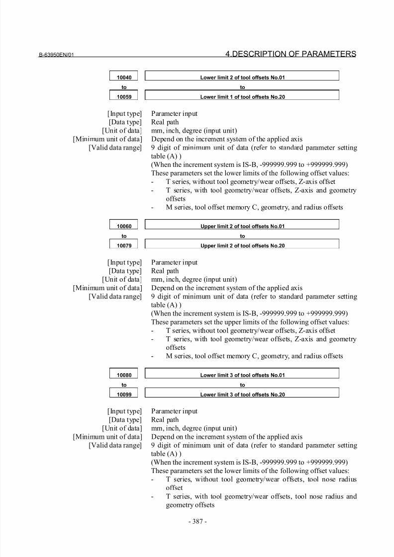
8/21/2019 30i Parameter Manual
http://slidepdf.com/reader/full/30i-parameter-manual 399/493
B-63950EN/01 4.DESCRIPTION OF PARAMETERS
- 387 -
10040 Lower limit 2 of tool offsets No.01
to to
10059 Lower limit 1 of tool offsets No.20
[Input type] Parameter input
[Data type] Real path
[Unit of data] mm, inch, degree (input unit)
[Minimum unit of data] Depend on the increment system of the applied axis
[Valid data range] 9 digit of minimum unit of data (refer to standard parameter setting
table (A) )
(When the increment system is IS-B, -999999.999 to +999999.999)
These parameters set the lower limits of the following offset values:
- T series, without tool geometry/wear offsets, Z-axis offset
- T series, with tool geometry/wear offsets, Z-axis and geometry
offsets
- M series, tool offset memory C, geometry, and radius offsets
10060 Upper limit 2 of tool offsets No.01
to to
10079 Upper limit 2 of tool offsets No.20
[Input type] Parameter input
[Data type] Real path
[Unit of data] mm, inch, degree (input unit)
[Minimum unit of data] Depend on the increment system of the applied axis
[Valid data range] 9 digit of minimum unit of data (refer to standard parameter setting
table (A) )
(When the increment system is IS-B, -999999.999 to +999999.999)
These parameters set the upper limits of the following offset values:
- T series, without tool geometry/wear offsets, Z-axis offset
- T series, with tool geometry/wear offsets, Z-axis and geometry
offsets
- M series, tool offset memory C, geometry, and radius offsets
10080 Lower limit 3 of tool offsets No.01
to to
10099 Lower limit 3 of tool offsets No.20
[Input type] Parameter input
[Data type] Real path
[Unit of data] mm, inch, degree (input unit)
[Minimum unit of data] Depend on the increment system of the applied axis
[Valid data range] 9 digit of minimum unit of data (refer to standard parameter setting
table (A) )
(When the increment system is IS-B, -999999.999 to +999999.999)
These parameters set the lower limits of the following offset values:
- T series, without tool geometry/wear offsets, tool nose radius
offset- T series, with tool geometry/wear offsets, tool nose radius and
geometry offsets
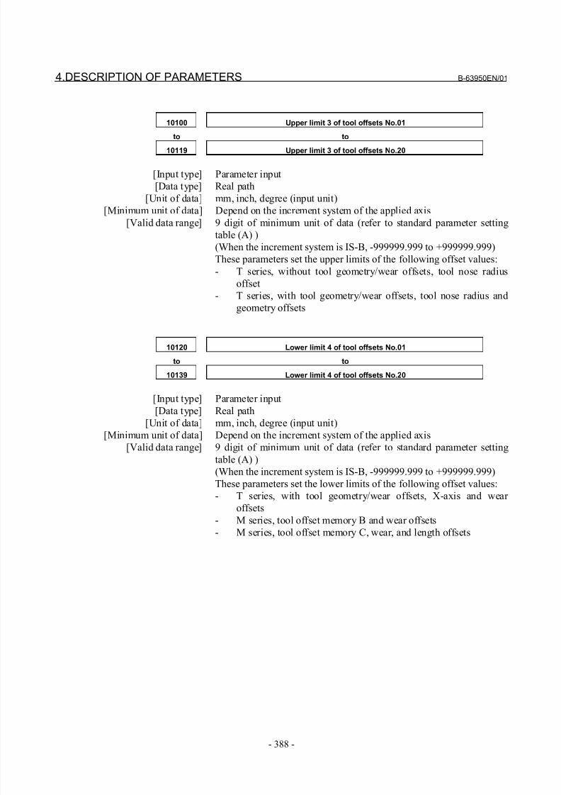
8/21/2019 30i Parameter Manual
http://slidepdf.com/reader/full/30i-parameter-manual 400/493
4.DESCRIPTION OF PARAMETERS B-63950EN/01
- 388 -
10100 Upper limit 3 of tool offsets No.01
to to10119 Upper limit 3 of tool offsets No.20
[Input type] Parameter input
[Data type] Real path
[Unit of data] mm, inch, degree (input unit)
[Minimum unit of data] Depend on the increment system of the applied axis
[Valid data range] 9 digit of minimum unit of data (refer to standard parameter setting
table (A) )
(When the increment system is IS-B, -999999.999 to +999999.999)
These parameters set the upper limits of the following offset values:
- T series, without tool geometry/wear offsets, tool nose radius
offset
- T series, with tool geometry/wear offsets, tool nose radius and
geometry offsets
10120 Lower limit 4 of tool offsets No.01
to to
10139 Lower limit 4 of tool offsets No.20
[Input type] Parameter input
[Data type] Real path
[Unit of data] mm, inch, degree (input unit)
[Minimum unit of data] Depend on the increment system of the applied axis
[Valid data range] 9 digit of minimum unit of data (refer to standard parameter setting
table (A) )
(When the increment system is IS-B, -999999.999 to +999999.999)
These parameters set the lower limits of the following offset values:
- T series, with tool geometry/wear offsets, X-axis and wear
offsets
- M series, tool offset memory B and wear offsets
- M series, tool offset memory C, wear, and length offsets
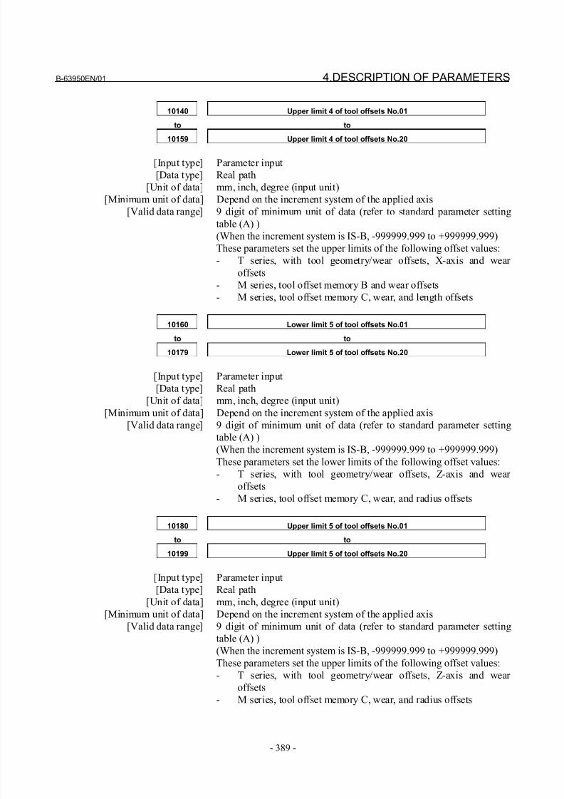
8/21/2019 30i Parameter Manual
http://slidepdf.com/reader/full/30i-parameter-manual 401/493
B-63950EN/01 4.DESCRIPTION OF PARAMETERS
- 389 -
10140 Upper limit 4 of tool offsets No.01
to to
10159 Upper limit 4 of tool offsets No.20
[Input type] Parameter input
[Data type] Real path
[Unit of data] mm, inch, degree (input unit)
[Minimum unit of data] Depend on the increment system of the applied axis
[Valid data range] 9 digit of minimum unit of data (refer to standard parameter setting
table (A) )
(When the increment system is IS-B, -999999.999 to +999999.999)
These parameters set the upper limits of the following offset values:
- T series, with tool geometry/wear offsets, X-axis and wear
offsets
- M series, tool offset memory B and wear offsets
- M series, tool offset memory C, wear, and length offsets
10160 Lower limit 5 of tool offsets No.01
to to
10179 Lower limit 5 of tool offsets No.20
[Input type] Parameter input
[Data type] Real path
[Unit of data] mm, inch, degree (input unit)
[Minimum unit of data] Depend on the increment system of the applied axis
[Valid data range] 9 digit of minimum unit of data (refer to standard parameter setting
table (A) )
(When the increment system is IS-B, -999999.999 to +999999.999)
These parameters set the lower limits of the following offset values:
- T series, with tool geometry/wear offsets, Z-axis and wear
offsets
- M series, tool offset memory C, wear, and radius offsets
10180 Upper limit 5 of tool offsets No.01
to to
10199 Upper limit 5 of tool offsets No.20
[Input type] Parameter input
[Data type] Real path
[Unit of data] mm, inch, degree (input unit)
[Minimum unit of data] Depend on the increment system of the applied axis
[Valid data range] 9 digit of minimum unit of data (refer to standard parameter setting
table (A) )
(When the increment system is IS-B, -999999.999 to +999999.999)
These parameters set the upper limits of the following offset values:
- T series, with tool geometry/wear offsets, Z-axis and wear
offsets
- M series, tool offset memory C, wear, and radius offsets
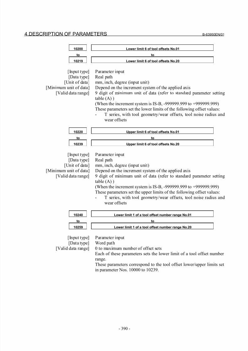
8/21/2019 30i Parameter Manual
http://slidepdf.com/reader/full/30i-parameter-manual 402/493
4.DESCRIPTION OF PARAMETERS B-63950EN/01
- 390 -
10200 Lower limit 6 of tool offsets No.01
to to
10219 Lower limit 6 of tool offsets No.20
[Input type] Parameter input
[Data type] Real path
[Unit of data] mm, inch, degree (input unit)
[Minimum unit of data] Depend on the increment system of the applied axis
[Valid data range] 9 digit of minimum unit of data (refer to standard parameter setting
table (A) )
(When the increment system is IS-B, -999999.999 to +999999.999)
These parameters set the lower limits of the following offset values:
- T series, with tool geometry/wear offsets, tool noise radius and
wear offsets
10220 Upper limit 6 of tool offsets No.01
to to
10239 Upper limit 6 of tool offsets No.20
[Input type] Parameter input
[Data type] Real path
[Unit of data] mm, inch, degree (input unit)
[Minimum unit of data] Depend on the increment system of the applied axis
[Valid data range] 9 digit of minimum unit of data (refer to standard parameter setting
table (A) )
(When the increment system is IS-B, -999999.999 to +999999.999)
These parameters set the upper limits of the following offset values:
- T series, with tool geometry/wear offsets, tool noise radius and
wear offsets
10240 Lower limit 1 of a tool offset number range No.01
to to
10259 Lower limit 1 of a tool offset number range No.20
[Input type] Parameter input
[Data type] Word path
[Valid data range] 0 to maximum number of offset sets
Each of these parameters sets the lower limit of a tool offset number
range.
These parameters correspond to the tool offset lower/upper limits set
in parameter Nos. 10000 to 10239.
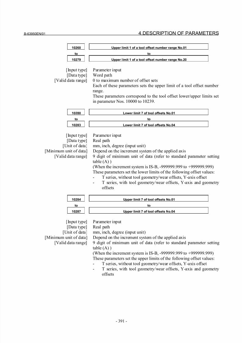
8/21/2019 30i Parameter Manual
http://slidepdf.com/reader/full/30i-parameter-manual 403/493
B-63950EN/01 4.DESCRIPTION OF PARAMETERS
- 391 -
10260 Upper limit 1 of a tool offset number range No.01
to to
10279 Upper limit 1 of a tool offset number range No.20
[Input type] Parameter input
[Data type] Word path
[Valid data range] 0 to maximum number of offset sets
Each of these parameters sets the upper limit of a tool offset number
range.
These parameters correspond to the tool offset lower/upper limits set
in parameter Nos. 10000 to 10239.
10280 Lower limit 7 of tool offsets No.01
to to10283 Lower limit 7 of tool offsets No.04
[Input type] Parameter input
[Data type] Real path
[Unit of data] mm, inch, degree (input unit)
[Minimum unit of data] Depend on the increment system of the applied axis
[Valid data range] 9 digit of minimum unit of data (refer to standard parameter setting
table (A) )
(When the increment system is IS-B, -999999.999 to +999999.999)
These parameters set the lower limits of the following offset values:
- T series, without tool geometry/wear offsets, Y-axis offset
- T series, with tool geometry/wear offsets, Y-axis and geometry
offsets
10284 Upper limit 7 of tool offsets No.01
to to
10287 Upper limit 7 of tool offsets No.04
[Input type] Parameter input
[Data type] Real path
[Unit of data] mm, inch, degree (input unit)
[Minimum unit of data] Depend on the increment system of the applied axis
[Valid data range] 9 digit of minimum unit of data (refer to standard parameter setting
table (A) )
(When the increment system is IS-B, -999999.999 to +999999.999)
These parameters set the upper limits of the following offset values:
- T series, without tool geometry/wear offsets, Y-axis offset
- T series, with tool geometry/wear offsets, Y-axis and geometry
offsets
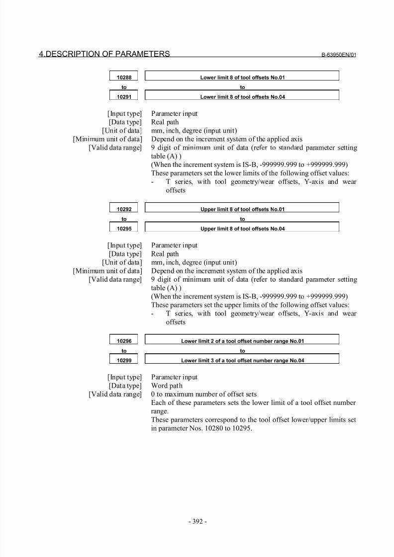
8/21/2019 30i Parameter Manual
http://slidepdf.com/reader/full/30i-parameter-manual 404/493
4.DESCRIPTION OF PARAMETERS B-63950EN/01
- 392 -
10288 Lower limit 8 of tool offsets No.01
to to
10291 Lower limit 8 of tool offsets No.04
[Input type] Parameter input
[Data type] Real path
[Unit of data] mm, inch, degree (input unit)
[Minimum unit of data] Depend on the increment system of the applied axis
[Valid data range] 9 digit of minimum unit of data (refer to standard parameter setting
table (A) )
(When the increment system is IS-B, -999999.999 to +999999.999)
These parameters set the lower limits of the following offset values:
- T series, with tool geometry/wear offsets, Y-axis and wear
offsets
10292 Upper limit 8 of tool offsets No.01
to to
10295 Upper limit 8 of tool offsets No.04
[Input type] Parameter input
[Data type] Real path
[Unit of data] mm, inch, degree (input unit)
[Minimum unit of data] Depend on the increment system of the applied axis
[Valid data range] 9 digit of minimum unit of data (refer to standard parameter setting
table (A) )
(When the increment system is IS-B, -999999.999 to +999999.999)
These parameters set the upper limits of the following offset values:
- T series, with tool geometry/wear offsets, Y-axis and wear
offsets
10296 Lower limit 2 of a tool offset number range No.01
to to
10299 Lower limit 3 of a tool offset number range No.04
[Input type] Parameter input
[Data type] Word path
[Valid data range] 0 to maximum number of offset sets
Each of these parameters sets the lower limit of a tool offset number
range.
These parameters correspond to the tool offset lower/upper limits set
in parameter Nos. 10280 to 10295.
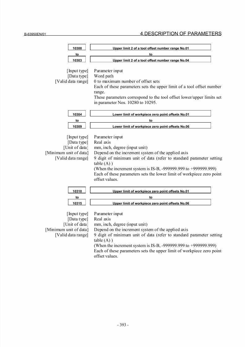
8/21/2019 30i Parameter Manual
http://slidepdf.com/reader/full/30i-parameter-manual 405/493
B-63950EN/01 4.DESCRIPTION OF PARAMETERS
- 393 -
10300 Upper limit 2 of a tool offset number range No.01
to to
10303 Upper limit 2 of a tool offset number range No.04
[Input type] Parameter input
[Data type] Word path
[Valid data range] 0 to maximum number of offset sets
Each of these parameters sets the upper limit of a tool offset number
range.
These parameters correspond to the tool offset lower/upper limits set
in parameter Nos. 10280 to 10295.
10304 Lower limit of workpiece zero point offsets No.01
to to10309 Lower limit of workpiece zero point offsets No.06
[Input type] Parameter input
[Data type] Real axis
[Unit of data] mm, inch, degree (input unit)
[Minimum unit of data] Depend on the increment system of the applied axis
[Valid data range] 9 digit of minimum unit of data (refer to standard parameter setting
table (A) )
(When the increment system is IS-B, -999999.999 to +999999.999)
Each of these parameters sets the lower limit of workpiece zero point
offset values.
10310 Upper limit of workpiece zero point offsets No.01
to to
10315 Upper limit of workpiece zero point offsets No.06
[Input type] Parameter input
[Data type] Real axis
[Unit of data] mm, inch, degree (input unit)
[Minimum unit of data] Depend on the increment system of the applied axis
[Valid data range] 9 digit of minimum unit of data (refer to standard parameter setting
table (A) )
(When the increment system is IS-B, -999999.999 to +999999.999)
Each of these parameters sets the upper limit of workpiece zero point
offset values.
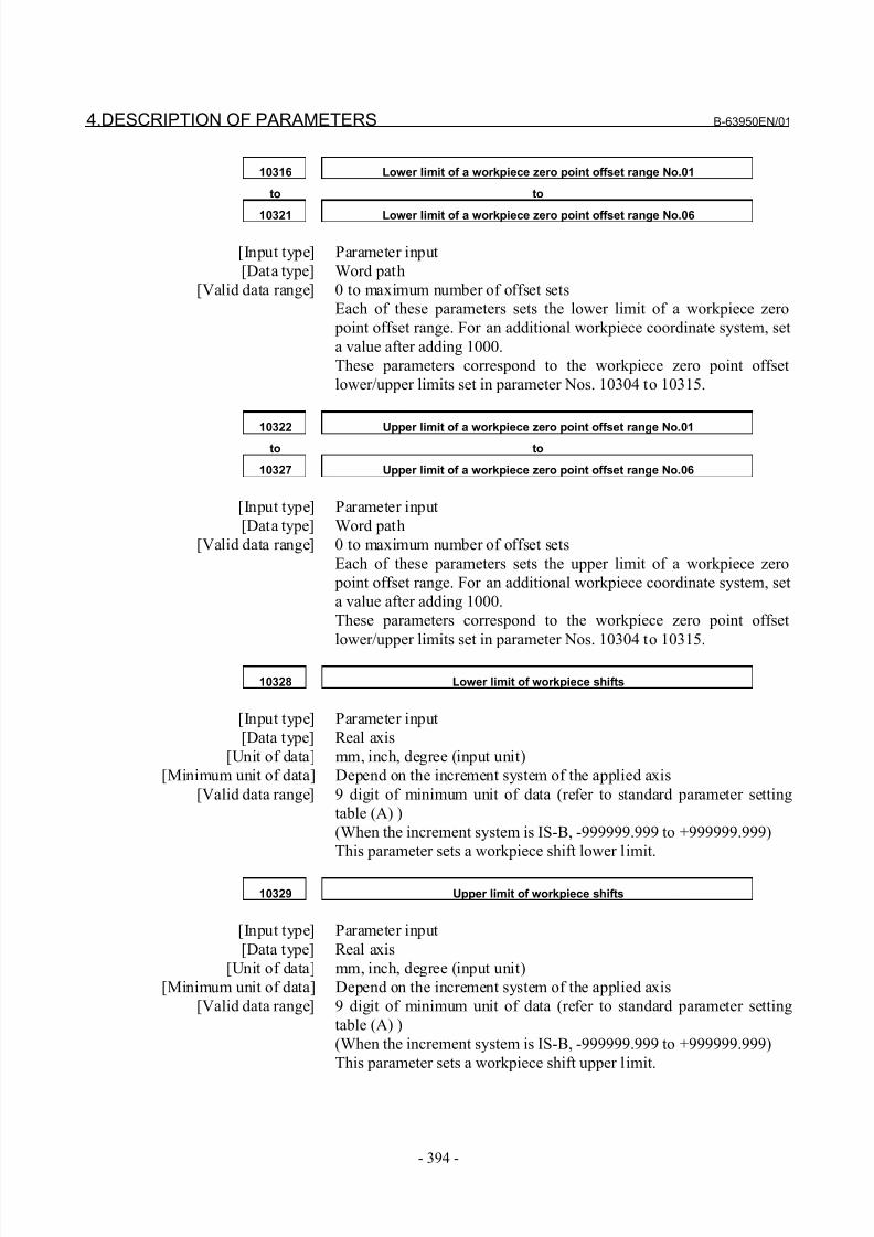
8/21/2019 30i Parameter Manual
http://slidepdf.com/reader/full/30i-parameter-manual 406/493
4.DESCRIPTION OF PARAMETERS B-63950EN/01
- 394 -
10316 Lower limit of a workpiece zero point offset range No.01
to to
10321 Lower limit of a workpiece zero point offset range No.06
[Input type] Parameter input
[Data type] Word path
[Valid data range] 0 to maximum number of offset sets
Each of these parameters sets the lower limit of a workpiece zero
point offset range. For an additional workpiece coordinate system, set
a value after adding 1000.
These parameters correspond to the workpiece zero point offset
lower/upper limits set in parameter Nos. 10304 to 10315.
10322 Upper limit of a workpiece zero point offset range No.01to to
10327 Upper limit of a workpiece zero point offset range No.06
[Input type] Parameter input
[Data type] Word path
[Valid data range] 0 to maximum number of offset sets
Each of these parameters sets the upper limit of a workpiece zero
point offset range. For an additional workpiece coordinate system, set
a value after adding 1000.
These parameters correspond to the workpiece zero point offset
lower/upper limits set in parameter Nos. 10304 to 10315.
10328 Lower limit of workpiece shifts
[Input type] Parameter input
[Data type] Real axis
[Unit of data] mm, inch, degree (input unit)
[Minimum unit of data] Depend on the increment system of the applied axis
[Valid data range] 9 digit of minimum unit of data (refer to standard parameter setting
table (A) )
(When the increment system is IS-B, -999999.999 to +999999.999)
This parameter sets a workpiece shift lower limit.
10329 Upper limit of workpiece shifts
[Input type] Parameter input
[Data type] Real axis
[Unit of data] mm, inch, degree (input unit)
[Minimum unit of data] Depend on the increment system of the applied axis
[Valid data range] 9 digit of minimum unit of data (refer to standard parameter setting
table (A) )
(When the increment system is IS-B, -999999.999 to +999999.999)
This parameter sets a workpiece shift upper limit.
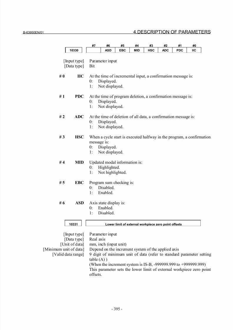
8/21/2019 30i Parameter Manual
http://slidepdf.com/reader/full/30i-parameter-manual 407/493
B-63950EN/01 4.DESCRIPTION OF PARAMETERS
- 395 -
#7 #6 #5 #4 #3 #2 #1 #0
10330 ASD EBC MID HSC ADC PDC IIC
[Input type] Parameter input
[Data type] Bit
# 0 IIC At the time of incremental input, a confirmation message is:
0: Displayed.
1: Not displayed.
# 1 PDC At the time of program deletion, a confirmation message is:
0: Displayed.
1: Not displayed.
# 2 ADC At the time of deletion of all data, a confirmation message is:0: Displayed.
1: Not displayed.
# 3 HSC When a cycle start is executed halfway in the program, a confirmation
message is:
0: Displayed.
1: Not displayed.
# 4 MID Updated modal information is:
0: Highlighted.
1: Not highlighted.
# 5 EBC Program sum checking is:
0: Disabled.
1: Enabled.
# 6 ASD Axis state display is:
0: Enabled.
1: Disabled.
10331 Lower limit of external workpiece zero point offsets
[Input type] Parameter input
[Data type] Real axis
[Unit of data] mm, inch (input unit)
[Minimum unit of data] Depend on the increment system of the applied axis
[Valid data range] 9 digit of minimum unit of data (refer to standard parameter setting
table (A) )
(When the increment system is IS-B, -999999.999 to +999999.999)
This parameter sets the lower limit of external workpiece zero point
offsets.
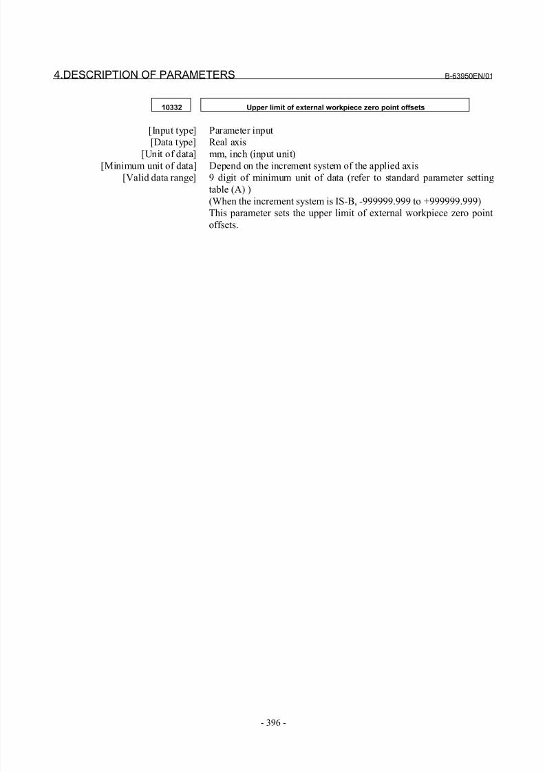
8/21/2019 30i Parameter Manual
http://slidepdf.com/reader/full/30i-parameter-manual 408/493
4.DESCRIPTION OF PARAMETERS B-63950EN/01
- 396 -
10332 Upper limit of external workpiece zero point offsets
[Input type] Parameter input[Data type] Real axis
[Unit of data] mm, inch (input unit)
[Minimum unit of data] Depend on the increment system of the applied axis
[Valid data range] 9 digit of minimum unit of data (refer to standard parameter setting
table (A) )
(When the increment system is IS-B, -999999.999 to +999999.999)
This parameter sets the upper limit of external workpiece zero point
offsets.
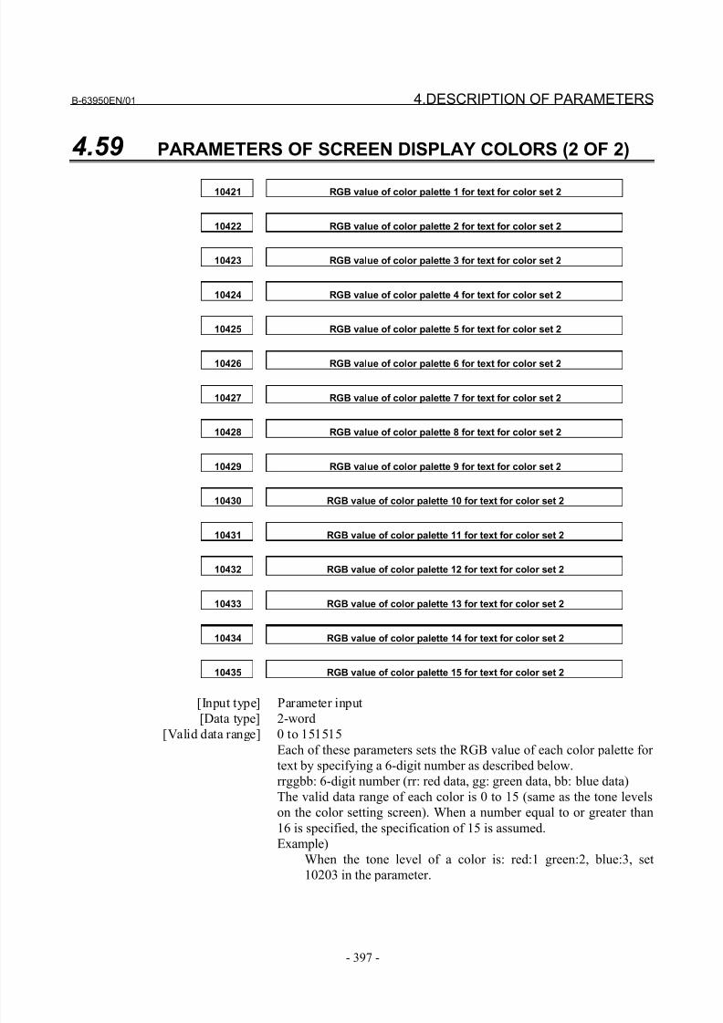
8/21/2019 30i Parameter Manual
http://slidepdf.com/reader/full/30i-parameter-manual 409/493
B-63950EN/01 4.DESCRIPTION OF PARAMETERS
- 397 -
4.59 PARAMETERS OF SCREEN DISPLAY COLORS (2 OF 2)
10421 RGB value of color palette 1 for text for color set 2
10422 RGB value of color palette 2 for text for color set 2
10423 RGB value of color palette 3 for text for color set 2
10424 RGB value of color palette 4 for text for color set 2
10425 RGB value of color palette 5 for text for color set 2
10426 RGB value of color palette 6 for text for color set 2
10427 RGB value of color palette 7 for text for color set 2
10428 RGB value of color palette 8 for text for color set 2
10429 RGB value of color palette 9 for text for color set 2
10430 RGB value of color palette 10 for text for color set 2
10431 RGB value of color palette 11 for text for color set 2
10432 RGB value of color palette 12 for text for color set 2
10433 RGB value of color palette 13 for text for color set 2
10434 RGB value of color palette 14 for text for color set 2
10435 RGB value of color palette 15 for text for color set 2
[Input type] Parameter input
[Data type] 2-word[Valid data range] 0 to 151515
Each of these parameters sets the RGB value of each color palette for
text by specifying a 6-digit number as described below.
rrggbb: 6-digit number (rr: red data, gg: green data, bb: blue data)
The valid data range of each color is 0 to 15 (same as the tone levels
on the color setting screen). When a number equal to or greater than
16 is specified, the specification of 15 is assumed.
Example)
When the tone level of a color is: red:1 green:2, blue:3, set
10203 in the parameter.
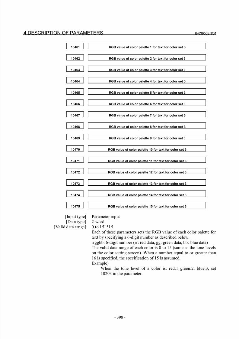
8/21/2019 30i Parameter Manual
http://slidepdf.com/reader/full/30i-parameter-manual 410/493
4.DESCRIPTION OF PARAMETERS B-63950EN/01
- 398 -
10461 RGB value of color palette 1 for text for color set 3
10462 RGB value of color palette 2 for text for color set 3
10463 RGB value of color palette 3 for text for color set 3
10464 RGB value of color palette 4 for text for color set 3
10465 RGB value of color palette 5 for text for color set 3
10466 RGB value of color palette 6 for text for color set 3
10467 RGB value of color palette 7 for text for color set 3
10468 RGB value of color palette 8 for text for color set 3
10469 RGB value of color palette 9 for text for color set 3
10470 RGB value of color palette 10 for text for color set 3
10471 RGB value of color palette 11 for text for color set 3
10472 RGB value of color palette 12 for text for color set 3
10473 RGB value of color palette 13 for text for color set 3
10474 RGB value of color palette 14 for text for color set 3
10475 RGB value of color palette 15 for text for color set 3
[Input type] Parameter input
[Data type] 2-word
[Valid data range] 0 to 151515
Each of these parameters sets the RGB value of each color palette for
text by specifying a 6-digit number as described below.rrggbb: 6-digit number (rr: red data, gg: green data, bb: blue data)
The valid data range of each color is 0 to 15 (same as the tone levels
on the color setting screen). When a number equal to or greater than
16 is specified, the specification of 15 is assumed.
Example)
When the tone level of a color is: red:1 green:2, blue:3, set
10203 in the parameter.
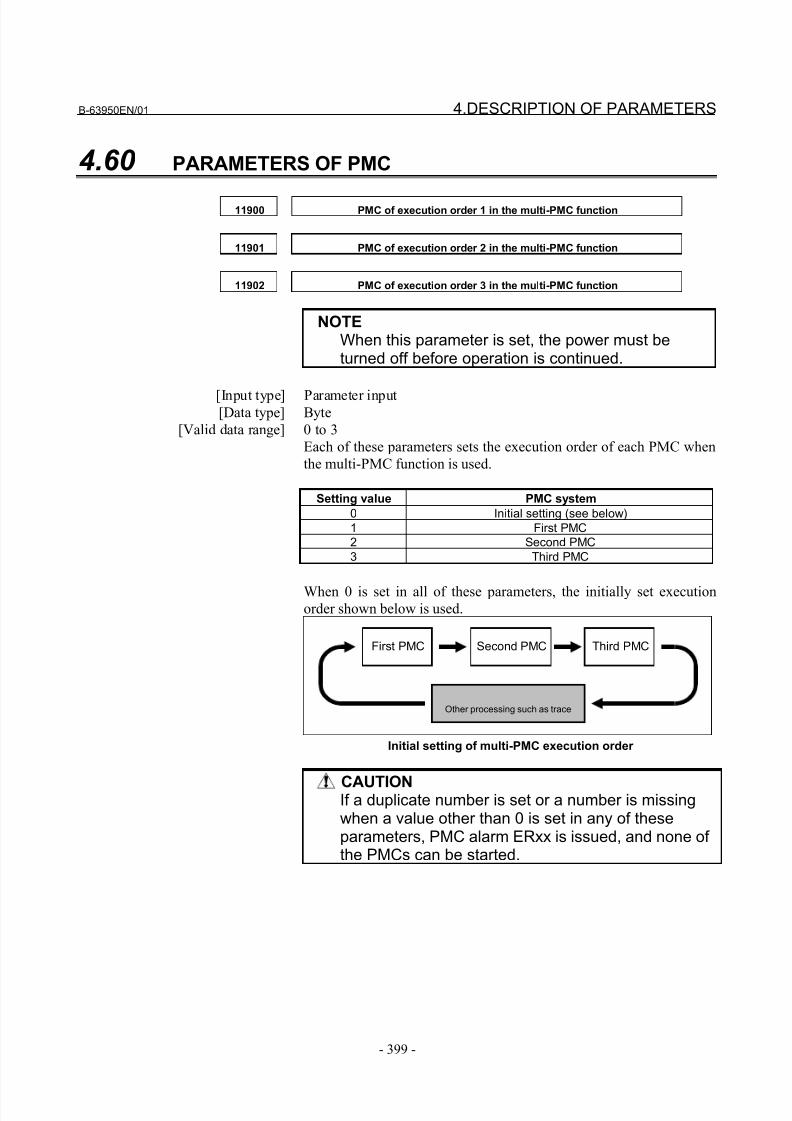
8/21/2019 30i Parameter Manual
http://slidepdf.com/reader/full/30i-parameter-manual 411/493
B-63950EN/01 4.DESCRIPTION OF PARAMETERS
- 399 -
4.60 PARAMETERS OF PMC
11900 PMC of execution order 1 in the multi-PMC function
11901 PMC of execution order 2 in the multi-PMC function
11902 PMC of execution order 3 in the multi-PMC function
NOTEWhen this parameter is set, the power must beturned off before operation is continued.
[Input type] Parameter input[Data type] Byte
[Valid data range] 0 to 3
Each of these parameters sets the execution order of each PMC when
the multi-PMC function is used.
Setting value PMC system
0 Initial setting (see below)
1 First PMC
2 Second PMC
3 Third PMC
When 0 is set in all of these parameters, the initially set executionorder shown below is used.
First PMC Second PMC Third PMC
Other processing such as trace
Initial setting of multi-PMC execution order
CAUTIONIf a duplicate number is set or a number is missingwhen a value other than 0 is set in any of theseparameters, PMC alarm ERxx is issued, and none of the PMCs can be started.
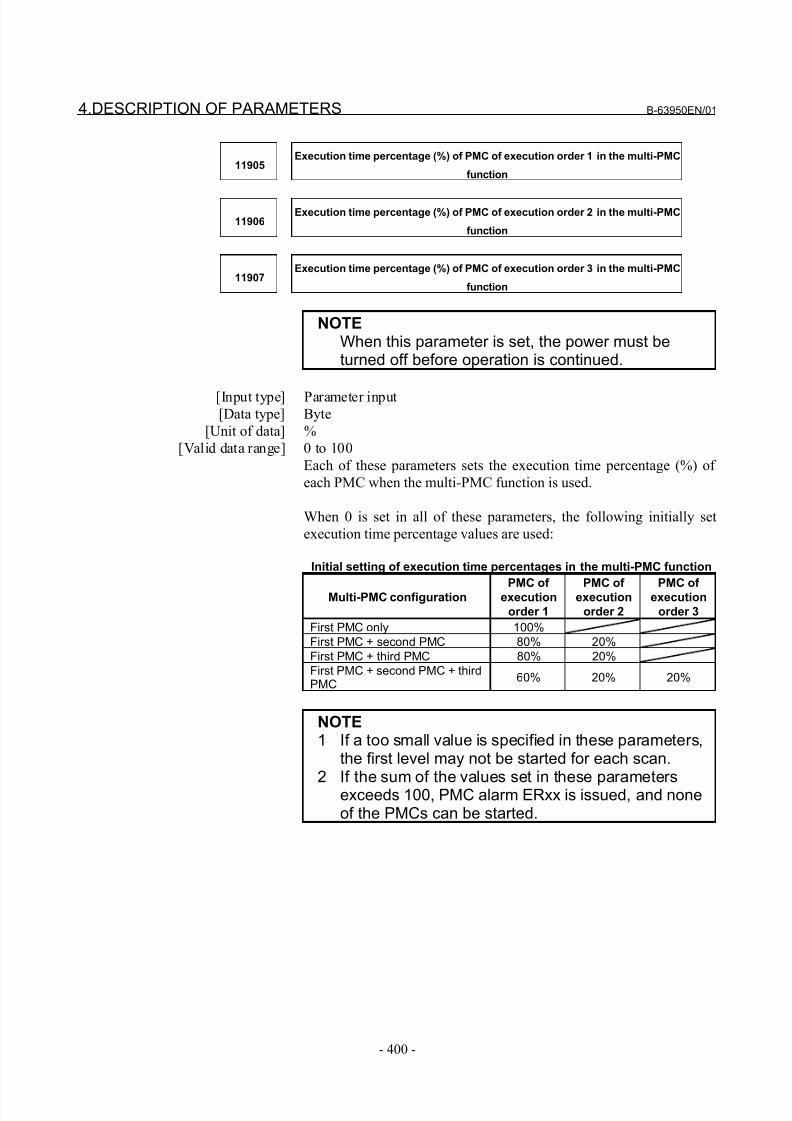
8/21/2019 30i Parameter Manual
http://slidepdf.com/reader/full/30i-parameter-manual 412/493
4.DESCRIPTION OF PARAMETERS B-63950EN/01
- 400 -
11905Execution time percentage (%) of PMC of execution order 1 in the multi-PMC
function
11906Execution time percentage (%) of PMC of execution order 2 in the multi-PMC
function
11907Execution time percentage (%) of PMC of execution order 3 in the multi-PMC
function
NOTEWhen this parameter is set, the power must beturned off before operation is continued.
[Input type] Parameter input[Data type] Byte
[Unit of data] %
[Valid data range] 0 to 100
Each of these parameters sets the execution time percentage (%) of
each PMC when the multi-PMC function is used.
When 0 is set in all of these parameters, the following initially set
execution time percentage values are used:
Initial setting of execution time percentages in the multi-PMC function
Multi-PMC configuration PMC of execution
order 1
PMC of execution
order 2
PMC of execution
order 3
First PMC only 100%
First PMC + second PMC 80% 20%
First PMC + third PMC 80% 20%
First PMC + second PMC + thirdPMC
60% 20% 20%
NOTE1 If a too small value is specified in these parameters,
the first level may not be started for each scan.2 If the sum of the values set in these parameters
exceeds 100, PMC alarm ERxx is issued, and noneof the PMCs can be started.
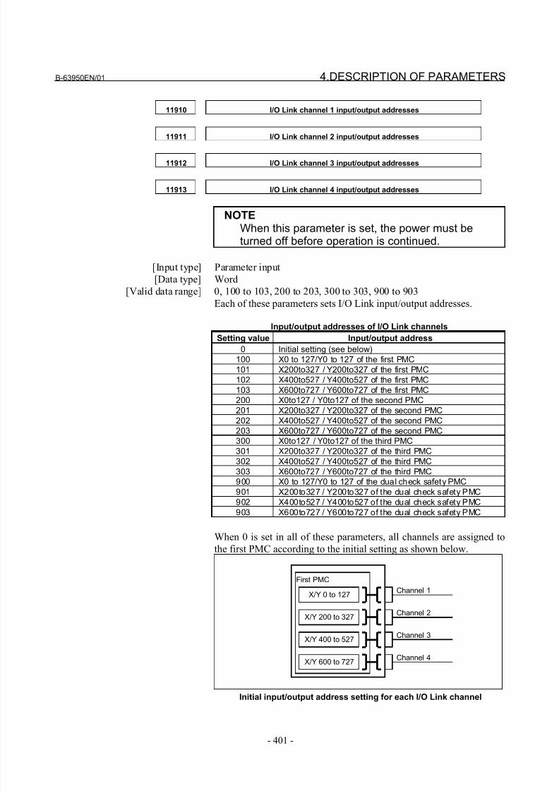
8/21/2019 30i Parameter Manual
http://slidepdf.com/reader/full/30i-parameter-manual 413/493
B-63950EN/01 4.DESCRIPTION OF PARAMETERS
- 401 -
11910 I/O Link channel 1 input/output addresses
11911 I/O Link channel 2 input/output addresses
11912 I/O Link channel 3 input/output addresses
11913 I/O Link channel 4 input/output addresses
NOTEWhen this parameter is set, the power must beturned off before operation is continued.
[Input type] Parameter input
[Data type] Word[Valid data range] 0, 100 to 103, 200 to 203, 300 to 303, 900 to 903
Each of these parameters sets I/O Link input/output addresses.
Input/output addresses of I/O Link channels
Setting value Input/output address
0 Initial setting (see below)
100 X0 to 127/Y0 to 127 of the first PMC
101 X200to327 / Y200to327 of the first PMC
102 X400to527 / Y400to527 of the first PMC
103 X600to727 / Y600to727 of the first PMC
200 X0to127 / Y0to127 of the second PMC
201 X200to327 / Y200to327 of the second PMC
202 X400to527 / Y400to527 of the second PMC
203 X600to727 / Y600to727 of the second PMC
300 X0to127 / Y0to127 of the third PMC
301 X200to327 / Y200to327 of the third PMC
302 X400to527 / Y400to527 of the third PMC
303 X600to727 / Y600to727 of the third PMC
900 X0 to 127/Y0 to 127 of the dual check safety PMC
901 X200to327 / Y200to327 of the dual check safety PMC
902 X400to527 / Y400to527 of the dual check safety PMC
903 X600to727 / Y600to727 of the dual check safety PMC
When 0 is set in all of these parameters, all channels are assigned to
the first PMC according to the initial setting as shown below.
First PMC
X/Y 0 to 127
X/Y 200 to 327
X/Y 400 to 527
X/Y 600 to 727
Channel 1
Channel 2
Channel 3
Channel 4
Initial input/output address setting for each I/O Link channel

8/21/2019 30i Parameter Manual
http://slidepdf.com/reader/full/30i-parameter-manual 414/493
4.DESCRIPTION OF PARAMETERS B-63950EN/01
- 402 -
CAUTION1 If a duplicate number is set when a value other than
0 is set in any of these parameters, PMC alarmERxx is issued, and none of the PMCs can bestarted.
2 If a parameter is not set, the assignment of PMCaddresses to the channel is disabled.
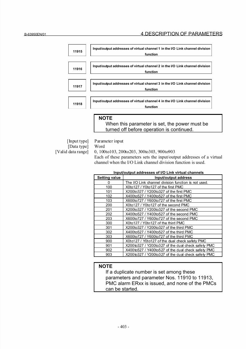
8/21/2019 30i Parameter Manual
http://slidepdf.com/reader/full/30i-parameter-manual 415/493
B-63950EN/01 4.DESCRIPTION OF PARAMETERS
- 403 -
11915Input/output addresses of virtual channel 1 in the I/O Link channel division
function
11916Input/output addresses of virtual channel 2 in the I/O Link channel division
function
11917Input/output addresses of virtual channel 3 in the I/O Link channel division
function
11918Input/output addresses of virtual channel 4 in the I/O Link channel division
function
NOTE
When this parameter is set, the power must beturned off before operation is continued.
[Input type] Parameter input
[Data type] Word
[Valid data range] 0, 100to103, 200to203, 300to303, 900to903
Each of these parameters sets the input/output addresses of a virtual
channel when the I/O Link channel division function is used.
Input/output addresses of I/O Link virtual channels
Setting value Input/output address
0 The I/O Link channel division function is not used.100 X0to127 / Y0to127 of the first PMC
101 X200to327 / Y200to327 of the first PMC
102 X400to527 / Y400to527 of the first PMC
103 X600to727 / Y600to727 of the first PMC
200 X0to127 / Y0to127 of the second PMC
201 X200to327 / Y200to327 of the second PMC
202 X400to527 / Y400to527 of the second PMC
203 X600to727 / Y600to727 of the second PMC
300 X0to127 / Y0to127 of the third PMC
301 X200to327 / Y200to327 of the third PMC
302 X400to527 / Y400to527 of the third PMC
303 X600to727 / Y600to727 of the third PMC
900 X0to127 / Y0to127 of the dual check safety PMC
901 X200to327 / Y200to327 of the dual check safety PMC902 X400to527 / Y400to527 of the dual check safety PMC
903 X200to327 / Y200to327 of the dual check safety PMC
NOTEIf a duplicate number is set among theseparameters and parameter Nos. 11910 to 11913,PMC alarm ERxx is issued, and none of the PMCscan be started.
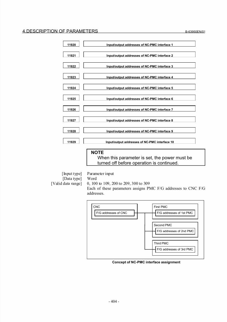
8/21/2019 30i Parameter Manual
http://slidepdf.com/reader/full/30i-parameter-manual 416/493
4.DESCRIPTION OF PARAMETERS B-63950EN/01
- 404 -
11920 Input/output addresses of NC-PMC interface 1
11921 Input/output addresses of NC-PMC interface 2
11922 Input/output addresses of NC-PMC interface 3
11923 Input/output addresses of NC-PMC interface 4
11924 Input/output addresses of NC-PMC interface 5
11925 Input/output addresses of NC-PMC interface 6
11926 Input/output addresses of NC-PMC interface 7
11927 Input/output addresses of NC-PMC interface 8
11928 Input/output addresses of NC-PMC interface 9
11929 Input/output addresses of NC-PMC interface 10
NOTEWhen this parameter is set, the power must beturned off before operation is continued.
[Input type] Parameter input
[Data type] Word
[Valid data range] 0, 100 to 109, 200 to 209, 300 to 309
Each of these parameters assigns PMC F/G addresses to CNC F/G
addresses.
CNC First PMC
F/G addresses of CNC F/G addresses of 1st PMC
Second PMC
F/G addresses of 2nd PMC
Third PMC
F/G addresses of 3rd PMC
Concept of NC-PMC interface assignment
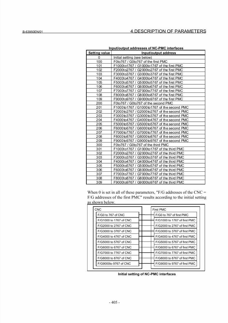
8/21/2019 30i Parameter Manual
http://slidepdf.com/reader/full/30i-parameter-manual 417/493
B-63950EN/01 4.DESCRIPTION OF PARAMETERS
- 405 -
Input/output addresses of NC-PMC interfaces
Setting value Input/output address
0 Initial setting (see below)100 F0to767 / G0to767 of the first PMC
101 F1000to1767 / G1000to1767 of the first PMC
102 F2000to2767 / G2000to2767 of the first PMC
103 F3000to3767 / G3000to3767 of the first PMC
104 F4000to4767 / G4000to4767 of the first PMC
105 F5000to5767 / G5000to5767 of the first PMC
106 F6000to6767 / G6000to6767 of the first PMC
107 F7000to7767 / G7000to7767 of the first PMC
108 F8000to8767 / G8000to8767 of the first PMC
109 F9000to9767 / G9000to9767 of the first PMC
200 F0to767 / G0to767 of the second PMC
201 F1000to1767 / G1000to1767 of the second PMC
202 F2000to2767 / G2000to2767 of the second PMC203 F3000to3767 / G3000to3767 of the second PMC
204 F4000to4767 / G4000to4767 of the second PMC
205 F5000to5767 / G5000to5767 of the second PMC
206 F6000to6767 / G6000to6767 of the second PMC
207 F7000to7767 / G7000to7767 of the second PMC
208 F8000to8767 / G8000to8767 of the second PMC
209 F9000to9767 / G9000to9767 of the second PMC
300 F0to767 / G0to767 of the third PMC
301 F1000to1767 / G1000to1767 of the third PMC
302 F2000to2767 / G2000to2767 of the third PMC
303 F3000to3767 / G3000to3767 of the third PMC
304 F4000to4767 / G4000to4767 of the third PMC
305 F5000to5767 / G5000to5767 of the third PMC
306 F6000to6767 / G6000to6767 of the third PMC307 F7000to7767 / G7000to7767 of the third PMC
308 F8000to8767 / G8000to8767 of the third PMC
309 F9000to9767 / G9000to9767 of the third PMC
When 0 is set in all of these parameters, "F/G addresses of the CNC =
F/G addresses of the first PMC" results according to the initial setting
as shown below.
CNC First PMC
F/G0 to 767 of CNC
F/G1000 to 1767 of CNC
F/G2000 to 2767 of CNCF/G3000 to 3767 of CNC
F/G4000 to 4767 of CNC
F/G5000 to 5767 of CNC
F/G6000 to 6767 of CNC
F/G7000 to 7767 of CNC
F/G8000 to 8767 of CNC
F/G9000to 9767 of CNC
F/G0 to 767 of first PMC
F/G1000 to 1767 of first PMC
F/G2000 to 2767 of first PMCF/G3000 to 3767 of first PMC
F/G4000 to 4767 of first PMC
F/G5000 to 5767 of first PMC
F/G6000 to 6767 of first PMC
F/G7000 to 7767 of first PMC
F/G8000 to 8767 of first PMC
F/G9000 to 9767 of first PMC
Initial setting of NC-PMC interfaces

8/21/2019 30i Parameter Manual
http://slidepdf.com/reader/full/30i-parameter-manual 418/493
4.DESCRIPTION OF PARAMETERS B-63950EN/01
- 406 -
CAUTION1 If a duplicate number is set when a value other than
0 is set in any of these parameters, PMC alarmERxx is issued, and none of the PMCs can bestarted.
2 If a parameter is not set, the assignment of PMCaddresses to the F/G addresses of the NC isdisabled.
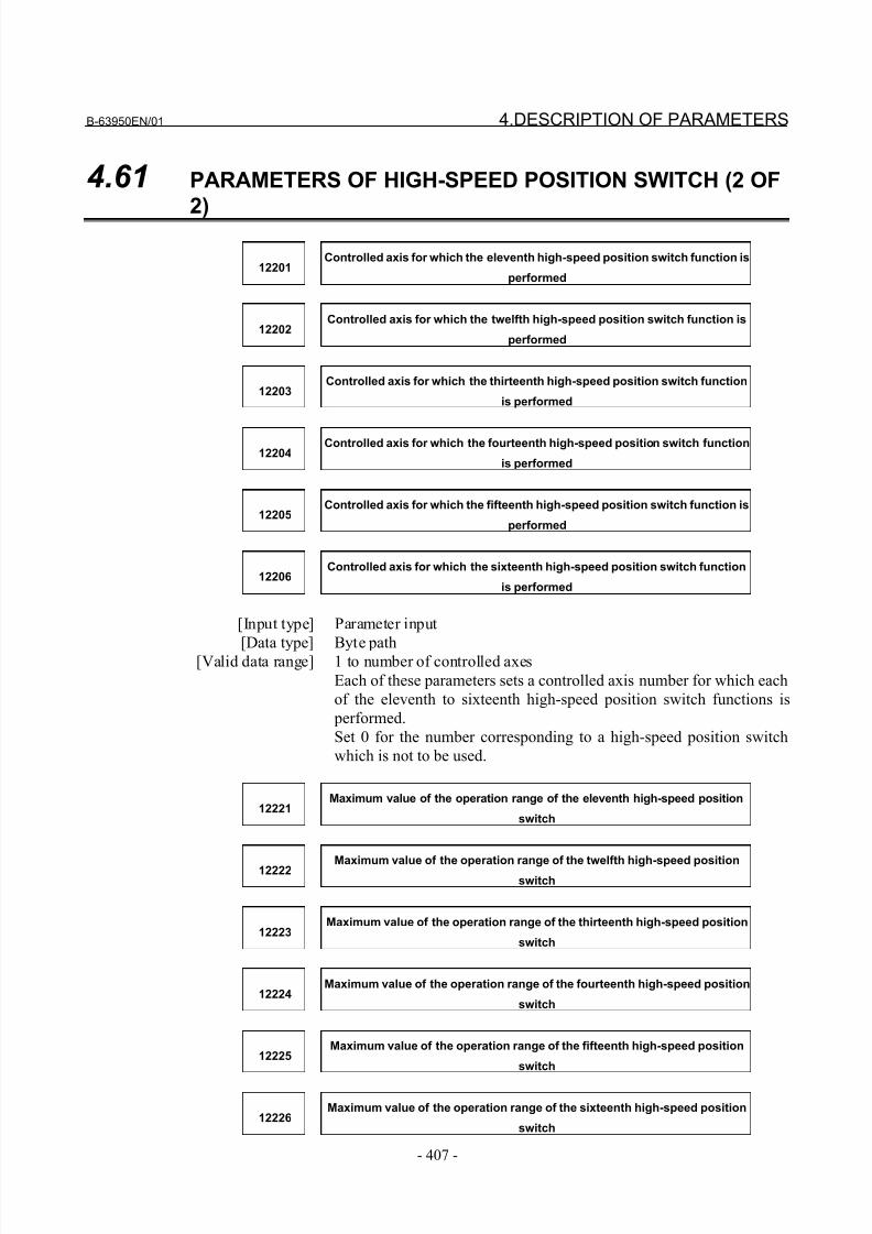
8/21/2019 30i Parameter Manual
http://slidepdf.com/reader/full/30i-parameter-manual 419/493
B-63950EN/01 4.DESCRIPTION OF PARAMETERS
- 407 -
4.61 PARAMETERS OF HIGH-SPEED POSITION SWITCH (2 OF
2)
12201Controlled axis for which the eleventh high-speed position switch function is
performed
12202Controlled axis for which the twelfth high-speed position switch function is
performed
12203Controlled axis for which the thirteenth high-speed position switch function
is performed
12204Controlled axis for which the fourteenth high-speed position switch function
is performed
12205Controlled axis for which the fifteenth high-speed position switch function is
performed
12206Controlled axis for which the sixteenth high-speed position switch function
is performed
[Input type] Parameter input
[Data type] Byte path[Valid data range] 1 to number of controlled axes
Each of these parameters sets a controlled axis number for which each
of the eleventh to sixteenth high-speed position switch functions is
performed.
Set 0 for the number corresponding to a high-speed position switch
which is not to be used.
12221Maximum value of the operation range of the eleventh high-speed position
switch
12222 Maximum value of the operation range of the twelfth high-speed positionswitch
12223Maximum value of the operation range of the thirteenth high-speed position
switch
12224Maximum value of the operation range of the fourteenth high-speed position
switch
12225Maximum value of the operation range of the fifteenth high-speed position
switch
12226Maximum value of the operation range of the sixteenth high-speed position
switch
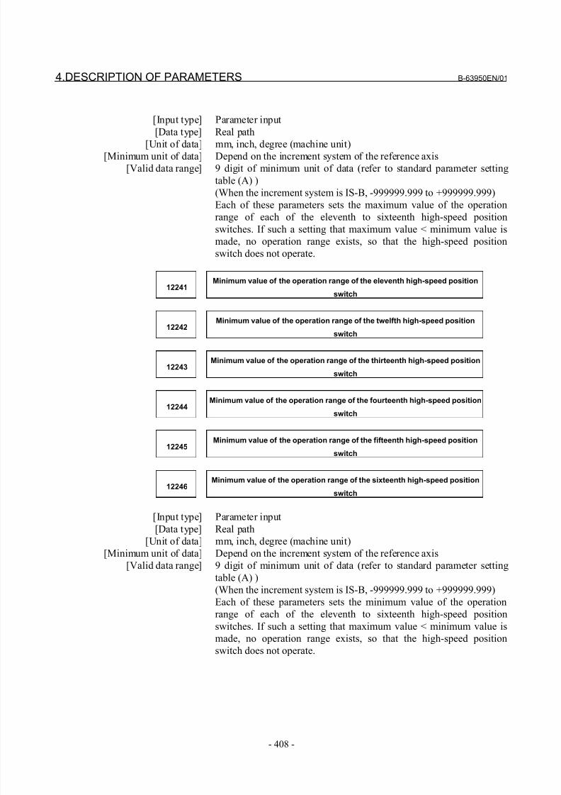
8/21/2019 30i Parameter Manual
http://slidepdf.com/reader/full/30i-parameter-manual 420/493
4.DESCRIPTION OF PARAMETERS B-63950EN/01
- 408 -
[Input type] Parameter input
[Data type] Real path
[Unit of data] mm, inch, degree (machine unit)
[Minimum unit of data] Depend on the increment system of the reference axis
[Valid data range] 9 digit of minimum unit of data (refer to standard parameter setting
table (A) )
(When the increment system is IS-B, -999999.999 to +999999.999)
Each of these parameters sets the maximum value of the operation
range of each of the eleventh to sixteenth high-speed position
switches. If such a setting that maximum value < minimum value is
made, no operation range exists, so that the high-speed position
switch does not operate.
12241Minimum value of the operation range of the eleventh high-speed position
switch
12242Minimum value of the operation range of the twelfth high-speed position
switch
12243Minimum value of the operation range of the thirteenth high-speed position
switch
12244Minimum value of the operation range of the fourteenth high-speed position
switch
12245Minimum value of the operation range of the fifteenth high-speed position
switch
12246Minimum value of the operation range of the sixteenth high-speed position
switch
[Input type] Parameter input
[Data type] Real path
[Unit of data] mm, inch, degree (machine unit)
[Minimum unit of data] Depend on the increment system of the reference axis[Valid data range] 9 digit of minimum unit of data (refer to standard parameter setting
table (A) )
(When the increment system is IS-B, -999999.999 to +999999.999)
Each of these parameters sets the minimum value of the operation
range of each of the eleventh to sixteenth high-speed position
switches. If such a setting that maximum value < minimum value is
made, no operation range exists, so that the high-speed position
switch does not operate.
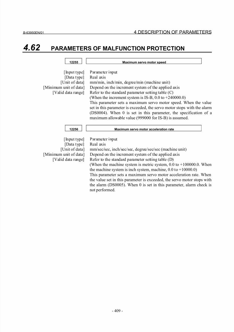
8/21/2019 30i Parameter Manual
http://slidepdf.com/reader/full/30i-parameter-manual 421/493
B-63950EN/01 4.DESCRIPTION OF PARAMETERS
- 409 -
4.62 PARAMETERS OF MALFUNCTION PROTECTION
12255 Maximum servo motor speed
[Input type] Parameter input
[Data type] Real axis
[Unit of data] mm/min, inch/min, degree/min (machine unit)
[Minimum unit of data] Depend on the increment system of the applied axis
[Valid data range] Refer to the standard parameter setting table (C)
(When the increment system is IS-B, 0.0 to +240000.0)
This parameter sets a maximum servo motor speed. When the value
set in this parameter is exceeded, the servo motor stops with the alarm
(DS0004). When 0 is set in this parameter, the specification of a
maximum allowable value (999000 for IS-B) is assumed.
12256 Maximum servo motor acceleration rate
[Input type] Parameter input
[Data type] Real axis
[Unit of data] mm/sec/sec, inch/sec/sec, degree/sec/sec (machine unit)
[Minimum unit of data] Depend on the increment system of the applied axis
[Valid data range] Refer to the standard parameter setting table (D)
(When the machine system is metric system, 0.0 to +100000.0. When
the machine system is inch system, machine, 0.0 to +10000.0)
This parameter sets a maximum servo motor acceleration rate. Whenthe value set in this parameter is exceeded, the servo motor stops with
the alarm (DS0005). When 0 is set in this parameter, alarm check is
not performed.
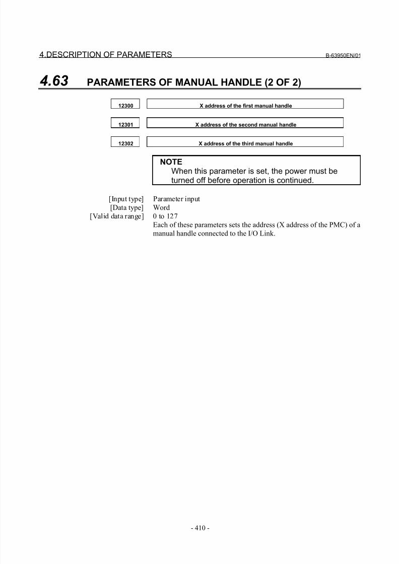
8/21/2019 30i Parameter Manual
http://slidepdf.com/reader/full/30i-parameter-manual 422/493
4.DESCRIPTION OF PARAMETERS B-63950EN/01
- 410 -
4.63 PARAMETERS OF MANUAL HANDLE (2 OF 2)
12300 X address of the first manual handle
12301 X address of the second manual handle
12302 X address of the third manual handle
NOTEWhen this parameter is set, the power must beturned off before operation is continued.
[Input type] Parameter input[Data type] Word
[Valid data range] 0 to 127
Each of these parameters sets the address (X address of the PMC) of a
manual handle connected to the I/O Link.
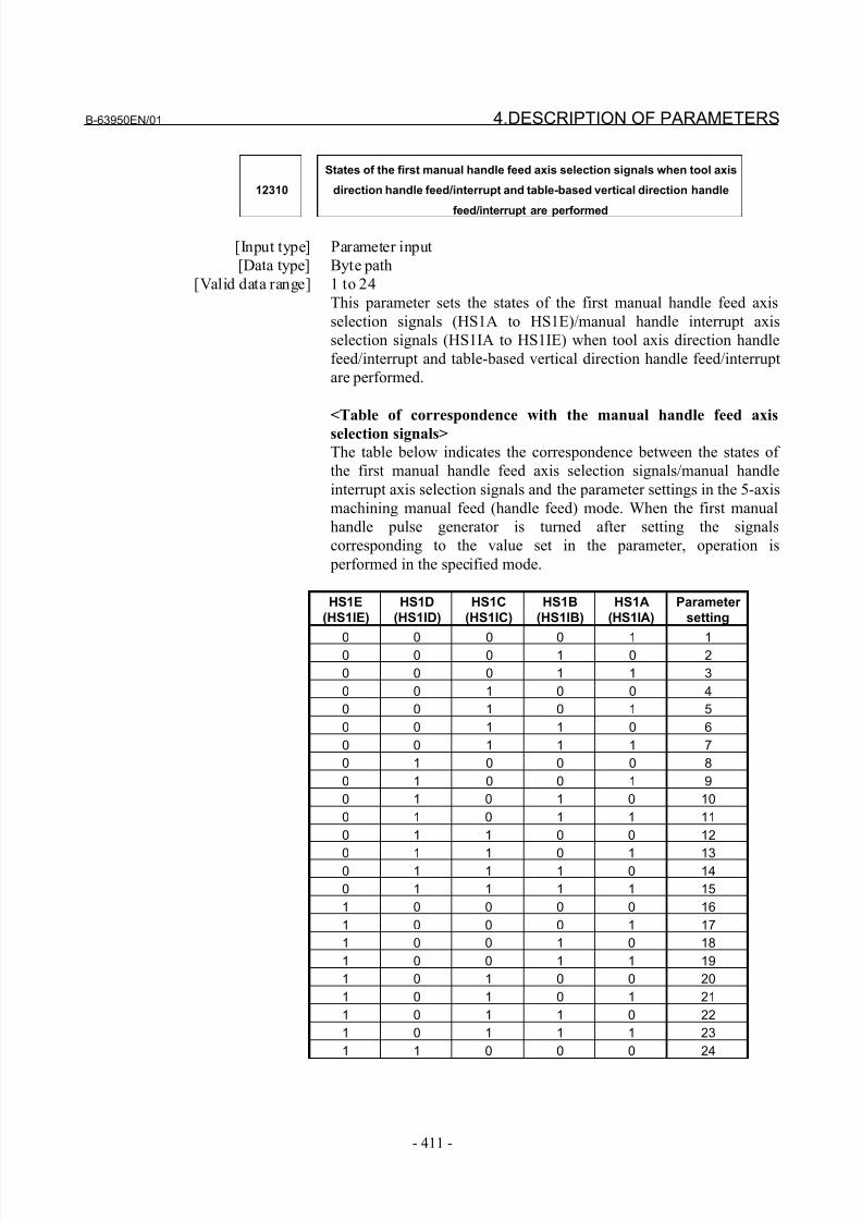
8/21/2019 30i Parameter Manual
http://slidepdf.com/reader/full/30i-parameter-manual 423/493
B-63950EN/01 4.DESCRIPTION OF PARAMETERS
- 411 -
12310
States of the first manual handle feed axis selection signals when tool axis
direction handle feed/interrupt and table-based vertical direction handle
feed/interrupt are performed
[Input type] Parameter input
[Data type] Byte path
[Valid data range] 1 to 24
This parameter sets the states of the first manual handle feed axis
selection signals (HS1A to HS1E)/manual handle interrupt axis
selection signals (HS1IA to HS1IE) when tool axis direction handle
feed/interrupt and table-based vertical direction handle feed/interrupt
are performed.
<Table of correspondence with the manual handle feed axis
selection signals>
The table below indicates the correspondence between the states of
the first manual handle feed axis selection signals/manual handle
interrupt axis selection signals and the parameter settings in the 5-axis
machining manual feed (handle feed) mode. When the first manual
handle pulse generator is turned after setting the signals
corresponding to the value set in the parameter, operation is
performed in the specified mode.
HS1E
(HS1IE)
HS1D
(HS1ID)
HS1C
(HS1IC)
HS1B
(HS1IB)
HS1A
(HS1IA)
Parameter
setting
0 0 0 0 1 10 0 0 1 0 2
0 0 0 1 1 3
0 0 1 0 0 4
0 0 1 0 1 5
0 0 1 1 0 6
0 0 1 1 1 7
0 1 0 0 0 8
0 1 0 0 1 9
0 1 0 1 0 10
0 1 0 1 1 11
0 1 1 0 0 12
0 1 1 0 1 130 1 1 1 0 14
0 1 1 1 1 15
1 0 0 0 0 16
1 0 0 0 1 17
1 0 0 1 0 18
1 0 0 1 1 19
1 0 1 0 0 20
1 0 1 0 1 21
1 0 1 1 0 22
1 0 1 1 1 23
1 1 0 0 0 24
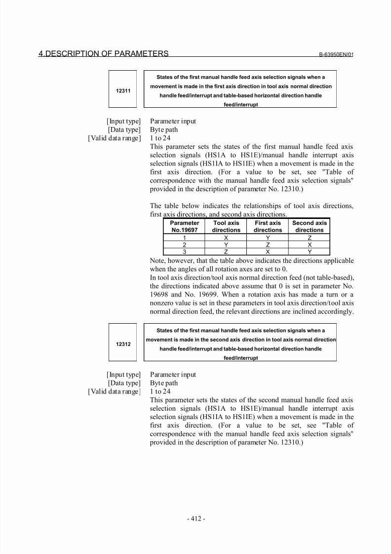
8/21/2019 30i Parameter Manual
http://slidepdf.com/reader/full/30i-parameter-manual 424/493
4.DESCRIPTION OF PARAMETERS B-63950EN/01
- 412 -
12311
States of the first manual handle feed axis selection signals when a
movement is made in the first axis direction in tool axis normal direction
handle feed/interrupt and table-based horizontal direction handlefeed/interrupt
[Input type] Parameter input
[Data type] Byte path
[Valid data range] 1 to 24
This parameter sets the states of the first manual handle feed axis
selection signals (HS1A to HS1E)/manual handle interrupt axis
selection signals (HS1IA to HS1IE) when a movement is made in the
first axis direction. (For a value to be set, see "Table of
correspondence with the manual handle feed axis selection signals"
provided in the description of parameter No. 12310.)
The table below indicates the relationships of tool axis directions,
first axis directions, and second axis directions.Parameter
No.19697
Tool axis
directions
First axis
directions
Second axis
directions
1 X Y Z2 Y Z X3 Z X Y
Note, however, that the table above indicates the directions applicable
when the angles of all rotation axes are set to 0.
In tool axis direction/tool axis normal direction feed (not table-based),
the directions indicated above assume that 0 is set in parameter No.
19698 and No. 19699. When a rotation axis has made a turn or a
nonzero value is set in these parameters in tool axis direction/tool axis
normal direction feed, the relevant directions are inclined accordingly.
12312
States of the first manual handle feed axis selection signals when a
movement is made in the second axis direction in tool axis normal direction
handle feed/interrupt and table-based horizontal direction handle
feed/interrupt
[Input type] Parameter input
[Data type] Byte path
[Valid data range] 1 to 24
This parameter sets the states of the second manual handle feed axis
selection signals (HS1A to HS1E)/manual handle interrupt axis
selection signals (HS1IA to HS1IE) when a movement is made in the
first axis direction. (For a value to be set, see "Table of
correspondence with the manual handle feed axis selection signals"
provided in the description of parameter No. 12310.)
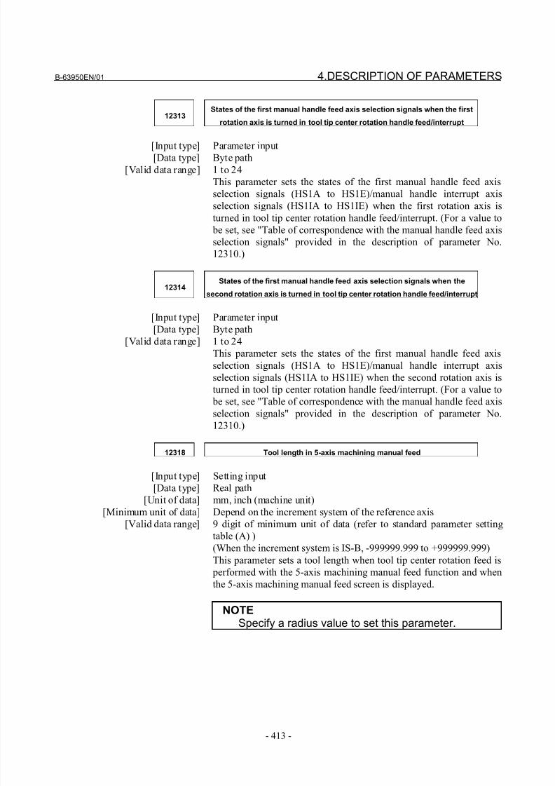
8/21/2019 30i Parameter Manual
http://slidepdf.com/reader/full/30i-parameter-manual 425/493
B-63950EN/01 4.DESCRIPTION OF PARAMETERS
- 413 -
12313States of the first manual handle feed axis selection signals when the first
rotation axis is turned in tool tip center rotation handle feed/interrupt
[Input type] Parameter input
[Data type] Byte path
[Valid data range] 1 to 24
This parameter sets the states of the first manual handle feed axis
selection signals (HS1A to HS1E)/manual handle interrupt axis
selection signals (HS1IA to HS1IE) when the first rotation axis is
turned in tool tip center rotation handle feed/interrupt. (For a value to
be set, see "Table of correspondence with the manual handle feed axis
selection signals" provided in the description of parameter No.
12310.)
12314States of the first manual handle feed axis selection signals when the
second rotation axis is turned in tool tip center rotation handle feed/interrupt
[Input type] Parameter input
[Data type] Byte path
[Valid data range] 1 to 24
This parameter sets the states of the first manual handle feed axis
selection signals (HS1A to HS1E)/manual handle interrupt axis
selection signals (HS1IA to HS1IE) when the second rotation axis is
turned in tool tip center rotation handle feed/interrupt. (For a value to
be set, see "Table of correspondence with the manual handle feed axis
selection signals" provided in the description of parameter No.12310.)
12318 Tool length in 5-axis machining manual feed
[Input type] Setting input
[Data type] Real path
[Unit of data] mm, inch (machine unit)
[Minimum unit of data] Depend on the increment system of the reference axis
[Valid data range] 9 digit of minimum unit of data (refer to standard parameter setting
table (A) )
(When the increment system is IS-B, -999999.999 to +999999.999)This parameter sets a tool length when tool tip center rotation feed is
performed with the 5-axis machining manual feed function and when
the 5-axis machining manual feed screen is displayed.
NOTESpecify a radius value to set this parameter.
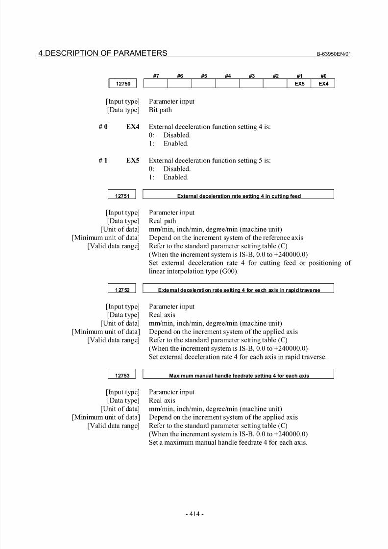
8/21/2019 30i Parameter Manual
http://slidepdf.com/reader/full/30i-parameter-manual 426/493
4.DESCRIPTION OF PARAMETERS B-63950EN/01
- 414 -
#7 #6 #5 #4 #3 #2 #1 #0
12750 EX5 EX4
[Input type] Parameter input
[Data type] Bit path
# 0 EX4 External deceleration function setting 4 is:
0: Disabled.
1: Enabled.
# 1 EX5 External deceleration function setting 5 is:
0: Disabled.
1: Enabled.
12751 External deceleration rate setting 4 in cutting feed
[Input type] Parameter input
[Data type] Real path
[Unit of data] mm/min, inch/min, degree/min (machine unit)
[Minimum unit of data] Depend on the increment system of the reference axis
[Valid data range] Refer to the standard parameter setting table (C)
(When the increment system is IS-B, 0.0 to +240000.0)
Set external deceleration rate 4 for cutting feed or positioning of
linear interpolation type (G00).
12752 External deceleration rate setting 4 for each axis in rapid traverse
[Input type] Parameter input
[Data type] Real axis
[Unit of data] mm/min, inch/min, degree/min (machine unit)
[Minimum unit of data] Depend on the increment system of the applied axis
[Valid data range] Refer to the standard parameter setting table (C)
(When the increment system is IS-B, 0.0 to +240000.0)
Set external deceleration rate 4 for each axis in rapid traverse.
12753 Maximum manual handle feedrate setting 4 for each axis
[Input type] Parameter input
[Data type] Real axis
[Unit of data] mm/min, inch/min, degree/min (machine unit)
[Minimum unit of data] Depend on the increment system of the applied axis
[Valid data range] Refer to the standard parameter setting table (C)
(When the increment system is IS-B, 0.0 to +240000.0)
Set a maximum manual handle feedrate 4 for each axis.
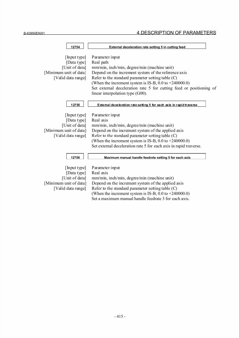
8/21/2019 30i Parameter Manual
http://slidepdf.com/reader/full/30i-parameter-manual 427/493
B-63950EN/01 4.DESCRIPTION OF PARAMETERS
- 415 -
12754 External deceleration rate setting 5 in cutting feed
[Input type] Parameter input[Data type] Real path
[Unit of data] mm/min, inch/min, degree/min (machine unit)
[Minimum unit of data] Depend on the increment system of the reference axis
[Valid data range] Refer to the standard parameter setting table (C)
(When the increment system is IS-B, 0.0 to +240000.0)
Set external deceleration rate 5 for cutting feed or positioning of
linear interpolation type (G00).
12755 External deceleration rate setting 5 for each axis in rapid traverse
[Input type] Parameter input
[Data type] Real axis
[Unit of data] mm/min, inch/min, degree/min (machine unit)
[Minimum unit of data] Depend on the increment system of the applied axis
[Valid data range] Refer to the standard parameter setting table (C)
(When the increment system is IS-B, 0.0 to +240000.0)
Set external deceleration rate 5 for each axis in rapid traverse.
12756 Maximum manual handle feedrate setting 5 for each axis
[Input type] Parameter input
[Data type] Real axis
[Unit of data] mm/min, inch/min, degree/min (machine unit)[Minimum unit of data] Depend on the increment system of the applied axis
[Valid data range] Refer to the standard parameter setting table (C)
(When the increment system is IS-B, 0.0 to +240000.0)
Set a maximum manual handle feedrate 3 for each axis.
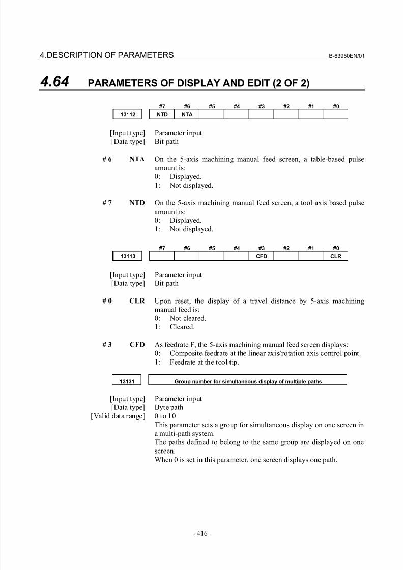
8/21/2019 30i Parameter Manual
http://slidepdf.com/reader/full/30i-parameter-manual 428/493
4.DESCRIPTION OF PARAMETERS B-63950EN/01
- 416 -
4.64 PARAMETERS OF DISPLAY AND EDIT (2 OF 2)
#7 #6 #5 #4 #3 #2 #1 #0
13112 NTD NTA
[Input type] Parameter input
[Data type] Bit path
# 6 NTA On the 5-axis machining manual feed screen, a table-based pulse
amount is:
0: Displayed.
1: Not displayed.
# 7 NTD On the 5-axis machining manual feed screen, a tool axis based pulse
amount is:
0: Displayed.
1: Not displayed.
#7 #6 #5 #4 #3 #2 #1 #0
13113 CFD CLR
[Input type] Parameter input
[Data type] Bit path
# 0 CLR Upon reset, the display of a travel distance by 5-axis machiningmanual feed is:
0: Not cleared.
1: Cleared.
# 3 CFD As feedrate F, the 5-axis machining manual feed screen displays:
0: Composite feedrate at the linear axis/rotation axis control point.
1: Feedrate at the tool tip.
13131 Group number for simultaneous display of multiple paths
[Input type] Parameter input[Data type] Byte path
[Valid data range] 0 to 10
This parameter sets a group for simultaneous display on one screen in
a multi-path system.
The paths defined to belong to the same group are displayed on one
screen.
When 0 is set in this parameter, one screen displays one path.
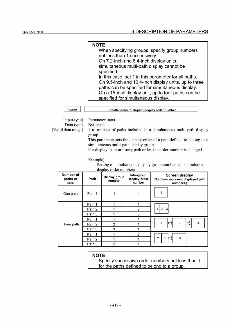
8/21/2019 30i Parameter Manual
http://slidepdf.com/reader/full/30i-parameter-manual 429/493
B-63950EN/01 4.DESCRIPTION OF PARAMETERS
- 417 -
NOTEWhen specifying groups, specify group numbers
not less than 1 successively.On 7.2-inch and 8.4-inch display units,simultaneous multi-path display cannot bespecified.In this case, set 1 in this parameter for all paths.On 9.5-inch and 10.4-inch display units, up to threepaths can be specified for simultaneous display.On a 15-inch display unit, up to four paths can bespecified for simultaneous display.
13132 Simultaneous multi-path display order number
[Input type] Parameter input
[Data type] Byte path
[Valid data range] 1 to number of paths included in a simultaneous multi-path display
group
This parameter sets the display order of a path defined to belong to a
simultaneous multi-path display group.
For display in an arbitrary path order, the order number is changed.
Example)
Setting of simultaneous display group numbers and simultaneous
display order numbersNumber of
paths of
CNC
PathDisplay group
number
Intra-group
display order number
Screen display(Numbers represent displayed path
numbers.)
One path Path 1 1 1
Path 1 1 1
Path 2 1 2
Path 3 1 3
Path 1 1 1
Path 2 2 1
Path 3 3 1
Path 1 1 2
Path 2 1 1
Three path
Path 3 2 1
NOTESpecify successive order numbers not less than 1for the paths defined to belong to a group.
1
1 2 3
2 1 3
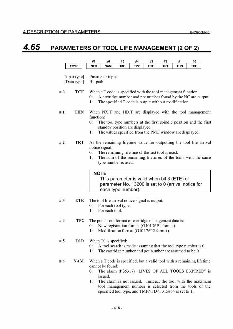
8/21/2019 30i Parameter Manual
http://slidepdf.com/reader/full/30i-parameter-manual 430/493
4.DESCRIPTION OF PARAMETERS B-63950EN/01
- 418 -
4.65 PARAMETERS OF TOOL LIFE MANAGEMENT (2 OF 2)
#7 #6 #5 #4 #3 #2 #1 #0
13200 NFD NAM T0O TP2 ETE TRT THN TCF
[Input type] Parameter input
[Data type] Bit path
# 0 TCF When a T code is specified with the tool management function:
0: A cartridge number and pot number found by the NC are output.
1: The specified T code is output without modification.
# 1 THN When NX.T and HD.T are displayed with the tool management
function:
0: The tool type numbers at the first spindle position and the first
standby position are displayed.
1: The values specified from the PMC window are displayed.
# 2 TRT As the remaining lifetime value for outputting the tool life arrival
notice signal:
0: The remaining lifetime of the last tool is used.
1: The sum of the remaining lifetimes of the tools with the same
type number is used.
NOTEThis parameter is valid when bit 3 (ETE) of parameter No. 13200 is set to 0 (arrival notice for each type number).
# 3 ETE The tool life arrival notice signal is output:
0: For each tool type.
1: For each tool.
# 4 TP2 The punch-out format of cartridge management data is:
0: New registration format (G10L76P1 format).
1: Modification format (G10L76P2 format).
# 5 T0O When T0 is specified:
0: A tool search is made assuming that the tool type number is 0.
1: The cartridge number and pot number are assumed to be 0.
# 6 NAM When a T code is specified, but a valid tool with a remaining lifetime
cannot be found:
0: The alarm (PS5317) "LIVES OF ALL TOOLS EXPIRED" is
issued.
1: The alarm is not issued. Instead, the tool with the maximum
tool management number is selected from the tools of thespecified tool type, and TMFNFD<F315#6> is set to 1.
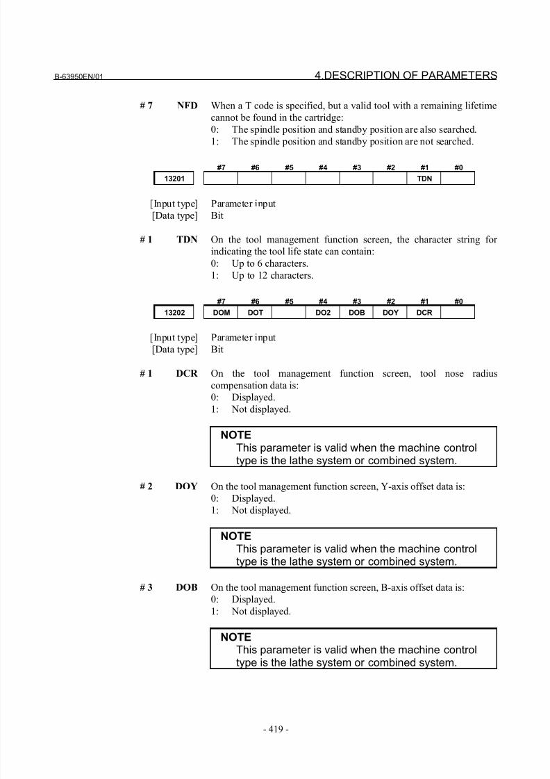
8/21/2019 30i Parameter Manual
http://slidepdf.com/reader/full/30i-parameter-manual 431/493
B-63950EN/01 4.DESCRIPTION OF PARAMETERS
- 419 -
# 7 NFD When a T code is specified, but a valid tool with a remaining lifetime
cannot be found in the cartridge:
0: The spindle position and standby position are also searched.
1: The spindle position and standby position are not searched.
#7 #6 #5 #4 #3 #2 #1 #0
13201 TDN
[Input type] Parameter input
[Data type] Bit
# 1 TDN On the tool management function screen, the character string for
indicating the tool life state can contain:
0: Up to 6 characters.
1: Up to 12 characters.
#7 #6 #5 #4 #3 #2 #1 #0
13202 DOM DOT DO2 DOB DOY DCR
[Input type] Parameter input
[Data type] Bit
# 1 DCR On the tool management function screen, tool nose radius
compensation data is:
0: Displayed.
1: Not displayed.
NOTEThis parameter is valid when the machine controltype is the lathe system or combined system.
# 2 DOY On the tool management function screen, Y-axis offset data is:
0: Displayed.
1: Not displayed.
NOTE
This parameter is valid when the machine controltype is the lathe system or combined system.
# 3 DOB On the tool management function screen, B-axis offset data is:
0: Displayed.
1: Not displayed.
NOTEThis parameter is valid when the machine controltype is the lathe system or combined system.
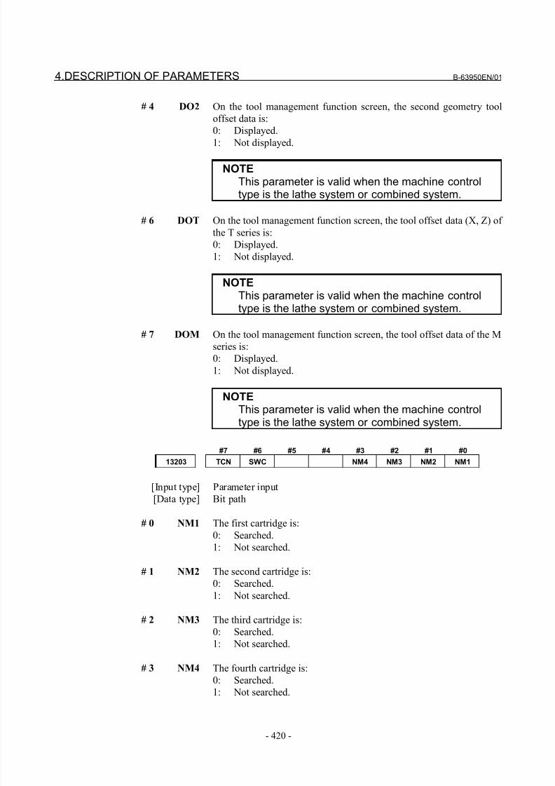
8/21/2019 30i Parameter Manual
http://slidepdf.com/reader/full/30i-parameter-manual 432/493
4.DESCRIPTION OF PARAMETERS B-63950EN/01
- 420 -
# 4 DO2 On the tool management function screen, the second geometry tool
offset data is:
0: Displayed.
1: Not displayed.
NOTEThis parameter is valid when the machine controltype is the lathe system or combined system.
# 6 DOT On the tool management function screen, the tool offset data (X, Z) of
the T series is:
0: Displayed.
1: Not displayed.
NOTEThis parameter is valid when the machine controltype is the lathe system or combined system.
# 7 DOM On the tool management function screen, the tool offset data of the M
series is:
0: Displayed.
1: Not displayed.
NOTE
This parameter is valid when the machine controltype is the lathe system or combined system.
#7 #6 #5 #4 #3 #2 #1 #0
13203 TCN SWC NM4 NM3 NM2 NM1
[Input type] Parameter input
[Data type] Bit path
# 0 NM1 The first cartridge is:
0: Searched.
1: Not searched.
# 1 NM2 The second cartridge is:
0: Searched.
1: Not searched.
# 2 NM3 The third cartridge is:
0: Searched.
1: Not searched.
# 3 NM4 The fourth cartridge is:
0: Searched.
1: Not searched.
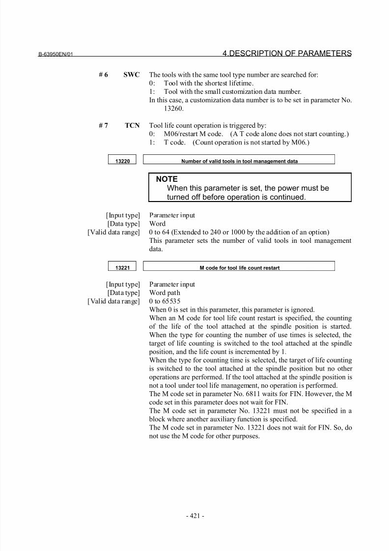
8/21/2019 30i Parameter Manual
http://slidepdf.com/reader/full/30i-parameter-manual 433/493
B-63950EN/01 4.DESCRIPTION OF PARAMETERS
- 421 -
# 6 SWC The tools with the same tool type number are searched for:
0: Tool with the shortest lifetime.
1: Tool with the small customization data number.
In this case, a customization data number is to be set in parameter No.
13260.
# 7 TCN Tool life count operation is triggered by:
0: M06/restart M code. (A T code alone does not start counting.)
1: T code. (Count operation is not started by M06.)
13220 Number of valid tools in tool management data
NOTEWhen this parameter is set, the power must beturned off before operation is continued.
[Input type] Parameter input
[Data type] Word
[Valid data range] 0 to 64 (Extended to 240 or 1000 by the addition of an option)
This parameter sets the number of valid tools in tool management
data.
13221 M code for tool life count restart
[Input type] Parameter input
[Data type] Word path
[Valid data range] 0 to 65535
When 0 is set in this parameter, this parameter is ignored.
When an M code for tool life count restart is specified, the counting
of the life of the tool attached at the spindle position is started.
When the type for counting the number of use times is selected, the
target of life counting is switched to the tool attached at the spindle
position, and the life count is incremented by 1.
When the type for counting time is selected, the target of life counting
is switched to the tool attached at the spindle position but no other
operations are performed. If the tool attached at the spindle position is
not a tool under tool life management, no operation is performed.The M code set in parameter No. 6811 waits for FIN. However, the M
code set in this parameter does not wait for FIN.
The M code set in parameter No. 13221 must not be specified in a
block where another auxiliary function is specified.
The M code set in parameter No. 13221 does not wait for FIN. So, do
not use the M code for other purposes.
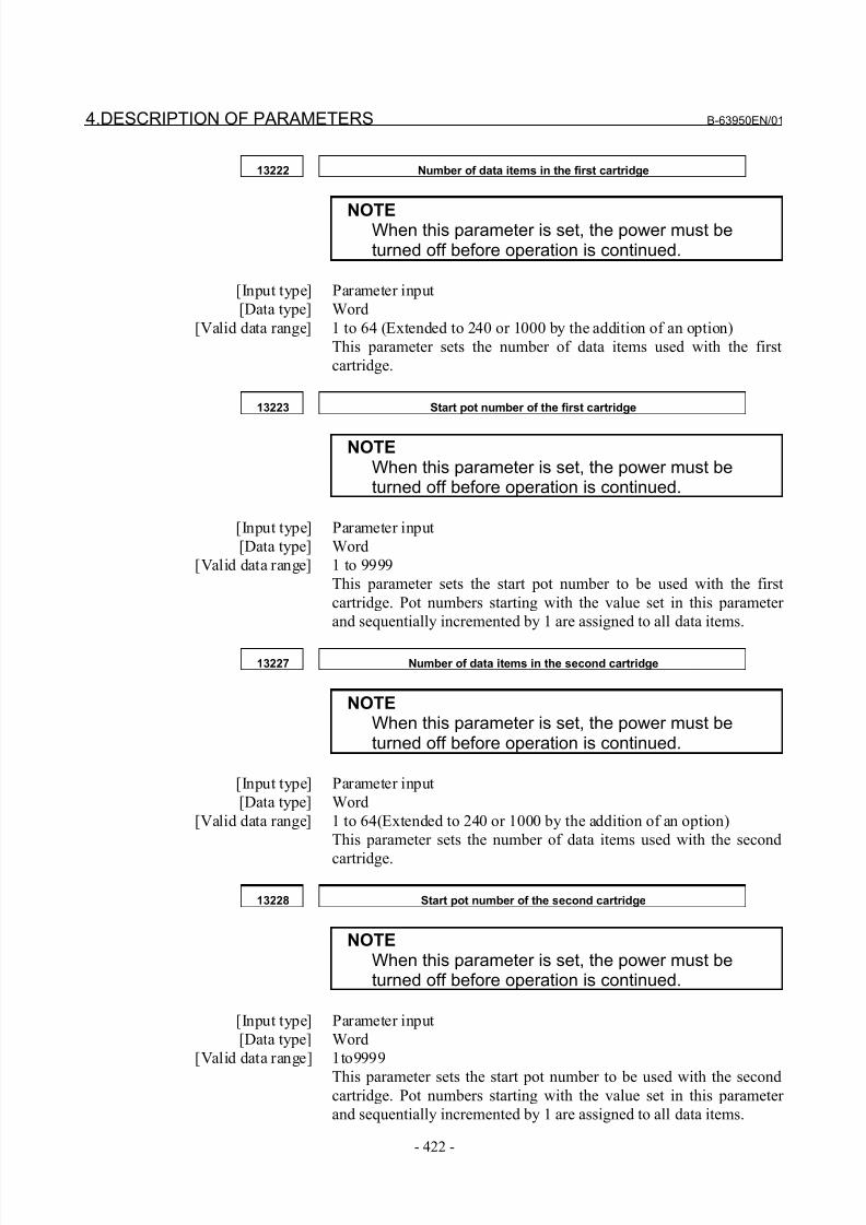
8/21/2019 30i Parameter Manual
http://slidepdf.com/reader/full/30i-parameter-manual 434/493
4.DESCRIPTION OF PARAMETERS B-63950EN/01
- 422 -
13222 Number of data items in the first cartridge
NOTEWhen this parameter is set, the power must beturned off before operation is continued.
[Input type] Parameter input
[Data type] Word
[Valid data range] 1 to 64 (Extended to 240 or 1000 by the addition of an option)
This parameter sets the number of data items used with the first
cartridge.
13223 Start pot number of the first cartridge
NOTEWhen this parameter is set, the power must beturned off before operation is continued.
[Input type] Parameter input
[Data type] Word
[Valid data range] 1 to 9999
This parameter sets the start pot number to be used with the first
cartridge. Pot numbers starting with the value set in this parameter
and sequentially incremented by 1 are assigned to all data items.
13227 Number of data items in the second cartridge
NOTEWhen this parameter is set, the power must beturned off before operation is continued.
[Input type] Parameter input
[Data type] Word
[Valid data range] 1 to 64(Extended to 240 or 1000 by the addition of an option)
This parameter sets the number of data items used with the second
cartridge.
13228 Start pot number of the second cartridge
NOTEWhen this parameter is set, the power must beturned off before operation is continued.
[Input type] Parameter input
[Data type] Word
[Valid data range] 1to9999
This parameter sets the start pot number to be used with the secondcartridge. Pot numbers starting with the value set in this parameter
and sequentially incremented by 1 are assigned to all data items.
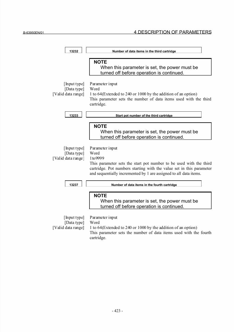
8/21/2019 30i Parameter Manual
http://slidepdf.com/reader/full/30i-parameter-manual 435/493
B-63950EN/01 4.DESCRIPTION OF PARAMETERS
- 423 -
13232 Number of data items in the third cartridge
NOTEWhen this parameter is set, the power must beturned off before operation is continued.
[Input type] Parameter input
[Data type] Word
[Valid data range] 1 to 64(Extended to 240 or 1000 by the addition of an option)
This parameter sets the number of data items used with the third
cartridge.
13233 Start pot number of the third cartridge
NOTEWhen this parameter is set, the power must beturned off before operation is continued.
[Input type] Parameter input
[Data type] Word
[Valid data range] 1to9999
This parameter sets the start pot number to be used with the third
cartridge. Pot numbers starting with the value set in this parameter
and sequentially incremented by 1 are assigned to all data items.
13237 Number of data items in the fourth cartridge
NOTEWhen this parameter is set, the power must beturned off before operation is continued.
[Input type] Parameter input
[Data type] Word
[Valid data range] 1 to 64(Extended to 240 or 1000 by the addition of an option)
This parameter sets the number of data items used with the fourthcartridge.
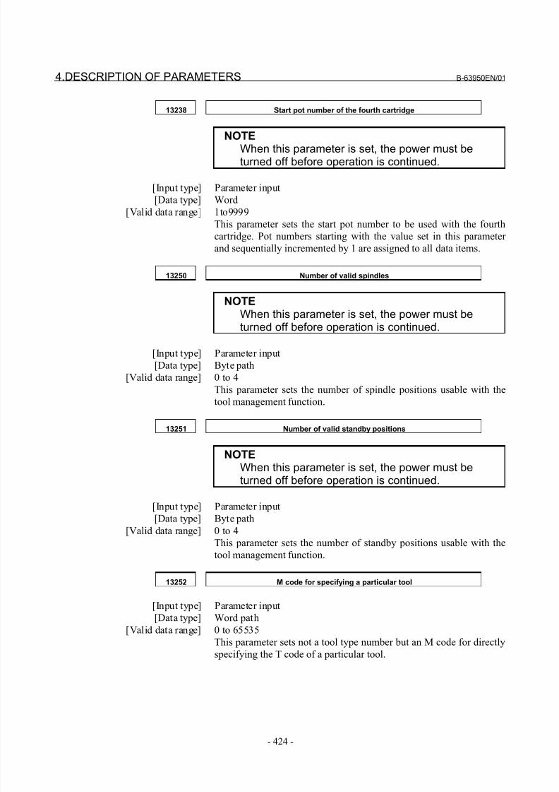
8/21/2019 30i Parameter Manual
http://slidepdf.com/reader/full/30i-parameter-manual 436/493
4.DESCRIPTION OF PARAMETERS B-63950EN/01
- 424 -
13238 Start pot number of the fourth cartridge
NOTEWhen this parameter is set, the power must beturned off before operation is continued.
[Input type] Parameter input
[Data type] Word
[Valid data range] 1to9999
This parameter sets the start pot number to be used with the fourth
cartridge. Pot numbers starting with the value set in this parameter
and sequentially incremented by 1 are assigned to all data items.
13250 Number of valid spindles
NOTEWhen this parameter is set, the power must beturned off before operation is continued.
[Input type] Parameter input
[Data type] Byte path
[Valid data range] 0 to 4
This parameter sets the number of spindle positions usable with the
tool management function.
13251 Number of valid standby positions
NOTEWhen this parameter is set, the power must beturned off before operation is continued.
[Input type] Parameter input
[Data type] Byte path
[Valid data range] 0 to 4
This parameter sets the number of standby positions usable with the
tool management function.
13252 M code for specifying a particular tool
[Input type] Parameter input
[Data type] Word path
[Valid data range] 0 to 65535
This parameter sets not a tool type number but an M code for directly
specifying the T code of a particular tool.
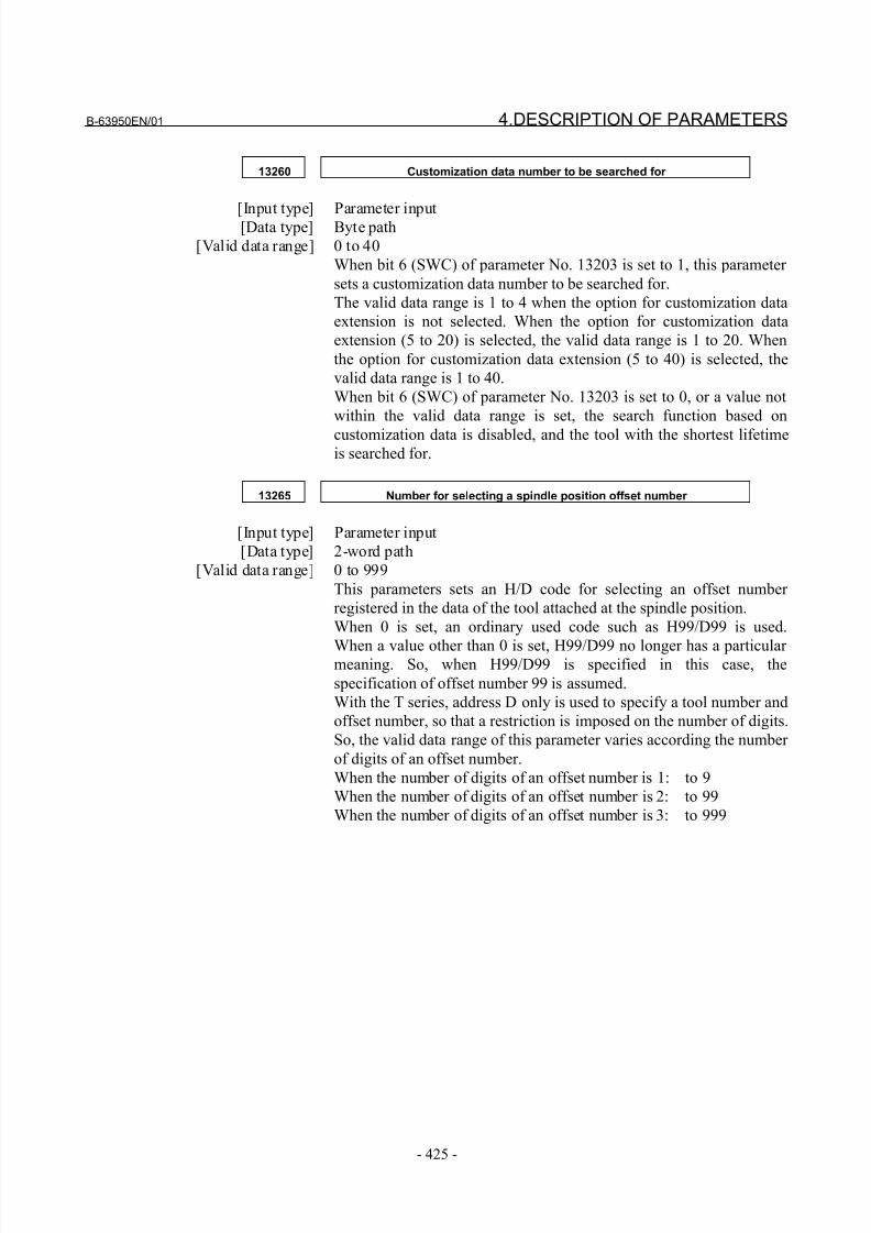
8/21/2019 30i Parameter Manual
http://slidepdf.com/reader/full/30i-parameter-manual 437/493
B-63950EN/01 4.DESCRIPTION OF PARAMETERS
- 425 -
13260 Customization data number to be searched for
[Input type] Parameter input[Data type] Byte path
[Valid data range] 0 to 40
When bit 6 (SWC) of parameter No. 13203 is set to 1, this parameter
sets a customization data number to be searched for.
The valid data range is 1 to 4 when the option for customization data
extension is not selected. When the option for customization data
extension (5 to 20) is selected, the valid data range is 1 to 20. When
the option for customization data extension (5 to 40) is selected, the
valid data range is 1 to 40.
When bit 6 (SWC) of parameter No. 13203 is set to 0, or a value not
within the valid data range is set, the search function based on
customization data is disabled, and the tool with the shortest lifetimeis searched for.
13265 Number for selecting a spindle position offset number
[Input type] Parameter input
[Data type] 2-word path
[Valid data range] 0 to 999
This parameters sets an H/D code for selecting an offset number
registered in the data of the tool attached at the spindle position.
When 0 is set, an ordinary used code such as H99/D99 is used.
When a value other than 0 is set, H99/D99 no longer has a particular meaning. So, when H99/D99 is specified in this case, the
specification of offset number 99 is assumed.
With the T series, address D only is used to specify a tool number and
offset number, so that a restriction is imposed on the number of digits.
So, the valid data range of this parameter varies according the number
of digits of an offset number.
When the number of digits of an offset number is 1: to 9
When the number of digits of an offset number is 2: to 99
When the number of digits of an offset number is 3: to 999
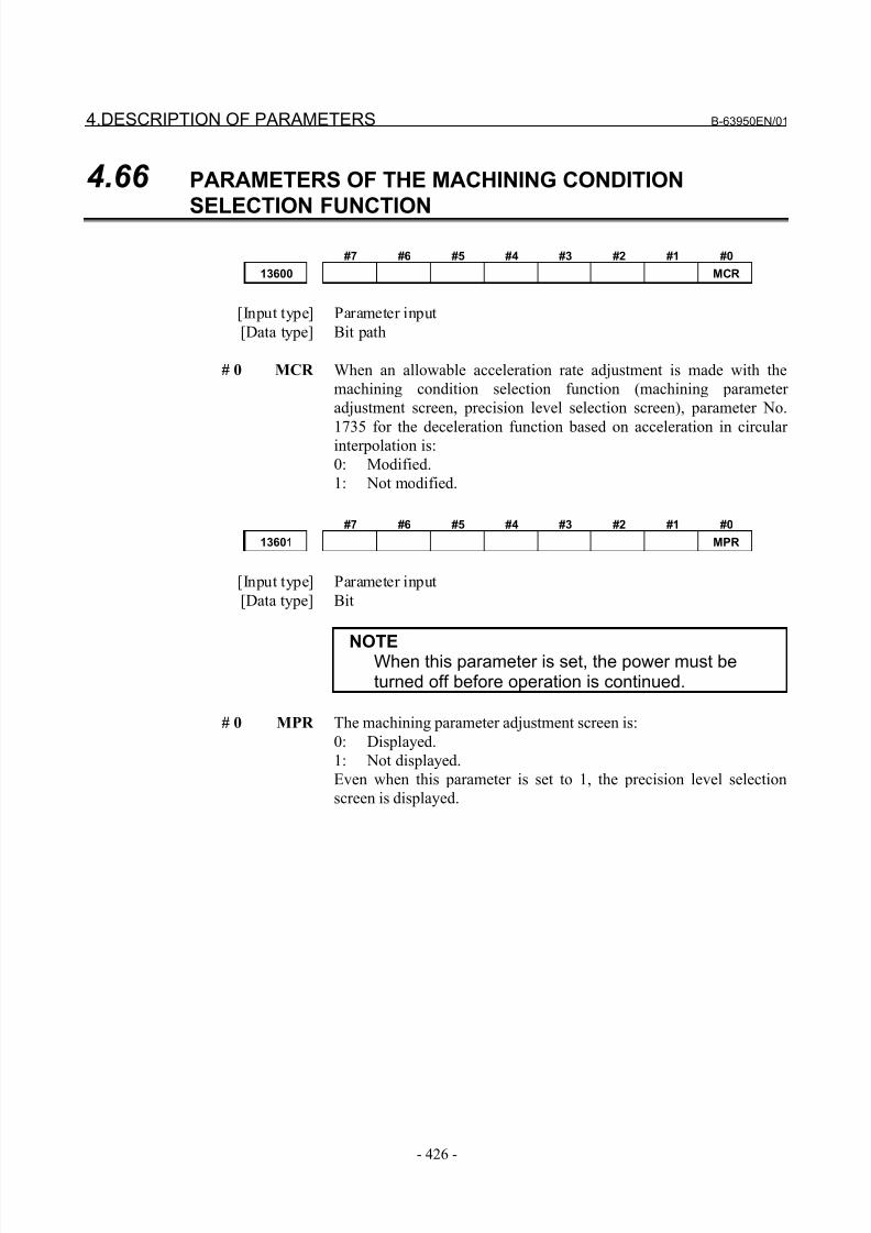
8/21/2019 30i Parameter Manual
http://slidepdf.com/reader/full/30i-parameter-manual 438/493
4.DESCRIPTION OF PARAMETERS B-63950EN/01
- 426 -
4.66 PARAMETERS OF THE MACHINING CONDITION
SELECTION FUNCTION
#7 #6 #5 #4 #3 #2 #1 #0
13600 MCR
[Input type] Parameter input
[Data type] Bit path
# 0 MCR When an allowable acceleration rate adjustment is made with the
machining condition selection function (machining parameter
adjustment screen, precision level selection screen), parameter No.
1735 for the deceleration function based on acceleration in circular interpolation is:
0: Modified.
1: Not modified.
#7 #6 #5 #4 #3 #2 #1 #0
13601 MPR
[Input type] Parameter input
[Data type] Bit
NOTEWhen this parameter is set, the power must beturned off before operation is continued.
# 0 MPR The machining parameter adjustment screen is:
0: Displayed.
1: Not displayed.
Even when this parameter is set to 1, the precision level selection
screen is displayed.
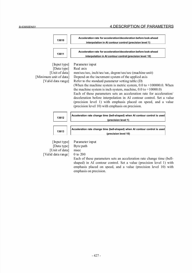
8/21/2019 30i Parameter Manual
http://slidepdf.com/reader/full/30i-parameter-manual 439/493
B-63950EN/01 4.DESCRIPTION OF PARAMETERS
- 427 -
13610Acceleration rate for acceleration/deceleration before look-ahead
interpolation in AI contour control (precision level 1)
13611Acceleration rate for acceleration/deceleration before look-ahead
interpolation in AI contour control (precision level 10)
[Input type] Parameter input
[Data type] Real axis
[Unit of data] mm/sec/sec, inch/sec/sec, degree/sec/sec (machine unit)
[Minimum unit of data] Depend on the increment system of the applied axis
[Valid data range] Refer to the standard parameter setting table (D)
(When the machine system is metric system, 0.0 to +100000.0. When
the machine system is inch system, machine, 0.0 to +10000.0)
Each of these parameters sets an acceleration rate for acceleration/
deceleration before interpolation in AI contour control. Set a value
(precision level 1) with emphasis placed on speed, and a value
(precision level 10) with emphasis on precision.
13612Acceleration rate change time (bell-shaped) when AI contour control is used
(precision level 1)
13613Acceleration rate change time (bell-shaped) when AI contour control is used
(precision level 10)
[Input type] Parameter input[Data type] Byte path
[Unit of data] msec
[Valid data range] 0 to 200
Each of these parameters sets an acceleration rate change time (bell-
shaped) in AI contour control. Set a value (precision level 1) with
emphasis placed on speed, and a value (precision level 10) with
emphasis on precision.
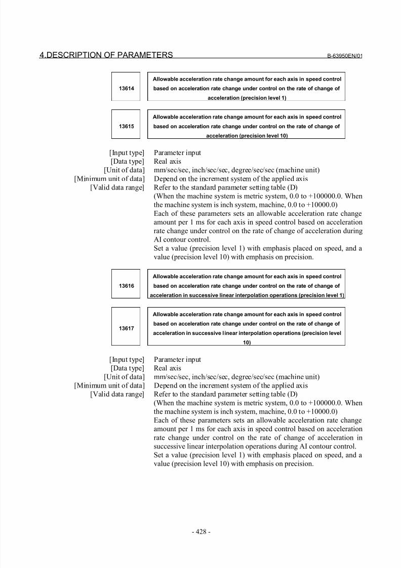
8/21/2019 30i Parameter Manual
http://slidepdf.com/reader/full/30i-parameter-manual 440/493
4.DESCRIPTION OF PARAMETERS B-63950EN/01
- 428 -
13614
Allowable acceleration rate change amount for each axis in speed control
based on acceleration rate change under control on the rate of change of
acceleration (precision level 1)
13615
Allowable acceleration rate change amount for each axis in speed control
based on acceleration rate change under control on the rate of change of
acceleration (precision level 10)
[Input type] Parameter input
[Data type] Real axis
[Unit of data] mm/sec/sec, inch/sec/sec, degree/sec/sec (machine unit)
[Minimum unit of data] Depend on the increment system of the applied axis
[Valid data range] Refer to the standard parameter setting table (D)
(When the machine system is metric system, 0.0 to +100000.0. Whenthe machine system is inch system, machine, 0.0 to +10000.0)
Each of these parameters sets an allowable acceleration rate change
amount per 1 ms for each axis in speed control based on acceleration
rate change under control on the rate of change of acceleration during
AI contour control.
Set a value (precision level 1) with emphasis placed on speed, and a
value (precision level 10) with emphasis on precision.
13616
Allowable acceleration rate change amount for each axis in speed control
based on acceleration rate change under control on the rate of change of
acceleration in successive linear interpolation operations (precision level 1)
13617
Allowable acceleration rate change amount for each axis in speed control
based on acceleration rate change under control on the rate of change of
acceleration in successive l inear interpolation operations (precision level
10)
[Input type] Parameter input
[Data type] Real axis
[Unit of data] mm/sec/sec, inch/sec/sec, degree/sec/sec (machine unit)
[Minimum unit of data] Depend on the increment system of the applied axis
[Valid data range] Refer to the standard parameter setting table (D)
(When the machine system is metric system, 0.0 to +100000.0. When
the machine system is inch system, machine, 0.0 to +10000.0)
Each of these parameters sets an allowable acceleration rate change
amount per 1 ms for each axis in speed control based on acceleration
rate change under control on the rate of change of acceleration in
successive linear interpolation operations during AI contour control.
Set a value (precision level 1) with emphasis placed on speed, and a
value (precision level 10) with emphasis on precision.
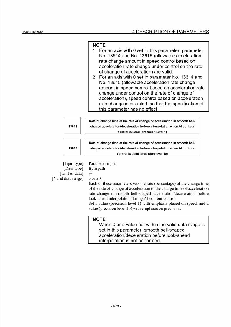
8/21/2019 30i Parameter Manual
http://slidepdf.com/reader/full/30i-parameter-manual 441/493
B-63950EN/01 4.DESCRIPTION OF PARAMETERS
- 429 -
NOTE1 For an axis with 0 set in this parameter, parameter
No. 13614 and No. 13615 (allowable accelerationrate change amount in speed control based onacceleration rate change under control on the rateof change of acceleration) are valid.
2 For an axis with 0 set in parameter No. 13614 andNo. 13615 (allowable acceleration rate changeamount in speed control based on acceleration ratechange under control on the rate of change of acceleration), speed control based on accelerationrate change is disabled, so that the specification of this parameter has no effect.
13618
Rate of change time of the rate of change of acceleration in smooth bell-
shaped acceleration/deceleration before interpolation when AI contour
control is used (precision level 1)
13619
Rate of change time of the rate of change of acceleration in smooth bell-
shaped acceleration/deceleration before interpolation when AI contour
control is used (precision level 10)
[Input type] Parameter input
[Data type] Byte path
[Unit of data] %[Valid data range] 0 to 50
Each of these parameters sets the rate (percentage) of the change time
of the rate of change of acceleration to the change time of acceleration
rate change in smooth bell-shaped acceleration/deceleration before
look-ahead interpolation during AI contour control.
Set a value (precision level 1) with emphasis placed on speed, and a
value (precision level 10) with emphasis on precision.
NOTEWhen 0 or a value not within the valid data range is
set in this parameter, smooth bell-shapedacceleration/deceleration before look-aheadinterpolation is not performed.
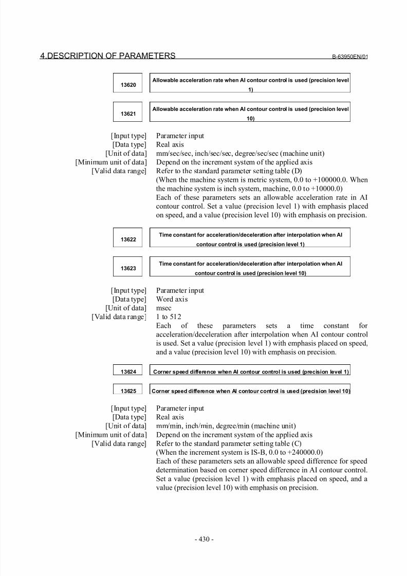
8/21/2019 30i Parameter Manual
http://slidepdf.com/reader/full/30i-parameter-manual 442/493
4.DESCRIPTION OF PARAMETERS B-63950EN/01
- 430 -
13620Allowable acceleration rate when AI contour control is used (precision level
1)
13621Allowable acceleration rate when AI contour control is used (precision level
10)
[Input type] Parameter input
[Data type] Real axis
[Unit of data] mm/sec/sec, inch/sec/sec, degree/sec/sec (machine unit)
[Minimum unit of data] Depend on the increment system of the applied axis
[Valid data range] Refer to the standard parameter setting table (D)
(When the machine system is metric system, 0.0 to +100000.0. When
the machine system is inch system, machine, 0.0 to +10000.0)
Each of these parameters sets an allowable acceleration rate in AI
contour control. Set a value (precision level 1) with emphasis placed
on speed, and a value (precision level 10) with emphasis on precision.
13622Time constant for acceleration/deceleration after interpolation when AI
contour control is used (precision level 1)
13623Time constant for acceleration/deceleration after interpolation when AI
contour control is used (precision level 10)
[Input type] Parameter input
[Data type] Word axis[Unit of data] msec
[Valid data range] 1 to 512
Each of these parameters sets a time constant for
acceleration/deceleration after interpolation when AI contour control
is used. Set a value (precision level 1) with emphasis placed on speed,
and a value (precision level 10) with emphasis on precision.
13624 Corner speed difference when AI contour control is used (precision level 1)
13625 Corner speed difference when AI contour control is used (precision level 10)
[Input type] Parameter input
[Data type] Real axis
[Unit of data] mm/min, inch/min, degree/min (machine unit)
[Minimum unit of data] Depend on the increment system of the applied axis
[Valid data range] Refer to the standard parameter setting table (C)
(When the increment system is IS-B, 0.0 to +240000.0)
Each of these parameters sets an allowable speed difference for speed
determination based on corner speed difference in AI contour control.
Set a value (precision level 1) with emphasis placed on speed, and a
value (precision level 10) with emphasis on precision.
8/21/2019 30i Parameter Manual
http://slidepdf.com/reader/full/30i-parameter-manual 443/493
B-63950EN/01 4.DESCRIPTION OF PARAMETERS
- 431 -
13626 Maximum cutting speed when AI contour control is used (precision level 1)
13627 Maximum cutting speed when AI contour control is used (precision level 10)
[Input type] Parameter input
[Data type] Real axis
[Unit of data] mm/min, inch/min, degree/min (machine unit)
[Minimum unit of data] Depend on the increment system of the applied axis
[Valid data range] Refer to the standard parameter setting table (C)
(When the increment system is IS-B, 0.0 to +240000.0)
Each of these parameters sets a maximum cutting speed in AI contour
control. Set a value (precision level 1) with emphasis placed on speed,
and a value (precision level 10) with emphasis on precision.
13628Parameter number corresponding to arbitrary item 1 when AI contour control
is used
13629Parameter number corresponding to arbitrary item 2 when AI contour control
is used
NOTEWhen this parameter is set, the power must beturned off before operation is continued.
[Input type] Parameter input[Data type] 2-word path
[Valid data range] 1 to 65535
These parameters set the parameter numbers corresponding to
arbitrary items 1 and 2.
NOTEThe parameter numbers corresponding to thefollowing cannot be specified:- Bit parameters- Spindle parameters (No. 4000 to No. 4799)
- Parameters of real number type- Parameters that require power-off (for which the
alarm (PW0000) is issued)- Nonexistent parameters
8/21/2019 30i Parameter Manual
http://slidepdf.com/reader/full/30i-parameter-manual 444/493
4.DESCRIPTION OF PARAMETERS B-63950EN/01
- 432 -
13630Value with emphasis on speed (precision level 1) of the parameter
corresponding to arbitrary item 1 when AI contour control is used
13631Value with emphasis on speed (precision level 1) of the parameter
corresponding to arbitrary item 2 when AI contour control is used
13632Value with emphasis on speed (precision level 10) of the parameter
corresponding to arbitrary item 1 when AI contour control is used
13633Value with emphasis on speed (precision level 10) of the parameter
corresponding to arbitrary item 2 when AI contour control is used
[Input type] Parameter input
[Data type] 2-word axis[Unit of data] Depend on the type of parameter for an arbitrary item
[Valid data range] Depend on the type of parameter for an arbitrary item
Each of these parameters sets a value with emphasis placed on speed
or precision for a parameter.
13634 Precision level currently selected when AI contour control is used
[Input type] Parameter input
[Data type] Byte path
[Valid data range] 1 to 10
This parameter sets the level currently selected.
8/21/2019 30i Parameter Manual
http://slidepdf.com/reader/full/30i-parameter-manual 445/493
B-63950EN/01 4.DESCRIPTION OF PARAMETERS
- 433 -
4.67 PARAMETERS OF FSSB
14340 ATR value corresponding to slave 01 on FSSB line 1
14341 ATR value corresponding to slave 02 on FSSB line 1
14342 ATR value corresponding to slave 03 on FSSB line 1
14343 ATR value corresponding to slave 04 on FSSB line 1
14344 ATR value corresponding to slave 05on FSSB line 1
14345 ATR value corresponding to slave 06 on FSSB line 1
14346 ATR value corresponding to slave 07 on FSSB line 1
14347 ATR value corresponding to slave 08 on FSSB line 1
14348 ATR value corresponding to slave 09 on FSSB line 1
14349 ATR value corresponding to slave 10 on FSSB line 1
14350 ATR value corresponding to slave 11 on FSSB line 1
14351 ATR value corresponding to slave 12 on FSSB line 1
14352 ATR value corresponding to slave 13 on FSSB line 1
14353 ATR value corresponding to slave 14 on FSSB line 1
14354 ATR value corresponding to slave 15 on FSSB line 1
14355 ATR value corresponding to slave 16 on FSSB line 1
14356 ATR value corresponding to slave 17 on FSSB line 1
14357 ATR value corresponding to slave 18 on FSSB line 1
NOTEWhen this parameter is set, the power must beturned off before operation is continued.
[Input type] Parameter input
[Data type] Byte[Valid data range] 0to23,64,-56,-96
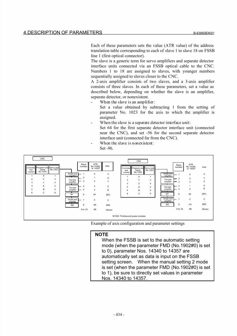
8/21/2019 30i Parameter Manual
http://slidepdf.com/reader/full/30i-parameter-manual 446/493
4.DESCRIPTION OF PARAMETERS B-63950EN/01
- 434 -
Each of these parameters sets the value (ATR value) of the address
translation table corresponding to each of slave 1 to slave 18 on FSSB
line 1 (first optical connector).
The slave is a generic term for servo amplifiers and separate detector
interface units connected via an FSSB optical cable to the CNC.
Numbers 1 to 18 are assigned to slaves, with younger numbers
sequentially assigned to slaves closer to the CNC.
A 2-axis amplifier consists of two slaves, and a 3-axis amplifier
consists of three slaves. In each of these parameters, set a value as
described below, depending on whether the slave is an amplifier,
separate detector, or nonexistent.
- When the slave is an amplifier:
Set a value obtained by subtracting 1 from the setting of
parameter No. 1023 for the axis to which the amplifier is
assigned.- When the slave is a separate detector interface unit:
Set 64 for the first separate detector interface unit (connected
near the CNC), and set -56 for the second separate detector
interface unit (connected far from the CNC).
- When the slave is nonexistent:
Set -96.
1 0
2 1
3 2
4 3
5 4
6 64
7 5
8 -56
9 to 18 -96
Slavenumber
ATRNo.14340 to 14357
X
A
Y
Z
B
(M1)
C
(M2)
(None)
Axis
1 X 12 Y 3
3 Z 4
4 A 2
5 B 5
6 C 6
Controlledaxis
number
Program axisname
No.1020
Servo axisNo.1023
CNC
Two-axisamplifier
Single-axis
amplifier
M1
Two-axisamplifier
Single-axisamplifier
M2
M1/M2: First/second pulse modules
1 0
2 2
3 3
4 1
5 4
6 64
7 5
8 -56
9 to 18 -96
Slavenumber
X
Y
Z
A
B
(M1)
C
(M2)
(None)
Axis
1 X 1
2 Y 3
3 Z 4
4 A 2
5 B 5
6 C 6
Controlledaxis
number
Program axisname
No.1020
Servo axisNo.1023
CNC
Two-axisamplifier
Single-axis
amplifier
M1
Two-axisamplifier
Single-axisamplifier
M2
ATRNo.14340 to 14357
Example of axis configuration and parameter settings
NOTEWhen the FSSB is set to the automatic settingmode (when the parameter FMD (No.1902#0) is setto 0), parameter Nos. 14340 to 14357 areautomatically set as data is input on the FSSBsetting screen. When the manual setting 2 modeis set (when the parameter FMD (No.1902#0) is setto 1), be sure to directly set values in parameter Nos. 14340 to 14357.
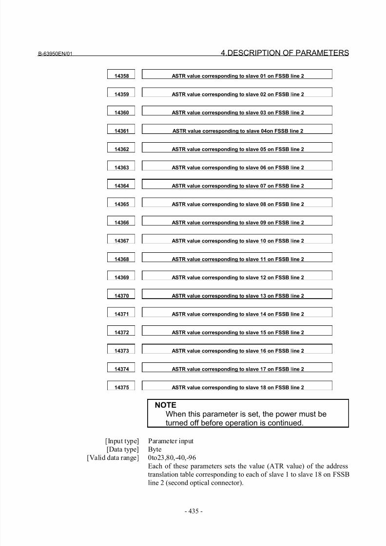
8/21/2019 30i Parameter Manual
http://slidepdf.com/reader/full/30i-parameter-manual 447/493
B-63950EN/01 4.DESCRIPTION OF PARAMETERS
- 435 -
14358 ASTR value corresponding to slave 01 on FSSB line 2
14359 ASTR value corresponding to slave 02 on FSSB line 2
14360 ASTR value corresponding to slave 03 on FSSB line 2
14361 ASTR value corresponding to slave 04on FSSB line 2
14362 ASTR value corresponding to slave 05 on FSSB line 2
14363 ASTR value corresponding to slave 06 on FSSB line 2
14364 ASTR value corresponding to slave 07 on FSSB line 2
14365 ASTR value corresponding to slave 08 on FSSB line 2
14366 ASTR value corresponding to slave 09 on FSSB line 2
14367 ASTR value corresponding to slave 10 on FSSB line 2
14368 ASTR value corresponding to slave 11 on FSSB line 2
14369 ASTR value corresponding to slave 12 on FSSB line 2
14370 ASTR value corresponding to slave 13 on FSSB line 2
14371 ASTR value corresponding to slave 14 on FSSB line 2
14372 ASTR value corresponding to slave 15 on FSSB line 2
14373 ASTR value corresponding to slave 16 on FSSB line 2
14374 ASTR value corresponding to slave 17 on FSSB line 2
14375 ASTR value corresponding to slave 18 on FSSB line 2
NOTEWhen this parameter is set, the power must beturned off before operation is continued.
[Input type] Parameter input
[Data type] Byte
[Valid data range] 0to23,80,-40,-96
Each of these parameters sets the value (ATR value) of the address
translation table corresponding to each of slave 1 to slave 18 on FSSB
line 2 (second optical connector).
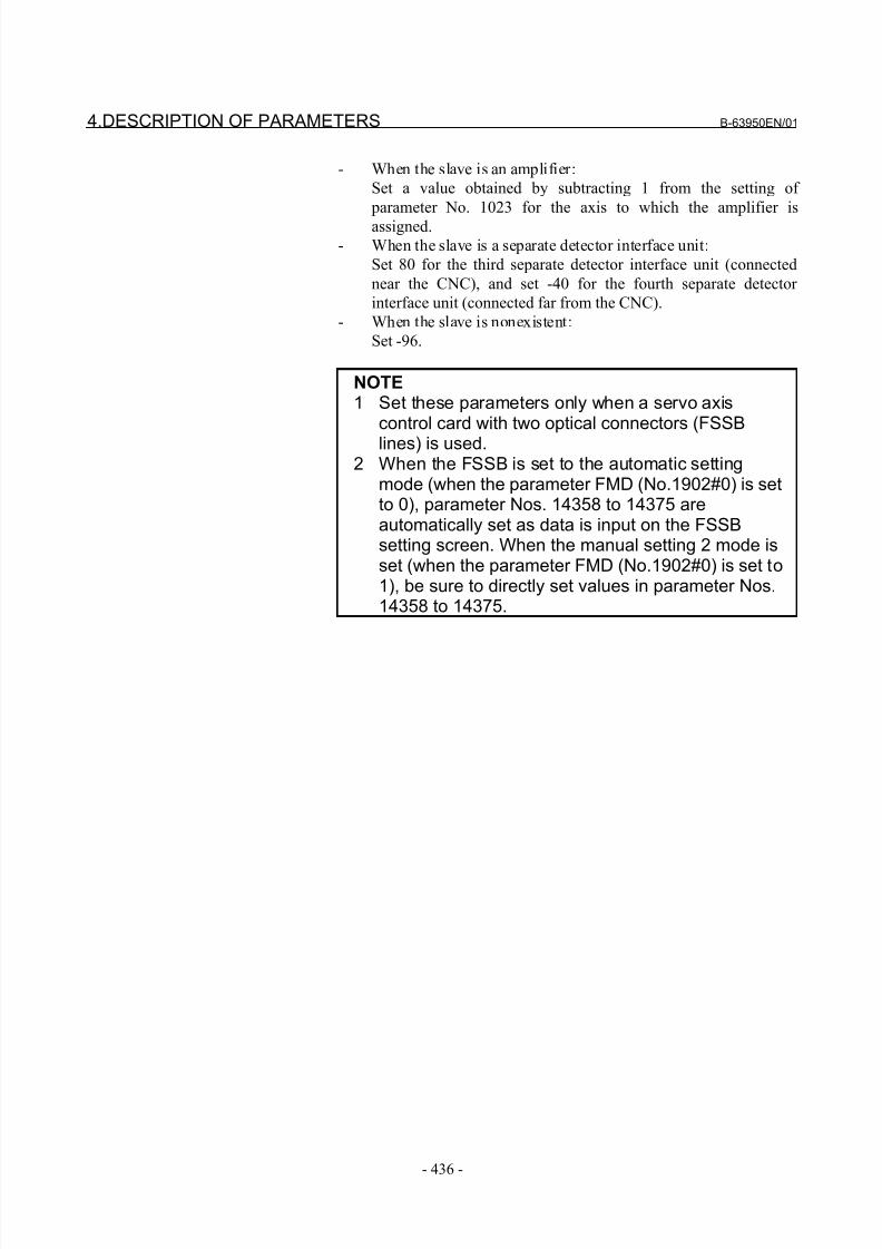
8/21/2019 30i Parameter Manual
http://slidepdf.com/reader/full/30i-parameter-manual 448/493
4.DESCRIPTION OF PARAMETERS B-63950EN/01
- 436 -
- When the slave is an amplifier:
Set a value obtained by subtracting 1 from the setting of
parameter No. 1023 for the axis to which the amplifier is
assigned.
- When the slave is a separate detector interface unit:
Set 80 for the third separate detector interface unit (connected
near the CNC), and set -40 for the fourth separate detector
interface unit (connected far from the CNC).
- When the slave is nonexistent:
Set -96.
NOTE1 Set these parameters only when a servo axis
control card with two optical connectors (FSSB
lines) is used.2 When the FSSB is set to the automatic setting
mode (when the parameter FMD (No.1902#0) is setto 0), parameter Nos. 14358 to 14375 areautomatically set as data is input on the FSSBsetting screen. When the manual setting 2 mode isset (when the parameter FMD (No.1902#0) is set to1), be sure to directly set values in parameter Nos.14358 to 14375.
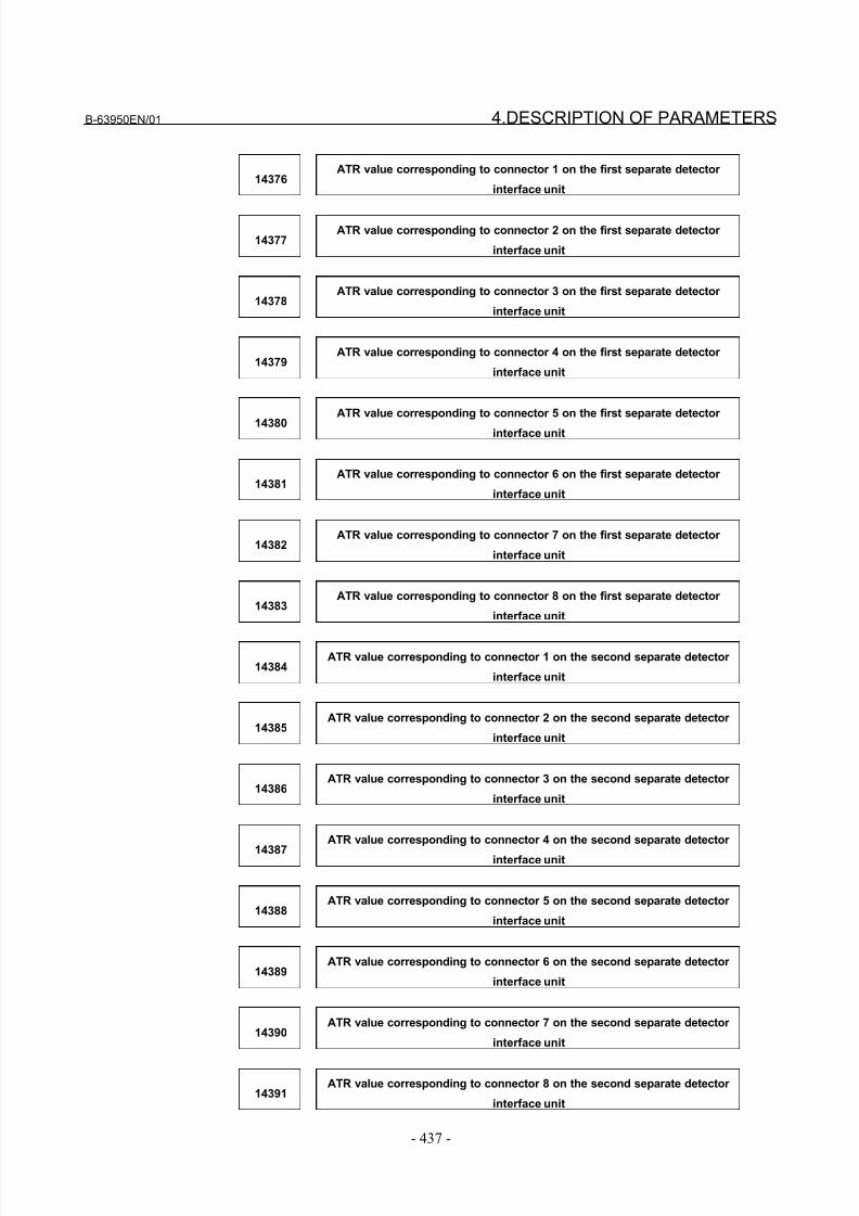
8/21/2019 30i Parameter Manual
http://slidepdf.com/reader/full/30i-parameter-manual 449/493
B-63950EN/01 4.DESCRIPTION OF PARAMETERS
- 437 -
14376ATR value corresponding to connector 1 on the first separate detector
interface unit
14377ATR value corresponding to connector 2 on the first separate detector
interface unit
14378ATR value corresponding to connector 3 on the first separate detector
interface unit
14379ATR value corresponding to connector 4 on the first separate detector
interface unit
14380
ATR value corresponding to connector 5 on the first separate detector
interface unit
14381ATR value corresponding to connector 6 on the first separate detector
interface unit
14382ATR value corresponding to connector 7 on the first separate detector
interface unit
14383ATR value corresponding to connector 8 on the first separate detector
interface unit
14384ATR value corresponding to connector 1 on the second separate detector
interface unit
14385ATR value corresponding to connector 2 on the second separate detector
interface unit
14386ATR value corresponding to connector 3 on the second separate detector
interface unit
14387
ATR value corresponding to connector 4 on the second separate detector
interface unit
14388ATR value corresponding to connector 5 on the second separate detector
interface unit
14389ATR value corresponding to connector 6 on the second separate detector
interface unit
14390ATR value corresponding to connector 7 on the second separate detector
interface unit
14391ATR value corresponding to connector 8 on the second separate detector
interface unit
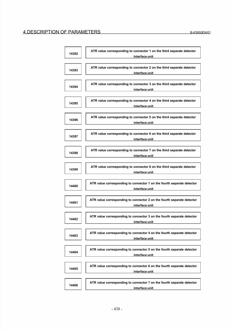
8/21/2019 30i Parameter Manual
http://slidepdf.com/reader/full/30i-parameter-manual 450/493
4.DESCRIPTION OF PARAMETERS B-63950EN/01
- 438 -
14392ATR value corresponding to connector 1 on the third separate detector
interface unit
14393ATR value corresponding to connector 2 on the third separate detector
interface unit
14394ATR value corresponding to connector 3 on the third separate detector
interface unit
14395ATR value corresponding to connector 4 on the third separate detector
interface unit
14396ATR value corresponding to connector 5 on the third separate detector
interface unit
14397ATR value corresponding to connector 6 on the third separate detector
interface unit
14398ATR value corresponding to connector 7 on the third separate detector
interface unit
14399ATR value corresponding to connector 8 on the third separate detector
interface unit
14400ATR value corresponding to connector 1 on the fourth separate detector
interface unit
14401ATR value corresponding to connector 2 on the fourth separate detector
interface unit
14402ATR value corresponding to connector 3 on the fourth separate detector
interface unit
14403ATR value corresponding to connector 4 on the fourth separate detector
interface unit
14404ATR value corresponding to connector 5 on the fourth separate detector
interface unit
14405ATR value corresponding to connector 6 on the fourth separate detector
interface unit
14406ATR value corresponding to connector 7 on the fourth separate detector
interface unit
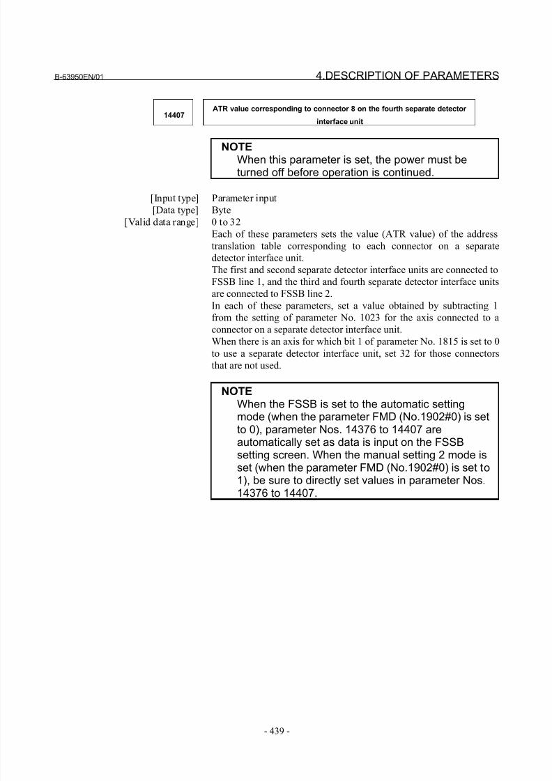
8/21/2019 30i Parameter Manual
http://slidepdf.com/reader/full/30i-parameter-manual 451/493
B-63950EN/01 4.DESCRIPTION OF PARAMETERS
- 439 -
14407ATR value corresponding to connector 8 on the fourth separate detector
interface unit
NOTEWhen this parameter is set, the power must beturned off before operation is continued.
[Input type] Parameter input
[Data type] Byte
[Valid data range] 0 to 32
Each of these parameters sets the value (ATR value) of the address
translation table corresponding to each connector on a separate
detector interface unit.
The first and second separate detector interface units are connected toFSSB line 1, and the third and fourth separate detector interface units
are connected to FSSB line 2.
In each of these parameters, set a value obtained by subtracting 1
from the setting of parameter No. 1023 for the axis connected to a
connector on a separate detector interface unit.
When there is an axis for which bit 1 of parameter No. 1815 is set to 0
to use a separate detector interface unit, set 32 for those connectors
that are not used.
NOTEWhen the FSSB is set to the automatic settingmode (when the parameter FMD (No.1902#0) is setto 0), parameter Nos. 14376 to 14407 areautomatically set as data is input on the FSSBsetting screen. When the manual setting 2 mode isset (when the parameter FMD (No.1902#0) is set to1), be sure to directly set values in parameter Nos.14376 to 14407.
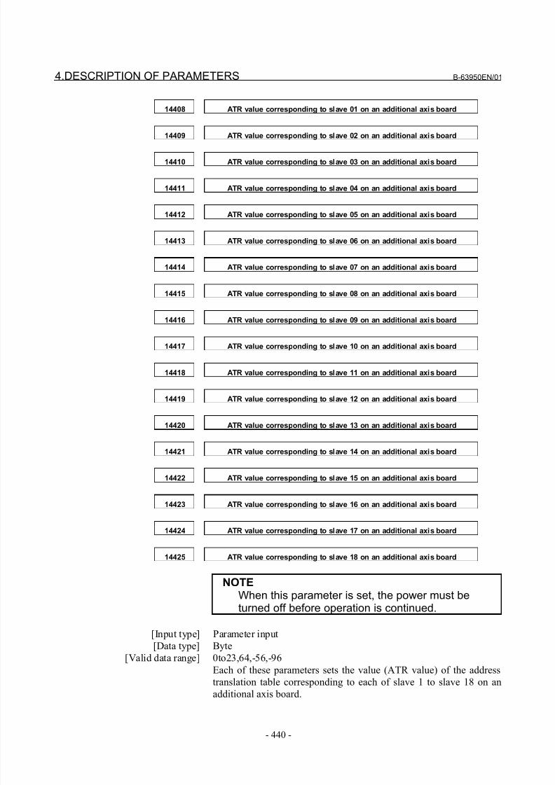
8/21/2019 30i Parameter Manual
http://slidepdf.com/reader/full/30i-parameter-manual 452/493
4.DESCRIPTION OF PARAMETERS B-63950EN/01
- 440 -
14408 ATR value corresponding to slave 01 on an additional axis board
14409 ATR value corresponding to slave 02 on an additional axis board
14410 ATR value corresponding to slave 03 on an additional axis board
14411 ATR value corresponding to slave 04 on an additional axis board
14412 ATR value corresponding to slave 05 on an additional axis board
14413 ATR value corresponding to slave 06 on an additional axis board
14414 ATR value corresponding to slave 07 on an additional axis board
14415 ATR value corresponding to slave 08 on an additional axis board
14416 ATR value corresponding to slave 09 on an additional axis board
14417 ATR value corresponding to slave 10 on an additional axis board
14418 ATR value corresponding to slave 11 on an additional axis board
14419 ATR value corresponding to slave 12 on an additional axis board
14420 ATR value corresponding to slave 13 on an additional axis board
14421 ATR value corresponding to slave 14 on an additional axis board
14422 ATR value corresponding to slave 15 on an additional axis board
14423 ATR value corresponding to slave 16 on an additional axis board
14424 ATR value corresponding to slave 17 on an additional axis board
14425 ATR value corresponding to slave 18 on an additional axis board
NOTEWhen this parameter is set, the power must beturned off before operation is continued.
[Input type] Parameter input
[Data type] Byte
[Valid data range] 0to23,64,-56,-96
Each of these parameters sets the value (ATR value) of the address
translation table corresponding to each of slave 1 to slave 18 on an
additional axis board.
8/21/2019 30i Parameter Manual
http://slidepdf.com/reader/full/30i-parameter-manual 453/493
B-63950EN/01 4.DESCRIPTION OF PARAMETERS
- 441 -
- When the slave is an amplifier:
Set a value obtained by subtracting 25 from the setting of
parameter No. 1023 for the axis to which the amplifier is
assigned.
- When the slave is a separate detector interface unit:
Set 64 for the first separate detector interface unit (connected
near the CNC), and set -56 for the second separate detector
interface unit (connected far from the CNC).
- When the slave is nonexistent:
Set -96.
NOTE1 Set these parameters when using an additional axis
board.
2 When the FSSB is set to the automatic settingmode (when the parameter FMD (No.1902#0) is setto 0), parameter Nos. 14408 to 14425 areautomatically set as data is input on the FSSBsetting screen. When the manual setting 2 mode isset (when the parameter FMD (No.1902#0) is set to1), be sure to directly set values in parameter Nos.14408 to 14425.
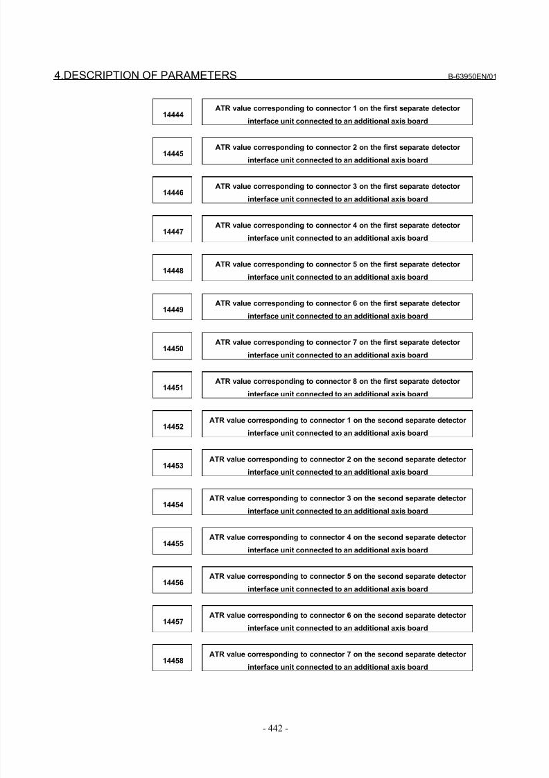
8/21/2019 30i Parameter Manual
http://slidepdf.com/reader/full/30i-parameter-manual 454/493
4.DESCRIPTION OF PARAMETERS B-63950EN/01
- 442 -
14444ATR value corresponding to connector 1 on the first separate detector
interface unit connected to an additional axis board
14445ATR value corresponding to connector 2 on the first separate detector
interface unit connected to an additional axis board
14446ATR value corresponding to connector 3 on the first separate detector
interface unit connected to an additional axis board
14447ATR value corresponding to connector 4 on the first separate detector
interface unit connected to an additional axis board
14448
ATR value corresponding to connector 5 on the first separate detector
interface unit connected to an additional axis board
14449ATR value corresponding to connector 6 on the first separate detector
interface unit connected to an additional axis board
14450ATR value corresponding to connector 7 on the first separate detector
interface unit connected to an additional axis board
14451ATR value corresponding to connector 8 on the first separate detector
interface unit connected to an additional axis board
14452ATR value corresponding to connector 1 on the second separate detector
interface unit connected to an additional axis board
14453ATR value corresponding to connector 2 on the second separate detector
interface unit connected to an additional axis board
14454ATR value corresponding to connector 3 on the second separate detector
interface unit connected to an additional axis board
14455
ATR value corresponding to connector 4 on the second separate detector
interface unit connected to an additional axis board
14456ATR value corresponding to connector 5 on the second separate detector
interface unit connected to an additional axis board
14457ATR value corresponding to connector 6 on the second separate detector
interface unit connected to an additional axis board
14458ATR value corresponding to connector 7 on the second separate detector
interface unit connected to an additional axis board
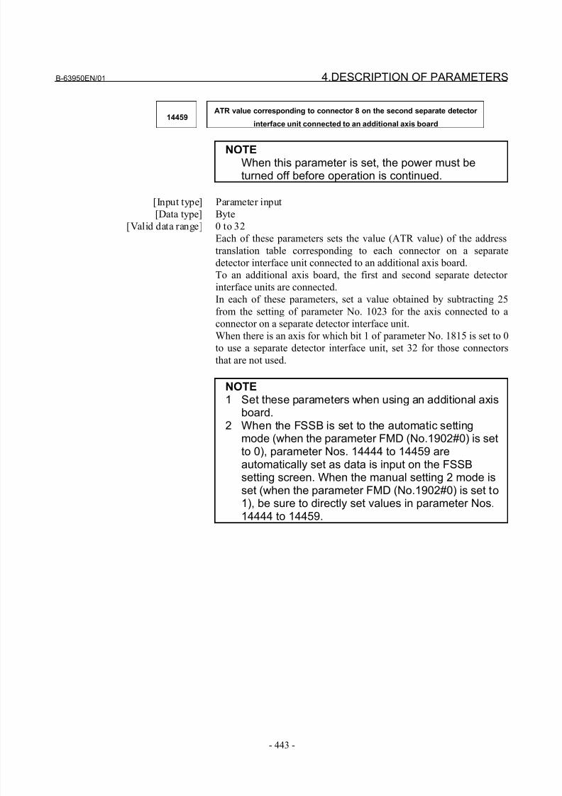
8/21/2019 30i Parameter Manual
http://slidepdf.com/reader/full/30i-parameter-manual 455/493
B-63950EN/01 4.DESCRIPTION OF PARAMETERS
- 443 -
14459ATR value corresponding to connector 8 on the second separate detector
interface unit connected to an additional axis board
NOTEWhen this parameter is set, the power must beturned off before operation is continued.
[Input type] Parameter input
[Data type] Byte
[Valid data range] 0 to 32
Each of these parameters sets the value (ATR value) of the address
translation table corresponding to each connector on a separate
detector interface unit connected to an additional axis board.
To an additional axis board, the first and second separate detector interface units are connected.
In each of these parameters, set a value obtained by subtracting 25
from the setting of parameter No. 1023 for the axis connected to a
connector on a separate detector interface unit.
When there is an axis for which bit 1 of parameter No. 1815 is set to 0
to use a separate detector interface unit, set 32 for those connectors
that are not used.
NOTE1 Set these parameters when using an additional axis
board.2 When the FSSB is set to the automatic settingmode (when the parameter FMD (No.1902#0) is setto 0), parameter Nos. 14444 to 14459 areautomatically set as data is input on the FSSBsetting screen. When the manual setting 2 mode isset (when the parameter FMD (No.1902#0) is set to1), be sure to directly set values in parameter Nos.14444 to 14459.
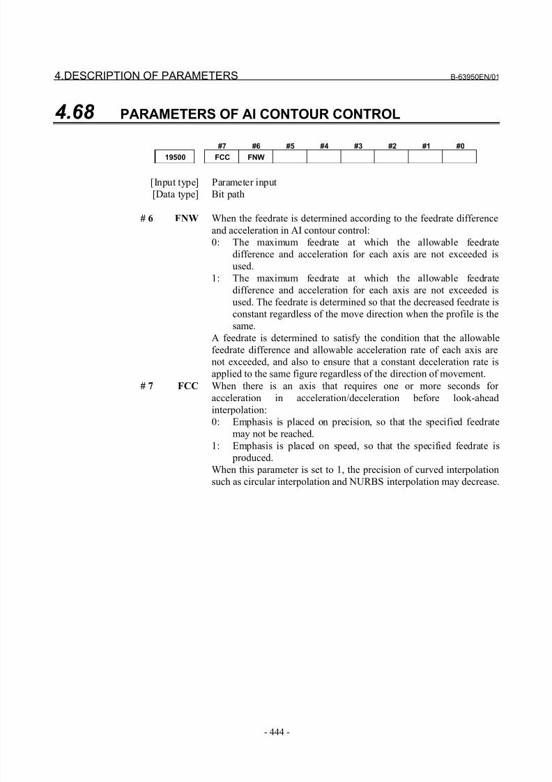
8/21/2019 30i Parameter Manual
http://slidepdf.com/reader/full/30i-parameter-manual 456/493
4.DESCRIPTION OF PARAMETERS B-63950EN/01
- 444 -
4.68 PARAMETERS OF AI CONTOUR CONTROL
#7 #6 #5 #4 #3 #2 #1 #0
19500 FCC FNW
[Input type] Parameter input
[Data type] Bit path
# 6 FNW When the feedrate is determined according to the feedrate difference
and acceleration in AI contour control:
0: The maximum feedrate at which the allowable feedrate
difference and acceleration for each axis are not exceeded is
used.
1: The maximum feedrate at which the allowable feedrate
difference and acceleration for each axis are not exceeded is
used. The feedrate is determined so that the decreased feedrate is
constant regardless of the move direction when the profile is the
same.
A feedrate is determined to satisfy the condition that the allowable
feedrate difference and allowable acceleration rate of each axis are
not exceeded, and also to ensure that a constant deceleration rate is
applied to the same figure regardless of the direction of movement.
# 7 FCC When there is an axis that requires one or more seconds for
acceleration in acceleration/deceleration before look-ahead
interpolation:0: Emphasis is placed on precision, so that the specified feedrate
may not be reached.
1: Emphasis is placed on speed, so that the specified feedrate is
produced.
When this parameter is set to 1, the precision of curved interpolation
such as circular interpolation and NURBS interpolation may decrease.
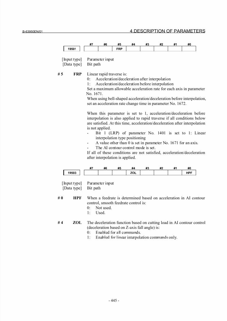
8/21/2019 30i Parameter Manual
http://slidepdf.com/reader/full/30i-parameter-manual 457/493
B-63950EN/01 4.DESCRIPTION OF PARAMETERS
- 445 -
#7 #6 #5 #4 #3 #2 #1 #0
19501 FRP
[Input type] Parameter input
[Data type] Bit path
# 5 FRP Linear rapid traverse is:
0: Acceleration/deceleration after interpolation
1: Acceleration/deceleration before interpolation
Set a maximum allowable acceleration rate for each axis in parameter
No. 1671.
When using bell-shaped acceleration/deceleration before interpolation,
set an acceleration rate change time in parameter No. 1672.
When this parameter is set to 1, acceleration/deceleration beforeinterpolation is also applied to rapid traverse if all conditions below
are satisfied. At this time, acceleration/deceleration after interpolation
is not applied.
- Bit 1 (LRP) of parameter No. 1401 is set to 1: Linear
interpolation type positioning
- A value other than 0 is set in parameter No. 1671 for an axis.
- The AI contour control mode is set.
If all of these conditions are not satisfied, acceleration/deceleration
after interpolation is applied.
#7 #6 #5 #4 #3 #2 #1 #019503 ZOL HPF
[Input type] Parameter input
[Data type] Bit path
# 0 HPF When a feedrate is determined based on acceleration in AI contour
control, smooth feedrate control is:
0: Not used.
1: Used.
# 4 ZOL The deceleration function based on cutting load in AI contour control
(deceleration based on Z-axis fall angle) is:
0: Enabled for all commands.
1: Enabled for linear interpolation commands only.
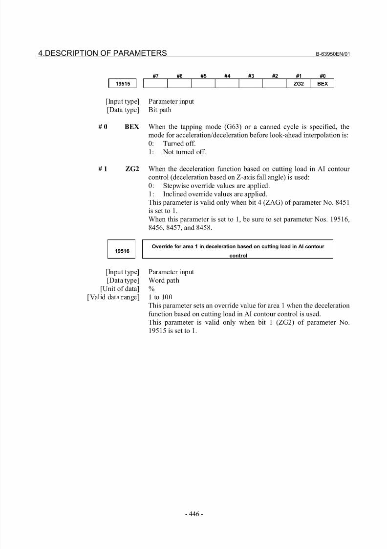
8/21/2019 30i Parameter Manual
http://slidepdf.com/reader/full/30i-parameter-manual 458/493
4.DESCRIPTION OF PARAMETERS B-63950EN/01
- 446 -
#7 #6 #5 #4 #3 #2 #1 #0
19515 ZG2 BEX
[Input type] Parameter input
[Data type] Bit path
# 0 BEX When the tapping mode (G63) or a canned cycle is specified, the
mode for acceleration/deceleration before look-ahead interpolation is:
0: Turned off.
1: Not turned off.
# 1 ZG2 When the deceleration function based on cutting load in AI contour
control (deceleration based on Z-axis fall angle) is used:
0: Stepwise override values are applied.
1: Inclined override values are applied.This parameter is valid only when bit 4 (ZAG) of parameter No. 8451
is set to 1.
When this parameter is set to 1, be sure to set parameter Nos. 19516,
8456, 8457, and 8458.
19516Override for area 1 in deceleration based on cutting load in AI contour
control
[Input type] Parameter input
[Data type] Word path
[Unit of data] %[Valid data range] 1 to 100
This parameter sets an override value for area 1 when the deceleration
function based on cutting load in AI contour control is used.
This parameter is valid only when bit 1 (ZG2) of parameter No.
19515 is set to 1.
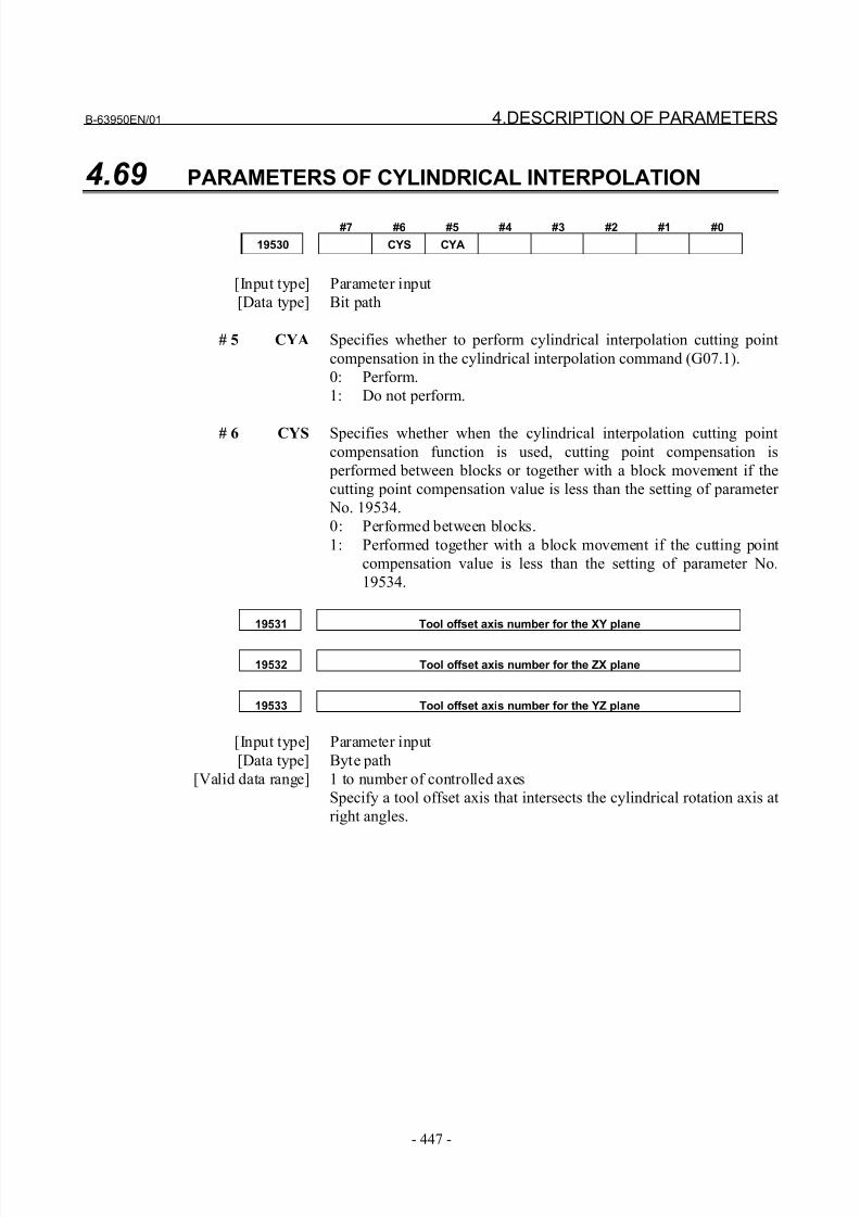
8/21/2019 30i Parameter Manual
http://slidepdf.com/reader/full/30i-parameter-manual 459/493
B-63950EN/01 4.DESCRIPTION OF PARAMETERS
- 447 -
4.69 PARAMETERS OF CYLINDRICAL INTERPOLATION
#7 #6 #5 #4 #3 #2 #1 #0
19530 CYS CYA
[Input type] Parameter input
[Data type] Bit path
# 5 CYA Specifies whether to perform cylindrical interpolation cutting point
compensation in the cylindrical interpolation command (G07.1).
0: Perform.
1: Do not perform.
# 6 CYS Specifies whether when the cylindrical interpolation cutting point
compensation function is used, cutting point compensation is
performed between blocks or together with a block movement if the
cutting point compensation value is less than the setting of parameter
No. 19534.
0: Performed between blocks.
1: Performed together with a block movement if the cutting point
compensation value is less than the setting of parameter No.
19534.
19531 Tool offset axis number for the XY plane
19532 Tool offset axis number for the ZX plane
19533 Tool offset axis number for the YZ plane
[Input type] Parameter input
[Data type] Byte path
[Valid data range] 1 to number of controlled axes
Specify a tool offset axis that intersects the cylindrical rotation axis at
right angles.
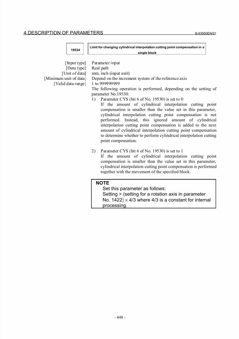
8/21/2019 30i Parameter Manual
http://slidepdf.com/reader/full/30i-parameter-manual 460/493
4.DESCRIPTION OF PARAMETERS B-63950EN/01
- 448 -
19534Limit for changing cylindrical interpolation cutting point compensation in a
single block
[Input type] Parameter input
[Data type] Real path
[Unit of data] mm, inch (input unit)
[Minimum unit of data] Depend on the increment system of the reference axis
[Valid data range] 1 to 999999999
The following operation is performed, depending on the setting of
parameter No.19530:
1) Parameter CYS (bit 6 of No. 19530) is set to 0
If the amount of cylindrical interpolation cutting point
compensation is smaller than the value set in this parameter,
cylindrical interpolation cutting point compensation is not
performed. Instead, this ignored amount of cylindricalinterpolation cutting point compensation is added to the next
amount of cylindrical interpolation cutting point compensation
to determine whether to perform cylindrical interpolation cutting
point compensation.
2) Parameter CYS (bit 6 of No. 19530) is set to 1
If the amount of cylindrical interpolation cutting point
compensation is smaller than the value set in this parameter,
cylindrical interpolation cutting point compensation is performed
together with the movement of the specified block.
NOTESet this parameter as follows:Setting > (setting for a rotation axis in parameter
No. 1422) × 4/3 where 4/3 is a constant for internalprocessing.
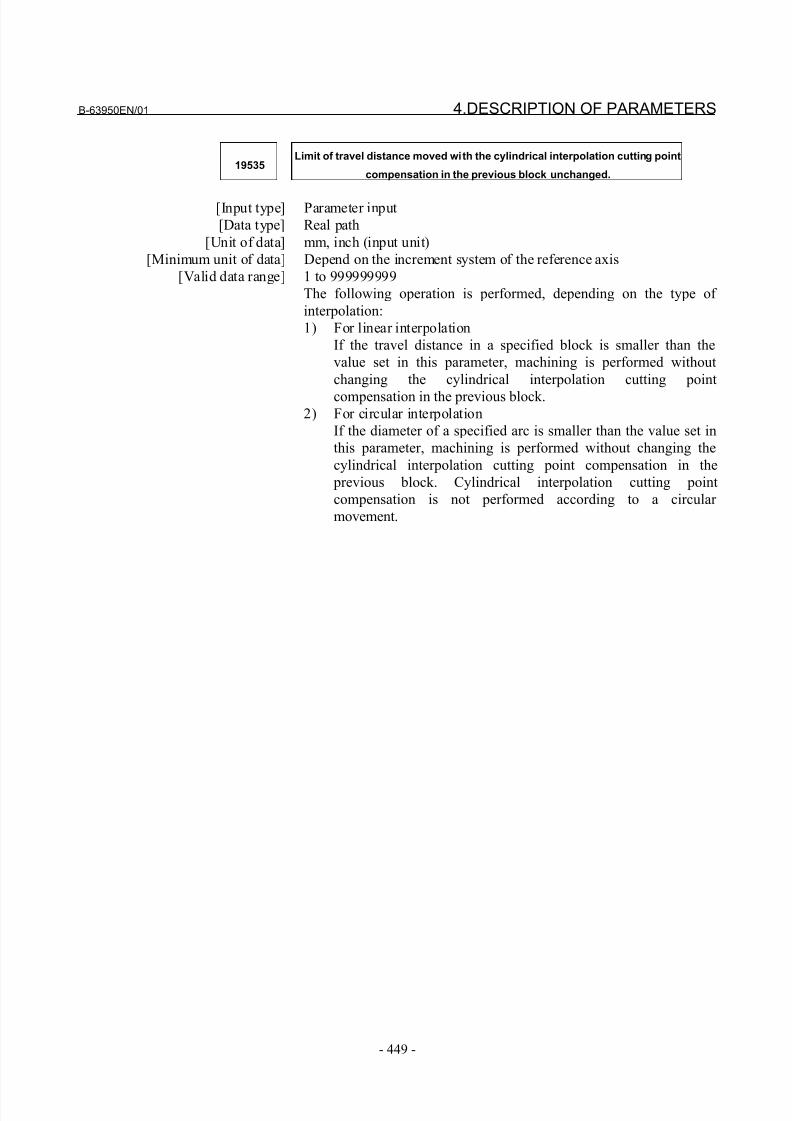
8/21/2019 30i Parameter Manual
http://slidepdf.com/reader/full/30i-parameter-manual 461/493
B-63950EN/01 4.DESCRIPTION OF PARAMETERS
- 449 -
19535Limit of travel distance moved with the cylindrical interpolation cutting point
compensation in the previous block unchanged.
[Input type] Parameter input
[Data type] Real path
[Unit of data] mm, inch (input unit)
[Minimum unit of data] Depend on the increment system of the reference axis
[Valid data range] 1 to 999999999
The following operation is performed, depending on the type of
interpolation:
1) For linear interpolation
If the travel distance in a specified block is smaller than the
value set in this parameter, machining is performed without
changing the cylindrical interpolation cutting point
compensation in the previous block.2) For circular interpolation
If the diameter of a specified arc is smaller than the value set in
this parameter, machining is performed without changing the
cylindrical interpolation cutting point compensation in the
previous block. Cylindrical interpolation cutting point
compensation is not performed according to a circular
movement.
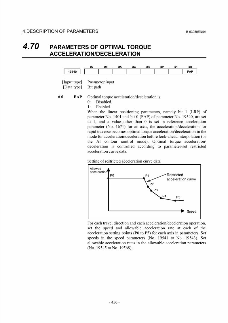
8/21/2019 30i Parameter Manual
http://slidepdf.com/reader/full/30i-parameter-manual 462/493
4.DESCRIPTION OF PARAMETERS B-63950EN/01
- 450 -
4.70 PARAMETERS OF OPTIMAL TORQUE
ACCELERATION/DECELERATION
#7 #6 #5 #4 #3 #2 #1 #0
19540 FAP
[Input type] Parameter input
[Data type] Bit path
# 0 FAP Optimal torque acceleration/deceleration is:
0: Disabled.
1: Enabled.
When the linear positioning parameters, namely bit 1 (LRP) of parameter No. 1401 and bit 0 (FAP) of parameter No. 19540, are set
to 1, and a value other than 0 is set in reference acceleration
parameter (No. 1671) for an axis, the acceleration/deceleration for
rapid traverse becomes optimal torque acceleration/deceleration in the
mode for acceleration/deceleration before look-ahead interpolation (or
the AI contour control mode). Optimal torque acceleration/
deceleration is controlled according to parameter-set restricted
acceleration curve data.
Setting of restricted acceleration curve data
Allowedacceleration
Speed
P0 P1
P2
P3
P4 P5
Restricted
acceleration curve
For each travel direction and each acceleration/deceleration operation,
set the speed and allowable acceleration rate at each of the
acceleration setting points (P0 to P5) for each axis in parameters. Set
speeds in the speed parameters (No. 19541 to No. 19543). Set
allowable acceleration rates in the allowable acceleration parameters
(No. 19545 to No. 19568).
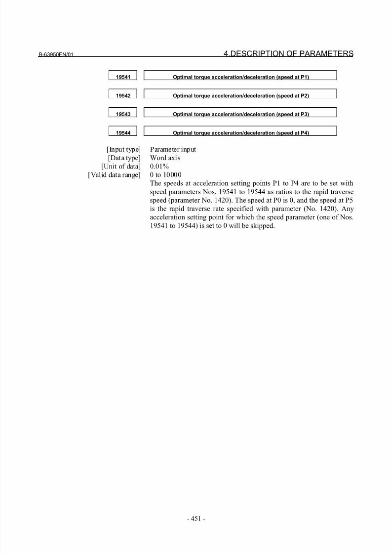
8/21/2019 30i Parameter Manual
http://slidepdf.com/reader/full/30i-parameter-manual 463/493
B-63950EN/01 4.DESCRIPTION OF PARAMETERS
- 451 -
19541 Optimal torque acceleration/deceleration (speed at P1)
19542 Optimal torque acceleration/deceleration (speed at P2)
19543 Optimal torque acceleration/deceleration (speed at P3)
19544 Optimal torque acceleration/deceleration (speed at P4)
[Input type] Parameter input
[Data type] Word axis
[Unit of data] 0.01%
[Valid data range] 0 to 10000
The speeds at acceleration setting points P1 to P4 are to be set with
speed parameters Nos. 19541 to 19544 as ratios to the rapid traversespeed (parameter No. 1420). The speed at P0 is 0, and the speed at P5
is the rapid traverse rate specified with parameter (No. 1420). Any
acceleration setting point for which the speed parameter (one of Nos.
19541 to 19544) is set to 0 will be skipped.
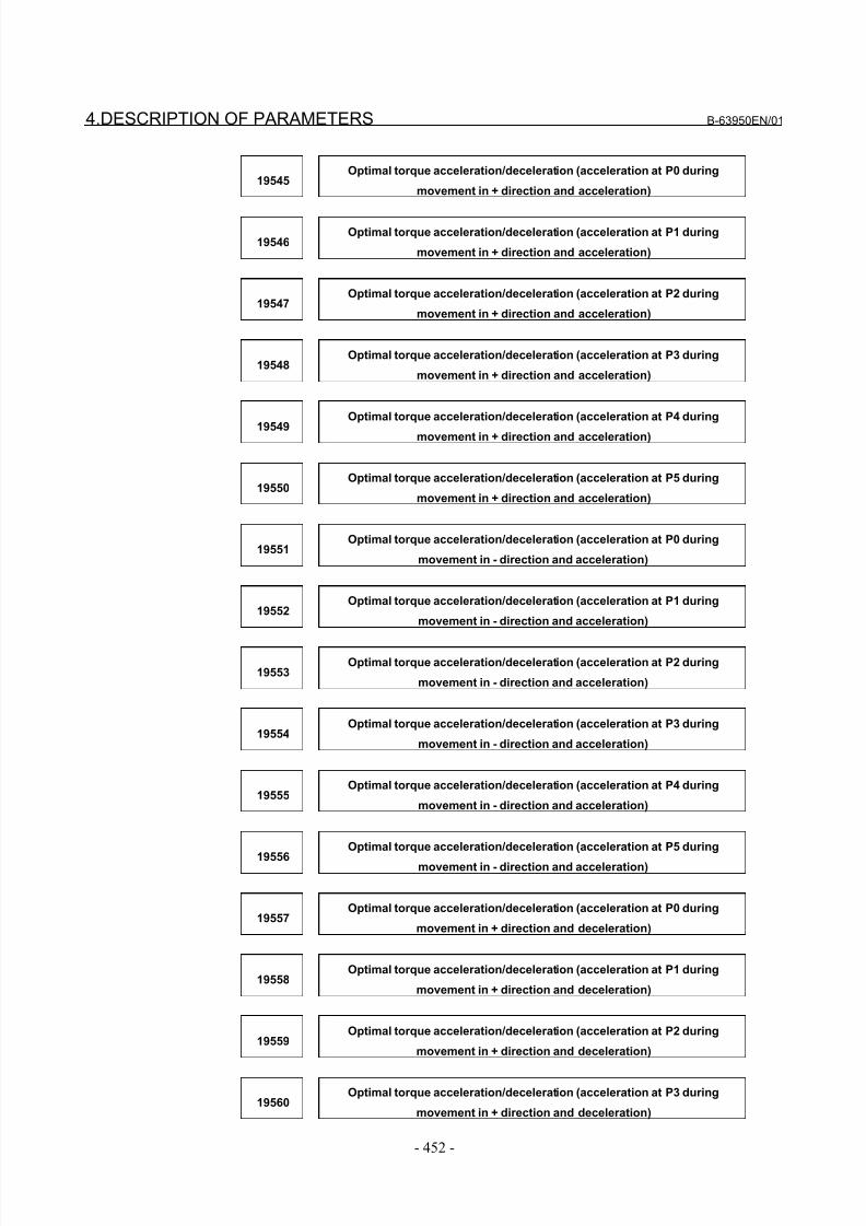
8/21/2019 30i Parameter Manual
http://slidepdf.com/reader/full/30i-parameter-manual 464/493
4.DESCRIPTION OF PARAMETERS B-63950EN/01
- 452 -
19545Optimal torque acceleration/deceleration (acceleration at P0 during
movement in + direction and acceleration)
19546Optimal torque acceleration/deceleration (acceleration at P1 during
movement in + direction and acceleration)
19547Optimal torque acceleration/deceleration (acceleration at P2 during
movement in + direction and acceleration)
19548Optimal torque acceleration/deceleration (acceleration at P3 during
movement in + direction and acceleration)
19549
Optimal torque acceleration/deceleration (acceleration at P4 during
movement in + direction and acceleration)
19550Optimal torque acceleration/deceleration (acceleration at P5 during
movement in + direction and acceleration)
19551Optimal torque acceleration/deceleration (acceleration at P0 during
movement in - direction and acceleration)
19552Optimal torque acceleration/deceleration (acceleration at P1 during
movement in - direction and acceleration)
19553Optimal torque acceleration/deceleration (acceleration at P2 during
movement in - direction and acceleration)
19554Optimal torque acceleration/deceleration (acceleration at P3 during
movement in - direction and acceleration)
19555Optimal torque acceleration/deceleration (acceleration at P4 during
movement in - direction and acceleration)
19556
Optimal torque acceleration/deceleration (acceleration at P5 during
movement in - direction and acceleration)
19557Optimal torque acceleration/deceleration (acceleration at P0 during
movement in + direction and deceleration)
19558Optimal torque acceleration/deceleration (acceleration at P1 during
movement in + direction and deceleration)
19559Optimal torque acceleration/deceleration (acceleration at P2 during
movement in + direction and deceleration)
19560Optimal torque acceleration/deceleration (acceleration at P3 during
movement in + direction and deceleration)
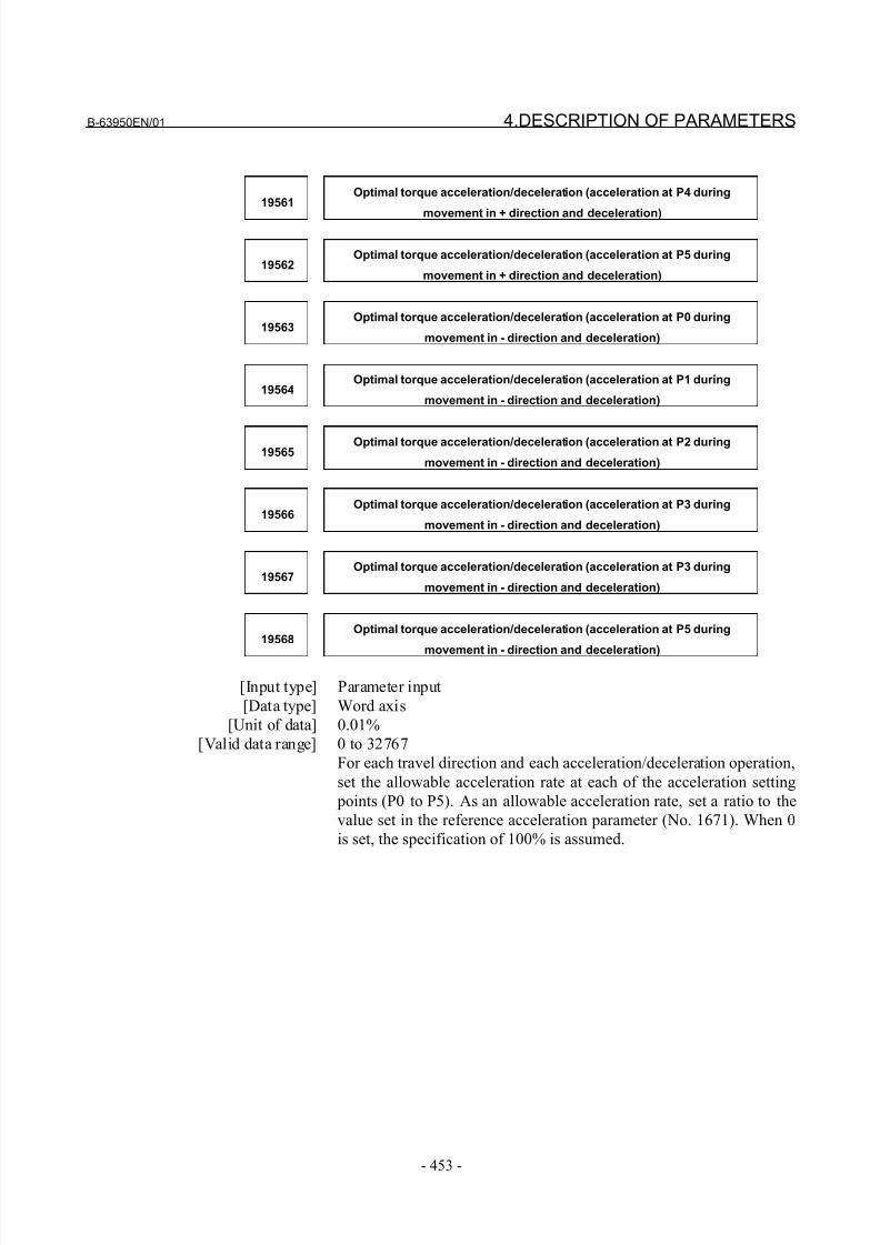
8/21/2019 30i Parameter Manual
http://slidepdf.com/reader/full/30i-parameter-manual 465/493
B-63950EN/01 4.DESCRIPTION OF PARAMETERS
- 453 -
19561Optimal torque acceleration/deceleration (acceleration at P4 during
movement in + direction and deceleration)
19562Optimal torque acceleration/deceleration (acceleration at P5 during
movement in + direction and deceleration)
19563Optimal torque acceleration/deceleration (acceleration at P0 during
movement in - direction and deceleration)
19564Optimal torque acceleration/deceleration (acceleration at P1 during
movement in - direction and deceleration)
19565Optimal torque acceleration/deceleration (acceleration at P2 during
movement in - direction and deceleration)
19566Optimal torque acceleration/deceleration (acceleration at P3 during
movement in - direction and deceleration)
19567Optimal torque acceleration/deceleration (acceleration at P3 during
movement in - direction and deceleration)
19568Optimal torque acceleration/deceleration (acceleration at P5 during
movement in - direction and deceleration)
[Input type] Parameter input
[Data type] Word axis
[Unit of data] 0.01%
[Valid data range] 0 to 32767
For each travel direction and each acceleration/deceleration operation,
set the allowable acceleration rate at each of the acceleration setting
points (P0 to P5). As an allowable acceleration rate, set a ratio to the
value set in the reference acceleration parameter (No. 1671). When 0
is set, the specification of 100% is assumed.
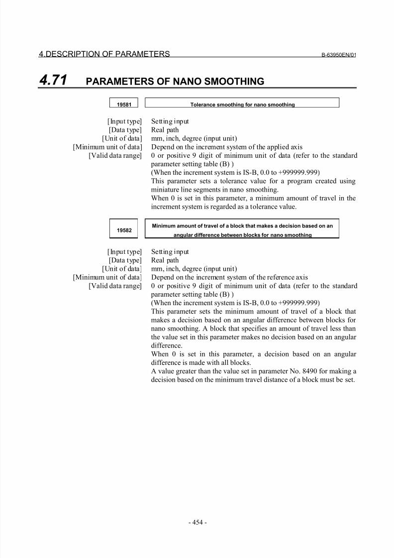
8/21/2019 30i Parameter Manual
http://slidepdf.com/reader/full/30i-parameter-manual 466/493
4.DESCRIPTION OF PARAMETERS B-63950EN/01
- 454 -
4.71 PARAMETERS OF NANO SMOOTHING
19581 Tolerance smoothing for nano smoothing
[Input type] Setting input
[Data type] Real path
[Unit of data] mm, inch, degree (input unit)
[Minimum unit of data] Depend on the increment system of the applied axis
[Valid data range] 0 or positive 9 digit of minimum unit of data (refer to the standard
parameter setting table (B) )
(When the increment system is IS-B, 0.0 to +999999.999)
This parameter sets a tolerance value for a program created using
miniature line segments in nano smoothing.
When 0 is set in this parameter, a minimum amount of travel in theincrement system is regarded as a tolerance value.
19582Minimum amount of travel of a block that makes a decision based on an
angular difference between blocks for nano smoothing
[Input type] Setting input
[Data type] Real path
[Unit of data] mm, inch, degree (input unit)
[Minimum unit of data] Depend on the increment system of the reference axis
[Valid data range] 0 or positive 9 digit of minimum unit of data (refer to the standard
parameter setting table (B) )(When the increment system is IS-B, 0.0 to +999999.999)
This parameter sets the minimum amount of travel of a block that
makes a decision based on an angular difference between blocks for
nano smoothing. A block that specifies an amount of travel less than
the value set in this parameter makes no decision based on an angular
difference.
When 0 is set in this parameter, a decision based on an angular
difference is made with all blocks.
A value greater than the value set in parameter No. 8490 for making a
decision based on the minimum travel distance of a block must be set.

8/21/2019 30i Parameter Manual
http://slidepdf.com/reader/full/30i-parameter-manual 467/493
B-63950EN/01 4.DESCRIPTION OF PARAMETERS
- 455 -
4.72 PARAMETERS OF TOOL COMPENSATION (2 OF 2)
#7 #6 #5 #4 #3 #2 #1 #0
NAG NAA CAV CCC19607
NAG NAA CAV WCD CCC
[Input type] Parameter input
[Data type] Bit path
# 2 CCC In the cutter compensation/tool nose radius compensation mode, the
outer corner connection method is based on:
0: Linear connection type.
1: Circular connection type.
# 5 CAV When an interference check finds that interference (overcutting)
occurred:
0: Machining stops with the alarm (PS0041).
(Interference check alarm function)
1: Machining is continued by changing the tool path to prevent
interference (overcutting) from occurring. (Interference check
avoidance function)
For the interference check method, see the descriptions of bit 1 (CNC)
of parameter No. 5008 and bit 3 (CNV) of parameter No. 5008.
# 6 NAA When the interference check avoidance function considers that anavoidance operation is dangerous or that a further interference to the
interference avoidance vector occurs:
0: An alarm is issued.
When an avoidance operation is considered to be dangerous, the
alarm (PS5447) is issued.
When a further interference to the interference avoidance vector
is considered to occur, the alarm (PS5448) is issued.
1: No alarm is issued, and the avoidance operation is continued.
NOTE
Usually, set this parameter to 0.
# 7 NAG If the gap vector length is 0 when the interference check avoidance
function for cutter compensation/tool nose radius compensation is
used:
0: Avoidance operation is performed.
1: Avoidance operation is not performed.
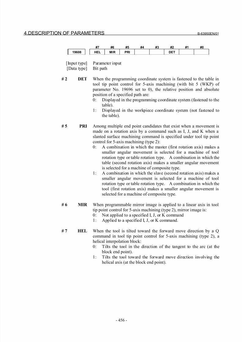
8/21/2019 30i Parameter Manual
http://slidepdf.com/reader/full/30i-parameter-manual 468/493
4.DESCRIPTION OF PARAMETERS B-63950EN/01
- 456 -
#7 #6 #5 #4 #3 #2 #1 #0
19608 HEL MIR PRI DET
[Input type] Parameter input
[Data type] Bit path
# 2 DET When the programming coordinate system is fastened to the table in
tool tip point control for 5-axis machining (with bit 5 (WKP) of
parameter No. 19696 set to 0), the relative position and absolute
position of a specified path are:
0: Displayed in the programming coordinate system (fastened to the
table).
1: Displayed in the workpiece coordinate system (not fastened to
the table).
# 5 PRI Among multiple end point candidates that exist when a movement is
made on a rotation axis by a command such as I, J, and K when a
slanted surface machining command is specified under tool tip point
control for 5-axis machining (type 2):
0: A combination in which the master (first rotation axis) makes a
smaller angular movement is selected for a machine of tool
rotation type or table rotation type. A combination in which the
table (second rotation axis) makes a smaller angular movement
is selected for a machine of composite type.
1: A combination in which the slave (second rotation axis) makes a
smaller angular movement is selected for a machine of toolrotation type or table rotation type. A combination in which the
tool (first rotation axis) makes a smaller angular movement is
selected for a machine of composite type.
# 6 MIR When programmable mirror image is applied to a linear axis in tool
tip point control for 5-axis machining (type 2), mirror image is:
0: Not applied to a specified I, J, or K command
1: Applied to a specified I, J, or K command.
# 7 HEL When the tool is tilted toward the forward move direction by a Q
command in tool tip point control for 5-axis machining (type 2), a
helical interpolation block:0: Tilts the tool in the direction of the tangent to the arc (at the
block end point).
1: Tilts the tool toward the forward move direction involving the
helical axis (at the block end point).
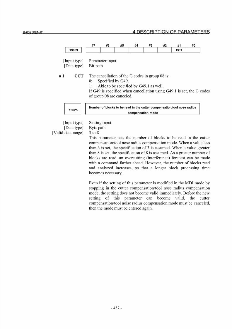
8/21/2019 30i Parameter Manual
http://slidepdf.com/reader/full/30i-parameter-manual 469/493
B-63950EN/01 4.DESCRIPTION OF PARAMETERS
- 457 -
#7 #6 #5 #4 #3 #2 #1 #0
19609 CCT
[Input type] Parameter input
[Data type] Bit path
# 1 CCT The cancellation of the G codes in group 08 is:
0: Specified by G49.
1: Able to be specified by G49.1 as well.
If G49 is specified when cancellation using G49.1 is set, the G codes
of group 08 are canceled.
19625Number of blocks to be read in the cutter compensation/tool nose radius
compensation mode
[Input type] Setting input
[Data type] Byte path
[Valid data range] 3 to 8
This parameter sets the number of blocks to be read in the cutter
compensation/tool nose radius compensation mode. When a value less
than 3 is set, the specification of 3 is assumed. When a value greater
than 8 is set, the specification of 8 is assumed. As a greater number of
blocks are read, an overcutting (interference) forecast can be made
with a command farther ahead. However, the number of blocks read
and analyzed increases, so that a longer block processing time
becomes necessary.
Even if the setting of this parameter is modified in the MDI mode by
stopping in the cutter compensation/tool nose radius compensation
mode, the setting does not become valid immediately. Before the new
setting of this parameter can become valid, the cutter
compensation/tool noise radius compensation mode must be canceled,
then the mode must be entered again.
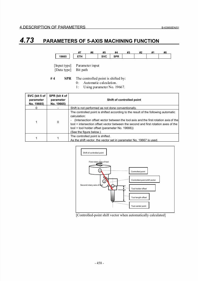
8/21/2019 30i Parameter Manual
http://slidepdf.com/reader/full/30i-parameter-manual 470/493
4.DESCRIPTION OF PARAMETERS B-63950EN/01
- 458 -
4.73 PARAMETERS OF 5-AXIS MACHINING FUNCTION
#7 #6 #5 #4 #3 #2 #1 #0
19665 ETH SVC SPR
[Input type] Parameter input
[Data type] Bit path
# 4 SPR The controlled point is shifted by:
0: Automatic calculation.
1: Using parameter No. 19667.
SVC (bit 5 of
parameter
No. 19665)
SPR (bit 4 of
parameter
No. 19665)
Shift of controlled point
0 - Shift is not performed as not done conventionally.
1 0
The controlled point is shifted according to the result of the following automatic
calculation:
- (Intersection offset vector between the tool axis and the first rotation axis of the
tool + intersection offset vector between the second and first rotation axes of the
tool + tool holder offset (parameter No. 19666))
(See the figure below.)
1 1The controlled point is shifted.
As the shift vector, the vector set in parameter No. 19667 is used.
Shift of controlled point
Tool length offset
Tool holder offset
Controlled-point shift vector
D
E
Tool center point
Controlled point
Second rotary axis of tool
F
First rotary axis of tool
[Controlled-point shift vector when automatically calculated]
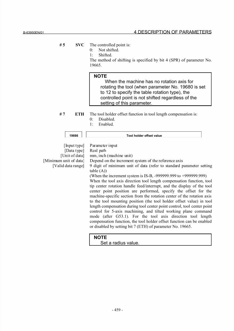
8/21/2019 30i Parameter Manual
http://slidepdf.com/reader/full/30i-parameter-manual 471/493
B-63950EN/01 4.DESCRIPTION OF PARAMETERS
- 459 -
# 5 SVC The controlled point is:
0: Not shifted.
1: Shifted.
The method of shifting is specified by bit 4 (SPR) of parameter No.
19665.
NOTEWhen the machine has no rotation axis for
rotating the tool (when parameter No. 19680 is setto 12 to specify the table rotation type), thecontrolled point is not shifted regardless of thesetting of this parameter.
# 7 ETHThe tool holder offset function in tool length compensation is:0: Disabled.
1: Enabled.
19666 Tool holder offset value
[Input type] Parameter input
[Data type] Real path
[Unit of data] mm, inch (machine unit)
[Minimum unit of data] Depend on the increment system of the reference axis
[Valid data range] 9 digit of minimum unit of data (refer to standard parameter setting
table (A))
(When the increment system is IS-B, -999999.999 to +999999.999)
When the tool axis direction tool length compensation function, tool
tip center rotation handle feed/interrupt, and the display of the tool
center point position are performed, specify the offset for the
machine-specific section from the rotation center of the rotation axis
to the tool mounting position (the tool holder offset value) in tool
length compensation during tool center point control, tool center point
control for 5-axis machining, and tilted working plane command
mode (after G53.1). For the tool axis direction tool length
compensation function, the tool holder offset function can be enabled
or disabled by setting bit 7 (ETH) of parameter No. 19665.
NOTESet a radius value.
8/21/2019 30i Parameter Manual
http://slidepdf.com/reader/full/30i-parameter-manual 472/493
4.DESCRIPTION OF PARAMETERS B-63950EN/01
- 460 -
19667 Controlled-point shift vector
[Input type] Parameter input[Data type] Real axis
[Unit of data] mm, inch (machine unit)
[Minimum unit of data] Depend on the increment system of the applied axis
[Valid data range] 9 digit of minimum unit of data (refer to standard parameter setting
table (A))
(When the increment system is IS-B, -999999.999 to +999999.999)
Set the shift vector for the controlled point. This value becomes valid
when bit 5 (SVC) of parameter No. 19665 is set to 1, and bit 4 (SPR)
of parameter No. 19665 is set to 1.
NOTESet a radius value.
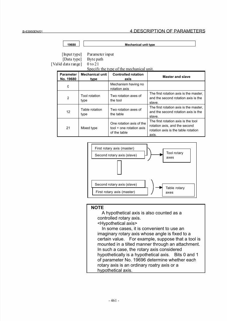
8/21/2019 30i Parameter Manual
http://slidepdf.com/reader/full/30i-parameter-manual 473/493
B-63950EN/01 4.DESCRIPTION OF PARAMETERS
- 461 -
19680 Mechanical unit type
[Input type] Parameter input[Data type] Byte path
[Valid data range] 0 to 21
Specify the type of the mechanical unit.
Parameter
No. 19680
Mechanical unit
type
Controlled rotation
axisMaster and slave
0Mechanism having no
rotation axis
2Tool rotation
type
Two rotation axes of
the tool
The first rotation axis is the master,
and the second rotation axis is the
slave.
12
Table rotation
type
Two rotation axes of
the table
The first rotation axis is the master,
and the second rotation axis is theslave.
21 Mixed type
One rotation axis of the
tool + one rotation axis
of the table
The first rotation axis is the tool
rotation axis, and the second
rotation axis is the table rotation
axis.
First rotary axis (master)
Second rotary axis (slave)
First rotary axis (master)
Second rotary axis (slave)Tool rotary
axes
Table rotary
axes
NOTE A hypothetical axis is also counted as a
controlled rotary axis.
<Hypothetical axis>In some cases, it is convenient to use animaginary rotary axis whose angle is fixed to acertain value. For example, suppose that a tool ismounted in a tilted manner through an attachment.In such a case, the rotary axis consideredhypothetically is a hypothetical axis. Bits 0 and 1of parameter No. 19696 determine whether eachrotary axis is an ordinary roatry axis or ahypothetical axis.
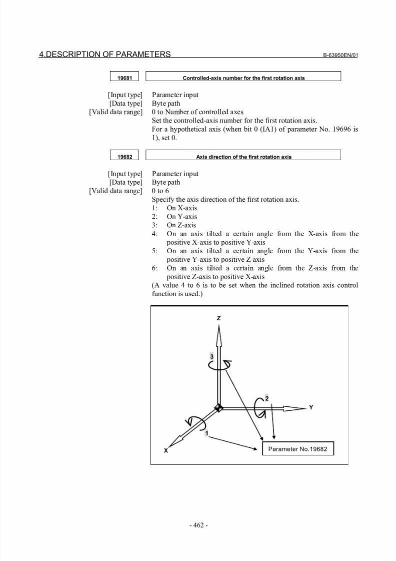
8/21/2019 30i Parameter Manual
http://slidepdf.com/reader/full/30i-parameter-manual 474/493
4.DESCRIPTION OF PARAMETERS B-63950EN/01
- 462 -
19681 Controlled-axis number for the first rotation axis
[Input type] Parameter input[Data type] Byte path
[Valid data range] 0 to Number of controlled axes
Set the controlled-axis number for the first rotation axis.
For a hypothetical axis (when bit 0 (IA1) of parameter No. 19696 is
1), set 0.
19682 Axis direction of the first rotation axis
[Input type] Parameter input
[Data type] Byte path
[Valid data range] 0 to 6
Specify the axis direction of the first rotation axis.
1: On X-axis
2: On Y-axis
3: On Z-axis
4: On an axis tilted a certain angle from the X-axis from the
positive X-axis to positive Y-axis
5: On an axis tilted a certain angle from the Y-axis from the
positive Y-axis to positive Z-axis
6: On an axis tilted a certain angle from the Z-axis from the
positive Z-axis to positive X-axis
(A value 4 to 6 is to be set when the inclined rotation axis control
function is used.)
Y
Z
X
2
3
1
Parameter No.19682
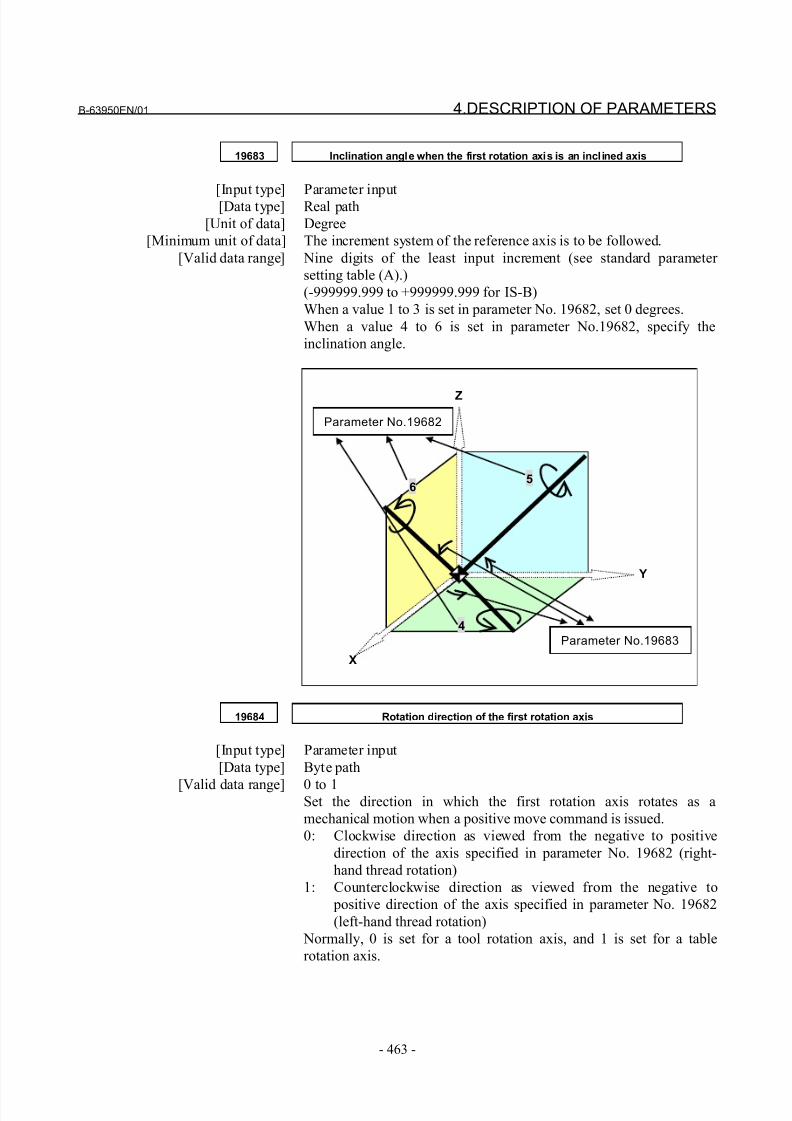
8/21/2019 30i Parameter Manual
http://slidepdf.com/reader/full/30i-parameter-manual 475/493
B-63950EN/01 4.DESCRIPTION OF PARAMETERS
- 463 -
19683 Inclination angle when the first rotation axis is an inclined axis
[Input type] Parameter input[Data type] Real path
[Unit of data] Degree
[Minimum unit of data] The increment system of the reference axis is to be followed.
[Valid data range] Nine digits of the least input increment (see standard parameter
setting table (A).)
(-999999.999 to +999999.999 for IS-B)
When a value 1 to 3 is set in parameter No. 19682, set 0 degrees.
When a value 4 to 6 is set in parameter No.19682, specify the
inclination angle.
Parameter No.19682
Y
Z
X
5
4
6
Parameter No.19683
19684 Rotation direction of the first rotation axis
[Input type] Parameter input
[Data type] Byte path
[Valid data range] 0 to 1Set the direction in which the first rotation axis rotates as a
mechanical motion when a positive move command is issued.
0: Clockwise direction as viewed from the negative to positive
direction of the axis specified in parameter No. 19682 (right-
hand thread rotation)
1: Counterclockwise direction as viewed from the negative to
positive direction of the axis specified in parameter No. 19682
(left-hand thread rotation)
Normally, 0 is set for a tool rotation axis, and 1 is set for a table
rotation axis.
8/21/2019 30i Parameter Manual
http://slidepdf.com/reader/full/30i-parameter-manual 476/493
4.DESCRIPTION OF PARAMETERS B-63950EN/01
- 464 -
19685 Rotation angle when the first rotation axis is a hypothetical axis
[Input type] Parameter input[Data type] Real path
[Unit of data] Degree
[Minimum unit of data] Depend on the increment system of the reference axis
[Valid data range] 9 digit of minimum unit of data (refer to standard parameter setting
table (A))
(When the increment system is IS-B, -999999.999 to +999999.999)
When the first rotation axis is a hypothetical axis (bit 0 (IA1) of
parameter No. 19696 is 1), set the rotation angle.
19686 Controlled-axis number for the second rotation axis
[Input type] Parameter input
[Data type] Byte path
[Valid data range] 0 to Number of controlled axes
Set the controlled-axis number for the second rotation axis.
For a hypothetical axis (bit 1 (IA2) of parameter No. 19696 is 1), set
0.
19687 Axis direction of the second rotation axis
[Input type] Parameter input
[Data type] Byte path
[Valid data range] 0 to 6Specify the axis direction of the second rotation axis.
1: On X-axis
2: On Y-axis
3: On Z-axis
4: On an axis tilted a certain angle from the X-axis from the
positive X-axis to positive Y-axis
5: On an axis tilted a certain angle from the Y-axis from the
positive Y-axis to positive Z-axis
6: On an axis tilted a certain angle from the Z-axis from the
positive Z-axis to positive X-axis
(A value 4 to 6 is to be set when the inclined rotation axis controlfunction is used.)
When the second rotation axis is the slave axis, the direction when the
master axis is at 0 degrees must be set.
8/21/2019 30i Parameter Manual
http://slidepdf.com/reader/full/30i-parameter-manual 477/493
B-63950EN/01 4.DESCRIPTION OF PARAMETERS
- 465 -
19688 Inclination angle when the second rotation axis is inclined
[Input type] Parameter input[Data type] Real path
[Unit of data] Degree
[Minimum unit of data] Depend on the increment system of the reference axis
[Valid data range] 9 digit of minimum unit of data (refer to standard parameter setting
(When the increment system is IS-B, -999999.999 to +999999.999)
If parameter No. 19687 is set to a value 1 to 3, set 0 degrees.
If parameter No. 19687 is set to a value 4 to 6, set the inclination
angle.
19689 Rotation direction of the second rotation axis
[Input type] Parameter input
[Data type] Byte path
[Valid data range] 0 to 1
Set the direction in which the second rotation axis rotates as a
mechanical motion when a positive move command is issued.
0: Clockwise direction as viewed from the negative to positive
direction of the axis specified in parameter No. 19687 (right-
hand thread rotation)
1: Counterclockwise direction as viewed from the negative to
positive direction of the axis specified in parameter No. 19687
(left-hand thread rotation)
Normally, 0 is set for a tool rotation axis, and 1 is set for a tablerotation axis.
19690 Rotation angle when the second rotation axis is a hypothetical axis
[Input type] Parameter input
[Data type] Real path
[Unit of data] Degree
[Minimum unit of data] Depend on the increment system of the reference axis
[Valid data range] 9 digit of minimum unit of data (refer to standard parameter setting
table (A))
(When the increment system is IS-B, -999999.999 to +999999.999)When the second rotation axis is a hypothetical axis (bit 1 (IA2) of
parameter No. 19696 is 1), set the rotation angle.
8/21/2019 30i Parameter Manual
http://slidepdf.com/reader/full/30i-parameter-manual 478/493
4.DESCRIPTION OF PARAMETERS B-63950EN/01
- 466 -
#7 #6 #5 #4 #3 #2 #1 #0
19696 SUP RFC WKP IA2 IA1
[Input type] Parameter input
[Data type] Bit path
# 0 IA1
0: The first rotation axis is an ordinary rotation axis.
1: The first rotation axis is a hypothetical axis.
If IA1 is 1, set 0 as the controlled-axis number for the first rotation
axis (parameter No. 19681).
Also, set parameter Nos. 19682 to 19685 on the assumption that there
is a rotation axis.
# 1 IA2
0: The second rotation axis is an ordinary rotation axis.
1: The second rotation axis is a hypothetical axis.
If IA2 is 1, set 0 as the controlled-axis number for the second rotation
axis (parameter No. 19686).
Also, set parameter Nos. 19687 to 19690 on the assumption that there
is a rotation axis.
# 5 WKP The programming coordinate system used for tool center point control
is:
0: A coordinate system fixed on the rotary table.
1: The workpiece coordinate system.
# 6 RFC In tool center point control for 5-axis machining, when a command
that does not move the tool center point with respect to the workpiece
is issued, the feedrate of the rotation axis is:
0: The maximum cutting feedrate (parameter No. 1422).
1: A specified feedrate.
# 7 SUP In tool center point control and tool center point control for 5-axis
machining, when a movement at a specified feedrate causes the
deviation of the path to exceed the permissible level:
0: The feedrate is not decreased.
1: The feedrate is decreased so that the deviation of the path iswithin the permissible level.
The permissible level is specified in parameter No. 19745.
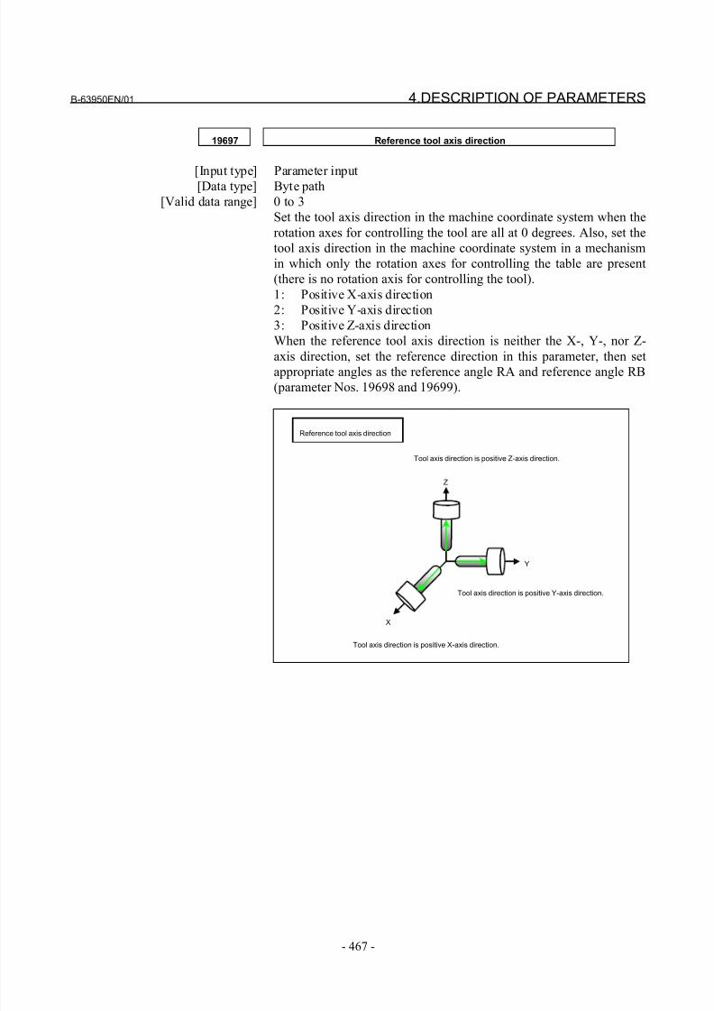
8/21/2019 30i Parameter Manual
http://slidepdf.com/reader/full/30i-parameter-manual 479/493
B-63950EN/01 4.DESCRIPTION OF PARAMETERS
- 467 -
19697 Reference tool axis direction
[Input type] Parameter input[Data type] Byte path
[Valid data range] 0 to 3
Set the tool axis direction in the machine coordinate system when the
rotation axes for controlling the tool are all at 0 degrees. Also, set the
tool axis direction in the machine coordinate system in a mechanism
in which only the rotation axes for controlling the table are present
(there is no rotation axis for controlling the tool).
1: Positive X-axis direction
2: Positive Y-axis direction
3: Positive Z-axis direction
When the reference tool axis direction is neither the X-, Y-, nor Z-
axis direction, set the reference direction in this parameter, then setappropriate angles as the reference angle RA and reference angle RB
(parameter Nos. 19698 and 19699).
Reference tool axis direction
X
Y
Z
Tool axis direction is positive X-axis direction.
Tool axis direction is positive Y-axis direction.
Tool axis direction is positive Z-axis direction.
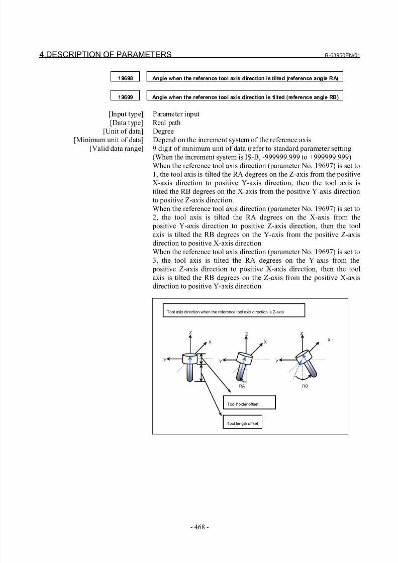
8/21/2019 30i Parameter Manual
http://slidepdf.com/reader/full/30i-parameter-manual 480/493
4.DESCRIPTION OF PARAMETERS B-63950EN/01
- 468 -
19698 Angle when the reference tool axis direction is tilted (reference angle RA)
19699 Angle when the reference tool axis direction is tilted (reference angle RB)
[Input type] Parameter input
[Data type] Real path
[Unit of data] Degree
[Minimum unit of data] Depend on the increment system of the reference axis
[Valid data range] 9 digit of minimum unit of data (refer to standard parameter setting
(When the increment system is IS-B, -999999.999 to +999999.999)
When the reference tool axis direction (parameter No. 19697) is set to
1, the tool axis is tilted the RA degrees on the Z-axis from the positive
X-axis direction to positive Y-axis direction, then the tool axis is
tilted the RB degrees on the X-axis from the positive Y-axis direction
to positive Z-axis direction.
When the reference tool axis direction (parameter No. 19697) is set to
2, the tool axis is tilted the RA degrees on the X-axis from the
positive Y-axis direction to positive Z-axis direction, then the tool
axis is tilted the RB degrees on the Y-axis from the positive Z-axis
direction to positive X-axis direction.
When the reference tool axis direction (parameter No. 19697) is set to
3, the tool axis is tilted the RA degrees on the Y-axis from the
positive Z-axis direction to positive X-axis direction, then the tool
axis is tilted the RB degrees on the Z-axis from the positive X-axis
direction to positive Y-axis direction.
Tool axis direction when the reference tool axis direction is Z-axis
RA
X
Y
Z
X
Y
Z
RB
X
Z
Tool holder offset
Tool length offset
Y
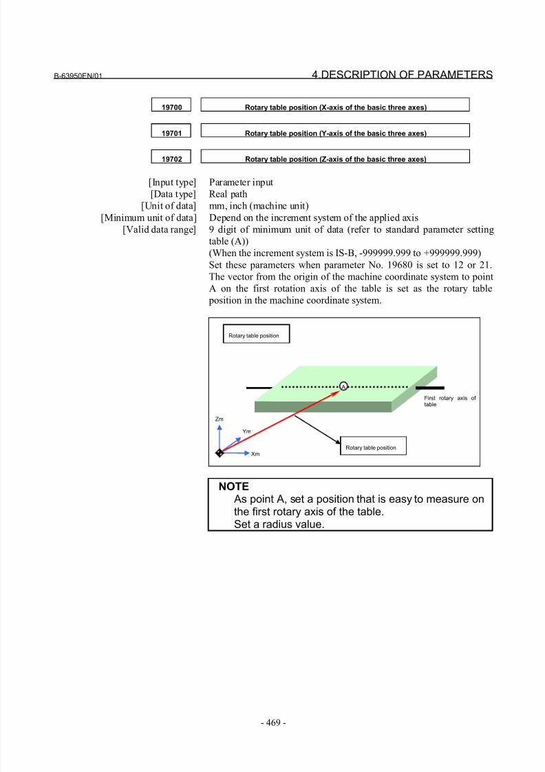
8/21/2019 30i Parameter Manual
http://slidepdf.com/reader/full/30i-parameter-manual 481/493
B-63950EN/01 4.DESCRIPTION OF PARAMETERS
- 469 -
19700 Rotary table position (X-axis of the basic three axes)
19701 Rotary table position (Y-axis of the basic three axes)
19702 Rotary table position (Z-axis of the basic three axes)
[Input type] Parameter input
[Data type] Real path
[Unit of data] mm, inch (machine unit)
[Minimum unit of data] Depend on the increment system of the applied axis
[Valid data range] 9 digit of minimum unit of data (refer to standard parameter setting
table (A))
(When the increment system is IS-B, -999999.999 to +999999.999)
Set these parameters when parameter No. 19680 is set to 12 or 21.
The vector from the origin of the machine coordinate system to point
A on the first rotation axis of the table is set as the rotary table
position in the machine coordinate system.
Rotary table position
Zm
Ym
Xm
First rotary axis of
table
Rotary table position
A
NOTE As point A, set a position that is easy to measure onthe first rotary axis of the table.Set a radius value.
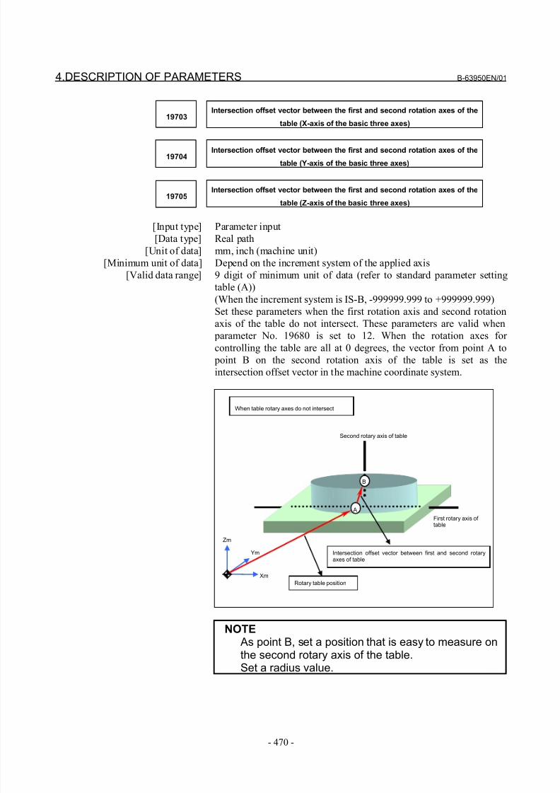
8/21/2019 30i Parameter Manual
http://slidepdf.com/reader/full/30i-parameter-manual 482/493
4.DESCRIPTION OF PARAMETERS B-63950EN/01
- 470 -
19703Intersection offset vector between the first and second rotation axes of the
table (X-axis of the basic three axes)
19704Intersection offset vector between the first and second rotation axes of the
table (Y-axis of the basic three axes)
19705Intersection offset vector between the first and second rotation axes of the
table (Z-axis of the basic three axes)
[Input type] Parameter input
[Data type] Real path
[Unit of data] mm, inch (machine unit)
[Minimum unit of data] Depend on the increment system of the applied axis
[Valid data range] 9 digit of minimum unit of data (refer to standard parameter settingtable (A))
(When the increment system is IS-B, -999999.999 to +999999.999)
Set these parameters when the first rotation axis and second rotation
axis of the table do not intersect. These parameters are valid when
parameter No. 19680 is set to 12. When the rotation axes for
controlling the table are all at 0 degrees, the vector from point A to
point B on the second rotation axis of the table is set as the
intersection offset vector in the machine coordinate system.
When table rotary axes do not intersect
Zm
Ym
Xm
Second rotary axis of table
First rotary axis of table
Rotary table position
Intersection offset vector between first and second rotaryaxes of table
B
A
NOTE As point B, set a position that is easy to measure onthe second rotary axis of the table.Set a radius value.
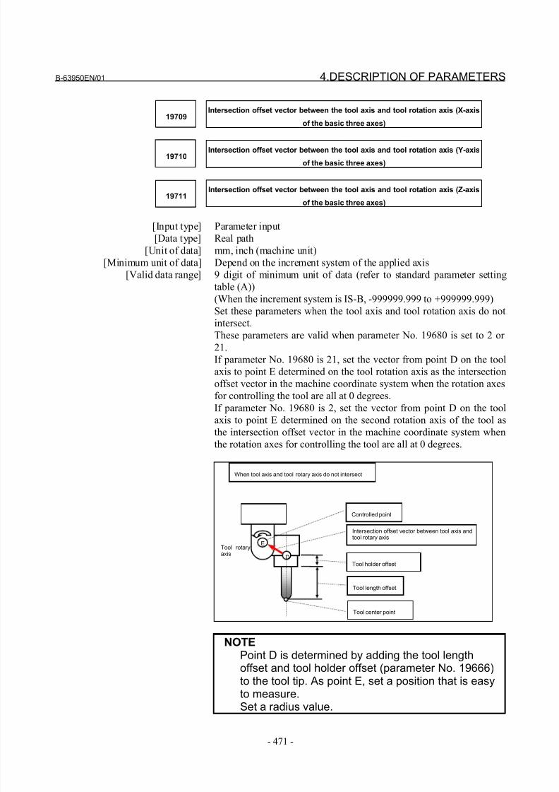
8/21/2019 30i Parameter Manual
http://slidepdf.com/reader/full/30i-parameter-manual 483/493
B-63950EN/01 4.DESCRIPTION OF PARAMETERS
- 471 -
19709Intersection offset vector between the tool axis and tool rotation axis (X-axis
of the basic three axes)
19710Intersection offset vector between the tool axis and tool rotation axis (Y-axis
of the basic three axes)
19711Intersection offset vector between the tool axis and tool rotation axis (Z-axis
of the basic three axes)
[Input type] Parameter input
[Data type] Real path
[Unit of data] mm, inch (machine unit)
[Minimum unit of data] Depend on the increment system of the applied axis
[Valid data range] 9 digit of minimum unit of data (refer to standard parameter settingtable (A))
(When the increment system is IS-B, -999999.999 to +999999.999)
Set these parameters when the tool axis and tool rotation axis do not
intersect.
These parameters are valid when parameter No. 19680 is set to 2 or
21.
If parameter No. 19680 is 21, set the vector from point D on the tool
axis to point E determined on the tool rotation axis as the intersection
offset vector in the machine coordinate system when the rotation axes
for controlling the tool are all at 0 degrees.
If parameter No. 19680 is 2, set the vector from point D on the tool
axis to point E determined on the second rotation axis of the tool asthe intersection offset vector in the machine coordinate system when
the rotation axes for controlling the tool are all at 0 degrees.
When tool axis and tool rotary axis do not intersect
Tool length offset
Tool holder offset
Intersection offset vector between tool axis andtool rotary axis
D
E
Tool center point
Controlled point
Tool rotary
axis
NOTEPoint D is determined by adding the tool lengthoffset and tool holder offset (parameter No. 19666)to the tool tip. As point E, set a position that is easy
to measure.Set a radius value.
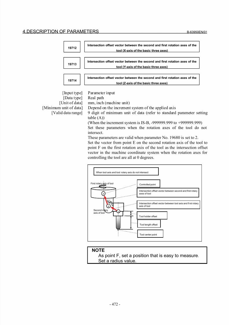
8/21/2019 30i Parameter Manual
http://slidepdf.com/reader/full/30i-parameter-manual 484/493
4.DESCRIPTION OF PARAMETERS B-63950EN/01
- 472 -
19712Intersection offset vector between the second and first rotation axes of the
tool (X-axis of the basic three axes)
19713Intersection offset vector between the second and first rotation axes of the
tool (Y-axis of the basic three axes)
19714Intersection offset vector between the second and first rotation axes of the
tool (Z-axis of the basic three axes)
[Input type] Parameter input
[Data type] Real path
[Unit of data] mm, inch (machine unit)
[Minimum unit of data] Depend on the increment system of the applied axis
[Valid data range] 9 digit of minimum unit of data (refer to standard parameter settingtable (A))
(When the increment system is IS-B, -999999.999 to +999999.999)
Set these parameters when the rotation axes of the tool do not
intersect.
These parameters are valid when parameter No. 19680 is set to 2.
Set the vector from point E on the second rotation axis of the tool to
point F on the first rotation axis of the tool as the intersection offset
vector in the machine coordinate system when the rotation axes for
controlling the tool are all at 0 degrees.
When tool axis and tool rotary axis do not intersect
Tool length offset
Tool holder offset
Intersection offset vector between tool axis and fi rst rotaryaxis of tool
D
E
Tool center point
Controlled point
Second rotaryaxis of tool
F
First rotary axis of tool
Intersection offset vector between second and first rotaryaxes of tool
NOTE As point F, set a position that is easy to measure.Set a radius value.
8/21/2019 30i Parameter Manual
http://slidepdf.com/reader/full/30i-parameter-manual 485/493
B-63950EN/01 4.DESCRIPTION OF PARAMETERS
- 473 -
19741 Upper limit of the movement range of the first rotation axis
[Input type] Parameter input[Data type] Real path
[Unit of data] Degree
[Minimum unit of data] Depend on the increment system of the reference axis
[Valid data range] 9 digit of minimum unit of data (refer to standard parameter setting
(When the increment system is IS-B, -999999.999 to +999999.999)
In tool center point control for 5-axis machining (type 2), set the
upper limit of the movement range of the first rotation axis. When the
movement range of the first rotation axis is not specified, this
parameter and parameter No. 19742 must both be set to 0.
19742 Lower limit of the movement range of the first rotation axis
[Input type] Parameter input
[Data type] Real path
[Unit of data] Degree
[Minimum unit of data] Depend on the increment system of the reference axis
[Valid data range] 9 digit of minimum unit of data (refer to standard parameter setting
(When the increment system is IS-B, -999999.999 to +999999.999)
In tool center point control for 5-axis machining (type 2), set the
lower limit of the movement range of the first rotation axis. When the
movement range of the first rotation axis is not specified, this
parameter and parameter No. 19741 must both be set to 0.
19743 Upper l imit of the movement range of the second rotation axis
[Input type] Parameter input
[Data type] Real path
[Unit of data] Degree
[Minimum unit of data] Depend on the increment system of the reference axis
[Valid data range] 9 digit of minimum unit of data (refer to standard parameter setting
(When the increment system is IS-B, -999999.999 to +999999.999)
In tool center point control for 5-axis machining (type 2), set the
upper limit of the movement range of the second rotation axis.
When the movement range of the second rotation axis is not specified,this parameter and parameter No. 19744 must both be set to 0.
8/21/2019 30i Parameter Manual
http://slidepdf.com/reader/full/30i-parameter-manual 486/493
4.DESCRIPTION OF PARAMETERS B-63950EN/01
- 474 -
19744 Lower limit of the movement range of the second rotation axis
[Input type] Parameter input[Data type] Real path
[Unit of data] Degree
[Minimum unit of data] Depend on the increment system of the reference axis
[Valid data range] 9 digit of minimum unit of data (refer to standard parameter setting
(When the increment system is IS-B, -999999.999 to +999999.999)
In tool center point control for 5-axis machining (type 2), set the
lower limit of the movement range of the second rotation axis. When
the movement range of the second rotation axis is not specified, this
parameter and parameter No. 19743 must both be set to 0.
19745 Permissible level of the deviation of the path
[Input type] Parameter input
[Data type] Real path
[Unit of data] mm, inch (input unit)
[Minimum unit of data] Depend on the increment system of the reference axis
[Valid data range] 9 digit of minimum unit of data (refer to standard parameter setting
(When the increment system is IS-B, -999999.999 to +999999.999)
In tool center point control for 5-axis machining, set the permissible
level of the deviation of the tool.
If a movement at a specified feedrate causes the deviation of the path
to exceed the level specified in this parameter, the feedrate is
decreased so that the path deviation can be eliminated.If 0 is set in this parameter, the least input increment is assumed to be
the permissible level of the deviation of the path.
This parameter becomes valid when bit 7 (SUP) of parameter No.
19696 is set to 1.

8/21/2019 30i Parameter Manual
http://slidepdf.com/reader/full/30i-parameter-manual 487/493
APPENDIX

8/21/2019 30i Parameter Manual
http://slidepdf.com/reader/full/30i-parameter-manual 488/493
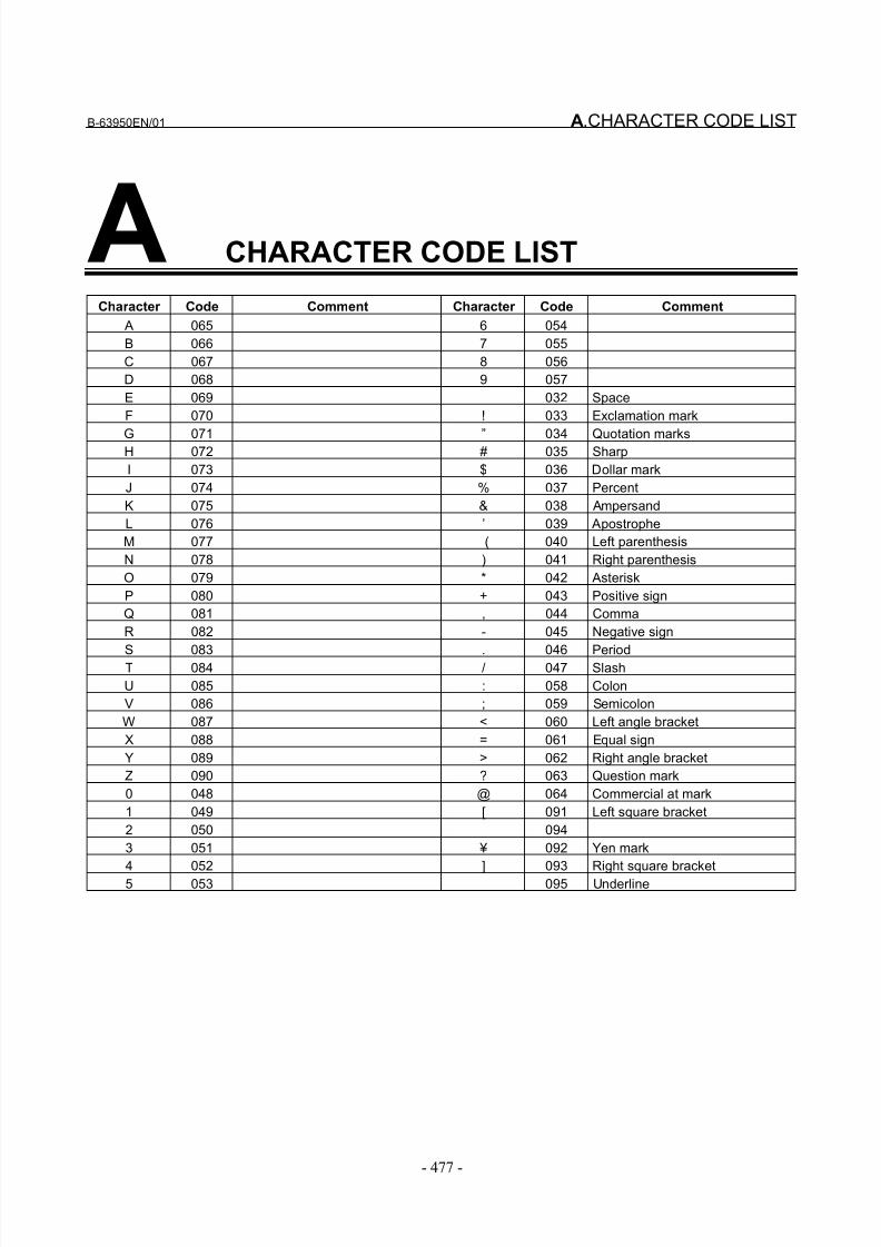
8/21/2019 30i Parameter Manual
http://slidepdf.com/reader/full/30i-parameter-manual 489/493
B-63950EN/01 A.CHARACTER CODE LIST
- 477 -
A CHARACTER CODE LIST
Character Code Comment Character Code Comment
A 065 6 054
B 066 7 055
C 067 8 056
D 068 9 057
E 069 032 Space
F 070 ! 033 Exclamation mark
G 071 ” 034 Quotation marksH 072 # 035 Sharp
I 073 $ 036 Dollar mark
J 074 % 037 Percent
K 075 & 038 Ampersand
L 076 ’ 039 Apostrophe
M 077 ( 040 Left parenthesis
N 078 ) 041 Right parenthesis
O 079 * 042 Asterisk
P 080 + 043 Positive sign
Q 081 , 044 Comma
R 082 - 045 Negative sign
S 083 . 046 PeriodT 084 / 047 Slash
U 085 : 058 Colon
V 086 ; 059 Semicolon
W 087 < 060 Left angle bracket
X 088 = 061 Equal sign
Y 089 > 062 Right angle bracket
Z 090 ? 063 Question mark
0 048 @ 064 Commercial at mark
1 049 [ 091 Left square bracket
2 050 094
3 051 ¥ 092 Yen mark
4 052 ] 093 Right square bracket
5 053 _ 095 Underline

8/21/2019 30i Parameter Manual
http://slidepdf.com/reader/full/30i-parameter-manual 490/493
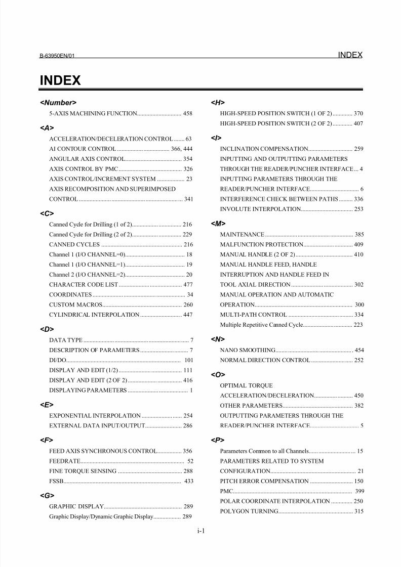
8/21/2019 30i Parameter Manual
http://slidepdf.com/reader/full/30i-parameter-manual 491/493
B-63950EN/01 INDEX
i-1
INDEX
<Number>
5-AXIS MACHINING FUNCTION............................. 458
<A>
ACCELERATION/DECELERATION CONTROL....... 63
AI CONTOUR CONTROL ................. ................. 366, 444
ANGULAR AXIS CONTROL..................................... 354
AXIS CONTROL BY PMC.................... ..................... 326
AXIS CONTROL/INCREMENT SYSTEM .................. 23
AXIS RECOMPOSITION AND SUPERIMPOSED
CONTROL ..................... ...................... ..................... ... 341
<C>
Canned Cycle for Drilling (1 of 2)................. ............... 216
Canned Cycle for Drilling (2 of 2)................. ............... 229
CANNED CYCLES ..................................................... 216
Channel 1 (I/O CHANNEL=0)....................................... 18
Channel 1 (I/O CHANNEL=1)....................................... 19
Channel 2 (I/O CHANNEL=2)....................................... 20
CHARACTER CODE LIST.................... ..................... 477
COORDINATES.................... ..................... ................... 34
CUSTOM MACROS.................................................... 260
CYLINDRICAL INTERPOLATION.......................... . 447
<D>
DATA TYPE .................... ...................... ..................... ..... 7
DESCRIPTION OF PARAMETERS...................... ......... 7
DI/DO........................................................................... 101
DISPLAY AND EDIT (1/2) ..................... .................... 111
DISPLAY AND EDIT (2 OF 2) ................... ................ 416
DISPLAYING PARAMETERS .................... ................... 1
<E>
EXPONENTIAL INTERPOLATION .................... ...... 254
EXTERNAL DATA INPUT/OUTPUT........................ 286
<F>
FEED AXIS SYNCHRONOUS CONTROL................ 356
FEEDRATE.................................................................... 52
FINE TORQUE SENSING .......................................... 288
FSSB............................................................................. 433
<G>GRAPHIC DISPLAY................................................... 289
Graphic Display/Dynamic Graphic Display.................. 289
<H>
HIGH-SPEED POSITION SWITCH (1 OF 2) ............. 370
HIGH-SPEED POSITION SWITCH (2 OF 2) ............. 407
<I>
INCLINATION COMPENSATION............................. 259
INPUTTING AND OUTPUTTING PARAMETERS
THROUGH THE READER/PUNCHER INTERFACE... 4
INPUTTING PARAMETERS THROUGH THE
READER/PUNCHER INTERFACE................................ 6
INTERFERENCE CHECK BETWEEN PATHS......... 336
INVOLUTE INTERPOLATION.................................. 253
<M>
MAINTENANCE..................... ..................... ............... 385
MALFUNCTION PROTECTION.................... ............ 409
MANUAL HANDLE (2 OF 2).................. ................... 410
MANUAL HANDLE FEED, HANDLE
INTERRUPTION AND HANDLE FEED IN
TOOL AXIAL DIRECTION..................... ................... 302
MANUAL OPERATION AND AUTOMATIC
OPERATION................................................................ 300
MULTI-PATH CONTROL ................................. ......... 334
Multiple Repetitive Canned Cycle.................... ............ 223
<N>
NANO SMOOTHING........ .................... ..................... . 454
NORMAL DIRECTION CONTROL...................... ..... 252
<O>
OPTIMAL TORQUE
ACCELERATION/DECELERATION............... .......... 450OTHER PARAMETERS.............................................. 382
OUTPUTTING PARAMETERS THROUGH THE
READER/PUNCHER INTERFACE................................ 5
<P>
Parameters Common to all Channels...... ..................... ... 15
PARAMETERS RELATED TO SYSTEM
CONFIGURATION........................................................ 21
PITCH ERROR COMPENSATION ............................ 150
PMC.............................................................................. 399
POLAR COORDINATE INTERPOLATION .............. 250
POLYGON TURNING................................................. 315
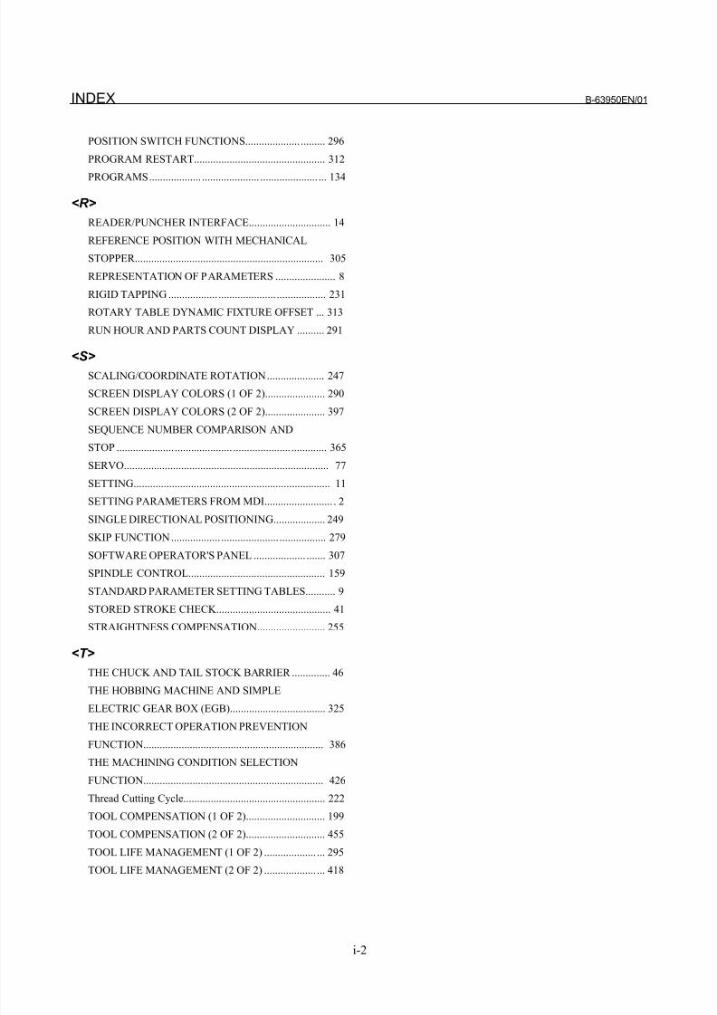
8/21/2019 30i Parameter Manual
http://slidepdf.com/reader/full/30i-parameter-manual 492/493
INDEX B-63950EN/01
i-2
POSITION SWITCH FUNCTIONS.................... ......... 296
PROGRAM RESTART................................................ 312
PROGRAMS................... ..................... ..................... ... 134
<R>
READER/PUNCHER INTERFACE.............................. 14
REFERENCE POSITION WITH MECHANICAL
STOPPER..................................................................... 305
REPRESENTATION OF PARAMETERS ...................... 8
RIGID TAPPING .................. ..................... .................. 231
ROTARY TABLE DYNAMIC FIXTURE OFFSET ... 313
RUN HOUR AND PARTS COUNT DISPLAY .......... 291
<S>
SCALING/COORDINATE ROTATION..................... 247
SCREEN DISPLAY COLORS (1 OF 2)...................... 290
SCREEN DISPLAY COLORS (2 OF 2)...................... 397
SEQUENCE NUMBER COMPARISON AND
STOP ..................... ..................... ..................... ............. 365
SERVO........................................................................... 77
SETTING........................................................................ 11
SETTING PARAMETERS FROM MDI......................... . 2
SINGLE DIRECTIONAL POSITIONING................... 249
SKIP FUNCTION.................. ..................... ................. 279
SOFTWARE OPERATOR'S PANEL ................... ....... 307
SPINDLE CONTROL.................................................. 159
STANDARD PARAMETER SETTING TABLES........... 9
STORED STROKE CHECK.......................................... 41
STRAIGHTNESS COMPENSATION......................... 255
<T>
THE CHUCK AND TAIL STOCK BARRIER .............. 46
THE HOBBING MACHINE AND SIMPLE
ELECTRIC GEAR BOX (EGB)................................... 325THE INCORRECT OPERATION PREVENTION
FUNCTION.................................................................. 386
THE MACHINING CONDITION SELECTION
FUNCTION.................................................................. 426
Thread Cutting Cycle.................................................... 222
TOOL COMPENSATION (1 OF 2)............................. 199
TOOL COMPENSATION (2 OF 2)............................. 455
TOOL LIFE MANAGEMENT (1 OF 2) ................... ... 295
TOOL LIFE MANAGEMENT (2 OF 2) ................... ... 418
8/21/2019 30i Parameter Manual
http://slidepdf.com/reader/full/30i-parameter-manual 493/493
o r d
A R A M E T E R
M A N
U A L ( B - 6 3 9 5 0 E N )
t i o n
D a t e
C o n t e n t s


