24
30XW Water-Cooled Liquid Chiller

CAT_30XW_E-1910_13
CAT_30XW_E-1709_12
Oct, 2019
Version:
Supersede:
Effective date:
The Manufacturer reserves the right to change any produt specifications without prior notices
30XWWater-Cooled Liquid Chiller

In 1998, Time magazine named Dr. Carrier oneof its 20 most influential builders and titans ofthe 20thcentury.
Turn To The ExpertsCarrier is a leading global provider of innovative HVAC, refrigeration, fire, security and building automation technologies.
Supported by the iconic Carrier name, the company’s portfolio includes industry-leading brands such as Carrier, Kidde, Edwards, LenelS2 and Automated Logic.
Carrier’s businesses enable modern life, delivering efficiency, safety, security, comfort, productivity and sustainability across a wide range of residential, com-mercial and industrial applications.
2
Cooling Capacity
250~3467kW
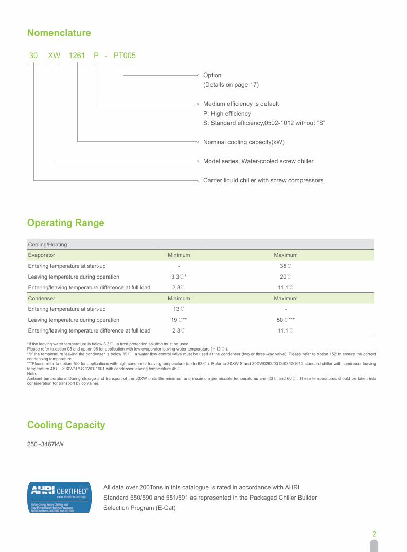
Nomenclature
Option (Details on page 17)
Medium efficiency is defaultP: High efficiencyS: Standard efficiency,0502-1012 without "S"
Nominal cooling capacity(kW)
Model series, Water-cooled screw chiller
Carrier liquid chiller with screw compressors
30 XW 1261 P - PT005
Operating Range
Cooling/Heating
Evaporator Minimum Maximum
Entering temperature at start-up - 35℃
Leaving temperature during operation 3.3℃* 20℃
Entering/leaving temperature difference at full load 2.8℃ 11.1℃
Condenser Minimum Maximum
Entering temperature at start-up 13℃ -
Leaving temperature during operation 19℃** 50℃***
Entering/leaving temperature difference at full load 2.8℃ 11.1℃
*If the leaving water temperature is below 3.3℃ , a frost protection solution must be used.Please refer to option 05 and option 06 for application with low evaporator leaving water temperature (>-12℃ ).**If the temperature leaving the condenser is below 19℃ , a water flow control valve must be used at the condenser (two or three-way valve). Please refer to option 152 to ensure the correct condensing temperature.***Please refer to option 150 for applications with high condenser leaving temperature (up to 63℃ ). Refer to 30XW-S and 30XW0262/0312/0352/1012 standard chiller with condenser leaving temperature 48℃ . 30XW/-P/-S 1261-1601 with condenser leaving temperature 45℃ . Note:Ambient temperature: During storage and transport of the 30XW units the minimum and maximum permissible temperatures are -20℃ and 60℃ . These temperatures should be taken into consideration for transport by container.
All data over 200Tons in this catalogue is rated in accordance with AHRI
Standard 550/590 and 551/591 as represented in the Packaged Chiller Builder
Selection Program (E-Cat)

3
Screw compressors- Industrial-type screw compressors with oversized bearings and motor cooled by suction gas. - Patented line-design screw rotors and microprocessor-based control to guarantee accurate
meshing and enhance service life.- Reduced number of moving parts, with compressor rotors directly driven by the motor, to lower
the gailure rate and enhance reliability.- All compressor components are easily accessible on site minimizing down-time.- Protection increased by an electronic board.Evaporator- Electronic paddle-free flow switch. Auto-setting according to cooler size and fluid type.Auto-adaptive control.- Control algorithm prevents excessive compressor cycling (Carrier patent).- Automatic compressor unloading in case of abnormally high condensing pressure.- Control system has comprehensive protection during operation, such as oil temperature
control, overvoltage and overcurrent protection, discharge temperature overheat protection, heat exchanger anti-freeze protection etc. in order to ensure chiller long time reliable operation.
Exceptional endurance tests- Partnerships with specialized laboratories and use of limit simulation tools (finite element
calculation) for the design of critical components.- Transport simulation test in the laboratory on a vibrating table and then on an endurance
circuit.
Features
Absolute reliability
The Aquaforce liquid chillers are the premium solution for industrial and commercial applications where installers, consultants and building owners require optimal performances and maximum quality.The Aquaforce liquid chillers are designed to meet current and future compactness. They use the most reliable technologies available today:- Twin-rotor screw compressors with a variable capacity valve.- Single refrigerant R134a.- Carrier SmartViewTM Control system.- Flooded heat exchangers that are mechanically cleanable.To meet to all environmental and economic requirements,the 30XW is available in three efficiency classes:- Standard efficiency 30XW-S units that offerings excellent quality with superior cost advantage,
designed to maximize savings, it’s the cost-effective choice, suitable for comfort cooling of hotels, office and industrial settings.
- Medium-efficiency 30XW units that offer an optinized balance of technical and economical aspects, while at the same time boasting superior energy efficiency.
- High-efficiency 30XW-P units that offer unequalled energy efficiency to satisfy the most stringent demands of building owners wanting to reduce operating costs to the minimum.
The 30XW Aquaforce range is also split into two versions:- 30XW for air conditioning and refrigeration applications.- 30XW Heating for heating applications.These two versions provide the following performances:- High heating temperature, allowing the 30XW Heating Aquaforce to supply water with a
condenser leaving water temperature of +63°C (option 150A)- Low temperature, allowing the 30XW Aquaforce to operate with an evaporator leaving glycol
temperature down to -6°C (option 5) or -12°C (option 6).
Premium full load and part load performance
New twin-rotor screw compressor specifically designed for HFC-134a equipped with a high-efficiency motor and a variable capacity valve that permits exact matching of the cooling capacity to the load.Flooded multi-pipe evaporator and condenser for increased heat exchange efficiency. The evaporator has a low pressure drop-which results in reduced cost of water pump.Electronic expansion device permitting operation at a lower condensing pressure and improved utilization of the evaporator heat exchange surface (superheat control).Economizer system with electronic expansion device for increased cooling capacity (30XW-P).

4
Environmental care
R134a refrigerant- Refrigerant of the HFC group with zero ozone depletion potential.Leak-tight refrigerant circuit- Reduction of leaks as no capillary tubes and are connections are used.- Verication of pressure transducers and temperature sensors without trans ferring refrigerant
charge.- Discharge line shut-off valve and liquid line service valve for simplied maintenance.
Compact design- The 30XW units are designed to offer the most compact dimensions on the market.- With a width of approximately 1 m up to 1500 kW the units can pass through standard door
openings and only require minimum oor space in the plant room.Simplied electrical connections- Main disconnect switch with high trip capacity.- Transformer to supply the integrated control circuit (400/24 V).Simplied hydronic connections- Victaulic connections on the evaporator and condenser.- Practical reference marks for entering and leaving water connections.- Possibility to reverse the heat exchanger water inlet and outlet at the factory.Fast commissioning- Systematic factory operation test before shipment.- Quick-test function for step-by-step verication of the instruments, expansion devices and
compressors.
Easy and fast installation
Smart Control
New innovative Carrier SmartViewTM control system combines intelligence with operating simplicity which providing more comfortable operation experience. The control constantly monitors all machine parameters and precisely manages the operation of compressors, electronic expansion devices and of the evaporator water pump for optimum energy efficiency.Ease-of-use- An intuitive and user-friendly interface, the concise and clear information is available in local
languages.- Complete menu which can customized for different users (end user, service personnel or
Carrier engineers).- Graphically dynamic display of the operation parameters in real time.- Up to 10 languages for choice.- The DCT (Data Collection Tool) records the alarms history and automatically pushed alarm
mail to simplify and facilitate service operations.Energy management- Internal time schedule clock: controls chiller on/off times and operation at a second set-point.- Set-point reset based on the return water temperature.- Carrier Smart Service (optional) provides value added customer service which enhanced data
management and analysis will help achieve continuous optimization of the chiller and system operation.

5
30XW chiller employs Carrier’s most advanced Carrier SmartViewTM controller that delivers distinct capabilities of
controlling and monitoring the chiller operations.
Equipped with high-resolution colorful touch screen, Carrier SmartViewTM controller offers more user-friendly interface
with intuitive graphical operational data in real time, adapts precisely the chiller capacity to building load and provides
comprehensive protection.
Carrier SmartViewTM Control System - Intelligent Colored Touch Screen
Carrier SmartViewTM controller offers password protection to avoid any unauthorized operation.
When chiller starts, the controller will activate pre-start process to check parameters such as pressure, temperature,
motor status, water flow etc.
In addition to the function of monitoring the main operational parameters, trending function provide the visual dynamic
parameter curves. The intelligent and dynamic algorithm ensures optimal, effective and reliable chiller operation.
The control system provides following comprehensive protection, which guarantees steady chiller operation:
- Overcurrent.
- Discharge temperature overheat.
- Motor temperature overheat.
- Evaporator and condenser anti-freeze.
- Low discharge superheat.
Reliable Start - up and Operation
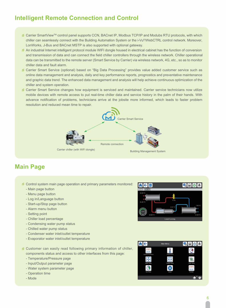
Carrier SmartViewTM control panel supports CCN, BACnet IP, Modbus TCP/IP and Modubs RTU protocols, with which chiller can seamlessly connect with the Building Automation System or the i-Vu®/WebCTRL control network. Moreover, LonWorks, J-Bus and BACnet MSTP is also supported with optional gateway.An industrial Internet intelligent protocol module WIFI dongle housed in electrical cabinet has the function of conversion and transmission of data and can connect the field chiller controllers through the wireless network. Chiller operational data can be transmitted to the remote server (Smart Service by Carrier) via wireless network, 4G, etc., so as to monitor chiller data and fault alarm.Carrier Smart Service (optional) based on “Big Data Processing” provides value added customer service such as online data management and analysis, daily and key performance reports, prognostics and preventative maintenance and graphic data trend. The enhanced data management and analysis will help achieve continuous optimization of the chiller and system operation.Carrier Smart Service changes how equipment is serviced and maintained. Carrier service technicians now utilize mobile devices with remote access to put real-time chiller data and service history in the palm of their hands. With advance notification of problems, technicians arrive at the jobsite more informed, which leads to faster problem resolution and reduced mean time to repair.
Intelligent Remote Connection and Control
Carrier SmartViewTM control system has more than 100 failure diagnostic function. Users can easily access chiller
operation parameters via touch screen. If control system detects failure the alarm will be initiated and related code will
be recorded in alarm menu. The alarm records, up to 50, can be automatically saved by control system. Carrier service
technician can read and delete alarm records by Carrier service/PCDCT tools.
The control system can automatically send out email alarm to customer or service technician.
Effective Failure Diagnostic
Remote connection
Building Management SystemCarrier chiller (with WiFi dongle)
Carrier Smart ServiceCa
Control system main page operation and primary parameters monitored:- Main page button- Menu page button- Log in/Language button- Start-up/Stop page button- Alarm menu button- Setting point- Chiller load percentage- Condensing water pump status- Chilled water pump status- Condenser water inlet/outlet temperature- Evaporator water inlet/outlet temperature
Customer can easily read following primary information of chiller, components status and access to other interfaces from this page:- Temperature/Pressure page- Input/Output parameter page- Water system parameter page- Operation time- Mode
Main Page
6
30XW chiller employs Carrier’s most advanced Carrier SmartViewTM controller that delivers distinct capabilities of
controlling and monitoring the chiller operations.
Equipped with high-resolution colorful touch screen, Carrier SmartViewTM controller offers more user-friendly interface
with intuitive graphical operational data in real time, adapts precisely the chiller capacity to building load and provides
comprehensive protection.
Carrier SmartViewTM Control System - Intelligent Colored Touch Screen
Carrier SmartViewTM controller offers password protection to avoid any unauthorized operation.
When chiller starts, the controller will activate pre-start process to check parameters such as pressure, temperature,
motor status, water flow etc.
In addition to the function of monitoring the main operational parameters, trending function provide the visual dynamic
parameter curves. The intelligent and dynamic algorithm ensures optimal, effective and reliable chiller operation.
The control system provides following comprehensive protection, which guarantees steady chiller operation:
- Overcurrent.
- Discharge temperature overheat.
- Motor temperature overheat.
- Evaporator and condenser anti-freeze.
- Low discharge superheat.
Reliable Start - up and Operation
Carrier SmartViewTM control panel supports CCN, BACnet IP, Modbus TCP/IP and Modubs RTU protocols, with which chiller can seamlessly connect with the Building Automation System or the i-Vu®/WebCTRL control network. Moreover, LonWorks, J-Bus and BACnet MSTP is also supported with optional gateway.An industrial Internet intelligent protocol module WIFI dongle housed in electrical cabinet has the function of conversion and transmission of data and can connect the field chiller controllers through the wireless network. Chiller operational data can be transmitted to the remote server (Smart Service by Carrier) via wireless network, 4G, etc., so as to monitor chiller data and fault alarm.Carrier Smart Service (optional) based on “Big Data Processing” provides value added customer service such as online data management and analysis, daily and key performance reports, prognostics and preventative maintenance and graphic data trend. The enhanced data management and analysis will help achieve continuous optimization of the chiller and system operation.Carrier Smart Service changes how equipment is serviced and maintained. Carrier service technicians now utilize mobile devices with remote access to put real-time chiller data and service history in the palm of their hands. With advance notification of problems, technicians arrive at the jobsite more informed, which leads to faster problem resolution and reduced mean time to repair.
Intelligent Remote Connection and Control
Carrier SmartViewTM control system has more than 100 failure diagnostic function. Users can easily access chiller
operation parameters via touch screen. If control system detects failure the alarm will be initiated and related code will
be recorded in alarm menu. The alarm records, up to 50, can be automatically saved by control system. Carrier service
technician can read and delete alarm records by Carrier service/PCDCT tools.
The control system can automatically send out email alarm to customer or service technician.
Effective Failure Diagnostic
Remote connection
Building Management SystemCarrier chiller (with WiFi dongle)
Carrier Smart ServiceCa
Control system main page operation and primary parameters monitored:- Main page button- Menu page button- Log in/Language button- Start-up/Stop page button- Alarm menu button- Setting point- Chiller load percentage- Condensing water pump status- Chilled water pump status- Condenser water inlet/outlet temperature- Evaporator water inlet/outlet temperature
Customer can easily read following primary information of chiller, components status and access to other interfaces from this page:- Temperature/Pressure page- Input/Output parameter page- Water system parameter page- Operation time- Mode
Main Page

7
Operation condition: Evaporator leaving water temperature 6.7℃, water flow rate per capacity is 0.043 l/s·kW, fouling factor=0.018m2K/kW Condenser entering water temperature 29.4℃, water flow rate per capacity is 0.054 l/s·kW, fouling factor=0.044m2K/kWAbove are recommended models. Carrier can offer more models and computer selections at required conditions. For details, please contact Carrier local agencies.*The shipment weight is only base unit and wooden crating, excluding refrigerant and water inside.
Performance data 30XW-P
Model
30XW-P
0312P0352P0452P0532P 0552P 0612P0652P0702P 0802P 0852P 0912P 1002P 1052P 1152P 1261P1351P1401P1501P1601P1712P1762P
Capacity
kW 303.5 366.3 448.5 536.1 571.8 640.1 675.8 729.7 785.0 852.3 897.5 974.0 1075.0 1147.0 1245.0 1340.0 1410.0 1489.0 1589.0 1747.0 1762.0
USRT 86 104 128 152 163 182 192 208 223 242 255 277 306 326 354 381 401 423 452 497 501
COP kW/kW 5.65 5.65 5.73 6.00 6.02 6.00 6.12 6.06 5.99 5.90 6.00 5.99 5.99 5.98 6.28 6.34 6.33 6.34 6.37 6.17 6.31
Evaporator
Flow rate L/s 13.1 15.8 19.3 23.1 24.6 27.5 29.1 31.4 33.8 36.7 38.6 41.9 46.2 49.3 53.5 57.6 60.6 64.0 68.3 75.1 75.8
Water Pressure drop
kPa 24.9 32.6 29.9 24.6 26.2 39.6 39.6 24.8 28.2 33.5 61.5 50.0 72.5 46.9 49.2 56.6 59.6 64.5 68.0 74.6 49.6
Water connection
DN 125 125 125 150 150 200 200 200 200 200 200 200 200 200 200 200 200 200 200 250 250
Condenser
Flow rate L/s 16.3 19.6 24.3 28.7 30.7 34.6 36.4 39.2 42.1 45.8 47.9 52.4 58.1 62.0 66.9 71.9 75.7 79.9 85.5 94.1 94.8
Water Pressure drop
kPa 51.8 66.8 41.5 38.6 43.1 34.6 40.7 34.1 38.9 46.4 33.9 26.8 34.0 36.8 43.4 49.5 51.8 60.1 68.8 61.2 41.2
Water connection
DN 125 125 125 150 150 200 200 200 200 200 200 200 200 200 200 200 200 200 200 250 250
Compressor
Circuit A No. 1 1 1 1 1 1 1 1 1 1 1 1 1 1 1 1 1 1 1 1 1
Circuit B No. - - - - - - - - - - - 1 1 1 - - - - - 1 1
Min. capacity % 15 15 15 15 15 15 15 15 15 15 15 8 8 8 20 20 20 20 15 8 8
Motor
Power V-Ph-Hz 400-3-50
Input power kW 53.8 64.8 78.3 89.4 94.9 106.6 110.4 120.5 131.0 144.5 149.6 162.5 179.6 191.9 198.3 211.3 222.8 234.9 249.5 283.3 279.3
Refrigerant Charge
HFC-134a
Circuit A kg 78 78 100 135 135 176 176 200 200 200 233 115 115 130 365 365 365 365 365 187.5 250
Circuit B kg - - - - - - - - - - - 125 125 140 - - - - - 187.5 250
Shipping weight* kg 2301 2336 2866 3137 3177 4032 4012 4131 4149 4179 4260 5998 6067 6479 8114 8114 8165 8243 8333 9043 10348
Operation weight kg 2083 2118 2600 2994 3025 3999 3979 4155 4173 4204 4299 6069 6112 6684 8230 8230 8280 8355 8443 9368 10948
Dimension
Length mm 2740 2740 2763 3055 3055 3101 3080 3286 3286 3286 3142 4695 4695 4694 4515 4515 4515 4515 4515 4783 4809
Width mm 960 960 970 1008 1008 1135 1135 1135 1135 1135 1070 1070 1070 1070 1541 1541 1541 1541 1541 1985 2160
Height mm 1568 1568 1696 1743 1743 1950 1950 1949 1949 1949 2062 1947 1947 1998 2614 2614 2614 2614 2614 1520 1586

8
Operation condition: Evaporator leaving water temperature 6.7℃, water flow rate per capacity is 0.043 l/s·kW, fouling factor=0.018m2K/kW Condenser entering water temperature 29.4℃, water flow rate per capacity is 0.054 l/s·kW, fouling factor=0.044m2K/kWAbove are recommended models. Carrier can offer more models and computer selections at required conditions. For details, please contact Carrier local agencies.*The shipment weight is only base unit and wooden crating, excluding refrigerant and water inside.
Performance data 30XW
Model
30XW
0262 0312 0352 0412 0422 0452 0552 0622 0652 0702 0812 0852 0902 0922
Capacity
kW 249.5 303.6 366.9 424.0 452.7 468.9 540.2 621.0 662.3 715.3 784.5 826.1 852.4 890.6
USRT 71 86 104 121 129 133 154 177 188 203 223 235 242 253
COP kW/kW 5.28 5.31 5.30 5.29 5.29 5.45 5.59 5.60 5.51 5.61 5.60 5.52 5.83 5.66
Evaporator
Flow rate L/s 10.7 13.1 15.8 18.2 19.5 20.2 23.2 26.7 28.5 30.8 33.7 35.5 36.7 38.3
Water Pressure
dropkPa 16.4 22.8 29.5 34.5 36.7 27.6 36.1 34.0 33.7 38.3 39.9 48.3 54.3 62.2
Water connection
DN 125 125 125 125 125 125 125 150 150 150 200 150 150 200
Condenser
Flow rate L/s 13.5 16.4 19.6 22.7 24.4 25.1 28.9 33.3 35.4 38.1 41.8 44.4 45.7 47.8
Water Pressure
dropkPa 32.4 43.4 54.6 34.7 36.4 36.4 46.1 47.0 51.8 54.3 29.6 36.2 42.2 50.6
Water connection
DN 125 125 125 125 125 125 125 150 150 150 200 200 200 200
Compressor
Circuit A No. 1 1 1 1 1 1 1 1 1 1 1 1 1 1
Circuit B No. - - - - - - - - - - - - - -
Min. capacity % 15 15 15 15 15 15 15 15 15 15 15 15 15 15
Motor
Power V-Ph-Hz 400-3-50
Input power kW 47.2 57.2 69.2 80.1 85.6 86.1 96.6 110.8 120.3 127.6 140.2 149.7 146.1 157.4
Refrigerant Charge
HFC-134a
Circuit A kg 78 78 78 100 85 100 110 150 150 140 160 150 150 176
Circuit B kg - - - - - - - - - - - - - -
Shipping weight* kg 2220 2281 2316 2692 2707 2846 2934 3637 3620 3647 3774 3808 3827 4012
Operation weight kg 2002 2063 2098 2518 2518 2580 2684 3509 3486 3509 3688 3711 3923 3979
Dimension
Length mm 2742 2742 2742 2746 2746 2746 2763 3084 3056 3084 2780 2780 3080 3080
Width mm 960 960 960 970 970 970 970 1119 1119 1119 1085 1085 1135 1135
Height mm 1568 1568 1568 1694 1694 1693 1693 1873 1849 1873 1950 1900 1900 1950

9
Model
30XW
1002 1052 1152 1261 1351 1401 1501 1601 1712 1762 2052 2302 2602 2902 3052 3302 3452
Capacity
kW 1003.0 1075.0 1135.0 1258.0 1327.0 1434.0 1498.0 1589.0 1709.0 1745.0 2037.0 2288.0 2594.0 2887.0 3046.0 3323.0 3467.0
USRT 285 306 323 357 377 407 426 451 486 496 579 651 738 821 866 945 986
COP kW/kW 5.60 5.64 5.64 5.88 5.88 5.93 5.93 5.90 5.75 5.80 5.83 5.83 5.87 5.90 5.83 5.83 5.83
Evaporator
Flow rate L/s 43.1 46.2 48.8 54.1 57.1 61.6 64.4 68.3 73.5 75.0 87.6 98.4 111.6 124.1 131.0 142.9 149.1
Water Pressure
dropkPa 55.9 68.0 54.4 36.9 39.5 52.5 51.7 58.3 80.8 61.4 68.7 67.3 66.9 72.2 79.8 82.9 85.4
Water connection
DN 150 150 200 200 200 200 200 200 200 200 200 200 300 300 300 300 300
Condenser
Flow rate L/s 54.0 58.0 61.4 67.7 71.4 76.6 80.1 85.1 91.9 93.3 109.2 123.9 140.5 156.0 164.7 179.1 186.7
Water Pressure
dropkPa 33.2 43.4 41.2 38.6 40.5 56.8 52.1 62.7 61.9 58.3 58.3 52.6 60.4 52.4 58.6 62.0 66.6
Water connection
DN 200 200 200 200 200 200 200 200 200 200 250 250 300 300 300 300 300
Compressor
Circuit A No. 1 1 1 1 1 1 1 1 1 1 1/1 1/1 1/1 1/1 1/1 1/1 1/1
Circuit B No. 1 1 1 - - - - - 1 1 1/1 1/1 1/1 1/1 1/1 1/1 1/1
Min. capacity
% 8 8 8 20 20 20 20 15 15 8 4 4 4 4 4 4 4
Motor
Power V-Ph-Hz 400-3-50
Input power
kW 179.0 190.7 201.1 214.0 225.8 241.9 252.7 269.2 297.3 301.0 349.3 392.3 442.2 489.2 522.3 570.0 594.9
Refrigerant Charge
HFC-134a
Circuit A kg 85 85 100 300 300 340 350 360 140 140 85/85 100/100 130/130 130/130 130/130 140/140 140/140
Circuit B kg 95 95 110 - - - - - 160 160 95/95 110/110 140/140 140/140 140/140 160/160 160/160
Shipping weight* kg 5334 5349 5571 7312 7358 7704 7736 7831 9073 8994 10886 11454 14338 15494 15454 18667 18695
Operation weight kg 5255 5259 5553 7296 7341 7717 7781 7883 8953 8934 10870 11648 14842 16140 16100 18729 18757
Dimension
Length mm 4008 4029 4008 4088 4088 4488 4488 4488 4761 4787 4593 4602 5321 5359 5358 5422 5422
Width mm 1050 1050 1050 1526 1526 1526 1526 1524 1338 1258 2570 2570 2846 2932 2932 3066 3066
Height mm 1845 1845 1896 2563 2563 2563 2563 2563 2307 2307 1846 1896 2064 2064 2064 2307 2307
Performance data 30XW
Operation condition: Evaporator leaving water temperature 6.7℃, water flow rate per capacity is 0.043 l/s·kW, fouling factor=0.018m2K/kW Condenser entering water temperature 29.4℃, water flow rate per capacity is 0.054 l/s·kW, fouling factor=0.044m2K/kWAbove are recommended models. Carrier can offer more models and computer selections at required conditions. For details, please contact Carrier local agencies.*The shipment weight is only base unit and wooden crating, excluding refrigerant and water inside.
10
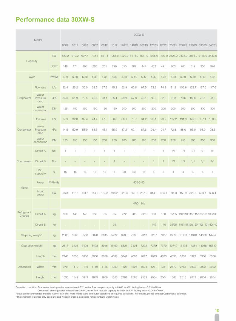
Model
30XW-S
0502 0612 0692 0802 0912 1012 1261S 1401S 1601S 1712S 1762S 2052S 2602S 2902S 3302S 3452S
Capacity
kW 520.2 610.2 697.4 772.1 881.4 1051.0 1229.0 1414.0 1571.0 1696.0 1727.0 2121.0 2478.0 2854.0 3185.0 3433.0
USRT 148 174 198 220 251 299 350 402 447 482 491 603 705 812 906 976
COP kW/kW 5.29 5.30 5.30 5.33 5.35 5.30 5.38 5.44 5.47 5.40 5.35 5.38 5.39 5.39 5.40 5.48
Evaporator
Flow rate L/s 22.4 26.2 30.0 33.2 37.9 45.2 52.9 60.8 67.5 72.9 74.3 91.2 106.6 122.7 137.0 147.6
Water Pressure
dropkPa 34.6 61.9 72.5 45.6 58.1 55.4 59.9 57.8 48.1 80.0 82.9 61.8 70.6 87.8 73.1 88.5
Water connection
DN 125 150 150 150 150 150 200 200 200 200 200 200 200 300 300 300
Condenser
Flow rate L/s 27.9 32.8 37.4 41.4 47.0 56.6 66.1 75.7 84.2 92.1 93.2 112.2 131.3 149.8 167.4 180.5
Water Pressure
dropkPa 44.5 50.9 58.9 68.5 45.1 65.9 47.2 69.1 67.6 91.4 94.7 72.8 88.0 93.0 93.0 98.6
Water connection
DN 125 150 150 150 200 200 200 200 200 200 200 250 250 300 300 300
Compressor
Circuit A No. 1 1 1 1 1 1 1 1 1 1 1 1/1 1/1 1/1 1/1 1/1
Circuit B No. - - - - - 1 - - - 1 1 1/1 1/1 1/1 1/1 1/1
Min. capacity
% 15 15 15 15 15 8 20 20 15 8 8 4 4 4 4 4
Motor
Power V-Ph-Hz 400-3-50
Input power
kW 98.3 115.1 131.5 144.9 164.8 198.2 228.3 260.0 287.2 314.0 323.1 394.3 459.9 529.8 590.1 626.4
Refrigerant Charge
HFC-134a
Circuit A kg 100 140 140 150 155 85 272 285 320 130 130 85/85 110/110 115/115 130/130 130/130
Circuit B kg - - - - - 95 - - - 140 140 95/95 115/115 120/120 140/140 140/140
Shipping weight* kg 2883 3560 3560 3628 3845 5222 6705 7203 7312 7207 7207 10835 13153 14040 14370 14752
Operation weight kg 2617 3426 3426 3493 3946 5109 6521 7101 7292 7379 7379 10740 13193 14354 14958 15340
Dimension
Length mm 2746 3056 3056 3056 3080 4008 3947 4097 4097 4693 4693 4591 5251 5329 5356 5356
Width mm 970 1119 1119 1119 1135 1050 1526 1526 1524 1231 1231 2570 2761 2932 2932 2932
Height mm 1693 1849 1849 1849 1900 1846 2481 2563 2563 2064 2064 1846 2013 2013 2064 2064
Performance data 30XW-S
Operation condition: Evaporator leaving water temperature 6.7℃, water flow rate per capacity is 0.043 l/s·kW, fouling factor=0.018m2K/kW Condenser entering water temperature 29.4℃, water flow rate per capacity is 0.054 l/s·kW, fouling factor=0.044m2K/kWAbove are recommended models. Carrier can offer more models and computer selections at required conditions. For details, please contact Carrier local agencies.*The shipment weight is only base unit and wooden crating, excluding refrigerant and water inside.
11
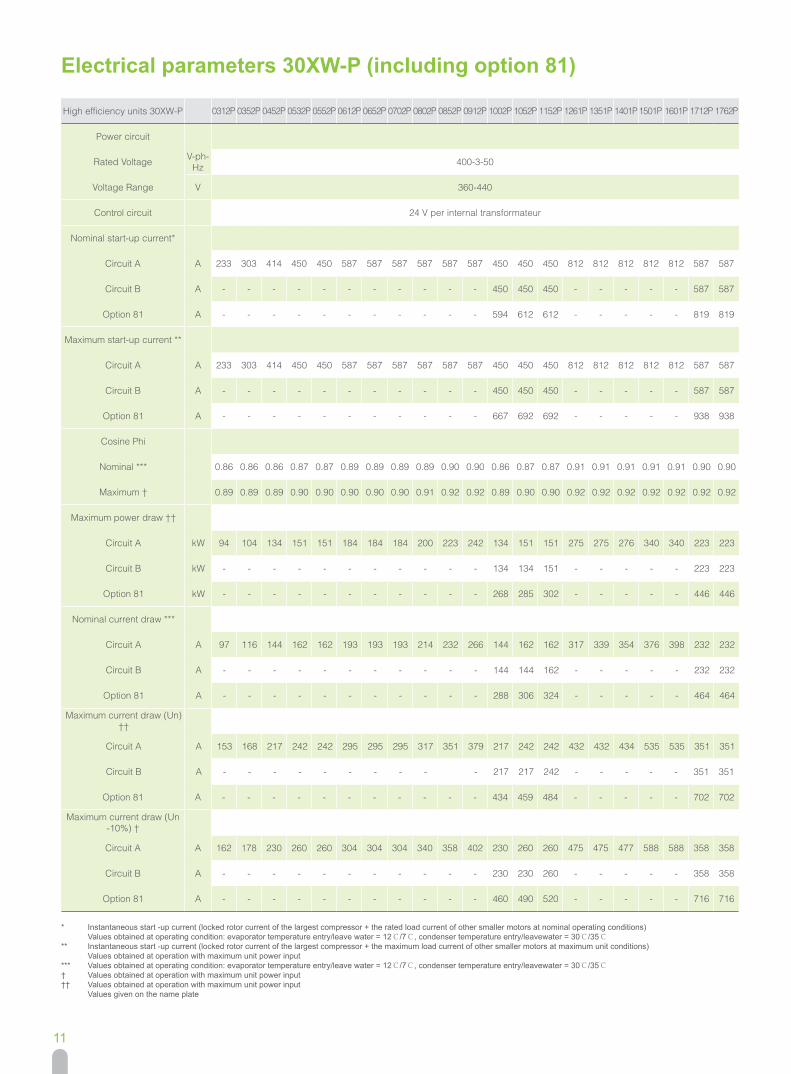
Electrical parameters 30XW-P (including option 81)
* Instantaneous start -up current (locked rotor current of the largest compressor + the rated load current of other smaller motors at nominal operating conditions) Values obtained at operating condition: evaporator temperature entry/leave water = 12℃/7℃, condenser temperature entry/leavewater = 30℃/35℃ ** Instantaneous start -up current (locked rotor current of the largest compressor + the maximum load current of other smaller motors at maximum unit conditions) Values obtained at operation with maximum unit power input *** Values obtained at operating condition: evaporator temperature entry/leave water = 12℃/7℃, condenser temperature entry/leavewater = 30℃/35℃ † Values obtained at operation with maximum unit power input †† Values obtained at operation with maximum unit power input Values given on the name plate
High efficiency units 30XW-P 0312P 0352P 0452P 0532P 0552P 0612P 0652P 0702P 0802P 0852P 0912P 1002P 1052P 1152P 1261P 1351P 1401P 1501P 1601P 1712P 1762P
Power circuit
Rated VoltageV-ph-
Hz400-3-50
Voltage Range V 360-440
Control circuit 24 V per internal transformateur
Nominal start-up current*
Circuit A A 233 303 414 450 450 587 587 587 587 587 587 450 450 450 812 812 812 812 812 587 587
Circuit B A - - - - - - - - - - - 450 450 450 - - - - - 587 587
Option 81 A - - - - - - - - - - - 594 612 612 - - - - - 819 819
Maximum start-up current **
Circuit A A 233 303 414 450 450 587 587 587 587 587 587 450 450 450 812 812 812 812 812 587 587
Circuit B A - - - - - - - - - - - 450 450 450 - - - - - 587 587
Option 81 A - - - - - - - - - - - 667 692 692 - - - - - 938 938
Cosine Phi
Nominal *** 0.86 0.86 0.86 0.87 0.87 0.89 0.89 0.89 0.89 0.90 0.90 0.86 0.87 0.87 0.91 0.91 0.91 0.91 0.91 0.90 0.90
Maximum † 0.89 0.89 0.89 0.90 0.90 0.90 0.90 0.90 0.91 0.92 0.92 0.89 0.90 0.90 0.92 0.92 0.92 0.92 0.92 0.92 0.92
Maximum power draw ††
Circuit A kW 94 104 134 151 151 184 184 184 200 223 242 134 151 151 275 275 276 340 340 223 223
Circuit B kW - - - - - - - - - - - 134 134 151 - - - - - 223 223
Option 81 kW - - - - - - - - - - - 268 285 302 - - - - - 446 446
Nominal current draw ***
Circuit A A 97 116 144 162 162 193 193 193 214 232 266 144 162 162 317 339 354 376 398 232 232
Circuit B A - - - - - - - - - - - 144 144 162 - - - - - 232 232
Option 81 A - - - - - - - - - - - 288 306 324 - - - - - 464 464
Maximum current draw (Un) ††
Circuit A A 153 168 217 242 242 295 295 295 317 351 379 217 242 242 432 432 434 535 535 351 351
Circuit B A - - - - - - - - - - 217 217 242 - - - - - 351 351
Option 81 A - - - - - - - - - - - 434 459 484 - - - - - 702 702
Maximum current draw (Un -10%) †
Circuit A A 162 178 230 260 260 304 304 304 340 358 402 230 260 260 475 475 477 588 588 358 358
Circuit B A - - - - - - - - - - - 230 230 260 - - - - - 358 358
Option 81 A - - - - - - - - - - - 460 490 520 - - - - - 716 716

12
Electrical parameters 30XW (including option 81)
* Instantaneous start -up current (locked rotor current of the largest compressor + the rated load current of other smaller motors at nominal operating conditions) Values obtained at operating condition: evaporator temperature entry/leave water = 12℃/7℃, condenser temperature entry/leavewater = 30℃/35℃ ** Instantaneous start -up current (locked rotor current of the largest compressor + the maximum load current of other smaller motors at maximum unit conditions) Values obtained at operation with maximum unit power input *** Values obtained at operating condition: evaporator temperature entry/leave water = 12℃/7℃, condenser temperature entry/leavewater = 30℃/35℃ † Values obtained at operation with maximum unit power input †† Values obtained at operation with maximum unit power input Values given on the name plate
Medium efficiency units 30XW 0262 0312 0352 0412 0422 0452 0552 0622 0652 0702 0812 0852 0902 0922
Power circuit
Rated VoltageV-ph-Hz
400-3-50
Voltage Range V 360-440
Control circuit 24 V per internal transformateur
Nominal start-up current*
Circuit A A 233 233 303 414 414 414 450 587 587 587 587 587 587 587
Circuit B A - - - - - - - - - - - - - -
Option 81 A - - - - - - - - - - - - - -
Maximum start-up current **
Circuit A A 233 233 303 414 414 414 450 587 587 587 587 587 587 587
Circuit B A - - - - - - - - - - - - - -
Option 81 A - - - - - - - - - - - - - -
Cosine Phi
Nominal *** 0.86 0.86 0.86 0.86 0.86 0.86 0.87 0.88 0.88 0.89 0.90 0.90 0.90 0.90
Maximum † 0.89 0.89 0.89 0.89 0.89 0.89 0.90 0.90 0.90 0.91 0.92 0.92 0.92 0.92
Maximum power draw ††
Circuit A kW 80 94 104 134 134 134 151 184 184 200 223 223 223 242
Circuit B kW - - - - - - - - - - - - - -
Option 81 kW - - - - - - - - - - - - - -
Nominal current draw ***
Circuit A A 81 97 116 144 144 144 162 193 193 214 232 232 232 266
Circuit B A - - - - - - - - - - - - - -
Option 81 A - - - - - - - - - - - - - -
Maximum current draw (Un) ††
Circuit A A 130 153 168 217 217 217 242 295 295 317 351 351 351 379
Circuit B A - - - - - - - - - - - - - -
Option 81 A - - - - - - - - - - - - - -
Maximum current draw (Un -10%) †
Circuit A A 138 162 178 230 230 230 260 304 304 340 358 358 358 402
Circuit B A - - - - - - - - - - - - - -
Option 81 A - - - - - - - - - - - - - -

13
Electrical parameters 30XW (including option 81)
* Instantaneous start -up current (locked rotor current of the largest compressor + the rated load current of other smaller motors at nominal operating conditions) Values obtained at operating condition: evaporator temperature entry/leave water = 12℃/7℃, condenser temperature entry/leavewater = 30℃/35℃ ** Instantaneous start -up current (locked rotor current of the largest compressor + the maximum load current of other smaller motors at maximum unit conditions) Values obtained at operation with maximum unit power input *** Values obtained at operating condition: evaporator temperature entry/leave water = 12℃/7℃, condenser temperature entry/leavewater = 30℃/35℃ † Values obtained at operation with maximum unit power input †† Values obtained at operation with maximum unit power input Values given on the name plate
Standard efficiency units 30XW
1002 1052 1152 1261 1351 1401 1501 1601 1712 1762
Power circuit
Rated VoltageV-ph-
Hz400-3-50
Voltage Range V 360-440
Control circuit 24 V per internal transformateur
Nominal start-up current*
Circuit A A 450 450 414 812 812 812 812 812 587 587
Circuit B A 450 450 414 - - - - - 587 587
Option 81 A 612 612 576 - - - - - 819 853
Maximum start-up current **
Circuit A A 450 450 414 812 812 812 812 812 587 587
Circuit B A 450 450 414 - - - - - 587 587
Option 81 A 692 692 656 - - - - - 938 966
Cosine Phi
Nominal *** 0.87 0.87 0.87 0.91 0.91 0.91 0.91 0.91 0.90 0.90
Maximum † 0.90 0.90 0.90 0.92 0.92 0.92 0.92 0.92 0.92 0.92
Maximum power draw ††
Circuit A kW 151 151 151 275 276 340 340 340 223 242
Circuit B kW 134 151 151 - - - - - 223 223
Option 81 kW 285 302 302 - - - - - 446 465
Nominal current draw ***
Circuit A A 162 162 162 343 362 387 404 433 232 266
Circuit B A 144 162 162 - - - - - 232 232
Option 81 A 306 324 324 - - - - - 464 498
Maximum current draw (Un) ††
Circuit A A 242 242 242 432 434 535 535 535 351 379
Circuit B A 217 242 242 - - - - - 351 351
Option 81 A 459 484 484 - - - - - 702 730
Maximum current draw (Un -10%) †
Circuit A A 260 260 260 475 477 588 588 588 358 402
Circuit B A 230 260 260 - - - - - 358 358
Option 81 A 490 520 520 - - - - - 716 760

14
Electrical parameters 30XW (including option 81)
* Instantaneous start -up current (locked rotor current of the largest compressor + the rated load current of other smaller motors at nominal operating conditions) Values obtained at operating condition: evaporator temperature entry/leave water = 12℃/7℃, condenser temperature entry/leavewater = 30℃/35℃ ** Instantaneous start -up current (locked rotor current of the largest compressor + the maximum load current of other smaller motors at maximum unit conditions) Values obtained at operation with maximum unit power input *** Values obtained at operating condition: evaporator temperature entry/leave water = 12℃/7℃, condenser temperature entry/leavewater = 30℃/35℃ † Values obtained at operation with maximum unit power input †† Values obtained at operation with maximum unit power input Values given on the name plate
Medium efficiency units 30XW 2052 2302 2602 2902 3052 3302 3452
Power circuit
Rated VoltageV-ph-
Hz400-3-50
Voltage Range V 360-440
Control circuit 24 V per internal transformateur
Nominal start-up current*
Module1 Circuit A A 414 414 587 587 587 587 587
Module1 Circuit B A 414 414 414 587 587 587 587
Module1 Option 81 A 576 576 749 780 801 819 819
Module2 Circuit A A 414 414 587 587 587 587 587
Module2 Circuit B A 414 414 414 587 587 587 587
Module2 Option 81 A 576 576 749 780 801 819 819
Maximum start-up current **
Module1 Circuit A A 414 414 587 587 587 587 587
Module1 Circuit B A 414 414 414 587 587 587 587
Module1 Option 81 A 656 656 829 882 904 938 938
Module2 Circuit A A 414 414 587 587 587 587 587
Module2 Circuit B A 414 414 414 587 587 587 587
Module2 Option 81 A 656 656 829 882 904 938 938
Cosine Phi
Nominal *** 0.87 0.87 0.88 0.88 0.88 0.90 0.90
Maximum † 0.90 0.90 0.90 0.90 0.90 0.92 0.92
Maximum power draw ††
Module1 Circuit A kW 151 151 184 184 200 223 223
Module1 Circuit B kW 134 151 151 184 184 202 223
Module1 Option 81 kW 285 302 335 368 384 425 446
Module2 Circuit A kW 151 151 184 184 200 223 223
Module2 Circuit B kW 134 151 151 184 184 202 223
Module2 Option 81 kW 285 302 335 368 384 425 446
Nominal current draw ***
Module1 Circuit A A 162 162 193 193 214 232 232
Module1 Circuit B A 144 162 162 193 193 214 232
Module1 Option 81 A 306 324 355 386 407 446 464
Module2 Circuit A A 162 162 193 193 214 232 232
Module2 Circuit B A 144 162 162 193 193 214 232
Module2 Option 81 A 306 324 355 386 407 446 464
Maximum current draw (Un) ††
Module1 Circuit A A 242 242 295 295 317 351 351
Module1 Circuit B A 217 242 242 295 295 317 351
Module1 Option 81 A 459 484 537 590 612 668 702
Module2 Circuit A A 242 242 295 295 317 351 351
Module2 Circuit B A 217 242 242 295 295 317 351
Module2 Option 81 A 459 484 537 590 612 668 702
Maximum current draw (Un -10%) †
Module1 Circuit A A 260 260 304 304 340 358 358
Module1 Circuit B A 230 260 260 304 304 340 358
Module1 Option 81 A 490 520 564 608 644 698 716
Module2 Circuit A A 260 260 304 304 340 358 358
Module2 Circuit B A 230 260 260 304 304 340 358
Module2 Option 81 A 490 520 564 608 644 698 716
15
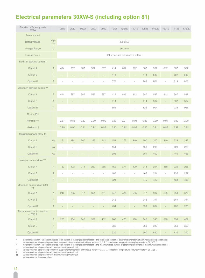
Electrical parameters 30XW-S (including option 81)Standard efficiency units
30XW0502 0612 0692 0802 0912 1012 1261S 1401S 1262S 1402S 1601S 1712S 1762S
Power circuit
Rated VoltageV-ph-Hz
400-3-50
Voltage Range V 360-440
Control circuit 24 V per internal transformateur
Nominal start-up current*
Circuit A A 414 587 587 587 587 414 812 812 587 587 812 587 587
Circuit B A - - - - - 414 - - 414 587 - 587 587
Option 81 A - - - - - 576 - - 749 801 - 819 853
Maximum start-up current **
Circuit A A 414 587 587 587 587 414 812 812 587 587 812 587 587
Circuit B A - - - - - 414 - - 414 587 - 587 587
Option 81 A - - - - - 656 - - 829 904 - 938 966
Cosine Phi
Nominal *** 0.87 0.88 0.89 0.90 0.90 0.87 0.91 0.91 0.88 0.89 0.91 0.90 0.90
Maximum † 0.90 0.90 0.91 0.92 0.92 0.90 0.92 0.92 0.90 0.91 0.92 0.92 0.92
Maximum power draw ††
Circuit A kW 151 184 200 223 242 151 275 340 200 200 340 223 242
Circuit B kW - - - - - 151 - - 151 200 - 223 223
Option 81 kW - - - - - 302 - - 351 400 - 446 465
Nominal current draw ***
Circuit A A 162 193 214 232 266 162 371 420 214 214 468 232 266
Circuit B A - - - - - 162 - - 162 214 - 232 232
Option 81 A - - - - - 324 - - 376 428 - 464 498
Maximum current draw (Un) ††
Circuit A A 242 295 317 351 351 242 432 535 317 317 535 351 379
Circuit B A - - - - - 242 - - 242 317 - 351 351
Option 81 A - - - - - 484 - - 559 634 - 702 730
Maximum current draw (Un -10%) †
Circuit A A 260 304 340 358 402 260 475 588 340 340 588 358 402
Circuit B A - - - - - 260 - - 260 340 - 358 358
Option 81 A - - - - - 520 - - 600 680 - 716 760
* Instantaneous start -up current (locked rotor current of the largest compressor + the rated load current of other smaller motors at nominal operating conditions) Values obtained at operating condition: evaporator temperature entry/leave water = 12℃/7℃, condenser temperature entry/leavewater = 30℃/35℃ ** Instantaneous start -up current (locked rotor current of the largest compressor + the maximum load current of other smaller motors at maximum unit conditions) Values obtained at operation with maximum unit power input *** Values obtained at operating condition: evaporator temperature entry/leave water = 12℃/7℃, condenser temperature entry/leavewater = 30℃/35℃ † Values obtained at operation with maximum unit power input †† Values obtained at operation with maximum unit power input Values given on the name plate

16
Electrical parameters 30XW-S (including option 81)
* Instantaneous start -up current (locked rotor current of the largest compressor + the rated load current of other smaller motors at nominal operating conditions) Values obtained at operating condition: evaporator temperature entry/leave water = 12℃/7℃, condenser temperature entry/leavewater = 30℃/35℃ ** Instantaneous start -up current (locked rotor current of the largest compressor + the maximum load current of other smaller motors at maximum unit conditions) Values obtained at operation with maximum unit power input *** Values obtained at operating condition: evaporator temperature entry/leave water = 12℃/7℃, condenser temperature entry/leavewater = 30℃/35℃ † Values obtained at operation with maximum unit power input †† Values obtained at operation with maximum unit power input Values given on the name plate
mid efficiency units 30XW-S 2052S 2602S 2902S 3302S 3452S
Power circuit
Rated VoltageV-ph-
Hz400-3-50
Voltage Range V 360-440
Control circuit 24 V per internal transformateur
Nominal start-up current*
Module1 Circuit A A 414 587 587 587 587
Module1 Circuit B A 414 414 587 587 587
Module1 Option 81 A 576 749 801 819 819
Module2 Circuit A A 414 587 587 587 587
Module2 Circuit B A 414 414 587 587 587
Module2 Option 81 A 576 749 801 819 819
Maximum start-up current **
Module1 Circuit A A 414 587 587 587 587
Module1 Circuit B A 414 414 587 587 587
Module1 Option 81 A 656 829 904 938 938
Module2 Circuit A A 414 587 587 587 587
Module2 Circuit B A 414 414 587 587 587
Module2 Option 81 A 656 829 904 938 938
Cosine Phi
Nominal *** 0.87 0.88 0.89 0.90 0.90
Maximum † 0.90 0.90 0.91 0.92 0.92
Maximum power draw ††
Module1 Circuit A kW 151 200 200 223 223
Module1 Circuit B kW 151 151 200 223 223
Module1 Option 81 kW 302 351 400 446 446
Module2 Circuit A kW 151 200 200 223 223
Module2 Circuit B kW 151 151 200 223 223
Module2 Option 81 kW 302 351 400 446 446
Nominal current draw ***
Module1 Circuit A A 162 214 214 232 232
Module1 Circuit B A 162 162 214 232 232
Module1 Option 81 A 324 376 428 464 464
Module2 Circuit A A 162 214 214 232 232
Module2 Circuit B A 162 162 214 232 232
Module2 Option 81 A 324 376 428 464 464
Maximum current draw (Un) ††
Module1 Circuit A A 242 317 317 351 351
Module1 Circuit B A 242 242 317 351 351
Module1 Option 81 A 484 559 634 702 702
Module2 Circuit A A 242 317 317 351 351
Module2 Circuit B A 242 242 317 351 351
Module2 Option 81 A 484 559 634 702 702
Maximum current draw (Un -10%) †
Module1 Circuit A A 260 340 340 358 358
Module1 Circuit B A 260 260 340 358 358
Module1 Option 81 A 520 600 680 716 716
Module2 Circuit A A 260 340 340 358 358
Module2 Circuit B A 260 260 340 358 358
Module2 Option 81 A 520 600 680 716 716

17
Options & accessoriesOptions NO Description Advantages Use
Medium Brine 5 Brine application down to -6°C leaving fluid temperature Covers specific application such as ice storage and industrial processes
30XW0262-3452/S (except 30XW-P and 30XW0502/0652/0802)
Low Brine 6Brine application down to -12°C leaving fluid temperature * Use of air-cooled unit compressors * Increase size of electrical componts according to compressor motor electrical characteristics
Covers specific application such as ice storage and industrial processes
30XW1152/0552P/1002P
Single power connection 81 This option is required to allow to connect on single power supply line
to one single location where std machine require two Quick and easy installation
30XW1052-3452/-S 30XW1002P-1712P Each module of duplex with PT081
Closed Y-delta start 91 Closed Y-delta start built in conrtro box Low the inrush current 30XW0652P/0702P/0802P/0912P
Evaporator & Condenser water pressue 1.6MPa
104 Reinforced evaporator & condenser for extension of the maximum water-side service pressure to 1.6MPa
Covers applications with a high water column(high buildings)
30XW0262-3452/S 30XW0312P-1712P
Evaporator & Condenser water pressue 2.1MPa
104A16 Reinforced evaporator & condenser for extension of the maximum water-side service pressure to 2.1MPa
Covers applications with a high water column(high buildings)
30XW0262-3452/S 30XW0312P-1712P
Evaporator with reversed water connection
107E Evaporator with reversed water inlet/outlet Simplification of the water piping 30XW0262-3452/S 30XW0312P-1712P
Condenser with reversed water connection
107C Condenser with reversed water inlet/outlet Simplification of the water piping 30XW0262-3452/S 30XW0312P-1712P
CCN to J bus gateway 148B
Two way protocol converter board between CCN and J-Bus for easy connection to BMS. Consist of: - Electronic board mounted in the unit electrical cabinet - Automatic configuration at start up
Easy connection by communication bus to a building management system
30XW0262-3452/S 30XW0312P-1712P
CCN to BAC Net/Modbus gateway 148C
Two way protocol converter board between CCN and BAC Net/Modbus for easy connection to BMS. Consist of: - Electronic board mounted in the unit electrical cabinet - Automatic configuration at start up
Easy connection by communication bus to a building management system
30XW0262-3452/S 30XW0312P-1712P
CCN to Lon work gateway 148D
Two way protocol converter board between CCN and Lon work for easy connection to BMS. Consist of: - Electronic board mounted in the unit electrical cabinet - Automatic configuration at start up
Easy connection by communication bus to a building management system
30XW0262-3452/S 30XW0312P-1712P
High condensing temperature unit (up to 63℃ leaving condenser water temperature)
150Increased condenser leaving water temperature up to 63℃ . * Use of air-cooled unit compressors * Increase size of electrical componts according to compressor motor electrical characteristics
Allows applications with high condensing temperature(for heat reclaim or dry cooler applications)
30XW0262-3452/S 30XW0532P-1712P(except 0912P/1002P/0622/0812/0922/1762)
Condenser maxium leaving temperature limited to 45℃
150B Control configuration to limit operation at 45°C maximum condenser leaving temperature
Avoids oversizing of the protection elements and the power cables
30XW0262-3452/S 30XW0532P-1712P
Heat pump(Max condenser leaving temp 63℃)
150A
Heat pump control logic to control condenser LWT * Use of air-cooled unit compressors * Increase size of electrical componts according to compressor motor electrical characteristics * Heat pump control logic * Condenser insulation
Allows heating applications with max condenser leaving temp 63℃
30XW0262-3452/S 30XW0532P-1712P
Condenser maxium leaving temperature 50℃
150E Increase condenser LWT to 50℃ Allows application with high condensing temperature 30XW/-P/-S 1261-1601
Heat pump(Max condenser leaving temp 50℃)
150DHeat pump control logic to control condenser LWT * Condenser insulation * Heat pump Control logic
Allows heating applications with max condenser leaving temp 50℃
30XW0262-3452/S 30XW0532P-1712P
Condenser water valve control (0-10V signal)
152
Output signal (0-10V) to control the condenser water inlet valve Consist of: - One 8DO+4AI/2AO Board - Connector for 3 way valve Note: Power supply for water valve is not included
Used for applications with cold water at the condenser inlet (well water). In this case the valve controls the water entering temperature to maintain an acceptable condensing pressure
30XW0262-3452/S 30XW0312P-1712P
Energy management module
156Remote control module. Additional contacts for an extension of the unit control functions (without communication bus) Consist of: - Electrinoc board mounted in the unit electrical cabniet
Easy connection by wired connection to a building management system
30XW0262-3452/S 30XW0312P-1712P
Touch screen Interface 158A 7" TouchScreen Interface Easy operation 30XW0262-3452/S
30XW0312P-1712P
Evaporator flanged connections 314E Victaulic to Flange water connections Easy installation 30XW0262-3452/S
30XW0312P-1712P
Condenser flanged connections 314C Victaulic to Flange water connections Easy installation 30XW0262-3452/S
30XW0312P-1712P
Nitrogen charge 320 Unit nitrogen factory charged. Less weight. No refrigerant charged 30XW0262-3452/S 30XW0312P-1712P
Discharge shut off valve 321 Allows referigerant to be stored inside the chiller during servicing
Reducing refrigerant loss and eliminating time-consuming transfer procedures
30XW0262-3452/S 30XW0312P-1712P
Australia code 312A Meets Australia government pressure vessel code AS 1210 and AS 4343
Meets Australia government pressure vessel code AS 1210 and AS 4343
30XW0262-3452/S 30XW0312P-1712P

18
Options & accessories
Multi-piece shipment 51
"Side-by-side" Units only. Unit shipped in two parts bolted together, flanges on piping connections, no refrigerant charge (Nitrogen holding charge)
Easy installation 30XW1712P
Low noise 257Provide 2 to 4 dBA sound attenuation vs std to meet low noise application * Innovative lagging used
Lower operating sound levels 30XW0262-3452/S 30XW0312P-1712P
Super low noise 258AProvide 6 to 8 dBA sound attenuation vs std to meet super low noise application * Sound enclosure used * Waterproof, rust prevention features
Lower operating sound levels with waterproof
30XW0262-3452/S 30XW0312P-1712P
Super low noise 258CProvide 8 to 10 dBA sound attenuation vs std to meet super low noise application * Sound enclosure used * Waterproof, rust prevention features
Lower operating sound levels 30XW0262-3452/S 30XW0312P-1712P
Soft starter 25Provide unit soft staring, uninterupted changeover without current peak that would stress power supply * Using a soft starter instead of Wye-Delta starter
Lower peak start-up current 30XW0262-3452/S 30XW0312P-1712P
IP44 Enclosure 20 IP44 Enclosure(Control box & Terminal box) Higher water & rust protection level for control box & terminal box
30XW0262-3452/S 30XW0312P-1712P
Condenser CuNi tubes 841C 90/10 CuNi tubes used on condenser Suitable for river water and sewage
water30XW0262-3452/S 30XW0312P-1712P
Evaporator CuNi tubes 841E 90/10 CuNi tubes used on evaporator Suitable for river water and sewage
water30XW0262-3452/S 30XW0312P-1712P
Hot gas Bypass 866 Hot gas bypass mininum load down to 10% Extend capacity operating range to match mininum load requirement 30XW/-P/-S 1261-1601
Terminal box condensation free 322
Recommended for tropical environments (hot and humid). Consist of: -Slope bottom of terminal box. -A water drain tube from the bottom of terminal box. -Thermal insulation on the surface of terminal box.
Avoid the condensation appearing on the surface of terminal box and accumulating internally. Also prevent condensation dropping on the control box where bellow the terminal box.
30XW0262-3452/S 30XW0312P-1712P
Notes:1. Medium brine option PT005 is not compatible with PT150/PT150A/PT312A.2. Low Brine options PT006 is not compatible with PT150/PT150A/PT150D/PT312A.3. Australia code PT312A is not compatible with PT005/PT006/PT104/PT104A16/PT150/PT150A/841E/841C.4. PT150 and PT150A is not compatible with 30XW0312P-0652P, 30XW0912P/1002P/0622/0812/0922/1762, 30XW/-P/-S 1261-1601.5. IP44 enclosure PT020 is not compatible with PT025/PT258/PT322.6. 30XW/-P/-S 1261-1601 are standard equipped with closed Y-delta start and not compatible with PT841C/841E.7. Condenser water valve control option is not include 3 way valve and power supply for water valve.
Wiring Diagram
2.5m
m2 M
AX
. ALARM 30J23
D005
D006
D101
D001
D002
D003
GND Port 0
Ethernet
CCN
X3
X2
A11
D102
D103
D104
+C
+C
+C
+C
J22
J1
J2
J6
31
3738
3233
6566
6364
7374
12
90
90A
91
12
91A
80mA MIN - 3A MAX
80mA MIN - 3A MAXREADY
0.5A MAX
0.5A MAX
24V
AC
20m
A
0.5A MAX
0.5A MAX
REMOTE ON/OFF SWITCH
SET POINT SWITCH
DEMAND LIMIT SWITCH
COOLING/HEATING SWITCH
CONDENSER PUMP 1 COMMAND
CONDENSER PUMP 2 COMMAND
COOLER PUMP 1 COMMAND
CCN CONNECTOR
ETHERNET CONNECTOR
COOLER PUMP 2 COMMAND
24A
C -
48V
DC
MA
X20
V -
MIN
24A
C -
48V
A M
AX
1.5m
m2 M
AX
.1.
5mm
2 MA
X.
1.5m
m2 M
AX
.
ASM

19
Filters are required to be installed in water entering side, and water quality analysis periodically implement.
Water quality should be maintained within the limits indicated in below table.
Water Characteristics Quality Limitation
NO3 <100 ppm
Si < 0.1 ppm
Al <0.2 ppm
Mn <0.1 ppm
Hardness 71.2<…<151.3mg/l CaCO3
Resistance >3000ohm.cm
Conductivity 200<…<600µS/cm
Ph 7.5<…<9
Water Characteristics Quality Limitation
NH3 <2 ppm
NH4+ <2 ppm
Cl2 <1 ppm
Cl- < 300 ppm
H2S* <0.05 ppm
SO42- < 70 ppm
CO2† <5 ppm
Fe2+/Fe3+ <0.2 ppm
O2 < 5 ppm
Recommendations on heat exchange fluids
Whichever the system, the water loop minimum capacity is given by the formula:
Capacity = Cap(kW) x N Liters
Where Cap is the nominal system cooling capacity (kW) at the nominal operating conditions of the installation.
This volume is necessary for stable operation and accurate temperature control.
Application N
Normal air conditioning 3.5
Process type cooling 6.5
Bad BadGood Good
System minimum water volume
It is often necessary to add a buffer water tank to the circuit in order to achieve the required volume. The tank must itself be
internally baffled in order to ensure proper mixing of the liquid (water or brine). Refer to the examples below.
20
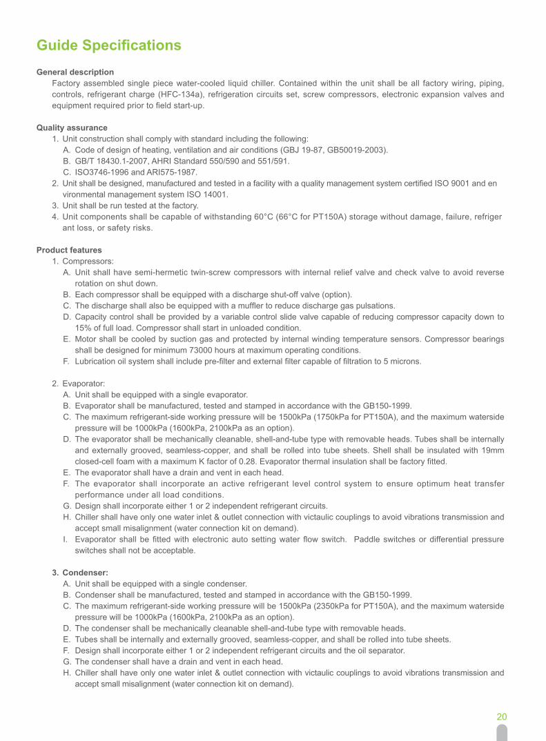
Guide SpecificationsGeneral description
Factory assembled single piece water-cooled liquid chiller. Contained within the unit shall be all factory wiring, piping, controls, refrigerant charge (HFC-134a), refrigeration circuits set, screw compressors, electronic expansion valves and equipment required prior to field start-up.
Quality assurance1. Unit construction shall comply with standard including the following:
A. Code of design of heating, ventilation and air conditions (GBJ 19-87, GB50019-2003).B. GB/T 18430.1-2007, AHRI Standard 550/590 and 551/591.C. ISO3746-1996 and ARI575-1987.
2. Unit shall be designed, manufactured and tested in a facility with a quality management system certified ISO 9001 and en vironmental management system ISO 14001.3. Unit shall be run tested at the factory.4. Unit components shall be capable of withstanding 60°C (66°C for PT150A) storage without damage, failure, refriger ant loss, or safety risks.
Product features1. Compressors:
A. Unit shall have semi-hermetic twin-screw compressors with internal relief valve and check valve to avoid reverse rotation on shut down.
B. Each compressor shall be equipped with a discharge shut-off valve (option).C. The discharge shall also be equipped with a muffler to reduce discharge gas pulsations.D. Capacity control shall be provided by a variable control slide valve capable of reducing compressor capacity down to
15% of full load. Compressor shall start in unloaded condition. E. Motor shall be cooled by suction gas and protected by internal winding temperature sensors. Compressor bearings
shall be designed for minimum 73000 hours at maximum operating conditions.F. Lubrication oil system shall include pre-filter and external filter capable of filtration to 5 microns.
2. Evaporator: A. Unit shall be equipped with a single evaporator.B. Evaporator shall be manufactured, tested and stamped in accordance with the GB150-1999. C. The maximum refrigerant-side working pressure will be 1500kPa (1750kPa for PT150A), and the maximum waterside
pressure will be 1000kPa (1600kPa, 2100kPa as an option). D. The evaporator shall be mechanically cleanable, shell-and-tube type with removable heads. Tubes shall be internally
and externally grooved, seamless-copper, and shall be rolled into tube sheets. Shell shall be insulated with 19mm closed-cell foam with a maximum K factor of 0.28. Evaporator thermal insulation shall be factory fitted.
E. The evaporator shall have a drain and vent in each head.F. The evaporator shall incorporate an active refrigerant level control system to ensure optimum heat transfer
performance under all load conditions.G. Design shall incorporate either 1 or 2 independent refrigerant circuits. H. Chiller shall have only one water inlet & outlet connection with victaulic couplings to avoid vibrations transmission and
accept small misalignment (water connection kit on demand).I. Evaporator shall be fitted with electronic auto setting water flow switch. Paddle switches or differential pressure
switches shall not be acceptable.
3. Condenser: A. Unit shall be equipped with a single condenser.B. Condenser shall be manufactured, tested and stamped in accordance with the GB150-1999. C. The maximum refrigerant-side working pressure will be 1500kPa (2350kPa for PT150A), and the maximum waterside
pressure will be 1000kPa (1600kPa, 2100kPa as an option).D. The condenser shall be mechanically cleanable shell-and-tube type with removable heads.E. Tubes shall be internally and externally grooved, seamless-copper, and shall be rolled into tube sheets. F. Design shall incorporate either 1 or 2 independent refrigerant circuits and the oil separator.G. The condenser shall have a drain and vent in each head.H. Chiller shall have only one water inlet & outlet connection with victaulic couplings to avoid vibrations transmission and
accept small misalignment (water connection kit on demand).
21
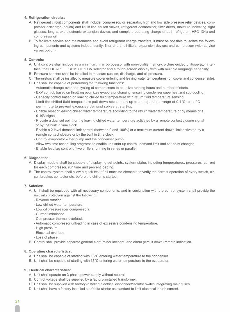
4. Refrigeration circuits:A. Refrigerant circuit components shall include, compressor, oil separator, high and low side pressure relief devices, com-
pressor discharge (option) and liquid line shutoff valves, refrigerant economizer, filter driers, moisture indicating sight glasses, long stroke electronic expansion device, and complete operating charge of both refrigerant HFC-134a and compressor oil.
B. To facilitate service and maintenance and avoid refrigerant charge transfers, it must be possible to isolate the follow-ing components and systems independently: filter driers, oil filters, expansion devices and compressor (with service valves option).
5. Controls: A. Unit controls shall include as a minimum: microprocessor with non-volatile memory, picture guided unit/operator inter-
face, the LOCAL/OFF/REMOTE/CCN selector and a touch-screen display with with multiple language capability.B. Pressure sensors shall be installed to measure suction, discharge, and oil pressure.C. Thermistors shall be installed to measure cooler entering and leaving water temperatures (on cooler and condenser side).D. Unit shall be capable of performing the following functions: - Automatic change-over and cycling of compressors to equalize running hours and number of starts. - EXV control, based on throttling optimizes evaporator charging, ensuring condenser superheat and sub-cooling. - Capacity control based on leaving chilled fluid temperature with return fluid temperature sensing. - Limit the chilled fluid temperature pull-down rate at start-up to an adjustable range of 0.1°C to 1.1°C per minute to prevent excessive demand spikes at start-up. - Enable reset of leaving chilled water temperature according to the return water temperature or by means of a 0-10V signal. - Provide a dual set point for the leaving chilled water temperature activated by a remote contact closure signal or by the built in time clock. - Enable a 2-level demand limit control (between 0 and 100%) or a maximum current drawn limit activated by a remote contact closure or by the built in time clock. - Control evaporator water pump and the condenser pump. - Allow two time scheduling programs to enable unit start-up control, demand limit and set-point changes. - Enable lead lag control of two chillers running in series or parallel.
6. Diagnostics: A. Display module shall be capable of displaying set points, system status including temperatures, pressures, current
for each compressor, run time and percent loading.B. The control system shall allow a quick test of all machine elements to verify the correct operation of every switch, cir-
cuit breaker, contactor etc. before the chiller is started.
7. Safeties: A. Unit shall be equipped with all necessary components, and in conjunction with the control system shall provide the
unit with protection against the following: - Reverse rotation. - Low chilled water temperature. - Low oil pressure (per compressor). - Current imbalance. - Compressor thermal overload. - Automatic compressor unloading in case of excessive condensing temperature. - High pressure. - Electrical overload. - Loss of phase.B. Control shall provide separate general alert (minor incident) and alarm (circuit down) remote indication.
8. Operating characteristics: A. Unit shall be capable of starting with 13°C entering water temperature to the condenser.B. Unit shall be capable of starting with 35°C entering water temperature to the evaoprator.
9. Electrical characteristics: A. Unit shall operate on 3-phase power supply without neutral. B. Control voltage shall be supplied by a factory-installed transformer.C. Unit shall be supplied with factory-installed electrical disconnect/isolator switch integrating main fuses.D. Unit shall have a factory installed star/delta starter as standard to limit electrical inrush current.

CAT_30XW_E-1911_13
CAT_30XW_E-1709_12
Oct, 2019
Version:
Supersede:
Effective date:
The Manufacturer reserves the right to change any produt specifications without prior notices


