BEFORE YOU BEGIN Read these instructions completely and carefully. • IMPORTANT — Save these instructions for local inspector’s use. • IMPORTANT — Observe all gov- erning codes and ordinances. • Note to Installer – Be sure to leave these instructions with Consumer. • Note to Consumer – Keep these instruc- tions for future reference. • Skill level – Installation of this appliance requires basic mechanical skills and advanced electrical skills. • Proper installation is the responsibility of the installer. • Product failure due to improper installation is not covered under Warranty. Installation Instructions 30" Electric Slide-In Ranges FOR YOUR SAFETY: If you did not receive an anti-tip bracket with your purchase, call 1.800.626.8774 to receive one at no cost. (In Canada, call 1.800.561.3344.) For installation instructions of the bracket, visit: www.geappliances.com. (In Canada, www.geappliances.ca.) Anti-Tip Bracket Kit Included Questions? Call 1.800.GE.CARES (1.800.432.2737) or visit www.geappliances.com In Canada, call 1.800.561.3344 or visit www.geappliances.ca WARNING — Before beginning the installation, switch power off at service panel and lock the service disconnecting means to prevent power from being switched on accidentally. When the service disconnecting means cannot be locked, secure- ly fasten a prominent warning device, such as a tag, to the service panel. MATERIALS YOU MAY NEED TOOLS YOU WILL NEED (UL Listed 40 AMP) 4-Wire Cord 4' long OR 3-Wire Cord 4' long Squeeze Connector (For Conduit Installations Only) REMOVE PACKAGING MATERIALS: Failure to remove packaging materials could result in damage to the appliance. Remove all packing parts from oven, racks, heating elements and drawer. Also, remove protective film and labels on the door, cooktop (do not remove side protection on glass cooktops) and backguard. Do not remove protective channel from sides of glass cooktop, if applicable, until later in installation. 1 Drill with 1/8" Bit Safety Glasses Adjustable Wrench Level Tin Snips Tape Measure Pliers 1/4" Nut Driver PREPARE THE OPENING (FOR INDOOR USE ONLY) If the countertop area is not flat, excess tension may be applied to the glass cooktop causing breakage and voiding the warranty. Make sure the wall covering, countertop, flooring and cabinets around the range can withstand the heat (up to 200˚F) generated by the range. A. Allow 30" minimum clearance between surface units and bottom of unprotected wood or metal cabinet, or allow a 24" minimum when bottom of wood or metal cabinet is protected by no less then 1/4" thick flame retardant millboard covered with no less than No. 28 MSG sheet metal (.015" thick), .015" thick stainless steel, .025" aluminum or .020" copper. B. This appliance has been approved for 0" spacing to adjacent surfaces above the cooktop. However, a minimum 6" spacing to surfaces less than 15" above the cooktop and adjacent cabinetry is recommended to reduce exposure to steam, grease splatter and heat. Allow 1/4" minimum clearance at the back wall. To reduce the risk of burns or fire when reaching over hot surface elements, cabinet storage space above the cooktop should be avoided. If cabinet storage space is to be provided above the cooktop, the risk can be reduced by installing a range hood that projects at least 5" beyond the front of the cabinets. Cabinets installed above the cooktop must be no deeper than 13". 2 31-1/4" 2-7/8" To front surface of countertop 25-3/4" (excluding handle) Height from floor to range top 35-7/8"–36-1/2" OR 36-1/2"–38" with lower trim slide-in kit (see Step 3) Acceptable electrical outlet area. Orient electrical receptacle so the length is parallel to floor. 46-3/8" 36-1/4" 7-1/2" 20-5/8" Door clearance from front surface of countertop 24" 30" Min. 9/16" 15" Min. 7-1/2" 2-1/2" 23-3/16" Acceptable electrical outlet area 25" 29-15/16"–30-1/16" For Profile models only, if countertop has a raised edge, shave raised edge to clear 31-1/8" wide control panel. 1/4" Min. Flat 35-7/8"–38" from Floor to countertop 2-1/2" B A 1-1/4" Min, from countertop to top of cabinet drawer. 4" 4" NOTE: Use a 4' power cord to prevent interference with the storage drawer. Power cords 4-1/2' to 6' long may have to be dressed to allow for proper draw- er closing.
Transcript
BEFORE YOU BEGINRead these instructions completely andcarefully.
• IMPORTANT — Save theseinstructions for local inspector’s use.
• IMPORTANT — Observe all gov-erning codes and ordinances.
• Note to Installer – Be sure to leave theseinstructions with Consumer.
• Note to Consumer – Keep these instruc-tions for future reference.
• Skill level – Installation of this appliancerequires basic mechanical skills and advanced electrical skills.
• Proper installation is the responsibility of the installer.
• Product failure due to improper installation is not covered under Warranty.
Installation Instructions
30" Electric Slide-In Ranges
FOR YOUR SAFETY:
If you did not receive an anti-tip bracket with your purchase, call 1.800.626.8774 to receive one at no cost. (In Canada, call 1.800.561.3344.) For installation instructions of the bracket, visit: www.geappliances.com. (In Canada, www.geappliances.ca.)
Anti-Tip Bracket
Kit Included
Questions? Call 1.800.GE.CARES (1.800.432.2737) or visit www.geappliances.com
In Canada, call 1.800.561.3344 or visit www.geappliances.ca
WARNING — Beforebeginning the installation, switchpower off at service panel andlock the service disconnectingmeans to prevent power frombeing switched on accidentally.When the service disconnectingmeans cannot be locked, secure-ly fasten a prominent warningdevice, such as a tag, to the service panel.
MATERIALS YOU MAY NEED TOOLS YOU WILL NEED
(UL Listed 40 AMP) 4-Wire Cord 4' long OR
3-Wire Cord 4' long
Squeeze Connector (For Conduit
Installations Only)
REMOVE PACKAGING MATERIALS: Failure to remove packagingmaterials could result in damage to the appliance. Remove all packing parts from oven,racks, heating elements and drawer. Also, remove protective film and labels on the door,cooktop (do not remove side protection on glass cooktops) and backguard.Do not remove protective channel from sides of glass cooktop, if applicable, until later in installation.
1
Drill with 1/8" Bit
Safety Glasses
Adjustable Wrench
Level
Tin Snips
Tape Measure
Pliers
1/4" Nut Driver
PREPARE THE OPENING (FOR INDOOR USE ONLY)
If the countertop area is not flat, excess tension may be applied to the glass cooktop causing breakage and voiding the warranty. Make sure the wall covering, countertop, flooring and cabinets around the rangecan withstand the heat (up to 200˚F) generated by the range.
A. Allow 30" minimum clearance between surface units and bottom of unprotected wood or metal cabinet, or allow a 24" minimum when bottom of wood or metal cabinet is protected by no less then 1/4" thickflame retardant millboard covered with no less than No. 28 MSG sheet metal (.015" thick), .015" thickstainless steel, .025" aluminum or .020" copper.
B. This appliance has been approved for 0" spacing to adjacent surfaces above the cooktop. However, a minimum 6" spacing to surfaces less than 15" above the cooktop and adjacent cabinetry is recommended to reduce exposure to steam, grease splatter and heat. Allow 1/4" minimum clearance at the back wall.
To reduce the risk of burns or fire when reaching over hot surface elements, cabinet storage space abovethe cooktop should be avoided. If cabinet storage space is to be provided above the cooktop, the risk can be reduced by installing a range hood that projects at least 5" beyond the front of the cabinets. Cabinetsinstalled above the cooktop must be no deeper than 13".
2
31-1/4"2-7/8" To front
surface ofcountertop
25-3/4" (excluding
handle)
Height from floor to range top35-7/8"–36-1/2"
OR36-1/2"–38" with lower trim
slide-in kit (see Step 3)
Acceptable electrical outlet area.Orient electrical receptacle so the length is parallel to floor.
46-3/8"
36-1/4" 7-1/2"
20-5/8" Door clearance from
front surface ofcountertop
24"
30" Min.
9/16"
15" Min.
7-1/2"
2-1/2"
23-3/16"
Acceptable electrical outlet area
25"
29-15/16"–30-1/16"
For Profile models only, ifcountertop has a raised edge,shave raised edge to clear 31-1/8" wide control panel.
1/4" Min. Flat
35-7/8"–38" fromFloor to countertop
2-1/2"
B
A
1-1/4" Min, from countertopto top of cabinet drawer.
4"
4"
NOTE: Use a 4' power cord to preventinterference with the storage drawer.Power cords 4-1/2' to 6' long may haveto be dressed to allow for proper draw-er closing.
DOOR REMOVAL (optional)Door removal is not a requirement for installation of the product
but is an added convenience. To remove the door:
A. Open the oven door as far as it will go.
B. Push both hinge locks down toward the door frame to the unlocked posi-
tion. This may require a flat-blade screwdriver.
DO NOT LIFT THE DOOR BY THE HANDLE!
C. Place hands on both sides of the door, and close the oven door
to the removal position. (Approximately 1"-2" from the closed position.)
D. Lift door up and out until the hinge arms clear the slots.
NOTE: The oven door is very heavy. Be sure you have a firm grip before lift-
ing the oven door off the hinges. Use caution once the door is removed.
Do not lay the door on its handle. This could cause dents or scratches.
Hingeunlockedposition
Hingeslot
Hingearm
Ratingplate
Ratingplate
PREPARE THE RANGE4Protective
channel
STORAGE DRAWER REMOVAL
A. Pull drawer out until it stops.
B. Lift front of drawer until the stops clear the guide.
C. Pull forward and remove the drawer.
Rail
Guide
StopStop
POWER CORD AND CONDUIT INSTALLA-
TION
A. Remove wire cover (on the back of range)
by removing screws using a 1/4" nut driver.
Do not discard these screws.
B. For power cord and 1" conduit only, remove the
knockout ring (13⁄8") located on bracket directly
below the terminal block. To remove the knockout,
use a pair of pliers to bend the knockout ring away
from the bracket and twist until ring is removed.
6
ELECTRICAL REQUIREMENTS
WARNING: This appliance must be properly grounded.
WARNING: All new constructions, mobile homes, recreational vehicles and installationswhere local codes do not allow grounding through neutral require a 4-conductor, UL-listed range cord.
WARNING: To prevent fire or shock, do not use an extension cord with this appliance.
WARNING: To prevent shock, remove house fuse or open circuit breaker before begin-ning installation.
We recommend you have the electrical wiring and hookup of your range connected by a qualifiedelectrician. After installation, have the electrician show you how to disconnect power from the range.
You must use a single-phase, 120/208 VAC or 120/240 VAC, 60 hertz electrical system. If youconnect to aluminum wiring, properly installed connectors approved for use with aluminum wiringmust be used.
Effective January 1, 1996, the National Electrical Code requires that new construction (not existing)utilize a 4-conductor connection to an electric range. When installing an electric range in new con-struction, mobile home, recreational vehicle, or an area where local codes prohibit groundingthrough the neutral conductor, refer to the section on four-conductor branch circuit connections.
Check with your local utilities for electrical codes which apply in your area. Failure to wire youroven according to governing codes could result in a hazardous condition. If there are no localcodes, your oven must be wired and fused to meet the National Electrical Code, NFPA No. 70 –latest edition, available from the National Fire Protection Association.
This appliance must be supplied with proper voltage and frequency and connected to an individ-ual, properly grounded, 40 amp (minimum) branch circuit protected by a circuit breaker or time-delay fuse.
Use only a 3-conductor or a 4-conductor UL-listed range cord. These cords may be provided with ring terminals on wire and a strain relief device.
A range cord rated at 40 amps with 125/250 minimum volt range is required. A 50 amp range cord is not recommended, but if used, it should be marked for use with nominal 13⁄8" diameter connection openings. Care should be taken to center the cable and strain relief within the knockout hole to keep the edge from damaging the cable.
The rating plate is located on the oven frame or on the side of the drawer frame.
5
Knockoutring inbracket
Knockout ringremoved
Terminal block(appearancemay vary)
ALTERNATE INSTALLATION / CONSTRUCTION KITS3Description:
Backguard Kit: Adds a decorative backguard to the rear of the range. This kit can only be used when the opening in the countertop is 25" deep.
Maintop Filler Kit: Adds a filler strip to the rear of the range.This kit can only be used when the opening in the countertopis 25" deep. This kit cannot be used with a backguard kit.
Body Side Kit: Contains a color-matched side panel whichcan be used to create a finished appearance on either side of the range.
Lower Trim Kit: Contains a color-matched toe kick and extra-long leveling legs. Designed to be used when the range needs to be raised higher than 36-1/2".
Use:
Designed to be used when replacinga free-standing range with a slide-in.
Used to fill gap between the rangeback and wall.
Designed to be used when cabinetsare absent on one side of the range.
Use kit when countertop height is36-1/2" to 38" high.
To order accessory kits, call 1.866.775.4557, or visit www.GEAppliances.com.
Hinge clears slot
Wirecover
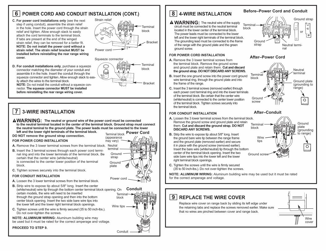
3-WIRE INSTALLATION
WARNING: The neutral or ground wire of the power cord must be connected to the neutral terminal located in the center of the terminal block. Ground strap must connectthe neutral teminal to the ground plate. The power leads must be connected to the lower left and the lower right terminals of the terminal block.
DO NOT remove the ground strap connection.
FOR POWER CORD INSTALLATION
A. Remove the 3 lower terminal screws from the terminal block.
B. Insert the 3 terminal screws through each power cord termi-nal ring and into the lower terminals of the terminal block. Becertain that the center wire (white/neutral) is connected to the center lower position of the terminalblock.
C. Tighten screws securely into the terminal block.
FOR CONDUIT INSTALLATION
A. Loosen the 3 lower terminal screws from the terminal block.
B. Strip wire to expose tip about 5/8" long. Insert the center (white/neutral) wire tip through the bottom center terminal block opening. Oncertain models, the wire will need to be inserted through the ground strap opening and then into the bottom center block opening. Insert the two side bare wire tips into the lower left and the lower right terminal block openings.
C. Tighten screws until the wire is firmly secured (35 to 50 inch-lbs.). Do not over-tighten the screws.
NOTE: ALUMINUM WIRING: Aluminum building wire may be used but it must be rated for the correct amperage and voltage.
PROCEED TO STEP 9.
7
Groundstrap
Terminal block(appearancemay vary)
Neutral terminal
Power cord
Ground plate
Power Cord
4-WIRE INSTALLATION
WARNING: The neutral wire of the supplycircuit must be connected to the neutral terminallocated in the lower center of the terminal block.The power leads must be connected to the lowerleft and the lower right terminals of the terminal block. The grounding lead must be connected to the frame of the range with the ground plate and the green ground screw.
FOR POWER CORD INSTALLATION
A. Remove the 3 lower terminal screws from the terminal block. Remove the ground screw and ground plate and retain them. Cut and discard the ground strap. DO NOT DISCARD ANY SCREWS.
B. Insert the one ground screw into the power cord groundwire terminal ring, through the ground plate and into the frame of the range.
C. Insert the 3 terminal screws (removed earlier) through each power cord terminal ring and into the lower terminals of the terminal block. Be certain that the center wire(white/neutral) is connected to the center lower position of the terminal block. Tighten screws securely into the terminal block.
FOR CONDUIT INSTALLATION
A. Loosen the 3 lower terminal screws from the terminal block.Remove the ground screw and ground plate and retainthem. Cut and discard the ground strap. DO NOTDISCARD ANY SCREWS.
B. Strip the wire to expose tip about 5/8" long. Insert the ground bare wire tip between the range frame and the ground plate (removed earlier) and secure it in place with the ground screw (removed earlier). Insert the bare wire (white/neutral) tip through the bottom center of the terminal block opening. Insert the two side bare wire tips into the lower left and the lower right terminal block openings.
C. Tighten the screws until the wire is firmly secured (35 to 50 inch-lbs.). Do not over-tighten the screws.
NOTE: ALUMINUM WIRING: Aluminum building wire may be used but it must be rated for the correct amperage and voltage.
8Before–Power Cord and Conduit
Terminalblock
Terminalblock
Neutral termi-nal
Neutralterminal
Groundstrap
Ground plate(grounding torange)
Groundscrew
Ground strap
or
After–Conduit
Terminalblock
Groundplate(groundingto range)
Wiretips
Ground screw
After–Power Cord
REPLACE THE WIRE COVERReplace wire cover on range back by sliding its left edge under
the retaining tabs and replace the screws removed earlier. Make sure
that no wires are pinched between cover and range back.
9
POWER CORD AND CONDUIT INSTALLATION (CONT.)
C. For power cord installations only (see the nextstep if using conduit), assemble the strain relief in the hole. Insert the power cord through the strainrelief and tighten. Allow enough slack to easilyattach the cord terminals to the terminal block. If tabs are present at the end of the winged strain relief, they can be removed for a better fit.NOTE: Do not install the power cord without astrain relief. The strain relief bracket MUST beinstalled before reinstalling the rear range wiringcover.
D. For conduit installations only, purchase a squeezeconnector matching the diameter of your conduit andassemble it in the hole. Insert the conduit through thesqueeze connector and tighten. Allow enough slack to eas-ily attach the wires to the terminal block.NOTE: Do not install the conduit without a squeeze con-nector. The squeeze connector MUST be installedbefore reinstalling the rear range wiring cover.
6
Power cord
Strain relief
Terminal
block
Bracket
Squeeze connector
Terminal
block
Bracket
Wirecover
Wire tips
Terminal block
Conduit
Conduit
REPLACING THE OVEN DOORNOTE: The oven door is heavy. You may need help lifting the door high enough
to slide it into the hinge slots. Do not lift the door by the handle.A. Lift the oven door by placing one hand on each side. The door is heavy,
so you may need help. Do not lift the door by the handle.
B. With the door at the same angle as the removal position (approximately
1"-2" from the closed position), seat the notch of the hinge arm into
the bottom edge of the hinge slot. The notch of the hinge arm must
be fully seated into the bottom of the slot.
C. Fully open the door. If the door will not fully open, the indentation
is not seated correctly in the bottom edge of the slot.
D. Push the hinge locks up against
the front frame of the oven cavity,
to the locked position.
E. Close the oven door.
12
REPLACE THE STORAGE DRAWER
A. Place the drawer rail on the guides. Push the drawer in until it stops.
B. Lift front of the drawer and push in until the stops clear the guides.
C. Lower the front of the drawer and push in until it closes.Stop
SLIDE RANGE INTO OPENING
A. Position the range in front of the cabinet opening. Make sure that
the glass that overhangs the countertop clears the countertop.
If necessary, raise the unit by lowering the leveling legs.
B. Push while lifting the range into the opening, until the range
is within 2" of engaging the anti-tip bracket. Remove the protective
trim from the side of glass (if provided).
C. Using the adjustable pliers or wrench, carefully screw
in the back leveling leg until the glass overhang comes
to rest on the countertop. Then carefully screw in
the front two leveling legs until the glass overhang
touches the countertop.
D. Carefully push the range into the opening until
the countertop fully engages the control panel.
The back glass overhang should cover the cutout
opening. Plug the range cord into the receptacle.
Locate the cord in the back of the range in a manner
that it will not touch or be moved by the drawer.
11
Position range cord so that there is nointerference with the storage drawer
STORAGE DRAWER
Hinge notch
Hinge in lockedposition
Notch of hingesecurely fittedinto bottom of hinge slot
Make sure edge of countertop fits flushagainst the end of Front Control Panel
Countertop
ANTI-TIP DEVICE INSTALLATIONTo reduce the risk of tipping the range, the range
must be secured by a properly installed anti-tip bracket.
See installation instructions shipped with the bracket
for complete details before attempting to install.
To check if the bracket is installed and engaged properly,
remove the storage drawer or kick panel and look under-
neath the range to see that the leveling leg
is engaged in the bracket. On models without a storage
drawer or kick panel, carefully tip the range forward.
The bracket should stop the range within 4 inches. If it does not, the bracket must be reinstalled.
If the range is pulled from the wall for any reason, always repeat this procedure to verify the range
is properly secured by the anti-tip bracket. Never completely remove the leveling legs or the range
will not be secured to the anti-tip device properly.
10
FINAL INSTALLATION CHECKLIST • Check to make sure the circuit breaker is closed (RESET) or the circuit fuses are replaced.
• Be sure power is in service to the building.
• Check that all packing materials and tape have been removed. This will include tape on metal panel
under control knobs (if applicable), adhesive tape, wire ties, cardboard and protective plastic. Failure
to remove these materials could result in damage to the appliance once the appliance has been
turned on and surfaces have heated.
• Check that the door and drawer are parallel to each other and that both operate smoothly.
If they do not, see the Owner’s Manual for proper replacement.
• Check to make sure that the rear leveling leg is fully inserted into the anti-tip bracket
and that the bracket is securely installed.
OPERATION CHECKLIST• Turn on one of the surface units to observe that the element glows within 60 seconds. Turn the unit
off when glow is detected. If the glow is not detected within the time limit, recheck the range wiring
connections. If change is required, retest again. If no change is required, have building wiring checked
for proper connections and voltage.
• Check that the oven control operates properly. If the oven control does not operate properly,
recheck the wiring connections.
• Be sure all range controls are in the OFF position before leaving the range.


![USTA TrafficAnalysisBriefing V7 0 20150530 FINAL[1] · PDF file1."Executive"Summary" ... In2014thethreemajorGulfcarriers" –"Emirates,"Qatar"Airways"and"Etihad" Airways"–"carried"some"4.3"million"passengers"intoandout"of"the](https://static.documents.pub/doc/80x56/5aa125967f8b9a46238b5bf2/usta-trafficanalysisbriefing-v7-0-20150530-final1-in2014thethreemajorgulfcarriers.jpg)
