Instructions – Parts List GRACO INC.ąP.O. BOX 1441ąMINNEAPOLIS, MNą55440-1441 Copyright 1996, Graco Inc. is registered to I.S. EN ISO 9001 CARBON STEEL 200 LITER (55 GALLON) AND 20 LITER (5 GALLON) Therm-O-Flow R Pump Modules (Heated Check-Mate800) with heaters, insulation, and shrouds 398 bar (5850 psi) Maximum Fluid Working Pressure 200 Liter (55 Gallon) 243276 TOF Plus Pump Module (all voltages) 241987 Pump Module, 480 VAC 20 Liter (5 Gallon) C03509 Pump Module, 480/575 VAC C03512 Pump Module, 240 VAC 310530H Read warnings and instructions. See page 2 for Table of Contents. Model C03509
Transcript
Instructions – Parts List
�������������� ������������������������������
����������� �����������������������������������
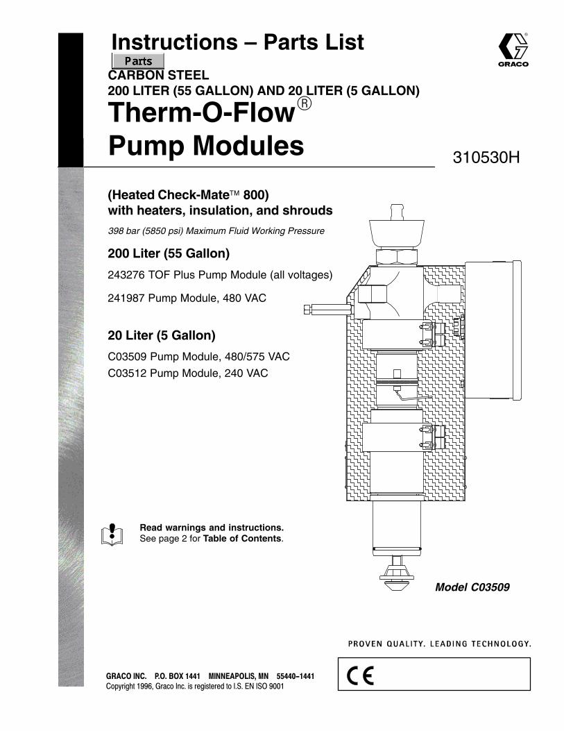
CARBON STEEL200 LITER (55 GALLON) AND 20 LITER (5 GALLON)
Therm-O-Flow�
Pump Modules
(Heated Check-Mate 800)with heaters, insulation, and shrouds
398 bar (5850 psi) Maximum Fluid Working Pressure
200 Liter (55 Gallon)
243276 TOF Plus Pump Module (all voltages)
241987 Pump Module, 480 VAC
20 Liter (5 Gallon)
C03509 Pump Module, 480/575 VAC
C03512 Pump Module, 240 VAC
310530H
Read warnings and instructions.See page 2 for Table of Contents.
Model C03509
2 310530
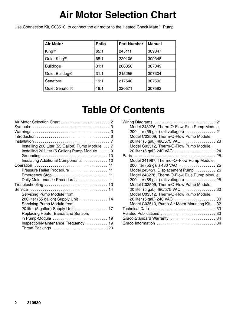
Air Motor Selection ChartUse Connection Kit, C03510, to connect the air motor to the Heated Check Mate� Pump.
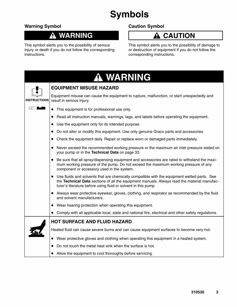
WARNINGThis symbol alerts you to the possibility of seriousinjury or death if you do not follow the correspondinginstructions.
Caution Symbol
CAUTIONThis symbol alerts you to the possibility of damage toor destruction of equipment if you do not follow thecorresponding instructions.
WARNING
INSTRUCTIONS
EQUIPMENT MISUSE HAZARD
Equipment misuse can cause the equipment to rupture, malfunction, or start unexpectedly andresult in serious injury.
� This equipment is for professional use only.
� Read all instruction manuals, warnings, tags, and labels before operating the equipment.
� Use the equipment only for its intended purpose.
� Do not alter or modify this equipment. Use only genuine Graco parts and accessories.
� Check the equipment daily. Repair or replace worn or damaged parts immediately.
� Never exceed the recommended working pressure or the maximum air inlet pressure stated onyour pump or in the Technical Data on page 33.
� Be sure that all spray/dispensing equipment and accessories are rated to withstand the maxi-mum working pressure of the pump. Do not exceed the maximum working pressure of anycomponent or accessory used in the system.
� Use fluids and solvents that are chemically compatible with the equipment wetted parts. Seethe Technical Data sections of all the equipment manuals. Always read the material manufac-turer’s literature before using fluid or solvent in this pump.
� Always wear protective eyewear, gloves, clothing, and respirator as recommended by the fluidand solvent manufacturers.
� Wear hearing protection when operating this equipment.
� Comply with all applicable local, state and national fire, electrical and other safety regulations.
HOT SURFACE AND FLUID HAZARD
Heated fluid can cause severe burns and can cause equipment surfaces to become very hot.
� Wear protective gloves and clothing when operating this equipment in a heated system.
� Do not touch the metal heat sink when the surface is hot.
� Allow the equipment to cool thoroughly before servicing.
4 310530
WARNINGINJECTION HAZARD
Spray from the spray gun, hose leaks, or ruptured components can inject fluid into your body andcause extremely serious injury, including the need for amputation. Splashing fluid in the eyes or onthe skin can also cause serious injury.
� Fluid injected into the skin might look like just a cut, but it is a serious injury. Get immediatemedical attention.
� Do not point the gun/valve at anyone or at any part of the body.
� Do not put your hand or fingers over the spray tip/nozzle.
� Do not stop or deflect fluid leaks with your hand, body, glove, or rag.
� Always have the trigger guard on the gun when dispensing.
� Check the gun diffuser operation weekly. Refer to the gun manual.� Check the gun diffuser o eration weekly. Refer to the gun manual.
� Be sure the gun/valve trigger safety operates before dispensing.
� Lock the gun/valve trigger safety when you stop dispensing.
� Follow the Pressure Relief Procedure on page 11 if the nozzle clogs, and before cleaning,checking or servicing the equipment.
� Tighten all fluid connections before operating the equipment.
� Check the hoses, tubes, and couplings daily. Replace worn, damaged, or loose parts immedi-ately. Do not repair high pressure couplings; you must replace the entire hose.
FIRE, EXPLOSION AND ELECTRIC SHOCK HAZARD
Improper grounding, poor air ventilation, open flames, or sparks can cause a hazardous conditionand result in fire, explosion, or electrostatic shock and other serious injury.
� Ground the equipment, the object being dispensed, and all other electrically conductive objectsin the dispense area. Proper grounding dissipates static electricity generated in the equipment.See Grounding on page 10.
� Do not use this equipment with flammable liquids.
� Keep the dispense area free of debris, including solvent, rags, and gasoline.
� If there is any static sparking while using the equipment, stop dispensing immediately. Identi-fy and correct the problem.
� Make sure all electrical work is performed by a qualified electrician only.
� Make sure all electrical equipment is installed and operated in compliance with applicablecodes.
� Make sure power is disconnected when servicing and repairing equipment.
� Have any checks, installation, or service to electrical equipment performed by a qualified electri-cian only.
5310530
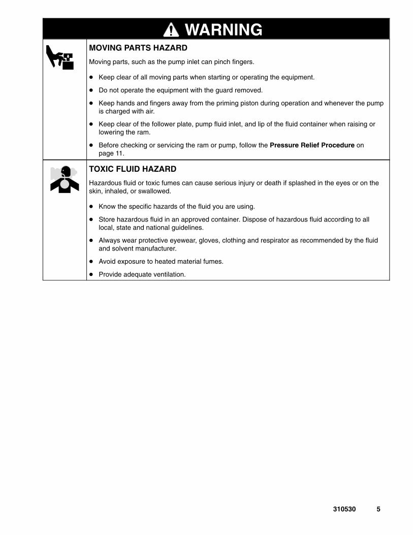
WARNINGMOVING PARTS HAZARD
Moving parts, such as the pump inlet can pinch fingers.
� Keep clear of all moving parts when starting or operating the equipment.
� Do not operate the equipment with the guard removed.
� Keep hands and fingers away from the priming piston during operation and whenever the pumpis charged with air.
� Keep clear of the follower plate, pump fluid inlet, and lip of the fluid container when raising orlowering the ram.
� Before checking or servicing the ram or pump, follow the Pressure Relief Procedure onpage 11.
TOXIC FLUID HAZARD
Hazardous fluid or toxic fumes can cause serious injury or death if splashed in the eyes or on theskin, inhaled, or swallowed.
� Know the specific hazards of the fluid you are using.
� Store hazardous fluid in an approved container. Dispose of hazardous fluid according to alllocal, state and national guidelines.
� Always wear protective eyewear, gloves, clothing and respirator as recommended by the fluidand solvent manufacturer.
� Avoid exposure to heated material fumes.
� Provide adequate ventilation.
6 310530
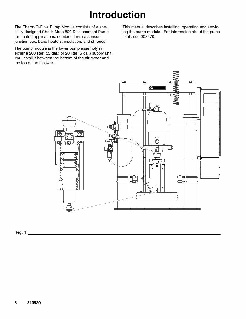
IntroductionThe Therm-O-Flow Pump Module consists of a spe-cially designed Check-Mate 800 Displacement Pumpfor heated applications, combined with a sensor,junction box, band heaters, insulation, and shrouds.
The pump module is the lower pump assembly ineither a 200 liter (55 gal.) or 20 liter (5 gal.) supply unit.You install it between the bottom of the air motor andthe top of the follower.
This manual describes installing, operating and servic-ing the pump module. For information about the pumpitself, see 308570.
� you have your system documentation and copies ofthe following manuals:
� 310523 (200 l/55 gal.) ram� 310527 (200 l/55 gal.) TOF supply unit or
309085 (200 l/55 gal.) TOF Plus supply unit� 308570 (servicing the pump)
� either the air motor is secured in the ram (if youused the procedure in 310527), or you have 2people to hold the pump assembly
To connect the pump module to the air motor, followthis procedure:
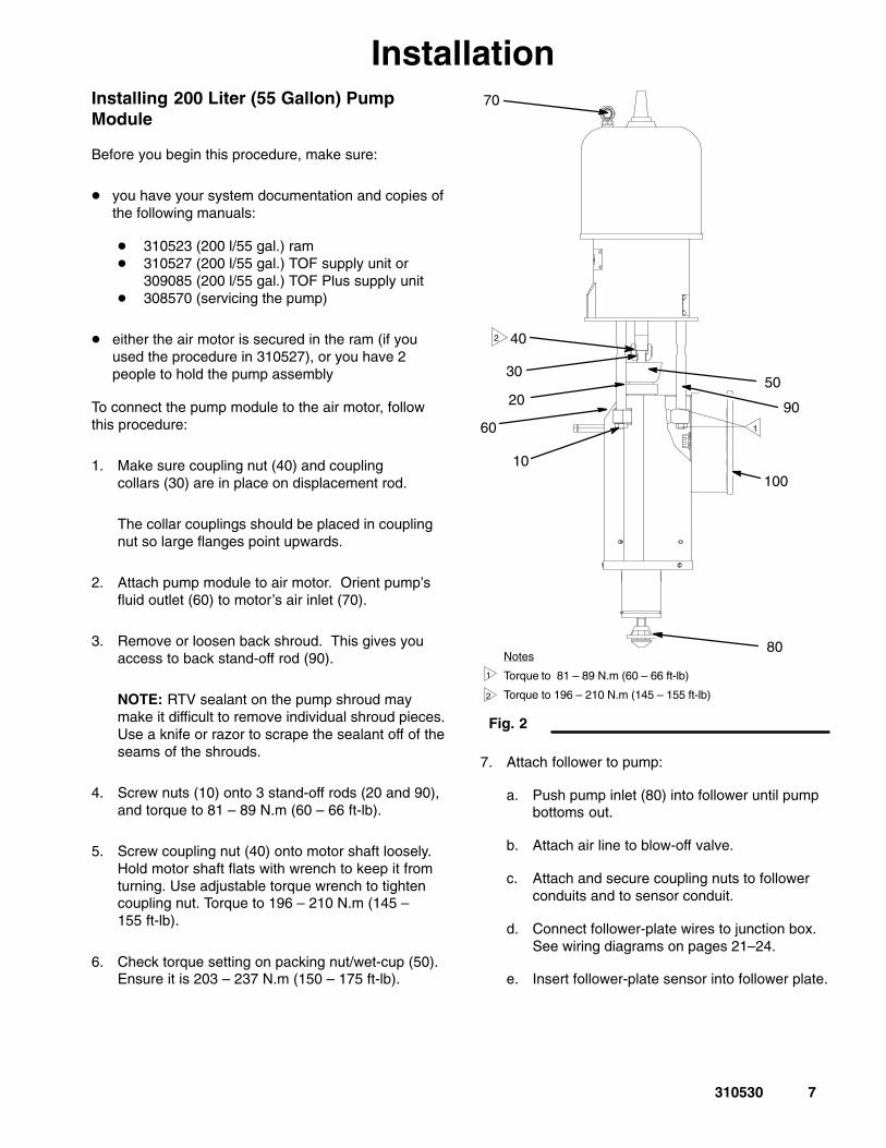
1. Make sure coupling nut (40) and couplingcollars (30) are in place on displacement rod.
The collar couplings should be placed in couplingnut so large flanges point upwards.
2. Attach pump module to air motor. Orient pump’sfluid outlet (60) to motor’s air inlet (70).
3. Remove or loosen back shroud. This gives youaccess to back stand-off rod (90).
NOTE: RTV sealant on the pump shroud maymake it difficult to remove individual shroud pieces.Use a knife or razor to scrape the sealant off of theseams of the shrouds.
5. Screw coupling nut (40) onto motor shaft loosely.Hold motor shaft flats with wrench to keep it fromturning. Use adjustable torque wrench to tightencoupling nut. Torque to 196 – 210 N.m (145 –155 ft-lb).
6. Check torque setting on packing nut/wet-cup (50).Ensure it is 203 – 237 N.m (150 – 175 ft-lb).
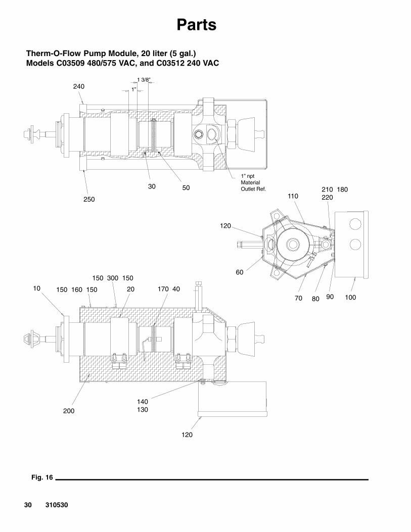
Fig. 2
10
20
30
40
1
2
Notes
Torque to 81 – 89 N.m (60 – 66 ft-lb)
Torque to 196 – 210 N.m (145 – 155 ft-lb)
1
2
50
70
60
80
90
100
7. Attach follower to pump:
a. Push pump inlet (80) into follower until pumpbottoms out.
b. Attach air line to blow-off valve.
c. Attach and secure coupling nuts to followerconduits and to sensor conduit.
d. Connect follower-plate wires to junction box.See wiring diagrams on pages 21–24.
e. Insert follower-plate sensor into follower plate.
8. When re-installing pump module, wire pump tojunction box (100). If pump module is alreadywired to junction box, go to step 9.
a. Open cover of junction box.
b. Connect pump’s heater wires and sensor wireto correct terminals in junction box. See wiringdiagrams in Fig. 14 (480/575 VAC) or Fig. 15(240 VAC).
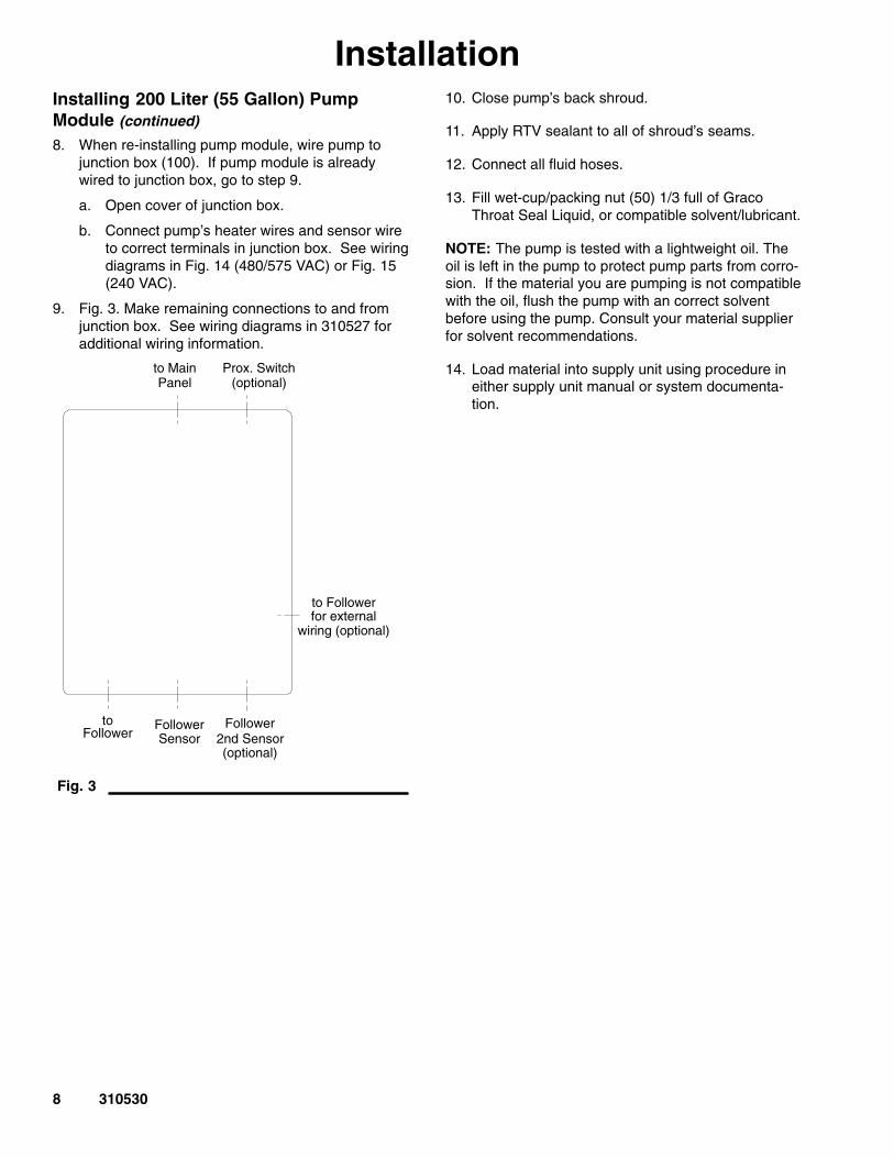
9. Fig. 3. Make remaining connections to and fromjunction box. See wiring diagrams in 310527 foradditional wiring information.
Fig. 3
to Main Prox. Switch(optional)Panel
to Followerfor external
Follower2nd Sensor(optional)
FollowerSensor
to
wiring (optional)
Follower
10. Close pump’s back shroud.
11. Apply RTV sealant to all of shroud’s seams.
12. Connect all fluid hoses.
13. Fill wet-cup/packing nut (50) 1/3 full of GracoThroat Seal Liquid, or compatible solvent/lubricant.
NOTE: The pump is tested with a lightweight oil. Theoil is left in the pump to protect pump parts from corro-sion. If the material you are pumping is not compatiblewith the oil, flush the pump with an correct solventbefore using the pump. Consult your material supplierfor solvent recommendations.
14. Load material into supply unit using procedure ineither supply unit manual or system documenta-tion.
� air motor is secured in the ram (if procedure in310528 was used), or 2 people are available to holdpump assembly
Connect pump module to air motor as follows:
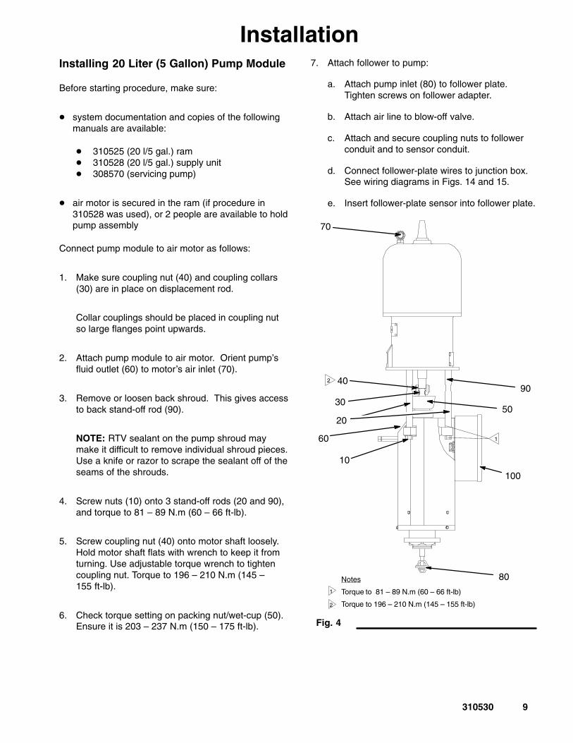
1. Make sure coupling nut (40) and coupling collars(30) are in place on displacement rod.
Collar couplings should be placed in coupling nutso large flanges point upwards.
2. Attach pump module to air motor. Orient pump’sfluid outlet (60) to motor’s air inlet (70).
3. Remove or loosen back shroud. This gives accessto back stand-off rod (90).
NOTE: RTV sealant on the pump shroud maymake it difficult to remove individual shroud pieces.Use a knife or razor to scrape the sealant off of theseams of the shrouds.
5. Screw coupling nut (40) onto motor shaft loosely.Hold motor shaft flats with wrench to keep it fromturning. Use adjustable torque wrench to tightencoupling nut. Torque to 196 – 210 N.m (145 –155 ft-lb).
6. Check torque setting on packing nut/wet-cup (50).Ensure it is 203 – 237 N.m (150 – 175 ft-lb).
7. Attach follower to pump:
a. Attach pump inlet (80) to follower plate.Tighten screws on follower adapter.
b. Attach air line to blow-off valve.
c. Attach and secure coupling nuts to followerconduit and to sensor conduit.
d. Connect follower-plate wires to junction box.See wiring diagrams in Figs. 14 and 15.
e. Insert follower-plate sensor into follower plate.
8. When re-installing pump module, wire pump tojunction box (100). If pump module is alreadywired to junction box, go to step 9.
a. Open cover of junction box.
b. Connect pump’s heater wires and sensor wireto correct terminals in junction box. See wiringdiagrams in Fig.14 (480/575 VAC) or Fig. 15(240 VAC).
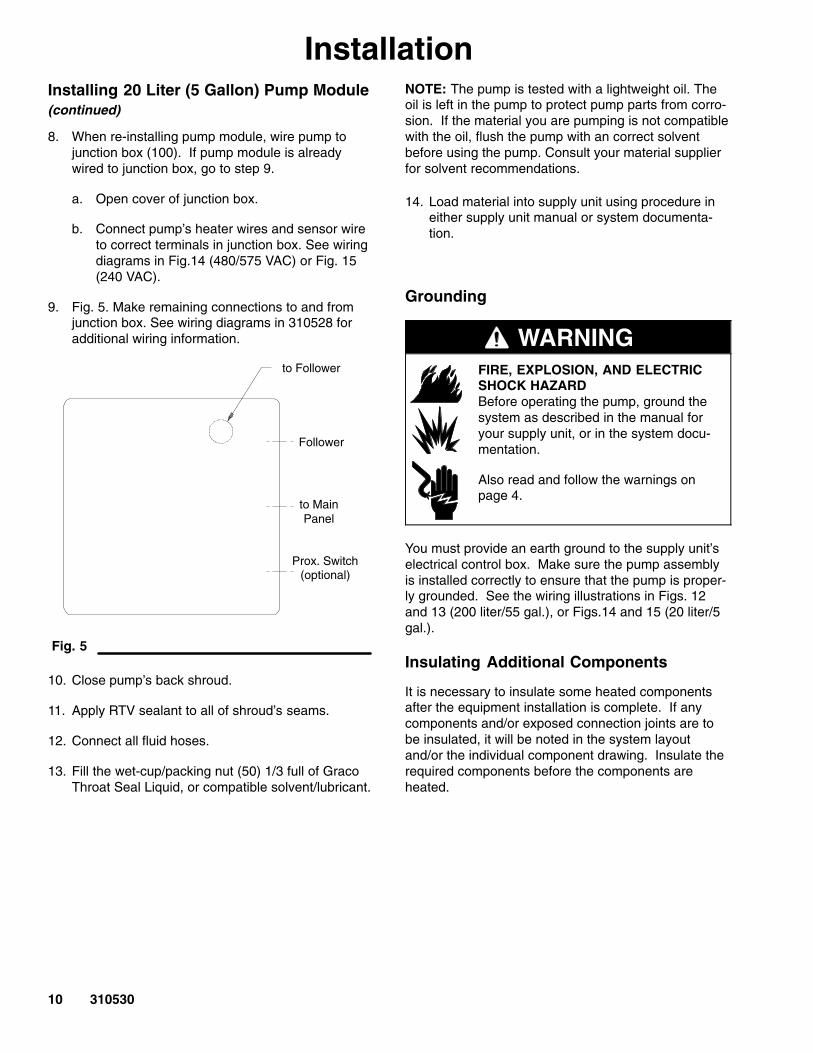
9. Fig. 5. Make remaining connections to and fromjunction box. See wiring diagrams in 310528 foradditional wiring information.
Fig. 5
to Follower
Follower
to Main
Prox. Switch(optional)
Panel
10. Close pump’s back shroud.
11. Apply RTV sealant to all of shroud’s seams.
12. Connect all fluid hoses.
13. Fill the wet-cup/packing nut (50) 1/3 full of GracoThroat Seal Liquid, or compatible solvent/lubricant.
NOTE: The pump is tested with a lightweight oil. Theoil is left in the pump to protect pump parts from corro-sion. If the material you are pumping is not compatiblewith the oil, flush the pump with an correct solventbefore using the pump. Consult your material supplierfor solvent recommendations.
14. Load material into supply unit using procedure ineither supply unit manual or system documenta-tion.
Grounding
WARNINGFIRE, EXPLOSION, AND ELECTRICSHOCK HAZARDBefore operating the pump, ground thesystem as described in the manual foryour supply unit, or in the system docu-mentation.
Also read and follow the warnings onpage 4.
You must provide an earth ground to the supply unit’selectrical control box. Make sure the pump assemblyis installed correctly to ensure that the pump is proper-ly grounded. See the wiring illustrations in Figs. 12and 13 (200 liter/55 gal.), or Figs.14 and 15 (20 liter/5gal.).
Insulating Additional Components
It is necessary to insulate some heated componentsafter the equipment installation is complete. If anycomponents and/or exposed connection joints are tobe insulated, it will be noted in the system layoutand/or the individual component drawing. Insulate therequired components before the components areheated.
11310530
OperationPressure Relief Procedure
WARNINGINJECTION HAZARDThe system pressure must be manuallyrelieved to prevent the system fromstarting or spraying accidentally. Fluid
under high pressure can be injected through theskin and cause serious injury. To reduce the risk ofan injury from injection, splashing fluid, or movingparts, follow the Pressure Relief Procedurewhenever you:
� are instructed to relieve the pressure
� stop spraying/dispensing
� check or service any of the system equipment
� install or clean the spray tip/nozzle
Use this procedure whenever you shut off the dispens-er/sprayer and before checking or adjusting any part ofthe system, to reduce the risk of serious injury.
1. Lock the gun/valve trigger safety.
2. Shut off the main air supply to the pump.
3. Close all air bleed valves.
4. Unlock the gun/valve trigger safety.
5. Hold a metal part of the gun/valve firmly to the sideof a grounded metal drum or pail, and trigger thegun/valve to relieve pressure.
6. Lock the gun/valve trigger safety.
7. Have a container ready to catch the drainage, thenopen the drain valve or pump bleed valve.
8. Leave the drain valve open until you are ready tospray/dispense again.
If you suspect that the spray tip/nozzle or hose iscompletely clogged, or that pressure has not been fullyrelieved after following the steps above, very slowlyloosen the tip guard retaining nut or hose end couplingto relieve pressure gradually, then loosen completely.Now clear the tip/nozzle or hose.
9. To relieve pressure in the ram, see Ram PressureRelief Procedure in the supply unit’s documenta-tion.
Emergency Stop
See instructions in either supply unit or system docu-mentation for more information.
1. On supply unit’s electrical control panel:
a. Turn CONTROL ON switch to OFF.
b. Turn OFF main electrical disconnect.
2. Stop pump by closing Bleed-type Master Air Valveclosest to motor’s air inlet.
Daily Maintenance Procedures
WARNINGUse fluids and solvents that are chemically compat-ible with the equipment wetted parts. See theTechnical Data sections of all the equipmentmanuals. Always read the material manufacturer’sliterature before using fluid or solvent in this pump.
1. Clean out material build-up in wet-cup to extendlife of pump packing and displacement rod.
2. Ensure packing nut/wet-cup is tightened to correcttorque setting, 203 – 237 N.m (150 – 175 ft-lb).Do not overtighten packing nut.
3. Before starting pump, fill wet-cup 1/3 full withGraco Throat Seal Liquid or compatible solvent.
NOTE: Adding Graco Throat Seal Liquid or othercompatible solvents to wet-cup will help lubricatethe seal and prevent material leakage.
For additional maintenance procedures, see the Op-eration/Maintenance section of 308570.
12 310530
OperationFlushing Safety
WARNINGUse fluids and solvents that are chemically compat-ible with the equipment wetted parts. See theTechnical Data sections of all the equipmentmanuals. Always read the material manufacturer’sliterature before using fluid or solvent in this pump.
Before flushing:
1. Ensure entire system and flushing drums or pailsare properly grounded. See system manual orsupply unit manual for more information.
WARNINGTo reduce the risk of serious injury, whenever youare instructed to relieve pressure always follow thePressure Relief Procedure on page 11.
2. Perform the Pressure Relief Procedure onpage 11.
PRESSURIZED FLUID HAZARDAlways use the lowest possible fluidpressure, and maintain firm metal-to-metal contact between the gun/valve
and the drum or pail during flushing to reduce therisk of fluid injection injury, static sparking andsplashing.
WARNING
3. Remove spray tip/nozzle from spray gun/dispens-ing valve.
13310530
TroubleshootingFor additional trouble-shooting information about the pump, see the pump’s documentation.
Problem Cause(s) Solution(s)
Rapid down stroke or up stroke Material not heated to properpumping temperature
Check and adjust temperature set point.
Air is trapped in pump Bleed air from the pump using this pro-cedure:
1. Place a waste container under thepump bleed port.
2. Turn on air to the pump
3. Allow material to flow from the bleedport until it is air-free.
4. Shut off air to the pump and closethe bleed port.
5. Turn air on to the pump and set thepump air regulator for normal opera-tion.
Downstroke: Lower check inpump is worn
Upstroke: Upper check in pump isworn
Rebuild and replace pump, as neces-sary.
Material leaks around pump outlet Outlet fitting is loose Tighten outlet fitting.
Material leaks around bleed port Bleed port fitting is loose Tighten bleed port fitting.
Pump won’t move up or down Problem with air motor See Air Motor Troubleshooting chart insupply unit or system documentation.
Foreign object lodged in pump Remove object and rebuild pumpassembly. See 308570 for pumprebuild instructions.
WARNINGTo reduce the risk of serious injurywhenever you are instructed to relievepressure, always follow the PressureRelief Procedure on page 11.
Before attempting to dislodge a foreignobject:
1. Relieve system pressure.
2. Remove the pump from the airmotor.
Pump fails to prime properly Pump needs to be primed See Use of the Bleeder Valve in308570.
Wet-cup leaks Throat seal is worn Replace throat seal. See Servicing theThroat Packings in 308570
14 310530
ServiceThis section contains the procedures for:
� servicing a pump module from a 200 liter (55 gal-lon) supply unit
� servicing a pump module from a 20 liter (5 gallon)supply unit
� replacing the sensor and heater bands in the pump-module
For information about servicing the pump unit itself,see 308570.
Servicing Pump Module from 200 liter (55gallon) Supply Unit
This section describes how to:
� remove a pump module from a supply unit (200liter/55 gal. or 20 liter/5 gal.)
� separate the pump module from the air motor(including disassembling the pump module)
� replace a pump module in a supply unit (200 liter/55 gal. or 20 liter/5 gal.)
Removing Pump Module from 200 Liter (55 gallon)Supply Unit
To remove the pump assembly from the ram, followthis procedure:
1. Remove the material drum from the supply unit:
WARNINGThe material and equipment will behot! To reduce risk of injury, wear eyeprotection, gloves and protective clothingwhen installing, operating, or servicingthis dispensing system.
a. Raise the ram out of the drum using the ramhand valve. At the same time, carefully equal-ize the pressure in the drum by cycling thefollower blow-off valve open and closed.
b. With the follower completely out of the drum,remove the drum.
c. Being careful not to damage the followerwipers, wipe any material build-up from thefollower plate and wipers.
d. Move the ram hand valve to the OFF position.
2. Make sure the ram hand valve is in the OFFposition.
3. Relieve the supply unit pressure.
WARNINGTo reduce the risk of serious injury whenever youare instructed to relieve pressure, always follow thePressure Relief Procedure on page 11.
4. Relieve the ram air pressure.
WARNINGTo reduce the risk of serious injury whenever youare instructed to relieve ram pressure, alwaysfollow the Ram Pressure Relief Procedure in thesupply unit or system documentation.
5. Turn the system CONTROL ON switch (located onthe supply unit’s electrical control panel) to OFF.
WARNINGELECTROCUTION HAZARD
To reduce risk of injury or damage toequipment, make sure the main discon-nect is OFF before continuing with thisprocedure.
6. Turn OFF the main electrical disconnect.
7. Turn off the electrical power to the supply unit.Follow all applicable safety procedures and lockoutrules.
8. Bleed off pressure in the system and excessmaterial by opening the dispense gun and catchingthe material in a waste container.
9. Disconnect all material hoses.
Fig. 7
5
4
6
3
15310530
ServiceRemoving the Pump Module from 200 Liter(55 gallon) Supply Unit (continued)
1. RTV sealant on the pump shrouds (1) may make itdifficult to remove individual shroud pieces. Usinga knife or razor, scrape the sealant off of theseams of the shrouds.
Fig. 6
2
1
2. Fig. 6 and Fig.14 for 480/575 VAC, Fig. 15 for240 VAC. Disconnect the junction box from thepump module by:
a. Removing the cover of the junction box (2).
b. Disconnecting the sensor wire and heaterwires that come from the pump.
c. Removing the wires from the junction box.
d. Disconnecting the pump’s back shroud andmoving it backwards out of the way.
3. Fig. 7. Loosen the pump mounting screws (5) and then remove the pump mounting plates (4).
4. Secure the air motor to the ram tie bar (3).
5. Leaving the air motor attached to the tie bar, sepa-rate the pump module (6) from the air motor. Goto the Separating the 200 Liter (55 Gallon)Pump Module from the Air Motor section.
16 310530
Service
Fig. 8
10
20
30
40
1
2
50
70
60
80
90
100
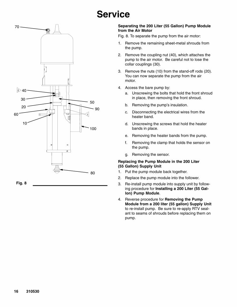
Separating the 200 Liter (55 Gallon) Pump Modulefrom the Air MotorFig. 8. To separate the pump from the air motor:
1. Remove the remaining sheet-metal shrouds fromthe pump.
2. Remove the coupling nut (40), which attaches thepump to the air motor. Be careful not to lose thecollar couplings (30).
3. Remove the nuts (10) from the stand-off rods (20).You can now separate the pump from the airmotor.
4. Access the bare pump by:a. Unscrewing the bolts that hold the front shroud
in place, then removing the front shroud.
b. Removing the pump’s insulation.
c. Disconnecting the electrical wires from theheater band.
d. Unscrewing the screws that hold the heaterbands in place.
e. Removing the heater bands from the pump.
f. Removing the clamp that holds the sensor onthe pump.
g. Removing the sensor.
Replacing the Pump Module in the 200 Liter(55 Gallon) Supply Unit1. Put the pump module back together.
2. Replace the pump module into the follower.
3. Re-install pump module into supply unit by follow-ing procedure for Installing a 200 Liter (55 Gal-lon) Pump Module.
4. Reverse procedure for Removing the PumpModule from a 200 liter (55 gallon) Supply Unitto re-install pump. Be sure to re-apply RTV seal-ant to seams of shrouds before replacing them onpump.
17310530
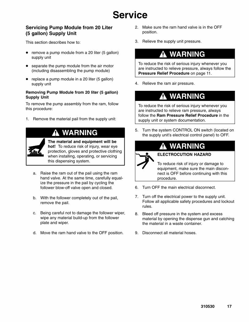
ServiceServicing Pump Module from 20 Liter(5 gallon) Supply Unit
This section describes how to:
� remove a pump module from a 20 liter (5 gallon)supply unit
� separate the pump module from the air motor(including disassembling the pump module)
� replace a pump module in a 20 liter (5 gallon)supply unit
Removing Pump Module from 20 liter (5 gallon)Supply Unit
To remove the pump assembly from the ram, followthis procedure:
1. Remove the material pail from the supply unit:
WARNINGThe material and equipment will behot! To reduce risk of injury, wear eyeprotection, gloves and protective clothingwhen installing, operating, or servicingthis dispensing system.
a. Raise the ram out of the pail using the ramhand valve. At the same time, carefully equal-ize the pressure in the pail by cycling thefollower blow-off valve open and closed.
b. With the follower completely out of the pail,remove the pail.
c. Being careful not to damage the follower wiper,wipe any material build-up from the followerplate and wiper.
d. Move the ram hand valve to the OFF position.
2. Make sure the ram hand valve is in the OFFposition.
3. Relieve the supply unit pressure.
WARNINGTo reduce the risk of serious injury whenever youare instructed to relieve pressure, always follow thePressure Relief Procedure on page 11.
4. Relieve the ram air pressure.
WARNINGTo reduce the risk of serious injury whenever youare instructed to relieve ram pressure, alwaysfollow the Ram Pressure Relief Procedure in thesupply unit or system documentation.
5. Turn the system CONTROL ON switch (located onthe supply unit’s electrical control panel) to OFF.
WARNINGELECTROCUTION HAZARD
To reduce risk of injury or damage toequipment, make sure the main discon-nect is OFF before continuing with thisprocedure.
6. Turn OFF the main electrical disconnect.
7. Turn off the electrical power to the supply unit.Follow all applicable safety procedures and lockoutrules.
8. Bleed off pressure in the system and excessmaterial by opening the dispense gun and catchingthe material in a waste container.
9. Disconnect all material hoses.
18 310530
ServiceRemoving Pump Module from 20 Liter (5 gallon)Supply Unit (continued)
1. Fig. 9. RTV sealant on the pump shrouds maymake it difficult to remove individual shroudpieces (8) and (A). Using a knife or razor, scrapethe sealant off of the seams of the shrouds.
2. Fig. 9, Fig. 14 (480/575 VAC) and Fig.15(240 VAC). Disconnect the junction box from thepump module and ) by:
a. Removing the cover of the junction box (9).
b. Disconnecting the heater wires and sensorwires that come from the pump.
c. Removing the wires from the junction box.
d. Disconnecting the pump’s back shroud (A) andmoving it backwards out of the way.
Fig. 9
7
8
9
A
3. Remove the follower from the pump by:
a. Removing the sensor from the follower plate.
b. Removing the air line from the blow-off valve.
c. Removing the bolts from the follower adapter.
d. Sliding off the follower.
4. Separate the pump from the air motor. Go to thenext section, Separating the 20 Liter (5 Gallon)Pump Module from the Air Motor.
19310530
Service
Fig. 10
10
20
30
40
1
2
50
70
60
80
90
100
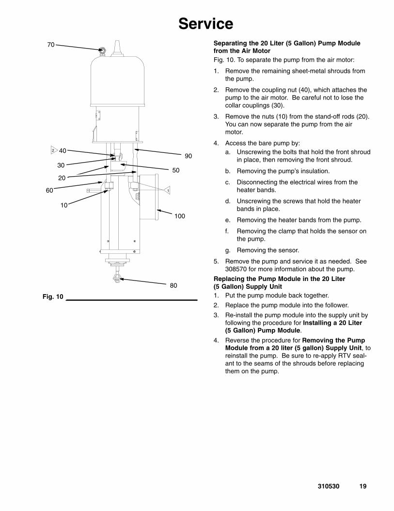
Separating the 20 Liter (5 Gallon) Pump Modulefrom the Air MotorFig. 10. To separate the pump from the air motor:
1. Remove the remaining sheet-metal shrouds fromthe pump.
2. Remove the coupling nut (40), which attaches thepump to the air motor. Be careful not to lose thecollar couplings (30).
3. Remove the nuts (10) from the stand-off rods (20).You can now separate the pump from the airmotor.
4. Access the bare pump by:a. Unscrewing the bolts that hold the front shroud
in place, then removing the front shroud.
b. Removing the pump’s insulation.
c. Disconnecting the electrical wires from theheater bands.
d. Unscrewing the screws that hold the heaterbands in place.
e. Removing the heater bands from the pump.
f. Removing the clamp that holds the sensor onthe pump.
g. Removing the sensor.
5. Remove the pump and service it as needed. See308570 for more information about the pump.
Replacing the Pump Module in the 20 Liter(5 Gallon) Supply Unit1. Put the pump module back together.
2. Replace the pump module into the follower.
3. Re-install the pump module into the supply unit byfollowing the procedure for Installing a 20 Liter(5 Gallon) Pump Module.
4. Reverse the procedure for Removing the PumpModule from a 20 liter (5 gallon) Supply Unit, toreinstall the pump. Be sure to re-apply RTV seal-ant to the seams of the shrouds before replacingthem on the pump.
20 310530
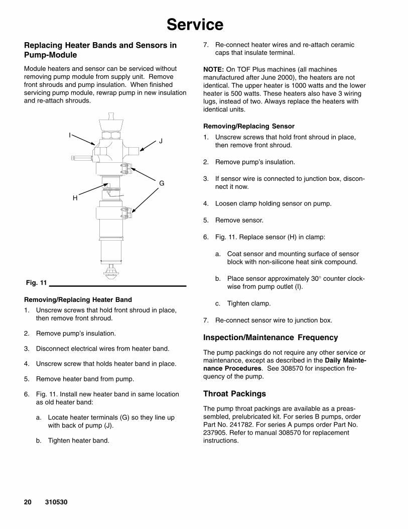
ServiceReplacing Heater Bands and Sensors inPump-Module
Module heaters and sensor can be serviced withoutremoving pump module from supply unit. Removefront shrouds and pump insulation. When finishedservicing pump module, rewrap pump in new insulationand re-attach shrouds.
Fig. 11
G
H
IJ
Removing/Replacing Heater Band
1. Unscrew screws that hold front shroud in place,then remove front shroud.
2. Remove pump’s insulation.
3. Disconnect electrical wires from heater band.
4. Unscrew screw that holds heater band in place.
5. Remove heater band from pump.
6. Fig. 11. Install new heater band in same locationas old heater band:
a. Locate heater terminals (G) so they line upwith back of pump (J).
b. Tighten heater band.
7. Re-connect heater wires and re-attach ceramiccaps that insulate terminal.
NOTE: On TOF Plus machines (all machinesmanufactured after June 2000), the heaters are notidentical. The upper heater is 1000 watts and the lowerheater is 500 watts. These heaters also have 3 wiringlugs, instead of two. Always replace the heaters withidentical units.
Removing/Replacing Sensor
1. Unscrew screws that hold front shroud in place,then remove front shroud.
2. Remove pump’s insulation.
3. If sensor wire is connected to junction box, discon-nect it now.
4. Loosen clamp holding sensor on pump.
5. Remove sensor.
6. Fig. 11. Replace sensor (H) in clamp:
a. Coat sensor and mounting surface of sensorblock with non-silicone heat sink compound.
b. Place sensor approximately 30° counter clock-wise from pump outlet (I).
c. Tighten clamp.
7. Re-connect sensor wire to junction box.
Inspection/Maintenance Frequency
The pump packings do not require any other service ormaintenance, except as described in the Daily Mainte-nance Procedures. See 308570 for inspection fre-quency of the pump.
Throat Packings
The pump throat packings are available as a preas-sembled, prelubricated kit. For series B pumps, orderPart No. 241782. For series A pumps order Part No.237905. Refer to manual 308570 for replacementinstructions.
21310530
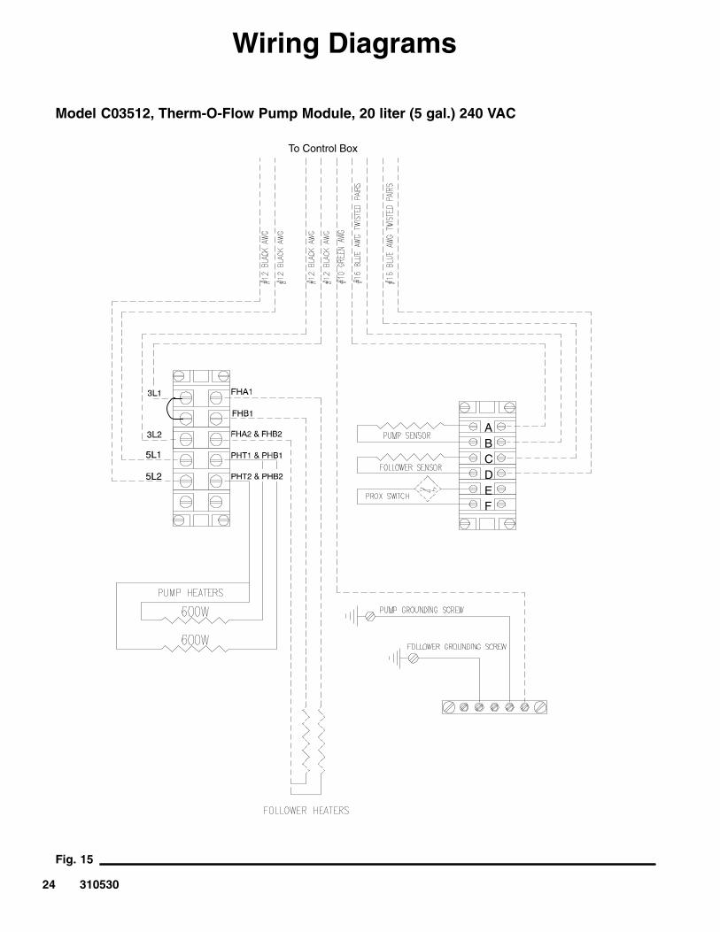
Wiring Diagrams
Fig. 12TI0673
Therm-O-Flow Plus Pump Module with 3 lug heaters, 200 liter (55 gal.)Model 243276, Series A Heated Pump, 240 VAC Supply Units – (used on Therm-O-Flow 55, June 2000 and after)
22 310530
Wiring Diagrams
Fig. 13TI0673
Therm-O-Flow Plus Pump Module with 3 lug heaters, 200 liter (55 gal.)Model 243276, Series A Heated Pump, 400, 480 and 575 VAC Supply Units – (used on Therm-O-Flow 55, June 2000 and after)
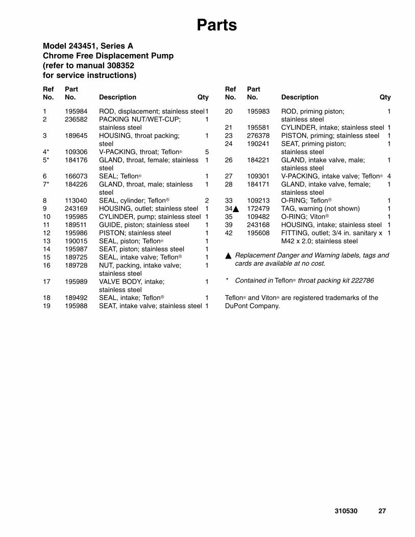
� Replacement Danger and Warning labels, tags andcards are available at no cost.
* Contained in Teflon� throat packing kit 222786
Teflon� and Viton� are registered trademarks of theDuPont Company.
28 310530
Parts
Ram
Pla
teS
enso
r
Ram
Pla
te2n
d S
enso
r(O
ptio
nal)
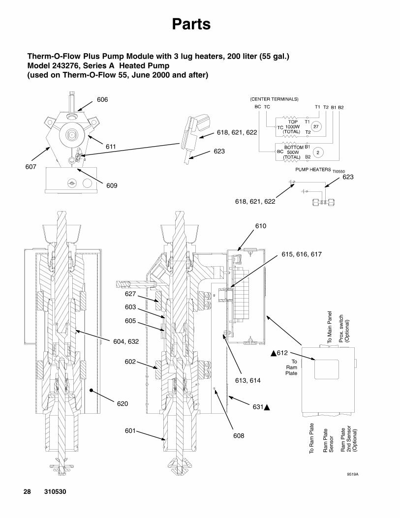
604, 632
620
ToRamPlate
To M
ain
Pan
el
Pro
x. s
witc
h(O
ptio
nal)
To R
am P
late
627
603
605
602
613, 614
615, 616, 617
618, 621, 622
606
611
609
607
608601
610
�612
9519A
623
631�
618, 621, 622
623TI0550
Therm-O-Flow Plus Pump Module with 3 lug heaters, 200 liter (55 gal.)Model 243276, Series A Heated Pump(used on Therm-O-Flow 55, June 2000 and after)
29310530
PartsTherm-O-Flow Plus Pump Module with 3 lug heaters, 200 liter (55 gal.)Model 243276, Series A Heated Pump(used on Therm-O-Flow 55, June 2000 and after)
Therm-O-Flow Plus 55 Air-Powered Ram Heated Supply Unit 309085
Therm-O-Flow 5 Air-Powered Ram Heated Supply Unit 310528
King Air Motor, 65:1 309347
Quiet King Air Motor, 65:1 309348
Bulldog Air Motor, 31:1 307049
Quiet Bulldog Air Motor, 31:1 307304
Senator Air Motor, 19:1 and Quiet Senator Air Motor, 19:1 307592
Throat Packing Kit 241782 314934
Check-Mate, King, and Quiet King are trademarks of Graco, Inc.Bulldog, Quiet Bulldog, Senator, Quiet Senator, and Therm-O-Flow are registered trademarks of Graco, Inc.
34 310530
Graco Standard WarrantyGraco warrants all equipment manufactured by Graco and bearing its name to be free from defects in material and workmanship on thedate of sale by an authorized Graco distributor to the original purchaser for use. With the exception of any special, extended, or limitedwarranty published by Graco, Graco will, for a period of twelve months from the date of sale, repair or replace any part of the equipmentdetermined by Graco to be defective. This warranty applies only when the equipment is installed, operated and maintained in accor-dance with Graco’s written recommendations.
This warranty does not cover, and Graco shall not be liable for general wear and tear, or any malfunction, damage or wear caused byfaulty installation, misapplication, abrasion, corrosion, inadequate or improper maintenance, negligence, accident, tampering, or sub-stitution of non–Graco component parts. Nor shall Graco be liable for malfunction, damage or wear caused by the incompatibility ofGraco equipment with structures, accessories, equipment or materials not supplied by Graco, or the improper design, manufacture,installation, operation or maintenance of structures, accessories, equipment or materials not supplied by Graco.
This warranty is conditioned upon the prepaid return of the equipment claimed to be defective to an authorized Graco distributor forverification of the claimed defect. If the claimed defect is verified, Graco will repair or replace free of charge any defective parts. Theequipment will be returned to the original purchaser transportation prepaid. If inspection of the equipment does not disclose any defectin material or workmanship, repairs will be made at a reasonable charge, which charges may include the costs of parts, labor, andtransportation.
THIS WARRANTY IS EXCLUSIVE, AND IS IN LIEU OF ANY OTHER WARRANTIES, EXPRESS OR IMPLIED, INCLUDING BUTNOT LIMITED TO WARRANTY OF MERCHANTABILITY OR WARRANTY OF FITNESS FOR A PARTICULAR PURPOSE.
Graco’s sole obligation and buyer’s sole remedy for any breach of warranty shall be as set forth above. The buyer agrees that no otherremedy (including, but not limited to, incidental or consequential damages for lost profits, lost sales, injury to person or property, or anyother incidental or consequential loss) shall be available. Any action for breach of warranty must be brought within two (2) years of thedate of sale.
Graco makes no warranty, and disclaims all implied warranties of merchantability and fitness for a particular purpose in connectionwith accessories, equipment, materials or components sold but not manufactured by Graco. These items sold, but not manufacturedby Graco (such as electric motors, switches, hose, etc.), are subject to the warranty, if any, of their manufacturer. Graco will providepurchaser with reasonable assistance in making any claim for breach of these warranties.
In no event will Graco be liable for indirect, incidental, special or consequential damages resulting from Graco supplying equipmenthereunder, or the furnishing, performance, or use of any products or other goods sold hereto, whether due to a breach of contract,breach of warranty, the negligence of Graco, or otherwise.
FOR GRACO CANADA CUSTOMERSThe parties acknowledge that they have required that the present document, as well as all documents, notices and legal proceedingsentered into, given or instituted pursuant hereto or relating directly or indirectly hereto, be drawn up in English. Les parties reconnais-sent avoir convenu que la rédaction du présente document sera en Anglais, ainsi que tous documents, avis et procédures judiciairesexécutés, donnés ou intentés à la suite de ou en rapport, directement ou indirectement, avec les procedures concernées.
Graco InformationTO PLACE AN ORDER, contact your Graco distributor, or call one of the following numbers
to identify the distributor closest to you:1–800–367–4023 Toll Free
612–623–6921612–378–3505 Fax
All written and visual data contained in this document reflects the latest product information available at the time of publication.Graco reserves the right to make changes at any time without notice.
Sales Offices: Minneapolis, DetroitInternational Offices: Belgium, Korea, Hong Kong, Japan
www.graco.comPRINTED IN USA 310530 03/1996, Revised 08/2002


![Therm L1 [Basics]](https://static.documents.pub/doc/80x56/577d276d1a28ab4e1ea3e5da/therm-l1-basics.jpg)
