The following warnings are for the setup, use, grounding, maintenance, and repair of this equipment. The exclama-tion point symbol alerts you to a general warning and the hazard symbol refers to procedure-specific risk. Refer back to these warnings. Additional, product-specific warnings may be found throughout the body of this manual where applicable.
WARNING
WARNING: a potentially hazardous situation which, if not avoided, could result in death or serious injury.
Warnings in the instructions usually include a symbol indicating the hazard. Read the general Warnings section for additional safety information.
CAUTIONCAUTION: a potentially hazardous situation which, if not avoided, may result in property damage or destruc-tion of equipment.
Additional helpful information.
WarningFIRE AND EXPLOSION HAZARD Flammable fumes, such as solvent and paint fumes, in work area can ignite or explode. To help prevent fire and explosion:• Use equipment only in well ventilated area.• When flammable liquid is sprayed or used for flushing or cleaning, keep sprayer at least 20 feet (6 m)
away from explosive vapors.• Eliminate all ignition sources; such as pilot lights, cigarettes, portable electric lamps, and plastic drop
cloths (potential static arc). • Keep work area free of debris, including solvent, rags and gasoline.• Do not plug or unplug power cords, or turn power or light switches on or off when flammable fumes
are present.• Ground equipment and conductive objects in work area. See Grounding instructions.• Use only grounded hoses.• Hold gun firmly to side of grounded pail when triggering into pail.• If there is static sparking or you feel a shock, stop operation immediately. Do not use equipment
until you identify and correct the problem.• Keep a fire extinguisher in the work area.
PRESSURIZED EQUIPMENT HAZARD Fluid from the gun/dispense valve, leaks, or ruptured components can splash in the eyes or on skin and cause serious injury.• Follow Pressure Relief Procedure in this manual, when you stop spraying and before cleaning,
checking, or servicing equipment. • Tighten all fluid connections before operating the equipment.• Check hoses, tubes, and couplings daily. Replace worn or damaged parts immediately.
Manual Conventions
4 311163K
EQUIPMENT MISUSE HAZARD Misuse can cause death or serious injury.• Do not exceed the maximum working pressure or temperature rating of the lowest rated system com-
ponent. See Technical Data in all equipment manuals.• Use fluids and solvents that are compatible with equipment wetted parts. See Technical Data in all
equipment manuals. Read fluid and solvent manufacturer’s warnings.• Check equipment daily. Repair or replace worn or damaged parts immediately.• Do not alter or modify equipment.• For professional use only.• Use equipment only for its intended purpose. Call your Graco distributor for information.• Route hoses and cables away from traffic areas, sharp edges, moving parts, and hot surfaces.• Do not kink or over bend hoses or use hoses to pull equipment.• Comply with all applicable safety regulations.
MOVING PARTS HAZARD Moving parts can pinch or amputate fingers and other body parts.• Keep clear of moving parts.• Do not operate equipment with protective guards or covers removed.• Pressurized equipment can start without warning. Before checking, moving, or servicing equipment,
follow the Pressure Relief Procedure in this manual. Disconnect power or air supply.
TOXIC FLUID OR FUMES HAZARD Toxic fluids or fumes can cause serious injury or death if splashed in the eyes or on skin, inhaled, or swal-lowed.• Read MSDS’s to know the specific hazards of the fluids you are using.• Store hazardous fluid in approved containers, and dispose of it according to applicable guidelines.
PERSONAL PROTECTIVE EQUIPMENT You must wear appropriate protective equipment when operating, servicing, or when in the operating area of the equipment to help protect you from serious injury, including eye injury, inhalation of toxic fumes, burns, and hearing loss. This equipment includes but is not limited to:• Protective eyewear • Clothing and respirator as recommended by the fluid and solvent manufacturer• Gloves• Hearing protection
Warning
Overview
311163K 5
Overview
Related Publications
Operation OverviewThe BES 300 evacuates fluids from a 300 gallon (1135 liter) bag in a plywood box or collapsible bin.
The BES 300 consists of a frame, two or four Graco pumps, ram plate with an inflatable seal, ram air cylin-der, and a manual or electronic control panel.
Basic Operation of BES 3001. The operator places the bin inside the frame.
2. Using the control panel, the operator lowers the ram plate on top of the material.
3. The operator inflates the ram plate seal, applies down pressure to the ram plate, and turns on the pumps.
4. The pumps evacuate the material out of the bin.
5. The operator stops the pumps, deflates the seal, and raises the ram plate out of the bin.
6. The empty bin is removed, another bin is put in place, and the BES 300 is ready to repeat the pro-cess.
306916 Bulldog® and King® Pumps
307592 Senator® and Quiet Senator® Air Motors
308076 FT14 Sanitary and Senator® Pumps
308149 Bulldog® and King® Pumps
310622 3150 Sanitary Husky® Pumps
Overview
6 311163K
System Components (Manual Control)See FIG. 1.
A Stainless Steel Frame: supports the cardboard or collapsible bin.
B Manual Control Panel: contains pneumatic controls to regulate the air pressure to pump air motors, ram, and ram plate seal in order to control:
• pump air motor pressure• pump speed control• ram up and down pressure• seal pressure• turn the pumps on or off• inflate or deflate the ram plate seal• raise or lower the ram plate
C Air Shutoff Valve: shuts off air to the pneumatic control panel (B).
D Sanitary Pumps: pump material from the bin to the target application.
E Air Cylinder: raises and lowers the pumps and the ram plate in and out of the material container.
F Ram Plate: applies an even amount of pressure to the material in the bin. When the ram plate seal is inflated, it creates a seal. The ram plate presses down on the material in the bin to assist the pumps in delivering the material.
A Stainless Steel Frame: supports the cardboard or collapsible bin.
B Pneumatic Control Panel: contains pneumatic controls to regulate the air pressure to pump air motors, ram, and ram plate seal in order to control:
• pump air motor pressure• pump speed control• ram up and down pressure• seal pressure
C Electronic Control Panel: is connected to the pneumatic control panel with the 24 VDC cable supplied. The panel uses 110 VAC input (20 amp circuit). If a flow meter is used, it must also be connected. The electronic control panel sends signals to:
• turn the pumps on or off• inflate or deflate the ram plate seal• raise or lower the ram plate• turn off the air supply to the ram plate so the
ram can slowly lower into the bin
D Sanitary Pumps: pump material from the bin to the target application.
E Air Cylinder: raises and lowers the pumps and the ram plate in and out of the material container.
F Ram Plate: applies an even amount of pressure to the material in the bin. When the ram plate seal is inflated, it creates a seal. The ram plate presses down on the material in the bin to assist the pumps in delivering the material.
1. Inspect the crate for shipping damage. Contact the carrier if damaged.
2. Remove plywood sides and top of crate.
3. Check the contents for loose or damaged parts.
4. Compare the packing slip against items inside the crate. Immediately call your Graco distributor about any shortages or damage.
5. Remove the band strap holding the cylinder bin to the frame.
6. Remove and unpack the air cylinder bin and pumps (if applicable).
LocationWhen selecting a location, make sure the location:
• Is close to where the fluid is being delivered to mini-mize back pressure and maximize flow rate.
• Provides enough room around the equipment for maintenance.
• Does not interfere with opening the pneumatic con-trol panel door or frame door (on one or both sides). If the frame is rotated 180°, the frame door will open from left to right or from right to left. There are extra holes in the frame to mount the control panel on either side.
• Provides enough room on the right and/or left side of the BES 300 to easily load and unload fluid bins with a forklift or pallet-jack hand truck.
• Provides easy and safe access to the air supply shutoff valves and the pneumatic control panel. Graco recommends a minimum of 3 ft (0.91 m) of open space in front of the panel.
• Provides enough overhead clearance (11 ft, 3.4 m recommended) for installing and servicing the air cylinder and connecting air supply lines to the pneu-matic control panel.
• Has a flat, level floor.
Moving Frame to Location
• Do not remove the frame from the pallet at this time.
• Use a forklift or hand truck and support devices, such as a hoist, and have an adequate number of personnel to move the frame to the installation site.
• Avoid jarring or tilting the frame while moving it.
CAUTION
Moving the BES 300 off the pallet without following this uncrating procedure will damage equipment.
See Related Publications, page 5, to become familiar with system components and general operation.
WARNING
The frame is shipped with several major components attached and weighs about 2500 lb. (1134 kg). To avoid injury and equipment damage, follow instruc-tions below. Never have one person move or lift the frame. Read warnings, page 4.
• Ensure there is an adequate compressed air supply. Refer to air motor/pump manual for your pump air consumption. About 250-300 scfm at 100 psi (0.7 MPa, 7 bar) is required to operate the pumps at the maximum rate.
• Have all component manuals available for specific component requirements. See Related Publications, page 5.
• Ensure that all hoses are properly sized and pressure rated for the system.
Installation
311163K 9
Installation
Anchoring FrameThe frame must be level in order for the BES 300 to operate properly. If necessary, level the BES 300 using metal shims. Make sure the frame does not wobble.
Anchor the four foot pads to the floor. To prevent the frame from being pushed off the floor, the anchor bolts must be long enough to withstand the 5027 lb. (22.36 kN) of downward force that the air cylinder can exert.
Use the holes in the four base footings as a guide and drill holes for 1/2 in. (13 mm) bolts. Bolt the frame to the floor with anchors.
Installing Air Cylinder
1. Remove the screws (405) and washers (411) attached to the motor mounting rods (404), and remove the air motor mounting plate (402). See FIG. 4.
2. Using a hoist, lift the air cylinder (4) into position on top of the frame (602). See FIG. 3.
3. Lower the air cylinder shaft (A) through the center hole in the frame.
4. Secure the air cylinder (4) to the frame (602) with the screws (20) and washers (19). See FIG. 4.
5. Loosen but do not remove the screws (18) from the frame (602).
6. Remove the two band straps that hold the ram plate (502) to the shipping pallet. Do not remove the pal-let.
7. Apply sanitary grease (36, supplied) to the cylinder shaft threads to avoid damaging them. Align and screw the air cylinder shaft (A) into the ram plate (502). See FIG. 3. If the shaft does not thread prop-erly, do not force it. Re-check alignment of plate (502).
WARNING
The air cylinder weighs about 130 lb. (59 kg). To avoid injury and equipment damage, follow instructions below. Never have one person move or lift the frame. Read warnings, page 4.
All models do not use the same parts. Refer to parts lists for your model, pages 32-41.
FIG. 3: Air Cylinder Shaft
4
602A
TI3116A
Installation
10 311163K
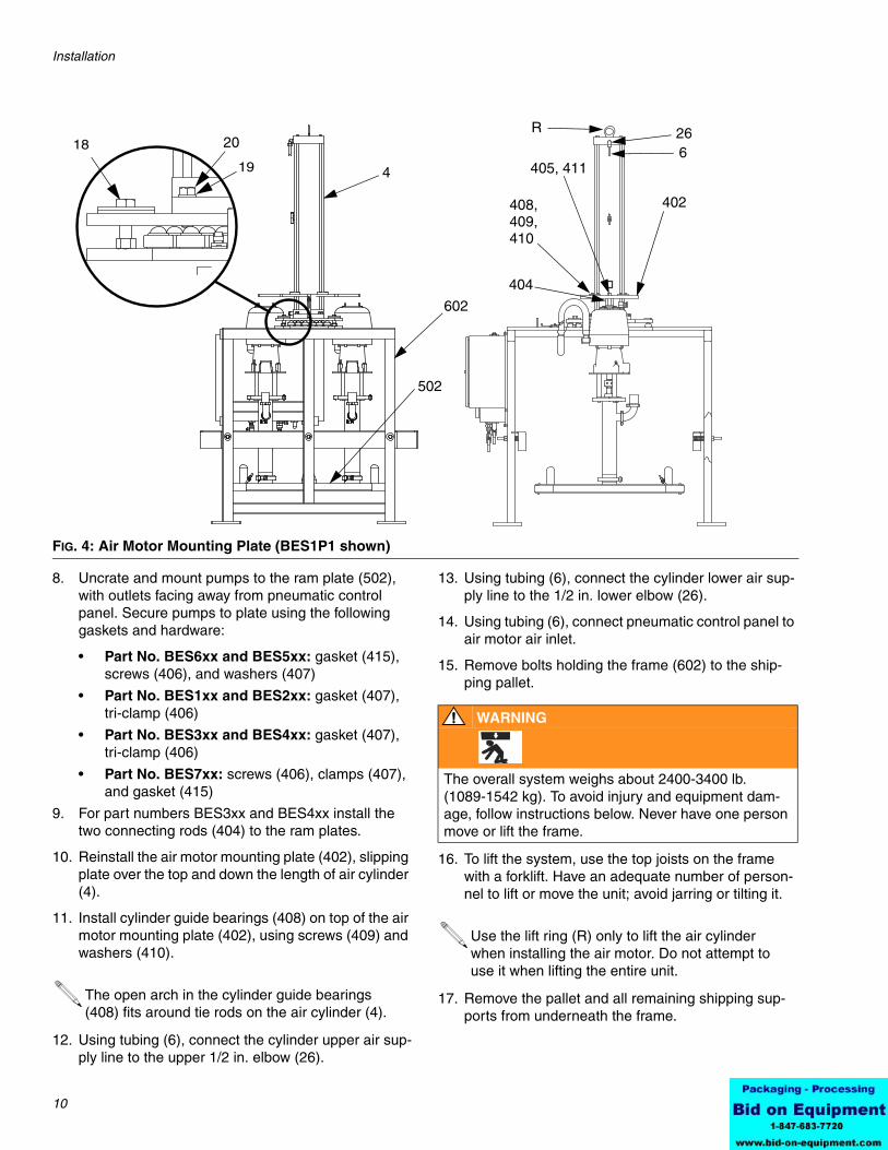
8. Uncrate and mount pumps to the ram plate (502), with outlets facing away from pneumatic control panel. Secure pumps to plate using the following gaskets and hardware:
• Part No. BES6xx and BES5xx: gasket (415), screws (406), and washers (407)
• Part No. BES1xx and BES2xx: gasket (407), tri-clamp (406)
• Part No. BES3xx and BES4xx: gasket (407), tri-clamp (406)
• Part No. BES7xx: screws (406), clamps (407), and gasket (415)
9. For part numbers BES3xx and BES4xx install the two connecting rods (404) to the ram plates.
10. Reinstall the air motor mounting plate (402), slipping plate over the top and down the length of air cylinder (4).
11. Install cylinder guide bearings (408) on top of the air motor mounting plate (402), using screws (409) and washers (410).
12. Using tubing (6), connect the cylinder upper air sup-ply line to the upper 1/2 in. elbow (26).
13. Using tubing (6), connect the cylinder lower air sup-ply line to the 1/2 in. lower elbow (26).
14. Using tubing (6), connect pneumatic control panel to air motor air inlet.
15. Remove bolts holding the frame (602) to the ship-ping pallet.
16. To lift the system, use the top joists on the frame with a forklift. Have an adequate number of person-nel to lift or move the unit; avoid jarring or tilting it.
17. Remove the pallet and all remaining shipping sup-ports from underneath the frame.
FIG. 4: Air Motor Mounting Plate (BES1P1 shown)
405, 411
26
4
602
408,409,410
402
502
18 20
196
404
R
The open arch in the cylinder guide bearings (408) fits around tie rods on the air cylinder (4).
WARNING
The overall system weighs about 2400-3400 lb. (1089-1542 kg). To avoid injury and equipment dam-age, follow instructions below. Never have one person move or lift the frame.
Use the lift ring (R) only to lift the air cylinder when installing the air motor. Do not attempt to use it when lifting the entire unit.
Installation
311163K 11
Connecting Pump Output HosesTwo Pump System Includes:
Four Pump System Includes:
• See Related Publications, page 5, for air motor/pump instruction manual numbers.
• The output hose(s) (supplied by others) should already be installed, with riggings and supports, and ready for connection to the 2 in. tri-clamp (412, supplied on some systems). See FIG. 5.
• Make sure the output hose(s) are sized and pressure-rated for the system. Use only elec-trically conductive hoses with spring guards on both ends.
The fluid hoses must move freely, without kinking, when the pumps move up and down.
The two pump AODD and the King ink pump sys-tems do not include a hose, clamps, or gaskets on the outlet side.
Description Qty
2 in. (51 mm) tri-clamp sanitary clamps (412)
4 or 6
2 in. (51 mm) tri-clamp sanitary gaskets (413)
4 or 6
Description Qty
2 in. (51 mm) tri-clamp sanitary clamps (412)
8 or 12
2 in. (51 mm) tri-clamp sanitary gaskets (413)
8 or 12
FIG. 5: Connect pump outlet hoses (BES1P1 shown)
406, 407
Installation
12 311163K
Grounding
Pump: use the ground wire and clamp (supplied). There are two styles of grounding connections on pump air motors.
If you have ground screw shown in FIG. 6, you need to order part no. 222011 ground wire, ring terminal, and clamp assembly (Y). To install 222011, remove the ground screw (Z) and insert it through the eye of ring ter-minal (X), then tighten ground screw back into air motor as shown in FIG. 6. Connect the other end of the wire to a true earth ground.
If you have ground screw shown in FIG. 7, loosen the grounding lug locknut (W) and washer (X). Insert one end of the ground wire (Y) into the slot in lug (Z) and tighten the locknut securely. Connect the other end of the wire to a true earth ground. Order 237569 ground wire and clamp assembly.
Air and fluid hoses: use only electrically conductive hoses with a maximum of 500 ft (150 m) combined hose length to ensure grounding continuity. Check the electri-cal resistance of your air and fluid hoses. If the total resistance to ground exceeds 29 megohms, replace the hose immediately.
Air compressor: follow manufacturer’s recommenda-tions.
Dispense valve: ground through connection to a prop-erly grounded fluid hose and pump.
Fluid supply container: follow your local code.
Solvent pails used when flushing: follow your local code. Use only conductive, metal pails, placed on a grounded surface. Do not place the pail on a noncon-ductive surface, such as paper or cardboard, which interrupts grounding continuity.
To maintain grounding continuity when flushing or relieving pressure: hold a metal part of the dispense valve firmly to the side of a grounded metal pail, then trigger the gun/valve.
Checking ResistanceHave a qualified electrician check the resistance between each pump and true earth ground. Resistance must be less than 0.25 ohms. If the resistance is greater, a different ground site may be required. Do not operate the system until you correct the problem.
Prepare the OperatorAnyone operating the equipment must be trained to safely operate all system components and properly han-dle fluids used. Operators must read all instruction man-uals, tags, and labels before operating equipment.
WARNING
The system must be properly grounded. Read warn-ings, page 3. Follow the instructions below.
FIG. 6: Ground Screw
FIG. 7: Ground Screw
YZ
X
W
XY
Z
Manual Stop (all models)
311163K 13
Manual Stop (all models)
Engaging1. Raise plate until it stops at the top.
2. Set latch to closed position. See FIG. 8.
Disengaging1. Make sure plate is raised all the way up (not resting
on stop).
2. Move latch to open position. See FIG. 8.
WARNING
The overall system weighs about 2400-3400 lb. (1089-1542 kg). To avoid injury, always set manual stop latch to closed position when working under the plate.
FIG. 8. Manual Stop (BES1P1 shown)
Closed Position
Open Position
Manual Control System
14 311163K
Manual Control System
Part No. 15E523 Manual Control See FIG. 9.
Ref. Key Switch/Button Name Operation
A Seal Inflate On/Off Switch to ON to inflate ram plate seal.
Switch to OFF to deflate ram plate seal.
B Ram Plate Seal Pressure Gauge Displays Ram plate seal pressure.
C Ram Plate Seal Regulator Adjust to raise or lower ram plate seal pressure.
D Pump On/Off Switch to ON to run the pumps.
Switch to OFF to stop the pumps.
E Pump Pressure Gauge Displays current pump pressure.
F Pump Pressure Regulator Adjust to raise or lower pump inlet air pressure.
G Ram Directional Switch Switch to UP to raise the ram plate.
Switch to DOWN to apply ram pressure to the material.
Switch to NEUTRAL to hold the position of the ram plate.
H Ram Up Pressure Gauge Displays Ram Up operation pressure.
J Ram Up Regulator Adjust to raise or lower ram up pressure.
K Ram Down Pressure Gauge Displays Ram Down operation pressure.
L Ram Down Regulator Adjust to raise or lower ram down pressure.
FIG. 9: Part No. 15E523 Manual Control
BA
D
G
L
K
J
H
F
E
C
Tee is used on four pump systems only
Manual Control System
311163K 15
Pressure Relief Procedure
1. To turn off the pumps move pump switch to OFF.
2. Shut off the air to the pumps by closing the bleed-type air shutoff valve on the pumps’ air supply line, or disconnect the air line.
3. Open all system fluid drain valves that are down-stream of the pumps.
Initial Startup
This procedure takes you through the settings, adjust-ments, and other steps that must be completed before the system is ready for daily operation.
1. Fill all the pumps packing nut/wet cups 1/3 full with a compatible lubricant if applicable. Refer to your pump manual for details. Do not use Graco Throat Seal Lubricant with a sanitary application.
2. Turn on the air to the pneumatic control panel.
3. Turn SEAL INFLATE to OFF.
4. Open the air shutoff valves for the pneumatic con-trols and pumps.
5. Open the pneumatic control panel door. Check for air leaks.
6. The equipment was tested with water. Flush the system before loading material. See page 26.
7. Follow Loading the Bin procedure, page 16.
8. Set the ram down air regulator to 30 psi (207 kPa, 2.1 bar). Adjust as needed.
9. Adjust the pump regulator as needed.
10. Adjust the seal vacuum pump air regulator to 15 psi (103 kPa, 1.0 bar).
11. Deflate the seal.
12. Press the RAM UP button. If the ram does not raise, increase the ram up air regulator pressure.
13. Verify the seal is completely deflated after the ram plate exits the bin. If it is not, deflate the seal.
14. When adjustments are complete, close the pneu-matic control panel door.
15. Follow Unloading the Bin procedure, page 16.
16. The system is now ready for standard operation. See page 15.
Setting Air PressuresEach system function has an associated air pressure. Air pressure regulators are located on the pneumatic control panel. Set initial air pressures as shown in the table below. Make adjustments as needed during opera-tion. See FIG. 9.
WARNING
Read warnings, page 3, and follow the Pressure Relief Procedure whenever you:• are instructed to relieve pressure• stop operation• check, clean, or service any of the equipment
WARNING
When raising or lowering the ram plate, keep hands and body away from ram plate and bin lip. Read warn-ings, page 4.
Pump Cavitation
Pump cavitation occurs when the pump cylinder does not fully load with material on the up stroke and an air pocket forms in the material after the pump changeover. If pump cavitation occurs, increase the ram down air pressure.
Ref. Key
Function Regulator Settingpsi (kPa, bar)
B SEAL INFLATE 15 (103, 1.0)
H RAM UP 30 (207, 2.1)
K RAM DOWN 30 (207, 2.1)
E PUMP 50 (345, 3.4)
Manual Control System
16 311163K
Standard Operation
Loading the Bin
1. Open the air shutoff valves for the air controls and pumps.
2. On the control panel, switch to the RAM UP posi-tion. If the ram does not elevate, increase the ram up air regulator pressure on the pneumatic control panel.
3. Move the bin in front of the frame.
4. Remove the lid from the fluid bin to expose the fluid bag. If present, open the outer plastic bag and pull it up over the sides of the bin, exposing the aseptic inner bag.
5. Make sure the bag is taut and secure it in place.
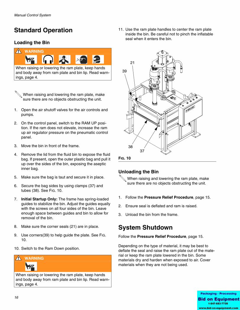
6. Secure the bag sides by using clamps (37) and tubes (38). See FIG. 10.
7. Initial Startup Only: The frame has spring-loaded guides to stabilize the bin. Adjust the guides equally with the screws on all four sides of the bin. Leave enough space between guides and bin to allow for removal of the bin.
8. Make sure the corner seals (21) are in place.
9. Use corners(39) to help guide the plate. See FIG. 10.
10. Switch to the Ram Down position.
11. Use the ram plate handles to center the ram plate inside the bin. Be careful not to pinch the inflatable seal when it enters the bin.
Unloading the Bin
1. Follow the Pressure Relief Procedure, page 15.
2. Ensure seal is deflated and ram is raised.
3. Unload the bin from the frame.
System ShutdownFollow the Pressure Relief Procedure, page 15.
Depending on the type of material, it may be best to deflate the seal and raise the ram plate out of the mate-rial or keep the ram plate lowered in the bin. Some materials dry and harden when exposed to air. Cover materials when they are not being used.
WARNING
When raising or lowering the ram plate, keep hands and body away from ram plate and bin lip. Read warn-ings, page 4.
When raising and lowering the ram plate, make sure there are no objects obstructing the unit.
WARNING
When raising or lowering the ram plate, keep hands and body away from ram plate and bin lip. Read warn-ings, page 4.
FIG. 10
When raising and lowering the ram plate, make sure there are no objects obstructing the unit.
3837
21
39
Electronic Control System
311163K 17
Electronic Control System
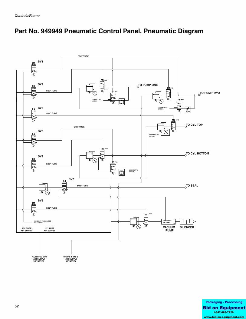
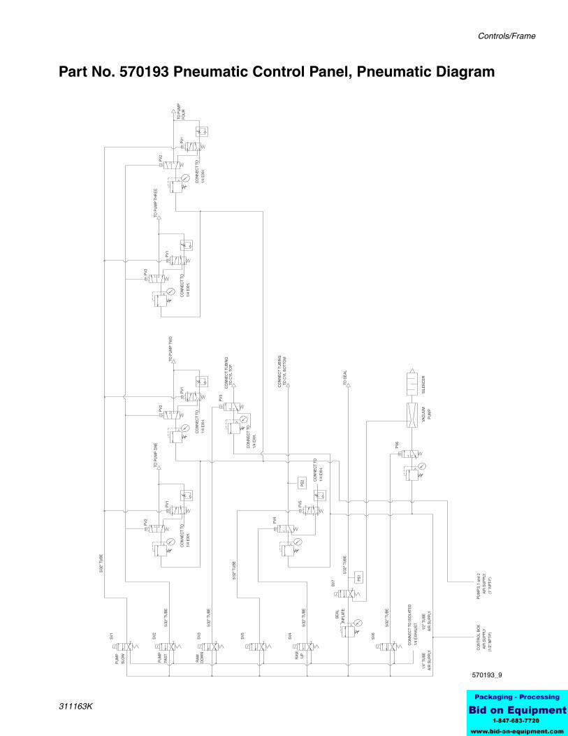
Connecting Pneumatic Control Panel Air LinesAir supply to panel must be filtered, dry and capable of delivering a minimum of 100 scfm at 100 psi (0.7 MPa, 7 bar). Refer to the table below and the Pneumatic Diagrams, pages 52 and 53, to make the top and bottom panel connec-tions.
Ref. Key Origin Destination
Top Panel Connections Component Connections Function
C Seal Air Supply Ram Plate Seal Inflates ram plate seal.
D Cylinder Upper Air Supply Upper Port On Air Cylinder Applies down force on ram plate when RAM PRESS is selected.
E Cylinder Lower Air Supply Lower Port On Air Cylinder Applies up force on ram plate when RAM UP is selected.
F Pump 1 Air Supply Pump 1 Supplies air to pump 1.*
G Pump 2 Air Supply Pump 2 Supplies air to pump 2.*
H Pump 3 Air Supply Pump 3 Supplies air to pump 3.*
J Pump 4 Air Supply Pump 4 Supplies air to pump 4.*
Air Controls Air Supply Line Supplies air to open and close air valves.
A Pumps Air Inlet — 1 in. npt(f) Pumps Air Supply Line Supplies input air pressure to pumps.
K Exhaust (no air line connection is needed)
Air Controls Exhaust Line Connects to a muffler that expels pressurized air from system when ram plate is raised or seal deflated.
* Pump air valves open when PUMP SLOW or PUMP FAST (SV1 or SV2) are activated.
FIG. 11: Air Control Panel (570193, 4 pump shown)
A B
Key:A Pumps 1-4 Air SupplyB Control Box Air SupplyC Seal AirD Ram Down AirE Ram Up AirF Pump 1 AirG Pump 2 AirH Pump 3 AirJ Pump 4 AirK Exhaust Muffler
C D E F G H J
ti10506a
KB
A
Electronic Control System
18 311163K
Installing Electronic Control Panel
Mount the electronic control panel in a level, vertical position on a sturdy surface. Make sure there is enough room to open the enclosure door.
Connect 110 VAC (20 amp) power to the POWER IN cable connector. The 110 VAC line must be rigidly piped.
Connect 24 VDC cable between the electronic and pneumatic control panels.
If a flow meter is used, its cable must also be connected to the electronic control panel. Contact the flow meter supplier for installation information.
Part No. 15H145 and 15J902 Electronic Control Panel
WARNING
Locate the electronic control panel so the operator has an unobstructed view of the BES 300 to avoid starting equipment when other personnel could be injured. Read warnings, page 4.
mode*Pump Fast. . . . . . . . . . . . Initiates pumps in fast
mode*
Digital Outputs 24 VDC
Pumps 1 and 2 On Slow . Solenoid 1Pumps 1 and 2 Fast . . . . Solenoid 2Ram Press . . . . . . . . . . . Solenoid 3Ram Up Solenoid 4Ram Jog Solenoid 5Seal Off (vacuum pump on). . . . . . . . . . . . . Solenoid 6Seal On. . . . . . . . . . . . . . Solenoid 7Optional Remote Output . Energized during a pump
cycle* Normally open
** Normally closed
Ref. Key Switch/Button Name Operation
A SEAL INFLATE Press to inflate ram plate seal
B RAM JOG Press button to slowly lower ram (by exhausting ram up air pressure). Generally used when guiding ram plate into bin or making system adjustments.
Electronic Control System
311163K 19
Proximity SwitchThe low limit proximity switch (641) is located near the air cylinder (mounting plate (15) and can be adjusted to operate at different levels in the bin. See FIG. 13.
The pumps operate in fast mode until the ram plate reaches the low limit. The proximity switch changes the
pumps to the slow mode operation for a user selected amount of time, after which the pumps stop, the seal deflates, and the ram raises.
C RAM UP Press button to raise ram.
D RAM PRESS Press button to lower ram onto material using air pres-sure.
E STOP Press button to stop operation of the pumps, ram and automatic cycle.*
F PUMP SPEED SWITCH Turn switch to select the pump speed.
G MODE SELECTOR SWITCH Turn switch to select the ram operation mode.
H EMERGENCY STOP Press button to immediately shut off air to the system and stop operation.*
J START Press button to begin operation.
K POWER Press button to enable power to the electronic control panel.
*The air cylinder will stabilize in its current position.
Ref. Key Switch/Button Name Operation
FIG. 12: Part No. 15H145 and 15J902 Electronic Control
R
A
B
C
D
EF G H
J
K
Electronic Control System
20 311163K
The system timer controls how long the pumps run at slow speed at the end of bin evacuation. After the time elapses, the controller stops the pumps, deflates the seal, and raises the ram up.
FIG. 13: Proximity Switch
4
641
15
See Setting the Bin Empty Timer and Setting the Vacuum Pump Timer, page 22, for additional information on adjusting the proximity switch and system timer.
Electronic Control System
311163K 21
Setting Air PressuresEach system function has an associated air pressure. Air pressure regulators are located in the pneumatic control bin. Set initial air pressures as shown in the table below. Make adjustments as needed during operation. See FIG. 14.
Ref. Function Regulator Settingpsi (kPa, bar)
A SEAL INFLATE 15 (103, 1.0)
B RAM UP 30 (207, 2.1)
C RAM DOWN 30 (207, 2.1)
D PUMP 1 50 (345, 3.4)
E PUMP 2 50 (345, 3.4)
F *PUMP 3 50 (345, 3.4)
G *PUMP 4 50 (345, 3.4)
H SEAL VACUUM 20 (138, 1.4)
* Four pump systems only.
FIG. 14: Part No 570193, 4 pump shown
A
BC D E F GH
ti10506a
Electronic Control System
22 311163K
Pressure Relief Procedure
1. Press the STOP button to turn off the pumps.
2. Shut off the air to the pumps by closing the bleed-type air shutoff valve on the pumps’ air supply line, or disconnect the air line.
3. Open all system fluid drain valves that are down-stream of the pumps.
Initial StartupThis procedure takes you through the settings, adjust-ments and other steps that must be completed before the system is ready for daily operation.
1. If applicable, fill all the pumps packing nut/wet cups 1/3 full with a compatible lubricant. Refer to your pump manual for details. Do not use Graco Throat Seal Lubricant with a sanitary application.
2. Press POWER button to turn on power to electronic control panel.
3. Turn SEAL to OFF.
4. Open the air shutoff valves for the pneumatic con-trols and pumps.
5. Open the pneumatic control panel door. Check for air leaks.
6. The equipment was tested with fluid. Flush the sys-tem before loading material. See page 26.
7. Follow Loading the Bin procedure, page 24.
Setting the Pump Slow Timer
The pump slow timer controls the amount of time that the pumps will operate at the slow speed for priming the pumps. This timer will be active when the plate is in the bin, the control is set to AUTO, the seal is inflated and the ram is pressurized down.
1. Press the Timer key to access the timer screens. Continue to toggle the key until the PUMP SLOW TIMER screen appears.
2. Press the Enter key to enable numerical entry.
3. Enter the desired set point - Minimum Value: 000, Maximum Value: 999. Example (300 = 30 sec).
4. Press the Enter key a second time to accept the value.
Setting the Bin Empty Timer
The bin empty timer controls the amount of time the pumps operate at the slow speed for emptying the bin. This timer will be activated when the ram is in AUTO mode and the proximity switch has been tripped.
1. Press the Timer key to access the timer screens. Continue to toggle the key until the BIN EMPTY TIMER screen appears.
2. Press the Enter key to enable numerical entry.
3. Enter the desired set point - Minimum Value: 000, Maximum Value: 999. Example (300 = 30 sec).
4. Press the Enter key a second time to accept the value.
Setting the Vacuum Pump Timer
The vacuum pump timer controls the amount of time the vacuum pump operates to assist the deflation of the seal. This timer will be activated when the ram is in AUTO mode and the proximity switch has been tripped.
1. Press the Timer key to access the timer screens. Continue to toggle the key until the VACUUM PUMP TIMER screen appears.
2. Press the Enter key to enable numerical entry.
3. Enter the desired set point - Minimum Value: 000, Maximum Value: 999. Example (300 = 30 sec).
4. Press the Enter key a second time to accept the value.
WARNING
Read warnings, page 3, and follow the Pressure Relief Procedure whenever you:• are instructed to relieve pressure• stop operation• check, clean, or service any of the equipment
Press STOP button at any time to stop the system. See FIG. 12.
Electronic Control System
311163K 23
Batch Mode Setup
The electrical control cabinet is designed to operate optional batching functions. The batch mode will allow the user to control the operation of the ram unit flow meter output or pump stroke monitors. Additional equip-ment is required to operate in either of the batch modes. The batch mode is factory set to “BATCHING DIS-ABLED”. Refer to Electrical Control Box manual.
Electronic Control System
24 311163K
Standard Operation
Loading the Bin
1. Open the air shutoff valves for the air controls and pumps.
2. On the electronic control panel, press the RAM UP button. If the ram does not elevate, increase the ram up air regulator pressure in the pneumatic control panel.
3. Move the bin in front of the frame.
4. Remove the lid from the fluid bin to expose the fluid bag. If present, open the outer plastic bag and pull it up over the sides of the bin, exposing the aseptic inner bag.
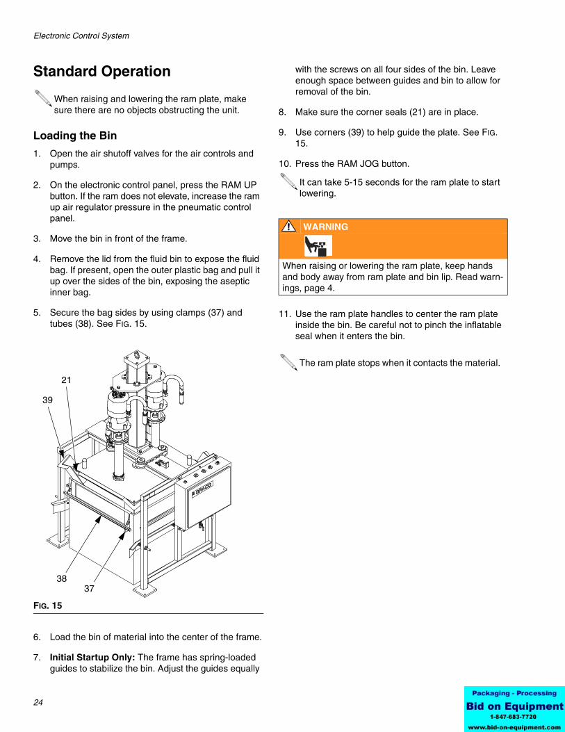
5. Secure the bag sides by using clamps (37) and tubes (38). See FIG. 15.
6. Load the bin of material into the center of the frame.
7. Initial Startup Only: The frame has spring-loaded guides to stabilize the bin. Adjust the guides equally
with the screws on all four sides of the bin. Leave enough space between guides and bin to allow for removal of the bin.
8. Make sure the corner seals (21) are in place.
9. Use corners (39) to help guide the plate. See FIG. 15.
10. Press the RAM JOG button.
11. Use the ram plate handles to center the ram plate inside the bin. Be careful not to pinch the inflatable seal when it enters the bin.
When raising and lowering the ram plate, make sure there are no objects obstructing the unit.
FIG. 15
3837
21
39
It can take 5-15 seconds for the ram plate to start lowering.
WARNING
When raising or lowering the ram plate, keep hands and body away from ram plate and bin lip. Read warn-ings, page 4.
The ram plate stops when it contacts the material.
Electronic Control System
311163K 25
Automatic Evacuation of the Bin
1. On the Operator Interface, select TARGET/ACTUAL RUN screen.
2. Ram plate seal inflates.
3. Ram down air pressure is applied and pumps start in slow mode, then switches to fast mode.
4. When the low limit setting is reached, the pumps switch to slow mode for 2 minutes and then stop.
5. The ram plate seal deflates and the ram is raises.
Unloading the Bin
1. Follow the Pressure Relief Procedure, page 22.
2. Ensure seal is deflated and ram is raised.
3. Unload the bin from the frame.
System ShutdownFollow the Pressure Relief Procedure, page 22.
Depending on the type of material, it may be best to deflate the seal and raise the ram plate out of the mate-rial or keep the ram plate lowered in the bin. Some materials dry and harden when exposed to air. Cover materials when they are not being used.
Press arrow ➜ to select RUN and press ENT.
TARGET 1000 LBS RUNACTUAL 0000 LBS EXIT
Maintenance
26 311163K
Maintenance
Air Motor IcingAir motor icing occurs when moisture in the compressed air collects in the air motor and freezes, causing the motor to stall. If icing occurs with any of the pumps, shut off the air supply to all pumps and allow the ice to thaw.
To minimize icing:
• Reduce the moisture in your compressed air by using an air dryer or filter, which traps water.
• Main air line should slope slightly downward so water collects and can be drained at the end of the line.
• Plumb a drop line from the top of each main air line. Install an automatic drain or drain valve at the bot-tom of each drop.
• Ensure air motor exhaust tube is outside of a refrig-erated area.
Preventive MaintenanceYour system operating conditions determine how often maintenance is required. Record when and what kind of maintenance is needed to create a maintenance sched-ule.
Flushing the System
• The equipment was tested with water. Flush the system before loading material.
• Flush regularly to avoid having material dry and build up and possibly contaminate new material or cause blockages.
• Flush at the lowest pressure possible. Check con-nectors for leaks and tighten them if necessary.
To flush the system:
1. Load a bin containing water, compatible solvent, or cleaning solution that can dissolve the material and clean the system. Follow the procedure for Loading the Bin, page 16 or page 24.
2. Operate the pumps and circulate the cleaning fluid through the system for about 1-2 minutes or until the equipment is clean.
3. Remove the bin of cleaning fluid from the frame. Fol-low the procedure for Unloading the Bin, page 16 or page 25.
4. Operate the pumps at low pressure to remove excess solvent.
5. Follow the Pressure Relief Procedure, page 15 or page 22.
Cleaning Pumps1. Follow the Pressure Relief Procedure, page 15 or
page 22.
2. Remove pumps from plate and frame.
3. See the pump manual for maintenance and service procedures.
CAUTION
Operating the system without all the pumps functioning can damage the system.
Use solvent that is compatible with the equipment wetted parts and the material you will dispense. See Technical Data in your pump manual for wet-ted parts and consult your material supplier.
Maintenance
311163K 27
Cleaning Ram Plate and Seal1. Follow the Pressure Relief Procedure, page 15 or
page 22. Keep the air supply to the ram open.
2. Raise the ram plate.
3. Engage the manual stop.
4. Remove the inflatable seal and corner seals from the ram plate.
5. Clean the seals and ram plate with a compatible cleaning fluid.
6. Apply a generous amount of lubricant to the ram plate channel and seals.
7. Install the inflatable seal and corner seals on the ram plate. Position the inflatable seal so that the seal bottom is angled into the ram plate channel.
WARNING
Never stand or work under the ram plate without engaging the manual stop. See page 13.
Troubleshooting
28 311163K
Troubleshooting
Problem Cause Solution
Ram plate will not raise or lower.
Air pressure to the ram is too low.
Increase RAM UP air pressure.
Ram plate is stuck in bin. 1. Deflate seal. Turn SEAL INFLATE to OFF.
2. Switch to RAM UP position. When it is raised, check for obstructions in bin or quality of seal.
Pump(s) will not operate. Air pressure to the pump(s) is too low.
Increase PUMP air pressure to a minimum of 30 psi (207 kPa, 2.1 bar). Refer to pump manual.
Pumps will not prime or are cavitating.
Ram plate is not in contact with material.
• Check SEAL and RAM DOWN pressures and adjust until you have a quality seal.
• Refer to troubleshooting in pump manual.
Material bag was sucked into pump.
Shut off air to pumps, deflate seal, and raise ram to clear pump intake.
Premature seal wear. SEAL and RAM DOWN air pressures are too high.
Adjust SEAL and RAM DOWN air pressures until you have proper seal and pump operation.
Material leaking past seal. RAM DOWN air pressure is too high.
Reduce RAM DOWN pressure while ensuring pumps are operating properly.
Container bag is not pulled taut or clamped for smooth bin walls.
Pull bag tight and secure in place.
Corner seals are not in place.
Install corner seals.
Too much material left in bottom of bin.
Container bag is bunched up at bottom of bin
Reduce seal pressure while ensuring there is still a good seal.
Service
311163K 29
Service
Before Servicing
1. Remove the bin from the frame.
2. Follow the Pressure Relief Procedure, page 15 or page 22.
3. Lower the ram plate and deflate the seal.
4. Shut off the air supply to the system.
Replacing Cylinder Bearing (All Models)
See FIG. 16.
1. Follow the Before Servicing procedure, page 29.
2. Remove screws (409) and washers (410), then take cylinder guide bearings (408) off the air motor mounting plate (402).
3. Install cylinder guide bearings (408) on top of the air motor mounting plate (402), using screws (409) and washers (410).
4. Repeat steps 2-3 as needed to replace additional cylinder bearings.
5. Raise and lower the ram plate to check the bear-ings.
See FIG. 16. All models do not use the same parts. Refer to parts drawing for your model.
WARNING
Never stand or work under the ram plate without engaging the manual stop. See page 13.
WARNING
Read warnings, page 3, and follow the Pressure Relief Procedure whenever you:• are instructed to relieve pressure• stop operation• check, clean, or service any of the equipment
CAUTIONTo avoid damaging equipment, replace each bearing individually. Do not remove all four bearings at the same time.
The open arch in the cylinder guide bearings (408) fits around tie rods on the air cylinder (4).
Service
30 311163K
Replacing Ram Plate Seal or Corner Seals (All Models)See FIG. 16.
1. Follow the Before Servicing procedure, page 29.
2. If you are only replacing the corner seals (21) and not the ram plate seal (501, remove the rivet (22) and replace each corner seal individually. Do not remove all 4 corner seals at the same time or the ram plate seal may move out of place. Be care-ful not to puncture the ram plate seal. Skip to step 8.
If you are replacing the ram plate seal (501), remove the rivets (22), then remove all 4 corner seals (21). Check the corner seals for damage and replace if necessary.
3. Disconnect the tube fitting (29) from the seal air supply tube (14).
4. Remove the ram plate seal (501), using a blunt-end tool to avoid damaging the seal. Carefully disen-gage the air stem from the hole in the ram plate (502).
5. Insert the air stem of the new seal (501) into the ram plate (502) hole. To avoid puncturing the new seal, carefully slide the seal in place around the ram plate.
6. Install the four corner seals (21) with rivets (22).
7. Connect the air supply tube (14) to the tube fitting (29).
8. Check operation by inflating and deflating the seal. Check for air leaks. After loading a bin of material into the frame, check whether material leaks around the ram plate and seals.
FIG. 16: Repair (BES1P1 Shown)
21
502
501
29
4
408,409,410
402
Service
311163K 31
Replacing Proximity Switch (Electronic Control Models Only)See FIG. 17.
1. Follow the Before Servicing procedure, page 29.
2. Mark the proximity switch (641) position on its bracket (B) to ensure the new switch is installed the same. Refer to FIG. 17.
3. Disconnect the cable from the switch (641).
4. Remove the two screws, lock washers, and the switch.
5. Secure the new switch to the bracket (B) with the screws and lock washers.
6. Reconnect the cable.
7. Restart the system and verify the switch operates correctly.
Electronic Control Panel Service (Electronic Control Models Only)
Follow the Before Servicing procedure, page 29. Con-sult a qualified electrician to service the control panel.
Recommend 1/4 in. (6.35 mm) space between switch and plate (15).
FIG. 17: Proximity Switch
4
641
15
B
WARNING
Read warnings, page 3.
BES 300 Matrix
32 311163K
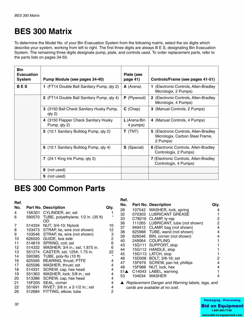
BES 300 MatrixTo determine the Model No. of your Bin Evacuation System from the following matrix, select the six digits which describe your system, working from left to right. The first three digits are always B E S, designating Bin Evacuation System. The remaining three digits designate pump, plate, and controls used. To order replacement parts, refer to the parts lists on pages 34-50.
BES 300 Common Parts
▲ Replacement Danger and Warning labels, tags, and cards are available at no cost.
Bin Evacuation System Pump Module (see pages 34-40)
Plate (see page 41) Controls/Frame (see pages 41-51)
B E S 1 (FT14 Double Ball Sanitary Pump, qty 2) A (Arena) 1 (Electronic Controls, Allen-Bradley Micrologix, 2 Pumps)
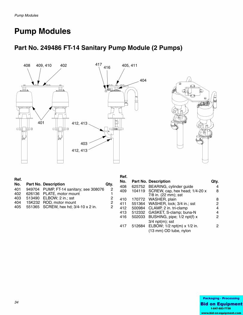
Part No. 249486 FT-14 Sanitary Pump Module (2 Pumps)
401
408 409, 410 402
412, 413
403
412, 413
405, 411
404
417416
Ref. No. Part No. Description Qty.401 949704 PUMP, FT-14 sanitary; see 308076 2402 626136 PLATE, motor mount 1403 513490 ELBOW; 2 in.; sst 2404 15K232 ROD, motor mount 2405 551365 SCREW, hex hd; 3/4-10 x 2 in. 2
417 512684 ELBOW; 1/2 npt(m) x 1/2 in. (13 mm) OD tube, nylon
2
Ref. No. Part No. Description Qty.
Pump Modules
311163K 35
Part No. 249487 FT-14 Sanitary Pump Module (4 Pumps)
401
408 409, 410 402
412, 413
403
412, 413
405, 411
404
417416
Ref. No. Part No. Description Qty.401 949704 PUMP, FT-14 sanitary; see 308076 4402 626656 PLATE, motor mount 1403 513490 ELBOW; 2 in.; sst 4404 15K232 ROD, motor mount 4405 551365 SCREW, hex hd; 3/4-10 x 2 in. 4
417 512684 ELBOW; 1/2 npt(m) x 1/2 in. (13 mm) OD tube, nylon
4
418 514887 ADAPTER, tri-clamp 4
Ref. No. Part No. Description Qty.
Pump Modules
40 311163K
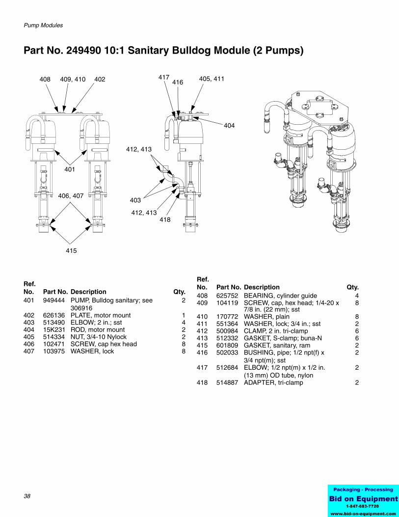
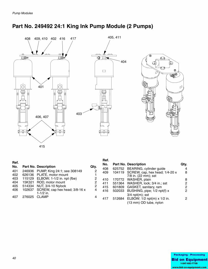
Part No. 249492 24:1 King Ink Pump Module (2 Pumps)
401
406, 407
408 409, 410 402
403
405, 411
404
415
417416
Ref. No. Part No. Description Qty.401 246936 PUMP, King 24:1; see 308149 2402 626136 PLATE, motor mount 1403 115129 ELBOW; 1-1/2 in. npt (fbe) 2404 15K321 ROD, motor mount 2405 514334 NUT, 3/4-10 Nylock 2406 102637 SCREW, cap hex head; 3/8-16 x
BES1P6, BES2P2, BES3P1, BES5A1, BES6L2, BES6T2, and BES7A5 only
1
Controls/Frame
42 311163K
Part No. 15E523, 2 Pump Manual Control Panel
† Not shown
1
AIR IN
PUMP 1
PUMP 2RAM UP
RAM DOWN
21
20
Ref. No. Part No. Description Qty.1 ENCLOSURE, with back panel 12 15E562 LABEL 13† 15E563 LABEL, instructions 14† 512896 REGULATOR 45† GAUGE, 160 PSI 46† VALVE, check 3/8 in. 27† VALVE, air pilot, 3 position 18† VALVE, air pilot operated 19† SWITCH, 3 position 110† REGULATOR 111† VALVE, air pilot operated 1
12† SWITCH, pneumatic, 2 position 213† FITTING, bulkhead, 3/4 in. NPT 114† FITTING, bulkhead, 3/8 in. tube 115† FITTING, bulkhead, 1/2 in. tube 216† MUFFLER, 1/2 in. NPT 217† TUBE, 1/2 in. O.D. AR18† TIUBE, 3/8 in. O.D. AR19† TUBE, 5/32 in. O.D. AR20 FITTING, nipple, hex 121 VALVE, ball; sst 1
Ref. No. Part No. Description Qty.
Controls/Frame
311163K 43
Part No. 15E523, 2 Pump Manual Control Panel, Pneumatic Diagram
Controls/Frame
44 311163K
Part No. 15M343, 4 Pump Manual Control Panel
† Not shown
ti12839a
Ref. No. Part No. Description1 ENCLOSURE, control2 SUBPLATE3† REGULATOR, air 1/2 in. ports 4† REGULATOR, air 0-25 psi5† GAUGE, 0-100 psi 6† GAUGE, 0-30 psi 7† SWITCH, 3 position 8† SWITCH, 2 position 9† PUSH BUTTON, momentary10† VALVE, air, 3-way11† BRACKET, switch