PARADOX.COM Programming Guide 32 Zone Wireless Transceiver Security Systems MG5000 V4.5 MG5050 V4.5 4 to 32 Zone Expandable Security Systems SP4000 V4.5 SP5500 V4.5 SP6000 V4.5 SP7000 V4.5 Always Armed, Never Disarmed
Transcript
Programming Guide
32 Zone Wireless Transceiver Security SystemsMG5000 V4.5MG5050 V4.5
4 to 32 Zone Expandable Security SystemsSP4000 V4.5SP5500 V4.5SP6000 V4.5SP7000 V4.5
Always Armed, Never Disarmed
PARADOX.COM
WarrantyFor complete warranty information on this product please refer to the Limited Warranty Statement found on the website www.paradox.com/terms. Your use of the Paradox product signifies your acceptance of all warranty terms and conditions.
Limitations of Alarm Systems: It must be understood that while your Paradox alarm system is highly advanced and secure, it does not offer any guaranteed protection against burglary, fire or other emergency (fire and emergency options are only available on certain Paradox models). This is due to a number of reasons, including by not limited to inadequate or improper installation/positioning, sensor limitations, battery performance, wireless signal interruption, inadequate maintenance or the potential for the system or telephone lines to be compromised or circumvented. As a result, Paradox does not represent that the alarm system will prevent personal injury or property damage, or in all cases provide adequate warning or protection.
Your security system should therefore be considered as one of many tools available to reduce risk and/or damage of burglary, fire or other emergencies, such other tools include but are not limited to insurance coverage, fire prevention and extinguish devices, and sprinkler systems.
We also strongly recommend that you regularly maintain your security systems and stay aware of new and improved Paradox products and developments.
TBR-21: In order to comply with TBR-21, standard force dialing must be enabled.
UL AND ULC WARNINGS This equipment has the capability of being programmed with features not verified for use in UL installations. To stay within UL and ULC standards, the installer should use the following guidelines when configuring the system:
• All components of the system should be UL listed for the intended application.• If used for “Fire” detection, the installer should refer to NFPA Standards #72, Chapter 2. In addition, once installation is complete, the local fire authority must be notified of
the installation.• WARNING: This equipment must be installed and maintained by qualified service personnel only• This equipment must be verified by a qualified technician once every three years.• All keypads must use an anti-tamper switch.• Do not bypass fire zones.• Maximum allowed entry delay is 45 seconds.• Maximum allowed exit delay is 60 seconds.• Minimum 4 minutes for bell cut-off time.• The following features do not comply with UL requirements: Bypass Recall and Auto Trouble Shutdown. • Do not connect the primary indicating device to a relay. The installer must use the bell output.• To comply with UL985, the auxiliary power output should not exceed 200mA. • Do not connect the zone ground terminal with UL Listed products.• The metallic enclosure must be grounded to the cold water pipe.• All outputs are Class 2 or power-limited, except for the battery terminal.The Class 2 and power-limited fire alarm circuits shall be installed using CL3, CL3R, CL3P, or
substitute cable permitted by the National Electrical Code, ANSI/NFPA 70.• EOL resistor part #2011002000• For UL Installations: Universal UB1640W 16.5VAC min 40VA• All outputs are rated from 11.3Vdc to 12.7Vdc• 12Vdc 4Ah rechargeable acid/lead or gel cell backup battery (YUASA model #NP7-12 recommended) for residential use. Use a 7Ah battery to comply with fire
Important System NotesPlease refer to the following module compatibility exceptions to ensure proper system function:
• Wireless keypads can be used with MG/SP systems that include an RTX3 (not compatible with SP4000 systems).• When using a K636 keypad, only partition 1 is available.• The following modules are not compatible with SP4000 systems: K32RF, K37, K32LCD, RPT1.• When using an SP Series panel, all wireless sections and options do not apply unless an RTX3 is used in conjunction with the panel.• When using an SP6000 panel in conjunction with an RTX3, all K32 and K10V/H keypads must be versions 2.0 or higher. • The K35 Fixed LCD keypad module is only compatible with MG/SP panels version 2.3 and higher.
Default Settings: Options which are bold signify the default value:
e.g. Access code length: 6 digits 4 digits (4 digits is the default value)
WARNING: Important information NOTE: Suggestion or reminder Quick Menu (see page 65)
Module Description Maximum number per system
Current Consumption
K32RF, K37 32-Zone Wireless Keypad Modules 8 total Wireless
K10V/HK32 K32LCDK35K636
10 and 32-Zone Hardwired Keypad Module 15 total including ZX8and RTX3
K10V/H: Min. = 44mA / Max. = 72mAK32: Min. = 49mA / Max. = 148mAK32LCD: Min. = 43mA / Max. = 86mAK35: Min. = 30mA / Max. = 70mAK636: Min. = 28mA / Max. = 33mA
Ademco Contact ID Report Codes ...............................39Automatic Report Code List ........................................40Installer Function Keys .................................................41Trouble Display ............................................................42Wireless Repeater Programming (RPT1) ....................43Wireless Keypad Programming (K32RF / K37) ...........45Wireless Siren Programming .......................................46LCD Keypad Labels (K32LCD) ....................................47User Programming .......................................................50Hardware Connections ................................................55Connecting to WinLoad / BabyWare ............................57Updating Firmware Using WinLoad / BabyWare .........57Metal Box Installation ...................................................58Installer Quick Menu ....................................................65Index ............................................................................68
Magellan / Spectra SP 3
Comparison Chart Security Features MG5000 MG5050StayD
Built-in transceiver
Maximum zones 32* 32*On-board zones 2 (4 with ATZ) 5 (10 with ATZ)Expansion zones (ZX8) 24 (3 x ZX8) 24 (3 x ZX8)Keypad zones 15 15Partitions 2 2User Codes 32 32Remote controls 32 32PGMs 16* (2 on-board) 16* (4 on-board)PGM +/- trigger -
* Any of which can be wireless** Optional*** When used with an SP4000 system, the RTX3 only allows for the use of remote controls.† When used with an SP4000 system, the RX1 only allows for the use of one-way remote controls.‡ For compatible BabyWare version, refer to paradox.com.
4 Programming Guide
Specifications
Entering Programming ModeWARNING: StayD Mode must be deactivated in order to enter programming mode. To deactivate StayD, press [OFF] + [MASTER / USER CODE] + [OFF].
1. Press [ENTER].
2. Enter your [INSTALLER CODE] (default: 000000) or [MAINTENANCE CODE] (no default). [ARM] and [STAY] lights flash. To modify codes, see System Codes on page 50.
3. Enter the 3-digit [SECTION] you wish to program ([ARM] and [STAY] lights are ON).
4. Enter required [DATA].
MG5000 / MG5050Power rating 16.5 VAC (50 or 60Hz) minimum 20 VA (40 VA recommended) Aux. power 600 mA typical, 700 mA maximum, fuseless shutdown at 1.1ABattery 12 VDC, 4Ah/7AhBattery charging current 350 mAOn-board zones MG5000: 2
All on-board PGMS are 100mA low-current outputsDimensions SP4000: 14 x 6.6cm (5.5 x 2.6”)
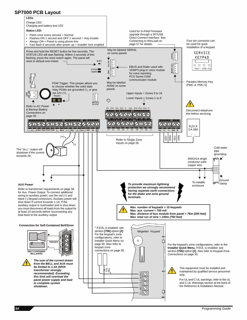
SP5500: 19 x 8.9cm (7.5 x 3.5”) SP6000: 19 x 8.9cm (7.5 x 3.5”) SP7000: 20.3 x 10.8cm (8 x 4.25”)
Operating temperature 0°C to 50°C (32°F to 122°F)
Magellan / Spectra SP 5
Data Entry & Display
Each time the [ENTER] key is pressed, the keypad will display the next digit in the current section and will continue through all the following sections one digit at a time without changing the programmed values. Not available for sections using the Multiple Feature Select Method. Press the [CLEAR] key at any time to exit the Data Display Mode.
There are two methods that can be used to enter data when in programming mode: Single Digit Data Entry and Feature Select Programming methods:
Single Digit Data Entry MethodAfter entering programming mode, some sections will require that you enter decimal values from 000 to 255. Other sections will require that you enter hexadecimal values from 0 to F. The required data will be clearly indicated in this manual. When entering the final digit in a section, the panel will automatically save and advance to the next section. Refer to Decimal and Hexadecimal Values on page 6 to see the keys and their equivalent decimal and/or hexadecimal value.
Feature Select Programming MethodAfter entering certain sections, eight options will be displayed where each option from [1] to [8] represents a specific feature. Press the key corresponding to the desired option. This means the option is ON. Press the key again to remove the digit, thereby, turning OFF the option. Press the [SLEEP] key to set all eight options to OFF. When the options are set, press the [ENTER] key to save and advance to the next section.
Important Settings and Modes
Decimal and Hexadecimal Values
Section Description[950] Reset all programmable sections to factory default values [955] Clear bus module trouble (remove disconnected module from the bus)[960] Wireless transmitter serial number display (press any button on the assigned remote control or press the tamper switch of
the wireless module, then press [ENTER] to view the next digit)[970] Download memory key into panel (see the Reference & Installation Manual)[975] Upload panel into the memory key (see the Reference & Installation Manual)[980] Display version number of the panel (press [ENTER] to view the next digit)
Value or Action What Do I Press?What Do I See?
32-zone LED 10-zone LED
Value 0 / Replace Current Digit with 0
[SLEEP] Erase digit and remain in section Erase digit and remain in section
Values 1 to 9 [1] TO [9] Zone 1 to 9 Keys 1 to 9A (hex only) [0] Zone 10 Key 0(10)B (hex only) [OFF] Zone 11 OFFC (hex only) [BYP] Zone 12 BYPD (hex only) [MEM] Zone 13 MEME (hex only) [TBL] Zone 14 TBLF (hex only) [ ] Zone 15 [ ]
Exit Without Saving [CLEAR] Arm & Stay LED flash Arm & Stay LED flashSave Data (hex only) [ENTER] Advances to the next section Advances to the next section
K636 K10V/H K35/K37 K32RF/K32
To access the Data Display Mode, press the [ENTER] key after entering a section and before entering any data. The four LEDs/Icon as indicated below will begin to flash indicating that you are in the Data Display Mode.
6 Programming Guide
System Codes
Panel ResetPerforming a panel reset will reset all programmable sections to factory default values.
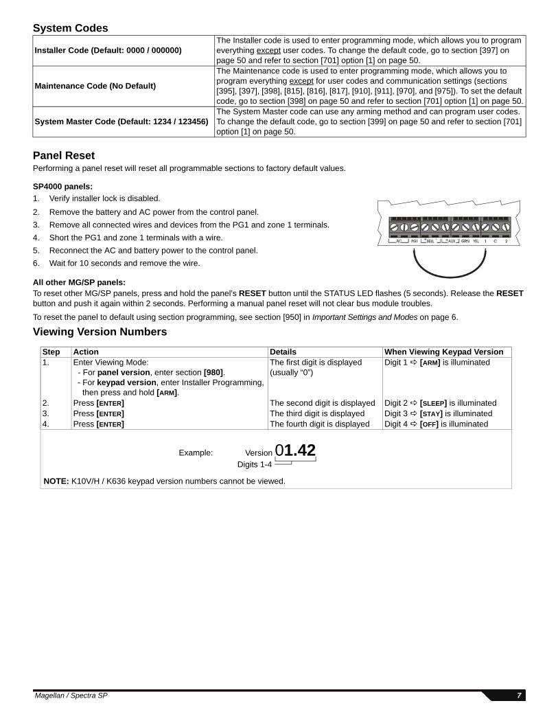
SP4000 panels:
1. Verify installer lock is disabled.
2. Remove the battery and AC power from the control panel.
3. Remove all connected wires and devices from the PG1 and zone 1 terminals.
4. Short the PG1 and zone 1 terminals with a wire.
5. Reconnect the AC and battery power to the control panel.
6. Wait for 10 seconds and remove the wire.
All other MG/SP panels:To reset other MG/SP panels, press and hold the panel’s RESET button until the STATUS LED flashes (5 seconds). Release the RESET button and push it again within 2 seconds. Performing a manual panel reset will not clear bus module troubles.
To reset the panel to default using section programming, see section [950] in Important Settings and Modes on page 6.
Viewing Version Numbers
Installer Code (Default: 0000 / 000000) The Installer code is used to enter programming mode, which allows you to program everything except user codes. To change the default code, go to section [397] on page 50 and refer to section [701] option [1] on page 50.
Maintenance Code (No Default)
The Maintenance code is used to enter programming mode, which allows you to program everything except for user codes and communication settings (sections [395], [397], [398], [815], [816], [817], [910], [911], [970], and [975]). To set the default code, go to section [398] on page 50 and refer to section [701] option [1] on page 50.
System Master Code (Default: 1234 / 123456)The System Master code can use any arming method and can program user codes. To change the default code, go to section [399] on page 50 and refer to section [701] option [1] on page 50.
Example: Version 01.42Digits 1-4
Step Action Details When Viewing Keypad Version1. Enter Viewing Mode:
- For panel version, enter section [980]. - For keypad version, enter Installer Programming, then press and hold [ARM].
The first digit is displayed(usually “0”)
Digit 1 [ARM] is illuminated
2. Press [ENTER] The second digit is displayed Digit 2 [SLEEP] is illuminated3. Press [ENTER] The third digit is displayed Digit 3 [STAY] is illuminated4. Press [ENTER] The fourth digit is displayed Digit 4 [OFF] is illuminated
NOTE: K10V/H / K636 keypad version numbers cannot be viewed.
Magellan / Spectra SP 7
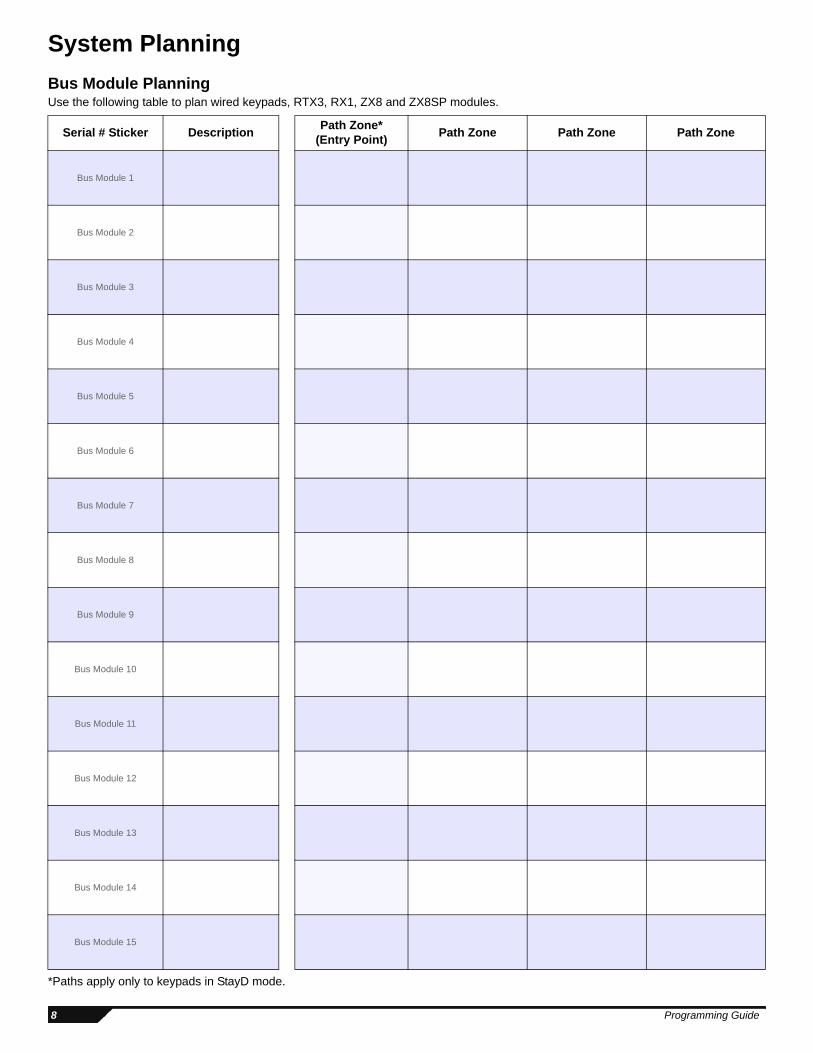
System Planning
Bus Module PlanningUse the following table to plan wired keypads, RTX3, RX1, ZX8 and ZX8SP modules.
*Paths apply only to keypads in StayD mode.
Serial # Sticker DescriptionPath Zone*
(Entry Point)Path Zone Path Zone Path Zone
Bus Module 1
Bus Module 2
Bus Module 3
Bus Module 4
Bus Module 5
Bus Module 6
Bus Module 7
Bus Module 8
Bus Module 9
Bus Module 10
Bus Module 11
Bus Module 12
Bus Module 13
Bus Module 14
Bus Module 15
8 Programming Guide
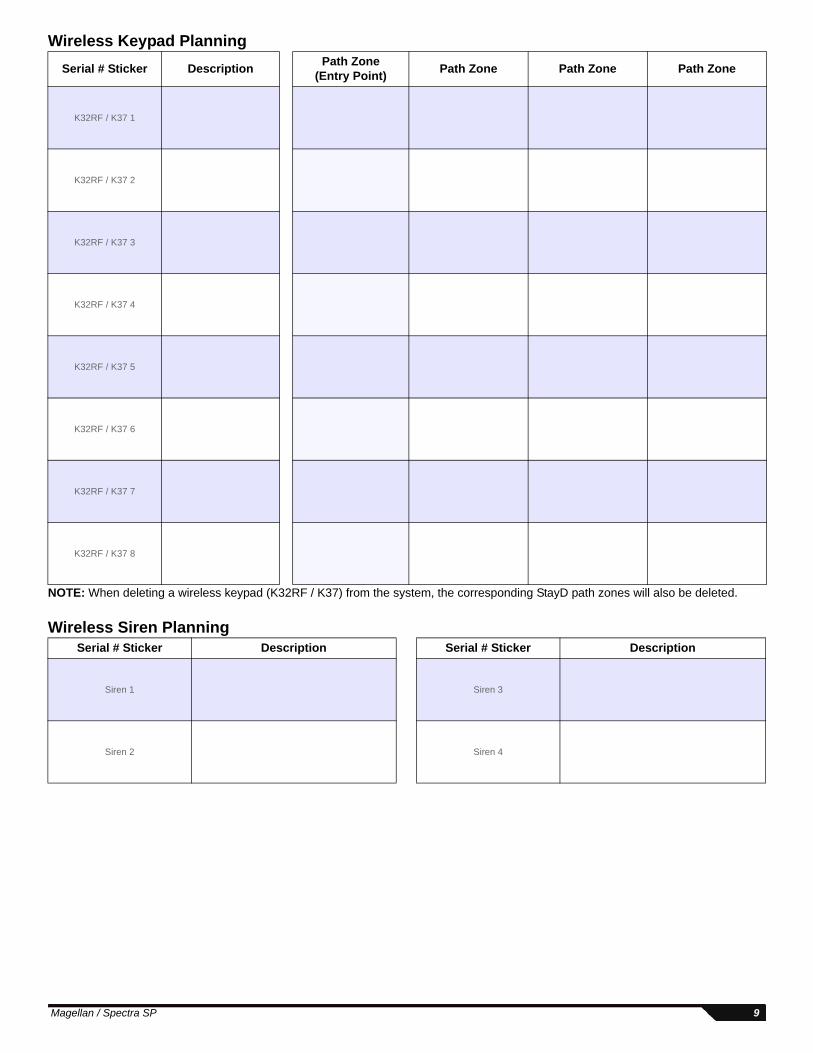
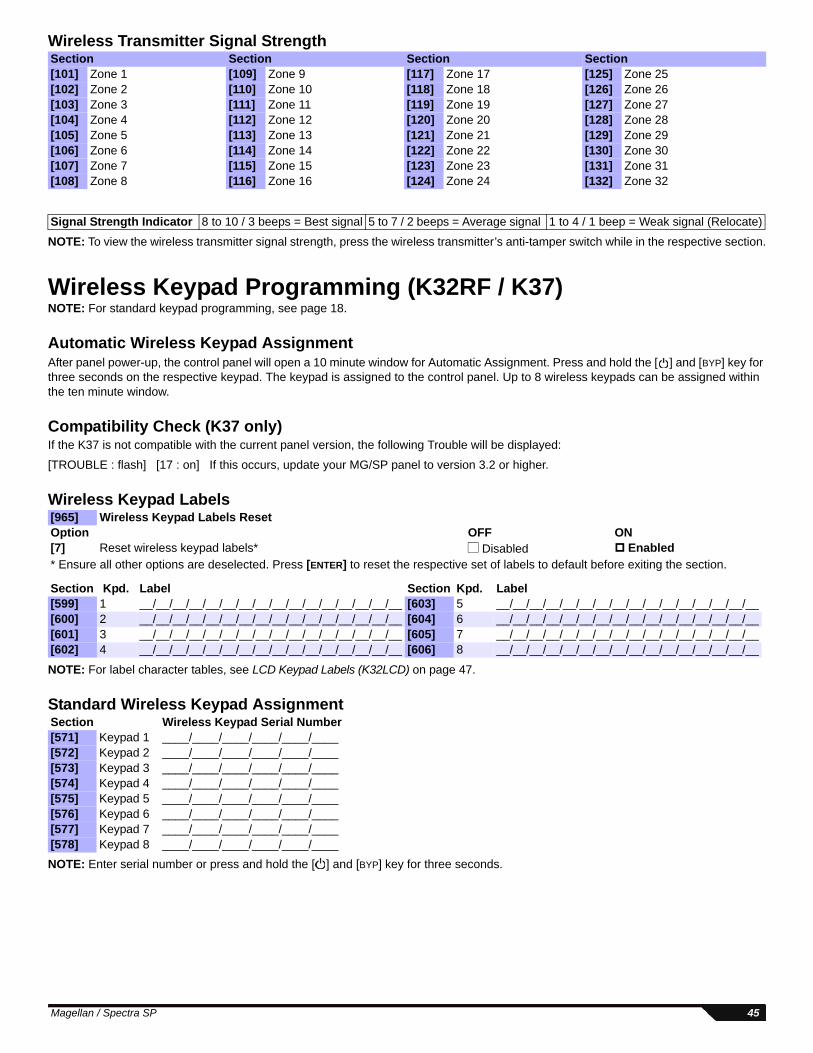
Wireless Keypad Planning
NOTE: When deleting a wireless keypad (K32RF / K37) from the system, the corresponding StayD path zones will also be deleted.
Wireless Siren Planning
Serial # Sticker DescriptionPath Zone
(Entry Point)Path Zone Path Zone Path Zone
K32RF / K37 1
K32RF / K37 2
K32RF / K37 3
K32RF / K37 4
K32RF / K37 5
K32RF / K37 6
K32RF / K37 7
K32RF / K37 8
Serial # Sticker Description Serial # Sticker Description
Siren 1 Siren 3
Siren 2 Siren 4
Magellan / Spectra SP 9
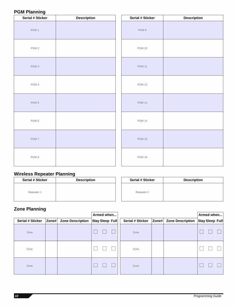
PGM Planning
Wireless Repeater Planning
Zone Planning
Serial # Sticker Description Serial # Sticker Description
PGM 1 PGM 9
PGM 2 PGM 10
PGM 3 PGM 11
PGM 4 PGM 12
PGM 5 PGM 13
PGM 6 PGM 14
PGM 7 PGM 15
PGM 8 PGM 16
Serial # Sticker Description Serial # Sticker Description
Repeater 1 Repeater 2
Armed when... Armed when...
Serial # Sticker Zone# Zone Description Stay Sleep Full Serial # Sticker Zone# Zone Description Stay Sleep Full
Zone Zone
Zone Zone
Zone Zone
10 Programming Guide
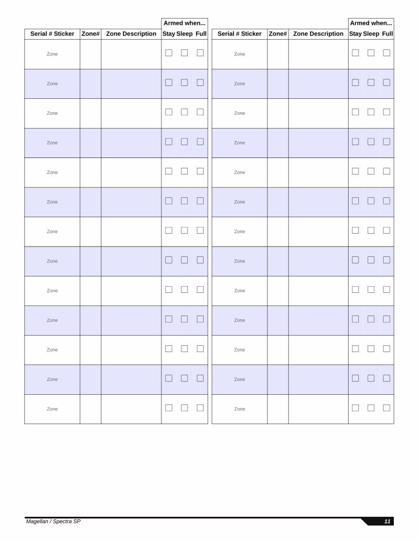
Zone Zone
Zone Zone
Zone Zone
Zone Zone
Zone Zone
Zone Zone
Zone Zone
Zone Zone
Zone Zone
Zone Zone
Zone Zone
Zone Zone
Zone Zone
Armed when... Armed when...
Serial # Sticker Zone# Zone Description Stay Sleep Full Serial # Sticker Zone# Zone Description Stay Sleep Full
Magellan / Spectra SP 11
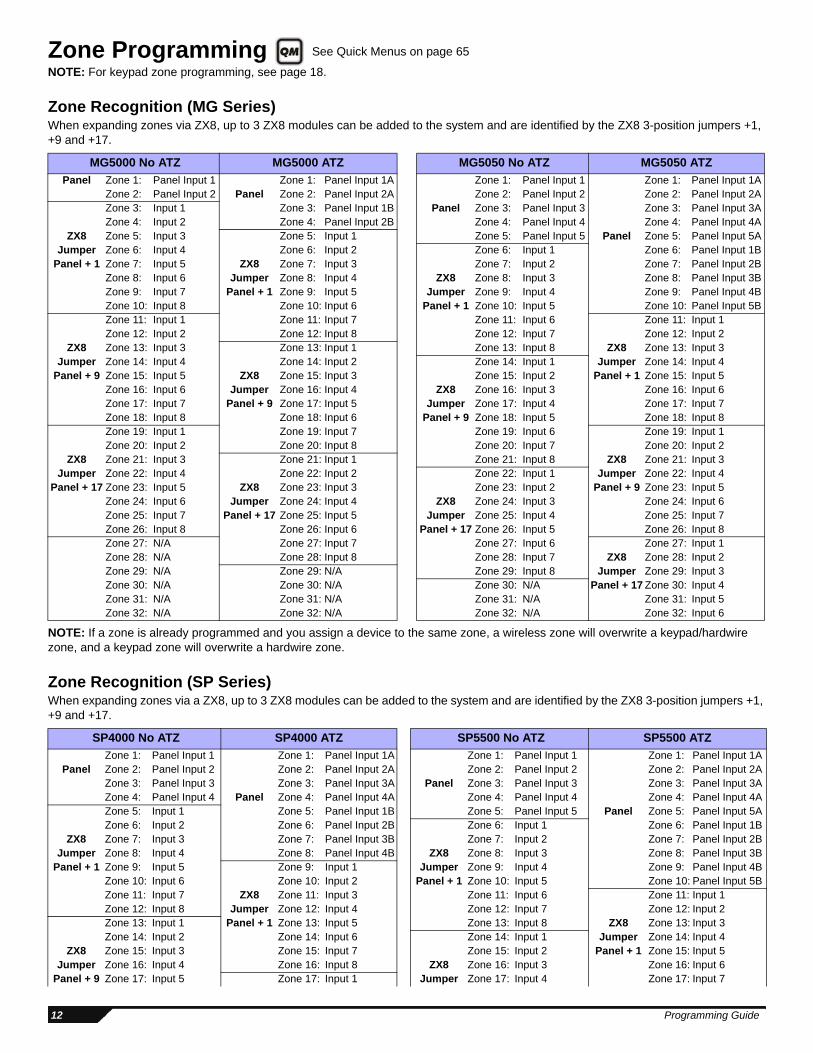
Zone Programming NOTE: For keypad zone programming, see page 18.
Zone Recognition (MG Series)When expanding zones via ZX8, up to 3 ZX8 modules can be added to the system and are identified by the ZX8 3-position jumpers +1, +9 and +17.
NOTE: If a zone is already programmed and you assign a device to the same zone, a wireless zone will overwrite a keypad/hardwire zone, and a keypad zone will overwrite a hardwire zone.
Zone Recognition (SP Series)When expanding zones via a ZX8, up to 3 ZX8 modules can be added to the system and are identified by the ZX8 3-position jumpers +1, +9 and +17.
MG5000 No ATZ MG5000 ATZ MG5050 No ATZ MG5050 ATZ
Panel Zone 1: Panel Input 1 Zone 1: Panel Input 1A Zone 1: Panel Input 1 Zone 1: Panel Input 1AZone 2: Panel Input 2 Panel Zone 2: Panel Input 2A Zone 2: Panel Input 2 Zone 2: Panel Input 2AZone 3: Input 1 Zone 3: Panel Input 1B Panel Zone 3: Panel Input 3 Zone 3: Panel Input 3AZone 4: Input 2 Zone 4: Panel Input 2B Zone 4: Panel Input 4 Zone 4: Panel Input 4A
ZX8 Zone 5: Input 3 Zone 5: Input 1 Zone 5: Panel Input 5 Panel Zone 5: Panel Input 5AJumper Zone 6: Input 4 Zone 6: Input 2 Zone 6: Input 1 Zone 6: Panel Input 1B
Panel + 1 Zone 7: Input 5 ZX8 Zone 7: Input 3 Zone 7: Input 2 Zone 7: Panel Input 2BZone 8: Input 6 Jumper Zone 8: Input 4 ZX8 Zone 8: Input 3 Zone 8: Panel Input 3BZone 9: Input 7 Panel + 1 Zone 9: Input 5 Jumper Zone 9: Input 4 Zone 9: Panel Input 4BZone 10: Input 8 Zone 10: Input 6 Panel + 1 Zone 10: Input 5 Zone 10: Panel Input 5BZone 11: Input 1 Zone 11: Input 7 Zone 11: Input 6 Zone 11: Input 1Zone 12: Input 2 Zone 12: Input 8 Zone 12: Input 7 Zone 12: Input 2
ZX8 Zone 13: Input 3 Zone 13: Input 1 Zone 13: Input 8 ZX8 Zone 13: Input 3Jumper Zone 14: Input 4 Zone 14: Input 2 Zone 14: Input 1 Jumper Zone 14: Input 4
Panel + 9 Zone 15: Input 5 ZX8 Zone 15: Input 3 Zone 15: Input 2 Panel + 1 Zone 15: Input 5Zone 16: Input 6 Jumper Zone 16: Input 4 ZX8 Zone 16: Input 3 Zone 16: Input 6Zone 17: Input 7 Panel + 9 Zone 17: Input 5 Jumper Zone 17: Input 4 Zone 17: Input 7Zone 18: Input 8 Zone 18: Input 6 Panel + 9 Zone 18: Input 5 Zone 18: Input 8Zone 19: Input 1 Zone 19: Input 7 Zone 19: Input 6 Zone 19: Input 1Zone 20: Input 2 Zone 20: Input 8 Zone 20: Input 7 Zone 20: Input 2
ZX8 Zone 21: Input 3 Zone 21: Input 1 Zone 21: Input 8 ZX8 Zone 21: Input 3Jumper Zone 22: Input 4 Zone 22: Input 2 Zone 22: Input 1 Jumper Zone 22: Input 4
Panel + 17 Zone 23: Input 5 ZX8 Zone 23: Input 3 Zone 23: Input 2 Panel + 9 Zone 23: Input 5Zone 24: Input 6 Jumper Zone 24: Input 4 ZX8 Zone 24: Input 3 Zone 24: Input 6Zone 25: Input 7 Panel + 17 Zone 25: Input 5 Jumper Zone 25: Input 4 Zone 25: Input 7Zone 26: Input 8 Zone 26: Input 6 Panel + 17 Zone 26: Input 5 Zone 26: Input 8Zone 27: N/A Zone 27: Input 7 Zone 27: Input 6 Zone 27: Input 1Zone 28: N/A Zone 28: Input 8 Zone 28: Input 7 ZX8 Zone 28: Input 2Zone 29: N/A Zone 29: N/A Zone 29: Input 8 Jumper Zone 29: Input 3Zone 30: N/A Zone 30: N/A Zone 30: N/A Panel + 17 Zone 30: Input 4Zone 31: N/A Zone 31: N/A Zone 31: N/A Zone 31: Input 5Zone 32: N/A Zone 32: N/A Zone 32: N/A Zone 32: Input 6
SP4000 No ATZ SP4000 ATZ SP5500 No ATZ SP5500 ATZ
Zone 1: Panel Input 1 Zone 1: Panel Input 1A Zone 1: Panel Input 1 Zone 1: Panel Input 1APanel Zone 2: Panel Input 2 Zone 2: Panel Input 2A Zone 2: Panel Input 2 Zone 2: Panel Input 2A
Zone 3: Panel Input 3 Zone 3: Panel Input 3A Panel Zone 3: Panel Input 3 Zone 3: Panel Input 3AZone 4: Panel Input 4 Panel Zone 4: Panel Input 4A Zone 4: Panel Input 4 Zone 4: Panel Input 4AZone 5: Input 1 Zone 5: Panel Input 1B Zone 5: Panel Input 5 Panel Zone 5: Panel Input 5AZone 6: Input 2 Zone 6: Panel Input 2B Zone 6: Input 1 Zone 6: Panel Input 1B
ZX8 Zone 7: Input 3 Zone 7: Panel Input 3B Zone 7: Input 2 Zone 7: Panel Input 2BJumper Zone 8: Input 4 Zone 8: Panel Input 4B ZX8 Zone 8: Input 3 Zone 8: Panel Input 3B
Panel + 1 Zone 9: Input 5 Zone 9: Input 1 Jumper Zone 9: Input 4 Zone 9: Panel Input 4BZone 10: Input 6 Zone 10: Input 2 Panel + 1 Zone 10: Input 5 Zone 10: Panel Input 5BZone 11: Input 7 ZX8 Zone 11: Input 3 Zone 11: Input 6 Zone 11: Input 1Zone 12: Input 8 Jumper Zone 12: Input 4 Zone 12: Input 7 Zone 12: Input 2Zone 13: Input 1 Panel + 1 Zone 13: Input 5 Zone 13: Input 8 ZX8 Zone 13: Input 3Zone 14: Input 2 Zone 14: Input 6 Zone 14: Input 1 Jumper Zone 14: Input 4
ZX8 Zone 15: Input 3 Zone 15: Input 7 Zone 15: Input 2 Panel + 1 Zone 15: Input 5Jumper Zone 16: Input 4 Zone 16: Input 8 ZX8 Zone 16: Input 3 Zone 16: Input 6
Panel + 9 Zone 17: Input 5 Zone 17: Input 1 Jumper Zone 17: Input 4 Zone 17: Input 7
See Quick Menus on page 65
12 Programming Guide
NOTE: If a zone is already programmed and you assign a device to the same zone, a wireless zone will overwrite a keypad/hardwire zone, and a keypad zone will overwrite a hardwire zone.
Zone 18: Input 6 Zone 18: Input 2 Panel + 9 Zone 18: Input 5 Zone 18: Input 8Zone 19: Input 7 ZX8 Zone 19: Input 3 Zone 19: Input 6 Zone 19: Input 1Zone 20: Input 8 Jumper Zone 20: Input 4 Zone 20: Input 7 Zone 20: Input 2Zone 21: Input 1 Panel + 9 Zone 21: Input 5 Zone 21: Input 8 ZX8 Zone 21: Input 3Zone 22: Input 2 Zone 22: Input 6 Zone 22: Input 1 Jumper Zone 22: Input 4
ZX8 Zone 23: Input 3 Zone 23: Input 7 Zone 23: Input 2 Panel + 9 Zone 23: Input 5Jumper Zone 24: Input 4 Zone 24: Input 8 ZX8 Zone 24: Input 3 Zone 24: Input 6
Panel + 17 Zone 25: Input 5 Zone 25: Input 1 Jumper Zone 25: Input 4 Zone 25: Input 7Zone 26: Input 6 Zone 26: Input 2 Panel + 17 Zone 26: Input 5 Zone 26: Input 8Zone 27: Input 7 ZX8 Zone 27: Input 3 Zone 27: Input 6 Zone 27: Input 1Zone 28: Input 8 Jumper Zone 28: Input 4 Zone 28: Input 7 ZX8 Zone 28: Input 2Zone 29: N/A Panel + 17 Zone 29: Input 5 Zone 29: Input 8 Jumper Zone 29: Input 3Zone 30: N/A Zone 30: Input 6 Zone 30: N/A Panel + 17 Zone 30: Input 4Zone 31: N/A Zone 31: Input 7 Zone 31: N/A Zone 31: Input 5Zone 32: N/A Zone 32: Input 8 Zone 32: N/A Zone 32: Input 6
SP6000 No ATZ SP6000 ATZ SP7000 No ATZ SP7000 ATZ
Zone 1: Panel Input 1 Zone 1: Panel Input 1A Zone 1: Panel Input 1 Zone 1: Panel Input 1AZone 2: Panel Input 2 Zone 2: Panel Input 2A Zone 2: Panel Input 2 Zone 2: Panel Input 2A
Panel Zone 3: Panel Input 3 Zone 3: Panel Input 3A Zone 3: Panel Input 3 Zone 3: Panel Input 3AZone 4: Panel Input 4 Zone 4: Panel Input 4A Zone 4: Panel Input 4 Zone 4: Panel Input 4AZone 5: Panel Input 5 Zone 5: Panel Input 5A Zone 5: Panel Input 5 Zone 5: Panel Input 5AZone 6: Panel Input 6 Zone 6: Panel Input 6A Zone 6: Panel Input 6 Zone 6: Panel Input 6AZone 7: Panel Input 7 Zone 7: Panel Input 7A Zone 7: Panel Input 7 Zone 7: Panel Input 7AZone 8: Panel Input 8 Panel Zone 8: Panel Input 8A Panel Zone 8: Panel Input 8 Zone 8: Panel Input 8AZone 9: Input 1 Zone 9: Panel Input 1B Zone 9: Panel Input 9 Zone 9: Panel Input 9AZone 10: Input 2 Zone 10: Panel Input 2B Zone 10: Panel Input 10 Zone 10: Panel Input 10A
ZX8 Zone 11: Input 3 Zone 11: Panel Input 3B Zone 11: Panel Input 11 Zone 11: Panel Input 11AJumper Zone 12: Input 4 Zone 12: Panel Input 4B Zone 12: Panel Input 12 Zone 12: Panel Input 12A
Panel + 1 Zone 13: Input 5 Zone 13: Panel Input 5B Zone 13: Panel Input 13 Zone 13: Panel Input 13AZone 14: Input 6 Zone 14: Panel Input 6B Zone 14: Panel Input 14 Zone 14: Panel Input 14AZone 15: Input 7 Zone 15: Panel Input 7B Zone 15: Panel Input 15 Zone 15: Panel Input 15AZone 16: Input 8 Zone 16: Panel Input 8B Zone 16: Panel Input 16 Panel Zone 16: Panel Input 16AZone 17: Input 1 Zone 17: Input 1 Zone 17: Input 1 Zone 17: Panel Input 1BZone 18: Input 2 Zone 18: Input 2 Zone 18: Input 2 Zone 18: Panel Input 2B
ZX8 Zone 19: Input 3 ZX8 Zone 19: Input 3 ZX8 Zone 19: Input 3 Zone 19: Panel Input 3BJumper Zone 20: Input 4 Jumper Zone 20: Input 4 Jumper Zone 20: Input 4 Zone 20: Panel Input 4B
Panel + 9 Zone 21: Input 5 Panel + 1 Zone 21: Input 5 Panel + 1 Zone 21: Input 5 Zone 21: Panel Input 5BZone 22: Input 6 Zone 22: Input 6 Zone 22: Input 6 Zone 22: Panel Input 6BZone 23: Input 7 Zone 23: Input 7 Zone 23: Input 7 Zone 23: Panel Input 7BZone 24: Input 8 Zone 24: Input 8 Zone 24: Input 8 Zone 24: Panel Input 8BZone 25: Input 1 Zone 25: Input 1 Zone 25: Input 1 Zone 25: Panel Input 9BZone 26: Input 2 Zone 26: Input 2 Zone 26: Input 2 Zone 26: Panel Input 10B
ZX8 Zone 27: Input 3 ZX8 Zone 27: Input 3 ZX8 Zone 27: Input 3 Zone 27: Panel Input 11BJumper Zone 28: Input 4 Jumper Zone 28: Input 4 Jumper Zone 28: Input 4 Zone 28: Panel Input 12B
Panel + 17 Zone 29: Input 5 Panel + 9 Zone 29: Input 5 Panel + 9 Zone 29: Input 5 Zone 29: Panel Input 13BZone 30: Input 6 Zone 30: Input 6 Zone 30: Input 6 Zone 30: Panel Input 14BZone 31: Input 7 Zone 31: Input 7 Zone 31: Input 7 Zone 31: Panel Input 15BZone 32: Input 8 Zone 32: Input 8 Zone 32: Input 8 Zone 32: Panel Input 16B
SP4000 No ATZ SP4000 ATZ SP5500 No ATZ SP5500 ATZ
Magellan / Spectra SP 13
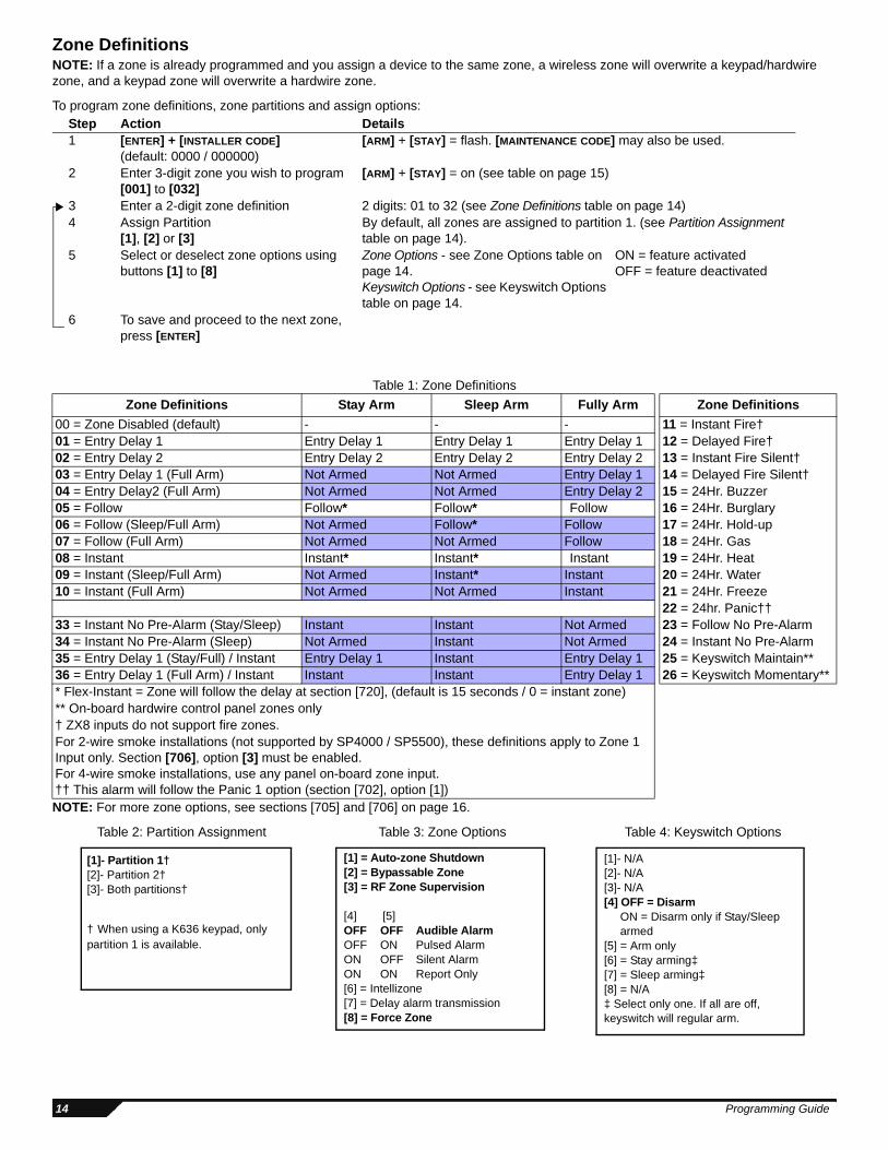
Zone DefinitionsNOTE: If a zone is already programmed and you assign a device to the same zone, a wireless zone will overwrite a keypad/hardwire zone, and a keypad zone will overwrite a hardwire zone.
To program zone definitions, zone partitions and assign options:
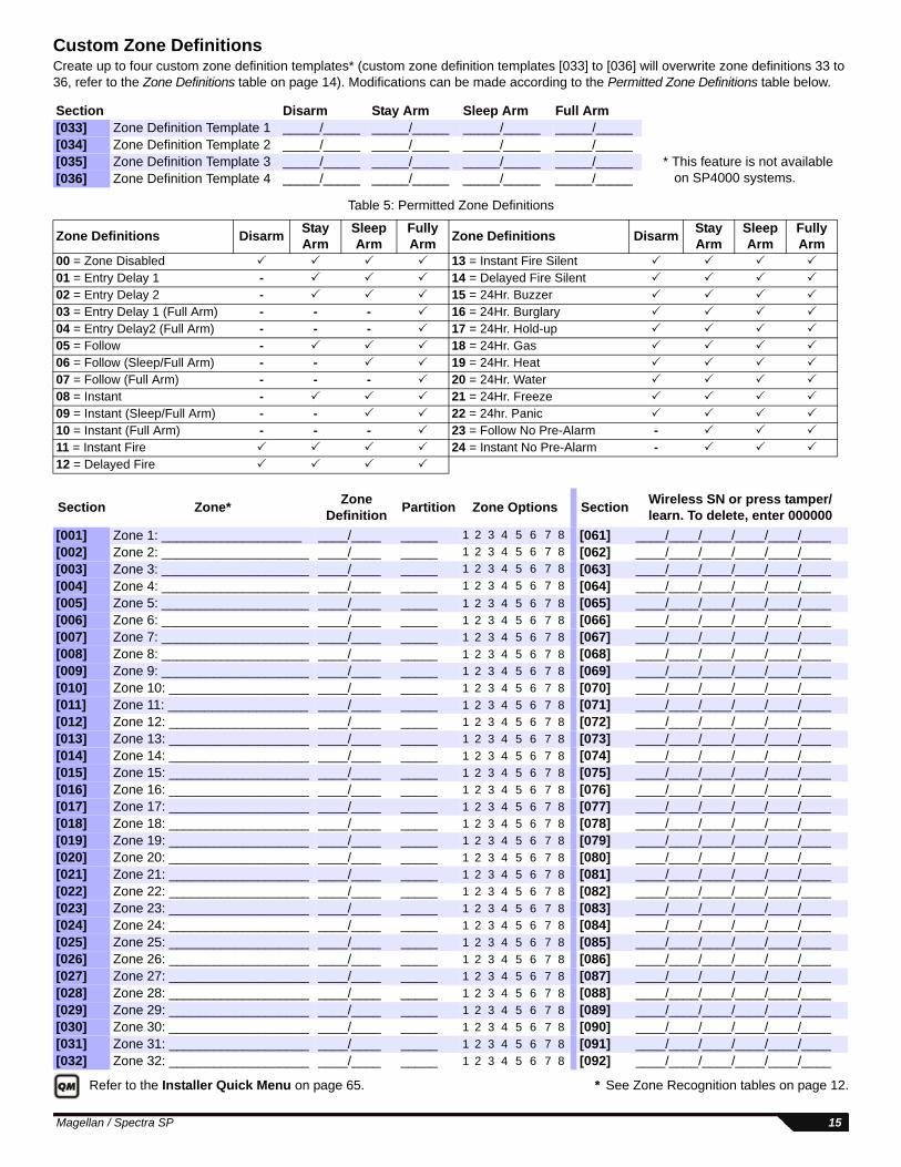
Table 1: Zone Definitions
NOTE: For more zone options, see sections [705] and [706] on page 16.
Step Action Details1 [ENTER] + [INSTALLER CODE]
(default: 0000 / 000000)[ARM] + [STAY] = flash. [MAINTENANCE CODE] may also be used.
2 Enter 3-digit zone you wish to program[001] to [032]
[ARM] + [STAY] = on (see table on page 15)
3 Enter a 2-digit zone definition 2 digits: 01 to 32 (see Zone Definitions table on page 14)4 Assign Partition
[1], [2] or [3]By default, all zones are assigned to partition 1. (see Partition Assignment table on page 14).
5 Select or deselect zone options using buttons [1] to [8]
Zone Options - see Zone Options table on page 14.Keyswitch Options - see Keyswitch Options table on page 14.
ON = feature activatedOFF = feature deactivated
6 To save and proceed to the next zone, press [ENTER]
Zone Definitions Stay Arm Sleep Arm Fully Arm Zone Definitions
22 = 24hr. Panic††33 = Instant No Pre-Alarm (Stay/Sleep) Instant Instant Not Armed 23 = Follow No Pre-Alarm34 = Instant No Pre-Alarm (Sleep) Not Armed Instant Not Armed 24 = Instant No Pre-Alarm35 = Entry Delay 1 (Stay/Full) / Instant Entry Delay 1 Instant Entry Delay 1 25 = Keyswitch Maintain**36 = Entry Delay 1 (Full Arm) / Instant Instant Instant Entry Delay 1 26 = Keyswitch Momentary*** Flex-Instant = Zone will follow the delay at section [720], (default is 15 seconds / 0 = instant zone)** On-board hardwire control panel zones only† ZX8 inputs do not support fire zones. For 2-wire smoke installations (not supported by SP4000 / SP5500), these definitions apply to Zone 1 Input only. Section [706], option [3] must be enabled.For 4-wire smoke installations, use any panel on-board zone input.†† This alarm will follow the Panic 1 option (section [702], option [1])
[1]- N/A[2]- N/A[3]- N/A[4] OFF = Disarm ON = Disarm only if Stay/Sleep armed[5] = Arm only[6] = Stay arming‡[7] = Sleep arming‡[8] = N/A‡ Select only one. If all are off, keyswitch will regular arm.
[1] = Auto-zone Shutdown [2] = Bypassable Zone [3] = RF Zone Supervision
[4] [5]OFF OFF Audible AlarmOFF ON Pulsed AlarmON OFF Silent AlarmON ON Report Only[6] = Intellizone[7] = Delay alarm transmission[8] = Force Zone
[1]- Partition 1†[2]- Partition 2†[3]- Both partitions†
† When using a K636 keypad, only partition 1 is available.
Custom Zone DefinitionsCreate up to four custom zone definition templates* (custom zone definition templates [033] to [036] will overwrite zone definitions 33 to 36, refer to the Zone Definitions table on page 14). Modifications can be made according to the Permitted Zone Definitions table below.
Table 5: Permitted Zone Definitions
Refer to the Installer Quick Menu on page 65. * See Zone Recognition tables on page 12.
Section Disarm Stay Arm Sleep Arm Full Arm[033] Zone Definition Template 1 _____/_____ _____/_____ _____/_____ _____/_____[034] Zone Definition Template 2 _____/_____ _____/_____ _____/_____ _____/_____[035] Zone Definition Template 3 _____/_____ _____/_____ _____/_____ _____/_____ * This feature is not available
on SP4000 systems.[036] Zone Definition Template 4 _____/_____ _____/_____ _____/_____ _____/_____
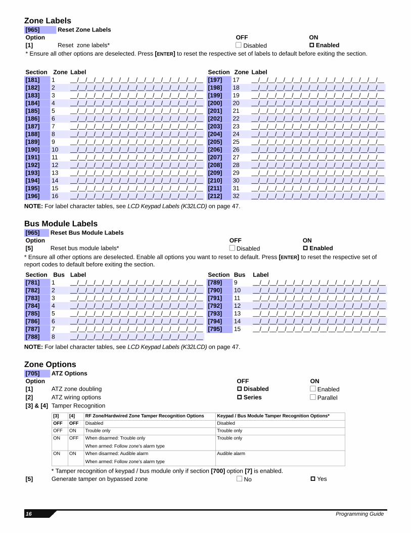
NOTE: For label character tables, see LCD Keypad Labels (K32LCD) on page 47.
Bus Module Labels
* Ensure all other options are deselected. Enable all options you want to reset to default. Press [ENTER] to reset the respective set of report codes to default before exiting the section.
NOTE: For label character tables, see LCD Keypad Labels (K32LCD) on page 47.
Zone Options
[965] Reset Zone LabelsOption OFF ON[1] Reset zone labels* Disabled Enabled* Ensure all other options are deselected. Press [ENTER] to reset the respective set of labels to default before exiting the section.
[705] ATZ OptionsOption OFF ON[1] ATZ zone doubling Disabled Enabled[2] ATZ wiring options Series Parallel[3] & [4] Tamper Recognition
[5] Generate tamper on bypassed zone No Yes
[3] [4] RF Zone/Hardwired Zone Tamper Recognition Options Keypad / Bus Module Tamper Recognition Options*
OFF OFF Disabled Disabled
OFF ON Trouble only Trouble only
ON OFF When disarmed: Trouble only
When armed: Follow zone’s alarm type
Trouble only
ON ON When disarmed: Audible alarm
When armed: Follow zone’s alarm type
Audible alarm
* Tamper recognition of keypad / bus module only if section [700] option [7] is enabled.
16 Programming Guide
*This option applies to all hardwired zones (panel, keypad, ZX8)
Zone Timers (MG Series)Note that When both ATZ and EOL are enabled, zone speed should not be set below 300ms.
Zone Timers (SP Series)NOTE: When both ATZ and EOL are enabled, zone speed should not be set below 300ms.
[6] & [7] Supervision Options
[8] Generate supervision on bypassed zone No Yes
[706] General Zone Options Option OFF ON[1] Check-in supervision time (except SP4000) 24 hours 80 minutes[2] EOL resistors* Disabled Enabled[3] Zone Input 1 becomes a 2-wire smoke input (except SP5500/SP4000) Disabled Enabled[4] ZX8 ID A (Panel + 1) Input 1 Zone input Tamper input[5] ZX8 ID B (Panel + 9) Input 1 Zone input Tamper input[6] ZX8 ID C (Panel + 17) Input 1 Zone input Tamper input
Section MG5000 MG5050 Data Description (Default 060)[041] Zone 1 (Z1) (Z1) ____/____/____ (000 to 255) x 10ms Hardwire Zone 1 Speed [042] Zone 2 (Z2) (Z2) ____/____/____ (000 to 255) x 10ms Hardwire Zone 2 Speed[043] Zone 3 (Z1 ATZ) (Z3) ____/____/____ (000 to 255) x 10ms Hardwire Zone 3 Speed [044] Zone 4 (Z2 ATZ) (Z4) ____/____/____ (000 to 255) x 10ms Hardwire Zone 4 Speed [045] Zone 5 (Z5) ____/____/____ (000 to 255) x 10ms Hardwire Zone 5 Speed [046] Zone 6 (Z1 ATZ) ____/____/____ (000 to 255) x 10ms Hardwire Zone 6 Speed[047] Zone 7 (Z2 ATZ) ____/____/____ (000 to 255) x 10ms Hardwire Zone 7 Speed [048] Zone 8 (Z3 ATZ) ____/____/____ (000 to 255) x 10ms Hardwire Zone 8 Speed [049] Zone 9 (Z4 ATZ) ____/____/____ (000 to 255) x 10ms Hardwire Zone 9 Speed[050] Zone 10 (Z5 ATZ) ____/____/____ (000 to 255) x 10ms Hardwire Zone 10 Speed [051] Zone 11 ____/____/____ (000 to 255) x 10ms Hardwire Zone 11 Speed [052] Zone 12 ____/____/____ (000 to 255) x 10ms Hardwire Zone 12 Speed [053] Zone 13 ____/____/____ (000 to 255) x 10ms Hardwire Zone 13 Speed [054] Zone 14 ____/____/____ (000 to 255) x 10ms Hardwire Zone 14 Speed [055] Zone 15 ____/____/____ (000 to 255) x 10ms Hardwire Zone 15 Speed [056] Zone 16 ____/____/____ (000 to 255) x 10ms Hardwire Zone 16 Speed
Section SP4000 SP5500 SP6000 SP7000* Data Description (Default 060)[041] Zone 1 (Z1) (Z1) (Z1) (Z1) ____/____/____ (000 to 255) x 10ms Hardwire Zone 1 Speed [042] Zone 2 (Z2) (Z2) (Z2) (Z2) ____/____/____ (000 to 255) x 10ms Hardwire Zone 2 Speed[043] Zone 3 (Z3) (Z3) (Z3) (Z3) ____/____/____ (000 to 255) x 10ms Hardwire Zone 3 Speed [044] Zone 4 (Z4) (Z4) (Z4) (Z4) ____/____/____ (000 to 255) x 10ms Hardwire Zone 4 Speed [045] Zone 5 (Z1 ATZ) (Z5) (Z5) (Z5) ____/____/____ (000 to 255) x 10ms Hardwire Zone 5 Speed [046] Zone 6 (Z2 ATZ) (Z1 ATZ) (Z6) (Z6) ____/____/____ (000 to 255) x 10ms Hardwire Zone 6 Speed[047] Zone 7 (Z3 ATZ) (Z2 ATZ) (Z7) (Z7) ____/____/____ (000 to 255) x 10ms Hardwire Zone 7 Speed [048] Zone 8 (Z4 ATZ) (Z3 ATZ) (Z8) (Z8) ____/____/____ (000 to 255) x 10ms Hardwire Zone 8 Speed [049] Zone 9 (Z4 ATZ) (Z1 ATZ) (Z9) ____/____/____ (000 to 255) x 10ms Hardwire Zone 9 Speed[050] Zone 10 (Z5 ATZ) (Z2 ATZ) (Z10) ____/____/____ (000 to 255) x 10ms Hardwire Zone 10 Speed [051] Zone 11 (Z3 ATZ) (Z11) ____/____/____ (000 to 255) x 10ms Hardwire Zone 11 Speed [052] Zone 12 (Z4 ATZ) (Z12) ____/____/____ (000 to 255) x 10ms Hardwire Zone 12 Speed [053] Zone 13 (Z5 ATZ) (Z13) ____/____/____ (000 to 255) x 10ms Hardwire Zone 13 Speed [054] Zone 14 (Z6 ATZ) (Z14) ____/____/____ (000 to 255) x 10ms Hardwire Zone 14 Speed [055] Zone 15 (Z7 ATZ) (Z15) ____/____/____ (000 to 255) x 10ms Hardwire Zone 15 Speed [056] Zone 16 (Z8 ATZ) (Z16) ____/____/____ (000 to 255) x 10ms Hardwire Zone 16 Speed * SP7000: For zones 17-32 (ATZ), the zone timer is set at 0.6 seconds.
[6] [7] RF Zone Supervision Options (except SP4000) Keypad / Bus Module Supervision Options
OFF OFF Disabled Disabled
OFF ON Trouble only Trouble only
ON OFF When disarmed: Trouble only
When armed: Follow zone’s alarm type
Trouble only
ON ON When disarmed: audible alarm
When armed: Follow zone’s alarm type
Trouble only
Magellan / Spectra SP 17
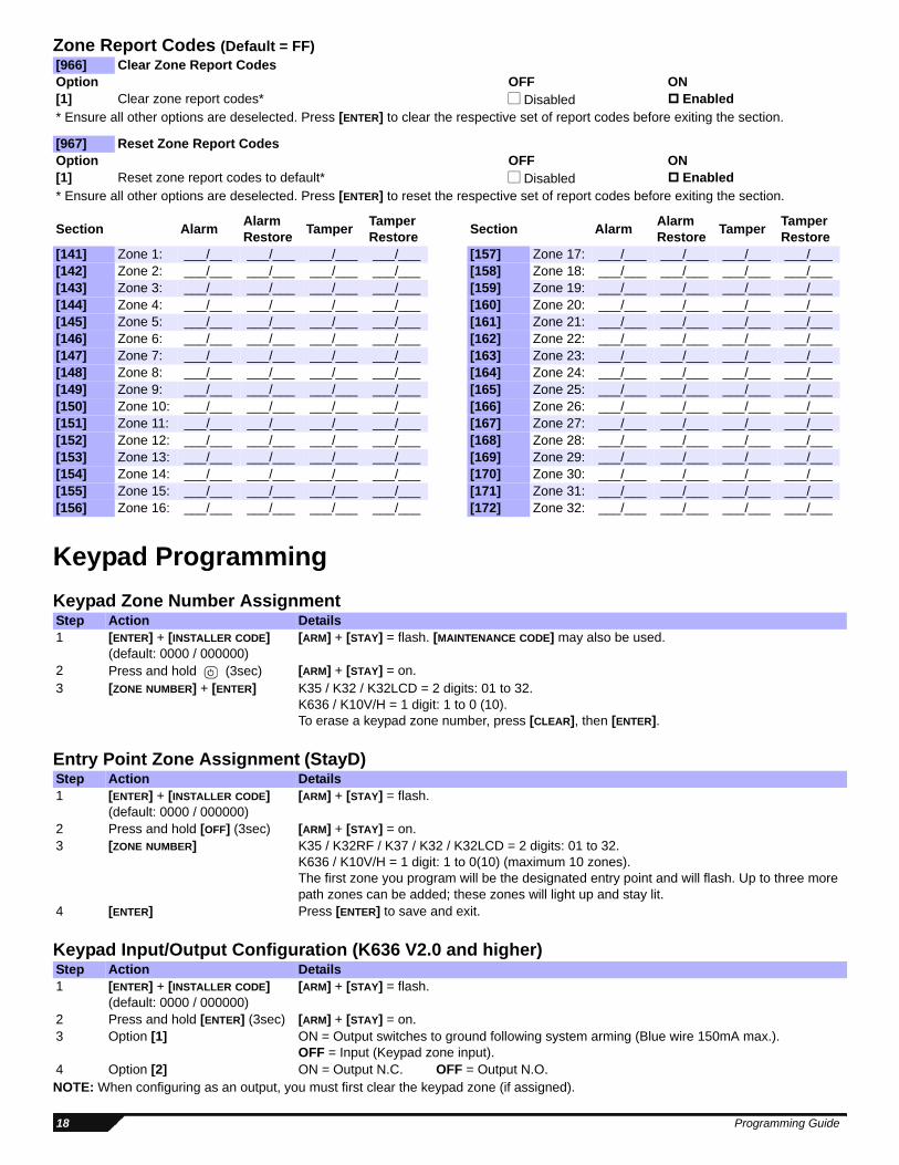
Zone Report Codes (Default = FF)
Keypad Programming
Keypad Zone Number Assignment
Entry Point Zone Assignment (StayD)
Keypad Input/Output Configuration (K636 V2.0 and higher)
NOTE: When configuring as an output, you must first clear the keypad zone (if assigned).
[966] Clear Zone Report CodesOption OFF ON[1] Clear zone report codes* Disabled Enabled* Ensure all other options are deselected. Press [ENTER] to clear the respective set of report codes before exiting the section.
[967] Reset Zone Report CodesOption OFF ON[1] Reset zone report codes to default* Disabled Enabled* Ensure all other options are deselected. Press [ENTER] to reset the respective set of report codes before exiting the section.
Section AlarmAlarm Restore
TamperTamper Restore
Section AlarmAlarm Restore
TamperTamper Restore
[141] Zone 1: ___/___ ___/___ ___/___ ___/___ [157] Zone 17: ___/___ ___/___ ___/___ ___/___[142] Zone 2: ___/___ ___/___ ___/___ ___/___ [158] Zone 18: ___/___ ___/___ ___/___ ___/___[143] Zone 3: ___/___ ___/___ ___/___ ___/___ [159] Zone 19: ___/___ ___/___ ___/___ ___/___[144] Zone 4: ___/___ ___/___ ___/___ ___/___ [160] Zone 20: ___/___ ___/___ ___/___ ___/___[145] Zone 5: ___/___ ___/___ ___/___ ___/___ [161] Zone 21: ___/___ ___/___ ___/___ ___/___[146] Zone 6: ___/___ ___/___ ___/___ ___/___ [162] Zone 22: ___/___ ___/___ ___/___ ___/___[147] Zone 7: ___/___ ___/___ ___/___ ___/___ [163] Zone 23: ___/___ ___/___ ___/___ ___/___[148] Zone 8: ___/___ ___/___ ___/___ ___/___ [164] Zone 24: ___/___ ___/___ ___/___ ___/___[149] Zone 9: ___/___ ___/___ ___/___ ___/___ [165] Zone 25: ___/___ ___/___ ___/___ ___/___[150] Zone 10: ___/___ ___/___ ___/___ ___/___ [166] Zone 26: ___/___ ___/___ ___/___ ___/___[151] Zone 11: ___/___ ___/___ ___/___ ___/___ [167] Zone 27: ___/___ ___/___ ___/___ ___/___[152] Zone 12: ___/___ ___/___ ___/___ ___/___ [168] Zone 28: ___/___ ___/___ ___/___ ___/___[153] Zone 13: ___/___ ___/___ ___/___ ___/___ [169] Zone 29: ___/___ ___/___ ___/___ ___/___[154] Zone 14: ___/___ ___/___ ___/___ ___/___ [170] Zone 30: ___/___ ___/___ ___/___ ___/___[155] Zone 15: ___/___ ___/___ ___/___ ___/___ [171] Zone 31: ___/___ ___/___ ___/___ ___/___[156] Zone 16: ___/___ ___/___ ___/___ ___/___ [172] Zone 32: ___/___ ___/___ ___/___ ___/___
Step Action Details1 [ENTER] + [INSTALLER CODE]
(default: 0000 / 000000)[ARM] + [STAY] = flash. [MAINTENANCE CODE] may also be used.
2 Press and hold (3sec) [ARM] + [STAY] = on.3 [ZONE NUMBER] + [ENTER] K35 / K32 / K32LCD = 2 digits: 01 to 32.
K636 / K10V/H = 1 digit: 1 to 0 (10).To erase a keypad zone number, press [CLEAR], then [ENTER].
Step Action Details1 [ENTER] + [INSTALLER CODE]
(default: 0000 / 000000)[ARM] + [STAY] = flash.
2 Press and hold [OFF] (3sec) [ARM] + [STAY] = on.3 [ZONE NUMBER] K35 / K32RF / K37 / K32 / K32LCD = 2 digits: 01 to 32.
K636 / K10V/H = 1 digit: 1 to 0(10) (maximum 10 zones).The first zone you program will be the designated entry point and will flash. Up to three more path zones can be added; these zones will light up and stay lit.
4 [ENTER] Press [ENTER] to save and exit.
Step Action Details1 [ENTER] + [INSTALLER CODE]
(default: 0000 / 000000)[ARM] + [STAY] = flash.
2 Press and hold [ENTER] (3sec) [ARM] + [STAY] = on.3 Option [1] ON = Output switches to ground following system arming (Blue wire 150mA max.).
OFF = Input (Keypad zone input).4 Option [2] ON = Output N.C. OFF = Output N.O.
18 Programming Guide
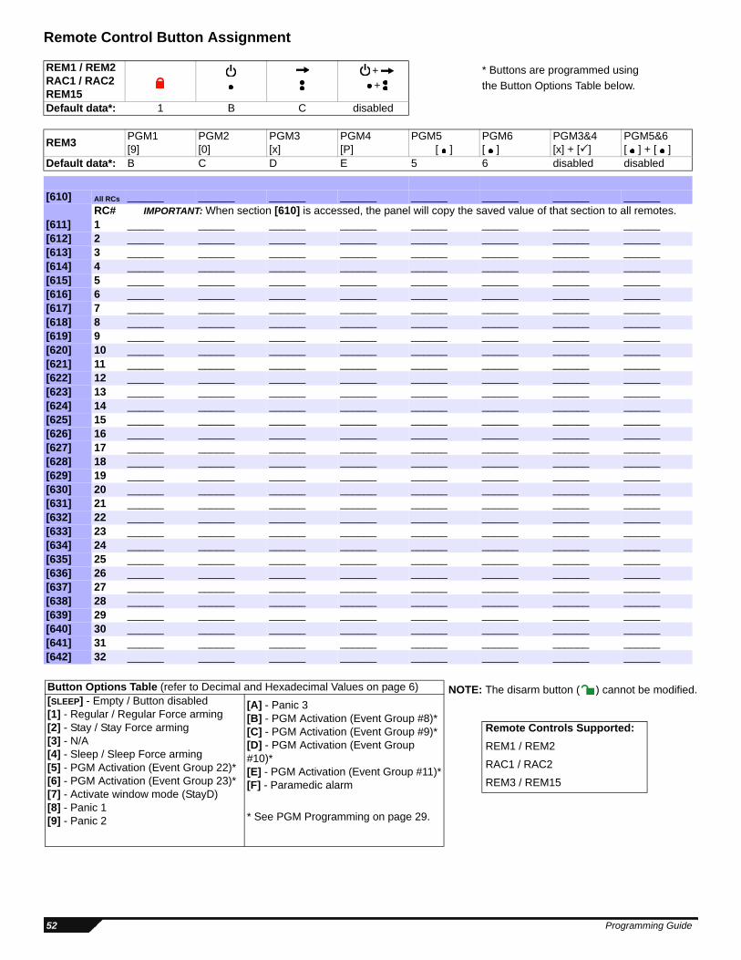
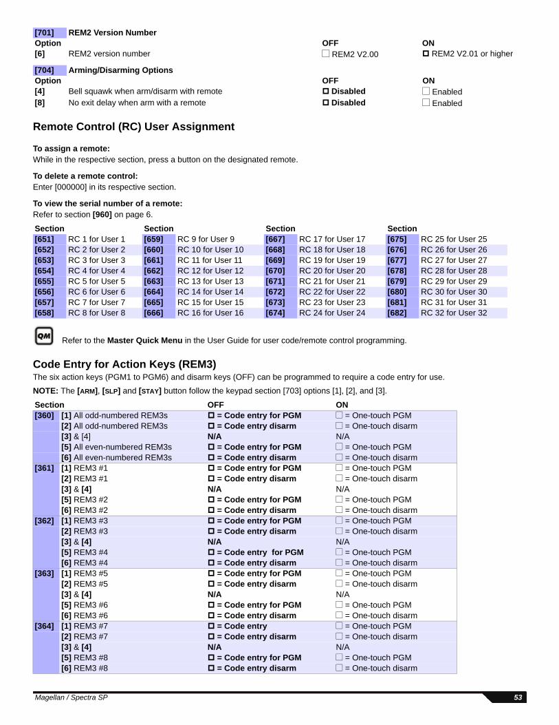
* These options apply to the REM3 remote control only.
Keypad Lockout
Partition ProgrammingNOTE: When using a K636 keypad, only partition 1 is available. To use both partitions, use any other compatible keypad.
Partition Labels
NOTE: For label character tables, see LCD Keypad Labels (K32LCD) on page 47.
[701] Keypad Options 1Option OFF ON[3] Confidential mode Disabled Enabled[4] To exit confidential mode Enter a code Press a key[5] Confidential mode timer 2 minutes 5 seconds[7] Display entry delay on LCD keypad (K32LCD) Disabled Enabled[8] Display exit delay on LCD keypad (K32LCD) Disabled Enabled
[704] Keypad Options 3Option OFF ON[5] Bell squawk when arm/disarm with a keypad Disabled Enabled[6] Beep on exit delay Disabled Enabled[7] No exit delay beeps and no bell squawk when stay/sleep arm Disabled Enabled
Section Data Description[716] ____/____/____ (000 to 255) minutes Keypad lockout delay (default 000)[717] ____/____/____ (000 to 255) attempt before locking Keypad lockout counter (default 000)
[700] PartitioningOption OFF ON[1] Partitioning Disabled Enabled
[965] Reset Partition LabelsOption OFF ON[3] Reset partition labels* Disabled Enabled* Ensure all other options are deselected. Press [ENTER] to reset the respective set of labels to default before exiting the section.
[741] Partition 1 OptionsOption OFF ON[1] Auto-arm on time Disabled Enabled[2] Auto-arm on no movement Disabled Enabled[3]&[4] Auto-arm arming mode See Table See Table
[5] Switch to stay arming if no entry delay zone is opened Disabled Enabled[6] Follow zones become entry delay 2 when delay zone is bypassed Disabled Enabled
[3] [4]
OFF OFF Regular
OFF ON Sleep
ON OFF Stay
Magellan / Spectra SP 19
Partition Timers
Refer to the Installer Quick Menu on page 65 for alternate entry/exit and bell cut-off timer programming.
System Programming
[742] Partition 2 Options
Option OFF ON
[1] Auto-arm on time Disabled Enabled[2] Auto-arm on no movement Disabled Enabled
[3]&[4]
Auto-arm arming mode See Table See Table
[5] Switch to stay arming if no entry delay zone is opened Disabled Enabled[6] Follow zones become entry delay 2 when delay zone is bypassed Disabled Enabled
Section Data Description[745] ____/____/____ (000 to 255) seconds Partition 1 exit delay (default 060)[746] ____/____/____ (000 to 255) seconds Partition 2 exit delay (default 060)[747] ____/____/____ (000 to 255) minutes Partition 1 bell cut-off (default 004)[748] ____/____/____ (000 to 255) minutes Partition 2 bell cut-off (default 004)[749] ____/____/____ (000 to 255) x 15 minutes Partition 1 no movement (default 000)[750] ____/____/____ (000 to 255) x 15 minutes Partition 2 no movement (default 000)[761] ____/____:____/___ HH: MM Auto-arm on time Partition 1 (default 00:00)[762] ____/____:____/____ HH: MM Auto-arm on time Partition 2 (default 00:00)
[700] General System OptionsOption OFF ON[2] Battery charging (350mA or 700mA)* 350mA 700mA[3] Audible trouble warning (except AC failure) Disabled Enabled[4] Audible trouble warning on AC failure Disabled Enabled[6] Exit delay termination Disabled Enabled[7] Tamper supervision on the bus module Disabled Enabled* Does not apply to SP4000 systems
[702] Panic OptionsOption OFF ON[1] Panic 1 Disabled Enabled[2] Panic 2 Disabled Enabled[3] Panic 3 Disabled Enabled[4] Panic 1: Report only or audible alarm Report only Audible[5] Panic 2: Report only or audible alarm Report only Audible[6] Panic 3: Report only or audible alarm Report only Audible
[703] Arming/Disarming Options Option OFF ON[5] Restrict arming on battery failure Disabled Enabled[6] Restrict arming on tamper failure (Zone + Bus Module
+ Wireless PGM)Disabled Enabled
[7] Restrict arming on wireless supervision trouble (Wireless zones + Wireless PGM)*
Disabled Enabled
* Does not apply to SP4000 systems.
[704] Arming/Disarming OptionsOption OFF ON[1] Regular arming switches to force arming Disabled Enabled[2] Stay arming switches to stay force arming Disabled Enabled[3] Sleep arming switches to sleep force arming Disabled Enabled
[3] [4]
OFF OFF Regular
OFF ON Sleep
ON OFF Stay
20 Programming Guide
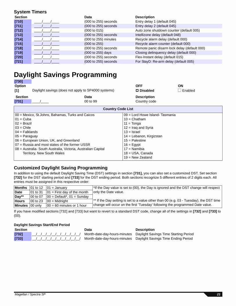
System Timers
Daylight Savings Programming
Customized Daylight Saving ProgrammingIn addition to using the default Daylight Saving Time (DST) settings in section [731], you can also set a customized DST. Set section [732] for the DST starting period and [733] for the DST ending period. Both sections recognize 5 different entries of 2 digits each. All entries must be assigned in this respective order:
If you have modified sections [732] and [733] but want to revert to a standard DST code, change all of the settings in [732] and [733] to (00).
Daylight Savings Start/End Period
Section Data Description[710] ____/____/____ (000 to 255) seconds Entry delay 1 (default 045)[711] ____/____/____ (000 to 255) seconds Entry delay 2 (default 045)[712] ____/____/____ (000 to 015) Auto zone shutdown counter (default 005)[713] ____/____/____ (000 to 255) seconds Intellizone delay (default 048)[714] ____/____/____ (000 to 255) minutes Recycle alarm delay (default 000)[715] ____/____/____ (000 to 255) Recycle alarm counter (default 000)[718] ____/____/____ (000 to 255) seconds Remote panic disarm lock delay (default 000)[719] ____/____/____ (000 to 255) days Closing delinquency delay (default 000)[720] ____/____/____ (000 to 255) seconds Flex-Instant delay (default 015)[721] ____/____/____ (000 to 255) seconds For StayD: Re-arm delay (default 005)
[730]Option OFF ON[1] Daylight savings (does not apply to SP4000 systems) Disabled Enabled
Section Data Description[731] ____/____ 00 to 99 Country code
Country Code List
00 = Mexico, St.Johns, Bahamas, Turks and Caicos01 = Cuba02 = Brazil03 = Chile04 = Falklands05 = Paraguay06 = European Union, UK, and Greenland07 = Russia and most states of the former USSR08 = Australia- South Australia, Victoria, Australian Capital Territory, New South Wales
09 = Lord Howe Island- Tasmania10 = Chatham11 = Tonga12 = Iraq and Syria13 = Israel14 = Lebanon, Kirgizstan15 = Palestine16 = Egypt17 = Namibia18 = USA, Canada19 = New Zealand
Months 01 to 12 01 = January *If the Day value is set to (00), the Day is ignored and the DST change will respect only the Date value.
** If the Day setting is set to a value other than 00 (e.g. 03 - Tuesday), the DST time change will occur on the first 'Tuesday' following the programmed Date value.
Date 01 to 31 01 = First day of the monthDay** 00 to 07 00 = Default*, 01 = SundayHours 00 to 23 00 = MidnightMinutes 00 only 00 = 60 minutes or 1 hour
Section Data Description[732] __/__/__/__/__/__/__/__/__/__/ Month-date-day-hours-minutes Daylight Savings Time Starting Period[733] __/__/__/__/__/__/__/__/__/__/ Month-date-day-hours-minutes Daylight Savings Time Ending Period
Magellan / Spectra SP 21
Communication ProgrammingThe Communication Programming section is divided into sections corresponding to each installation type. Begin by programming the General Communications Options, and then program for one or more of the following specific installation types:
• Landline - see page 24• GSM - (PCS Series GSM) - see page 25• Network - GPRS/IP (PCS Series GPRS / IP100) - see page 26NOTE: For increased security, it is suggested that redundant communication methods be installed.
Software Options
General Communications OptionsThe following sections apply to all systems that report to a monitoring station.
Security Features MG5000 MG5050 SP4000 SP5500 SP6000 SP7000
[900] WinLoad / BabyWare OptionsOption OFF ON[1] Call back Disabled Enabled[2] Automatic event buffer transmission Disabled Enabled
[910] ___/___/___/___ Panel ID NOTE: For increased communication security, change the default Panel ID and PC password.[911] ___/___/___/___ PC password
[915] ___/___/___/___/___/___/___/___/___/___/___/___/___/___/___/___/___/___/___/___/___/PC telephone number (landline / GSM communication only)
[801] Dialer OptionsOption OFF ON[1] Report system disarming Always After alarm[2] Report zone restore Bell cutoff Zone closure[3] & [4]
[5] Contact ID Override Disabled CID defaults / slow format custom
[802] Event Call Direction Options 1Option OFF ON[1] Call tel. #1 / monitoring rcvr. #1 for arm/disarm report codes Disabled Enabled[2] Call tel. #2 / monitoring rcvr. #2 for arm/disarm report codes Disabled Enabled[3] Call pager for arm/disarm report codes Disabled Enabled[5] Call tel. #1 / monitoring rcvr. #1 for alarm/restore report codes Disabled Enabled[6] Call tel. #2 / monitoring rcvr. #2 for alarm/restore report codes Disabled Enabled[7] Call pager for alarm/restore report codes Disabled Enabled
Auto-Test Report Transmission Options
[3] [4]
OFF OFFTransmit the test report code every time the days programmed in section [840] have elapsed at the time programmed in section [850] (default).
OFF ONWhen disarmed: Transmit test report code every time the time programmed in section [852] has elapsed. When armed: Transmit test report code every time the time programmed in section [851] has elapsed.
ON OFFThe control panel will transmit the test report code every hour on the minute value programmed in section [850] (the last two digits). Note that the first two digits of section [850] will be ignored. E.g. If 10:25 was programmed into section [850], the test report code would be transmitted at the 25th minute of every hour, i.e. 11:25, 12:25, etc.
ON ONThe test report code will be transmitted when any of the conditions of the second and third options listed above (options [3] = OFF and [4] = ON / options [3] = ON and [4] = OFF) are met.
22 Programming Guide
Communication Settings
General Timers
Communication Timers
[803] Event Call Direction Options 2Option OFF ON[1] Call tel. #1 / monitoring rcvr. #1 for tamper/restore report codes Disabled Enabled[2] Call tel. #2 / monitoring rcvr. #2 for tamper/restore report codes Disabled Enabled[3] Call pager for tamper/restore report codes Disabled Enabled[5] Call tel. #1 / monitoring rcvr. #1 for trouble/restore report codes Disabled Enabled[6] Call tel. #2 / monitoring rcvr. #2 for trouble/restore report codes Disabled Enabled[7] Call pager for trouble/restore report codes Disabled Enabled
[804] Event Call Direction Options 3Option OFF ON[1] Call tel. #1 / monitoring rcvr. #1 for special report codes Disabled Enabled[2] Call tel. #2 / monitoring rcvr. #2 for special report codes Disabled Enabled[3] Call pager for special report codes Disabled Enabled[5] Call personal tel. # on zone alarm (burglary/fire) Disabled Enabled[6] Call personal tel. # on panic alarms Disabled Enabled[7] Call personal tel. # on paramedic alarm Disabled Enabled[8] Call personal tel. # on panel power trouble Disabled Enabled
Section Data Description[810] ___/___ Reporting format
TEL1 TEL2 0 = Ademco Slow1 = Silent Knight Fast2 = Sescoa3 = Ademco Express4 = Ademco Contact ID (default)5 = SIA (not supported with GPRS/IP reporting)
[811] ___/___/___/___ Partition 1 Account number (landline / GSM communication only)[812] ___/___/___/___ Partition 2 Account number (landline / GSM communication only)
[836]* ____/____/____ (000 to 127) seconds Personal reporting delay* (default 005)
[837]* ____/____/____ (000 to 010) Personal reporting message repetition* (default 003)
[901]* ____/____/____ (000 to 255) rings Number of rings* (default 008)
[902]* ____/____/____ (000 to 255) sec. (max 127) Answering machine override delay* (default 030)
* This section also applies when using a VDMP3 Plug-In Voice Dialer.
Magellan / Spectra SP 23
VDMP3 Options
NOTE: For more VDMP3 options, see Communication Timers on page 23.
Landline CommunicationPanels can be programmed for landline reporting using the following sections:
* This option also applies to GSM communication.
Communication Settings
* This option also applies to GSM communication.
Refer to the Installer Quick Menu on page 65 and the Master Quick Menu in the User Guide for programming telephone numbers.
NOTE: To erase a phone number/numeric message, press the [SLEEP] key for each digit in the respective section.
[703] Arm/disarm with VDMP3Option OFF ON[8] Arm/disarm with VDMP3 Disabled Enabled
Section Data Description[841] ____/____/____ (000 to 032) Maximum voice dialing attempts - VDMP3 (default 008)
[800] Dialer OptionsOption OFF ON[1] & [2] See Table See Table
[3] Switch to pulse on 5th attempt Disabled Enabled
[4] Alternate dial Disabled Enabled[5] Force dial (must be enabled to comply with TBR-21) Disabled Enabled[6] DTMF dialing Disabled Enabled[7] Pulse ratio 1:2 1:1.5[8] Reporting* Dialer activated No dialer
Section Data
[815]* ___/___/___/___/___/___/___/___/___/___/___/___/___/___/___/___/___/___/___/___/___/___/___/___/___/___/ MONITORING STATION TELEPHONE NUMBER 1
[816]* ___/___/___/___/___/___/___/___/___/___/___/___/___/___/___/___/___/___/___/___/___/___/___/___/___/___/ MONITORING STATION TELEPHONE NUMBER 2
[817]* ___/___/___/___/___/___/___/___/___/___/___/___/___/___/___/___/___/___/___/___/___/___/___/___/___/___/ BACKUP TELEPHONE NUMBER
[818]* ___/___/___/___/___/___/___/___/___/___/___/___/___/___/___/___/___/___/___/___/___/___/___/___/___/___/ PAGER TELEPHONE NUMBER
[819]* ___/___/___/___/___/___/___/___/___/___/___/___/___/___/___/___/___/___/___/___/___/___/___/___/___/___/ NUMERIC MESSAGE SENT WITH PAGER REPORTING
Special Keys for Telephone Numbers
Press Action or Value[OFF] *[BYP] #[MEM] switch from pulse to tone dialing or vice versa[TBL] 4-second pause[SLEEP] deletes current digit[ ] inserts blank space
Telephone Line Monitoring (TLM) Options
[1] [2]
off off Disabled
off on Trouble only
on offWhen disarmed: Trouble onlyWhen armed: Audible alarm
on on Silent alarms become Audible alarm
24 Programming Guide
GSM CommunicationSystems that include the PCS Series (GSM) can be programmed for GSM communication using the following sections:
* This option also applies to landline communication.
NOTE: To erase a phone number/numeric message, press the [SLEEP] key for each digit in the respective section.
PCS Series Programming
[800] ReportingOption OFF ON[8] Reporting* Dialer activated Dialer deactivated* This option also applies to landline communication.Section Data[815]* ___/___/___/___/___/___/___/___/___/___/___/___/___/___/___/___/___/___/___/___/___/___/___/___/___/___/
MONITORING STATION TELEPHONE NUMBER 1[816]* ___/___/___/___/___/___/___/___/___/___/___/___/___/___/___/___/___/___/___/___/___/___/___/___/___/___/
MONITORING STATION TELEPHONE NUMBER 2[817]* ___/___/___/___/___/___/___/___/___/___/___/___/___/___/___/___/___/___/___/___/___/___/___/___/___/___/
BACKUP TELEPHONE NUMBER [818]* ___/___/___/___/___/___/___/___/___/___/___/___/___/___/___/___/___/___/___/___/___/___/___/___/___/___/
PAGER TELEPHONE NUMBER
[819]* ___/___/___/___/___/___/___/___/___/___/___/___/___/___/___/___/___/___/___/___/___/___/___/___/___/___/ NUMERIC MESSAGE SENT WITH PAGER REPORTING
Special Keys for Telephone Numbers
Press Action or Value[OFF] *[BYP] #[MEM] switch from pulse to tone dialing or vice versa[TBL] 4-second pause[SLEEP] deletes current digit[ ] inserts blank space
[805] GSM Options Option[1] & [2]
[3] & [4] Future use[5] & [6]
[7] Future useOFF ON
[8] GSM RF jamming supervision Disabled Enabled
GSM Reporting
[1] [2] Primary Backup
OFF OFF Landline Landline
OFF ON Landline GSM
ON OFF GSM Landline
ON ON GSM GSM
GSM No Service Trouble Feedback
[5] [6]
OFF OFF Disabled
OFF ON Trouble only
ON OFFWhen disarmed: Trouble onlyWhen armed: Audible alarm
ON ON Silent alarm becomes audible alarm
Magellan / Spectra SP 25
PCS Series (GSM) Settings
Table 6: SMS Language ID
Communication Report Codes
Communication Report Codes
Communication Restore Report Codes
Network Communication (GPRS/GSM)Systems that report using the PCS Series (GPRS) or the IP100 can be programmed for TCP/IP communication using the following sections:
IP100 / PCS Series (GPRS) Options
IP Account Numbers
Section Data Description[855] ___/___/___ (000 to 255) x 2 seconds GSM no service timer (default 016)[856] ___/___/___ (000 to 255) SMS language (default 000)
Language ID Language ID Language ID Language IDEnglish 000 Portuguese 006 Croatian 012 Slovak 018French 001 German 007 Greek 013 Chinese 019Spanish 002 Turkish 008 Hebrew 014 Serbian 020Italian 003 Hungarian 009 Russian 015 Future use 021 to 255Swedish 004 Czech 010 Bulgarian 016Polish 005 Dutch 011 Romanian 017
[966] Clear Communication Report CodesOption OFF ON[6] Clear report code for GSM lost communication with panel* Disabled Enabled* Ensure all other options are deselected. Press [ENTER] to clear the respective set of report codes before exiting the section.
[967] Reset Communication Report CodesOption OFF ON[6] Reset report code for GSM lost communication with panel* Disabled Enabled* Ensure all other options are deselected. Press [ENTER] to reset the respective set of report codes before exiting the section.
[879]* ____/____ PCS Series RF jam [884]* ____/____ GSM lost communication with panel ____/____ PCS Series no service ____/____ N/A ____/____ PCS Series module supervision lost ____/____ N/A ____/____ Receiver fail to communicate (GPRS) ____/____ N/A
[881]* ____/____ PCS Series RF jam ____/____ PCS Series no service ____/____ PCS Series module supervision lost ____/____ Receiver fail to communicate (GPRS)
* This section also applies to network communication programming.
[806] IP/GPRS Options Option[5] & [6]
OFF ON[7] Use dialer reporting As IP/GPRS reporting backup In addition to IP/GPRS reporting[8] Enable IP/GPRS reporting Disabled Enabled
ON OFF When disarmed: Trouble onlyWhen armed: Audible alarm
ON ON Silent alarm becomes audible alarm
26 Programming Guide
IP Receiver 1 Configuration
IP Receiver 2 Configuration
IP Receiver Backup Configuration
[929] ___/___/___ . ___/___/___ . ___/___/___ . ___/___/___IP ADDRESS WAN1 (E.G. 100.100.100.100) NOTE: FOR 1 OR 2 DIGIT NUMBERS, ADD “0”S BEFORE THE FIRST DIGIT
[930] ___/___/___/___/___IP PORT WAN1 (E.G. 10000)
VIEW STATUS / TO REGISTER, PRESS [ARM] (see Table 7 on page 28)
Magellan / Spectra SP 27
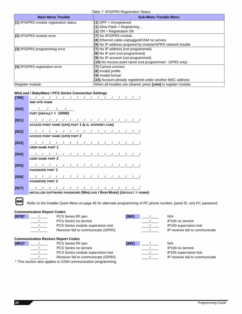
Table 7: IP/GPRS Registration Status
WinLoad / BabyWare / PCS Series Connection Settings
Refer to the Installer Quick Menu on page 65 for alternate programming of PC phone number, panel ID, and PC password.
Communication Report Codes
Communication Restore Report Codes
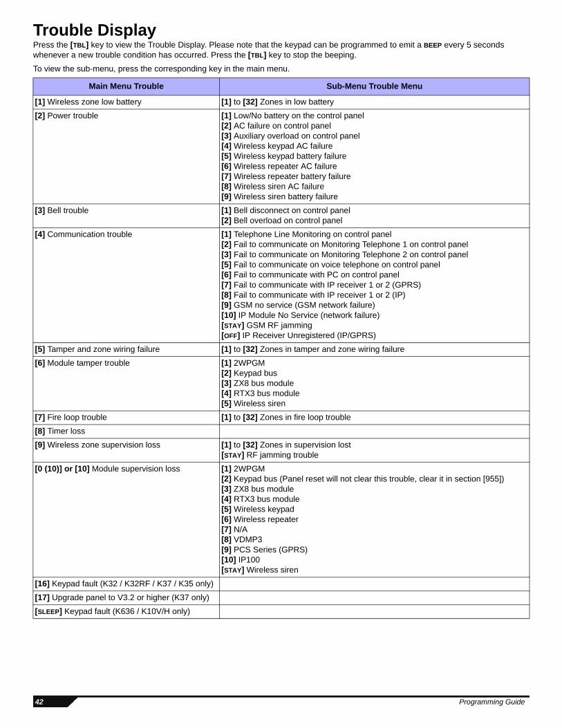
Main Menu Trouble Sub-Menu Trouble Menu
[1] IP/GPRS module registration status [1] OFF = Unregistered[1] Slow Flash = Registering...[1] ON = Registration OK
[2] IP/GPRS module error [7] No IP/GPRS module[8] Ethernet cable unplugged/GSM no service[9] No IP address acquired by module/GPRS network trouble
[3] IP/GPRS programming error [7] No IP address (not programmed)[8] No IP port (not programmed)[9] No IP account (not programmed)[10] No Access point name (not programmed - GPRS only)
[4] IP/GPRS registration error [7] Cannot connect[8] Invalid profile[9] Invalid format[10] Account already registered under another MAC address
Register module When all troubles are cleared, press [ARM] to register module.
[780] ___/___/___/___/___/___/___/___/___/___/___/___/___/___/___/___/SMS SITE NAME
[879]* ____/____ PCS Series RF jam [880] ____/____ N/A ____/____ PCS Series no service ____/____ IP100 no service ____/____ PCS Series module supervision lost ____/____ IP100 supervision lost ____/____ Receiver fail to communicate (GPRS) ____/____ IP receiver fail to communicate
[881]* ____/____ PCS Series RF jam [882] ____/____ N/A ____/____ PCS Series no service ____/____ IP100 no service ____/____ PCS Series module supervision lost ____/____ IP100 supervision lost ____/____ Receiver fail to communicate (GPRS) ____/____ IP receiver fail to communicate
* This section also applies to GSM communication programming.
28 Programming Guide
Programmable Output Programming
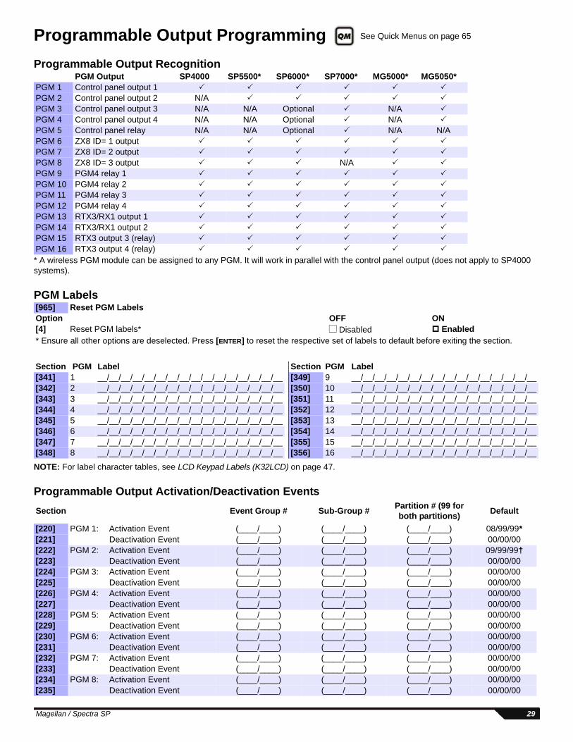
Programmable Output Recognition
* A wireless PGM module can be assigned to any PGM. It will work in parallel with the control panel output (does not apply to SP4000 systems).
PGM Labels
NOTE: For label character tables, see LCD Keypad Labels (K32LCD) on page 47.
[965] Reset PGM LabelsOption OFF ON[4] Reset PGM labels* Disabled Enabled* Ensure all other options are deselected. Press [ENTER] to reset the respective set of labels to default before exiting the section.
01 to 16 = Output number17 to 18 = Wireless repeater19 to 22 = Wireless keypad99 = Any output number
14 = Bypass programming 01 to 32 = User number99 = Any user number15 = User code activated output (Partition 1 only)
16 = Wireless smoke maintenance signal 01 to 32 = Zone number99 = Any zone number17 = Delay zone alarm transmission
18 = Zone signal strength weak 1 (Partition 1 only)19 = Zone signal strength weak 2 (Partition 1 only)20 = Zone signal strength weak 3 (Partition 1 only)21 = Zone signal strength weak 4 (Partition 1 only)22 = Button pressed on remote (see button option “5”) 01 to 32 = Remote control number
99 = Any remote control number23 = Button pressed on remote (see button option “6”)24 = Fire Delay started 01 to 32 = Zone number
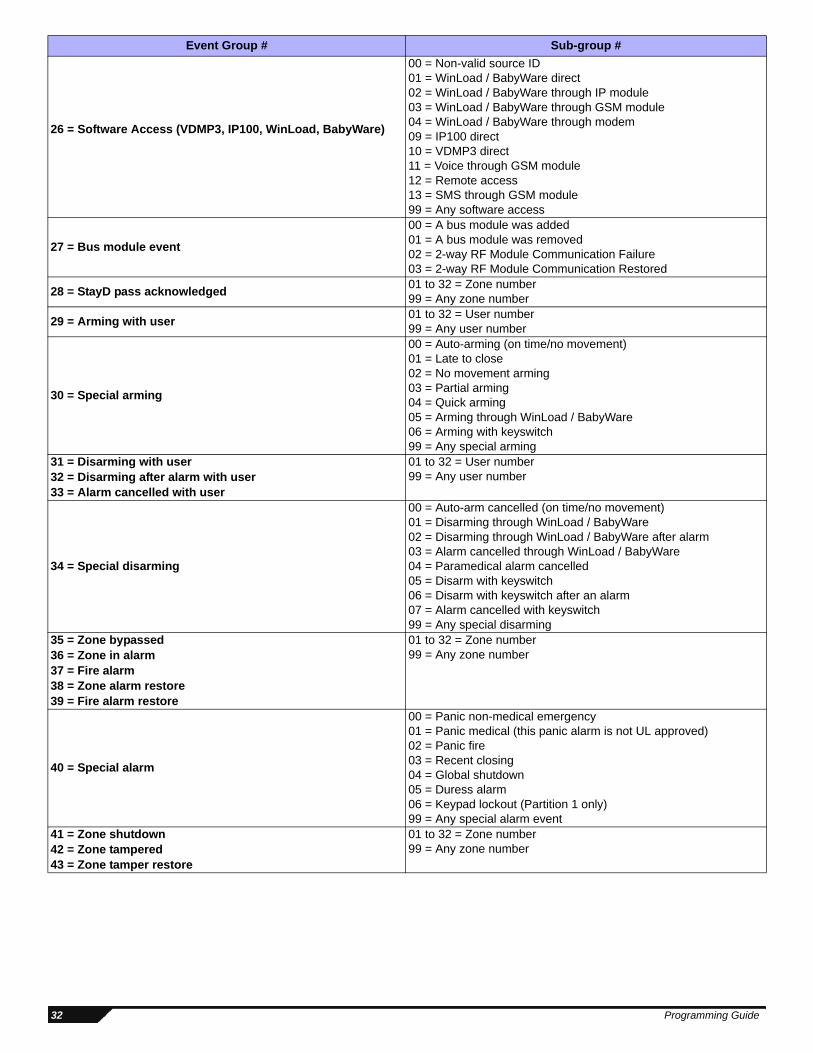
00 = Non-valid source ID01 = WinLoad / BabyWare direct02 = WinLoad / BabyWare through IP module03 = WinLoad / BabyWare through GSM module04 = WinLoad / BabyWare through modem09 = IP100 direct10 = VDMP3 direct11 = Voice through GSM module12 = Remote access13 = SMS through GSM module99 = Any software access
27 = Bus module event
00 = A bus module was added01 = A bus module was removed02 = 2-way RF Module Communication Failure03 = 2-way RF Module Communication Restored
28 = StayD pass acknowledged01 to 32 = Zone number99 = Any zone number
29 = Arming with user01 to 32 = User number99 = Any user number
30 = Special arming
00 = Auto-arming (on time/no movement)01 = Late to close02 = No movement arming03 = Partial arming04 = Quick arming05 = Arming through WinLoad / BabyWare06 = Arming with keyswitch99 = Any special arming
31 = Disarming with user 01 to 32 = User number99 = Any user number32 = Disarming after alarm with user
33 = Alarm cancelled with user
34 = Special disarming
00 = Auto-arm cancelled (on time/no movement)01 = Disarming through WinLoad / BabyWare02 = Disarming through WinLoad / BabyWare after alarm03 = Alarm cancelled through WinLoad / BabyWare04 = Paramedical alarm cancelled05 = Disarm with keyswitch06 = Disarm with keyswitch after an alarm07 = Alarm cancelled with keyswitch99 = Any special disarming
35 = Zone bypassed 01 to 32 = Zone number99 = Any zone number36 = Zone in alarm
37 = Fire alarm38 = Zone alarm restore39 = Fire alarm restore
40 = Special alarm
00 = Panic non-medical emergency01 = Panic medical (this panic alarm is not UL approved)02 = Panic fire03 = Recent closing04 = Global shutdown05 = Duress alarm 06 = Keypad lockout (Partition 1 only)99 = Any special alarm event
41 = Zone shutdown 01 to 32 = Zone number99 = Any zone number42 = Zone tampered
43 = Zone tamper restore
Event Group # Sub-group #
32 Programming Guide
44 = New trouble (Partition 1 only except sub-group 07 = both partitions)
00 = N/A01 = AC failure 02 = Battery failure 03 = Auxiliary current overload 04 = Bell current overload 05 = Bell disconnected 06 = Clock loss 07 = Fire loop trouble 08 = Fail to communicate to monitoring station telephone #1 09 = Fail to communicate to monitoring station telephone #2 11 = Fail to communicate to voice report 12 = RF jamming 13 = GSM RF jamming14 = GSM no service15 = GSM supervision lost16 = Fail To Communicate IP Receiver 1 (GPRS) 17 = Fail To Communicate IP Receiver 2 (GPRS)18 = IP Module No Service19 = IP Module Supervision Loss 20 = Fail To Communicate IP Receiver 1 (IP)21 = Fail To Communicate IP Receiver 2 (IP)99 = Any new trouble event
45 = Trouble restored
00 = Telephone line restored 01 = AC failure restore 02 = Battery failure restore 03 = Auxiliary current overload restore 04 = Bell current overload restore 05 = Bell disconnected restore 06 = Clock loss restore 07 = Fire loop trouble restore 08 = Fail to communicate to monitoring station telephone #1 restore 09 = Fail to communicate to monitoring station telephone #2 restore11 = Fail to communicate to voice report restore12 = RF jamming restore 13 = GSM RF jamming restore14 = GSM no service restore15 = GSM supervision lost restore16 = Fail To Communicate restore IP Receiver 1 (GPRS)17 = Fail To Communicate restore IP Receiver 2 (GPRS)18 = IP Module No Service restore19 = IP Module Supervision loss restore 20 = Fail To Communicate restore IP Receiver 1 (IP) 21 = Fail To Communicate restore IP Receiver 2 (IP) 99 = Any trouble restored event
46 = Bus / EBus / Wireless module new trouble (Partition 1 only)
00 = Bus / EBus / Wireless module communication fault 01 = Tamper trouble 02 = Power fail 03 = Battery failure 99 = Any bus module new trouble event
01 to 16 = Output17 to 18 = Wireless repeater19 to 22 = Wireless keypad27 to 30 = Wireless siren
57 = Non-medical alarm (paramedic)01 to 32 = User number99 = Any user number
58 = Zone forced 01 to 32 = Zone number99 = Any zone number59 = Zone included
64 = System Status*
00 = Follow Arm LED status**: 1. PGM pulse fast in alarm 2. PGM pulse fast in exit delay below 10 sec. 3. PGM pulse slow in exit delay over 10 sec. 4. PGM steady ON if armed 5. PGM OFF if disarmed
*On-board PGMs only** This event can be assigned to any partition. If assigned to both partitions, the PGM event will follow the priority of the list above, with #1 being the highest priority.
PGM 1[261]
PGM 2[262]
PGM 3[263]
PGM 4[264]
Option OFF ON OFF ON OFF ON OFF ON
[1] PGM Base Time (Off=Sec, On=Min) [2] PGM State (Off=N.O., On=N.C.) [3]* PGM Supervision [4] PGM Activation Mode (Off=Steady,
On=Pulse)
[5] PGM Pulse once every 30 seconds if armed [6] PGM Pulse on any alarm [7] PGM Pulse on any alarm
(OFF= Partition 1, On= Partition 2)
[8] N/A N/A N/A N/A N/A N/A N/A N/A N/A
Event Group # Sub-group #
34 Programming Guide
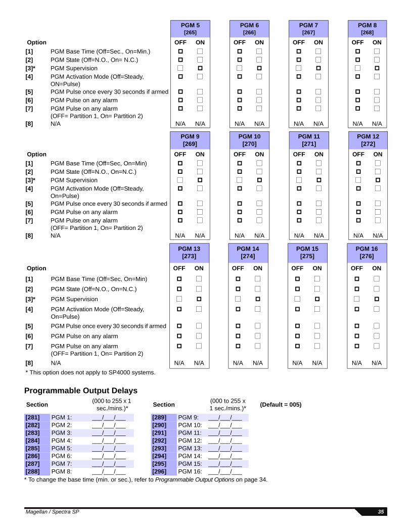
Programmable Output Delays
* To change the base time (min. or sec.), refer to Programmable Output Options on page 34.
PGM 5[265]
PGM 6[266]
PGM 7[267]
PGM 8[268]
Option OFF ON OFF ON OFF ON OFF ON
[1] PGM Base Time (Off=Sec., On=Min.) [2] PGM State (Off=N.O., On= N.C.) [3]* PGM Supervision [4] PGM Activation Mode (Off=Steady,
ON=Pulse)
[5] PGM Pulse once every 30 seconds if armed [6] PGM Pulse on any alarm [7] PGM Pulse on any alarm
(OFF= Partition 1, On= Partition 2)
[8] N/A N/A N/A N/A N/A N/A N/A N/A N/A
PGM 9[269]
PGM 10[270]
PGM 11[271]
PGM 12[272]
Option OFF ON OFF ON OFF ON OFF ON
[1] PGM Base Time (Off=Sec, On=Min) [2] PGM State (Off=N.O., On=N.C.) [3]* PGM Supervision
[4] PGM Activation Mode (Off=Steady, On=Pulse)
[5] PGM Pulse once every 30 seconds if armed [6] PGM Pulse on any alarm [7] PGM Pulse on any alarm
(OFF= Partition 1, On= Partition 2)
[8] N/A N/A N/A N/A N/A N/A N/A N/A N/A
PGM 13[273]
PGM 14[274]
PGM 15[275]
PGM 16[276]
Option OFF ON OFF ON OFF ON OFF ON
[1] PGM Base Time (Off=Sec, On=Min)
[2] PGM State (Off=N.O., On=N.C.)
[3]* PGM Supervision
[4] PGM Activation Mode (Off=Steady, On=Pulse)
[5] PGM Pulse once every 30 seconds if armed
[6] PGM Pulse on any alarm
[7] PGM Pulse on any alarm (OFF= Partition 1, On= Partition 2)
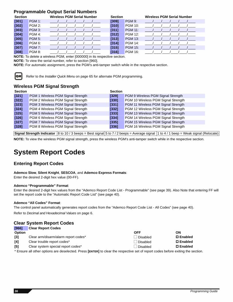
NOTE: To delete a wireless PGM, enter [000000] in its respective section.NOTE: To view the serial number, refer to section [960].NOTE: For automatic assignment, press the PGM’s anti-tamper switch while in the respective section.
Refer to the Installer Quick Menu on page 65 for alternate PGM programming.
Wireless PGM Signal Strength
NOTE: To view the wireless PGM signal strength, press the wireless PGM’s anti-tamper switch while in the respective section.
System Report Codes
Entering Report Codes
Ademco Slow, Silent Knight, SESCOA, and Ademco Express Formats: Enter the desired 2-digit hex value (00-FF).
Ademco “Programmable” Format: Enter the desired 2-digit hex values from the “Ademco Report Code List - Programmable” (see page 39). Also Note that entering FF will set the report code to the “Automatic Report Code List” (see page 40).
Ademco “All Codes” Format: The control panel automatically generates report codes from the “Ademco Report Code List - All Codes” (see page 40).
Refer to Decimal and Hexadecimal Values on page 6.
Section Section[321] PGM 1 Wireless PGM Signal Strength [329] PGM 9 Wireless PGM Signal Strength[322] PGM 2 Wireless PGM Signal Strength [330] PGM 10 Wireless PGM Signal Strength[323] PGM 3 Wireless PGM Signal Strength [331] PGM 11 Wireless PGM Signal Strength[324] PGM 4 Wireless PGM Signal Strength [332] PGM 12 Wireless PGM Signal Strength[325] PGM 5 Wireless PGM Signal Strength [333] PGM 13 Wireless PGM Signal Strength[326] PGM 6 Wireless PGM Signal Strength [334] PGM 14 Wireless PGM Signal Strength[327] PGM 7 Wireless PGM Signal Strength [335] PGM 15 Wireless PGM Signal Strength[328] PGM 8 Wireless PGM Signal Strength [336] PGM 16 Wireless PGM Signal Strength
Signal Strength Indicator 8 to 10 / 3 beeps = Best signal 5 to 7 / 2 beeps = Average signal 1 to 4 / 1 beep = Weak signal (Relocate)
[966] Clear Report CodesOption OFF ON[3] Clear arm/disarm/alarm report codes* Disabled Enabled[4] Clear trouble report codes* Disabled Enabled[5] Clear system special report codes* Disabled Enabled* Ensure all other options are deselected. Press [ENTER] to clear the respective set of report codes before exiting the section.
36 Programming Guide
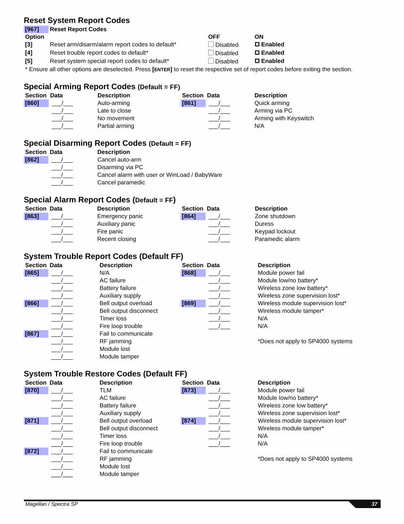
Reset System Report Codes
Special Arming Report Codes (Default = FF)
Special Disarming Report Codes (Default = FF)
Special Alarm Report Codes (Default = FF)
System Trouble Report Codes (Default FF)
System Trouble Restore Codes (Default FF)
[967] Reset Report CodesOption OFF ON[3] Reset arm/disarm/alarm report codes to default* Disabled Enabled[4] Reset trouble report codes to default* Disabled Enabled[5] Reset system special report codes to default* Disabled Enabled* Ensure all other options are deselected. Press [ENTER] to reset the respective set of report codes before exiting the section.
Section Data Description Section Data Description[860] ___/___ Auto-arming [861] ___/___ Quick arming
___/___ Late to close ___/___ Arming via PC ___/___ No movement ___/___ Arming with Keyswitch ___/___ Partial arming ___/___ N/A
Section Data Description[862] ___/___ Cancel auto-arm
___/___ Disarming via PC ___/___ Cancel alarm with user or WinLoad / BabyWare ___/___ Cancel paramedic
Section Data Description Section Data Description[863] ___/___ Emergency panic [864] ___/___ Zone shutdown
Section Data Description Section Data Description[865] ___/___ N/A [868] ___/___ Module power fail
___/___ AC failure ___/___ Module low/no battery* ___/___ Battery failure ___/___ Wireless zone low battery* ___/___ Auxiliary supply ___/___ Wireless zone supervision lost*
[866] ___/___ Bell output overload [869] ___/___ Wireless module supervision lost* ___/___ Bell output disconnect ___/___ Wireless module tamper* ___/___ Timer loss ___/___ N/A ___/___ Fire loop trouble ___/___ N/A
[867] ___/___ Fail to communicate ___/___ RF jamming *Does not apply to SP4000 systems ___/___ Module lost ___/___ Module tamper
Section Data Description Section Data Description[870] ___/___ TLM [873] ___/___ Module power fail
___/___ AC failure ___/___ Module low/no battery* ___/___ Battery failure ___/___ Wireless zone low battery* ___/___ Auxiliary supply ___/___ Wireless zone supervision lost*
[871] ___/___ Bell output overload [874] ___/___ Wireless module supervision lost* ___/___ Bell output disconnect ___/___ Wireless module tamper* ___/___ Timer loss ___/___ N/A ___/___ Fire loop trouble ___/___ N/A
[872] ___/___ Fail to communicate ___/___ RF jamming *Does not apply to SP4000 systems ___/___ Module lost ___/___ Module tamper
Magellan / Spectra SP 37
System Special Report Codes (Default = FF)
NOTE: For reporting code format instructions, see page 36.
NOTE: Refer to Decimal and Hexadecimal Values on page 6.
Section Data Description Section Data Description[875] ___/___ Cold start [876] ___/___ Installer in
___/___ Test report ___/___ Installer out ___/___ N/A ___/___ Closing Delinquency ___/___ Software out ___/___ N/A
[878] ___/___ Disarm with Keyswitch ___/___ Disarm with Keyswitch after
alarm ___/___ Alarm cancelled with
Keyswitch ___/___ N/A
38 Programming Guide
Ademco Contact ID Report CodesCID# Reporting Code Value CID# Reporting Code Value CID# Reporting Code ValueMedical Alarms - 100 321 Bell 1 48 429 Access program mode entry 91100 Medical alarm 01 322 Bell 2 49 430 Access program mode exit 92101 Pendant transmitter 02 323 Alarm relay 4A 431 Access threat level change 93102 Fail to report in 03 324 Trouble relay 4B 432 Access relay/trigger fail 94Fire Alarms - 110 325 Reversing relay 4C 433 Access RTE shunt 95110 Fire alarm 04 326 Notification appliance chk. #3 4D 434 Access DSM shunt 96111 Smoke 05 327 Notification appliance chk. #4 4E Arming - 440 and 450112 Combustion 06 System Peripheral Troubles - 330 and 340 441 Armed Stay 97113 Water flow 07 330 System peripheral 4F 442 Keyswitch armed Stay 98114 Heat 08 331 Polling loop open 50 450 Exception open/close 99115 Pull station 09 332 Polling loop short 51 451 Early open/close 9A116 Duct 0A 333 Expansion module failure 52 452 Late open/close 9B117 Flame 0B 334 Repeater failure 53 453 Failed to open 9C118 Near alarm 0C 335 Local printer paper out 54 454 Failed to close 9DPanic Alarms - 120 336 Local printer failure 55 455 Auto-arm failed 9E120 Panic Alarm 0D 337 Exp. module DC loss 56 456 Partial arm 9F121 Duress 0E 338 Exp. module low battery 57 457 Exit error (user) A0122 Silent 0F 339 Exp. module reset 58 458 User on premises A1123 Audible 10 341 Exp. module tamper 59 459 Recent close A2124 Duress - Access grated 11 342 Exp. module AC loss 5A System - 460125 Duress - Egress granted 12 343 Exp. module self-test fail 5B 461 Wrong code entry A3Burglar Alarms - 130 344 RF receiver jam detect 5C 462 Legal code entry A4130 Burglary 13 Communication Troubles - 350 and 360 463 Re-arm after alarm A5131 Perimeter 14 350 Communication 5D 464 Auto-arm time extended A6132 Interior 15 351 Telco 1 fault 5E 465 Panic alarm reset A7133 24-hour 16 352 Telco 2 fault 5F 466 Service ON/OFF premises A8134 Entry/Exit 17 353 Long range radio 60 Sounder Relay Disabled - 520135 Day/Night 18 354 Fail to communicate 61 520 Sounder/Relay disabled A9136 Outdoor 19 355 Loss of radio supervision 62 521 Bell 1 disabled AA137 Tamper 1A 356 Loss of central polling 63 522 Bell 2 disabled AB138 Near alarm 1B 357 Long range radio VSWR prob. 64 523 Alarm relay disabled AC139 Intrusion verified 1C Protection Loop Troubles - 370 524 Trouble relay disabled ADGeneral Alarms - 140 370 Protection loop 65 525 Reversing relay disabled AE140 General alarm 1D 371 Protection loop open 66 526 Notification appliance chk.#3 disabled AF141 Polling loop open 1E 372 Protection loop short 67 527 Notification appliance chk.#4 disabled B0142 Polling loop short 1F 373 Fire trouble 68 Modules - 530143 Expansion module failure 20 374 Exit error alarm 69 531 Module added B1144 Sensor tamper 21 375 Panic zone trouble 6A 532 Module removed B2145 Expansion module tamper 22 376 Hold-up zone trouble 6B Communication Disables - 550 and 560146 Silent burglary 23 377 Swinger trouble 6C 551 Dialer disabled B3147 Sensor supervision failure 24 378 Cross-zone trouble 6D 552 Radio transmitter disabled B424-hour Non-burglary - 150 and 160 Sensor Troubles - 380 and 390 Bypasses - 570150 24-hour non-burglary 25 380 Sensor trouble 6E 570 Zone bypass B5151 Gas detected 26 381 Loss of supervision - RF 6F 571 Fire bypass B6152 Refrigeration 27 382 Loss of supervision - RPM 70 572 24Hr. zone bypass B7153 Loss of heat 28 383 Sensor tamper 71 573 Burglary bypass B8154 Water leakage 29 384 RF transmitter low battery 72 574 Group bypass B9155 Foil break 2A 385 Smoke detector Hi sensitivity 73 575 Swinger bypass BA156 Day trouble 2B 386 Smoke detector Low sensitivity 74 576 Access zone shunt BB157 Low bottled gas level 2C 387 Intrusion detector Hi sensitivity 75 577 Access point bypass BC158 High temperature 2D 388 Intrusion detector Low sensitivity 76 Test/Misc. - 600159 Low temperature 2E 389 Sensor self-test failure 77 601 Manual trigger test BD161 Loss of air flow 2F 391 Sensor watch trouble 78 602 Periodic test report BE162 Carbon monoxide detected 30 392 Drift compensation error 79 603 Periodic RF transmission BF163 Tank level 31 393 Maintenance alert 7A 604 Fire test C0Fire Supervisory - 200 and 210 Open/Close - 400 605 Status report to follow C1200 Fire supervisory 32 400 Open/Close 7B 606 Listen-in to follow C2201 Low water pressure 33 401 Open/Close by user 7C 607 Walk test mode C3202 Low CO2 34 402 Group open/close 7D 608 Periodic test - system trouble present C4203 Gate valve sensor 35 403 Automatic open/close 7E 609 Video transmitter active C5204 Low water level 36 406 Cancel 7F 611 Point test OK C6205 Pump activated 37 407 Remote arm/disarm 80 612 Point not tested C7206 Pump failure 38 408 Quick arm 81 613 Intrusion zone walk tested C8System Troubles - 300 and 310 409 Keyswitch open/close 82 614 Fire zone walk tested C9300 System trouble 39 Remote Access - 410 615 Panic zone walk tested CA301 AC loss 3A 411 Call back request made 83 616 Service request CB302 Low system battery 3B 412 Success - download access 84 621 Event log reset CC303 RAM checksum bad 3C 413 Unsuccessful access 85 622 Event log 50% full CD304 ROM checksum 3D 414 System shutdown 86 623 Event log 90% full CE305 System reset 3E 415 Dialer shutdown 87 624 Event log overflow CF306 Panel program changed 3F 416 Successful upload 88 625 Time/Date reset D0307 Self-test failure 40 Access Control - 420 and 430 626 Time/Date inaccurate D1308 System shutdown 41 421 Access denied 89 627 Program mode entry D2309 Battery test failure 42 422 Access report by user 8A 628 Program mode exit D3310 Ground fault 43 423 Forced access 8B 629 32-hour event log marker D4311 Battery missing/dead 44 424 Egress denied 8C 630 Schedule change D5312 Power supply over current limit 45 425 Egress granted 8D 631 Exception schedule change D6313 Engineer reset 46 426 Access door propped open 8E 632 Access schedule change D7Sounder/Relay Troubles - 320 427 Access point door status monitor trouble 8F 654 System inactivity D8320 Sounder/relay 47 428 Access point request to exit 90
Magellan / Spectra SP 39
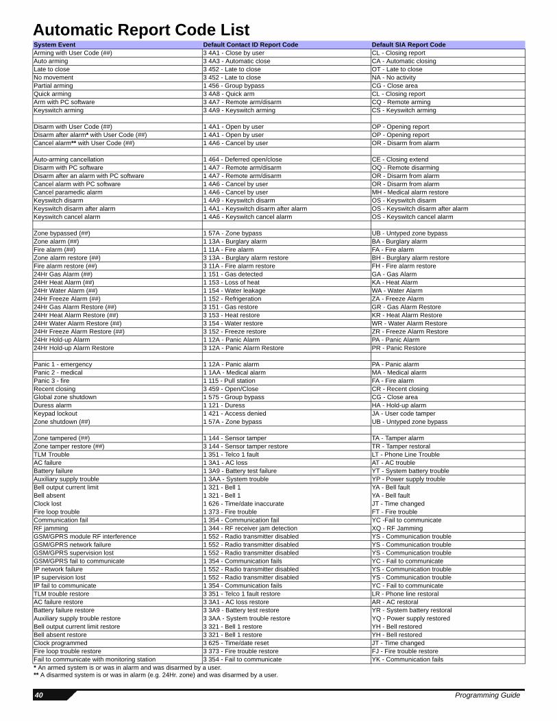
Automatic Report Code List System Event Default Contact ID Report Code Default SIA Report CodeArming with User Code (##) 3 4A1 - Close by user CL - Closing reportAuto arming 3 4A3 - Automatic close CA - Automatic closingLate to close 3 452 - Late to close OT - Late to closeNo movement 3 452 - Late to close NA - No activityPartial arming 1 456 - Group bypass CG - Close areaQuick arming 3 4A8 - Quick arm CL - Closing reportArm with PC software 3 4A7 - Remote arm/disarm CQ - Remote armingKeyswitch arming 3 4A9 - Keyswitch arming CS - Keyswitch arming
Disarm with User Code (##) 1 4A1 - Open by user OP - Opening reportDisarm after alarm* with User Code (##) 1 4A1 - Open by user OP - Opening reportCancel alarm** with User Code (##) 1 4A6 - Cancel by user OR - Disarm from alarm
Auto-arming cancellation 1 464 - Deferred open/close CE - Closing extendDisarm with PC software 1 4A7 - Remote arm/disarm OQ - Remote disarmingDisarm after an alarm with PC software 1 4A7 - Remote arm/disarm OR - Disarm from alarmCancel alarm with PC software 1 4A6 - Cancel by user OR - Disarm from alarmCancel paramedic alarm 1 4A6 - Cancel by user MH - Medical alarm restoreKeyswitch disarm 1 4A9 - Keyswitch disarm OS - Keyswitch disarmKeyswitch disarm after alarm 1 4A1 - Keyswitch disarm after alarm OS - Keyswitch disarm after alarmKeyswitch cancel alarm 1 4A6 - Keyswitch cancel alarm OS - Keyswitch cancel alarm
Zone bypassed (##) 1 57A - Zone bypass UB - Untyped zone bypassZone alarm (##) 1 13A - Burglary alarm BA - Burglary alarmFire alarm (##) 1 11A - Fire alarm FA - Fire alarmZone alarm restore (##) 3 13A - Burglary alarm restore BH - Burglary alarm restoreFire alarm restore (##) 3 11A - Fire alarm restore FH - Fire alarm restore24Hr Gas Alarm (##) 1 151 - Gas detected GA - Gas Alarm24Hr Heat Alarm (##) 1 153 - Loss of heat KA - Heat Alarm24Hr Water Alarm (##) 1 154 - Water leakage WA - Water Alarm24Hr Freeze Alarm (##) 1 152 - Refrigeration ZA - Freeze Alarm24Hr Gas Alarm Restore (##) 3 151 - Gas restore GR - Gas Alarm Restore24Hr Heat Alarm Restore (##) 3 153 - Heat restore KR - Heat Alarm Restore24Hr Water Alarm Restore (##) 3 154 - Water restore WR - Water Alarm Restore24Hr Freeze Alarm Restore (##) 3 152 - Freeze restore ZR - Freeze Alarm Restore24Hr Hold-up Alarm 1 12A - Panic Alarm PA - Panic Alarm24Hr Hold-up Alarm Restore 3 12A - Panic Alarm Restore PR - Panic Restore
Panic 1 - emergency 1 12A - Panic alarm PA - Panic alarmPanic 2 - medical 1 1AA - Medical alarm MA - Medical alarmPanic 3 - fire 1 115 - Pull station FA - Fire alarmRecent closing 3 459 - Open/Close CR - Recent closingGlobal zone shutdown 1 575 - Group bypass CG - Close areaDuress alarm 1 121 - Duress HA - Hold-up alarmKeypad lockout 1 421 - Access denied JA - User code tamperZone shutdown (##) 1 57A - Zone bypass UB - Untyped zone bypass
Zone tampered (##) 1 144 - Sensor tamper TA - Tamper alarmZone tamper restore (##) 3 144 - Sensor tamper restore TR - Tamper restoralTLM Trouble 1 351 - Telco 1 fault LT - Phone Line TroubleAC failure 1 3A1 - AC loss AT - AC troubleBattery failure 1 3A9 - Battery test failure YT - System battery troubleAuxiliary supply trouble 1 3AA - System trouble YP - Power supply troubleBell output current limit 1 321 - Bell 1 YA - Bell faultBell absent 1 321 - Bell 1 YA - Bell faultClock lost 1 626 - Time/date inaccurate JT - Time changedFire loop trouble 1 373 - Fire trouble FT - Fire troubleCommunication fail 1 354 - Communication fail YC -Fail to communicateRF jamming 1 344 - RF receiver jam detection XQ - RF JammingGSM/GPRS module RF interference 1 552 - Radio transmitter disabled YS - Communication troubleGSM/GPRS network failure 1 552 - Radio transmitter disabled YS - Communication troubleGSM/GPRS supervision lost 1 552 - Radio transmitter disabled YS - Communication troubleGSM/GPRS fail to communicate 1 354 - Communication fails YC - Fail to communicateIP network failure 1 552 - Radio transmitter disabled YS - Communication troubleIP supervision lost 1 552 - Radio transmitter disabled YS - Communication troubleIP fail to communicate 1 354 - Communication fails YC - Fail to communicateTLM trouble restore 3 351 - Telco 1 fault restore LR - Phone line restoralAC failure restore 3 3A1 - AC loss restore AR - AC restoralBattery failure restore 3 3A9 - Battery test restore YR - System battery restoralAuxiliary supply trouble restore 3 3AA - System trouble restore YQ - Power supply restoredBell output current limit restore 3 321 - Bell 1 restore YH - Bell restoredBell absent restore 3 321 - Bell 1 restore YH - Bell restoredClock programmed 3 625 - Time/date reset JT - Time changedFire loop trouble restore 3 373 - Fire trouble restore FJ - Fire trouble restoreFail to communicate with monitoring station 3 354 - Fail to communicate YK - Communication fails* An armed system is or was in alarm and was disarmed by a user.** A disarmed system is or was in alarm (e.g. 24Hr. zone) and was disarmed by a user.
40 Programming Guide
Installer Function KeysUse the following instructions to access the Installer Function features.
RF jamming 3 344 - RF receiver jam detection XH - RF Jamming RestoralGSM/GPRS module Rf interference restore 3 552 - Radio transmitter restore YK - Communication restoreGSM/GPRS network restore 3 552 - Radio transmitter restore YK - Communication restoreGSM/GPRS supervision restore 3 552 - Radio transmitter restore YK - Communication restoreGSM/GPRS fail to communicate restore 3 354 - Communication restore YK - Fail to communicate restoreIP network restore 3 552 - Radio transmitter restore YK - Communication restoreIP supervision restore 3 552 - Radio transmitter restore YK - Communication restoreIP fail to communicate restore 3 354 - Communication restore YK - Fail to communicate restore
Combus fault 1 333 - Expansion module failure ET - Expansion troubleModule tamper 1 341 - Expansion module tamper TA - Tamper alarmModule AC fail 1 342 - AC failure on module AT - Module AC failModule battery fail 1 338 - Battery failure on module YT - Module battery fail
Bus fault restore 3 333 - Expansion module failure restore ER - Expansion restoralModule tamper restore 3 341 - Expansion module tamper restore TR - Tamper restoralModule AC fail restore 3 342 - AC restored on module AR - Module AC fail restoreModule battery fail restore 3 338 - Battery failure on module YR - Module battery fail restore
Cold start 1 3A8 - System shutdown RR - Power upTest report engaged 1 6A2 - Periodic test report TX - Test reportPC software communication finished 1 412 - Successful - download access RS - Remote program successInstaller on site 1 627 - Program mode entry LB - Local programInstaller programming finished 1 628 - Program mode exit LS - Local program successMaintenance in 1 627 - Program mode entry LB - Local programMaintenance out 1 628 - Program mode exit LS - Local program successClosing delinquency 1 654 - System inactivity CD - System inactivityManual trigger test in 1 6A1 - Manual trigger test in TS - Manual trigger test inManual trigger test out 3 6A1 - Manual trigger test out TS - Manual trigger test outExit error 1 374 - Exit error EE - Exit errorRF module low battery 1 384 - RF transmitter low battery XT - Transmitter battery troubleRF module battery restore 3 384 - RF transmitter battery restore XR - Transmitter battery restoralRF zone supervision lost 1 381 - Loss of supervision - RF US - Untype zone supervisionRF zone supervision restore 3 381 - Supervision restore - RF UR - Untyped zone restoralRF module supervision lost 1 381 - Loss of supervision- RF US - Untype zone supervisionRF module supervision restore 3 381 - Loss of supervision- RF restore UR - Untyped zone restoralRF module tamper 1 145 - Expansion module tamper ES - Expansion device tamperRF module tamper restore 3 145 - Expansion module tamper restore EJ - Expansion device restoreParamedic alarm 1 1AA - Medical MA - Medical alarmZone forced 1 57A - Zone forced XW - Zone forcedZone included 3 57A - Zone included UU - Zone included
Function Action DescriptionTest Report
[ENTER]+[INSTALLER CODE] + [MEM]Send the “Test Report” report code programmed in section [875] (page 38) to the monitoring station
Cancel Communication [ENTER]+[INSTALLER CODE] + [STAY] Cancels all communication with the WinLoad / BabyWare software or with the monitoring station until the next reportable event
Answer WinLoad / BabyWare Software
[ENTER]+[INSTALLER CODE] + [SLEEP]Will force the console to answer an incoming call from the monitoring station that is using the WinLoad / BabyWare software
Will dial the PC telephone number programmed in section [915] (page 22) in order to initiate communication with a computer using the WinLoad / BabyWare software
Installer Test Mode[ENTER]+[INSTALLER CODE] + [TBL]
The installer test mode will allow you to perform walk tests where the siren will squawk to indicate opened zones. Press the [TBL] key again to exit
System Event Default Contact ID Report Code Default SIA Report Code
Magellan / Spectra SP 41
Trouble DisplayPress the [TBL] key to view the Trouble Display. Please note that the keypad can be programmed to emit a BEEP every 5 seconds whenever a new trouble condition has occurred. Press the [TBL] key to stop the beeping.
To view the sub-menu, press the corresponding key in the main menu.
Main Menu Trouble Sub-Menu Trouble Menu
[1] Wireless zone low battery [1] to [32] Zones in low battery
[2] Power trouble [1] Low/No battery on the control panel[2] AC failure on control panel[3] Auxiliary overload on control panel[4] Wireless keypad AC failure[5] Wireless keypad battery failure[6] Wireless repeater AC failure[7] Wireless repeater battery failure[8] Wireless siren AC failure[9] Wireless siren battery failure
[3] Bell trouble [1] Bell disconnect on control panel[2] Bell overload on control panel
[4] Communication trouble [1] Telephone Line Monitoring on control panel[2] Fail to communicate on Monitoring Telephone 1 on control panel[3] Fail to communicate on Monitoring Telephone 2 on control panel[5] Fail to communicate on voice telephone on control panel[6] Fail to communicate with PC on control panel[7] Fail to communicate with IP receiver 1 or 2 (GPRS)[8] Fail to communicate with IP receiver 1 or 2 (IP)[9] GSM no service (GSM network failure)[10] IP Module No Service (network failure) [STAY] GSM RF jamming[OFF] IP Receiver Unregistered (IP/GPRS)
[5] Tamper and zone wiring failure [1] to [32] Zones in tamper and zone wiring failure
[6] Module tamper trouble [1] 2WPGM[2] Keypad bus[3] ZX8 bus module[4] RTX3 bus module[5] Wireless siren
[7] Fire loop trouble [1] to [32] Zones in fire loop trouble
[8] Timer loss
[9] Wireless zone supervision loss [1] to [32] Zones in supervision lost[STAY] RF jamming trouble
[0 (10)] or [10] Module supervision loss [1] 2WPGM[2] Keypad bus (Panel reset will not clear this trouble, clear it in section [955])[3] ZX8 bus module[4] RTX3 bus module[5] Wireless keypad[6] Wireless repeater[7] N/A[8] VDMP3[9] PCS Series (GPRS)[10] IP100[STAY] Wireless siren
[16] Keypad fault (K32 / K32RF / K37 / K35 only)
[17] Upgrade panel to V3.2 or higher (K37 only)
[SLEEP] Keypad fault (K636 / K10V/H only)
42 Programming Guide
Wireless Repeater Programming (RPT1)
Wireless Repeater Assignment
NOTE: For automatic assignment, press the wireless repeater’s anti-tamper switch while in the respective section.
NOTE: For label character tables, see LCD Keypad Labels (K32LCD) on page 47.
NOTE: This section also applies to wireless siren programming see page 46.
Wireless Repeater Signal Strength
NOTE: To view the wireless repeater’s signal strength, press the wireless repeater’s anti-tamper switch while in the respective section.
Wireless Repeater OptionsNOTE: Remote control signals are always repeated.
[965] Reset Wireless Repeater/Siren LabelsOption OFF ON[6] Reset wireless repeater/siren labels* Disabled Enabled* Ensure all other options are deselected. Press [ENTER] to reset the respective set of labels to default before exiting the section.
Section[548] Wireless Repeater 1 Signal Strength[549] Wireless Repeater 2 Signal Strength
Signal Strength Indicator 8 to 10 / 3 beeps = Best signal 5 to 7 / 2 beeps = Average signal 1 to 4 / 1 beep = Weak signal (Relocate)
Option OFF ON OFF ON[1] Repeat Wireless Zone 1 Signals [2] Repeat Wireless Zone 2 Signals [3] Repeat Wireless Zone 3 Signals [4] Repeat Wireless Zone 4 Signals [5] Repeat Wireless Zone 5 Signals [6] Repeat Wireless Zone 6 Signals [7] Repeat Wireless Zone 7 Signals [8] Repeat Wireless Zone 8 Signals
Magellan / Spectra SP 43
RPT1 #1
[553]RPT1 #2
[563]
Option OFF ON OFF ON[1] Repeat Wireless Zone 9 Signals [2] Repeat Wireless Zone 10 Signals [3] Repeat Wireless Zone 11 Signals [4] Repeat Wireless Zone 12 Signals [5] Repeat Wireless Zone 13 Signals [6] Repeat Wireless Zone 14 Signals [7] Repeat Wireless Zone 15 Signals [8] Repeat Wireless Zone 16 Signals
RPT1 #1
[554]RPT1 #2
[564]
Option OFF ON OFF ON[1] Repeat Wireless Zone 17 Signals [2] Repeat Wireless Zone 18 Signals [3] Repeat Wireless Zone 19 Signals [4] Repeat Wireless Zone 20 Signals [5] Repeat Wireless Zone 21 Signals [6] Repeat Wireless Zone 22 Signals [7] Repeat Wireless Zone 23 Signals [8] Repeat Wireless Zone 24 Signals
RPT1 #1
[555]RPT1 #2
[565]
Option OFF ON OFF ON[1] Repeat Wireless Zone 25 Signals [2] Repeat Wireless Zone 26 Signals [3] Repeat Wireless Zone 27 Signals [4] Repeat Wireless Zone 28 Signals [5] Repeat Wireless Zone 29 Signals [6] Repeat Wireless Zone 30 Signals [7] Repeat Wireless Zone 31 Signals [8] Repeat Wireless Zone 32 Signals
NOTE: To view the wireless transmitter signal strength, press the wireless transmitter’s anti-tamper switch while in the respective section.
Wireless Keypad Programming (K32RF / K37)NOTE: For standard keypad programming, see page 18.
Automatic Wireless Keypad AssignmentAfter panel power-up, the control panel will open a 10 minute window for Automatic Assignment. Press and hold the [ ] and [BYP] key for three seconds on the respective keypad. The keypad is assigned to the control panel. Up to 8 wireless keypads can be assigned within the ten minute window.
Compatibility Check (K37 only)If the K37 is not compatible with the current panel version, the following Trouble will be displayed:
[TROUBLE : flash] [17 : on] If this occurs, update your MG/SP panel to version 3.2 or higher.
Wireless Keypad Labels
NOTE: For label character tables, see LCD Keypad Labels (K32LCD) on page 47.
Standard Wireless Keypad Assignment
NOTE: Enter serial number or press and hold the [ ] and [BYP] key for three seconds.
Section Section Section Section[101] Zone 1 [109] Zone 9 [117] Zone 17 [125] Zone 25[102] Zone 2 [110] Zone 10 [118] Zone 18 [126] Zone 26[103] Zone 3 [111] Zone 11 [119] Zone 19 [127] Zone 27[104] Zone 4 [112] Zone 12 [120] Zone 20 [128] Zone 28[105] Zone 5 [113] Zone 13 [121] Zone 21 [129] Zone 29[106] Zone 6 [114] Zone 14 [122] Zone 22 [130] Zone 30[107] Zone 7 [115] Zone 15 [123] Zone 23 [131] Zone 31[108] Zone 8 [116] Zone 16 [124] Zone 24 [132] Zone 32
Signal Strength Indicator 8 to 10 / 3 beeps = Best signal 5 to 7 / 2 beeps = Average signal 1 to 4 / 1 beep = Weak signal (Relocate)
[965] Wireless Keypad Labels Reset Option OFF ON[7] Reset wireless keypad labels* Disabled Enabled* Ensure all other options are deselected. Press [ENTER] to reset the respective set of labels to default before exiting the section.
[965] Wireless Siren/Repeater Labels Reset Option OFF ON[7] Reset wireless siren/repeater labels* Disabled Enabled* Ensure all other options are deselected. Press [ENTER] to reset the respective set of labels to default before exiting the section.
User ProgrammingRefer to the Installer Quick Menu on page 65 for installer or maintenance code programming.
Refer to the Master Quick Menu in the User Guide for user code/remote control programming.
System Codes
*4 or 6 digits according to section [701] option [1]. The control panel automatically removes the last 2 digits of the user access code if the length is changed from 6 digits to 4 digits. However, if the user access code length is changed from 4 to 6 digits, the control panel adds 2 digits to the end by using the first two digits.
User Code Options
WARNING: When section [400] is accessed, the panel will copy the saved value of that section to all user options- [404] to [432].
NOTE: The System Master, Master 1, and Master 2 user code options cannot be modified. However, if partitioning is not enabled, the user code options for Master 2 will match those of Master 1.
Section Data Description[395] ____/____/____(147 to lock, other to unlock) Installer Code Lock (default 000)[397] ____/____/____/____/____/____ Installer Code (default = 000000)*[398] ____/____/____/____/____/____ Maintenance Code (no default)[399] ____/____/____/____/____/____ System Master Code (default = 123456)*
Maintenance Code Limited Access TableThe Maintenance Code cannot access the following sections:[395] Installer code lock [817] Backup monitoring station telephone[397] Installer code [910] Panel ID[398] Maintenance code [911] PC password[815] Monitoring station telephone number 1 [970] Download memory key into panel [816] Monitoring station telephone number 2 [975] Upload panel into the memory key
[966] Clear User Report CodesOption OFF ON[2] Clear user report codes* Disabled Enabled* Ensure all other options are deselected. Press [ENTER] to clear the respective set of report codes before exiting the section.
[967] Reset User Report CodesOption OFF ON[2] Reset user report codes to default* Disabled Enabled* Ensure all other options are deselected. Press [ENTER] to reset the respective set of report codes before exiting the section.
Section ArmingDisarming/Cancel Alarm
Section ArmingDisarming/Cancel Alarm
[471] S. Master: ____/____ ____/____ [487] User 17: ____/____ ____/____[472] Master 1: ____/____ ____/____ [488] User 18: ____/____ ____/____[473] Master 2: ____/____ ____/____ [489] User 19: ____/____ ____/____[474] User 4: ____/____ ____/____ [490] User 20: ____/____ ____/____[475] User 5: ____/____ ____/____ [491] User 21: ____/____ ____/____[476] User 6: ____/____ ____/____ [492] User 22: ____/____ ____/____[477] User 7: ____/____ ____/____ [493] User 23: ____/____ ____/____[478] User 8: ____/____ ____/____ [494] User 24: ____/____ ____/____[479] User 9: ____/____ ____/____ [495] User 25: ____/____ ____/____[480] User 10: ____/____ ____/____ [496] User 26: ____/____ ____/____[481] User 11: ____/____ ____/____ [497]: User 27: ____/____ ____/____[482] User 12: ____/____ ____/____ [498] User 28: ____/____ ____/____[483] User 13: ____/____ ____/____ [499] User 29: ____/____ ____/____[484] User 14: ____/____ ____/____ [500] User 30: ____/____ ____/____[485] User 15: ____/____ ____/____ [501] User 31: ____/____ ____/____[486] User 16: ____/____ ____/____ [502] User 32: ____/____ ____/____
[965] Reset User LabelsOption OFF ON
Magellan / Spectra SP 51
Remote Control Button Assignment
REM1 / REM2RAC1 / RAC2 REM15
* Buttons are programmed using
the Button Options Table below.
Default data*: 1 B C disabled
REM3 PGM1[9]
PGM2[0]
PGM3[x]
PGM4[P]
PGM5 [ ]
PGM6[ ]
PGM3&4[x] + []
PGM5&6[ ] + [ ]
Default data*: B C D E 5 6 disabled disabled
[610] All RCs ______ ______ ______ ______ ______ ______ ______ ______RC# IMPORTANT: When section [610] is accessed, the panel will copy the saved value of that section to all remotes.
Button Options Table (refer to Decimal and Hexadecimal Values on page 6)[SLEEP] - Empty / Button disabled[1] - Regular / Regular Force arming[2] - Stay / Stay Force arming[3] - N/A[4] - Sleep / Sleep Force arming[5] - PGM Activation (Event Group 22)*[6] - PGM Activation (Event Group 23)*[7] - Activate window mode (StayD)[8] - Panic 1[9] - Panic 2
[A] - Panic 3[B] - PGM Activation (Event Group #8)*[C] - PGM Activation (Event Group #9)*[D] - PGM Activation (Event Group #10)*[E] - PGM Activation (Event Group #11)*[F] - Paramedic alarm
* See PGM Programming on page 29.
52 Programming Guide
Remote Control (RC) User Assignment
To assign a remote: While in the respective section, press a button on the designated remote.
To delete a remote control: Enter [000000] in its respective section.
To view the serial number of a remote: Refer to section [960] on page 6.
Refer to the Master Quick Menu in the User Guide for user code/remote control programming.
Code Entry for Action Keys (REM3)The six action keys (PGM1 to PGM6) and disarm keys (OFF) can be programmed to require a code entry for use.
NOTE: The [ARM], [SLP] and [STAY] button follow the keypad section [703] options [1], [2], and [3].
[701] REM2 Version NumberOption OFF ON[6] REM2 version number REM2 V2.00 REM2 V2.01 or higher
[704] Arming/Disarming Options Option OFF ON[4] Bell squawk when arm/disarm with remote Disabled Enabled[8] No exit delay when arm with a remote Disabled Enabled
Section Section Section Section[651] RC 1 for User 1 [659] RC 9 for User 9 [667] RC 17 for User 17 [675] RC 25 for User 25[652] RC 2 for User 2 [660] RC 10 for User 10 [668] RC 18 for User 18 [676] RC 26 for User 26[653] RC 3 for User 3 [661] RC 11 for User 11 [669] RC 19 for User 19 [677] RC 27 for User 27[654] RC 4 for User 4 [662] RC 12 for User 12 [670] RC 20 for User 20 [678] RC 28 for User 28[655] RC 5 for User 5 [663] RC 13 for User 13 [671] RC 21 for User 21 [679] RC 29 for User 29[656] RC 6 for User 6 [664] RC 14 for User 14 [672] RC 22 for User 22 [680] RC 30 for User 30[657] RC 7 for User 7 [665] RC 15 for User 15 [673] RC 23 for User 23 [681] RC 31 for User 31[658] RC 8 for User 8 [666] RC 16 for User 16 [674] RC 24 for User 24 [682] RC 32 for User 32
Section OFF ON[360] [1] All odd-numbered REM3s = Code entry for PGM = One-touch PGM
[2] All odd-numbered REM3s = Code entry disarm = One-touch disarm[3] & [4] N/A N/A[5] All even-numbered REM3s = Code entry for PGM = One-touch PGM[6] All even-numbered REM3s = Code entry disarm = One-touch disarm
WARNING: It is recommended that the smoke detectors be connected in a daisy chain configuration. Each control panel (except the SP5500) supports a maximum of five 2-wire smoke detectors.
NOTE: For 4-wire installation: Program the Activation Event so that the smoke detectors can be reset by pressing the [CLEAR] + [ENTER] keys for three seconds. See Event Group # 6 on page 30. For 2-wire installation (except SP5500): Press [CLEAR] + [ENTER] to automatically reset smoke.
PGM Power SourceAUX + terminal = must not exceed 700mA.External power supply = PGM1 and PGM2 cannot exceed
100mA or cannot exceed the power supply’s current limit.
Partial view of control panel
UL Warning: A 12Vdc / 7Ah battery is required to comply with UL fire requirements.
WARNING: Improper connection of the transformer may result in damage to the system.
WARNING: Disconnect battery before replacing the fuse.
Rechargeable BatteryUL/ULC - 12Vdc / 4Ah or 7Ah
56 Programming Guide
Connecting to WinLoad / BabyWare
Updating Firmware Using WinLoad / BabyWareTo update your system firmware:
1. Connect the product to your computer using a 307USB Direct Connect Interface or CV4USB Converter.
4. Verify the product information located in the In-Field Firmware Programmer window.If the firmware programmer does not automatically detect your control panel, click the Com port settings button and select the correct Com port. Then click the Refresh Product Info button to connect with the panel.
5. To check for new updates, click the Download Firmware from the web button.
6. From the Select Firmware drop-down box, select the firmware version you wish to install.orIf you have already downloaded the .pef/.puf file from paradox.com, click the [...] button and select the location of the .pef/.puf file.
7. Click the Update product firmware button.
8. When the download process finishes, the update is complete.
Serial Connector
Computer containing WinLoad / BabyWare software
307 adapter/CONV4USB Converter
4-pin connector cable
Standard DB-9 cable (9-pin serial cable)
Magellan / Spectra SP 57
Metal Box InstallationUse the numbered holes in the following diagram to identify the correct mounting location for the control panel being installed. If you require specific dimensions, contact Paradox Distributor Support.
Identify the correct mounting holes according to the following table:
8x10”Metal Box
11x11” Metal Box
Product 8x10” Metal Box Holes 11x11” Metal Box HolesMG5000* 3, 6, 9, 11, 14 6, 8, 12, 18, 20MG5050 11x11” box only 1, 4, 11, 19, 22SP4000 5, 7, 13, 16 7, 19, 20SP5500 1, 2, 17, 18 1, 2, 11, 19, 21SP6000 1, 2, 17, 18 1, 2, 11, 19, 21SP7000 11x11” box only 1, 4, 11, 19, 22* For UL recommended installation for the MG5000 only, place the PCB one notch lower than the mounting location.
Example: Install an MG5000 in an 8x10” box as follows:
3
6
11
14
9
3
45
9
10
11
1213
678
141516
2
1
18
17
1
23
4
5
2021
22
23
67
181916
17
8 9
10
12 13
14 15
11
58 Programming Guide
MG5000 PCB Layout
Refer to Single Zone Inputs on page 55
Refer to AC Power & Backup Battery Connections on page 56.
For the keypad’s zone configurations, refer to the Installer Quick Menu. If EOL is enabled: see section [706] option [2]. Also refer to Keypad Zone Connections on page 55.
AUX Power
Refer to transformer requirements on page 56 for Aux. Power Output. To connect additional wiring to auxiliary power, use the red (+) and black (-) keypad connectors. Auxiliary power will shut down if current exceeds 1.1A. If the auxiliary output is overloaded and is shut down, you must disconnect all loads from the output for at least 10 seconds before reconnecting any load back to the auxiliary output.
To provide maximum lightning protection we strongly recommend having separate earth connections for the dialer and zone ground terminals.
To metallic enclosure
Ground clamp
AWG#14 single conductor solid copper wire
Cold water pipe grounding
The "BELL" output will shutdown if the current exceeds 3A.
Disconnect telephone line before servicing.
Four pin connector can be used for quick installation of a keypad.
Do not cut, bend or alter the antennas and ensure that electrical wires do not cross over the antennae, as this may affect signal reception.
Paradox Memory Key (PMC-4 PMC-5)
Antennas
"RX" & “TX” LED:
Flashes quickly whenreceiving or transmitting RF signals from wireless devices.
"STATUS" LED:
Flash once every second = NormalFlashes ON 1 second and OFF 1 second = Any troubleAlways ON = Panel is using phone lineFast flash 6 seconds after power up = Installer lock enabled
This equipment must be installed and maintained by qualified service personnel only.For UL and C-UL warnings, refer to the UL and C-UL Warnings section at the back of the Reference & Installation Manual.
Used for In-Field Firmware upgrade through a 307USB Direct Connect Interface. See Connecting to WinLoad on page 57 for details.
EBUS and Dialer used with:VDMP3 plug-in voice module for voice reportingPCS Series GSM communicator module
Press and hold the RESET button for five seconds. The STATUS LED will start flashing. Within 2 seconds of this flashing, press the reset switch again. The panel will reset to default and restart.
The sum of the current drawn from the BELL
and AUX must be limited to 1.3A (40VA transformer strongly recommended). Exceeding this limit will overload the panel power supply and lead to complete system shutdown.
Connection for Self-Contained Bell/Siren
Max. number of keypads = 15 keypadsMax. aux. current = 700 mAMax. distance of bus module from panel = 76m (250 feet)Max. total run of wire = 230m (750 feet)
Charge LED:
Charging and Battery test LED
* If EOL is enabled: see section [706] option [2]. For the keypad’s zone configurations, refer to Installer Quick Menu on page 65. Also refer to keypad zone connections on page 55.
Magellan / Spectra SP 59
MG5050 PCB Layout
Used for In-Field Firmware upgrade through a 307USB Direct Connect Interface. See Connecting to WinLoad on page 57 for details.
Antennas
Do not cut, bend or alter the antennas and ensure that electrical wires do not cross over the antennae, as this may affect signal reception.
Four pin connector can be used for quick installation of a keypad.
Refer to AC Power & Backup Battery Connections on page 56.
Paradox Memory Key (PMC-4, PMC-5)
LEDs
Charge LED:
Charging and battery test LED
Status LED:
• Flash once every second = Normal
• Flashes ON 1 second and OFF 1 second = Any trouble
• Always ON = Panel is using phone line
• Fast flash 6 seconds after power up = Installer lock enabled
"RX" & “TX” LED:
Flashes quickly when receiving or transmitting RF signals from wireless devices.
To metallic enclosure
Ground clamp
AWG#14 single conductor solid copper wire
Cold water pipe grounding
To provide maximum lightning protection we strongly recommend having separate earth connections for the dialer and zone ground terminals.
The "BELL" output will shutdown if the current exceeds 3A.
Refer to Single Zone Inputs on page 55.
Max. number of keypads = 15 keypadsMax. aux. current = 700 mAMax. distance of bus module from panel = 76m (250 feet)Max. total run of wire = 230m (750 feet)
Disconnect telephone line before servicing.
AUX Power
Refer to transformer requirements on page 56 for Aux. Power Output. To connect additional wiring to auxiliary power, use the red (+) and black (-) keypad connectors. Auxiliary power will shut down if current exceeds 1.1A. If the auxiliary output is overloaded and is shut down, you must disconnect all loads from the output for at least 10 seconds before reconnecting any load back to the auxiliary output.
This equipment must be installed and maintained by qualified service personnel only.For UL and C-UL warnings, refer to the UL and C-UL Warnings section at the back of the Reference & Installation Manual.
The sum of the current
drawn from the BELL and AUX must be limited to 1.3A (40VA transformer strongly recommended). Exceeding this limit will overload the panel power supply and lead to complete system shutdown.
Connection for Self-Contained Bell/Siren
For the keypad’s zone configurations, refer to the Installer Quick Menu. If EOL is enabled: see section [706] option [2]. Also refer to Keypad Zone Connections on page 55.
Press and hold the RESET button for five seconds. The STATUS LED will start flashing. Within 2 seconds of this flashing, press the reset switch again. The panel will reset to default and restart.
* If EOL is enabled: see section [706] option [2]. For the keypad’s zone configurations, refer to Installer Quick Menu on page 65. Also refer to keypad zone connections on page 55.
*
Solid-state PGM (+/- trigger on PGM4 only)
J3 and J4 used with:VDMP3 plug-in voice module for voice reportingPCS Series GSM communicator module
60 Programming Guide
SP4000 PCB Layout
Used for connecting the IP100 Internet Module. Also used for In-Field Firmware upgrade through a 307USB Direct Connect Interface. See Connecting to BabyWare on page 57 for details.
DIALER and EBUS port used for voice reporting with the VDMP3 plug-in voice module.
Paradox Memory Key (PMC-4, PMC5)
Status LED:
• Flash once every second = Normal• Flashes ON 1 second and OFF 1
second = Any trouble • Always ON = Panel is using phone line • Fast flash 6 seconds after power up =
Installer lock enabled
Disconnect telephone line before servicing.
To metallic enclosure
Ground clamp
AWG#14 single conductor solid copper wire
Cold water pipe grounding
AUX Power
Refer to transformer requirements on page 56 for Aux. Power Output. To connect additional wiring to auxiliary power, use the red (+) and black (-) keypad connectors. Auxiliary power will shut down if current exceeds 450mA. If the auxiliary output is overloaded and is shut down, you must disconnect all loads from the output for at least 10 seconds before reconnecting any load back to the auxiliary output.
40VA transformer strongly recommended
The "BELL" output will shutdown if the current exceeds 3A.
To provide maximum lightning protection we strongly recommend having separate earth connections for the dialer and zone ground terminals.
Max. number of keypads = 15 keypads Max. aux. current = 650 mAMax. distance of keypad from panel = 76m (250 feet) Max. total run of wire = 230m (750 feet)
For the keypad’s zone configurations, refer to the Installer Quick Menu. If EOL is enabled: see section [706] option [2]. Also refer to Keypad Zone Connections on page 55.
Connect to any Common input.
Refer to AC Power & Backup Battery Connections on page 56.
Refer to Hardware Connections page 55.
This equipment must be installed and maintained by qualified service personnel only.For UL and C-UL warnings, refer to the UL and C-UL Warnings section at the back of the SP4000 Reference & Installation Manual.
Refer to PGM Connections on page 56.
EBUS port used for GSM reporting using the PCS Series GSM Communicator Module. If using a CVT485 Plug-In RS485 Converter, connect the PCS module to the RS485 bus.
Panel Reset
To perform a panel reset, refer to the SP4000 instructions on page 7.
Magellan / Spectra SP 61
SP5500 PCB Layout
Four pin connector can be used for quick installation of a SP5500 keypad.
Used for In-Field Firmware upgrade through a 307USB Direct Connect Interface. See Connecting to WinLoad on page 57 for details.
Paradox Memory Key (PMC-4, PMC5)
Refer to AC Power & Backup Battery Connections on page 56.
The "BELL" output will shutdown if the current exceeds 3A.
AUX Power
Refer to transformer requirements on page 56 for Aux. Power Output. To connect additional wiring to auxiliary power, use the red (+) and black (-) keypad connectors. Auxiliary power will shut down if current exceeds 1.1A. If the auxiliary output is overloaded and is shut down, you must disconnect all loads from the output for at least 10 seconds before reconnecting any load back to the auxiliary output.
This equipment must be installed and maintained by qualified service personnel only.For UL and C-UL warnings, refer to the UL and C-UL Warnings section at the back of the Reference & Installation Manual.
The sum of the current drawn from the BELL and AUX must be limited to 1.3A (40VA transformer strongly recommended). Exceeding this limit will overload the panel power supply and lead to complete system shutdown.
Connection for Self-Contained Bell/Siren
To provide maximum lightning protection we strongly recommend having separate earth connections for the dialer and zone ground terminals.
Max. number of keypads = 15 keypadsMax. aux. current = 700 mAMax. distance of bus module from panel = 76m (250 feet)Max. total run of wire = 230m (750 feet)
Disconnect telephone line before servicing.
To metallic enclosure
Ground clamp
AWG#14 single conductor solid copper wire
Cold water pipe grounding
For the keypad’s zone configurations, refer to the Installer Quick Menu. If EOL is enabled: see section [706] option [2]. Also refer to Keypad Zone Connections on page 55.
Refer to Single Zone Inputs on page 55.
PGM +/- trigger not supported by the SP5500
Press and hold the RESET button for five seconds. The STATUS LED will start flashing. Within 2 seconds of this flashing, press the reset switch again. The panel will reset to default and restart.
Charge LED:
Charging and battery test LED
Status LED:
• Flash once every second = Normal• Flashes ON 1 second and OFF 1 second = Any trouble • Always ON = Panel is using phone line • Fast flash 6 seconds after power up = Installer lock enabled
EBUS and Dialer used with:VDMP3 plug-in voice module for voice reportingPCS Series GSM communicator module
* If EOL is enabled: see section [706] option [2]. For the keypad’s zone configurations, refer to Installer Quick Menu on page 65. Also refer to keypad zone connections on page 55.
62 Programming Guide
SP6000 PCB Layout
Four pin connector can be used for quick installation of a keypad.
Used for In-Field Firmware upgrade through a 307USB Direct Connect Interface. See Connecting to WinLoad on page 57 for details.
Paradox Memory Key (PMC-4, PMC-5)
Refer to AC Power & Backup Battery Connections on page 56.
The "BELL" output will shutdown if the current exceeds 3A.
AUX Power
Refer to transformer requirements on page 56 for Aux. Power Output. To connect additional wiring to auxiliary power, use the red (+) and black (-) keypad connectors. Auxiliary power will shut down if current exceeds 1.1A. If the auxiliary output is overloaded and is shut down, you must disconnect all loads from the output for at least 10 seconds before reconnecting any load back to the auxiliary output.
This equipment must be installed and maintained by qualified service personnel only.For UL and C-UL warnings, refer to the UL and C-UL Warnings section at the back of the Reference & Installation Manual.
The sum of the current drawn from the BELL and AUX must be limited to 1.3A (40VA transformer strongly recommended). Exceeding this limit will overload the panel power supply and lead to complete system shutdown.
Connection for Self-Contained Bell/Siren
To provide maximum lightning protection we strongly recommend having separate earth connections for the dialer and zone ground terminals.
Max. number of keypads = 15 keypadsMax. aux. current = 700 mAMax. distance of bus module from panel = 76m (250 feet)Max. total run of wire = 230m (750 feet)
Disconnect telephone line before servicing.
To metallic enclosure
Ground clamp
AWG#14 single conductor solid copper wire
Cold water pipe grounding
For the keypad’s zone configurations, refer to the Installer Quick Menu. If EOL is enabled: see section [706] option [2]. Also refer to Keypad Zone Connections on page 55.
Refer to Single Zone Inputs on page 55.
PGM Trigger: This jumper allows you to choose whether the solid state relay PGMs are grounded (-), or give out 12V (+).
Press and hold the RESET button for five seconds. The STATUS LED will start flashing. Within 2 seconds of this flashing, press the reset switch again. The panel will reset to default and restart.
When using an SP6000 panel in conjunction with an RTX3, all K32 and K10V/H keypads must be versions 2.0 or higher.
* If EOL is enabled: see section [706] option [2]. For the keypad’s zone configurations, refer to Installer Quick Menu on page 65. Also refer to keypad zone connections on page 55.
*
EBUS and Dialer used with:VDMP3 plug-in voice module for voice reportingPCS Series GSM communicator module
LEDs
Charge LED:Charging and battery test LED
Status LED:
• Flash once every second = Normal• Flashes ON 1 second and OFF 1 second = Any trouble • Always ON = Panel is using phone line • Fast flash 6 seconds after power up = Installer lock enabled
Magellan / Spectra SP 63
SP7000 PCB Layout
Four pin connector can be used for quick installation of a keypad.
Used for In-Field Firmware upgrade through a 307USB Direct Connect Interface. See Connecting to WinLoad on page 57 for details.
Paradox Memory Key (PMC-4, PMC-5)
Refer to AC Power & Backup Battery Connections on page 56.
The "BELL" output will shutdown if the current exceeds 3A.
AUX Power
Refer to transformer requirements on page 56 for Aux. Power Output. To connect additional wiring to auxiliary power, use the red (+) and black (-) keypad connectors. Auxiliary power will shut down if current exceeds 1.1A. If the auxiliary output is overloaded and is shut down, you must disconnect all loads from the output for at least 10 seconds before reconnecting any load back to the auxiliary output.
This equipment must be installed and maintained by qualified service personnel only.
For UL and C-UL warnings, refer to the UL and C-UL Warnings section at the back of the Reference & Installation Manual.
The sum of the current drawn from the BELL and AUX must be limited to 1.3A (40VA transformer strongly recommended). Exceeding this limit will overload the panel power supply and lead to complete system shutdown.
Connection for Self-Contained Bell/Siren
To provide maximum lightning protection we strongly recommend having separate earth connections for the dialer and zone ground terminals.
Max. number of keypads = 15 keypadsMax. aux. current = 700 mAMax. distance of bus module from panel = 76m (250 feet)Max. total run of wire = 230m (750 feet)
Disconnect telephone line before servicing.
To metallic enclosure
Ground clamp
AWG#14 single conductor solid copper wire
Cold water pipe grounding
For the keypad’s zone configurations, refer to the Installer Quick Menu. If EOL is enabled: see section [706] option [2]. Also refer to Keypad Zone Connections on page 55.
Refer to Single Zone Inputs on page 55.
PGM Trigger: This jumper allows you to choose whether the solid state relay PGMs are grounded (-), or give out 12V (+). Upper Inputs = Zones 9 to 16
Lower Inputs = Zones 1 to 8
Press and hold the RESET button for five seconds. The STATUS LED will start flashing. Within 2 seconds of this flashing, press the reset switch again. The panel will reset to default and restart.
* If EOL is enabled: see section [706] option [2]. For the keypad’s zone configurations, refer to Installer Quick Menu on page 65. Also refer to keypad zone connections on page 55.
*
Z1 Z2 Z3 Z4 C Z5 Z6 Z7 Z8 C
Z9 Z10 Z11 Z12 C Z13 Z14 Z15 Z16 C
EBUS and Dialer used with:VDMP3 plug-in voice module for voice reportingPCS Series GSM communicator module
May be labeled ADM2 on some panels
May be labeled SERIAL on some panels
LEDs
Charge LED:Charging and battery test LED
Status LED:
• Flash once every second = Normal• Flashes ON 1 second and OFF 1 second = Any trouble • Always ON = Panel is using phone line • Fast flash 6 seconds after power up = Installer lock enabled
64 Programming Guide
Installer Quick Menu
Zones
Keypad Zone Number Assignment (Keypad Programming)
Delays
Time and Date
Walk Test Mode
Installer and Maintenance Codes
Step Action Details1 + [INSTALLER CODE] = flash. Programmed zones are lit (button or LED depending on keypad).
[MAINTENANCE CODE] may also be used.2 [ZONE NUMBER] 2 digits: 01 to 323 [ENROLL OR ERASE ZONE] Wireless zone = open/close cover or press learn/tamper switch. Hardwired zone =
Press [ENTER]. To erase a programmed zone, press [SLEEP] for 3 seconds.4 [ZONE TYPE] Refer to page 14 for the zone type (zone definition).5 Assign Partition
[1] and/or [2] + [ENTER]Assign the zone to one or both partitions and press [ENTER]. By default, all zones are assigned to partition 1. Goes to next available zone.
NOTE: Partition 2 status LEDs, display the signal strength of the selected wireless zone (4 LEDs = best signal; 1 LED = weak signal; No LEDs = hardwired panel/keypad zone)
Step Action Details1 [ENTER] + [INSTALLER CODE] [ARM] + [STAY] = flash. [MAINTENANCE CODE] may also be used.2 Press and hold (3sec) [ARM] + [STAY] = on.
3 [ZONE NUMBER] + [ENTER]* K32 / K32LCD / K35 = 2 digits: 01 to 32K636 / K10V/H = 1 digit: 1 to 0(10)* To erase a keypad zone number, press [CLEAR], then [ENTER].
Step Action Details1 + [INSTALLER CODE] = flash. [MAINTENANCE CODE] may also be used.
4 [000] to [255] Entry/Exit Delay = seconds / Bell Cut-Off = minutes
Step Action Details1 + [INSTALLER CODE] = flash. [MAINTENANCE CODE] may also be used.
2 + [5]
4 [HH:MM] Enter time. If HH = 13 or more, skip to step 6.5 [TIME FORMAT] Enter time format ([1] = 24hr; [2] = AM; [3] = PM).6 [YYYY/MM/DD] Enter date.
Step Action Details1 + [INSTALLER CODE] = flash. [MAINTENANCE CODE] may also be used.
2
3 [6] Activates or deactivates Walk Test Mode.
Step Action Details1 + [INSTALLER CODE] = flash.
2
3 [7] = Installer Code[8] = Maintenance Code
4 [CODE]* Enter 4- or 6-digit code.* To erase a code, press the [SLEEP] key for 3 seconds.5 [CONFIRM CODE] Re-enter 4- or 6-digit code.
Magellan / Spectra SP 65
WinLoad / BabyWare
Monitoring Phone #
Communicator
Cancel Communication
Step Action Details1 + [INSTALLER CODE] = flash.
2
3 [9]4 [PHONE #] + [ENTER]* Enter PC phone # (up to 32 digits) and press [ENTER].* To erase WinLoad / BabyWare
phone #, panel ID, and PC password, press the [SLEEP] key for 3 seconds.5 [PANEL ID] Enter 4-digit Panel ID6 [PC PASSWORD] Enter 4-digit PC Password
Step Action Details1 + [INSTALLER CODE] = flash.
2
3 [1]4 [PHONE #] + [ENTER]* Enter monitoring station phone # (up to 32 digits) and press [ENTER].* To erase monitoring
phone #, reporting format, and account #s, press the [SLEEP] key for 3 seconds.5 [PARTITION 1 ACCOUNT #]6 [1] = CID
[2] = SIA NOTE: SIA is not supported with GPRS/IP reporting7 [PARTITION 2 ACCOUNT #]
Step Action Details1 + [INSTALLER CODE] = flash. [MAINTENANCE CODE] may also be used, however, it cannot modify the
backup phone number.2
3 [2] = Backup Phone #[3] = Personal Phone #1[4] = Personal Phone #2[5] = Personal Phone #3[6] = Personal Phone #4[7] = Personal Phone #5[8] = Pager #
4 [PHONE #] + [ENTER]* Enter phone # (up to 32 digits) and press [ENTER]. Goes to next phone#, or go to step 5 if [8] = Pager # was selected. To erase a phone number pager message, press the [SLEEP] key for 3 seconds.
5 [MESSAGE] + [ENTER] Step 5 for Pager # only. Enter pager message and press [ENTER].
Step Action Details1 + [INSTALLER CODE] = flash. [MAINTENANCE CODE] may also be used.
2
3 [9] Cancels all communication with WinLoad / BabyWare / GSM module.
66 Programming Guide
PGMs Step Action Details1 + [INSTALLER CODE] = flash. [MAINTENANCE CODE] may also be used.
2
3 [PGM NUMBER] 2 digits: 01 to 164 [ENROLL OR ERASE PGM]* Wireless PGM = Open/close cover. Hardwired PGM = press [ENTER]. To erase a PGM,
press the [SLEEP] key for 3 seconds. 5 [PGM TYPE] 1 = Follow Button or 5 = Follow Bell
2 = Follow Button or 6 = Follow Arm3 = Follow Zone 7 = Follow Stay arm4 = Follow Alarm 8 = Follow Sleep arm
Audible trouble warning ..................................................... 20Auto test report .................................................................. 23Auto test report time of day ............................................... 23Auto-arm options ............................................................... 19
Programming Guide
BBabyWare
Connecting .................................................................57Instructions .................................................................57Quick menu ................................................................66Through PCS module ................................................28
Bus ModuleClear Trouble ...............................................................6Labels ........................................................................16
CCancel communication .......................................................66Check-in supervision time ..................................................17Codes ...................................................................................7Communication
Communicator - quick menu ..............................................66Comparison chart .................................................................4Confidential mode ..............................................................19Contact ID override ............................................................22Custom zone definitions .....................................................15
DData entry / display ..............................................................6Date and time .....................................................................65Daylight savings .................................................................21Decimal and hexadecimal values ........................................6Delay
No Service Timer .......................................................26Options .......................................................................25SMS Language ..........................................................26
QQuick menu ........................................................................65
RRecent closing delay ..........................................................23REM2 version number .......................................................53REM3 - Action keys ...........................................................53Remote control
Action keys (REM3) ...................................................53Button assignment .....................................................52REM2 version number ...............................................53Serial number display ..................................................6User assignment ........................................................53
Report CodesClear system report codes .........................................36Clear user ..................................................................51Clear zone report codes .............................................18Reset system report codes ........................................37Reset user ..................................................................51Reset zone report codes ............................................18Special arming report codes ......................................37System Trouble ..........................................................37
Test mode .......................................................................... 41Test report ......................................................................... 41Time and date .................................................................... 65Timers
For technical support in Canada or the U.S., call 1-800-791-1919, Monday to Friday from 8:00 a.m. to 8:00 p.m. EST. For technical support outside Canada and the U.S., call 00-1-450-491-7444, Monday to Friday from 8:00 a.m. to 8:00 p.m. EST.
Please feel free to visit our website at www.paradox.com
The whole Paradox team wishes you a successful and easy installation.We hope this product performs to your complete satisfaction. Should you have any questions or comments, please visit