3225 Uplands Drive Development Section 04 05 12 MASONRY MORTAR AND GROUT Page 1 of 3 □ Part 1 General 1.1 RELATED SECTIONS .1 Section 04 22 00 - Concrete Unit Masonry. 1.2 REFERENCES .1 Canadian Standards Association (CSA International). .1 CSA A179-04 (R2009), Mortar and Grout for Unit Masonry. 1.3 SUBMITTALS .1 Product Data. .1 Submit manufacturer's printed product literature, specifications and data sheet to Consultant in digital (PDF) format. .2 Submit copies of WHMIS MSDS - Material Safety Data Sheets to Consultant in digital (PDF) format. Indicate VOC's mortar, grout, parging, colour additives and admixtures. .2 Samples. .1 Submit samples to Consultant for review. .2 Submit samples of mortar and coloured mortar. For colour mortar provide full selection of available colours from manufacturer. .3 Manufacturer's Instructions. .1 Submit manufacturer's installation instructions to Consultant in digital (PDF) format. 1.4 QUALITY ASSURANCE .1 Test Reports: certified test reports showing compliance with specified performance characteristics and physical properties. .1 Submit laboratory test reports to Consultant in digital (PDF) format. .2 Certificates: product certificates signed by manufacturer certifying materials comply with specified performance characteristics and criteria and physical requirements. .3 Pre-Installation Meetings: conduct pre-installation meeting to verify project requirements, manufacturer's installation instructions and manufacturer's warranty requirements. .4 Construct a 1.2 m high by 4 m wide mock-up of decorative face concrete block with grout selected by Consultant. Give mock-up minimum 48 hours of drying time to show dry mortar colour. Following review by Consultant approved mortar colour mock-up can be used as part of actual construction. .5 Mock up to be review by masonry norter/grent manufacturer Representative. Submit manufacturer Representative inspection report to Contractor.
Transcript
3225 Uplands Drive Development Section 04 05 12 MASONRY MORTAR AND GROUT Page 1 of 3
□
Part 1 General
1.1 RELATED SECTIONS
.1 Section 04 22 00 - Concrete Unit Masonry.
1.2 REFERENCES
.1 Canadian Standards Association (CSA International).
.1 CSA A179-04 (R2009), Mortar and Grout for Unit Masonry.
1.3 SUBMITTALS
.1 Product Data.
.1 Submit manufacturer's printed product literature, specifications and data sheet to Consultant in digital (PDF) format.
.2 Submit copies of WHMIS MSDS - Material Safety Data Sheets to Consultant in digital (PDF) format. Indicate VOC's mortar, grout, parging, colour additives and admixtures.
.2 Samples.
.1 Submit samples to Consultant for review.
.2 Submit samples of mortar and coloured mortar. For colour mortar provide full selection of available colours from manufacturer.
.3 Manufacturer's Instructions.
.1 Submit manufacturer's installation instructions to Consultant in digital (PDF) format.
1.4 QUALITY ASSURANCE
.1 Test Reports: certified test reports showing compliance with specified performance characteristics and physical properties.
.1 Submit laboratory test reports to Consultant in digital (PDF) format.
.2 Certificates: product certificates signed by manufacturer certifying materials comply with specified performance characteristics and criteria and physical requirements.
.3 Pre-Installation Meetings: conduct pre-installation meeting to verify project requirements, manufacturer's installation instructions and manufacturer's warranty requirements.
.4 Construct a 1.2 m high by 4 m wide mock-up of decorative face concrete block with grout selected by Consultant. Give mock-up minimum 48 hours of drying time to show dry mortar colour. Following review by Consultant approved mortar colour mock-up can be used as part of actual construction.
.5 Mock up to be review by masonry norter/grent manufacturer Representative. Submit manufacturer Representative inspection report to Contractor.
Section 04 05 12 3225 Uplands Drive Development MASONRY MORTAR AND GROUT Page 2 of 3
□
Part 2 Products
2.1 MATERIALS
.1 Use same brands of materials and source of aggregate for entire project.
.2 Mortar and grout: to CSA A179.
.3 Use aggregate passing 1.18 mm sieve where 6 mm thick joints are indicated.
.4 Colour: ground coloured natural aggregates or metallic oxide pigments.
.5 Mortar for exterior masonry above grade:
.1 Non-Loadbearing: type N based on Proportion specifications.
.6 Mortar for foundation walls, manholes, sewers, pavements, walks, patios and other exterior masonry at or below grade: type M based on Proportion specifications.
.7 Mortar for interior masonry.
.1 Loadbearing: type M based on Proportion specifications.
.8 Following applies regardless of mortar types and uses specified above:
.1 Mortar for grouted reinforced masonry: type M based on Proportion specifications.
.9 White mortar: use white Portland cement, and lime to produce mortar type specified.
.10 Coloured mortar: use colouring admixture not exceeding 10% of cement content by mass, or integrally coloured masonry cement, to produce coloured mortar to match approved sample.
.11 Grout: to CSA A179, Table 3.
.12 Parging mortar: to CSA A179.
2.2 MIXES
.1 Colour and admixtures: mix grout to semi-fluid consistency.
.2 Coloured mortars: incorporate colour and admixtures into mixes in accordance with manufacturer's instructions.
.1 Use clean mixer for coloured mortar.
Part 3 Execution
3.1 MANUFACTURER'S INSTRUCTIONS
.1 Compliance: comply with manufacturer's written data, including product technical bulletins, product catalogue installation instructions, product carton installation instructions, and data sheets.
3225 Uplands Drive Development Section 04 05 12 MASONRY MORTAR AND GROUT Page 3 of 3
□
3.2 CONSTRUCTION
.1 Do masonry mortar and grout work in accordance with CSA A179 except where specified otherwise.
.2 Apply purging in uniform coating not less than 10 mm thick.
3.3 CLEANING
.1 Upon completion of installation, remove surplus materials, rubbish, tools and equipment barriers.
3.4 SCHEDULE
.1 Use coloured mortar for exterior prefaced concrete blocks.
END OF SECTION
3225 Uplands Drive Development Section 04 05 19 MASONRY ANCHORAGE AND REINFORCING
.1 ASTM A36/A36M-05, Standard Specification for Carbon Structural Steel.
.2 ASTM A82/A82M-05a, Standard Specification for Steel Wire, Plain, for Concrete Reinforcement.
.3 ASTM A167-99(R2004), Standard Specification for Stainless and Heat-Resisting Chromium-Nickel Steel Plate, Sheet, and Strip.
.4 ASTM A307-04, Standard Specification for Carbon Steel Bolts and Studs, 60 000 PSI Tensile Strength.
.5 ASTM A580/A580M-06, Standard Specification for Stainless Steel Wire.
.6 ASTM A641/A641M-03, Standard Specification for Zinc-Coated (Galvanized) Carbon Steel Wire.
.7 ASTM-A666-03, Standard Specification for Annealed or Cold-Worked Austenitic Stainless Steel Sheet, Strip, Plate, and Flat Bar.
.2 Canadian Standards Association (CSA International)
.1 CAN/CSA-A23.1/A23.2-04, Concrete Materials and Methods of Concrete Construction/Methods of Test and Standard Practices for Concrete.
.2 CAN/CSA A179-04, Mortar and Grout for Unit Masonry.
.3 CAN/CSA A370-04, Connectors for Masonry.
.4 CAN/CSA A371-04, Masonry Construction for Buildings.
.5 CAN/CSA G30.18-M92(R2007), Billet-Steel Bars for Concrete Reinforcement.
.6 CSA-S304.1-04, Design of Masonry Structures.
.7 CSA W186-M1990(R2007), Welding of Reinforcing Bars in Reinforced Concrete Construction.
1.3 ACTION AND INFORMATIONAL SUBMITTALS
.1 Provide submittals in accordance with Section 01 33 00 - Submittal Procedures. .2 Product Data:
.1 Provide manufacturer's printed product literature, specifications and datasheets illustrating products to be incorporated into project for specified products.
.2 Provide two copies of Workplace Hazardous Materials Information System (WHMIS) - Material Safety Data Sheets (MSDS) in accordance with Section 01 35 29.06 - Health and Safety Requirements.
.3 Shop Drawings: .1 Provide shop drawings in accordance with Section 01 33 00 - Submittal
Procedures. .1 Provide drawings stamped and signed by professional engineer
registered or licensed in Provinces of Ontario, Canada. .2 Provide shop drawings detailing bar bending details, anchorage details lists and
placing drawings .3 On placing drawings, indicate sizes, spacing, location and quantities of
reinforcement and connectors.
Section 04 05 19 3225 Uplands Drive Development MASONRY ANCHORAGE AND REINFORCING
Page 2 of 5
.4 Samples: .1 Provide samples in accordance with Section 01 33 00 - Submittal Procedures,
supplemented as follows:. .1 Samples: submit two of:
.5 Manufacturer's Instructions: .1 Provide manufacturer's installation instructions.
1.4 QUALITY ASSURANCE .1 Test Reports: certified test reports showing compliance with specified performance
characteristics and physical properties. .2 Certificates: product certificates signed by manufacturer certifying materials comply with
specified performance characteristics and criteria and physical requirements. .3 Pre-Installation Meetings: conduct pre-installation meeting to verify project
requirements, manufacturer's installation instructions and manufacturer's warranty requirements. Comply with Section 04 05 00 - Common Work Results for Masonry.
1.5 FIELD MEASUREMENTS
.1 Make field measurements necessary to ensure proper fit of members.
1.6 DELIVERY, STORAGE, AND HANDLING .1 Deliver, store and handle masonry anchorage and reinforcing materials in accordance
with Section 01 61 00 - Common Product Requirements, supplemented as follows: .1 Deliver reinforcement and connectors, identified in shop and placement
drawings. .2 Packaging Waste Management:
.1 Separate and recycle waste materials in accordance with Section 01 74 21 - Construction/Demolition Waste Management and Disposal.
2 Products 2.1 MATERIALS
.1 Bar reinforcement: Steel to CAN/CSA A371 and CAN/CSA G30.18, Grade 400R, 400W , stainless steel to ASTM A167.
.2 Connectors: to CAN/CSA A370 and CSA-S304.1.
.3 Corrosion protection: to CSA-S304.1, galvanized to CSA-S304.1 and CAN/CSA A370.
.4 Fasteners: installed post-construction: .1 Screw Shields and Plugs: plastic, vibration-resistant. .2 Bolts and Screws: size and type to suit application, locate where indicated. .3 Nails: case-hardened cut or spiral nails, size and type to suit fastening
application. .4 Powder-Driven Fasteners: pin styles and lengths to suit fastening application in
accordance with manufacturers use, load and hold recommendations. .5 Adhesives: epoxies, mastics and contact cements for fastening applications, use
in accordance with manufacturers' recommendations. .5 Ties: hot dip galvanized to CAN/CSA A370 Table 5.2 steel finish.
.1 Corrugated to CAN/CSA A370.
.2 Unit ties, to CAN/CSA A370: rectangular, fabricated form cold-drawn steel, size to suit application.
.3 Adjustable Unit Ties: to CAN/CSA A370: proprietary type ties, type, style and
3225 Uplands Drive Development Section 04 05 19 MASONRY ANCHORAGE AND REINFORCING
Page 3 of 5
size to suit application in accordance with manufacturer's recommendations. .4 Joint Reinforcement Ties: to CAN/CSA A370:
.6 Single Wythe Joint Reinforcement: ladder type: .1 Steel wire, hot dip galvanized: to ASTM A641, Class 3 after
fabrication. .2 Cold drawn steel wire conforming to ASTM A82. .3 Stainless steel conforming to ASTM A580, Type 304, 4.8 mm
side rods with ___ mm cross ties. .1 Multiple Wythe Joint Reinforcement: ladder type: without moisture
drip; adjustable: .1 Steel wire, hot dip galvanized: to ASTM A641 Class 3 after
fabrication. .2 Cold drawn steel wire conforming to ASTM A82. .3 Stainless steel conforming to ASTM A580 Type 304, 4.8 mm
side rods with ___mm cross rods. .7 Anchors: to CAN/CSA A370:
.1 Conventional Anchors: type steel bolts with bent bar anchors, shape J, sized to suit application.
.2 Wedge Anchors: expansion anchors type wedge and bolt, sized to suit application.
.3 Sleeve Anchors: type sleeve and bolt, sized to suit application.
.4 Self-Contained Anchors: type double-glass/plastic vial system, with epoxy resin and hardener.
.5 Dovetail Anchors: bent steel strap, x mm size x ___ mm thick, galvanized to CAN/CSA A370 Table 5.2 coated finish.
.8 Conventional Bolts: .1 Bolts: to ASTM A36, bar stock shop threaded, straight bolts with square or hex-
headed nuts. .2 Plate anchors: steel to ASTM A36, weld square of circular steel plate
perpendicular to axis of steel bar threaded on opposite end. .3 Through bolt rods: to ASTM A307 threaded rod or threaded ASTM A36 bar
stock. .9 Adhesive Anchors: proprietary systems, pre-mixed, self-contained system with double
glass vial system to contain epoxy, consisting of resin, hardener and aggregate.
2.2 FABRICATION
.1 Fabricate reinforcing in accordance with CAN/CSA-A23.1 and Reinforcing Steel Manual of Standard Practice by the Reinforcing Steel Institute of Canada.
.2 Fabricate connectors in accordance with CAN/CSA A370.
.3 Obtain Departmental Representative's approval for locations of reinforcement splices other than shown on placing drawings.
.4 Upon approval of Departmental Representative, weld reinforcement in accordance with CSA W186.
.5 Ship reinforcement and connectors, clearly identified in accordance with drawings.
2.3 SOURCE QUALITY CONTROL
.1 Upon request, provide Departmental Representative with certified copy of mill test report
Section 04 05 19 3225 Uplands Drive Development MASONRY ANCHORAGE AND REINFORCING
Page 4 of 5
of reinforcement steel and connectors, showing physical and chemical analysis, minimum 5 weeks prior to commencing reinforcement work.
.2 Upon request inform Departmental Representative of proposed source of material to be supplied.
3 Execution 3.1 MANUFACTURER'S INSTRUCTIONS
.1 Comply with manufacturer's written recommendations, including product technical bulletins, handling, storage and installation instructions, and datasheets.
3.2 PREPARATION
.1 Direct and coordinate placement of metal anchors for masonry supplied to other Sections.
3.3 INSTALLATION
.1 Supply and install masonry connectors and reinforcement in accordance with CAN/CSA A370, CAN/CSA A371, CAN/CSA-A23.1 and CSA-S304.1 unless indicated otherwise.
.2 Prior to placing concrete, obtain Consultant'sapproval of placement of reinforcement and connectors.
.3 Supply and install additional reinforcement to masonry as indicated.
3.4 BONDING AND TYING
.1 Bond walls of two or more wythes using metal connectors in accordance with CSA-S304.1, CAN/CSA A371 and as indicated.
.2 Tie masonry veneer to backing in accordance with NBC, CSA-S304.1, CAN/CSA A371 and as indicated.
.3 Install unit, adjustable, single wythe and multiple wythe joint reinforcement where indicated and in accordance with CAN/CSA A370 and CAN/CSA A371. .1 Bond walls of two or more wythes using metal connectors in accordance with
CAN/CSA A371 and as indicated. .2 Install horizontal joint reinforcement 400 mm on centre. .3 Place masonry joint reinforcement in first and second horizontal joints above
and below openings. Extend minimum 400 mm each side of opening. .4 Place joint reinforcement continuous in first and second joint below top of walls. .5 Lap joint reinforcement ends minimum 150 mm. .6 Connect stack bonded unit joint corners and intersections with strap anchors 400
mm on centre.
3.5 REINFORCED LINTELS AND BOND BEAMS
.1 Reinforce masonry beams, masonry lintels and bond beams as indicated.
.2 Place and grout reinforcement in accordance with CSA-S304.1, CAN/CSA A371, and CAN/CSA A179.
.3 Support and position reinforcing bars in accordance with CAN/CSA A371.
3.6 GROUTING
.1 Grout masonry in accordance with CSA-S304.1, CAN/CSA A371 and CAN/CSA A179 and as indicated.
3225 Uplands Drive Development Section 04 05 19 MASONRY ANCHORAGE AND REINFORCING
Page 5 of 5
3.7 ANCHORS
.1 Supply and install metal anchors in accordance with CAN/CSA A370 and CAN/CSA A371.
3.8 LATERAL SUPPORT AND ANCHORAGE
.1 Supply and install lateral support and anchorage in accordance with CSA-S304.1 and as indicated.
3.9 MOVEMENT JOINTS
.1 Reinforcement will not be continuous across movement joints unless otherwise indicated.
3.10 FIELD BENDING
.1 Do not field bend reinforcement and connectors except where indicated or authorized by Engineer.
.2 When field bending is authorized, bend without heat, applying a slow and steady pressure.
.3 Replace bars and connectors which develop cracks or splits.
3.11 FIELD QUALITY CONTROL
.1 Site inspections in accordance with Section 04 05 00 - Common Work Results for Masonry.
.2 Obtain Engineer approval of placement of reinforcement and connectors, prior to placing mortar.
3.12 FIELD TOUCH-UP
.1 Touch up damaged and cut ends of epoxy coated or galvanized reinforcement steel and connectors with compatible finish to provide continuous coating.
3.13 CLEANING
.1 Clean in accordance with Section 01 74 11 - Cleaning. .1 Remove surplus materials, excess materials, rubbish, tools and equipment.
.2 Waste Management: separate waste materials for reuse in accordance with Section 01 74 21 - Construction/Demolition Waste Management and Disposal.
END OF SECTION
3225 Uplands Drive Development Section 04 05 23 MASONRY ACCESORIES
Page 1 of 4
1 General 1.1 RELATED REQUIREMENTS
.1 Section 03 20 00 Concrete reinforcing.
.2 section 04 21 13 Brick Masonry
.3 Section 04 22 00 Concrete unit Masonry.
1.3 ACTION AND INFORMATIONAL SUBMITTALS
.1 Provide submittals in accordance with Section 01 33 00 - Submittal Procedures.
.2 Product Data: .1 Provide manufacturer's printed product literature, specifications and datasheets.
Include product characteristics, performance criteria, and limitations. .3 Shop Drawings:
.1 Provide shop drawings in accordance with Section 01 33 00 - Submittal Procedures. .1 Provide drawings stamped and signed by professional engineer
registered or licensed in Provinces of ___, Canada. .2 Shop drawings consist of flashing and installation details. Indicate sizes,
spacing, location and quantities of fasteners. .4 Samples:
.1 Provide masonry accessory samples in accordance with Section 01 33 00 - Submittal Procedures, supplemented as follows: .1 Materials: two, cured, and samples, illustrating colour and colour
range. Include: .1 Movement joint filler. .2 Lap adhesive. .3 Mechanical fasteners. .4 Reglets. .5 Brick vents.
.2 Two moisture control material samples, illustrating colour and colour range, size, and shape. Include: .1 Weep hole vents. .2 Mortar diverters. .3 Grout screens.
.3 Two flashing material samples, illustrating colour and colour range, size, shape, and profile. Include as specified: .1 Sheet metal flashings. .2 Composite flashings. .3 Plastic and rubber flashings.
.5 Quality Assurance Submittals: .1 Test reports: submit certified test reports in accordance with Section 04 05 00 -
Common Work Results for Masonry, supplemented as follows: .1 ___.
.2 Certificates: submit in accordance with Section 04 05 00 - Common Work Results for Masonry.
.3 Manufacturer's Instructions: submit in accordance with Section 04 05 00 - Common Work Results for Masonry, supplemented as follows: .1 Submit installation instructions for fillers.
.6 Test Reports: certified test reports showing compliance with specified performance characteristics and physical properties.
Section 04 05 23 3225 Uplands Drive Development MASONRY ACCESSORIES
Page 2 of 4
.7 Certificates: product certificates signed by manufacturer certifying materials comply with specified performance characteristics and criteria and physical requirements.
.9 Pre-installation Meetings: conduct pre-installation meeting to verify project requirements, manufacturer's installation instructions and manufacturer's warranty requirements. Comply with Section 04 05 00 - Common Work Results for Masonry.
1.4 FIELD MEASUREMENTS
.1 Make field measurements necessary to ensure proper fit of members.
1.5 DELIVERY, STORAGE, AND HANDLING
.1 Deliver, store and handle masonry accessories in accordance with, Section 01 61 00 - Common Product Requirements supplemented as follows: .1 Keep fillers and adhesives dry, protected against dampness, and freezing. .2 Store packaged materials off ground and in accordance with manufacturer's
written instructions.
2 Products 2.1 MATERIALS
.1 Movement joint filler: purpose-made elastomer 70 durometer hardness to ASTM D2240 of size and shape indicated. .1 Use low VOC products in compliance with the SCAQMD Rule 1168. .2 Material type: fibre board.
.2 Lap adhesive: recommended by masonry flashing manufacturer. Use low VOC products in compliance with the SCAQMD Rule 1168.
.3 Weep hole vents: purpose-made PVC.
.4 Mechanical fasteners: recommended by flashing manufacturer to suit project requirements.
.5 Brick vents: .1 Material: aluminum, 100, 38 mm deep frame. .2 Blades: aluminum, overlapping, 45 degree angle with maximum free area 39%. .3 Size:230 mm x 160 mm. .4 Provide 458 x 356 mm mesh aluminum insect screen, single blade flap damper. .5 Finish frame and: 204-R1 clear anodize.
2.2 MOISTURE CONTROL
.1 Weep Hole Vents: PVC.
.2 Cell vents: polypropylene plastic, honeycomb design. .1 Size: 9.5 mm x 63.5 mm x 85.7 mm.
.3 Colour: clear.
.4 Grout Screens: 6 mm square monofilament screen is fabricated form high-strength, non-corrosive polypropylene polymers to isolate flow of grout in designated areas. .1 Size: 100 mm wide x 30 m.
2.3 FLASHINGS
.1 Sheet metal: galvanized steel. Thickness and Finish to be determinate by Consultant.
.2 Composite Flashings: .1 Copper: with minimum 0.36 mm thickness of copper and minimum density of
3225 Uplands Drive Development Section 04 05 23 MASONRY ACCESORIES
Page 3 of 4
619 g/m2, laminated to two layers of creped kraft or felt paper, reinforced with 12.7 x 12.7 mm fiberglass scrim.
.2 Aluminum flashings: aluminum foil, 0.004 mm thick, asphalt laminated between two sheets of creped kraft paper with one exposed paper surface coated with asphalt-wax treatment.
.3 Plastic and Rubber Flashings: .1 Plastic: UV protected, 40 mils (1.0mm) or greater thick, self adhering. .2 Polyvinylchloride (PVC): to CAN/CSA A371, UV protected, minimum 0.5 mm
thick or minimum thickness for PVC coated metal of 1.4 mm, with welded joints and.
.3 Ethylene Propylene Diene Monomer (EPDM): to CAN/CSA A371, UV protected, minimum 1.2 mm thick for wall flashing, self adhering.
.4 Rubberized asphalt
.5 Polyethylene Flashings: .1 Plain: 0.05 mm thick polyethylene film bonded to asphalt treated
creped kraft. .2 Reinforced: two 0.05 mm thick polyethylene films bonded each side of
asphalt treated creped kraft paper, reinforced with 12.7 x 12.7 mm fiberglass scrim.
3 Execution 3.1 APPLICATION
.1 Manufacturer's Instructions: comply with manufacturer's written recommendations, including product technical bulletins, handling, storage and installation instructions, and datasheets.
3.2 INSTALLATION: MATERIALS
.1 Install continuous movement joint fillers in movement joints at locations indicated on drawings.
.2 Lap adhesive: apply adhesive to flashing lap joints.
.3 Mechanical fasteners: install fasteners to suit application and in accordance with manufacturer's written installation instructions.
.4 Reglets: install reglets at locations indicated on drawings.
.5 Brick vents: install brick vents at locations indicated on drawings.
3.3 INSTALLATION: MOISTURE CONTROL
.1 Install weep hole vents in vertical joints immediately over flashings, in exterior wythes of cavity wall and masonry veneer wall construction, at maximum horizontal spacing of 600 mm on centre.
.2 Mortar diverters: install purpose made diverters in cavities where indicated and as directed, size and shape to suit purpose and function.
.3 Grout screens: install purpose made diverters in cavities where indicated and as directed, size and shape to suit purpose and function.
3.4 INSTALLATION: FLASHINGS
.1 Build in flashings in masonry in accordance with CAN/CSA A371. .1 Install flashings under exterior masonry bearing on foundation walls, slabs, shelf
angles, and steel angles over openings, and at base of cavity wall and where
Section 04 05 23 3225 Uplands Drive Development MASONRY ACCESSORIES
Page 4 of 4
cavity is interrupted by horizontal members or supports and as shown on drawings. Install flashings under weep hole courses and as indicated.
.2 In cavity walls and veneered walls, carry flashings from front edge of exterior masonry, under outer wythe, then up backing not less than 150 mm, and as follows: .1 For masonry backing embed or bond flashing 25 mm in joint. .2 For concrete backing, insert or bond flashing into reglets. .3 For wood frame backing, staple flashing to walls behind water resistive
paper, and lap joints. .4 For gypsum board and glass fibre faced sheathing backing, bond to
wall using manufacturer's recommended adhesive. .3 Lap joints 150 mm and seal with adhesive.
.2 Form flashing (end dams) at lintels, sills and wall ends to prevent water from travelling horizontally past flashing ends.
.3 Install vertical flashing where outer veneer returns at window or door jambs, to prevent contact of veneer with inner wall.
3.5 CLEANING
.1 Clean in accordance with Section 01 74 11 - Cleaning. .1 Remove surplus materials, excess materials, rubbish, tools and equipment.
END OF SECTION
3225 Uplands Drive Development Section 04 22 00 CONCRETE UNIT MASONRY Page 1 of 3
□
Part 1 General
1.1 RELATED SECTIONS
.1 Section 04 05 12 - Mortar and Masonry Grout.
1.2 REFERENCES
.1 Canadian Standards Association (CSA International)
.1 CAN3 A165 SERIES-14, CSA Standards on Concrete Masonry Units.
1.3 SUBMITTALS
.1 Product Data.
.1 Submit manufacturer's printed product literature, specifications and data sheet to Consultant in digital (PDF) format.
.2 Submit copies of WHMIS MSDS - Material Safety Data Sheets to Consultant in digital (PDF) format. Indicate VOC's mortar, grout, parging, colour additives and admixtures.
.2 Samples.
.1 Submit samples to Consultant for review.
.2 Submit samples of mortar and coloured mortar. For colour mortar provide full selection of available colours from manufacturer.
.3 Manufacturer's Instructions.
.1 Submit manufacturer's installation instructions to Consultant in digital (PDF) format.
1.4 QUALITY ASSURANCE
.1 Test Reports: certified test reports showing compliance with specified performance characteristics and physical properties.
.1 Submit laboratory test reports to Consultant in digital (PDF) format.
.2 Certificates: product certificates signed by manufacturer certifying materials comply with specified performance characteristics and criteria and physical requirements.
.3 Pre-Installation Meetings: conduct pre-installation meeting to verify project requirements, manufacturer's installation instructions and manufacturer's warranty requirements.
.4 Construct a 1.2 m high by 4 m wide mock-up of decorative face concrete block with grout selected by Consultant. Give mock-up minimum 48 hours of drying time to show dry mortar colour. Following review by Consultant approved mortar colour mock-up can be used as part of actual construction.
Section 04 22 00 3225 Uplands Drive Development CONCRETE UNIT MASONRY Page 2 of 3
□
Part 2 Products
2.1 MATERIALS
.1 Standard concrete block units: to CAN3-A165 Series (CAN3-A165.1)
.1 Size: metric modular.
.2 Prefaced concrete block units: to CAN3-A165 Series (CAN3-A165.3). Decorative face treatment – hammered finish (TEX finish).
.1 Type: full face split 90 x 190 x 390 mm.
.2 Size: metric modular.
.3 Special shapes: provide special shapes indicated. Provide purpose made shapes for lintels and bond beams.
.2 Coursing height: 200 mm for one block and one joint.
.3 Jointing: flush.
.2 Prefaced concrete block units.
.1 Bond: running.
.2 Coursing height: 200 mm for one block and one joint.
.3 Jointing: provide concave joints.
.4 Clean block faces using soft cloths before mortar hardens rake to 10 mm depth. After completion of block laying fill joints with pointing mortar then point to provide concave joints. Repeat cleaning of faces.
.3 Concrete block lintels.
.1 Install reinforced concrete block lintels over openings in masonry where steel or reinforced concrete lintels are not indicated.
.2 End bearing: not less than 200 mm.
3.2 CLEANING
.1 Standard and Decorative block: Allow mortar droppings on masonry to partially dry then remove by means of trowel, followed by rubbing lightly with small piece of block and finally by brushing.
.2 Glazed block: Clean masonry as work progresses using soft, clean cloths, within few minutes after laying. Upon completion, when mortar has set so that it will not be
3225 Uplands Drive Development Section 04 22 00 CONCRETE UNIT MASONRY Page 3 of 3
□
damaged by cleaning, clean with soft sponge or clean cloths, brush, and clean water. Polish with soft, clean cloths.
END OF SECTION
3225 Uplands Drive Development Section 05 50 00 METAL FABRICATIONS Page 1 of 4
□
Part 1 General
1.1 RELATED SECTIONS
.1 Section 09 91 13 - Exterior Painting.
.2 Section 09 91 23 - Interior Painting.
1.2 REFERENCES
.1 American Society for Testing and Materials International, (ASTM)
.1 ASTM A53/A53M-12, Specification for Pipe, Steel, Black and Hot-Dipped, Zinc-Coated Welded and Seamless.
.2 ASTM A307-10, Specification for Carbon Steel Bolts and Studs, 60,000 PSI Tensile Strength.
.2 Canadian Standards Association (CSA International)
.1 CAN/CSA-G40.20/G40.21-04 (R2009), General Requirements for Rolled or Welded Structural Quality Steel.
.2 CAN/CSA-G164-M92 (R2003), Hot Dip Galvanizing of Irregularly Shaped Articles.
.3 CAN/CSA-S16.1-09, Limit States Design of Steel Structures.
.4 CSA W48-06 (R2011), Filler Metals and Allied Materials for Metal Arc Welding (Developed in co-operation with the Canadian Welding Bureau).
.1 Submit manufacturer's printed product literature, specifications and data sheet.
.2 Submit two copies of WHMIS MSDS - Material Safety Data Sheets . Indicate VOC's: .1 For finishes, coatings, primers and paints.
.2 Shop Drawings
.1 Submit shop drawings in electronic (PDF) format.
.2 Indicate materials, core thicknesses, finishes, connections, joints, method of anchorage, number of anchors, supports, reinforcement, details, and accessories.
Section 05 50 00 3225 Uplands Drive Development METAL FABRICATIONS Page 2 of 4
□
1.4 QUALITY ASSURANCE
.1 Test Reports: Certified test reports showing compliance with specified performance characteristics and physical properties.
.2 Certificates: Product certificates signed by manufacturer certifying materials comply with specified performance characteristics and criteria and physical requirements.
.3 Pre-installation Meetings: Conduct pre-installation meeting to verify project requirements, manufacturer's installation instructions and manufacturer's warranty requirements.
1.5 DELIVERY, STORAGE, AND HANDLING
.1 Packing, Shipping, Handling and Unloading:
.1 Deliver, store, handle and protect materials in accordance with manufacturer’s instructions
.2 Storage and Protection:
.1 Cover exposed steel surfaces with pressure sensitive heavy protection paper or apply strippable plastic coating, before shipping to job site.
.2 Leave protective covering in place until final cleaning of building. Provide instructions for removal of protective covering.
Part 2 Products
2.1 MATERIALS
.1 Steel sections and plates: to CAN/CSA-G40.20/G40.21, Grade 350W.
.2 Steel pipe: to ASTM A53/A53M standard weight, galvanized finish.
.3 Welding materials: to CSA W59.
.4 Welding electrodes: to CSA W48 Series.
.5 Bolts and anchor bolts: to ASTM A307.
.6 Aluminum sheet: plain, 4 mm minimum thickness, finish anodized.
.7 Grout: non-shrink, non-metallic, flowable, 15 MPa at 24 hours.
2.2 FABRICATION
.1 Fabricate work square, true, straight and accurate to required size, with joints closely fitted and properly secured.
.2 Use self-tapping shake-proof flat headed screws on items requiring assembly by screws or as indicated.
.3 Where possible, fit and shop assemble work, ready for erection.
3225 Uplands Drive Development Section 05 50 00 METAL FABRICATIONS Page 3 of 4
□
.4 Ensure exposed welds are continuous for length of each joint. File or grind exposed welds smooth and flush.
2.3 FINISHES
.1 Galvanizing: hot dipped galvanizing with zinc coating 600g/m2 to CAN/CSA-G164.
.2 Shop coat primer: to CAN/CGSB-1.40.
.3 Zinc primer: zinc rich, ready mix to CAN/CGSB-1.181.
2.4 ISOLATION COATING
.1 Isolate aluminum from following components, by means of bituminous paint:
.1 Dissimilar metals except stainless steel, zinc, or white bronze of small area.
.2 Concrete, mortar and masonry.
.3 Wood.
2.5 SHOP PAINTING
.1 Apply one shop coat of primer to metal items, with exception of galvanized or concrete encased items.
.2 Use primer unadulterated, as prepared by manufacturer. Paint on dry surfaces, free from rust, scale, grease. Do not paint when temperature is lower than 7 degrees C.
.3 Clean surfaces to be field welded; do not paint.
2.6 ANGLE LINTELS
.1 Steel angles: galvanized, sizes indicated for openings. Provide 150 mm minimum bearing at ends.
.2 Weld or bolt back-to-back angles to profiles as indicated.
.3 Finish: shop painted.
2.7 PIPE RAILINGS
.1 Steel pipe: 40 mm nominal outside diameter, formed to shapes and sizes as indicated.
.2 Galvanize exterior pipe railings after fabrication. Shop coat prime interior railings after fabrication.
2.8 CORNER GUARDS
.1 Stainless Steel angle: 100 x 100 x 1mm thick x 1500 mm high, with 3 anchors each guard.
Section 05 50 00 3225 Uplands Drive Development METAL FABRICATIONS Page 4 of 4
□
Part 3 Execution
3.1 ERECTION
.1 Do welding work in accordance with CSA W59 unless specified otherwise.
.2 Erect metalwork square, plumb, straight, and true, accurately fitted, with tight joints and intersections.
.3 Provide suitable means of anchorage acceptable to Consultant such as dowels, anchor clips, bar anchors, expansion bolts and shields, and toggles.
.4 Exposed fastening devices to match finish and be compatible with material through which they pass.
.5 Provide components for building by other sections in accordance with shop drawings and schedule.
.6 Make field connections with bolts to CAN/CSA-S16.1, or weld.
.7 Hand items over for casting into concrete or building into masonry to appropriate trades together with setting templates.
.8 Touch-up rivets, field welds, bolts and burnt or scratched surfaces after completion of erection with primer.
.9 Touch-up galvanized surfaces with zinc rich primer where burned by field welding.
3.2 PIPE RAILINGS
.1 Install pipe railings to stairs.
.2 Set railing standards in concrete. Grout to fill hole. Trowel surface smooth and flush with adjacent surfaces.
3.3 CORNER GUARDS
.1 Install corner guards in locations as indicated.
3.4 CLEANING
.1 Perform cleaning after installation to remove construction and accumulated environmental dirt.
.2 Upon completion of installation, remove surplus materials, rubbish, tools and equipment barriers.
END OF SECTION
3225 Uplands Drive Development Section 06 10 11 ROUGH CARPENTRY - SHORT FORM Page 1 of 3
□
Part 1 General
1.1 RELATED SECTIONS
.1 Section 06 20 00: Finish Carpentry - supports.
1.2 REFERENCES
.1 Canadian Standards Association (CSA International)
.1 CSA B111-1974 (R1998), Wire Nails, Spikes and Staples.
.2 CAN/CSA-G164-M92 (R20038), Hot Dip Galvanizing of Irregularly Shaped Articles.
.3 CSA O121-M1978 (R2008), Douglas Fir Plywood.
.4 CAN/CSA-O141-05 (R2009), Softwood Lumber.
.5 CSA O151-09, Canadian Softwood Plywood.
.6 CAN/CSA-O325.0-92 (R2003), Construction Sheathing.
.2 National Lumber Grades Authority (NLGA)
.1 Standard Grading Rules for Canadian Lumber 2010.
1.3 QUALITY ASSURANCE
.1 Lumber identification: by grade stamp of an agency certified by Canadian Lumber Standards Accreditation Board.
.2 Plywood identification: by grade mark in accordance with applicable CSA standards.
.3 Plywood, OSB and wood based composite panel construction sheathing identification: by grademark in accordance with applicable CSA standards.
Part 2 Products
2.1 LUMBER MATERIAL
.1 Lumber: unless specified otherwise, softwood, S4S, moisture content 19% or less in accordance with following standards:
.1 CAN/CSA-O141.
.2 NLGA Standard Grading Rules for Canadian Lumber.
.2 Furring, blocking, nailing strips, grounds, rough bucks, cants, curbs, fascia backing and sleepers:
.1 Board sizes: "Standard" or better grade.
.2 Dimension sizes: "Standard" light framing or better grade.
.3 Post and timbers sizes: "Standard" or better grade.
Section 06 10 11 3225 Uplands Drive Development ROUGH CARPENTRY - SHORT FORM Page 2 of 3
□
2.2 PANEL MATERIALS
.1 Douglas fir plywood (DFP): to CSA O121, standard construction.
.2 Canadian softwood plywood (CSP): to CSA O151, standard construction.
.3 Plywood, OSB and wood based composite panels: to CAN/CSA-O325.
2.3 ACCESSORIES
.1 Nails, spikes and staples: to CSA B111.
.2 Bolts: 12.5 mm diameter unless indicated otherwise, complete with nuts and washers.
.3 Proprietary fasteners: toggle bolts, expansion shields and lag bolts, screws and lead or inorganic fibre plugs, explosive actuated fastening devices, recommended for purpose by manufacturer.
2.4 FINISHES
.1 Galvanizing: to CAN/CSA-G164, use stainless steel or galvanized fasteners for exterior work, interior highly humid areas, pressure- preservative or fire-retardant treated lumber.
2.5 WOOD PRESERVATIVE
.1 Surface-applied wood preservative: clear, copper napthenate or 5% pentachlorophenol solution, water repellent preservative.
.2 Pentachlorophenol use is restricted to building components that are in ground contact and subject to decay or insect attack only. Where used, pentachlorophenol-treated wood must be covered with two coats of an appropriate sealer.
.3 Structures built with wood treated with pentachlorophenol and inorganic arsenicals must not be used for storing food nor should the wood come in contact with drinking water.
Part 3 Execution
3.1 PREPARATION
.1 Treat surfaces of material with wood preservative, before installation.
.2 Apply preservative by dipping, or by brush to completely saturate and maintain wet film on surface for minimum 3 minute soak on lumber and one minute soak on plywood.
.3 Re-treat surfaces exposed by cutting, trimming or boring with liberal brush application of preservative before installation.
.4 Treat material as follows:
.1 Wood cants, fascia backing, curbs, nailers, sleepers on roof deck.
.2 Wood furring for siding on outside surface of exterior masonry and concrete walls.
3225 Uplands Drive Development Section 06 10 11 ROUGH CARPENTRY - SHORT FORM Page 3 of 3
□
.3 Wood sleepers supporting wood subflooring over concrete slabs in contact with ground or fill.
3.2 INSTALLATION
.1 Comply with requirements of OBC, supplemented by the following paragraphs.
.2 Install furring and blocking as required to space-out and support casework, cabinets, wall and ceiling finishes, facings, fascia, soffit, siding and other work as required.
.3 Align and plumb faces of furring and blocking to tolerance of 1:600.
.4 Install rough bucks, nailers and linings to rough openings as required to provide backing for frames and other work.
.5 Install wood cants, fascia backing, nailers, curbs and other wood supports as required and secure using galvanized steel fasteners.
.6 Install wood backing, dressed, tapered and recessed slightly below top surface of roof insulation for roof hopper.
.7 Install sleepers as indicated.
3.3 ERECTION
.1 Frame, anchor, fasten, tie and brace members to provide necessary strength and rigidity.
.2 Countersink bolts where necessary to provide clearance for other work.
3.4 SCHEDULES
.1 Provide electrical equipment backboards for mounting electrical equipment as indicated. Refer to electrical. Use 19 mm thick plywood on 19 x 38 mm furring around spacing, perimeter and at maximum 300 mm intermediate
END OF SECTION
3225 Uplands Drive Development Section 06 20 00 FINISH CARPENTRY Page 1 of 5
.2 CSA B111-74 (R2003), Wire Nails, Spikes and Staples.
.3 CAN/CSA-G164-M92 (R2003), Hot Dip Galvanizing of Irregularly Shaped Articles.
.4 CSA O115-M82 (R2001), Hardwood and Decorative Plywood.
.5 CSA O121-M78 (R2008), Douglas Fir Plywood.
.6 CAN/CSA O141-05 (R2009), Softwood Lumber.
.7 CSA O151-09, Canadian Softwood Plywood.
.8 CSA O153-M80 (R2008), Poplar Plywood.
.9 CSA Z760-94 (R2001), Life Cycle Assessment.
.6 National Hardwood Lumber Association (NHLA)
Section 06 20 00 3225 Uplands Drive Development FINISH CARPENTRY Page 2 of 5
.1 Rules for the Measurement and Inspection of Hardwood and Cypress 2011.
.7 National Lumber Grades Authority (NLGA)
.1 Standard Grading Rules for Canadian Lumber 2010.
1.4 SHOP DRAWINGS
.1 Submit shop drawings to Consultant in digital (PDF) format.
.2 Indicate details of construction, profiles, jointing, fastening and other related details.
.3 Indicate materials, thicknesses, finishes and hardware.
1.5 SAMPLES
.1 Submit samples to Consultant for review.
.2 Submit duplicate samples: sample size 200 x 200 mm of materials.
1.6 REGULATORY REQUIREMENTS
.1 Wood fire rated frames and panels: listed and labelled by an organization accredited by Standards Council of Canada in conformance with CAN4-S104 and CAN4-S105 for ratings specified or indicated.
1.7 DELIVERY, STORAGE, AND HANDLING
.1 Deliver, handle, store and protect materials in accordance with manufacturer’s instructions.
.2 Protect materials against dampness during and after delivery.
.3 Store materials in ventilated areas, protected from extreme changes of temperature or humidity.
Part 2 Products
2.1 LUMBER MATERIAL
.1 Softwood lumber: unless specified otherwise, S4S, moisture content 19% or less in accordance with following standards:
.1 CAN/CSA-O141.
.2 NLGA Standard Grading Rules for Canadian Lumber.
.3 AWMAC premium grade, moisture content as specified.
.2 Machine stress-rated lumber is acceptable.
.3 Hardwood lumber: moisture content 10% or less in accordance with following standards:
.1 National Hardwood Lumber Association (NHLA).
.2 AWMAC premium grade, moisture content as specified.
3225 Uplands Drive Development Section 06 20 00 FINISH CARPENTRY Page 3 of 5
2.2 PANEL MATERIAL
.1 Douglas fir plywood (DFP): to CSA O121, standard construction.
.2 Canadian softwood plywood (CSP): to CSA O151, standard construction.
.3 Hardwood plywood: to CSA O115.
.4 Poplar plywood (PP): to CSA O153, standard construction.
.5 Particleboard: to ANSI A208.1.
.6 Hardboard: to CAN/CGSB-11.3.
.7 Medium density fibreboard (MDF): to ANSI A208.2, density 640-800 kg/m3.
.1 Medium density fibreboard must: .1 be manufactured such that formaldehyde emissions do not exceed 0.30
ppm (0.260 m2/m3) when tested in accordance with ASTM E1333.
.8 Decorative overlaid composite panels.
.1 Decorative overlay, heat and pressure laminated with suitable resin to [thickness indicated 12.7 mm thick MDF core.
.2 Overlay bonded to both faces where exposed two sides, and when panel material require surface on one side only, reverse side to be overlaid with a plain (buff) balancing sheet.
.3 Furniture finish: wood grain pattern selected by Consultant.
.4 Edge finishing: wood edge strip with self-adhesive.
2.3 ACCESSORIES
.1 Nails and staples: to CSA B111; galvanized to CAN/CSA-G164 for exterior work, interior humid areas and for treated lumber; stainless steel finish elsewhere.
.2 Wood screws: electroplated or stainless steel, type and size to suit application.
.3 Splines: metal.
.4 Adhesive: recommended by manufacturer.
.5 Use least toxic sealants, adhesives, sealers, and finishes necessary to comply with requirements of this section.
Part 3 Execution
3.1 INSTALLATION
.1 Do finish carpentry to Quality Standards of the Architectural Woodwork Manufacturers Association of Canada (AWMAC), except where specified otherwise.
Section 06 20 00 3225 Uplands Drive Development FINISH CARPENTRY Page 4 of 5
.2 Scribe and cut as required, fit to abutting walls, and surfaces, fit properly into recesses and to accommodate piping, columns, fixtures, outlets, or other projecting, intersecting or penetrating objects.
.3 Form joints to conceal shrinkage.
3.2 CONSTRUCTION
.1 Fastening.
.1 Position items of finished carpentry work accurately, level, plumb, true and fasten or anchor securely.
.2 Design and select fasteners to suit size and nature of components being joined. Use proprietary devices as recommended by manufacturer.
.3 Set finishing nails to receive filler. Where screws are used to secure members, countersink screw in round cleanly cut hole and plug with wood plug to match material being secured.
.4 Replace items of finish carpentry with damage to wood surfaces including hammer and other bruises.
.2 Standing and running trim.
.1 Butt and cope internal joints of baseboards to make snug, tight, joint. Cut right angle joints of casing and base with mitred joints.
.2 Fit backs of baseboards and casing snugly to wall surfaces to eliminate cracks at junction of base and casing with walls.
.3 Make joints in baseboard, where necessary using a 45o scarf type joint.
.4 Install door and window trim in single lengths without splicing.
.3 Interior and exterior frames.
.1 Set frames with plumb sides and level heads and sills and secure.
.4 Panelling.
.1 Secure panelling and perimeter trim using adhesive recommended for purpose by manufacturer. Fill nail holes caused by temporary fixing with filler matching wood in colour.
.2 Secure panelling and perimeter trim using concealed fasteners.
.3 Secure panelling and perimeter trim using counter sunk screws plugged with matching wood plugs.
.5 Stairs.
.1 Install stairs to location and details as indicated.
.6 Handrails, wall rails and bumper rails.
.1 Make joints hair line, dowelled and glued.
.2 Support brackets will be provided under Section 06 10 11 for installation under this Section.
.3 Install brackets at ends and at 1,200 mm o.c. maximum at intermediate spacings.
3225 Uplands Drive Development Section 06 20 00 FINISH CARPENTRY Page 5 of 5
.4 Install metal backing plates between studs at bracket locations to ensure proper support for brackets and bolts or self-tapping screws.
.5 Secure using counter sunk screws plugged with matching wood plugs.
.7 Shelving.
.1 Install shelving on ledgers.
.8 Hardware.
.1 Install associated hardware.
3.3 SCHEDULES .1 Interior:
.1 Grade: 1.
.2 Solid stock: birch or clear maple species.
.2 Stairwork and handrails.
.1 Treads and nosings: ash species, premium grade.
.2 Risers: ash species, premium grade.
.3 Stringers: ash species, premium grade.
.4 Skirts: ash species, premium grade.
.5 Handrail: ash species, premium grade.
.6 Newel posts: ash species, premium grade.
.3 Wallrails and bumper rails.
.1 Birch or clear maple species, grade 1, solid stock.
.4 Shelving.
.1 Hardwood plywood: .1 Thickness: 19 mm (3/4”). .2 Number of plies: 7. .3 Face veneer: birch or maple species, premium grade. .4 Back veneer: birch or maple species, premium grade. .5 Bond: Type II. .6 Sanding: regular sanding.
.2 Edge banding: provide 10 mm thick solid matching wood strip on plywood or thicker, exposed in final assembly. Strips same width as plywood.
END OF SECTION
3225 Uplands Drive Development Section 06 40 00 ARCHITECTURAL WOODWORK Page 1 of 7
Part 1 General
1.1 RELATED SECTIONS
.1 Section 07 92 10 - Joint Sealing.
1.2 REFERENCES
.1 American Society for Testing and Materials (ASTM)
.1 ASTM E1333-14, Standard Test Method for Determining Formaldehyde Concentrations in Air and Emission Rates From Wood Products Using a Large Chamber.
.2 ASTM D2832-92 (R2011), Standard Guide for Determining Volatile and Nonvolatile Content of Paint and Related Coatings.
.3 ASTM D5116-10, Standard Guide For Small-Scale Environmental Chamber Determinations of Organic Emissions From Indoor Materials/Products.
.2 Architectural Woodwork Manufacturers Association of Canada (AWMAC)
.1 AWMAC Quality Standards for Architectural Woodwork 2009.
.3 Canadian Standards Association (CSA)
.1 CSA B111-74 (R2003), Wire Nails, Spikes and Staples.
.2 CSA O112 SERIES-M1977 (R2006), Standards for Wood Adhesives.
.3 CSA O115-M1982 (R2001), Hardwood and Decorative Plywood.
.4 CSA O121-08 (R2013), Douglas Fir Plywood.
.5 CAN/CSA O141-05 (R2014), Softwood Lumber.
.6 CSA O151-09 (R2014), Softwood Plywood.
.7 CSA O153-13, Poplar Plywood.
.8 CSA Z760-94 (R2001), Life Cycle Assessment.
.4 National Electrical Manufacturers Association (NEMA)
.1 ANSI/NEMA LD-3-2005.
.5 National Hardwood Lumber Association (NHLA)
.1 Rules for the Measurement and Inspection of Hardwood and Cypress, January 2011.
.6 National Lumber Grades Authority (NLGA)
.1 Standard Grading Rules for Canadian Lumber, 2010.
1.3 SHOP DRAWINGS
.1 Submit shop drawings to Consultant in digital (PDF) format.
.2 Indicate details of construction, profiles, jointing, fastening and other related details.
.1 Scales: profiles - full size, details - 1/2 full size.
Section 06 40 00 3225 Uplands Drive Development ARCHITECTURAL WOODWORK Page 2 of 7
.3 Indicate materials, thicknesses, finishes and hardware.
.4 Indicate locations of service outlets in casework, typical and special installation conditions, and connections, attachments, anchorage and location of exposed fastenings.
1.4 SAMPLES
.1 Submit samples to Consultant for review.
.2 Submit duplicate samples: sample size 200 x 200 mm or 300 mm long unless specified otherwise.
.3 Submit duplicate colour samples of laminated plastic for colour selection.
.4 Submit duplicate samples of laminated plastic joints, edging, cutouts and postformed profiles.
1.5 MOCK-UPS
.1 Construct mock-up of each typical unit for Consultant review.
.2 Shop prepare one base cabinet unit, wall cabinet, counter top, shelving unit, complete with hardware and shop applied finishes, and install on project in designated location.
.3 Allow 24 hours for inspection of mock-up by Consultant before proceeding with this work.
.4 When accepted, mock-up will demonstrate minimum standard for this work. Mock-up may remain as part of finished work.
1.6 DELIVERY, STORAGE, AND HANDLING
.1 Deliver, handle, store and protect materials of this section in accordance with manufacturer’s and material supplier’s recommendations.
.2 Protect millwork against dampness and damage during and after delivery.
.3 Store millwork in ventilated areas, protected from extreme changes of temperature or humidity.
Part 2 Products
2.1 MATERIALS
.1 Softwood lumber: unless specified otherwise, S4S, moisture content 15 % or less in accordance with following standards:
.1 CAN/CSA-O141.
.2 NLGA Standard Grading Rules for Canadian Lumber.
.3 AWMAC premium grade, moisture content as specified.
.2 Machine stress-rated lumber is acceptable for all purposes.
3225 Uplands Drive Development Section 06 40 00 ARCHITECTURAL WOODWORK Page 3 of 7
.3 Hardwood lumber: moisture content 8 % or less in accordance with following standards:
.1 National Hardwood Lumber Association (NHLA).
.2 AWMAC premiu] grade, moisture content as specified.
.4 Douglas fir plywood (DFP): to CSA O121, standard construction.
.5 Canadian softwood plywood (CSP): to CSA O151, standard construction.
.6 Hardwood plywood: to CSA O115.
.7 Poplar plywood (PP): to CSA O153, standard construction.
.8 Interior mat-formed wood particleboard: to ANSI A208.1.
.9 Birch plywood: to AWMAC Natural.
.10 Fibreboard must contain less than 10 % roundwood by weight, using a weighted average over a three month period at each manufacturing location. (Roundwood refers to logs, with bark, delivered to a pulp mill, cut in lengths up to 3 m.)
.11 Hardboard
.1 to CAN/CGSB-11.3.
.2 manufactured such that formaldehyde emissions do not exceed 0.15 ppm (180 micro g/m3 ) when tested in accordance with ASTM E1333.
.3 if manufactured using a wet process : .1 be made by a process that does not release matter in the undiluted
product plant effluent generating a BOD5 in excess of 50 mg/L to a natural watercourse or a sewage treatment facility lacking secondary treatment;
.2 be made by a process that does not release TSS in excess of 60 mg/L to a natural watercourse or a sewage treatment facility lacking secondary treatment;
.12 MDF (medium density fibreboard) core: to ANSI A208.2, Grade 1, 19mm thick density 769 kg/m2.
.1 Medium density fibreboard must: .1 Meet the performance requirements of ANSI A208.2. .2 Be manufactured such that formaldehyde emissions do not exceed 0.15
ppm (180 g/m ) when tested in accordance with ASTM E1333.
.13 Laminated plastic for flatwork: to NEMA LD3, Grade VGL, Type HD, 2 mm thick; based on woodgrain, with satin finish.
.14 Laminated plastic for postforming work: to NEMA LD3, Grade VGL, Type HD, 2 mm thick, based on woodgrain, with satin finish.
.15 Laminated plastic backing sheet: Grade BK, Type HD not less than 0.5 mm thick or same thickness and colour as face laminate.
.16 Thermofused Melamine: to NEMA LD3 Grade VGL.
Section 06 40 00 3225 Uplands Drive Development ARCHITECTURAL WOODWORK Page 4 of 7
.1 High wear resistant thermofused melamine: equal or exceed 400 cycles (Minimum standard for HPL abrasion test).
.17 Nails and staples: to CSA B111.
.18 Wood screws: brass, or stainless steel, type and size to suit application.
.19 Splines: wood.
.20 Sealant: acrylic, refer to Section 07 90 10.
.21 Laminated plastic adhesive: contact adhesive to CAN/CGSB-71.20 or two component epoxy thermosetting adhesive.
.1 Test for acceptable VOC emissions in accordance with ASTM D2369 and ASTM D2832.
.2 Acceptable materials: ECP-44.
2.2 MANUFACTURED UNITS
.1 Casework.
.1 Fabricate caseworks to AWMAC premium quality grade.
.2 Furring, blocking, nailing strips, grounds and rough bucks and sleepers. .1 Board sizes: "Standard" or better grade. .2 Dimension sizes: "Standard" light framing or better grade.
.3 Framing SPF species, NLGA Select or 1 grade.
.4 Case bodies (ends, divisions and bottoms). .1 Hardwood plywood:
.1 Thickness: 19 mm.
.2 Number of plies: 7.
.3 Face veneer: birch or maple species, premium grade.
.4 Back veneer: birch or maple species, premium grade.
.5 Core: veneer.
.6 Bond: Type II.
.7 Sanding: regular sanding. .2 Edge banding: provide 10 mm thick solid matching wood strip on
plywood edges 12 mm or thicker, exposed in final assembly. Strips same width as plywood.
.5 Backs. .1 Hardwood plywood:
.1 Thickness: 5 mm.
.2 Number of plies: 5.
.3 Face veneer: mahogany species, select grade, square cut.
.4 Back veneer: mahogany species, select grade, square cut.
.5 Core: particle.
.6 Bond: Type II.
.7 Sanding: touch sanding.
3225 Uplands Drive Development Section 06 40 00 ARCHITECTURAL WOODWORK Page 5 of 7
.6 Shelving. .1 Hardwood plywood:
.1 Thickness: 19 mm.
.2 Number of plies: 7.
.3 Face veneer: birch or maple species, premium grade.
.4 Back veneer: birch or maple species, premium grade.
.5 Core: veneer.
.6 Bond: Type II.
.7 Sanding: regular sanding. .2 Edge banding: provide 10 mm thick solid matching wood strip on
plywood edges 12 mm or thicker, exposed in final assembly. Strips same width as plywood.
.2 Drawers
.1 Fabricate drawers to AWMAC premium grade supplemented as follows:
.2 Sides and Backs. .1 Hardwood plywood:
.1 Thickness: 19 mm.
.2 Number of plies: 7.
.3 Face veneer: birch or maple species, premium grade.
.4 Back veneer: birch or maple species, premium grade.
.5 Core: veneer.
.6 Bond: Type II.
.7 Sanding: regular sanding. .2 Edge banding: provide 10 mm thick solid matching wood strip on
plywood edges 12 mm or thicker, exposed in final assembly. Strips same width as plywood.
.3 Bottoms. .1 Hardwood plywood:
.1 Thickness: 5 mm.
.2 Number of plies: 5.
.3 Face veneer: mahogany species, select grade, square cut.
.4 Back veneer: mahogany species, select grade, square cut.
.5 Core: particle.
.6 Bond: Type II.
.7 Sanding: touch sanding. .4 Fronts.
.1 Hardwood plywood: .1 Thickness: 5 mm. .2 Number of plies: 5. .3 Face veneer: mahogany species, select grade, square cut. .4 Back veneer: mahogany species, select grade, square cut. .5 Core: particle.
Section 06 40 00 3225 Uplands Drive Development ARCHITECTURAL WOODWORK Page 6 of 7
.6 Bond: Type II.
.7 Sanding: touch sanding.
.3 Casework Doors
.1 Fabricate doors to AWMAC premium grade supplemented as follows: .1 Hardwood plywood:
.1 Thickness: 5 mm.
.2 Number of plies: 5.
.3 Face veneer: mahogany species, select grade, square cut.
.4 Back veneer: mahogany species, select grade, square cut.
.5 Core: particle.
.6 Bond: Type II.
.7 Sanding: touch sanding.
2.3 FABRICATION
.1 Set nails and countersink screws apply plain wood filler to indentations, sand smooth and leave ready to receive finish.
.2 Shop install cabinet hardware for doors, shelves and drawers. Recess shelf standards unless noted otherwise.
.3 Shelving to cabinetwork to be adjustable unless otherwise noted.
.4 Provide cutouts for plumbing fixtures, inserts, appliances, outlet boxes and other fixtures.
.5 Shop assemble work for delivery to site in size easily handled and to ensure passage through building openings.
.6 Obtain governing dimensions before fabricating items, which are to accommodate or abut appliances, equipment and other materials.
.7 Ensure adjacent parts of continuous laminate work match in colour and pattern.
.8 Veneer laminated plastic to core material in accordance with adhesive manufacturer's instructions. Ensure core and laminate profiles coincide to provide continuous support and bond over entire surface. Use continuous lengths up to 2400 mm. Keep joints 600 mm from sink cutouts.
.9 Form shaped profiles and bends as indicated, using postforming grade laminate to laminate manufacturer's instructions.
.10 Use straight self-edging laminate strip for flatwork to cover exposed edge of core material. Chamfer exposed edges uniformly at approximately 20 degrees. Do not mitre laminate edges.
.11 Apply laminate backing sheet to reverse side of core of plastic laminate work.
.12 Apply laminated plastic liner sheet where indicated.
3225 Uplands Drive Development Section 06 40 00 ARCHITECTURAL WOODWORK Page 7 of 7
2.4 FINISHING
.1 Finish all exposed surfaces with 2 coats of clear lacquer. Lightly sand between application to ensure smooth even finish.
Part 3 Execution
3.1 INSTALLATION
.1 Do architectural woodwork to Quality Standards of the Architectural Woodwork Manufacturers Association of Canada (AWMAC), except where specified otherwise.
.2 Install prefinished millwork at locations shown on drawings. Position accurately, level, plumb straight.
.3 Fasten and anchor millwork securely. Provide heavy duty fixture attachments for wall mounted cabinets.
.4 Use draw bolts in countertop joints.
.5 Scribe and cut as required to fit abutting walls and to fit properly into recesses and to accommodate piping, columns, fixtures, outlets or other projecting, intersecting or penetrating objects.
.6 At junction of plastic laminate counter back splash and adjacent wall finish, apply small bead of sealant.
.7 Apply bituminous coating over wood framing members in contact with masonry or cementitious construction.
.8 Fit hardware accurately and securely in accordance with manufacturer's written instructions.
.9 For site application, offset joints in plastic laminate facing from joints in core.
3.2 CLEANING
.1 Clean millwork and cabinet work inside cupboards and drawers and outside surfaces.
.2 Remove excess glue from surfaces.
3.3 PROTECTION
.1 Protect millwork and cabinet work from damage until final inspection.
END OF SECTION
3225 Uplands Drive Development Section 07 21 13 BOARD INSULATION Page 1 of 4
.1 CAN/CGA-B149.1HB-[00], Natural Gas and Propane Installation Code Handbook.
.2 CAN/CGA-B149.2-[00], Propane Storage and Handling Code.
.3 Canadian General Standards Board (CGSB).
.1 CGSB 71-GP-24M-[77(R1983)], Adhesive, Flexible, for Bonding Cellular polystyrene Insulation.
.4 Underwriters Laboratories of Canada (ULC).
.1 CAN/ULC-S604-[91], Type A Chimneys.
.2 CAN/ULC-S701-[01], Thermal Insulation, Polystrene, Boards and Pipe Coverings.
.3 CAN/ULC-S702-[97], Thermal Insulation, Mineral Fibre, for Buildings.
.4 CAN/ULC-S704-[01], Thermal Insulation Polyurethane and Polyisocyanurate, Boards, Faced.
.5 Environmental Choice Program (EPC).
.1 CCD-016-[97], Thermal Insulation.
Section 07 21 13 3225 Uplands Drive Development BOARD INSULATION Page 2 of 4
□
1.3 SUBMITTALS
.1 Product Data:
.1 Submit manufacturer's printed product literature, specifications and data sheet in accordance with Section 01 33 00 - Submittal Procedures.
.2 Submit one copy of WHMIS MSDS - Material Safety Data Sheets in accordance with Section 01 33 00 - Submittal Procedures. Indicate VOC's insulation products and adhesives.
.1 Test Reports: certified test reports showing compliance with specified performance characteristics and physical properties.
.2 Certificates: product certificates signed by manufacturer certifying materials comply with specified performance characteristics and criteria and physical requirements.
.3 Pre-Installation Meetings: conduct pre-installation meeting to verify project requirements, manufacturer's installation instructions and manufacturer's warranty requirements.
1.5 WASTE MANAGEMENT AND DISPOSAL
.1 Separate and recycle waste materials in accordance with Section 01 74 19 - Construction/Demolition Waste Management And Disposal
.2 Remove from site and dispose of packaging materials at appropriate recycling facilities.
Part 2 Products
2.1 INSULATION
.1 Extruded polystyrene (XPS): to CAN/ULC-S701, rigid, closed cell type, with integral high density skins.
.1 Type: 3.
.2 Compressive strength: min 170 kPa.
.3 Thickness: as indicated in wall assemblies.
.4 Sizes: .1 At siding locations: 1220 x 2440 .2 At masonry cladding locations: 600 x 2440 (coordinate with masonry
veneer tie spacing). .5 Edges: square
3225 Uplands Drive Development Section 07 21 13 BOARD INSULATION Page 3 of 4
□
2.2 ACCESSORIES
.1 Insulation clips: 25 mm diameter washers with hot-dipped galvanized fasteners (fastener length as recommended by XPS manufacturer to meet wind-load criteria).
Part 3 Execution
3.1 MANUFACTURER'S INSTRUCTIONS
.1 Compliance: comply with manufacturer's written data, including product technical bulletins, product catalogue installation instructions, product carton installation instructions, and data sheets.
3.2 WORKMANSHIP
.1 Install insulation after building substrate materials are dry.
.2 Install insulation to maintain continuity of thermal protection to building elements and spaces.
.3 Fit insulation tight around electrical boxes, plumbing and heating pipes and ducts, around exterior doors and windows and other protrusions.
.4 Keep insulation minimum 75 mm from heat emitting devices such as recessed light fixtures.
.5 Cut and trim insulation neatly to fit spaces. Butt all vertical joints tightly. Leave a 3-mm gap between horizontal joints to allow for moisture drainage. Use only insulation boards free from chipped or broken edges. Use largest possible dimensions to reduce number of joints.
.6 Offset both vertical and horizontal joints in multiple layer applications.
.7 Do not enclose insulation until it has been inspected and approved by Consultant.
3.3 EXAMINATION
.1 Examine substrates and immediately inform Owner and Consultant in writing of defects.
.2 Prior to commencement of work ensure:
.1 Substrates are firm, straight, smooth, dry, free of snow, ice or frost, and clean of dust and debris.
3.4 RIGID INSULATION INSTALLATION
.1 Install insulation boards over air barrier membrane starting at base of wall and horizontally between wall ties.
.2 Place boards in a method to maximize contact with bedding. Stagger end joints. Butt edges and ends tight to adjacent boards, protrusions and cold air vents.
.3 Fit insulation boards neatly around wall ties.
Section 07 21 13 3225 Uplands Drive Development BOARD INSULATION Page 4 of 4
□
.4 Replace damaged insulation boards.
.5 Coordinate board size and installation with siding and masonry veneer contractors.
3.5 CLEANING
.1 Upon completion of installation, remove surplus materials, rubbish, tools and equipment barriers.
END OF SECTION
3225 Uplands Drive Development Section 07 21 16 BLANKET INSULATION Page 1 of 3
Part 1 General
1.1 REFERENCES
.1 American Society for Testing and Materials International, (ASTM).
.1 ASTM C665-12, Specification for Mineral-Fiber Blanket Thermal Insulation for Light Frame Construction and Manufactured Housing.
.2 ASTM C1320-10, Standard Practice for Installation of Mineral Fiber Batt and Blanket Thermal Insulation for Light Frame Construction.
.2 Canadian Gas Association (CGA).
.1 CAN/CGA-B149.1-10, Natural Gas and Propane Installation Code Handbook.
.3 Canadian Standards Association (CSA International).
.1 CSA B111-1974 (R2003), Wire Nails, Spikes and Staples.
.4 Environmental Choice Program (EPC).
.1 CCD-016-2005, Thermal Insulation.
.5 Underwriters Laboratories of Canada (ULC).
.1 CAN/ULC-S702-09-AM1, Standard for Mineral Fibre Insulation.
1.2 SUBMITTALS
.1 Product Data:
.1 Submit manufacturer's printed product literature, specifications and data sheet.
.1 Test Reports: certified test reports showing compliance with specified performance characteristics and physical properties.
.2 Certificates: product certificates signed by manufacturer certifying materials comply with specified performance characteristics and criteria and physical requirements.
.3 Pre-installation Meetings: conduct pre-installation meeting to verify project requirements, manufacturer's installation instructions and manufacturer's warranty requirements.
Part 2 Products
2.1 INSULATION
.1 Batt and blanket mineral fibre: to ASTM C665 and CAN/ULC S702.
.1 CAN/ULC S702 Type: 1.
Section 07 21 16 3225 Uplands Drive Development BLANKET INSULATION Page 2 of 3
.2 Density: 40 kg/m3.
.3 Thickness: as indicated.
.4 Acceptable products and manufacturers: .1 Roxul AFB, by Roxul Inc. .2 Fibrex SAFB, by Fibrex Insulations Inc. .3 Or other product and manufacturer acceptable to the Consultant.
2.2 ACCESSORIES
.1 Insulation clips:
.1 Impale type, perforated 50 x 50 mm cold rolled carbon steel 0.8 mm thick, adhesive back, spindle of 2.5 mm diameter annealed steel, length to suit insulation, 25 mm diameter washers of self locking type.
.2 Nails: galvanized steel, length to suit insulation plus 25 mm, to CSA B111.
.3 Staples: 12 mm minimum leg.
.4 Tape: as recommended by manufacturer.
Part 3 Execution
3.1 MANUFACTURER'S INSTRUCTIONS
.1 Compliance: comply with manufacturer's written data, including product technical bulletins, product catalogue installation instructions, product carton installation instructions, and data sheets.
3.2 INSULATION INSTALLATION
.1 Install insulation to maintain continuity of thermal protection to building elements and spaces.
.2 Fit insulation closely around electrical boxes, pipes, ducts, frames and other objects in or passing through insulation.
.3 Do not compress insulation to fit into spaces.
.4 Keep insulation minimum 75 mm from heat emitting devices such as recessed light fixtures, and minimum 50 mm from sidewalls of CAN/ULC-S604 Type A chimneys and CAN/CGA-B149.1 and CAN/CGA-B149.2 Type B and L vents.
.5 Do not enclose insulation until it has been inspected and approved by Project Manager or Consultant.
3.3 CLEANING
.1 Upon completion of installation, remove surplus materials, rubbish, tools and equipment barriers.
3225 Uplands Drive Development Section 07 21 16 BLANKET INSULATION Page 3 of 3
END OF SECTION
3225 Uplands Drive Development Section 07 21 19 FOAMED-IN-PLACE INSULATION Page 1 of 2
Part 1 General
1.1 REFERENCES
.1 Canadian Urethane Foam Contractors' Association Inc. (CUFCA)
.2 Underwriters' Laboratories of Canada (ULC)
.1 CAN/ULC-S101-07, Fire Endurance Tests of Building Construction and Materials.
.2 CAN/ULC-S102.2-10, Surface Burning Characteristics of Building Materials and Assemblies.
.3 CAN/ULC-S705.1-01, Standard for Thermal Insulation Spray Applied Rigid Foam, Medium Density, Material Specification.
.4 CAN/ULC-S705.2-05, Standard for Thermal Insulation Spray Applied Rigid Foam, Medium Density, Installer's Responsibilities-Specification.
1.2 TEST REPORTS
.1 Submit test reports, verifying qualities of insulation meet or exceed requirements of this specification to Consultant in digital (PDF) format.
.2 Submit test reports in accordance with CAN/ULC-S101 for fire endurance and CAN/ULC-S102 for surface burning characteristics.
1.3 QUALITY ASSURANCE
.1 Applicators to conform to CUFCA Quality Assurance Program.
1.4 MOCK-UP
.1 Construct mock-up 3 m2 minimum, of spray in place urethane foam insulation including one inside corner and one outside corner. Mock-up may be part of finished work.
.2 Allow 24 hours for inspection of mock-up by Consultant before proceeding with waterproofing work.
.3 Arrange for insulation manufacturer Representative to review mock up. Submit manufacturer Representative inspection report to Consultant.
1.5 SAFETY REQUIREMENTS
.1 Protect workers as recommended by CAN/ULC-S705.2 and manufacturer's recommendations:
.1 Workers must wear gloves, respirators, eye protection and protective clothing as recommended by insulation manufacturer, when applying foam insulation.
.2 Workers must not eat, drink or smoke while applying foam insulation.
Section 07 21 19 3225 Uplands Drive Development FOAMED-IN-PLACE INSULATION Page 2 of 2
1.6 PROTECTION
.1 Ventilate area of work, as recommended by insulation manufacturer.
.2 Ventilate area to receive insulation by introducing fresh air and exhausting air continuously during and 24 hours after application to maintain non-toxic, unpolluted, safe working conditions.
.3 Provide temporary enclosures to prevent spray and noxious vapours from contaminating air beyond application area.
.4 Protect adjacent surfaces and equipment from damage by overspray, fall-out, and dusting of insulation materials.
1.7 ENVIRONMENTAL REQUIREMENTS
.1 Apply insulation only when surfaces and ambient temperatures are within manufacturers' prescribed limits.
Part 2 Products
2.1 MATERIALS
.1 Insulation: spray polyurethane to CAN/ULC-S705.1.
.2 Primers: in accordance with manufacturer's recommendations for surface conditions.
Part 3 Execution
3.1 APPLICATION
.1 Apply insulation to clean surfaces in accordance with CAN/ULC-S705.2 and manufacturer's printed instructions. Use primer where recommended by manufacturer.
.2 Apply sprayed foam insulation in thickness sufficient to provide thermal resistance values indicated in construction documents.
END OF SECTION
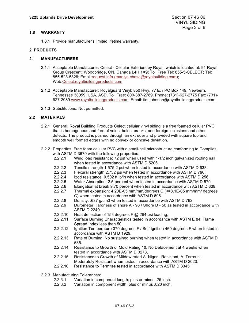
3225 Uplands Drive Development Section 07 46 06 VINYL SIDING Page 1 of 6
07 46 06-1
1 GENERAL
1.1 SECTION INCLUDES
1.1.1 Cellular PVC siding.
1.1.2 Cellular PVC trim and accessories.
1.2 RELATED SECTIONS
1.2.1 Section 06 10 11 - Rough Carpentry.
1.2.2 Section 07 21 13 – Board Insulation.
1.2.3 Section 07 92 10 - Joint Sealers.
1.3 REFERENCES
1.3.1 ASTM D 256 - Test Method for Determining the Pendulum Impact Resistance of Notched Specimens of Plastics.
1.3.2 ASTM D 570 - Water Absorption of Plastics.
1.3.3 ASTM D 635 - Test Method for Rate of Burning and/or Extent and Time of Burning of Self-Supported Plastics in a Horizontal Position.
1.3.4 ASTM D 638 - Test Method for Tensile Properties of Plastics.
1.3.5 ASTM D 648 - Standard Test Method for Deflection Temperature of Plastics Under Flexural Load in the Edgewise Position.
1.3.6 ASTM D 696 - Test Method for Coefficient of Linear Expansion of Plastics.
1.3.7 ASTM D 790 - Flexural Properties of Unreinforced and Reinforced Plastics and Electrical Insulating Materials.
1.3.8 ASTM D 792 - Standard Test Methods for Density and Specific Gravity (Relative Density) of Plastics by Displacement
1.3.9 ASTM D 1929 - Standard Test Method for Determining Ignition Temperature of Plastics.
1.3.10 ASTM D 2240 - Standard Test Method For Rubber Property - Durometer Hardness.
1.3.11 ASTM D 3273 - Standard Test Method for Resistance to Growth of Mold on the Surface of Interior Coatings in an Environmental Chamber.
1.3.12 ASTM D 3345 - Standard Test Method for Laboratory Evaluation of Wood and Other Cellulosic Materials for Resistance to Termites.
1.3.13 ASTM D 3679 - Specification for Rigid Poly Vinyl Chloride (PVC) Siding.
1.3.14 ASTM D 3960 - Standard Practice for Determining Volatile Organic Compound (VOC) Content of Paints and Related Coatings.
1.3.15 ASTM D 4226 - Test Methods for Impact Resistance of Rigid Poly Vinyl Chloride (PVC) Building Products.
Section 07 46 06 3225 Uplands Drive Development VINYL SIDING Page 2 of 6
1.3.16 ASTM D 5206 - Standard Test Method for Windload Resistance of Rigid Plastic Siding
1.3.17 ASTM E 84 - Test Method for Surface Burning Characteristics of Building Materials.
1.4.1 Submit under provisions of Section 01 33 00 – Submittal Procedures.
1.4.2 Product Data: Manufacturer's data sheets on each product to be used, including: 1.4.2.1 Preparation instructions and recommendations. 1.4.2.2 Storage and handling requirements and recommendations. 1.4.2.3 Installation methods.
1.4.3 Verification Samples: For each finish product specified, two samples, minimum size 6 inches (150 mm) square, representing actual product, color, and patterns.
1.4.4 Manufacturer's Certificates: Certify products meet or exceed specified requirements.
1.4.5 Closeout Submittals: Provide manufacturer's maintenance instructions that include recommendations for periodic cleaning and maintenance.
1.5 QUALITY ASSURANCE
1.5.1 Manufacturer Qualifications: A minimum of 10 years in the manufacture of PVC products. Maintain rigorous production quality control standards to ensure that cellular siding will perform as expected for its intended use.
1.5.2 Installer Qualifications: Installer with not less than two years documented experience with the installation of products similar to those specified.
1.5.3 Mock-Up: Provide a mock-up for evaluation of surface installation techniques and workmanship. 1.5.3.1 Finish areas designated by Architect. 1.5.3.2 Do not proceed with remaining work until workmanship, color, and sheen are
approved by Architect. 1.5.3.3 Reinstall mock-up area as required to produce acceptable work.
1.6 DELIVERY, STORAGE, AND HANDLING
1.6.1 Store products in manufacturer's unopened packaging until ready for installation.
1.6.2 Pack siding and trim with manufacturer's name, siding style, color, and identifying lot number.
1.6.3 Store siding, trim and accessories in clean, dry area, out of direct sunlight.
1.6.4 Handle material to prevent damage.
1.7 PROJECT CONDITIONS
1.7.1 Maintain environmental conditions (temperature, humidity, and ventilation within limits recommended by manufacturer for optimum results. Do not install products under environmental conditions outside manufacturer's absolute limits.
3225 Uplands Drive Development Section 07 46 06 VINYL SIDING Page 3 of 6
07 46 06-3
1.8 WARRANTY
1.8.1 Provide manufacturer's limited lifetime warranty.
2 PRODUCTS
2.1 MANUFACTURERS
2.1.1 Acceptable Manufacturer: Celect - Cellular Exteriors by Royal, which is located at: 91 Royal Group Crescent; Woodbridge, ON, Canada L4H 1X9; Toll Free Tel: 855-5-CELECT; Tel: 855-523-5328; Email:request info ([email protected]); Web:Celect.royalbuildingproducts.com
2.1.2 Acceptable Manufacturer; Royalguard Vinyl; 850 Hwy. 77 E. / PO Box 149, Newbern, Tennessee 38059, USA. ASD. Toll Free: 800-387-2789. Phone: (731)-627-2775 Fax: (731)-627-2989.www.royalbuildingproducts.com. Email: [email protected].
2.1.3 Substitutions: Not permitted.
2.2 MATERIALS
2.2.1 General: Royal Building Products Celect cellular vinyl siding is a free foamed cellular PVC that is homogenous and free of voids, holes, cracks, and foreign inclusions and other defects. The product is pushed through an extruder and provided with square top and smooth well formed edges with no convex or concave deviation.
2.2.2 Properties: Free foam cellular PVC with a small-cell microstructure conforming to Complies with ASTM D 3679 with the following properties. 2.2.2.1 Wind load resistance: 72 psf when used with 1-1/2 inch galvanized roofing nail
when tested in accordance with ASTM D 5206. 2.2.2.2 Tensile strength 1,575.2 psi when tested in accordance with ASTM D 638. 2.2.2.3 Flexural strength 2,732 psi when tested in accordance with ASTM D 790. 2.2.2.4 Izod resistance: 0.502 ft lb/in when tested in accordance with ASTM D 256. 2.2.2.5 Water Absorption: 2.5 percent when tested in accordance with ASTM D 570. 2.2.2.6 Elongation at break 9.70 percent when tested in accordance with ASTM D 638. 2.2.2.7 Thermal expansion: 4.23E-05 mm/mm/degrees C (<=8.1E-05 mm/mm/ degrees
C) when tested in accordance with ASTM D 696. 2.2.2.8 Density: .637 g/cm3 when tested in accordance with ASTM D 792. 2.2.2.9 Durometer Hardness of shore A - 96 / Shore D - 50 as tested in accordance with
ASTM D 2240. 2.2.2.10 Heat deflection of 153 degrees F @ 264 psi loading, 2.2.2.11 Surface Burning Characteristics tested in accordance with ASTM E 84: Flame
Spread Index less than 50. 2.2.2.12 Ignition Temperature 370 degrees F / Self Ignition 460 degrees F when tested in
accordance with ASTM D 1929. 2.2.2.13 Rate of Burning: No sustained burning when tested in accordance with ASTM D
635. 2.2.2.14 Resistance to Growth of Mold Rating 10. No Defacement at 4 weeks when
tested in accordance with ASTM D 3273. 2.2.2.15 Resistance to Growth of Mildew rated A. Niger - Resistant, A. Terreus -
Moderately Resistant when tested in accordance with ASTM D 2020. 2.2.2.16 Resistance to Termites tested in accordance with ASTM D 3345
2.2.3 Manufacturing Tolerances: 2.2.3.1 Variation in component length: plus or minus .25 inch. 2.2.3.2 Variation in component width: plus or minus .020 inch.
Section 07 46 06 3225 Uplands Drive Development VINYL SIDING Page 4 of 6
2.3 SIDING
2.3.1 Cellular Vinyl Siding: Celect Cellular Siding, single 8.468 inch (215 mm) interlocking traditional clapboard profile. Complies with ASTM D 3679. 2.3.1.1 Profile: 8.468 inch (215 mm) clapboard profile. 2.3.1.2 Interlocking Profile. 2.3.1.3 Length: 12 feet 4 inches (3.76 m). 2.3.1.4 Thickness: 0.358 inch (9.1 mm). 2.3.1.5 Finish: Textured. 2.3.1.6 Color shall be as follows:
2.3.1.6.1 Standard Colors: 2.3.1.6.1.1 Wrought Iron.
2.4 TRIM
2.4.1 Cellular Window and Door Surround Trim: Cellular Window and Door Surround Trim. 2.4.1.1 Length: 18 feet (5.48 m). 2.4.1.2 Width: 3.500 inch (88.90 mm). 2.4.1.3 Thickness: 0.625 inch (15.88 mm). 2.4.1.4 Finish: Smooth. 2.4.1.5 Color shall be as follows:
2.4.1.5.1 Standard Colors: 2.4.1.5.1.1 Wrought Iron.
2.4.2 Cellular Inside Corner Trim: Celect Cellular Inside Corner Trim. 2.4.2.1 Length: 10 feet (3.05 m). 2.4.2.2 Width: 2 inch (50.8 mm) / 2 inch (50.8 mm). 2.4.2.3 Thickness: 0.625 inch (15.88 mm). 2.4.2.4 Finish: Smooth. 2.4.2.5 Color shall be as follows:
2.4.2.5.1 Standard Colors: 2.4.2.5.1.1 Wrought Iron.
2.4.3 Cellular Outside Corner Trim: Celect Cellular Outside Corner Trim. 2.4.3.1 Length: 10 feet (3.05 m) and 20 feet (6.10 m). 2.4.3.2 Width: 5.500 inch (139.70 mm) / 5.500 inch (139.70 mm). 2.4.3.3 Thickness: 0.625 inch (15.88 mm). 2.4.3.4 Finish: Smooth. 2.4.3.5 Color shall be as follows:
2.4.3.5.1 Standard Colors: 2.4.3.5.1.1 Wrought Iron.
2.5 ACCESSORIES
2.5.1 Fasteners: Siding: 2.5.1.1 Corrosion-resistant 11 gauge roofing or ring shank nails (stainless steel or hot
dipped galvanized) with a minimum head diameter of 3/8 inch (9.5 m). Fasteners shall be long enough to penetrate a solid wood substrate a minimum of 1 inch (25.4 mm).
2.5.1.2 Use one fasteners every 16 inches (406 mm) on center. 2.5.1.3 Fasten to a flat, solid substrate. Do not fasten to hollow or uneven areas without
backing. 2.5.1.4 Pre-drilling is not required unless material is being installed in low temperatures.
2.5.2 Fasteners: Trim 2.5.2.1 Use fasteners designed for wood trim with thinner shank, blunt head, full round
3225 Uplands Drive Development Section 07 46 06 VINYL SIDING Page 5 of 6
07 46 06-5
head. Use only fasteners intended for exterior use such as stainless steel or hot dipped galvanized. Finish nails are also acceptable. All fasteners must be long enough to penetrate at least 1-1/2 inch (38 mm) into a solid nail-able surface.
2.5.2.2 Fasteners must be installed no closer than 2 inches (51 mm) from the end of each board
2.5.3 Adhesives: 2.5.3.1 Glue all trim joints (scarf or miter) with an approved exterior cellular PVC trim
adhesive. 2.5.3.2 Glue joints should be fastened on each side of the joint to allow adequate
bonding time. 2.5.3.3 Surfaces to be glued should be smooth, clean and in complete contact with each
other.
2.5.4 Sealants: 2.5.4.1 Use color matched urethane, polyurethane or acrylic based sealants without
silicone or oil/petroleum based components. Fill trim nail holes and joints with sealant as needed.
3 EXECUTION
3.1 EXAMINATION
3.1.1 Do not begin installation until substrates have been properly prepared.
3.1.2 Confirm that all critical dimensions are as specified on the drawings.
3.1.3 If substrate preparation is the responsibility of another installer, notify Architect of unsatisfactory preparation before proceeding.
3.2 PREPARATION
3.2.1 Clean surfaces thoroughly prior to installation.
3.2.2 Repair substrate flaws or defects before applying siding or trim.
3.2.3 Where necessary, fur surfaces to an even plane and free from obstructions before application.
3.2.4 Prepare surfaces using the methods recommended by the manufacturer for achieving the best result for the substrate under the project conditions.
3.3 INSTALLATION
3.3.1 Install siding and trim in accordance with the latest edition of the manufacturer's Installation Instructions.
3.3.2 Install cellular siding, trim and accessories in accordance with best practice, with all joint members plumb and true.
3.3.3 Securely attach siding using methods and materials recommended by siding manufacturer for wind load conditions at project site.
3.3.4 Install siding and accessories with all joint members plumb and true.
3.4 FIELD QUALITY CONTROL
3.4.1 After installation of siding and trim, check entire surface for obvious flaws or defects.
Section 07 46 06 3225 Uplands Drive Development VINYL SIDING Page 6 of 6
3.4.2 Replace and repair any problem areas.
3.5 CLEANING
3.5.1 After application of siding and trim, clean as necessary to remove all fingerprints and soiled areas.
3.5.2 Upon completion of siding application, clean entire area, removing all scrap, packaging, and unused materials related to this work.
3.6 PROTECTION
3.6.1 Protect installed products until completion of project.
3.6.2 Touch-up, repair or replace damaged products before Substantial Completion.
END OF SECTION
3225 Uplands Drive Development Section 07 52 00 MODIFIED BITUMINOUS MEMBRANE ROOFING Page 1 of 9
Part 1 General
1.1 SECTION INCLUDES
.1 Materials, preparation and application for caulking and sealants.
1.2 RELATED SECTIONS
.1 Section 06 10 11 - Rough Carpentry - Short Form
.2 Section 07 62 00 – Sheet Metal Flashing and Trim.
1.3 REFERENCES
.1 American Society for Testing and Materials International, (ASTM)
.1 ASTM C 1396/C 1396M-14A, Standard Specification for Gypsum Board.
.2 ASTM D 41/D41M-11, Standard Specification for Asphalt Primer Used in Roofing, Damp proofing, and Waterproofing.
.3 ASTM D 6164/D6164M-11, Standard Specification for Styrene Butadiene Styrene (SBS) Modified Bituminous Sheet Materials Using Polyester Reinforcements.
.2 Canadian General Standards Board (CGSB)
.1 CGSB 37-GP-9MA, Primer, Asphalt, Unfilled, for Asphalt Roofing, Dampproofing and Waterproofing.
.2 CGSB 37-GP-56M, Membrane, Modified, Bituminous, Prefabricated, and Reinforced for Roofing
.3 Canadian Roofing Contractors Association (CRCA)
.1 CAN/CSA-A123.4-04 (R2013), Asphalt for Constructing Built-Up Roof Coverings and Waterproofing Systems.
.4 Canadian Standards Association (CSA International)
.1 CAN/CSA-A123.4-04 (R2013), Asphalt for Constructing Built-Up Roof Coverings and Waterproofing Systems.
.5 Factory Mutual (FM Global)
.1 FM Approvals - Roofing Products.
.6 Health Canada/Workplace Hazardous Materials Information System (WHMIS)
.1 Material Safety Data Sheets (MSDS).
.7 Underwriters Laboratories' of Canada (ULC)
.1 CAN/ULC-S701-11, Standard for Thermal Insulation, Polystyrene, Boards and Pipe Covering.
.2 CAN/ULC-S702-14, Standard for Mineral Fibre Thermal Insulation for Buildings.
Section 07 52 00 3225 Uplands Drive Development MODIFIED BITUMINOUS MEMBRANE ROOFING Page 2 of 9
.3 CAN/ULC-S704-11, Standard for Thermal Insulation, Polyurethane and Polyisocyanurate Boards, Faced.
.4 CAN/ULC-S706-09, Standard for Wood Fibre Thermal Insulation for Buildings.
1.4 ADMINISTRATIVE REQUIREMENTS
.1 Convene pre-installation meeting one (1) week prior to beginning waterproofing Work, with roofing contractor's representative, Consultant and Client’s Representative..
1.5 ACTION AND INFORMATIONAL SUBMITTALS
.1 Provide submittals to Consultant in digital (PDF) format.
.2 Product Data:
.1 Provide two copies of most recent technical roofing components data sheets describing materials' physical properties and include product characteristics, performance criteria, physical size, finish and limitations.
.2 Provide two copies of WHMIS MSDS, and indicate VOC content for: .1 Primers. .2 Asphalt. .3 Sealers. .4 Filter fabric.
.3 Test and Evaluation Reports: submit laboratory test reports certifying compliance of bitumens and roofing membrane with specification requirements
.4 Submit Shop Drawings as required showing method of installation and layout of each layer, roof edge condition details, roof penetration flashing details, control and expansion joint details, standard roof sections, and other details required for proper roof system installation not specified in, or are different from Specifications and Drawings.
1.6 QUALITY ASSURANCE
.1 Installer qualifications: company or person specializing in application of modified bituminous roofing systems with 5 years documented experience approved by manufacturer.
.2 Provide inspection report from manufacturers Representative confirming that all aspects of modified bituminous membrane system are installed according to manufacturers recommendations and meet warranty regalements.
1.7 FIRE PROTECTION
.1 Fire Extinguishers:
.1 Maintain one cartridge operated type with hose and shut-off nozzle,
.2 ULC labelled for A, B and C class protection.
.3 Size 9kg on roof per torch applicator, within 3m of torch applicator.
.2 Maintain fire watch for 1 hour after each day's roofing operations cease.
3225 Uplands Drive Development Section 07 52 00 MODIFIED BITUMINOUS MEMBRANE ROOFING Page 3 of 9
1.8 DELIVERY, STORAGE, AND HANDLING
.1 Deliver, store and handle materials in accordance with manufacturer's written instructions.
.2 Storage and Handling Requirements:
.1 Safety: comply with requirements of Workplace Hazardous Materials Information System (WHMIS) regarding use, handling, storage, and disposal of asphalt, sealing compounds, primers and caulking materials.
.2 Provide and maintain dry, off-ground weatherproof storage.
.3 Store rolls of felt and membrane in upright position. Store membrane rolls with salvage edge up.
.4 Remove only in quantities required for same day use.
.5 Place plywood runways over completed Work to enable movement of material and other traffic.
.6 Store sealants at +5 degrees C minimum.
1.9 FIELD CONDITIONS
.1 Ambient Conditions
.1 Do not install roofing when temperature remains below -18 degrees C for torch application.
.2 Minimum temperature for solvent-based adhesive is -5 degrees C.
.2 Install roofing on dry deck, free of snow and ice, use only dry materials and apply only during weather that will not introduce moisture into roofing system.
1.10 WARRANTY
.1 For Work of this Section 07 52 00 - Modified Bituminous Membrane Roofing twelve (12) months warranty period is extended to sixty (60) months.
Part 2 Products
2.1 PERFORMANCE CRITERIA
.1 Compatibility between components of roofing system is essential. Provide written declaration to Client’s Representative stating that materials and components, as assembled in system, meet this requirement.
.2 Roofing System: to CSA A123.21 for wind uplift resistance.
Section 07 52 00 3225 Uplands Drive Development MODIFIED BITUMINOUS MEMBRANE ROOFING Page 4 of 9
2.2 DECK COVERING
.1 Base sheet mechanically fastened to plywood sheating with minimum pullout of 0.24kN for cap nails per fastener.
.2 Exterior Plywood Board Sheathing DFP: to CSA O121-M1978 Standard, 20.5 mm thick.
.3 Supply of wood sleepers, cant strips and other blocking: Section 06 10 11 Rough Carpentry.
2.3 DECK PRIMER
.1 Asphalt primer (where applicable): to CGSB 37-GP-9Ma.
.2 Asphalt primer (where applicable): to ASTM D312
2.4 VAPOUR RETARDER
.1 Field vapour retarder: to CGSB 37-GP-56M Styrene-Butadiene-Styrene (SBS) elastomeric polymer prefabricated sheet, polyester reinforcement, weighing 180 g/m².
.1 Top and bottom surfaces: polyethylene/self-adhering
2.5 MEMBRANE
.1 Base sheet: to CGSB 37-GP-56M
.1 Styrene-Butadiene-Styrene (SBS) elastomeric polymer prefabricated sheet, polyester reinforcement, having nominal weight of 180 g/m².
.2 Type 1
.3 Class C - plain surfaced.
.4 Grade 1 - standard service.
.5 Top and bottom surfaces: .1 polyethylene/polyethylene
.6 Base sheet membrane properties: to CGSB 37-GP-56M .1 Strain energy (longitudinal/transversal): 9.0/7.0kN/m. .2 Breaking strength (longitudinal/transversal):17.0/12.5 N/5 cm. .3 Ultimate elongation (longitudinal/transversal): 60/65%. .4 Tear resistance: 60 N. .5 Cold bending at -30 degrees C : no cracking. .6 Softening point: 110 degrees C. .7 Static puncture resistance: > 400. .8 Dimensional Stability: -0.3 / 0.3%.
.7 ULC certification: Class A
.2 Cap sheet membrane: to CGSB 37-GP-56M
3225 Uplands Drive Development Section 07 52 00 MODIFIED BITUMINOUS MEMBRANE ROOFING Page 5 of 9
.1 Styrene-Butadiene-Styrene(SBS) elastomeric polymer, prefabricated sheet, polyester reinforcement, having nominal weight of 250g/m².
.2 Type 1
.3 Class A-granule surfaced .1 Colour for granular surface: white
.4 Grade: heavy duty service.
.5 Bottom surface polyethylene
.6 Cap sheet membrane properties: to CGSB 37-GP-56M .1 Strain energy (longitudinal/transversal): 10.0/10.0kN/m. .2 Breaking strength (longitudinal/transversal): 18.0/16.0kN/m. .3 Ultimate elongation (longitudinal/transversal): 60/65%. .4 Tear resistance: 75 N. .5 Cold bending at -30 degrees C: No cracking. .6 Softening point: 110 degrees C. .7 Static puncture resistance: > 420. .8 Dimensional Stability: -0.8 / -0.2 %.
.7 ULC certification: Class A.
2.6 ADHESIVE
.1 Adhesive for securing overlay board and insulation: two component unit, consisting of two liquids mixed on site in container at time of application to produce a low-rise, two-part urethane adhesive.
2.7 OVERLAY BOARD
.1 Overlay Board: 3 mm thick asphalt based recovery board with non-woven glass facers, as recommended by the membrane manufacturer.
.1 Install over insulation to provide torch safe surface.
2.8 POLYISOCYANURATE INSULATION
.1 Not used.
2.9 SEALERS
.1 Plastic cement: asphalt.
.2 Sealing compound: rubber asphalt type
2.10 WALKWAYS
.1 Walkways to consist of one additional ply of cap sheet membrane. Colour to be different from field membrane as selected by Consultant.
2.11 CARPENTRY
.1 Refer to Section 06 10 11 - Rough Carpentry - Short Form.
Section 07 52 00 3225 Uplands Drive Development MODIFIED BITUMINOUS MEMBRANE ROOFING Page 6 of 9
2.12 FASTENERS
.1 Covering to wood deck: 24mm cap head, cadmium plated nails. Spaced minimum 228 mm o.c. Approved nail and plate assemblies.
Part 3 Execution
3.1 QUALITY OF WORK
.1 Do examination, preparation and roofing Work in accordance with Roofing Manufacturer's Specification Manual and CRCA Roofing Specification Manual, particularly for fire safety precautions.
.2 Do priming in accordance with manufacturers written recommendations.
.3 The interface of the walls and roof assemblies will be fitted with durable rigid material plywood providing connection point for continuity of air barrier.
.4 Fasten nails and caps with manufacturers written recommendations.
3.2 EXAMINATION OF ROOF DECKS
.1 Verification of Conditions:
.1 Inspect with Consultant and Client’s Representative conditions including parapets, construction joints, roof drains, plumbing vents and ventilation outlets to determine readiness to proceed.
.2 Evaluation and Assessment:
.1 Prior to beginning of work ensure: .1 Decks are firm, straight, smooth, dry, free of snow, ice or frost, and
swept clean of dust and debris. Do not use calcium or salt for ice or snow removal.
.2 Curbs have been built.
.3 Roof drains have been installed at proper elevations relative to finished roof surface.
.4 Plywood and lumber nailer plates have been installed to deck, walls and parapets as indicated.
.3 Do not install roofing materials during rain or snowfall.
3.3 PROTECTION OF IN-PLACE CONDITIONS
.1 Cover walls, walks and adjacent work where materials hoisted or used.
.2 Use warning signs and barriers. Maintain in good order until completion of Work.
.3 Clean off drips and smears of bituminous material immediately.
.4 Dispose of rain water off roof and away from face of building until roof drains or hoppers installed and connected.
3225 Uplands Drive Development Section 07 52 00 MODIFIED BITUMINOUS MEMBRANE ROOFING Page 7 of 9
.5 Protect roof from traffic and damage. Comply with precautions deemed necessary by Client’s Representative.
.6 At end of each day's work or when stoppage occurs due to inclement weather, provide protection for completed Work and materials out of storage.
.7 Metal connectors and decking will be treated with rust proofing or galvanization.
3.4 DECK SHEATHING
.1 Mechanically fasten each board to raised sleepers at 400 mm o.c. with 12d galvanized nails. Mechanically fasten wood sleepers to main plywood deck and wood trusses at 400 mm o.c. with 16d galvanized nails.
.2 Place with long axis of each sheet perpendicular to framing member.
.1 Adhere insulation to vapour barrier using solvent-free urethane adhesive.
.2 Place boards in parallel rows with ends staggered, and in firm contact with one another.
.3 Cut end pieces to suit.
.4 Apply adhesive as per manufacture recommendations.
.5 Separate the membrane and insulation with a drainage layer or slipsheet.
.2 Tapered insulation application:
.1 adhere insulation to base insulation as per manufacture recommendations.
.2 Install tapered insulation as second insulation layer, in accordance with shop drawings. Stagger joints between layers 150 mm minimum.
.3 Overlay Board: adhesive application:
.1 Adhere overlay board to insulation using solvent-free urethane adhesive.
.2 Place boards in parallel rows with end joints staggered. All boards to be butted against the next, not overlaps.
.3 Apply adhesive as per manufacture recommendations.
.4 Base sheet application:
Section 07 52 00 3225 Uplands Drive Development MODIFIED BITUMINOUS MEMBRANE ROOFING Page 8 of 9
.1 Starting at low point of roof, perpendicular to slope, unroll base sheet, align and reroll from both ends.
.2 Unroll and torch base sheet onto substrate taking care not to burn membrane or its reinforcement or substrate.
.3 Lap sheets 75 mm minimum for side and 150 mm minimum for end laps.
.4 Application to be free of blisters, wrinkles and fishmouths.
.5 Cap sheet application:
.1 Starting at low point on roof, perpendicular to slope, unroll cap sheet, align and reroll from both ends.
.2 Unroll and torch cap sheet onto base sheet taking care not to burn membrane or its reinforcement.
.3 Lap sheets 75 mm minimum for side laps and 150 mm minimum for end laps. Offset joints in cap sheet 300 mm minimum from those in base sheet.
.4 Application to be free of blisters, fishmouths and wrinkles.
.5 Do membrane application in accordance with manufacturer's recommendations.
.6 Flashings:
.1 Complete installation of flashing base sheet stripping prior to installing membrane cap sheet.
.2 Torch base and cap sheet onto substrate in 1 metre wide strips.
.3 Lap flashing base sheet to membrane base sheet minimum 150 mm and seal by torch welding.
.4 Lap flashing cap sheet to membrane cap sheet 250 mm minimum and torch weld.
.5 Provide 75 mm minimum side lap and seal.
.6 Properly secure flashings to their support, without sags, blisters, fishmouths or wrinkles.
.7 Do work in accordance with manufacturer's recommendations.
.7 Roof penetrations:
.1 Install roof drain pans, vent stack covers and other roof penetration flashings and seal to membrane in accordance with manufacturer's recommendations and details.
3.8 WALKWAYS
.1 Install walkway membrane in accordance with manufacturer's instructions and as indicated.
.1 Apply primer to cap sheet membrane and torch-apply, ensuring selvage edge is removed.
3.9 FIELD QUALITY CONTROL
.1 Inspections:
.1 Inspection and testing of roofing application to be carried out by recognized testing laboratory.
.2 Contractor to pay for tests.
3225 Uplands Drive Development Section 07 52 00 MODIFIED BITUMINOUS MEMBRANE ROOFING Page 9 of 9
3.10 CLEANING
.1 Remove bituminous markings from finished surfaces.
.2 In areas where finished surfaces are soiled caused by work of this section, consult manufacturer of surfaces for cleaning advice and complying with their documented instructions.
.3 Repair or replace defaced or disfigured finishes caused by work of this section.
END OF SECTION
3225 Uplands Drive Development Section 07 61 00 SHEET METAL ROOFING Page 1 of 11
□
Part 1 General
1.1 SECTION INCLUDES
.1 Materials and installation for sheet metal roofing.
.1 AA DAF-45-[R03], Designation System for Aluminum Finishes - 9th Edition.
.2 AA ASM-35-[October 2000], Specifications for Aluminum Sheet Metal Work in Building Construction, Section 5.
.2 American Society for Testing and Materials International, (ASTM).
.1 ASTM A167-[99], Specification for Stainless and Heat-Resisting Chromium-Nickel Steel Plate, Sheet, and Strip.
.2 ASTM A240/A240M-[02a], Standard Specification for Chromium and Chromium-Nickel Stainless Steel Plate, Sheet, and Strip for Pressure Vessels and for General Applications.
.3 ASTM A653/A653M-[02a], Standard Specification for Steel Sheet, Zinc-Coated (Galvanized) or Zinc-Iron Alloy-Coated (Galvannealed) by the Hot-Dip Process.
.4 ASTM A792/A792M-[02], Standard Specification for Steel Sheet, 55% Aluminum-Zinc Alloy-Coated by the Hot Dip Process.
.5 ASTM B32-[00e1], Standard Specification for Solder Metal.
.6 ASTM B370-[98], Standard Specification for Copper Sheet and Strip for Building Construction.
.7 ASTM D523-[89(1999)], Standard Test Method for Specular Gloss.
.8 ASTM D822-[01], Standard Practice for Filtered Open-Flame Carbon-Arc Exposures of Paint and Related Coatings.
.1 Canadian Environmental Protection Act (CEPA), 1999.
.6 Health Canada/Workplace Hazardous Materials Information System (WHMIS).
.1 Material Safety Data Sheets (MSDS).
.7 National Research Council Canada (NRC)/Institute for Research in Construction (IRC) - Canadian Construction Materials Centre (CCMC).
.1 CCMC-[2002], Registry of Product Evaluations.
.8 Transport Canada (TC).
.1 Transportation of Dangerous Goods Act (TDGA), 1992.
1.4 SUBMITTALS
.1 Submit proof of manufacturer's CCMC Listing and listing number to Consultant.
.2 Manufacturer's Instructions: Provide to indicate special handling criteria, installation sequence, and cleaning procedures.
.3 Submit product data in accordance with Section 01 33 00 - Submittal Procedures.
.4 Submit product data sheets for roofing felts. Include:
.1 Product characteristics.
.2 Performance criteria.
.3 Limitations.
.5 Submit shop drawings in accordance with Section 01 33 00 - Submittal Procedures.
.6 Indicate arrangements of sheets and joints, types and locations of fasteners and special shapes and relationship of panels to structural frame.
.7 Submit samples in accordance with Section 01 33 00 - Submittal Procedures.
.8 Submit 300 x 300 mm samples of each sheet metal material.
1.5 QUALITY ASSURANCE
.1 Submit mock-ups in accordance with Section 01 45 00 - Quality Control.
.2 Fabricate 300 x 300 mm sample roofing panel using identical project materials and methods to include typical seam.
.3 Mock-up will be used:
.1 To judge workmanship, substrate preparation, operation of equipment and material application.
.4 Locate where directed.
3225 Uplands Drive Development Section 07 61 00 SHEET METAL ROOFING Page 3 of 11
□
.5 Allow 48 hours for inspection of mock-up by Consultant and Owner before proceeding with sheet metal flashing work.
.6 When accepted, mock-up will demonstrate minimum standard of quality required for this Work. Approved mock-up may remain as part of finished Work.
1.6 WASTE MANAGEMENT AND DISPOSAL
.1 Separate waste materials for recycling in accordance with Section 01 74 19 - Construction/Demolition Waste Management And Disposal.
.2 Remove from site and dispose of packaging materials at appropriate recycling facilities.
.3 Divert unused metal materials from landfill to metal recycling facility as approved by Consultant.
.4 Unused paint, caulking, and sealing compound materials must be disposed of at an official hazardous material collections site as approved Consultant.
.5 Unused paint, caulking, and sealing compound materials must not be disposed of into sewer system, into streams, lakes, onto ground or in other location where it will pose health or environmental hazard.
.6 Fold up metal banding, flatten and place in designated area for recycling.
Part 2 Products
2.1 SHEET METAL MATERIALS
.1 Aluminum-zinc alloy coated steel sheet: to ASTM A792/A792M, ASTM-A792 SS, commercial quality, grade 33, with AZ180 coating, extra smooth surface, 24 Gauge (0.026”) base metal thickness.
.2 Acceptable products (or approved equal):
.1 Ideal Roofing: Heritage (HF) profile, Series 10,000 (Kynar 500), Galvalume Plus, 16” (406 mm) standard width.
2.2 ACCESSORIES
.1 Underlay: dry sheathing to CAN/CGSB-51.32.
.2 Sealant: compatible with systems materials, and as recommended by system manufacturer.
.3 Fasteners: concealed.
.4 Washers: of same material as sheet metal, 1 mm thick with rubber packings.
.5 Snow Guards:
Section 07 61 00 3225 Uplands Drive Development SHEET METAL ROOFING Page 4 of 11
□
.1 Brakets: 2-hole bracket, 3.2mm (1/8”) thick Galvanized G-90 steel brackets, with two 32mm (1 ¼”) diameter holes inserted with a plastic protector. Each bracket shall include 8 screws (Galvanized) 14x2 HHA with neoprene washers.
.2 Bars: Galvanized G-90 steel tube 1.5mm (1/16”) thick x 25.4mm (1”) diameter x 1.21m (4’) long with a reduced 75mm (3”) ferrule 1.14m (45”) coverage.
Part 3 Execution
3.1 INSTALLATION
.1 Install sheet metal roof panels as per manufacturer’s recommendations.
.2 Use concealed fastenings except where approved by Consultant before installation.
.3 Provide underlay under sheet metal roofing. Secure in place and lap joints 100 mm minimum.
.4 Clean steel cladding at completion of work. Remove all debris from adjacent surfaces.
.5 Install accessories as per manufacturer’s recommendations.
END OF SECTION
3225 Uplands Drive Development Section 07 62 00 SHEET METAL FLASHING AND TRIM Page 1 of 4
.1 Aluminum Sheet Metal Work in Building Construction-2002.
.2 AA DAF45-2003, Designation System for Aluminum Finishes.
.2 American Society for Testing and Materials (ASTM International)
.1 ASTM A167-99 (2009), Specification for Stainless and Heat-Resisting Chromium-Nickel Steel Plate, Sheet, and Strip.
.2 ASTM A240/A240M-11b, Standard Specification for Chromium and Chromium-Nickel Stainless Steel Plate, Sheet, and Strip for Pressure Vessels and for General Applications.
.3 ASTM A606-09a, Standard Specification for Steel, Sheet and Strip, High-Strength, Low-Alloy, Hot-Rolled and Cold-Rolled, with Improved Atmospheric Corrosion Resistance.
.4 ASTM A653/A653M-11, Standard Specification for Steel Sheet, Zinc-Coated (Galvanized) or Zinc-Iron Alloy-Coated (Galvannealed) by the Hot-Dip Process.
.5 ASTM A792/A792M-10, Standard Specification for Steel Sheet, 55% Aluminum-Zinc Alloy-Coated by the Hot-Dip Process.
.6 ASTM B32-08, Standard Specification for Solder Metal.
.7 ASTM B370-11, Standard Specification for Copper Sheet and Strip for Building Construction.
.8 ASTM D523-08, Standard Test Method for Specular Gloss.
.9 ASTM D822-01 (2006), Standard Practice for Filtered Open-Flame Carbon-Arc Exposures of Paint and Related Coatings.
.3 Canadian Roofing Contractors Association (CRCA)
.3 Underlay for metal flashing: dry sheathing to CAN/CGSB-51.32.
.4 Cleats: of same material, and temper as sheet metal, minimum 50 mm wide. Thickness same as sheet metal being secured.
.5 Fasteners: of same material as sheet metal, to CSA B111, flat head roofing nails of length and thickness suitable for metal flashing application.
.6 Washers: of same material as sheet metal, 1 mm thick with rubber packings.
.7 Solder: to ASTM B32.
.8 Flux: rosin, cut hydrochloric acid, or commercial preparation suitable for materials to be soldered.
.9 Touch-up paint: as recommended by prefinished material manufacturer.
3225 Uplands Drive Development Section 07 62 00 SHEET METAL FLASHING AND TRIM Page 3 of 4
2.4 FABRICATION
.1 Fabricate metal flashings and other sheet metal work as indicated.
.2 Fabricate galvanized flashings and other sheet aluminum work in accordance with AA-Aluminum Sheet Metal Work in Building Construction.
.3 Form pieces in 2400 mm maximum lengths. Make allowance for expansion at joints.
.4 Hem exposed edges on underside 12 mm. Mitre and seal corners with sealant.
.5 Form sections square, true and accurate to size, free from distortion and other defects detrimental to appearance or performance.
.6 Apply isolation coating to metal surfaces to be embedded in concrete or mortar.
.7 Cut galvanize with shears as automatic shears only. Do not use saws or guiders.
2.5 METAL FLASHINGS
.1 Form flashings, copings and fascias to profiles indicated of prefinished steel, prefinished aluminum or copper, as per construction documents
2.6 REGLETS AND CAP FLASHINGS
.1 Form recessed reglets metal cap flashing of sheet metal to be built-in masonry work for base flashings as detailed. Provide slotted fixing holes and steel/plastic washer fasteners. Cover face and ends with plastic tape.
2.7 SCUPPERS
.1 Form scuppers from galvanize sheet metal as per construction documents.
.2 Sizes and profiles as indicated.
.3 Provide necessary fastenings.
.4 Form 600 x 600 mm splash pans from prefinished steel or aluminum sheet metal.
2.8 ALUMINUM FINISHES
.1 Finish exposed surfaces of aluminum components in accordance with AA DAF45.
.1 Electrolytically deposited colour anodic finish: colour to match Consultant's sample.
.2 Appearance and properties of anodized finishes designated by the Aluminum Association as Architectural Class 1, Architectural Class 2, and Protective and Decorative shall meet requirements of CAN/CSA-A440/A440.1, for coating Classes 1, 2 and 3 respectively.
Section 07 62 00 3225 Uplands Drive Development SHEET METAL FLASHING AND TRIM Page 4 of 4
Part 3 Execution
3.1 INSTALLATION
.1 Install sheet metal work as detailed.
.2 Use concealed fastenings except where approved before installation.
.3 Provide underlay under sheet metal. Secure in place and lap joints 100 mm.
.4 Counterflash bituminous flashings at intersections of roof with vertical surfaces and curbs. Flash joints as detailed.
.5 Lock end joints and caulk with sealant.
.6 Turn top edge of flashing into recessed reglet or mortar joint minimum of 25 mm. Lead wedge flashing securely into joint.
.7 Caulk flashing at reglet with sealant.
.8 Install pans, where shown around items projecting through roof membrane.
3.2 SCUPPERS
.1 Install scuppers as indicated.
END OF SECTION
3225 Uplands Drive Development Section 07 84 00 FIRESTOPPING Page 1 of 5
Part 1 General
1.1 RELATED WORK
.1 Fire stopping and smoke seals within mechanical assemblies (i.e inside ducts, dampers) and electrical assemblies (i.e. inside cable trays) are specified in Division 15 and 16 respectively.
1.2 REFERENCES
.1 Underwriter’s Laboratories of Canada (ULC)
.1 ULC-S115-11, Fire Tests of Firestop Systems.
1.3 SAMPLES
.1 Submit samples to Consultant for approval.
.2 Submit duplicate 300 x 300 mm samples showing actual firestop material proposed for project.
1.4 QUALITY ASSURANCE
.1 Qualifications:
.1 Installer: company approved by manufacturer. Minimum five (5) years of proved experience with manufacturer’s product.
.2 Pre-Installation Meetings: convene pre-installation meeting one week prior to beginning work of this Section, with contractor's representative and Consultant to:
.1 Verify project requirements.
.2 Review installation and substrate conditions.
.3 Co-ordination with other building sub–trades.
.4 Review manufacturer's installation instructions and warranty requirements.
.3 Provide inspector report form fire stopping manufacturer representative to Consultant following installation of fire stopping
1.5 SHOP DRAWINGS
.1 Submit shop drawings in digital (PDF) format.
.2 Submit shop drawings to show proposed material, reinforcement, anchorage, fastenings and method of installation. Construction details should accurately reflect actual job conditions.
1.6 PRODUCT DATA
.1 Submit product data to Consultant.
Section 07 84 00 3225 Uplands Drive Development FIRESTOPPING Page 2 of 5
.2 Submit manufacturer's product data for materials and prefabricated devices, providing descriptions are sufficient for identification at job site. Include manufacturer's printed instructions for installation.
Part 2 Products
2.1 MATERIALS
.1 Fire stopping and smoke seal systems: in accordance with ULC-S115.
.1 Asbestos-free materials and systems capable of maintaining an effective barrier against flame, smoke and gases in compliance with requirements of ULC-S115 and not to exceed opening sizes for which they are intended and conforming to special requirements specified in Part 3
.2 Firestop system rating: in accordance with the Ontario Building Code.
.2 Service penetration assemblies: certified by ULC in accordance with ULC-S115 and listed in ULC Guide No.40 U19.
.3 Service penetration firestop components: certified by ULC in accordance with ULC-S115 and listed in ULC Guide No.40 U19.13 and ULC Guide No.40 U19.15 under the Label Service of ULC.
.4 Fire-resistance rating of installed fire stopping assembly in accordance with OBC.
.5 Fire stopping and smoke seals at openings intended for ease of re-entry such as cables: elastomeric seal.
.6 Fire stopping and smoke seals at openings around penetrations for pipes, ductwork and other mechanical items requiring sound and vibration control: elastomeric seal.
.7 Primers: to manufacturer's recommendation for specific material, substrate, and end use.
.8 Water (if applicable): potable, clean and free from injurious amounts of deleterious substances.
.9 Damming and backup materials, supports and anchoring devices: to manufacturer's recommendations, and in accordance with tested assembly being installed as acceptable to authorities having jurisdiction.
.10 Sealants for vertical joints: non-sagging.
.11 Sealants must have a VOC limit of less than 250 g/L, as per SCAQMD Rule 1168, October 2003. Provide MSDS sheet or other documentation indicating VOC content of sealant used.
.12 Acceptable manufacturers:
.1 Dow Corning Canada Inc.
.2 Tremco Ltd.
.3 Hilti (Canada) Corporation
3225 Uplands Drive Development Section 07 84 00 FIRESTOPPING Page 3 of 5
.4 3M Canada Inc.
.5 A/D Fire Protection Systems Inc.
.6 ProSet Systems by Firestop Strategies Ltd.
Part 3 Execution
3.1 MANUFACTURER'S INSTRUCTIONS
.1 Compliance: comply with manufacturer's written recommendations or specifications, including product technical bulletins, handling, storage and installation instructions, and datasheets.
3.2 PREPARATION
.1 Examine sizes and conditions of voids to be filled to establish correct thicknesses and installation of materials. Ensure that substrates and surfaces are clean, dry and frost free.
.2 Prepare surfaces in contact with fire stopping materials and smoke seals to manufacturer's instructions.
.3 Maintain insulation around pipes and ducts penetrating fire separation.
.4 Mask where necessary to avoid spillage and over coating onto adjoining surfaces; remove stains on adjacent surfaces.
3.3 INSTALLATION –GENERAL
.1 Install fire stopping and smoke seal material and components in accordance with ULC certification and manufacturer's instructions.
.2 Seal holes or voids made by through penetrations, poke-through termination devices, and un–penetrated openings or joints to ensure continuity and integrity of fire separation are maintained.
.3 Provide temporary forming as required and remove forming only after materials have gained sufficient strength and after initial curing.
.4 Tool or trowel exposed surfaces to a neat finish.
.5 Remove excess compound promptly as work progresses and upon completion.
3.4 INSTALLATION - FIRESTOPPING AND SMOKE SEAL AT TOP OF FIRE RATED GYPSUM BOARD PARTITIONS ABUTTING UNDERSIDE OF STRUCTURE
.1 Fill space with properly sized firestopping.
.2 Pack firestopping from both sides of partition.
.3 Butt each firestop section tightly against preceding section. Leave no voids.
Section 07 84 00 3225 Uplands Drive Development FIRESTOPPING Page 4 of 5
.4 Apply fire –rated sealant in accordance with manufacturer’s installation instructions.
3.5 INSTALLATION - MECHANICAL AND ELECTRICAL PENETRATION FIRESTOPPING AND SMOKE SEAL
.1 Apply firestopping and smoke seal to mechanical and electrical through penetrations.
.2 Apply fire rated sealant to unpenetrated openings and sleeves installed for future use through fire rated assemblies.
.3 Where necessary, remove insulation from insulated pipes and ducts where pipes or ducts penetrate a fire separation, unless ULC certified assembly permits such insulation to remain within the fire rated assembly.
3.6 INSPECTION
.1 Notify Consultant when ready for inspection and prior to concealing or enclosing firestopping materials and service penetration assemblies.
3.7 SCHEDULE
.1 Firestop and smoke seal at:
.1 Penetrations through fire-resistance rated masonry, concrete, and gypsum board partitions and walls.
.2 Edge of floor slabs at curtain wall and precast concrete panels.
.3 Top of fire-resistance rated masonry and gypsum board partitions.
.4 Intersection of fire-resistance rated masonry and gypsum board partitions.
.5 Control and sway joints in fire-resistance rated masonry and gypsum board partitions and walls.
.6 Penetrations through fire-resistance rated floor slabs, ceilings and roofs.
.7 Openings and sleeves installed for future use through fire separations.
.8 Around mechanical and electrical assemblies penetrating fire separations.
.9 Rigid ducts: greater than 129 cm2: fire stopping to consist of bead of fire stopping material between retaining angle and fire separation and between retaining angle and duct, on each side of fire separation.
3.8 FIELD QUALITY CONTROL
.1 Manufacturer's Field Services:
.1 Obtain written report from manufacturer verifying compliance of Work, in handling, installing, applying, protecting and cleaning of product and submit Manufacturer's Field Reports.
.2 Provide manufacturer's field services consisting of product use recommendations and periodic site visits for inspection of product installation in accordance with manufacturer's instructions.
.3 Schedule site visits, to review Work.
3225 Uplands Drive Development Section 07 84 00 FIRESTOPPING Page 5 of 5
3.9 CLEAN UP
.1 Remove excess materials and debris and clean adjacent surfaces immediately after application.
.2 Remove temporary dams after initial set of fire stopping and smoke seal materials.
END OF SECTION
3225 Uplands Drive Development Section 07 92 10 JOINT SEALING Page 1 of 7
Part 1 General
1.1 SECTION INCLUDES
.1 Materials, preparation and application for caulking and sealants.
1.2 RELATED SECTIONS
.1 Section 09 21 16 - Gypsum Board
1.3 REFERENCES
.1 American Society for Testing and Materials International, (ASTM)
.1 ASTM C919-12, Standard Practice for Use of Sealants in Acoustical Applications.
.2 Department of Justice Canada (Jus)
.1 Canadian Environmental Protection Act, 1999 (CEPA).
.3 Health Canada/Workplace Hazardous Materials Information System (WHMIS)
.1 Material Safety Data Sheets (MSDS).
.4 Transport Canada (TC)
.1 Transportation of Dangerous Goods Act, 1992 (TDGA).
1.4 SUBMITTALS
.1 Submit product data to Consultant in digital (PDF) format.
.2 Manufacturer's product to describe.
.1 Caulking compound.
.2 Primers.
.3 Sealing compound, each type, including compatibility when different sealants are in contact with each other.
.3 Submit samples to Consultant.
.4 Submit duplicate samples of each type of material and colour.
.5 Cured samples of exposed sealants for each color where required to match adjacent material.
.6 Submit manufacturer's instructions to Consultant in digital (PDF) format.
.1 Instructions to include installation instructions for each product used.
1.5 QUALITY ASSURANCE/MOCK-UP
.1 Construct mock-up for Consultant’s review.
Section 07 92 10 3225 Uplands Drive Development JOINT SEALING Page 2 of 7
.2 Construct mock-up to show location, size, shape and depth of joint complete with back-up material, primer, caulking and sealant.
.3 Mock-up will be used:
.1 To judge workmanship, substrate preparation, operation of equipment and material application.
.4 Locate where directed.
.5 Allow 24 hours for inspection of mock-up by Consultant before proceeding with sealant work.
.6 When accepted, mock-up will demonstrate minimum standard of quality required for this Work. Approved mock-up may remain as part of finished Work.
.7 Provide to consultant inspection report from manufacturers representative following complete installation.
1.6 DELIVERY, STORAGE, AND HANDLING
.1 Deliver, handle, store and protect materials in accordance with manufacturer’s recommendations.
.2 Deliver and store materials in original wrappings and containers with manufacturer's seals and labels, intact. Protect from freezing, moisture, water and contact with ground or floor.
1.7 PROJECT CONDITIONS
.1 Environmental Limitations:
.1 Do not proceed with installation of joint sealants under following conditions: .1 When ambient and substrate temperature conditions are outside limits
permitted by joint sealant manufacturer or are below 4.4 degrees C. .2 When joint substrates are wet.
.2 Joint-Width Conditions:
.1 Do not proceed with installation of joint sealants where joint widths are less than those allowed by joint sealant manufacturer for applications indicated.
.3 Joint-Substrate Conditions:
.1 Do not proceed with installation of joint sealants until contaminants capable of interfering with adhesion are removed from joint substrates.
1.8 ENVIRONMENTAL REQUIREMENTS
.1 Comply with requirements of Workplace Hazardous Materials Information System (WHMIS) regarding use, handling, storage, and disposal of hazardous materials; and regarding labelling and provision of Material Safety Data Sheets (MSDS) acceptable to Labour Canada.
3225 Uplands Drive Development Section 07 92 10 JOINT SEALING Page 3 of 7
.2 Conform to manufacturer's recommended temperatures, relative humidity, and substrate moisture content for application and curing of sealants including special conditions governing use.
.3 Ventilate area of work by use of approved portable supply and exhaust fans.
Part 2 Products
2.1 GENERAL
.1 Products and manufacturers specified establish performance and quality required and are not intended to restrict submission by other manufacturers.
.2 Acceptance of Products from other manufacturers will be subject to review by the Consultant, for conformity with the specifications and meeting the physical characteristics of the specified Products. Include compliance with referenced standards. Submittals which do not include adequate data for the product evaluation will not be considered.
.3 If unapproved substitute products are included in the bid, the specified Products shall be provided without additional compensation.
2.2 SEALANT MATERIALS
.1 Do not use caulking that emits strong odours, contains toxic chemicals or is not certified as mould resistant in air handling units.
.2 When low toxicity caulks are not possible, confine usage to areas which offgas to exterior, are contained behind air barriers, or are applied several months before occupancy to maximize offgas time.
.3 Where sealants are qualified with primers use only these primers.
.4 Sealants must have a VOC limit of less than 250 g/L, as per SCAQMD Rule 1168, October 2003.
2.3 SEALANT MATERIAL DESIGNATIONS
.1 TYPE 1 – Silicones One Part. (mildew resistant)
.1 To CAN/CGSB-19.13.
.2 Colour: translucent, white or clear as selected later by the Consultant unless otherwise specified, normally to match the predominant Products to which sealant is applied.
.3 Acceptable material: .1 Proglaze by Tremco Canada Limited. .2 Sonneborn Omniplus by Sonneborn Building Products, division of
ChemRex Inc. .3 Dow Corning 786 by Dow Corning Canada Inc. .4 GE Sanitary SCS1700 by GE Silicones Canada.
Section 07 92 10 3225 Uplands Drive Development JOINT SEALING Page 4 of 7
.5 CRL Mildew Resistant Translucent/White/Clear Silicone Sealant by C. R. Laurence Canada, Concord, Ontario.
.6 Or other Product and manufacturer acceptable to the Consultant.
.2 TYPE 2 – Acrylic Latex One Part.
.1 To CAN/CGSB-19.17.
.2 Colour: white or clear as selected later by the Consultant unless otherwise specified, normally to match the predominant Products to which sealant is applied.
.3 Acceptable material: .1 SPECTREM 1 by. Tremco Canada Limited. .2 Dow Corning 791 by Dow Corning Canada Inc. .3 GE RCS20 by GE Silicones Canada. .4 Or other Product and manufacturer acceptable to the Consultant.
.3 TYPE 3 – Acoustical Sealant.
.1 Foam sealant to ASTM C919.
.2 Flames Spread Rating: < 25, in accordance with CAN/ULC-S102.
.3 Smoke Development Classification: < 50, in accordance with CAN/ULC-S102.
.4 Acceptable material: .1 CF 810 Crack and Joint Sealant by Hilti Corporation. .2 Or other product and manufacturer acceptable to the Consultant.
.4 TYPE 4 – Acoustical Sealant, Paintable.
.1 To ASTM C834.
.2 Colour: white.
.3 Acceptable material: .1 Tremflex 834 by Tremco Ltd. .2 Or other Product and manufacturer acceptable to the Consultant.
.5 TYPE 5 – One Part Fire Resistant.
.1 To ASTM E814 and ASTM E1966 .
.2 Acceptable material: .1 Metacaulk MC 150+ by Rectorseal .2 Or other Product and manufacturer acceptable to the Consultant.
.6 TYPE 6 – Thermoplastic Rubber-based
.1 One component, thermoplastic rubber-based sealant to CAN/CGSB–19.13–M, Class MCG–2–25–B–N,
.2 Acceptable material: .1 Supraexpert by Mulco, .2 Sonoplastic NP1 by Sonneborn
.7 Preformed Compressible and Non-Compressible back-up materials.
.1 Polyethylene, Urethane, Neoprene or Vinyl Foam.
3225 Uplands Drive Development Section 07 92 10 JOINT SEALING Page 5 of 7
.1 Extruded closed cell foam backer rod.
.2 Size: oversize 30 to 50 %.
.3 Backing shall be compatible with sealant, primer and substrate. .2 Neoprene or Butyl Rubber.
.1 Round solid rod, Shore A hardness 70. .3 High Density Foam.
.1 Extruded closed cell polyvinyl chloride (PVC), extruded polyethylene, closed cell, Shore A hardness 20, tensile strength 140 to 200 kPa, extruded polyolefin foam, 32 kg/m3 density, or neoprene foam backer, size as recommended by manufacturer.
.4 Bond Breaker Tape. .1 Polyethylene bond breaker tape, which will not bond to sealant.
.5 Joint Primer. .1 Non-staining, suitable for substrate surfaces, compatible with joint
forming materials and as recommended by sealant manufacturer.
2.4 SEALANT SELECTION
.1 Perimeters of interior frames, as detailed and itemized: Sealant type: TYPE 1.
.2 Exposed interior control joints in drywall: Sealant type: TYPE 1.
.3 Acoustical Partitions as detailed and in accordance with Section 09 21 16 - Gypsum Board: Sealant Type 3: Acoustical for concealed applications.
.4 Acoustical Partitions as detailed and in accordance with Section 09 21 16 - Gypsum Board: Sealant Type 4: Acoustical for exposed applications.
.5 SR-1 and SR-2 Partitions as detailed and in accordance with Section 09 21 16 - Gypsum Board: Sealant TYPE 5: One Part Fire Resistant.
.6 Perimeters of exterior frames, as detailed and itemized: Sealant type: TYPE 6.
2.5 JOINT CLEANER
.1 Non-corrosive and non-staining type, compatible with joint forming materials and sealant recommended by sealant manufacturer.
.2 Primer: as recommended by manufacturer.
Part 3 Execution
3.1 PROTECTION
.1 Protect installed Work of other trades from staining or contamination.
Section 07 92 10 3225 Uplands Drive Development JOINT SEALING Page 6 of 7
3.2 SURFACE PREPARATION
.1 Examine joint sizes and conditions to establish correct depth to width relationship for installation of backup materials and sealants.
.2 Clean bonding joint surfaces of harmful matter substances including dust, rust, oil grease, and other matter, which may impair Work.
.3 Do not apply sealants to joint surfaces treated with sealer, curing compound, water repellent, or other coatings unless tests have been performed to ensure compatibility of materials. Remove coatings as required.
.4 Ensure joint surfaces are dry and frost free.
.5 Prepare surfaces in accordance with manufacturer's directions.
3.3 PRIMING
.1 Where necessary to prevent staining, mask adjacent surfaces prior to priming and caulking.
.2 Prime sides of joints in accordance with sealant manufacturer's instructions immediately prior to caulking.
3.4 BACKUP MATERIAL
.1 Apply bond breaker tape where required to manufacturer's instructions.
.2 Install joint filler to achieve correct joint depth and shape, with approximately 30% compression.
3.5 MIXING
.1 Mix materials in strict accordance with sealant manufacturer's instructions.
3.6 APPLICATION
.1 Sealant.
.1 Apply sealant in accordance with manufacturer's written instructions.
.2 Mask edges of joint where irregular surface or sensitive joint border exists to provide neat joint.
.3 Apply sealant in continuous beads.
.4 Apply sealant using gun with proper size nozzle.
.5 Use sufficient pressure to fill voids and joints solid.
.6 Form surface of sealant with full bead, smooth, free from ridges, wrinkles, sags, air pockets, embedded impurities.
.7 Tool exposed surfaces before skinning begins to give slightly concave shape.
.8 Remove excess compound promptly as work progresses and upon completion.
.2 Curing.
3225 Uplands Drive Development Section 07 92 10 JOINT SEALING Page 7 of 7
.1 Cure sealants in accordance with sealant manufacturer's instructions.
.2 Do not cover up sealants until proper curing has taken place.
.3 Clean-up.
.1 Clean adjacent surfaces immediately and leave Work neat and clean.
.2 Remove excess and droppings, using recommended cleaners as work progresses.
.3 Remove masking tape after initial set of sealant.
END OF SECTION
3225 Uplands Drive Development Section 08 11 14 METAL DOORS AND FRAMES
Page 1 of 8
Part 1 General
1.1 RELATED SECTIONS
.1 Section 07 92 10 - Joint Sealing: Caulking of joints between frames and other building components.
.2 Section 08 71 10 - Door Hardware - General: Supply of finish hardware, including weatherstripping and mounting heights.
.3 Section 09 91 23 - Interior Painting.
.4 Division 26 Electrical: Wiring for electronic hardware.
1.2 REFERENCES
.1 American Society for Testing and Materials (ASTM International)
.1 ASTM A653/A653M-11, Specification for Steel Sheet, Zinc-Coated (Galvanized) or Zinc-Iron Alloy-Coated (Galvannealed) by the Hot-Dip Process.
.2 Canadian Standards Association (CSA International)
.1 CSA G40.20/G40.21-04 (R2009), General Requirements for Rolled or Welded Structural Quality Steel/Structural Quality Steel.
.3 Canadian Steel Door Manufacturers' Association, (CSDMA).
.1 CSDMA, Specifications for Commercial Steel Doors and Frames, 2006.
.2 CSDMA, Recommended Selection and Usage Guide for Commercial Steel Doors, 2009.
.4 National Fire Protection Association (NFPA)
.1 NFPA 80-2013, Standard for Fire Doors and Fire Windows.
.2 NFPA 252-2012 Standard Methods of Fire Tests of Door Assemblies.
.5 Underwriters' Laboratories of Canada (ULC)
.1 CAN/ULC-S104-10, Standard Method for Fire Tests of Door Assemblies.
.2 CAN/ULC-S105-09, Standard Specification for Fire Door Frames Meeting the Performance Required by CAN/ULC-S104.
.6 CAN/ULC-S702-09-AM1, Standard for Thermal Insulation, Mineral Fibre, for Buildings.
1.3 DESIGN REQUIREMENTS
.1 Design exterior frame assembly to accommodate to expansion and contraction when subjected to minimum and maximum surface temperature of -35oC to 35oC.
.2 Maximum deflection for exterior steel entrance screens under wind load of 1.2 kPa not to exceed 1/175th of span.
Section 08 11 14 3225 Uplands Drive Development METAL DOORS AND FRAMES Page 2 of 8
1.4 SHOP DRAWINGS
.1 Submit shop drawings to Consultant in digital (PDF) format.
.2 Indicate each type of door, material, steel core thicknesses, mortises, reinforcements, location of exposed fasteners, openings, arrangement of hardware and fire rating and finishes.
.3 Indicate each type frame material, core thickness, reinforcements, glazing stops, location of anchors and exposed fastenings, reinforcing, fire rating and finishes.
.4 Include schedule identifying each unit, with door marks and numbers relating to numbering on drawings and door schedule.
.5 Submit test and engineering data, and installation instructions.
1.5 SAMPLES
.1 Submit samples to Consultant.
.2 Submit one 300 x 300 mm top corner sample of each type door.
.3 Submit one 300 x 300 mm corner sample of each type of frame.
.1 Show butt cutout.
.2 Show thermal break.
1.6 REQUIREMENTS
.1 Steel fire rated doors and frames: labelled and listed by an organization accredited by Standards Council of Canada in conformance with CAN/ULC-S104M for ratings specified or indicated.
.2 Provide fire labelled frame products for those openings requiring fire protection ratings, as scheduled. Test products in strict conformance with CAN/ULC-S104 and list by nationally recognized agency having factory inspection service and construct as detailed in Follow-Up Service Procedures/Factory Inspection Manuals issued by listing agency to individual manufacturers.
Part 2 Products
2.1 MATERIALS
.1 Products of following manufacturers are acceptable subject to conformance to requirements of Drawings, Schedules and Specifications:
.1 Ambico Ltd.
.2 Artek Door Limited
.3 Baron Metal Industries
.4 Daybar Industries Ltd.
.5 Macotta Company of Canada Ltd.
3225 Uplands Drive Development Section 08 11 14 METAL DOORS AND FRAMES
Page 3 of 8
.6 Metal Door Hardware Ltd.
.7 S.W. Fleming Ltd.
.8 Stanley-Bumeda Ltd
.2 Hot dipped galvanized steel sheet: to ASTM A653M, ZF75, minimum base steel thickness in accordance with CSDMA Table 1 - Thickness for Component Parts.
.3 Reinforcement channel: to CSA G40.20/G40.21, Type 44W, coating designation to ASTM A653M, ZF75.
2.2 DOOR CORE MATERIALS
.1 Honeycomb construction:
.1 Structural small cell, 24.5 mm maximum kraft paper 'honeycomb', weight: 36.3 kg per ream minimum, density: 16.5 kg/m3 minimum sanded to required thickness.
.2 Stiffened: face sheets welded core.
.1 Fibreglass: to CAN/ULC-S702, semi-rigid Type 1, density 24 kg/m3.
.3 Temperature rise rated (TRR): core composition to limit temperature rise on unexposed side of door to 250oC at 60 minutes. Core to be tested as part of a complete door assembly, in accordance with CAN4-S104, ASTM E152 or NFPA 252, covering Standard Method of Tests of Door Assemblies and listed by nationally recognized testing agency having factory inspection service.
.4 Temperature Rated Rise (TRR) Required for Fire Rated Doors: Core composition to limit temperature rise on unexposed side of door to conform to OBC requirements. Core tested as part of complete door assembly in accordance with CAN4-S104-M and listed by nationally recognized testing agency having factory inspection service.
.5 Polystyrene for Insulated Doors: Rigid extruded fire retardant closed cell board. Density 0.32 kg/m3 (2.0 pcf), minimum R-value of RSI 1.0 (R6.0)
Or
Polyurethane for Insulated Doors: Rigid, modified polyisocyanurate, closed cell board. Density 0.32 kg/m3 (2.0 pcf) minimum, R-value of RSI 1.9 (R11) minimum.
.6 STEEL CORE THICKNESS (MINIMUM)
.1 Door Frames (and Transom Frames): 1.519 mm 16
.2 Side Light and Window Frame Assemblies: 1.519 mm 16
.3 Doors (and Transom Panels): .1 Hollow Steel Construction
.1 Face Sheets 1.519 mm 16
.2 Vertical Stiffeners 0.912 mm 20 .2 Honeycomb Core Construction
.1 Face sheet 1.214 mm 18
.7 Accessories (Doors and Frames):
Section 08 11 14 3225 Uplands Drive Development METAL DOORS AND FRAMES Page 4 of 8
.1 Reinforcements .1 Lock and Strike Reinforcements 1.519 mm 16 .2 Hinge Reinforcements 3.416 mm 10 .3 Flush Bolt Reinforcement 1.519 mm 16
.8 Reinforcement for Surface Applied Hardware 1.214 mm 18
.9 Concealed Door Closer or Holder Reinforcements 2.657 mm 12
.10 Top and Bottom End Channels 1.214 mm 18
.11 Steel Top Caps: 0.912 mm 20
.12 Mortar Guard Boxes: 0.759 mm 22
.13 Glass Trim (Screw Fixed or Snap-In Types): 0.912 mm 20
.14 Floor Anchors: 1.519 mm 16
.15 Jamb Spreaders: 0.912 mm 20
.16 Wall Anchors:
.1 Masonry T-strap Type 1.214 mm 18
.2 Existing Masonry/Concrete Wall Type 0.912 mm 20
.3 Masonry Wire Type 4.0 mm dia. -
.4 Masonry Stirrup-strap Type 50x250 mm (2"x 0" min.) 1.519 mm 16
.5 Steel/Wood Stud Type 0.912 mm 20
.6 Steel/Wood Stud Tension and Associated Wall Type 0.912 mm 20
.3 Lock-seam doors: fire resistant, resin reinforced polychloroprene, high viscosity, sealant/adhesive.
2.4 PRIMER
.1 Touch-up prime CAN/CGSB-1.181.
.2 Fire Rated Door and Frame Assemblies: Conform to CAN/CSA-S104-M,CAN/CSA-S105-M and NFPA 80.
3225 Uplands Drive Development Section 08 11 14 METAL DOORS AND FRAMES
Page 5 of 8
2.5 PAINT
.1 Field paint steel doors and frames in accordance with Section 09 91 23 - Interior Painting. Protect weatherstrips from paint. Provide final finish shall be free of scratches or other blemishes.
2.6 ACCESSORIES
.1 Door silencers: single stud rubber/neoprene type.
.2 Interior top and bottom caps: rigid polyvinylchloride extrusion conforming to CGSB 41-GP-19Ma steel.
.4 Exterior Top Caps: Rigid polyvinyl chloride extrusion conforming to CGSB 41-GP-19Ma
.5 Door bottom seal: refer to hardware schedule in Section 08 71 10 - Door Hardware.
.6 Metallic paste filler: to manufacturer's standard.
.7 Fire labels: metal rivited.
.8 Sealant: in accordance with Section 07 92 10 - Joint Sealing.
2.7 FRAMES FABRICATION GENERAL
.1 Fabricate frames in accordance with CSDMA specifications.
.2 Fabricate frames to profiles and maximum face sizes as indicated.
.3 Interior frames: 1.6 mm welded type construction.
.4 Blank, reinforce, drill and tap frames for mortised, templated hardware and electronic hardware using templates provided by finish hardware supplier. Reinforce frames for surface mounted hardware.
.5 Hardware Reinforcements: Reinforce frames to accept door hardware conforming to ANSI/DHI A115.1.
.6 Protect mortised cutouts with steel guard boxes.
.7 Prepare frame for door silencers, 3 for single door, 2 at head for double door.
.8 Manufacturer's nameplates on frames and screens are not permitted.
.9 Conceal fastenings except where exposed fastenings are indicated.
.10 Provide factory-applied touch up primer at areas where zinc coating has been removed during fabrication.
Section 08 11 14 3225 Uplands Drive Development METAL DOORS AND FRAMES Page 6 of 8
2.8 FRAME ANCHORAGE
.1 Provide appropriate anchorage to floor and wall construction.
.2 Locate each wall anchor immediately above or below each hinge reinforcement on hinge jamb and directly opposite on strike jamb.
.3 Provide 2 anchors for rebate opening heights up to 1520 mm and 1 additional anchor for each additional 760 mm of height or fraction thereof.
.4 Weld frames to jamb studs where indicated.
2.9 FRAMES: WELDED TYPE
.1 Welding in accordance with CSA W59.
.2 Accurately mitre or mechanically joint frame product and securely weld on inside of profile.
.3 Cope accurately and securely weld butt joints of mullions, transom bars, centre rails and sills.
.4 Grind welded joints and corners to a flat plane, fill with metallic paste and sand to uniform smooth finish.
.5 Securely attach floor anchors to inside of each jamb profile.
.6 Weld in 2 temporary jamb spreaders per frame to maintain proper alignment during shipment.
.7 Reinforced frames:
.1 Hollow Metal Frame: 1.6mm thick., 3⁄4 hr. fire rated, commercial quality, cold rolled steel conforming to ASTM A366/A366M or hot-rolled, pickled and oiled steel conforming to ASTM A569/A569M. The steel shall be free of scale, pitting, coil breaks or other surface blemishes. Knock down frames are not acceptable.
.2 Reinforce frame face on the latch side with 6.4 mm x 25 mm x 925 mm steel plate centred on strike. Tack weld at ends and at 150 mm o.c.
2.10 DOOR FABRICATION GENERAL
.1 Doors: swing type, flush, with provision for glass and/or louvre openings as indicated.
.2 Interior doors: hollow steel construction.
.3 Fabricate doors with longitudinal edges locked seamed, adhesive assisted. Seams: visible. Also acceptable is a full welded seam door c/w spot welded stiffeners.
.4 Blank, reinforce, drill doors and tap for mortised, templated hardware and electronic hardware.
.5 Factory prepare holes 12.7 mm diameter and larger except mounting and through-bolt holes, on site, at time of hardware installation.
3225 Uplands Drive Development Section 08 11 14 METAL DOORS AND FRAMES
Page 7 of 8
.6 Provide factory-applied touch-up primer at areas where zinc coating has been removed during fabrication.
.7 Provide fire labelled doors for those openings requiring fire protection ratings, as scheduled. Test such products in strict conformance with CAN4-S104 and list by nationally recognized agency having factory inspection service and construct as detailed in Follow-Up Service Procedures/Factory Inspection Manuals issued by listing agency to individual manufacturers.
.8 Manufacturer's nameplates on doors are not permitted.
2.11 HOLLOW STEEL CONSTRUCTION
.1 Form each face sheet for interior doors from 1.6 mm sheet steel.
.2 Reinforce doors with vertical stiffeners, securely welded to each face sheet at 150 mm on centre maximum.
.3 Fill voids between stiffeners of fire rated interior doors with polystyrene core.
.4 Fill voids between stiffeners of interior doors with honeycomb core.
.5 Fill voids between stiffeners of interior reinforced doors with mineral fibre insulation.
.6 Reinforced Doors:
.1 1.6mm thick, 3⁄4 hr. fire-rated commercial quality, level, cold-rolled steel conforming to ATSM A366/A366M or hot-rolled, pickled and oiled steel conforming to ASTM A-569/A569M. The steel shall be free of scale, pitting, coil breaks or other surface blemishes, matte finish. Lock forming galvanized steel sheet to ASTM A653. The degree of formation limits maximum coating weight specified as Coating Designation Z275.
.2 Continuously vertically stiffened with 1.2mm thick galvanized steel interlocking “z -shaped” or ‘hat-shaped” stiffeners spot welded at max. 150 mm o.c. Weld front skin stiffeners offset to allow for 3 mm clearance of bottom stiffeners. Weld shaped stiffeners to back skin and mechanically interlock with top stiffeners. Form bottom stiffener to fill full thickness of door. Depth of stiffener to be 41 mm. Offset stiffener in door core a minimum of 75 mm.
.3 Fill all voids with fibrous batt insulation.
.4 Top and bottom edges of the door shall be closed with continuous flush closing channel spot welded to both faces at the corners and at the center.
Part 3 Execution
3.1 INSTALLATION GENERAL
.1 Install labelled steel fire rated doors and frames to NFPA 80 except where specified otherwise.
.2 Install doors and frames to CSDMA Installation Guide.
Section 08 11 14 3225 Uplands Drive Development METAL DOORS AND FRAMES Page 8 of 8
3.2 FRAME INSTALLATION
.1 Set frames plumb, square, level and at correct elevation.
.2 Secure anchorages and connections to adjacent construction.
.3 Brace frames rigidly in position while building-in. Install temporary horizontal wood spreader at third points of door opening to maintain frame width. Provide vertical support at centre of head for openings over 1200 mm wide. Remove temporary spreaders after frames are built-in.
.4 Make allowances for deflection of structure to ensure structural loads are not transmitted to frames.
.5 Caulk perimeter of frames between frame and adjacent material.
3.3 DOOR INSTALLATION
.1 Install doors and hardware in accordance with hardware templates and manufacturer's instructions and Section 08 71 10 - Door Hardware - General.
.2 Provide even margins between doors and jambs and doors and finished floor and thresholds, as follows.
.1 Hinge side: 1.0 mm.
.2 Latchside and head: 1.5 mm.
.3 Finished floor, top of carpet, non–combustible sill and thresholds: 13 mm.
.3 Adjust operable parts for correct function.
3.4 FINISH REPAIRS
.1 Touch up with primer finishes damaged during installation.
.2 Fill exposed frame anchors and] surfaces with imperfections with metallic paste filler and sand to a uniform smooth finish.
END OF SECTION
3225 Uplands Drive Development Section 08 14 10 FLUSH WOOD DOORS Page 1 of 5
Part 1 General
1.1 RELATED SECTIONS
.1 Section 06 20 00 - Finish Carpentry.
.2 Section 08 11 14 - Metal Doors and Frames.
.3 Section 08 71 10 - Door Hardware - General.
.4 Section 08 80 50 - Glazing.
1.2 REFERENCES
.1 Architectural Woodwork Manufacturers Association of Canada (AWMAC).
.1 Quality Standards for Architectural Woodwork, 2009.
.2 Canadian Standards Association (CSA International).
.1 CSA A440.2-09/A440.3-09, Fenestration Energy Performance.
.2 CSA O115-M1982 (R2001), Hardwood and Decorative Plywood.
.1 Wood fire rated doors: labelled and listed by an organization accredited by Standards Council of Canada.
.2 Test Reports: certified test reports showing compliance with specified performance characteristics and physical properties.
.3 Certificates: product certificates signed by manufacturer certifying materials comply with specified performance characteristics and criteria and physical requirements.
.4 Pre-installation Meetings: conduct pre-installation meeting to verify project requirements, manufacturer's installation instructions and manufacturer's warranty requirements.
.5 Prepare one (1) mock-up of each door type for consultants reviews.Provide notice to consultant with 72 hours prior to inspection.
.6 Provide to consultant inspection report from door manufactures Representative following doors installation.
1.6 DELIVERY, STORAGE, AND HANDLING
.1 Storage and Protection:
.1 Protect doors from dampness. Arrange for delivery after work causing abnormal humidity has been completed.
.2 Store doors in well ventilated room, off floor, in accordance with manufacturer's recommendations.
.3 Protect doors from scratches, handling marks and other damage. Wrap doors.
.4 Store doors away from direct sunlight.
3225 Uplands Drive Development Section 08 14 10 FLUSH WOOD DOORS Page 3 of 5
Part 2 Products
2.1 FIRE RATED WOOD DOORS
.1 Wood doors: tested in accordance with CAN4-S104 to achieve rating as scheduled.
- Construction: 3 ply.
- Fire Rating: as indicated in Construction Documents.
- Core: Fire rated incombustible mineral core with top, bottom and intermediate blocking.
- Crossband: Hardwood veneer 1.6 mm (1/16") thick.
- Stiles: For 90 minute doors, 25 mm (1") minimum. For 45 and 60 minute doors, 19 mm (3/4") minimum.
- Top Rail: Minimum 13 mm (1/2") hardwood for all ratings.
- Bottom Rail: Minimum 38 mm (1-1/2") hardwood.
2.2 WOOD FLUSH DOORS
.1 Solid core: to CAN/CSA-O132.2.1.
.1 Construction: .1 Solid particleboard core: stile and rail frame bonded to particleboard core
with wood lock blocks, 3-ply construction. .2 Solid wood core:
.1 Glued block core with wood edge band.
.2 Framed block glued core.
.3 Stile and rail core.
.4 5-ply construction. .2 Face Panels:
.1 Hardwood; veneer grades: Grade I (Premium), birch species. .3 Adhesive: Type I (waterproof) for interior doors.
.2 Hollow core: to CAN/CSA-O132.2.2.
.1 Construction: mesh or cellular core with lock blocks, 7-ply construction.
.2 Face Panels: .1 Hardwood: Grade I (Premium), birch species.
.3 Adhesive: Type I (waterproof) for interior doors.
2.3 GLAZING
.1 Glass: refer to Section 08 80 50.
2.4 TRANSOM AND SIDE PANELS
.1 Construction: to match adjacent door.
Section 08 14 10 3225 Uplands Drive Development FLUSH WOOD DOORS Page 4 of 5
.2 Meeting edges of doors and transom panels: square.
2.5 FABRICATION
.1 Vertical edge strips to match face veneer.
.2 Prepare doors for glazing. Provide hardwood species to match face veneer.
.3 Bevel vertical edges of single acting doors 3 mm in 50 mm on lock side and 1.5 mm in 50 mm on hinge side.
.4 Radius vertical edges of double acting doors to 60 mm radius.
Part 3 Execution
3.1 MANUFACTURER'S INSTRUCTIONS
.1 Compliance: comply with manufacturer's written data, including product technical bulletins, product catalogue installation instructions, product carton installation instructions, and data sheets.
3.2 INSTALLATION
.1 Unwrap and protect doors in accordance with CAN/CSA-O132.2 Series, Appendix A.
.2 Install labelled fire rated doors to NFPA 80.
.3 Install doors and hardware in accordance with manufacturer's printed instructions[and CAN/CSA-O132.2 Series, Appendix A.
.4 Adjust hardware for correct function.
.5 Install glazing in accordance with Section 08 80 50 - Glazing.
.6 Install stops.
.7 Secure transom and side panels by means of concealed fasteners or countersunk screws concealed by means of wood plugs matching panel in grain and colour .
3.3 ADJUSTMENT
.1 Re-adjust doors and hardware just prior to completion of building to function freely and properly.
3.4 CLEANING
.1 Perform cleaning as soon as possible after installation to remove construction and accumulated environmental dirt.
.2 Remove traces of primer, caulking; clean doors and frames.
.3 Clean glass and glazing materials with approved non-abrasive cleaner.
3225 Uplands Drive Development Section 08 14 10 FLUSH WOOD DOORS Page 5 of 5
.4 On completion of installation, remove surplus materials, rubbish, tools and equipment barriers.
END OF SECTION
3225 Uplands Drive Development Section 08 53 13 VINYL WINDOWS Page 1 of 9
Part 1 General
1.1 RELATED SECTIONS
.1 Section 01 33 00 – Submittal Procedures
.2 Section 07 92 10 - Joint Sealing
.3 Section 07 21 19 - Foamed-in-Place Insulation.
.4 Section 07 21 16 - Blanket Insulation.
.5 Section 08 80 50 - Glazing
1.2 REFERENCES
.1 Aluminum Association (AA), Designation System for Aluminum Finishes (2000)
.2 Canadian Standards Association (CSA) International
.1 CSA-A440-00/A440.1-00 (R2005), A440-00, Windows / Special Publication A440.1-00, User Selection Guide to CSA Standard A440-00, Windows.
.2 CAN/CSA-Z91-M90(R2008), Safety Code for Window Cleaning Operations.
1.3 SUBMITTALS
.1 Submit shop drawings to Consultant in digital (PDF) format.
.2 Indicate materials and details in full size scale for head, jamb and sill, profiles of components, interior and exterior trim, junction between combination units, elevations of unit, anchorage details, location of isolation coating, description of related components and exposed finishes, fasteners, and caulking. Indicate location of manufacturer's nameplates.
.3 Shop drawings bearing stamp and signature of structural engineer licensed to practice in Province of Ontario experienced in this type of work, shall show where anchors and shims are placed, type of anchors, shim thicknesses, widths, number of fasteners and edge clearances for fasteners. Shop drawings shall indicate allowance for deflection of structure at head of window.
1.4 SAMPLES
.1 Submit samples to Consultant for review.
.2 Submit one complete full size window sample of each type window.
.3 Include frame, sash, sill, glazing and weatherproofing method, insect screens, surface finish and hardware. Show location of manufacturer's nameplates.
.4 Include 150 mm long samples of head, jamb, sill, meeting rail, mullion] to indicate profile.
Section 08 53 13 3225 Uplands Drive Development VINYL WINDOWS Page 2 of 9
1.5 MOCK-UPS
.1 Supply and install 1 complete full size operating sample of each window type for Consultant approval of general appearance and quality of work within fifteen (15) working days after Contract award. Ensure remainder of work equals or exceeds standard of approved sample.
.2 Include all parts of windows including frame, sash, sill, glazing, insect screens, surface and finish hardware, and glass finished in specified colours. Include all caulking as specified in Section 07 90 00, Joint Sealants.
1.6 TEST REPORTS
.1 Submit test reports from approved independent testing laboratories, certifying compliance with specifications, for:
.1 Windows classifications.
.2 Insect screens.
.3 Air tightness.
.4 Water tightness.
.5 Wind load resistance.
.6 Condensation resistance.
.7 Safety drop - vertical sliding windows only.
.8 Block operation - sliding windows only.
.9 Sash strength and stiffness.
.10 Ease of operation - windows with operable lights.
.11 Sash pull-off - vinyl windows.
.12 Forced entry resistance.
.13 Mullion deflection - combination and composite windows.
.2 Submit report from an independent CSA accredited simulation lab indicating that the windows meet the energy efficiency requirements (U-value, SHGC).
1.7 CLOSEOUT SUBMITTALS
.1 Provide operation and maintenance data for windows for incorporation into manual.
.2 Provide a demonstration with window manufacturer for building maintenance staff dealing with operation of windows, insert removal, re-glazing, cleaning and general maintenance.
.3 Markings: Windows complying with applicable requirements of CAN/CSA-A440-M Standard shall bear following markings:
.1 Permanent marking of manufacturer's identity on each window, visibly located after installation of window.
.2 Window classification label showing air leakage, water leakage, wind load resistance and condensation resistance. Label need not be permanent.
.4 Provide to consultant inspection report for window manufactures Representative following window installation.
3225 Uplands Drive Development Section 08 53 13 VINYL WINDOWS Page 3 of 9
1.8 QUALITY ASSURANCE
.1 Work of this Section shall be executed by a firm having minimum 5 years proven previous experience satisfactory to Consultant in the successful manufacture and installation of work of the type and quality shown and specified. Submit proof of experience upon the request of the Consultant.
.2 Manufacturer Qualifications: Manufacturer capable of providing structural calculations, applicable independent product test reports, installation instructions, a review of the application method, customer approval and periodic field service representation during construction.
.3 Test Reports: certified test reports showing compliance with specified performance characteristics and physical properties.
.4 Certificates: product certificates signed by manufacturer certifying materials comply with specified performance characteristics and criteria and physical requirements.
.5 Pre-installation Meetings: conduct pre-installation meeting to verify project requirements, manufacturer's installation instructions and manufacturer's warranty requirements.
1.9 DELIVERY, STORAGE, AND HANDLING
.1 Storage and Protection:
.1 Transport materials to Site storage in a manner to prevent in-transit damage. These measures include, but are not limited to, crating, polyethylene wrapping system, and similar requirements.
.2 Store in a dry, protected area on Site, in original undamaged containers with manufacturer's labels and seals intact.
.3 Leave protective covering in place until final cleaning of building.
.4 Provide glass units with interleaving protection between lites. Keep glass and interleaving dry and store cases in clean, cool, dry areas with temperatures above dew point. Circulation of cool, dry air in storage areas is essential. Open cases and inspect units periodically for moisture accumulation. Do not store glass in direct sunlight without an opaque protective covering over same
.5 Comply with unpacking procedures as recommended by framing and glass manufacturers.
.6 Make good damaged work caused by failure to provide adequate protection. Remove unsatisfactory work and replace at no expense to Client.
.7 Remove damaged or unsatisfactory materials from Site and replace with new materials to satisfaction of Consultant at no cost to Client.
1.10 WARRANTY
.1 Warrant work of this Section against defects and deficiencies for period of 10 years in accordance with General Conditions of the Contract. Promptly make good defects and deficiencies which become apparent within warranty period to satisfaction of Consultant and at no expense to Client. Defects shall include, but not be limited to, leaking, deformation of members, loss of seal in sealed glass units, breakage of glass caused by frame distortions and thermal forces and discolouration of finishes.
Section 08 53 13 3225 Uplands Drive Development VINYL WINDOWS Page 4 of 9
Part 2 Products
2.1 MATERIALS
.1 Materials: to CSA-A440/A440.1 supplemented as follows:
.2 All vinyl windows by same manufacturer.
.3 Sash: vinyl
.4 Main frame: vinyl, thermally broken.
.5 Air/Vapour Barrier: Supply minimum 0.62 mm (24 mils) thick polyvinyl chloride sheet or equivalent satisfactory to Consultant.
.6 Glass:
.1 All glass shall conform to CAN/CGSB 12.1, CAN/CGSB 12.3; AND CAN/CGSB 12.20 where applicable.
.2 Base glass strength on a uniform load of 1293 Pa (27 psf) with a safety factor of 2.5
.3 Tempered Glass: Clear glazing quality, 6 mm (1/4") thickness, to CAN/CGSB-12.1-M, Type 2, Class B, Category II.
.4 Insulating Unit Types: Hermetically sealed glass insulating glass conforming to CAN/CGSB –12.8 – M, double unit , air space filled with argon gas. Inter-cavity space shall be 13 mm with argon concentration of 90%.
.5 Edge spacer shall be non-metallic or thermally broken aluminum. (aluminum edge spacers are not acceptable).
.6 Join insulating unit panes with a non-metallic or thermally broken spacer along edges to ensure a dehydrated air space hermetically sealed at periphery with a factory applied continuous flexible sealer of silicone. Obtain a precise installation requirements and procedures from manufacturer.
.7 Provide sash frames that will permit glass replacement without use of special tools.
.7 Screens: to CAN/CGSB-79.1.
.1 Fabrication: Roll edges of cloth in frame groove and wedge in place with spline and permanently secured to frame by riveted retaining plate.
.3 Fasteners: Field apply screens and secure with turn-clip type fixing to permit easy removal.
.4 Screen frames: heavy duty extruded aluminum frames, by window manufacturer, to match window frames.
.5 Mount screen frames for exterior replacement on single hung windows.
.6 Mount screen frames for interior replacement on awning type windows.
3225 Uplands Drive Development Section 08 53 13 VINYL WINDOWS Page 5 of 9
.8 Sealant: Single Component Urethane: ASTM C 920, Type S, Grade NS, Class 100/50, Uses ‘O’; single component, moisture curing, non-staining, non-bleeding, colour as selected by Architect.
.9 Foam Insulation: Minimal-expanding polyurethane foam insulation, UL Classified, CCMC compliant, paintable, stainable, and sandable.
.10 Anchors: stainless steel anchors having minimum chromium content of 14%.
.11 Hardware:
.1 Equip each awning window with two friction arms, 47.6mm x 31.8mm ( 1 7/8” x 1 1/4”) spring catch and keeper, complete with lock handles each side.
.2 Single Hung: counter balance, stainless steel coil balance hardware, complete with locking mechanism at top of bottom sash, and aluminum sash lift-handle.
.3 All windows shall be equipped with hardware preventing the unit from opening more than 100mm (4 inches). Such hardware shall have a manual override allowing window cleaning or maintenance.
2.2 WINDOW TYPE AND CLASSIFICATION
.1 Types: refer to window schedule.
.2 Classification rating: to CSA-A440/A440.1.
.1 Air tightness: A3.
.2 Water tightness: B6.
.3 Wind load resistance: C3.
.4 Condensation resistance: Temperature Index, I = 50.
.5 Forced Entry: F2.
.6 Insect Screens: S2.
2.3 FABRICATION
.1 Take field measurements prior to fabrication or obtain guaranteed dimensions from Contractor
.2 Fabricate in accordance with CSA-A440/A440.1 supplemented as follows:
.3 Fabricate units square and true with maximum tolerance of plus or minus 1.5 mm for units with a diagonal measurement of 1800 mm or less and plus or minus 3 mm for units with a diagonal measurement over 1800 mm.
.4 Face dimensions detailed are maximum permissible sizes.
.5 Brace frames to maintain squareness and rigidity during shipment and installation.
.6 Form sections true to detail, free from defects impairing appearance, strength and durability.
.7 Design, fabricate and install brackets and anchorage devices attached to warm side of thermal break to compensate for unevenness and dimensional difference in structure, to
Section 08 53 13 3225 Uplands Drive Development VINYL WINDOWS Page 6 of 9
allow full expansion and contraction of framing members without creating undesirable stresses in components, to adequately sustain windows and superimposed wind and rain loads, other similar stresses.
.8 Reinforce and prepare window frames for related hardware where applicable.
.9 Fabricate window system with drained glazing cavity (area between sealed unit and frame into which it is secured) to drain out of window system to exterior.
.10 Construct and erect windows free of exposed fasteners. If unavoidable, ensure fasteners are tamper proof.
.11 Glaze and weatherstrip units in factory as far as practicable. Secure weather-stripping properly to prevent shrinkage or movement. Ensure it is easily replaceable without use of special tools and is resistant to deterioration by weathering or aging.
2.4 GLAZING
.1 Glaze windows in accordance with CSA-A440/A440.1 and Section 08 80 50 – Glazing.
2.5 HARDWARE
.1 Hardware: stainless steel sash locks and aluminum handles to provide security and permit easy operation of units.
.2 Equip each awning window with two friction arms, 47.6mm x 31.8mm (1 7/8” x 1 1/4”) spring catch and keeper, complete with lock handles each side.
.3 Single Hung: counter balance, stainless steel coil balance hardware, complete with locking mechanism at top of bottom sash, and aluminum sash lift-handle.
.4 Locks: provide operating sash with camlock type locking device, to provide security and permit easy operation of units.
.5 All windows shall be equipped with hardware preventing the unit from opening more than 100mm (4 inches). Such hardware shall have a manual override allowing window cleaning or maintenance.
2.6 AIR BARRIER AND VAPOUR RETARDER
.1 Equip window frames with site installed air barrier and vapour retarder material for sealing to building air barrier and vapour retarder as follows:
.1 Material: identical to, or compatible with, building air barrier and vapour retarder materials to provide required air tightness and vapour diffusion control throughout exterior envelope assembly.
.2 Material width: adequate to provide required air tightness and vapour diffusion control to building air barrier and vapour retarder from interior.
.3 Provide low expanding, single component polyurethane foam sealant installed at head, jamb and sill perimeter of window for sealing to building air barrier, vapour retarder and window frame. Foam sealant width to be adequate to
3225 Uplands Drive Development Section 08 53 13 VINYL WINDOWS Page 7 of 9
provide required air tightness and vapour diffusion control to building air barrier and vapour retarder foam interior.
Part 3 Execution
3.1 WINDOW INSTALLATION
.1 Install in accordance with CSA-A440/A440.1.
.2 Arrange components to prevent abrupt variation in colour.
.3 Overlap adjacent air/vapour barrier minimum 75 mm (3") with air/vapour barrier supplied with frame. Maintain continuous integrity of air/vapour of envelope system.
.4 Set window framing in its correct location, level, square and plumb and at proper elevations, with nominal face of framing aligned in a single vertical plane. Fasten and anchor framing in place. Install in accordance with manufacturer's instructions and reviewed shop drawings.
.5 Anchor component parts securely in place as indicated, by bolting, welding or other permanent mechanical attachment system, which will comply with performance requirements and permit movement as intended or necessary. Install slip-joint linings where required to ensure movement as per design.
.6 Install shims between windows and building frame at each installation screw location. Shim and fasten windows in accordance with manufacturer’s recommendations and CAN/CSA A440.4.
3.2 ERECTION TOLERANCES
.1 Limit variations from plumb, level or dimensioned angle to following:
.1 3 mm (1/8") maximum deviation in storey height, or in 3 m (10') vertical run, or in 6 m (20') horizontal run.
.2 6 mm (1/4") maximum deviation in 12 m (40') in any direction.
.2 Limit variations from location (theoretical calculated positions in plan or evaluation based on established floor lines and column lines), including variations from plumb and level, to following:
.1 9 mm (3/8") total maximum deviation for member at any location.
.2 3 mm (1/8") maximum change in deviation for member for 3 m (10') run, any direction.
.3 Limit offsets in end-to-end and edge-to-edge alignment of adjoining and consecutive members, which form planes, continuous runs and profiles to 1.5 mm (1/16") maximum offset in flush alignment, including those which are to be 13 mm (1/2") or less out-of-flush, and including those which are separated 50 mm (2") or less by a reveal or protrusion in plane or wall.
Section 08 53 13 3225 Uplands Drive Development VINYL WINDOWS Page 8 of 9
3.3 CAULKING
.1 Seal joints between windows and window sills with sealant. Bed sill expansion joint cover plates and drip deflectors in bedding compound. Caulk between sill upstand and window-frame. Caulk butt joints in continuous sills.
.2 Apply sealant in accordance with Section 07 92 10 - Joint Sealing. Conceal sealant within window units except where exposed use is permitted by Consultant.
.3 Finish joints neatly, concave and remove excess material.
3.4 FIELD QUALITY CONTROL
.1 An accredited testing laboratory or engineering firm appointed by Consultant may be engaged and paid for by Client to test window units in accordance with requirements specified herein.
.2 Carry out testing of windows in 2 sites:
.1 At Testing Laboratory: As directed by Consultant to test for wind load resistance, screen quality, thermal performance, condensation resistance and anodizing.
.2 On Site: Performed on installed individual window units and associated perimeter joints sealed to surrounding wall construction, to test air tightness (A), water tightness (B), wind load resistance (C) forced entry resistance (F), and screen strength (S) as required by CSA-A440-M98. Allow for on-site testing of four installed windows on each floor. The Consultant shall identify units to be tested. Units identified to be tested by an approved testing agency. Written test results conforming adherence to Client requirements shall be submitted to the Consultant. When a unit fails a test the Consultant shall identify another unit on the floor to be tested. Testing shall continue until a non-failing unit is found. All other units previously identified by the testing agency as failed shall be replaced and re-tested at the Contractor’s expense.
.3 Ensure tested window meets or exceeds requirements of this Section.
.4 Copies of test reports will be provided to Contractor.
.5 At conclusion of tests there shall be no glass breakage, damage of fasteners, hardware parts, or any other damage.
.6 Repair or replace work failing these tests without cost to Client. Retest subject windows to satisfaction of Consultant.
.7 Inspect window units for damage and correct damage found.
3.5 ADJUST AND CLEAN
.1 Maintain window in a clean condition throughout construction period, without deterioration or damage at time of acceptance. Select methods of cleaning which will promote achievement of uniform appearance and stabilized colours and textures for materials that weather or age with exposure. Do not use abrasives.
.2 Adjust operating devices and leave in perfect working order.
.3 Immediately prior to cleaning of glass and before building is handed over to Client, make good damage and disfigurement. Remove protective covering and coating from
3225 Uplands Drive Development Section 08 53 13 VINYL WINDOWS Page 9 of 9
aluminum surfaces, inside and out, and clean surfaces, remove labels, stripes and protective devices and polish glass surfaces, immediately prior to final acceptance.
.4 Immediately before time of Substantial Performance, clean windows thoroughly, inside and out. Demonstrate proper cleaning methods to Consultant during final cleaning.
END OF SECTION
3225 Uplands Drive Development Section 08 71 10 DOOR HARDWARE - GENERAL Page 1 of 10
.4 CSA B651-04, Accessible Design for the Built Environment.
.4 National Fire Protection Association (NFPA)
.1 NFPA 80: Standard for Fire Doors and Fire Windows.
1.3 SUBMITTALS
.1 Product Data:
.1 Submit manufacturer's printed product literature, specifications and data sheet in accordance with Section 01 33 00 - Submittal Procedures.
.2 Submit copies of catalogue cuts and descriptions from manufacturer's catalogues, for each item of hardware.
.2 Product Review:
.1 It is the responsibility of the General Contractor and Hardware Supplier to review all hardware recommended by the Consultant and ensure that the proposed products are compatible with each other and location specified. General Contractor and Hardware Supplier shall identify and report any discrepancies found in the proposed hardware to the Consultant prior to the preparation of shop drawings and submittals, and prior to ordering and manufacturing hardware. General Contractor and Hardware Supplier shall make any necessary adjustments to the hardware design and schedule at no cost to the Owner.
Section 08 71 10 3225 Uplands Drive Development DOOR HARDWARE - GENERAL Page 2 of 10
.3 Samples:
.1 Submit samples in accordance with Section 01 33 00 - Submittal Procedures.
.2 Identify each sample by label indicating applicable specification paragraph number, brand name and number, finish and hardware package number.
.3 After approval samples will be returned for incorporation in the Work.
.4 Schedule:
.1 Examine the Schedule of Finishing Hardware. Confirm to the Consultant that the finish, operation and design of hardware proposed is proper for the specific functions and make alternative proposals deemed necessary to the full satisfaction of the Consultant and Owner.
.2 Upon award of the Hardware Subcontract, prepare a detailed Schedule of Finishing Hardware incorporating accepted alternative hardware items and submit 6 copies to the Consultant. Provide additional copies as required for project and office use. Schedule of Finishing Hardware shall include a complete list of abbreviations including finish symbols and list of manufacturers.
.3 Indicate specified hardware, including make, model, material, function, size, finish and other pertinent information.
.1 Provide operation and maintenance data for door closers, locksets, door holders, electrified hardware and fire exit hardware for incorporation into manual specified in Section 01 78 00 - Closeout Submittals.
1.4 QUALITY ASSURANCE
.1 Regulatory Requirements:
.1 Hardware for doors in fire separations and exit doors certified by a Canadian Certification Organization accredited by Standards Council of Canada.
.2 Test Reports: certified test reports showing compliance with specified performance characteristics and physical properties.
.3 Certificates: product certificates signed by manufacturer certifying materials comply with specified performance characteristics and criteria and physical requirements.
.4 Qualifications:
.1 It shall be clearly understood that within the terms of this Subcontract, the Hardware Supplier is bound not just as a supplier, but as a Subcontractor and is responsible for the supply of Project services relative to project co-ordination, supervision and inspection.
.2 Hardware Subcontractor shall ensure that the hardware listed in the Schedule of Finishing Hardware is of proper selection for its intended function and ensure that hardware has been properly installed.
.3 Hardware Supplier shall be responsible for integration of all hardware.
.4 No claims for extra money will be entertained if such claims are from a lack of co-ordination between the Hardware Subcontractor and any other
3225 Uplands Drive Development Section 08 71 10 DOOR HARDWARE - GENERAL Page 3 of 10
Subcontractor. Ensure that Work of other Subcontractors, as it proceeds, will accommodate the ���installation of hardware.
.5 Attend site meetings as requested by the Contractor or the Consultant.
.6 Upon completion of installation of hardware, arrange and conduct, in company of the Consultant and the Contractor, inspections to verify that hardware is installed and is functioning satisfactorily. Where necessary, recommend adjustments of such items and replace defective hardware. Check door closers after they have been installed to make sure that adjustment such as backchecking degree have been properly made, and if not, instruct those installing the hardware to make these adjustments.
.7 On completion of hardware installation, submit to the Contractor written certification that all products are accounted for, correctly installed and are functioning normally.
.8 Doors must be square in frame with 3mm-6mm gap around all sides of the door to allow for expansion/ contraction and recessed door contacts.
1.5 DELIVERY, STORAGE, AND HANDLING
.1 Packing, Shipping, Handling and Unloading:
.1 Deliver, store, handle and protect materials from damage.
.2 Package each item of hardware including fastenings, separately or in like groups of hardware, label each package as to item definition and location.
.2 Storage and Protection:
.1 Store finishing hardware in locked, clean and dry area.
1.6 WASTE DISPOSAL AND MANAGEMENT
.1 Separate and recycle waste materials in accordance with Section 01 74 19 - Construction/Demolition Waste Management And Disposal.
.2 Remove from site and dispose of packaging materials at appropriate recycling facilities.
.3 Dispose of corrugated cardboard, polystyrene, plastic packaging material in appropriate on-site bin for recycling in accordance with site waste management program.
1.7 MAINTENANCE
.1 Extra Materials:
.1 Provide maintenance materials in accordance with Section 01 78 00 - Closeout Submittals.
.2 Supply two sets of wrenches or any specialized tools supplied by the manufacturers for door closers, locksets and fire exit hardware.
1.8 WARRANTY
.1 Submit a written warranty for the Work of this Section issued in the name of the Owner and signed by this Subcontractor.
.2 Warranty shall state that hardware, including related Work, will be promptly removed, replaced and reinstalled upon verification that defects in material, workmanship, or operation exist. Such repairs or replacement shall take place within a period of fourteen days after written notice by the Contractor.
Section 08 71 10 3225 Uplands Drive Development DOOR HARDWARE - GENERAL Page 4 of 10
.3 Warranty shall extend for a period of 1 year for all hardware except door closers which shall be for 10 years. Hinges with concealed bearing hinges shall carry lifetime warranty when used as recommended by manufacturer. Warrant work of this Section against defects and deficiencies for a period of 5 years for door closers, and 2 years for other hardware, in accordance with General Conditions of the Contract. Promptly correct defects and deficiencies, which become apparent within warranty period, to the satisfaction of the OCH Representative and at no expense to the Owner.
.4 Warranty shall commence from the date of Substantial Performance of the Work.
Part 2 Products
2.1 HARDWARE ITEMS
.1 Use one manufacturer's products only for similar items.
2.2 SCHEDULE OF FINISHING HARDWARE
.1 Refer to Schedule of Finishing Hardware Groups following this Section.
2.3 HARDWARE MANUFACTURERS
.1 As indicated in Schedule of Finishing Hardware and as specified herein. Acceptance of Products from other manufacturers, for Products other than those listed below, shall be subject to review by the Consultant and client technical authority based on samples and/or manufacturers literature submitted to the Consultant prior to receipt of bids.
.2 Hardware Schedule is based on following manufacturers’ numbers:
Lever sets: Sargent, Lawrence Hardware, Hinges: Hager, Stanley
Locks: Sargent, Lawrence Hardware Door Closers: LCN, Lawrence Hardware Door Stops: NW Specialty Hardware Thresholds: KNC
.3 Equivalent hardware manufactured by following firms are also acceptable subject to approval by OCH Representative of samples and list of items proposed:
.1 Hinges: Hager Hinge Canada Ltd. Stanley Hardware
2. Thresholds: K.N. Crowder Mfg.
Hager Architectural Hardware 3. Miscellaneous: Canadian Builders Hardware Manufacturers Ltd.
Hager Architectural Hardware Gallery Specialty Hardware Ltd. Dominion Brass Products Ltd. Standard Metal Hardware Mfg. Ltd.
3225 Uplands Drive Development Section 08 71 10 DOOR HARDWARE - GENERAL Page 5 of 10
2.4 HARDWARE – GENERAL REQUIREMENTS
.1 Provide items of best quality, design, construction and finish, free of defects.
.2 Hardware shall comply with requirements of authorities.
.3 Strikes:
.1 Lock strikes - ANSI with lip. Lip projection not beyond jamb unless required by hardware type.
.2 Deadlock strikes – as per manufacturer’s standard.
.3 Provide flat head Phillips drive screws.
.4 Strike plates are not to be modified using hand held tools on site.
.4 Door closers shall be fully adjustable and sized to operate each door efficiently and to ensure complete door closure. Doors closure shall be heavy duty.
.5 Confirm kickplate and threshold sizes before ordering.
.6 Provide Phillips or Robertson head screws for installing hardware.
.7 Confirm degree of swing for door closers and other items affected by door swing.
2.5 FASTENINGS
.1 Use only fasteners provided by manufacturer. Failure to comply may void warranties and applicable licensed labels.
.2 Supply screws, bolts, expansion shields and other fastening devices required for satisfactory installation and operation of hardware.
.3 Exposed fastening devices to match finish of hardware.
.4 Use fasteners compatible with material through which they pass.
2.6 KEYING
.1 All doors, locksets, and deadbolts shall be keyed.
.2 Leversets and deadbolts on same door shall be on same key.
.3 Provide keys as required. Assume 4 keys for each cylinder.
.4 Provide construction cores during construction.
.5 Provide all permanent cores and keys to OCH Representative.
2.7 LOW VOLTAGE WIRING
.1 N/A
Part 3 Execution
3.1 PREPARATION
.1 Check manufacturers shop drawings, Consultant’s drawings, and templates to ensure door swings, sized, materials, finishes, and operating conditions before furnishing any hardware. Report any problems to the Contractor.
.2 Provide ULC or UL approved hardware where labeled doors are specified. Electrical devices must be approved to appropriate CSA standards.
Section 08 71 10 3225 Uplands Drive Development DOOR HARDWARE - GENERAL Page 6 of 10
.3 Ensure that hardware manufacturers are allowed adequate time for manufacture, assembly and shipment of items. Assume 8 weeks delivery.
3.2 EXAMINATION
.1 Before furnishing any hardware, carefully check all architectural Drawings of work requiring hardware, verify door swings, door and frame material and operating conditions, and assure that hardware will fit work to which it is to be attached.
.2 Check shop drawings and frame and door lists affecting hardware type and installation, and certify to correctness thereof, or provide written notification of the required revisions to the Consultant.
.3 Templates: Check Hardware Schedule, Drawings and Specifications, and furnish promptly to applicable trades any templates, template information and manufacturer's literature, required for proper preparation for and application of hardware, in ample time to facilitate progress of work.
3.3 MANUFACTURER'S INSTRUCTIONS
.1 Compliance: comply with manufacturer's written data, including product technical bulletins, product catalogue installation instructions, product carton installation instructions, and data sheets.
.2 Furnish metal door and frame manufacturers with complete instructions and templates for preparation of their work to receive hardware.
.3 Furnish manufacturers' instructions for proper installation of each hardware component.
3.4 INSTALLATION – HARDWARE
.1 Cut, drill and prepare doors to template to receive hardware.
.2 Install hardware to doors and frames in accordance with manufacturer's packaged installation, template, and adjusting instructions supplied by the Hardware Subcontractor. Adjust all hardware as and when required to provide smooth operation of doors and ensure clearances are maintained. Repair damage to adjacent surfaces resulting from failure to conform with this requirement.
.3 Use proper sized drills and taps for screws provided. Do not use self-drilling or self-tapping screws. Do not use power screw drivers for installation of lock and latch sets, panic hardware, door closers, or hinges. Drill proper pilot holes and put screws in manually.
.4 Ensure fastening components are tightened snugly to manufacturers torque specifications. Do not burr or otherwise mar the edges of surfaces of hardware components. Repair defects caused by this work in an approved manner.
3.5 MOUNTING HEIGHTS
.1 The following are mounting heights of various hardware items:
.2 Locksets: 1000mm from centre of knob or lever to finished floor.
.3 Push Plates: 1143mm from centre of plate to finished floor.
.4 Mortise Latches: 1000mm from centre of cylinder to finished floor.
.5 Doors 1981 mm to 2286 mm (6'-6" to 7'-6") in height and requiring 3 hinges:
3225 Uplands Drive Development Section 08 71 10 DOOR HARDWARE - GENERAL Page 7 of 10
.1 Top Hinge: 298 mm (11-3/4") maximum from centreline of hinge to frame head rabbet.
.2 Centre Hinge: equal distance from centre line of top and bottom hinge.
.3 Bottom Hinge: 330 mm (13") maximum from centreline of hinge to bottom of frame.
.6 Kickplates: Within 6 mm (1/4") of door bottom
.1 Single Door Width: Push side; less 50 mm (2") of door width Pull side; less 25 mm (1") of door width
3.6 ADJUSTING
.1 Adjust door hardware, operators, closures and controls for optimum, smooth operating condition, safety and for weather tight closure.
.2 Lubricate hardware, operating equipment and other moving parts.
.3 Adjust door hardware to provide tight fit at contact points with frames.
3.7 CLEANING
.1 Perform cleaning after installation to remove construction and accumulated environmental dirt.
.2 Clean hardware with damp rag and approved non-abrasive cleaner, and polish hardware in accordance with manufacture's instructions.
.3 Remove protective material from hardware items where present.
.4 Upon completion of installation, remove surplus materials, rubbish, tools and equipment barriers.
3.8 ABBREVIATIONS
.1 Abbreviations used in Hardware Schedule are as follows:
1 EA KICK PLATE GSH 80A 203 x 914 (Push Side) C32D
1 EA KICK PLATE GSH 80A 203 x 940 (Pull Side) C32D
1 EA FLOOR STOP FS17 626
1 EA THRESHOLD CT-909 x 965
1 EA DOOR SHOE CT-55 x 965
1 EA DOOR SWEEP W-24S x 965 CA
1 SET W/STRIPPING W-16N 1/965 x 2/2032 CA
1 EA GASKETING W-21 (Jambs + Head) BL
.3 Hardware group “C” – Entrance Doors (Front Porch):
3 EA HINGE FBB179 114x101 C26D
1 EA DEADBOLT LH560 x Keyway C32D
1 EA LOCKSET LH5304L x Keyway C26D
1 EA DOOR STOP Ives 63 – Residential 646
1 EA THRESHOLD CT-913 x 914
1 EA DOOR SHOE CT-55 x 914
1 EA DOOR SWEEP W-24S x 914 CA
Section 08 71 10 3225 Uplands Drive Development DOOR HARDWARE - GENERAL Page 10 of 10
1 SET W/STRIPPING W-16N 1/914 x 2/2032 CA
1 EA GASKETING W-21 (Jambs + Head) BL
.4 Hardware group “D” – Entrance Doors (Rear Stoop):
3 EA HINGE FBB179 114x101 C26D
1 EA DEADBOLT LH560 x Keyway C32D
1 EA LOCKSET LH5304L x Keyway C26D
1 EA DOOR STOP Ives 63 – Residential 646
1 EA THRESHOLD CT-909 x 914
1 EA DOOR SHOE CT-55 x 914
1 EA DOOR SWEEP W-24S x 914 CA
1 SET W/STRIPPING W-16N 1/914 x 2/2032 CA
1 EA GASKETING W-21 (Jambs + Head) BL
Hardware Supplier shall verify all hardware specified by the Consultant and ensure that the proposed products and product codes are compatible with each other and the location specified.
END OF SECTION
3225 Uplands Drive Development Section 08 80 50 GLAZING Page 1 of 7
Part 1 General
1.1 RELATED SECTIONS
.1 Section 08 11 14 - Metal Doors and Frames.
.2 Section 08 14 10 – Flush Wood Doors.
.3 Section 08 41 00 – Aluminium Doors and Frames.
.4 Section 08 52 00 – Windows.
1.2 REFERENCES
.1 American National Standards Institute (ANSI).
.1 ANSI/ASTM E330-02 (2010), Test Method for Structural Performance of Exterior Windows, Doors, Skylights and Curtain Walls by Uniform Static Air Pressure Difference.
.2 American Society for Testing and Materials International, (ASTM).
.1 ASTM C542-05(2011), Specification for Lock-Strip Gaskets.
.2 ASTM D790-10, Test Methods for Flexural Properties of Unreinforced and Reinforced Plastics and Electrical Insulating Materials.
.3 ASTM D1003-11e1, Test Method for Haze and Luminous Transmittance of Plastics.
.4 ASTM D1929-12, Test Method for Determining Ignition Temperature of Plastics.
.5 ASTM D2240-05(2010), Test Method for Rubber Property - Durometer Hardness.
.6 ASTM E84-12c, Test Method for Surface Burning Characteristics of Building Materials.
.7 ASTM F1233-08, Test Method for Security Glazing Materials and Systems.
.3 Canadian General Standards Board (CGSB).
.1 CAN/CGSB-12.1-M90 (R2004), Tempered or Laminated Safety Glass.
.4 Canadian Standards Association (CSA International).
.1 CSA A440.2-09/A440.3-09, Energy Performance Evaluation of Windows and Sliding Glass Doors.
.2 CSA Certification Program for Windows and Doors 2010.
.5 Environmental Choice Program (ECP).
Section 08 80 50 3225 Uplands Drive Development GLAZING Page 2 of 7
.1 CCD-045-95, Sealants and Caulking.
.6 Flat Glass Manufacturers Association (FGMA).
.1 FGMA Glazing Manual - 1997.
.7 Laminators Safety Glass Association (LSGA).
.1 LSGA Laminated Glass Design Guide 2000.
1.3 SYSTEM DESCRIPTION
.1 Performance Requirements:
.1 Provide continuity of building enclosure vapour and air barrier using glass and glazing materials as follow: .1 Utilize inner light of multiple light sealed units for continuity of air and
vapour seal. .2 Size glass to withstand wind loads, dead loads and positive and negative live
loads acting normal to plane of glass to a design pressure of 1.293 kPa as measured in accordance with ANSI/ASTM E330.
.3 Limit glass deflection to 1/200 with full recovery of glazing materials.
.4 Thermal performance shall be calculated in accordance with CSA A440.2 by an independent CSA accredited simulator.
.5 The centre of glass U-value shall be 1.50 W/m²C or less, the SHGC shall be 37, and the VT shall be 64 or more.
1.4 SUBMITTALS
.1 Product Data:
.1 Submit manufacturer's printed product literature, specifications and data sheet to consultant in digital (PDF) format.
.2 Submit a copy of WHMIS MSDS - Material Safety Data Sheets. Indicate VOC's: .1 For glazing materials during application and curing.
.2 Shop Drawings:
.1 Submit shop drawings to consultant in digital (PDF) format.
.3 Samples:
.1 Submit samples to consultant for review.
.2 Submit duplicate 100 x 100 mm size samples of glass and sealant material.
.4 Manufacturer's Instructions:
.1 Submit manufacturer's installation instructions in digital (PDF) format.
.5 Closeout Submittals:
.1 Provide maintenance data including cleaning instructions for incorporation into manual specified in Section 01 78 00 - Closeout Submittals.
3225 Uplands Drive Development Section 08 80 50 GLAZING Page 3 of 7
1.5 QUALITY ASSURANCE
.1 Test Reports: certified test reports showing compliance with specified performance characteristics and physical properties.
.1 Provide testing and analysis of glass under provisions of Section 01 45 00 - Quality Control.
.2 Provide shop inspection and testing for glass.
.2 Certificates: product certificates signed by manufacturer certifying materials comply with specified performance characteristics and criteria and physical requirements.
.3 Mock-ups:
.1 Construct mock-ups in accordance with Section 01 45 00 - Quality Control.
.2 Construct mock-up to include glass plastic glazing, and perimeter air barrier and vapour retarder seal.
.3 Mock-up will be used: .1 To judge workmanship, substrate preparation, operation of equipment
and material application. .4 Locate where directed. .5 Allow 24 hours for inspection of mock-up before proceeding with work. .6 When accepted, mock-up will demonstrate minimum standard of quality required
for this work. Approved mock-up may remain as part of finished work.
.4 Pre-installation Meetings: conduct pre-installation meeting to verify project requirements, manufacturer's installation instructions and manufacturer's warranty requirements.
1.6 SITE CONDITIONS
.1 Environmental Requirements:
.1 Install glazing when ambient temperature is 10 degrees C minimum. Maintain ventilated environment for 24 hours after application.
.2 Maintain minimum ambient temperature before, during and 24 hours after installation of glazing compounds.
Part 2 Products
2.1 MATERIALS: FLAT GLASS
.1 Float glass: to CAN/CGSB-12.3, Glazing quality, 6 mm thick.
.2 Sheet glass: to CAN/CGSB-12.2, , 6 mm thick.
.3 Safety glass: to CAN/CGSB-12.1, transparent, 6 mm thick.
.1 Type 1-laminated
.2 Class B-float.
.3 Category.
.4 Silvered mirror glass: to CAN/CGSB-12.5, [___] mm thick.
Section 08 80 50 3225 Uplands Drive Development GLAZING Page 4 of 7
.1 Type 1A-Float glass for normal use, 3A-Tempered.
.1 Insulating glass units: to CAN/CGSB-12.8, double unit, 25 mm overall thickness.
.1 Glass: to [CAN/CGSB-12.3] [CAN/CGSB-12.1] [CAN/CGSB-12.2] [CAN/CGSB-12.4] [CAN/CGSB-12.10].
.2 Glass thickness: 6 mm each light
.3 Inter-cavity space thickness: 12 mm with low conductivity spacers.
.4 Glass coating: low "E"
.5 Inert gas fill: argon or krypton.
2.3 ACCESSORIES
.1 Setting blocks: Neoprene, 80-90 Shore A durometer hardness to ASTM D2240, to suit glazing method, glass lightweight and area.
.2 Spacer shims: Neoprene, 50-60 Shore A durometer hardness to ASTM D2240, 75 mm long x one half height of glazing stop x thickness to suit application. Self adhesive on one face.
.3 Glazing tape:
.1 Preformed butyl compound with integral resilient tube spacing device, 10-15 Shore A durometer hardness to ASTM D2240; coiled on release paper.
.2 Closed cell polyvinyl chloride foam, coiled on release paper over adhesive on two sides, maximum water absorption by volume 2%, designed for compression of 25 %, to effect an air and vapour seal.
3225 Uplands Drive Development Section 08 80 50 GLAZING Page 5 of 7
Part 3 Execution
3.1 MANUFACTURER'S INSTRUCTIONS
.1 Compliance: Comply with manufacturer's written data, including product technical bulletins, product catalogue installation instructions, product carton installation instructions, and data sheets.
3.2 EXAMINATION
.1 Verify that openings for glazing are correctly sized and within tolerance.
.2 Verify that surfaces of glazing channels or recesses are clean, free of obstructions, and ready to receive glazing.
3.3 PREPARATION
.1 Clean contact surfaces with solvent and wipe dry.
.2 Seal porous glazing channels or recesses with substrate compatible primer or sealer.
.1 Perform work in accordance with FGMA Glazing Manual IGMAC and Laminators Safety Glass Association - Standards Manual for glazing installation methods.
.2 Cut glazing tape to length; install on glazing light. Seal corners by butting tape and sealing junctions with sealant.
.3 Place setting blocks at 1/4 points, with edge block maximum 150 mm from corners.
.4 Rest glazing on setting blocks and push against fixed stop with sufficient pressure to attain full contact.
.5 Install removable stops without displacing glazing tape. Exert pressure for full continuous contact.
.6 Trim protruding tape edge.
3.5 INSTALLATION: EXTERIOR WET/DRY METHOD (PREFORMED TAPE AND SEALANT)
.1 Perform work in accordance with FGMA Glazing Manual IGMAC and Laminators Safety Glass Association - Standards Manual for glazing installation methods.
.2 Cut glazing tape to length and set against permanent stops, 6 mm below sight line. Seal corners by butting tape and dabbing with sealant.
.3 Apply heel bead of sealant along intersection of permanent stop with frame ensuring full perimeter seal between glass and frame to complete continuity of air and vapour seal.
Section 08 80 50 3225 Uplands Drive Development GLAZING Page 6 of 7
.4 Place setting blocks at 1/4 points, with edge block maximum 150 mm from corners.
.5 Rest glazing on setting blocks and push against tape and heel head of sealant with sufficient pressure to attain full contact at perimeter of light or glass unit.
.6 Install removable stops with spacer strips inserted between glazing and applied stops 6 mm below sight line. Place glazing tape on glazing light or unit with tape flush with sight line.
.7 Fill gap between glazing and stop with sealant to depth equal to bite of frame on glazing, maximum 9 mm below sight line.
.8 Apply cap head of sealant along void between stop and glazing, to uniform line, flush with sight line. Tool or wipe sealant surface smooth.
3.6 INSTALLATION: INTERIOR - DRY METHOD (TAPE AND TAPE)
.1 Perform work in accordance with FGMA Glazing Manual IGMAC and Laminators Safety Glass Association - Standards Manual for glazing installation methods.
.2 Cut glazing tape to length and set against permanent stops, projecting 1.6 mm above sight line.
.3 Place setting blocks at 1/4 points, with edge block maximum 150 mm from corners.
.4 Rest glazing on setting blocks and push against tape for full contact at perimeter of light or unit.
.5 Place glazing tape on free perimeter of glazing in same manner described.
.6 Install removable stop without displacement of tape. Exert pressure on tape for full continuous contact.
.7 Knife trim protruding tape.
3.7 INSTALLATION: MIRRORS
.1 Set mirrors with adhesive, applied in accordance with adhesive manufacturer's instructions.
.2 Set mirrors with clips. Anchor rigidly to wall construction.
.3 Set in frame.
.4 Place plumb and level.
3.8 CLEANING
.1 Perform cleaning after installation to remove construction and accumulated environmental dirt.
.2 Remove traces of primer, caulking.
3225 Uplands Drive Development Section 08 80 50 GLAZING Page 7 of 7
.3 Remove glazing materials from finish surfaces.
.4 Remove labels after work is complete.
.5 Clean glass and mirrors using approved non-abrasive cleaner in accordance with manufacture's instructions.
.6 Upon completion of installation, remove surplus materials, rubbish, tools and equipment barriers.
3.9 PROTECTION OF FINISHED WORK
.1 After installation, mark light with an "X" by using removable plastic tape or paste. Do not mark heat absorbing or reflective glass units.
END OF SECTION
3225 Uplands Drive Development Section 09 21 16 GYPSUM BOARD ASSEMBLIES Page 1 of 6
Part 1 General
1.1 RELATED SECTIONS
.1 Section 07 84 00 – Firestopping.
.2 Section 07 92 10 – Joint Sealing.
1.2 REFERENCES
.1 Aluminum Association
.1 Designation for Aluminum Finishes- 1997.
.2 American Society for Testing and Materials International, (ASTM)
.1 ASTM C442/C442M-04, Specification for Gypsum Backing Board, Gypsum Coreboard, and Gypsum Shaftliner Board.
.2 ASTM C475-12, Specification for Joint Compound and Joint Tape for Finishing Gypsum Board.
.3 ASTM C840-11, Specification for Application and Finishing of Gypsum Board.
.4 ASTM C954-11, Specification for Steel Drill Screws for the Application of Gypsum Panel Products or Metal Plaster Bases to Steel Studs From 0.033 in. (0.84 mm) to 0.112 in. (2.84 mm) in Thickness.
.5 ASTM C1002-07, Specification for Steel Self-Piercing Tapping Screws for the Application of Gypsum Panel Products or Metal Plaster Bases to Wood Studs or Steel Studs.
.6 ASTM C1047-10a, Specification for Accessories for Gypsum Wallboard and Gypsum Veneer Base.
.7 ASTM C1280-12a, Specification for Application of Gypsum Sheathing Board.
.3 Underwriters' Laboratories of Canada (ULC)
.1 CAN/ULC-S102-10, Surface Burning Characteristics of Building Materials and Assemblies.
1.3 DELIVERY, STORAGE AND HANDLING
.1 Deliver materials in original packages, containers or bundles bearing manufacturers brand name and identification.
.2 Store materials inside, level, under cover. Keep dry. Protect from weather, other elements and damage from construction operations and other causes.
.3 Handle gypsum boards to prevent damage to edges, ends or surfaces. Protect metal accessories and trim from being bent or damaged.
1.4 SITE ENVIRONMENTAL REQUIREMENTS
.1 Maintain temperature minimum 10 degrees C, maximum 21 degrees C for 48 hours prior to and during application of gypsum boards and joint treatment, and for at least 48 hours after completion of joint treatment.
Section 09 21 16 3225 Uplands Drive Development GYPSUM BOARD ASSEMBLIES Page 2 of 6
.2 Apply board and joint treatment to dry, frost free surfaces.
.3 Ventilation: Ventilate building spaces as required to remove excess moisture that would prevent drying of joint treatment material immediately after its application.
1.5 SAMPLES
.1 Submit samples to Consultant for review.
.2 Submit 300 mm long samples of corner and casing beads.
Part 2 Products
2.1 MATERIALS
.1 Standard board: to ASTM C36/C36M regular and Type X, thickness as indicated, 1200 mm wide x maximum practical length, ends square cut, edges bevelled.
.2 Water-resistant board: to ASTM C630/C630M regular, 12.7 mm thick and Type X, thickness as indicated, 1200 mm wide x maximum practical length.
.3 Metal furring runners, hangers, tie wires, inserts, anchors: galvanized.
.4 Drywall furring channels: 0.5 mm core thickness galvanized steel channels for screw attachment of gypsum board.
.5 Resilient drywall furring : 0.5 mm base steel thickness galvanized steel for resilient attachment of gypsum board.
.6 Nails: to ASTM C514.
.7 Steel drill screws: to ASTM C1002.
.8 Stud adhesive: to CAN/CGSB-71.25.
.9 Laminating compound: as recommended by manufacturer, asbestos-free.
.10 Casing beads, corner beads, control joints and edge trim: to ASTM C1047, metal, zinc-coated by electrolytic process, 0.5 mm base thickness, perforated flanges, one piece length per location.
.1 Casing beads and edge trim: U-shaped, to protect gypsum board edges, for use with 15.9mm boards, equal to CGC No. 200-A Metal Trim.
.2 Reveal edge trim: for use with 15.9mm boards, equal to CGC No. 200-B Metal Edge Mould Trim.
.3 Corner beads: corner reinforcement for protecting external corners, equal to CGC Dur-A-Bead Corner Bead.
.4 Control joints: roll-formed zinc, designed to relieve stresses induced by expansion or contraction across the control joint, equal to CGC No. 093 Control Joint.
3225 Uplands Drive Development Section 09 21 16 GYPSUM BOARD ASSEMBLIES Page 3 of 6
.11 Sealants: in accordance with Section 07 92 10 - Joint Sealing.
.12 Acoustic sealant: Type 3 in accordance with Section 07 92 10 - Joint Sealing.
.13 Insulating strip: rubberized, moisture resistant, 3 mm thick closed cell neoprene strip, 13 mm wide, with self sticking permanent adhesive on one face, lengths as required.
.14 Joint compound: to ASTM C475, asbestos-free. Ready-mixed, vinyl based, regular and machine grades, self drying type joint and topping compounds conforming to ASTM C475 and as recommended by the gypsum board manufacturer.
2.2 FINISHES
.1 Texture finish: asbestos-free standard white texture coating and primer-sealer, recommended by gypsum board manufacturer.
Part 3 Execution
3.1 ERECTION
.1 Do application and finishing of gypsum board in accordance with ASTM C840 except where specified otherwise.
.2 Erect hangers and runner channels for suspended gypsum board ceilings in accordance with ASTM C840 except where specified otherwise.
.3 Support light fixtures by providing additional ceiling suspension hangers within 150 mm of each corner and at maximum 600 mm around perimeter of fixture.
.4 Install work level to tolerance of 1:1200.
.5 Frame with furring channels, perimeter of openings for access panels, light fixtures, diffusers, grilles.
.6 Install 19 x 64 mm furring channels parallel to, and at exact locations of steel stud partition header track.
.7 Furr for gypsum board faced vertical bulkheads within and at termination of ceilings.
.8 Furr above suspended ceilings for gypsum board fire and sound stops and to form plenum areas as indicated.
.9 Install wall furring for gypsum board wall finishes in accordance with ASTM C840, except where specified otherwise.
.10 Furr openings and around built-in equipment, cabinets, access panels, , on four sides. Extend furring into reveals. Check clearances with equipment suppliers.
.11 Furr duct shafts, beams, columns, pipes and exposed services where indicated.
Section 09 21 16 3225 Uplands Drive Development GYPSUM BOARD ASSEMBLIES Page 4 of 6
.12 Erect drywall resilient furring transversely across spaced maximum 600 mm on centre and not more than 150 mm from ceiling/wall juncture. Secure to each support with 25 mm drywall screw.
3.2 APPLICATION
.1 Do not apply gypsum board until bucks, anchors, blocking, sound attenuation, electrical and mechanical work are approved.
.2 Apply single and double layer gypsum board to metal furring or framing using screw fasteners. Maximum spacing of screws 300 mm on centre.
.1 Single-Layer Application: .1 Apply gypsum board on ceilings prior to application of walls in
accordance with ASTM C840. .2 Apply gypsum board vertically or horizontally, providing sheet lengths
that will minimize end joints. .2 Double-Layer Application:
.1 Install gypsum board for base layer and exposed gypsum board for face layer.
.2 Apply base layer to ceilings prior to base layer application on walls; apply face layers in same sequence. Offset joints between layers at least 250 mm.
.3 Apply base layers at right angles to supports unless otherwise indicated.
.4 Apply base layer on walls and face layers vertically with joints of base layer over supports and face layer joints offset at least 250 mm with base layer joints.
.3 Apply single layer gypsum board to concrete or concrete block surfaces, where indicated, using laminating adhesive.
.1 Comply with gypsum board manufacturer's recommendations.
.2 Brace or fasten gypsum board until fastening adhesive has set.
.3 Mechanically fasten gypsum board at top and bottom of each sheet.
.4 Apply 13 mm diameter bead of acoustic sealant continuously around periphery of each face of partitioning to seal gypsum board/structure junction where partitions abut fixed building components. Seal full perimeter of cut-outs around electrical boxes, ducts, pipes in partitions where perimeter sealed with acoustic sealant.
.5 Install ceiling boards in direction that will minimize number of end-butt joints. Stagger end joints at least 250 mm.
.6 Install gypsum board on walls vertically to avoid end-butt joints. At stairwells and similar high walls, install boards horizontally with end joints staggered over studs, except where local codes or fire-rated assemblies require vertical application.
.7 Install gypsum board with face side out.
.8 Do not install damaged or damp boards.
3225 Uplands Drive Development Section 09 21 16 GYPSUM BOARD ASSEMBLIES Page 5 of 6
.9 Locate edge or end joints over supports. Stagger vertical joints over different studs on opposite sides of wall.
3.3 INSTALLATION
.1 Erect accessories straight, plumb or level, rigid and at proper plane. Use full length pieces where practical. Make joints tight, accurately aligned and rigidly secured. Mitre and fit corners accurately, free from rough edges. Secure at 150 mm on centre.
.2 Install casing beads around perimeter of suspended ceilings.
.3 Install casing beads where gypsum board butts against surfaces having no trim concealing junction and where indicated. Seal joints with sealant.
.4 Install insulating strips continuously at edges of gypsum board and casing beads abutting metal window and exterior door frames to provide thermal break.
.5 Construct control joints of preformed units set in gypsum board facing and supported independently on both sides of joint.
.6 Provide continuous polyethylene dust barrier behind and across control joints.
.7 Locate control joints at approximate 10 m spacing on long corridor runs and at approximate 15 m spacing on ceilings.
.8 Install control joints straight and true.
.9 Construct expansion joints at building expansion and construction joints. Provide continuous dust barrier.
.10 Install expansion joint straight and true.
.11 Splice corners and intersections together and secure to each member with 3 screws.
.12 Install access doors to electrical and mechanical fixtures specified in respective sections.
.1 Rigidly secure frames to furring or framing systems.
.13 Finish face panel joints and internal angles with joint system consisting of joint compound, joint tape and taping compound installed according to manufacturer's directions and feathered out onto panel faces.
.14 Gypsum Board Finish: finish gypsum board walls and ceilings to following levels in accordance with Association of the Wall and Ceiling Industries (AWCI) International Recommended Specification on Levels of Gypsum Board Finish:
.1 Levels of finish: .1 Level 1 - in plenum areas above finished ceilings or where assembly is
concealed): Embed tape for joints and interior angles in joint compound. Surfaces to be free of excess joint compound; tool marks and ridges are acceptable.
.2 Level 4 – in most locations except as indicated below: Embed tape for joints and interior angles in joint compound and apply three separate
Section 09 21 16 3225 Uplands Drive Development GYPSUM BOARD ASSEMBLIES Page 6 of 6
coats of joint compound over joints, angles, fastener heads and accessories; surfaces smooth and free of tool marks and ridges.
.3 Level 5 – on existing walls being hardened or repaired: Embed tape for joints and interior angles in joint compound and apply three separate coats of joint compound over joints, angles, fastener heads and accessories; apply a thin skim coat of joint compound to entire surface; surfaces smooth and free of tool marks and ridges.
.15 Finish corner beads, control joints and trim as required with two coats of joint compound and one coat of taping compound, feathered out onto panel faces.
.16 Fill screw head depressions with joint and taping compounds to bring flush with adjacent surface of gypsum board so as to be invisible after surface finish is completed.
.17 Sand lightly to remove burred edges and other imperfections. Avoid sanding adjacent surface of board.
.18 Completed installation to be smooth, level or plumb, free from waves and other defects and ready for surface finish.
.19 Apply one coat of white primer sealer over surface to be textured. When dry apply textured finish in accordance with manufacturer's instructions.
.20 Mix joint compound slightly thinner than for joint taping.
.21 Apply thin coat to entire surface using trowel or drywall broadknife to fill surface texture differences, variations or tool marks.
.22 Allow skim coat to dry completely.
.23 Remove ridges by light sanding or wiping with damp cloth.
.24 Provide protection that ensures gypsum drywall work will remain without damage or deterioration at time of substantial completion.
END OF SECTION
3225 Uplands Drive Development Section 09 30 13 CERAMIC TILING Page 1 of 6
Part 1 General
1.1 RELATED SECTIONS
.1 Section 07 92 10 - Joint Sealing.
1.2 REFERENCES
.1 American Society for Testing and Materials (ASTM International) International
.1 ASTM C144-11, Specification for Aggregate for Masonry Mortar.
.2 ASTM C979/C979M-10, Specification for Pigments for Integrally Coloured Concrete.
.2 Canadian Standards Association (CSA International)
.1 Submit product data to Consultant in digital (PDF) format.
.2 Include manufacturer's information on:
.1 Ceramic tile, marked to show each type, size, and shape required.
.2 Chemical resistant mortar and grout (Epoxy and Furan).
.3 Cementitious backer unit.
.4 Dry-set Portland cement mortar and grout.
.5 Divider strip.
.6 Elastomeric membrane and bond coat.
.7 Reinforcing tape.
.8 Leveling compound.
.9 Latex-Portland cement mortar and grout.
.10 Commercial Portland cement grout.
.11 Organic adhesive.
.12 Slip resistant tile.
.13 Waterproofing isolation membrane.
.14 Fasteners.
1.4 SAMPLES
.1 Submit samples to Consultant for review.
Section 09 30 13 3225 Uplands Drive Development CERAMIC TILING Page 2 of 6
.2 Base tile: submit 300 x 300 mm sample panels of each colour, texture, size, and pattern of tile.
.3 Floor tile: submit 300 x 300 mm sample panels of each colour, texture, size, and pattern of tile.
.4 Trim shapes, bullnose cap and cove including bullnose cap and base pieces at internal and external corners of vertical surfaces, each type, colour, and size.
.5 Adhere tile samples to 11 mm thick plywood and grout joints to represent project installation.
1.5 DELIVERY, STORAGE AND HANDLING
.1 Deliver materials in containers with labels legible and intact and grade-seals unbroken.
.2 Store material so as to prevent damage or contamination.
.3 Store materials in a dry area, protected from freezing, staining and damage.
.4 Store cementitious materials on a dry surface.
1.6 ENVIRONMENTAL CONDITIONS
.1 Maintain air temperature and structural base temperature at ceramic tile installation area above 12 oC for 48 h before, during, and 48 h after, installation.
.2 Do not install tiles at temperatures less than 12 oC or above 38 oC.
.3 Do not apply epoxy mortar and grouts at temperatures below 15 oC or above 25 oC.
1.7 EXTRA MATERIAL
.1 Provide maintenance materials for incorporation into manual.
.2 Provide minimum 2% of each type and colour of tile required for project for maintenance use. Store where directed.
.3 Maintenance material to be of same production run as installed material.
1.8 QUALITY CONTROL
.1 Provide to consultant manufacturer Representatives inspection report following installation of ceramic tile.
Part 2 Products
2.1 FLOOR TILE
.1 Porcelain tile: Type 1, Class MR (02 -3.0%), 300 x 600 x 10 mm size, square edges, slip resistant surface, pattern and colour as selected by Consultant. Matching square base, 600 x 100 mm high.
3225 Uplands Drive Development Section 09 30 13 CERAMIC TILING Page 3 of 6
2.2 TRIM SHAPES
.1 Conform to applicable requirements of adjoining floor and wall tile.
.2 Use slip resistant trim shapes for horizontal surfaces of showers, overflow ledges, recessed steps, shower curbs, drying area curbs, and stools.
.3 Use trim shapes sizes conforming to size of adjoining field wall tile, including existing spaces, unless specified otherwise.
.4 Internal and External Corners: Provide trim shapes as follows where indicated.
.1 Bullnose shapes for external corners including edges.
.2 Coved shapes for internal corners.
.3 Special shapes for: .1 Base to floor internal corners to provide integral coved vertical and
horizontal joint. .2 Base to floor external corners to provide bullnose vertical edge with
integral coved horizontal joint. Use as stop at bottom of openings having bullnose return to wall.
.3 Wall top edge internal corners to provide integral coved vertical joint with bullnose top edge.
.4 Wall top edge external corners to provide bullnose vertical and horizontal joint edge.
2.3 MORTAR AND ADHESIVE MATERIALS
.1 Portland cement: to CSA-A5, type 10.
.2 Sand: to ASTM C144, passing 16 mesh.
.3 Latex additive: formulated for use in portland cement mortar and thin set bond coat.
.4 Water: potable and free of minerals and chemicals which are detrimental to mortar and grout mixes.
2.4 BOND COAT
.1 Dry set Portland cement mortar: to ANSI A108.1.
.4 Epoxy bond coat: non-toxic, non-flammable, non-hazardous during storage, mixing, application, and when cured. To produce shock and chemical resistant mortars having the following physical characteristics:
.1 Compressive Strength: 246 kg/cm2.
.2 Bond Strength: 53 kg/cm2.
.3 Water Absorption: 4.0% Max.
Section 09 30 13 3225 Uplands Drive Development CERAMIC TILING Page 4 of 6
.4 Ozone Resistance, 200 hours @ 200 ppm: No loss of strength.
.5 Smoke Contribution Factor: 0.
.6 Flame Contribution Factor: 0.
.7 Finished mortar and grout to be resistant to urine, dilute acid, dilute alkali, sugar, brine and food waste products, petroleum distillates, oil and aromatic solvents.
2.5 GROUT
.1 Colouring Pigments:
.1 Pure mineral pigments, limeproof and nonfading, complying with ASTM C979.
.2 Colouring pigments to be added to grout by manufacturer.
.3 Job coloured grout are not acceptable.
.4 Use in Commercial Portland Cement Grout, Dry-Set Grout, and Latex-Portland Cement Grout.
.2 Portland Cement Grout: to ANSI A108.1.
.1 Use one part white Portland cement to one part white sand passing a number 30 screen.
.3 Latex-Portland Cement Grout: to ANSI A108.1, fast curing, high early strength, polymer-modified, stain resistant, sanded mix for floors, unsanded mix for walls and floors with polished tiles commercial tile grout.
2.6 ACCESSORIES
.1 Divider strips:
.1 Anodized aluminum: thickness to match tile thickness, complete with anchors, both sides spaced at 150 mm on centre.
.2 Transition Strips: purpose made metal extrusion; anodized aluminum type.
.3 Reducer Strips: purpose made metal extrusion; anodized aluminum type; maximum slope of 1:2.
.4 Sealant: in accordance with Section 07 92 10 - Joint Sealing.
.5 Floor sealer and protective coating: to CAN/CGSB-25.20, Type 1 to tile and grout manufacturers recommendations.
.6 Thresholds: marble, 12 mm thick, bevelled two sides, honed finish to exposed surfaces, size to suit door opening and frame width.
.7 Ceramic Accessories: Soap holder; semi-recessed, 150 x 150 mm face dimension combination soap holder and grab bar, colour shall match surrounding wall tile.
2.7 MIXES
.1 Portland Cement:
3225 Uplands Drive Development Section 09 30 13 CERAMIC TILING Page 5 of 6
.1 Scratch coat: 1 part portland cement, 1/5 to 1/2 parts hydrated lime to suit job conditions, 4 parts sand, 1 part water, and latex additive where required. Adjust water volume depending on water content of sand.
.2 Slurry bond coat: portland cement and water mixed to creamy paste. Latex additive may be included.
.3 Levelling coat: 1 part portland cement, 4 parts sand, minimum 1/10 part latex additive, 1 part water including latex additive.
.4 Bond or setting coat: 1 part portland cement, 1/3 part hydrated lime, 1 part water.
.5 Measure mortar ingredients by volume.
.2 Mix bond and levelling coats, and grout to manufacturer's instructions.
.3 Adjust water volumes to suit water content of sand.
2.8 PATCHING AND LEVELING COMPOUND
.1 Portland cement base, acrylic polymer compound, manufactured specifically for resurfacing and leveling concrete floors. Products containing gypsum are not acceptable.
.2 Have not less than the following physical properties:
.1 Compressive strength - 25 MPa.
.2 Tensile strength - 7 MPa.
.3 Flexural strength - 7 MPa.
.4 Density - 1.9.
.3 Capable of being applied in layers up to 50 mm thick, being brought to feather edge, and being trowelled to smooth finish.
.4 Ready for use in 48 hours after application.
2.9 CLEANING COMPOUNDS
.1 Specifically designed for cleaning masonry and concrete and which will not prevent bond of subsequent tile setting materials including patching and leveling compounds and elastomeric waterproofing membrane and coat.
.2 Materials containing acid or caustic material are not acceptable.
Part 3 Execution
3.1 WORKMANSHIP
.1 Do tile work in accordance with TTMAC Tile Installation Manual 2000 , "Ceramic Tile", except where specified otherwise.
.2 Apply tile to clean and sound surfaces.
.3 Fit tile around corners, fitments, fixtures, drains and other built-in objects. Maintain uniform joint appearance. Cut edges smooth and even. Do not split tiles.
Section 09 30 13 3225 Uplands Drive Development CERAMIC TILING Page 6 of 6
.4 Maximum surface tolerance 1:800.
.5 Make joints between tile uniform and approximately 1.5 mm wide, plumb, straight, true, even and flush with adjacent tile. Ensure sheet layout not visible after installation. Align patterns.
.6 Lay out tiles so perimeter tiles are minimum 1/2 size.
.7 Sound tiles after setting and replace hollow-sounding units to obtain full bond.
.8 Make internal angles square, external angles rounded.
.9 Use bullnose edged trim at termination of wall tile panels, except where panel abuts projecting surface or differing plane.
.10 Install divider strips at junction of tile flooring and dissimilar materials.
.11 Allow minimum 24 h after installation of tiles, before grouting.
.12 Clean installed tile surfaces after installation and grouting cured.
3.2 FLOOR SEALER AND PROTECTIVE COATING
.1 Apply in accordance with manufacturer's instructions.
END OF SECTION
3225 Uplands Drive Development Section 09 91 23 INTERIOR PAINTING Page 1 of 11
Part 1 General
1.1 REFERENCES
.1 Architectural Painting Specifications Manual, Master Painters Institute (MPI).
.2 Systems and Specifications Manual, SSPC Painting Manual, Volume Two, Society for Protective Coatings (SSPC).
.3 Test Method for Measuring Total Volatile Organic Compound Content of Consumer Products, Method 24 (for Surface Coatings) of the Environmental Protection Agency (EPA).
.4 National Fire Code of Canada.
1.2 QUALITY ASSURANCE
.1 Contractor shall have a minimum of five years proven satisfactory experience. When requested, provide a list of last three comparable jobs including, job name and location, specifying authority, and project manager.
.2 Qualified journeymen who have a "Tradesman Qualification Certificate of Proficiency" shall be engaged in painting work. Apprentices may be employed provided they work under the direct supervision of a qualified journeyman in accordance with trade regulations.
.3 Conform to latest MPI requirements for interior painting work including preparation and priming.
.4 Materials (primers, paints, coatings, varnishes, stains, lacquers, fillers, thinners, solvents, etc.) shall be in accordance with MPI Painting Specification Manual "Approved Product" listing and shall be from a single manufacturer for each system used.
.5 Other paint materials such as linseed oil, shellac, turpentine, etc. shall be the highest quality product of an approved manufacturer listed in MPI Painting Specification Manual and shall be compatible with other coating materials as required.
.6 Retain purchase orders, invoices and other documents to prove conformance with noted MPI requirements when requested by Consultant.
.7 Standard of Acceptance:
.1 Walls: No defects visible from a distance of 1000 mm at 900 to surface.
.2 Ceilings: No defects visible from floor at 450 to surface when viewed using final lighting source.
.3 Final coat to exhibit uniformity of colour and uniformity of sheen across full surface area.
Section 09 91 23 3225 Uplands Drive Development INTERIOR PAINTING Page 2 of 11
1.3 ENVIRONMENTAL PERFORMANCE REQUIREMENTS
.1 Provide paint products meeting MPI "Environmentally Friendly" E2 ratings based on VOC (EPA Method 24) content levels.
.2 Where indoor air quality (odour) is a problem, use only MPI listed materials having a minimum E2 rating.
1.4 SCHEDULING OF WORK
.1 Submit work schedule for various stages of painting to Construction Manager for approval. Submit schedule minimum of 48 hours in advance of proposed operations.
.2 Obtain written authorization from Construction Manager for any changes in work schedule.
.3 Schedule painting operations to prevent disruption of occupants in and about the building.
1.5 SUBMITTALS
.1 Submit product data and manufacturer's installation/application instructions for each paint and coating product to be used to Consultant.
.2 Submit WHMIS MSDS - Material Safety Data Sheets to Construction Manager.
.3 Upon completion, submit records of products used. List products in relation to finish system and include the following:
.1 Product name, type and use.
.2 Manufacturer's product number.
.3 Colour number.
.4 MPI Environmentally Friendly classification system rating.
.5 Manufacturer's Material Safety Data Sheets (MSDS).
1.6 SAMPLES
.1 Submit full range colour sample to Consultant. Indicate where colour availability is restricted.
.2 Submit duplicate 300 x 300 mm sample panels of each paint with specified paint or coating in colours, gloss/sheen and textures required to MPI Painting Specification Manual standards submitted on the following substrate materials:
.1 13 mm gypsum board for finishes over gypsum board and other smooth surfaces.
.3 When approved, sample panels shall become acceptable standard of quality for appropriate on-site surface with one of each sample retained on-site.
1.7 QUALITY CONTROL
.1 Provide mock-up for Consultant review.
3225 Uplands Drive Development Section 09 91 23 INTERIOR PAINTING Page 3 of 11
.2 Allow 72 hours for Consultant to review.
.3 When requested by Consultant, prepare and paint designated surface, area, room or item (in each colour scheme) to requirements specified herein, with specified paint or coating showing selected colours, gloss/sheen, textures and workmanship to MPI Painting Specification Manual standards for review and approval. When approved, surface, area, room and/or items shall become acceptable standard of finish quality and workmanship for similar on-site work.
1.8 EXTRA MATERIALS
.1 Submit maintenance materials to be included in maintenance manual..
.2 Submit one - four litre can of each type and colour of paint. Identify colour and paint type in relation to established colour schedule and finish system.
.3 Deliver to Construction Manager and store where directed.
1.9 DELIVERY, HANDLING AND STORAGE
.1 Deliver, store and handle materials in accordance with manufacturer’s instructionss.
.2 Labels shall clearly indicate:
.1 Manufacturer's name and address.
.2 Type of paint or coating.
.3 Compliance with applicable standard.
.4 Colour number in accordance with established colour schedule.
.3 Remove damaged, opened and rejected materials from site.
.4 Provide and maintain dry, temperature controlled, secure storage.
.5 Observe manufacturer's recommendations for storage and handling.
.6 Store materials and supplies away from heat generating devices.
.7 Store materials and equipment in a well ventilated area with temperature range 70C to 300C.
.8 Store temperature sensitive products above minimum temperature as recommended by manufacturer.
.9 Keep areas used for storage, cleaning and preparation, clean and orderly to approval of Consultant. After completion of operations, return areas to clean condition to approval of Consultant.
.10 Remove paint materials from storage only in quantities required for same day use.
.11 Comply with requirements of Workplace Hazardous Materials Information System (WHMIS) regarding use, handling storage, and disposal of hazardous materials.
Section 09 91 23 3225 Uplands Drive Development INTERIOR PAINTING Page 4 of 11
.12 Fire Safety Requirements:
.1 Provide one 9 kg Type ABC fire extinguisher adjacent to storage area.
.2 Store oily rags, waste products, empty containers and materials subject to spontaneous combustion in ULC approved, sealed containers and remove from site on a daily basis.
.3 Handle, store, use and dispose of flammable and combustible materials in accordance with the National Fire Code of Canada.
1.10 SITE REQUIREMENTS
.1 Heating, Ventilation and Lighting:
.1 Perform no painting work unless adequate and continuous ventilation and sufficient heating facilities are in place to maintain ambient air and substrate temperatures above 10 0C for 24 hours before, during and after paint application until paint has cured sufficiently.
.2 Provide continuous ventilation for seven days after completion of application of paint.
.3 Coordinate use of existing ventilation system with Owner’s Representative and ensure its operation during and after application of paint as required.
.4 Provide temporary ventilating and heating equipment where permanent facilities are not available or supplemental ventilating and heating equipment if ventilation and heating from existing system is inadequate to meet minimum requirements.
.5 Perform no painting work unless a minimum lighting level of 323 Lux is provided on surfaces to be painted. Adequate lighting facilities shall be provided by General Contractor.
.2 Temperature, Humidity and Substrate Moisture Content Levels:
.1 Unless specifically pre-approved by the specifying body, Paint Inspection Agency and the applied product manufacturer, perform no painting work when: .1 Ambient air and substrate temperatures are below 10 0C. .2 Substrate temperature is over 32 0C unless paint is specifically
formulated for application at high temperatures. .3 Substrate and ambient air temperatures are expected to fall outside MPI
or paint manufacturer’s prescribed limits. .4 The relative humidity is above 85% or when the dew point is less than 3
0C variance between the air/surface temperature. .2 Perform no painting work when the maximum moisture content of the substrate
exceeds: .1 12% for plaster and gypsum board.
.3 Conduct moisture tests using a properly calibrated electronic Moisture Meter, except test concrete floors for moisture using a simple "cover patch test".
.4 Test concrete, masonry and plaster surfaces for alkalinity as required.
.3 Surface and Environmental Conditions:
.1 Apply paint finish only in areas where dust is no longer being generated by related construction operations or when wind or ventilation conditions are such that airborne particles will not affect quality of finished surface.
3225 Uplands Drive Development Section 09 91 23 INTERIOR PAINTING Page 5 of 11
.2 Apply paint only to adequately prepared surfaces and to surfaces within moisture limits noted herein.
.3 Apply paint only when previous coat of paint is dry or adequately cured.
.4 Additional Interior Application Requirements:
.1 Apply paint finishes only when temperature at location of installation can be satisfactorily maintained within manufacturer's recommendations.
.2 Apply paint in occupied facilities during silent hours only. Schedule operations to approval of Construction Manager such that painted surfaces will have dried and cured sufficiently before occupants are affected.
1.11 WASTE MANAGEMENT AND DISPOSAL
.1 To reduce the amount of contaminants entering waterways, sanitary/storm drain systems or into ground the following procedures shall be strictly adhered to:
.1 Retain cleaning water for water-based materials to allow sediments to be filtered out.
.2 Retain cleaners, thinners, solvents and excess paint and place in designated containers and ensure proper disposal.
.3 Return solvent and oil soaked rags used during painting operations for contaminant recovery, proper disposal, or appropriate cleaning and laundering.
.4 Dispose of contaminants in an approved legal manner in accordance with hazardous waste regulations.
.5 Empty paint cans are to be dry prior to disposal or recycling (where available).
.2 Where paint recycling is available, collect waste paint by type and provide for delivery to recycling or collection facility.
.3 Close and seal tightly partly used sealant and adhesive containers and store protected in well ventilated fire-safe area at moderate temperature.
Part 2 Products
2.1 MATERIALS
.1 Paint materials listed in the MPI Approved Products List (APL) are acceptable for use on this project.
.2 Paint materials for paint systems shall be products of a single manufacturer.
.3 Only qualified products with E2 "Environmentally Friendly" rating are acceptable for use on this project.
.4 Paints, coatings, adhesives, solvents, cleaners, lubricants, and other fluids, shall:
.1 be water-based.
.2 be non-flammable.
.5 Water-borne surface coatings must be manufactured and transported in a manner that steps of process, including disposal of waste products arising therefrom, will meet
Section 09 91 23 3225 Uplands Drive Development INTERIOR PAINTING Page 6 of 11
requirements of applicable governmental acts, by-laws and regulations including, for facilities located in Canada, Fisheries Act and Canadian Environmental Protection Act (CEPA).
.6 Water-borne surface coatings must not be formulated or manufactured with aromatic solvents, formaldehyde, halogenated solvents, mercury, lead, cadmium, hexavelant chromium or their compounds.
.7 Water-borne surface coatings and recycled water-borne surface coatings must have a flash point of 61.0 0C or greater.
.8 Both water-borne surface coatings and recycled water-borne surface coatings must be made by a process that does not release:
.1 Matter in undiluted production plant effluent generating a 'Biochemical Oxygen Demand' (BOD) in excess of 15 mg/L to a natural watercourse or a sewage treatment facility lacking secondary treatment.
.2 Total Suspended Solids (TSS) in undiluted production plant effluent in excess of 15 mg/L to a natural watercourse or a sewage treatment facility lacking secondary treatment.
.9 Water-borne paints and stains, recycled water-borne surface coatings and water borne varnishes must meet a minimum "Environmentally Friendly" E2 rating.
2.2 COLOURS
.1 Consultant to provide Colour Schedule after Contract award.
.2 Colour schedule will be based upon the selection of three base colours and two accent colours. No more than five colours will be selected for the entire project and no more than three colours will be selected in each area.
.3 Selection of colours will be from manufacturers full range of colours.
.4 Where specific products are available in a restricted range of colours, selection will be based on the limited range.
.5 Second coat in a three-coat system to be tinted slightly lighter colour than top coat to show visible difference between coats.
2.3 MIXING AND TINTING
.1 Perform colour tinting operations prior to delivery of paint to site. On-site tinting of painting materials is allowed only with Consultant's written permission.
.2 Paste, powder or catalyzed paint mixes shall be mixed in strict accordance with manufacturer's written instructions.
.3 Where thinner is used, addition shall not exceed paint manufacturer's recommendations. Do not use kerosene or any such organic solvents to thin water-based paints.
3225 Uplands Drive Development Section 09 91 23 INTERIOR PAINTING Page 7 of 11
.4 Thin paint for spraying according in strict accordance with paint manufacturer's instructions. If directions are not on container, obtain instructions in writing from manufacturer and provide copy of instructions to Consultant.
.5 Re-mix paint in containers prior to and during application to ensure break-up of lumps, complete dispersion of settled pigment, and colour and gloss uniformity.
2.4 GLOSS/SHEEN RATINGS
.1 Paint gloss shall be defined as the sheen rating of applied paint, in accordance with the following values:
Gloss Level Category Units @ 60! Units @ 85 G1 - matte finish 0 to 5 max. 10 G2 - velvet finish 0 to 10 10 to 35 G3 - eggshell finish 10 to 25 10 to 35 G4 - satin finish 20 to 35 min. 35 G5 - semi-gloss finish 35 to 70 G6 - gloss finish 70 to 85 G7 - high gloss finish > 85
.2 Gloss level ratings of painted surfaces shall be as specified herein.
2.5 INTERIOR PAINTING SYSTEMS
.1 Concrete Masonry Units: smooth and split face block and brick
.1 INT 4.2A Latex, eggshell finish.
.2 Structural Steel and Metal Fabrications: columns, beams, joists, etc.
.1 INT 5.1A Waterborne light industrial semi-gloss coating.
.3 Steel - High Heat: (boilers, furnaces, heat exchangers, breeching, pipes, flues, stacks, etc., with temperature range as noted)
.1 INT 5.2B Heat resistant enamel finish, maximum 205 0C.
.5 Plaster and Gypsum Board: gypsum wallboard, drywall, "sheet rock type material", etc., and textured finishes
.1 INT 9.2A Latex , eggshell finish (over latex sealer).
Part 3 Execution
3.1 GENERAL
.1 Perform preparation and operations for interior painting in accordance with MPI Painting Specifications Manual except where specified otherwise.
Section 09 91 23 3225 Uplands Drive Development INTERIOR PAINTING Page 8 of 11
.2 Apply paint materials in accordance with paint manufacturer's written application instructions.
3.2 EXISTING CONDITIONS
.1 Investigate existing substrates for problems related to proper and complete preparation of surfaces to be painted. Report to Consultant damages, defects, unsatisfactory or unfavourable conditions before proceeding with work.
.2 Conduct moisture testing of surfaces to be painted using a properly calibrated electronic moisture meter, except test concrete floors for moisture using a simple "cover patch test" and report findings to Consultant. Do not proceed with work until conditions fall within acceptable range as recommended by manufacturer.
.3 Maximum moisture content as follows:
.1 Stucco, Plaster and Gypsum Board: 12 %.
.2 Concrete: 12 %.
.3 Clay and Concrete Block/Brick: 12 %.
3.3 PROTECTION
.1 Protect existing building surfaces and adjacent structures from paint spatters, markings and other damage by suitable non-staining covers or masking. If damaged, clean and restore such surfaces as directed by Consultant.
.2 Protect items that are permanently attached such as Fire Labels on doors and frames.
.3 Protect factory finished products and equipment.
.4 Protect building occupants in and about the building.
.5 Removal of electrical cover plates, light fixtures, surface hardware on doors, bath accessories and other surface mounted equipment, fittings and fastenings shall be done prior to undertaking any painting operations by others. Items shall be securely stored and re-installed after painting is completed by others.
.6 Move and cover furniture and portable equipment as necessary to carry out painting operations. Replace as painting operations progress.
.7 As painting operations progress, place "WET PAINT" signs in occupied areas to approval of Consultant.
3.4 CLEANING AND PREPARATION
.1 Clean and prepare surfaces in accordance with MPI Painting Specification Manual requirements. Refer to MPI Manual in regard to specific requirements and as follows:
.1 Remove dust, dirt, and other surface debris by vacuuming, wiping with dry, clean cloths.
.2 Wash surfaces with a biodegradable detergent and clean warm water using a stiff bristle brush to remove dirt, oil and other surface contaminants.
3225 Uplands Drive Development Section 09 91 23 INTERIOR PAINTING Page 9 of 11
.3 Rinse scrubbed surfaces with clean water until foreign matter is flushed from surface.
.4 Allow surfaces to drain completely and allow to dry thoroughly.
.5 Prepare surfaces for water-based painting, water-based cleaners should be used in place of organic solvents.
.6 Many water-based paints cannot be removed with water once dried. However, minimize the use of kerosene or any such organic solvents to clean up water-based paints.
.2 Prevent contamination of cleaned surfaces by salts, acids, alkalis, other corrosive chemicals, grease, oil and solvents before prime coat is applied and between applications of remaining coats. Apply primer, paint, or pre-treatment as soon as possible after cleaning and before deterioration occurs.
.3 Sand and dust between coats as required to provide adequate adhesion for next coat and to remove defects visible from a distance up to 1000 mm.
.4 Clean metal surfaces to be painted by removing rust, loose mill scale, welding slag, dirt, oil, grease and other foreign substances in accordance with MPI requirements. Remove traces of blast products from surfaces, pockets and corners to be painted by brushing with clean brushes, blowing with clean dry compressed air, or vacuum cleaning.
.5 Touch up of shop primers with primer as specified in applicable section. Major touch-up including cleaning and painting of field connections, welds, rivets, nuts, washers, bolts, and damaged or defective paint and rusted areas, shall be by supplier of fabricated material.
.6 Do not apply paint until prepared surfaces have been accepted by Consultant.
3.5 APPLICATION
.1 Method of application to be as approved by Consultant. Apply paint by brush or roller. Conform to manufacturer's application instructions unless specified otherwise.
.2 Brush and Roller Application:
.1 Apply paint in a uniform layer using brush and/or roller of types suitable for application.
.2 Work paint into cracks, crevices and corners.
.3 Paint surfaces and corners not accessible to brush using daubers and/or sheepskins. Paint surfaces and corners not accessible to roller using brush, daubers or sheepskins.
.4 Brush and/or roll out runs and sags, and over-lap marks. Rolled surfaces shall be free of roller tracking and heavy stipple unless approved by Consultant.
.5 Remove runs, sags and brush marks from finished work and repaint.
.3 Use dipping, sheepskins or daubers only when no other method is practical in places of difficult access and only when specifically authorized by Consultant.
.4 Apply coats of paint as a continuous film of uniform thickness. Repaint thin spots or bare areas before next coat of paint is applied.
Section 09 91 23 3225 Uplands Drive Development INTERIOR PAINTING Page 10 of 11
.5 Allow surfaces to dry and properly cure after cleaning and between subsequent coats for minimum time period as recommended by manufacturer.
.6 Sand and dust between coats to remove visible defects.
.7 Finish surfaces both above and below sight lines as specified for surrounding surfaces, including such surfaces as tops of interior cupboards and cabinets and projecting ledges.
.8 Finish closets and alcoves as specified for adjoining rooms.
.9 Finish top, bottom, edges and cutouts of doors after fitting as specified for door surfaces.
3.6 MECHANICAL/ELECTRICAL EQUIPMENT
.1 Unless otherwise specified, paint finished area exposed conduits, piping, hangers, ductwork and other mechanical and electrical equipment with colour and finish to match adjacent surfaces, except as noted otherwise.
.2 Boiler room, mechanical and electrical rooms: paint exposed conduits, piping, hangers, ductwork and other mechanical and electrical equipment.
.3 Other unfinished areas: leave exposed conduits, piping, hangers, ductwork and other mechanical and electrical equipment in original finish and touch up scratches and marks.
.4 Touch up scratches and marks on factory painted finishes and equipment with paint as supplied by manufacturer of equipment.
.5 Do not paint over nameplates.
.6 Keep sprinkler heads free of paint.
.7 Paint inside of ductwork where visible behind grilles, registers and diffusers with primer and one coat of matt black paint.
.8 Paint fire protection piping red.
.9 Paint disconnect switches for fire alarm system and exit light systems in red enamel.
.10 Paint natural gas piping yellow.
.11 Paint both sides and edges of backboards for telephone and electrical equipment before installation. Leave equipment in original finish except for touch-up as required, and paint conduits, mounting accessories and other unfinished items.
.12 Do not paint interior transformers and substation equipment.
3.7 FIELD QUALITY CONTROL
.1 Field inspection of painting operations to be carried out be independent inspection firm as designated by Consultant.
.2 Advise Consultant when surfaces and applied coating is ready for inspection. Do not proceed with subsequent coats until previous coat has been approved.
3225 Uplands Drive Development Section 09 91 23 INTERIOR PAINTING Page 11 of 11
.3 Co-operate with inspection firm and provide access to areas of work.
3.8 RESTORATION
.1 Clean and re-install all hardware items removed before undertaken painting operations.
.2 Remove protective coverings and warning signs as soon as practical after operations cease.
.3 Remove paint splashings on exposed surfaces that were not painted. Remove smears and spatter immediately as operations progress, using compatible solvent.
.4 Protect freshly completed surfaces from paint droppings and dust to approval of Consultant. Avoid scuffing newly applied paint.
.5 Restore areas used for storage, cleaning, mixing and handling of paint to clean condition as approved by Consultant.
END OF SECTION
31 23 33.01 EXCAVATING, TRENCHING AND BACKFILLING
1.1 MEASUREMENT PROCEDURES
.1 Excavated materials will be measured in cubic metres in their original location.
.1 Common excavation quantities measured will be actual volume removed within
following limits: .1 Width for trench excavation as indicated. .2 Width for
excavation for structures as indicated. .3 Depth from ground elevation
1.2 REFERENCES
.1 American Society for Testing and Materials International (ASTM)
.1 ASTM C117-04, Standard Test Method for Material Finer than 0.075 mm
(No.200) Sieve in Mineral Aggregates by Washing.
.2 ASTM C136-05, Standard Test Method for Sieve Analysis of Fine and
Coarse Aggregates.
.3 ASTM D422-63, Standard Test Method for Particle-Size Analysis of Soils.
.4 ASTM D698, Standard Test Methods for Laboratory Compaction Characteristics of Soil Using Standard Effort (12,400 ft-lbf/ft ; ) (600
kN-m/m ; ).
.5 ASTM D1557, Standard Test Methods for Laboratory Compaction Characteristics of Soil Using Modified Effort (56,000 ft-lbf/ft ; ) (2,700
kN-m/m ; ).
.6 ASTM D4318-05, Standard Test Methods for Liquid Limit, Plastic Limit, and Plasticity Index of Soils.
.2 Canadian General Standards Board (CGSB)
.1 CAN/CGSB-8.1, Sieves, Testing, Woven Wire, Inch Series. .2
.3 Canadian Standards Association (CSA International)
.1 CAN/CSA-A3000, Cementitious Materials Compendium (Consists of A3001,
A3002, A3003, A3004 and A3005). .1 CSA-A3001, Cementitious Materials for
Use in Concrete.
.2 CSA-A23.1/A23.2, Concrete Materials and Methods of Concrete
Construction/Methods of Test and Standard Practices for Concrete.
1.3 DEFINITIONS
.1 Excavation classes: two classes of excavation will be recognized; common excavation and rock excavation. .1 Rock : solid material in excess of 1.00 m ; and which cannot be removed by means of heavy duty mechanical excavating equipment with 0.95 to 1.15 m3
bucket. Frozen material not classified as rock.
.2 Common excavation: excavation of materials of whatever nature, which
are not included under definitions of rock excavation.
1.4 SUBMITTALS
.1
Qualification Statement: submit proof of insurance coverage for professional
liability.
.2
Submit design and supporting data at least 2 weeks prior to beginning Work.
.3
Design and supporting data submitted to bear stamp and signature of qualified
professional engineer registered or licensed in Province of ON, Canada.
.4 Keep design and supporting data on site.
.5
Engage services of qualified professional Engineer who is registered or licensed in Province of ON, Canada in which Work is to be carried out to design and inspect cofferdams, shoring, bracing and underpinning required for Work.
1.5 WASTE MANAGEMENT AND DISPOSAL
.1
Divert excess aggregate materials from landfill to local quarry recycling, facility for reuse as directed by Consultant.
.2 Buried services:
.1 Before commencing work verify location of buried services on and
adjacent to site.
.2 Arrange with appropriate authority for relocation of buried services
that interfere with execution of work: pay costs of relocating services.
.3 Remove obsolete buried services, cap cut-offs.
.4 Size, depth and location of existing utilities and structures as indicated
are for guidance only.
Completeness and accuracy are not guaranteed.
.5 Prior to beginning excavation Work, notify applicable Consultant
authorities having jurisdiction establish location and state of use of
buried utilities and structures. Consultant authorities having jurisdiction
to clearly mark such locations to prevent disturbance during Work.
.6 Confirm locations of buried utilities by careful test excavations soil
hydrovac methods Maintain and protect from damage, water, sewer,
gas, electric, telephone and other utilities and structures encountered as indicated . .7 Where utility lines or structures exist in area of excavation, obtain direction of Consultant before removing or re-routing. .8 Record location of maintained, re-routed and abandoned underground lines. .3 Existing buildings and surface features:
.1 Conduct, with the Consultant, condition survey of existing buildings, trees and other plants, lawns, fencing, service poles, wires, rail tracks, pavement, survey bench marks and monuments which may be affected by Work.
.2 Protect existing buildings and surface features from damage while Work is in progress. In event of damage, immediately make repair as directed by the Consultant.
Part 2 Products
2.1 MATERIALS
.1 Type 1 and Type 2 fill: Aggregate Materials to the following requirements:
.1 .2
Crushed, pit run or screened stone, gravel or sand. Gradations to be within limits specified when tested to ASTM C136 and ASTM C117.
.3 .4
Sieve sizes to CAN/CGSB-8.1 and CAN/CGSB-8.2. Table:
Sieve Designation % Passing
Type 1 Type 2
75 mm - 100
50 mm - -
37.5 mm - -
19 mm 75-100 -
12.5 mm - -
9.5 mm 50-100 -
4.75 mm 30-70 22-85
2.00 mm 20-45 -
0.425 mm 10-25 5-30
0.180 mm - -
0.075 mm 3-8 0-10
.2 Type 3 fill: selected material from excavation or other sources, approved by
Consultant for use intended, unfrozen and free from rocks larger than 75 mm, cinders, ashes, sods, refuse or other deleterious materials.
Part 3 Execution
3.1 PREPARATION/PROTECTION
.1 Keep excavations clean, free of standing water, and loose soil.
.2 Where soil is subject to significant volume change due to change in moisture content, cover and protect to Consultant approval.
.3 Protect natural and man-made features required to remain undisturbed. Unless otherwise indicated or located in an area to be occupied by new construction, protect existing trees from damage.
.4 Protect buried services that are required to remain undisturbed.
3.2 STRIPPING OF TOPSOIL
.1 Begin topsoil stripping of areas as indicated as directed by Consultant after area has been cleared of brush weeds and grasses and removed from site.
.2 Strip topsoil to depths as indicated and as directed by Consultant.
Do not mix topsoil with subsoil.
.3 Stockpile locations to be directed by Consultant. Stockpile height not to exceed 2 m and should be protected from erosion.
.4 Dispose of unused topsoil to location indicated Consultant off site.
3.3 STOCKPILING
.1
Stockpile fill materials in areas designated by Consultant. Stockpile granular materials in manner to prevent segregation.
.2 Protect fill materials from contamination.
.3 Implement sufficient erosion and sediment control measures to prevent sediment
release off construction boundaries and into water bodies.
.4 During backfill operation:
.1 Unless otherwise indicated or directed by Consultant , remove sheeting
and shoring from excavations.
.2 Do not remove bracing until backfilling has reached respective levels of
such bracing.
.3 Pull sheeting in increments that will ensure compacted backfill is
maintained at elevation at least 500 mm above toe of sheeting.
.5 When sheeting is required to remain in place, cut off tops at elevations as
indicated.
.6 Upon completion of substructure construction:
.1 Remove cofferdams, shoring and bracing.
.2 Remove excess materials from site and restore watercourses as
indicated and as directed by Consultant.
3.4 DEWATERING AND HEAVE PREVENTION
.1 Keep excavations free of water while Work is in progress.
.2 Provide for Consultant's review, approval details of proposed dewatering or
heave prevention methods, including dikes, well points, and sheet pile cut-offs.
.3 Avoid excavation below groundwater table if quick condition or heave is likely to
occur.
.1 Prevent piping or bottom heave of excavations by groundwater lowering,
sheet pile cut-offs, or other means.
.4 Protect open excavations against flooding and damage due to surface run-off.
.5 Dispose of water in manner not detrimental to public and private property, or
portion of Work completed or under construction.
.1 Provide and maintain temporary drainage ditches and other diversions
outside of excavation limits.
.6 Provide flocculation tanks, settling basins, or other treatment facilities to remove
suspended solids or other materials before discharging to storm sewers,
watercourses or drainage areas.
3.5 EXCAVATION
.1 Advise Consultant at least 7 days in advance of excavation operations for initial
cross sections to be taken.
.2
Excavate to lines, grades, elevations and dimensions as indicated or as directed by Consultant.
.3 Remove concrete, masonry, paving, walks demolished foundations and rubble
and other obstructions encountered during excavation as directed by consultant.
.4 Excavation must not interfere with bearing capacity of adjacent foundations.
.5 Do not disturb soil within branch spread of trees or shrubs that are to remain.
.1 If excavating through roots, excavate by hand and cut roots with sharp
axe or saw.
.6 For trench excavation, unless otherwise authorized Consultant in writing, do not
excavate more than 30 m of trench in advance of installation operations and do
not leave open more than 15 m at end of day's operation.
.7 Keep excavated and stockpiled materials safe distance away from edge of trench
as directed by Consultant.
.8 Restrict vehicle operations directly adjacent to open trenches.
.9 Dispose of surplus and unsuitable excavated material in approved location on
site or off site.
3.6 FILL TYPES AND COMPACTION
.1 Use types of fill as indicated or specified below. Compaction densities are
percentages of maximum densities obtained from ASTM D698, ASTM D1557.
.1 Pipe bedding for sewer and water pipes: from 150mm below pipe inverts to 300mm above pipe obverts use Type 2 fill in maximum 300mm thick lifts.
Compact to 95% of corrected maximum dry density.
.2 The rest of trench backfill: use Type 3 fill to subgrade level.
Compact to 95% of corrected maximum dry density.
.2 Place bedding and surround material in unfrozen condition.
3.7 BACKFILLING
.1 Do not proceed with backfilling operations until completion of following:
.1 Consultant has inspected and approved installations.
.2 Consultant has inspected and approved of construction below finish grade.
.3 Inspection, testing, approval, and recording location of underground utilities.
.4 Removal of concrete formwork.
.5 Removal of shoring and bracing; backfilling of voids with satisfactory soil
material.
.2 Areas to be backfilled to be free from debris, snow, ice, water and frozen ground.
.3 Do not use backfill material which is frozen or contains ice, snow or debris.
.4 Place backfill material in uniform layers not exceeding 300 mm compacted
thickness up to grades indicated. Compact each layer before placing succeeding
layer.
.5 Backfilling around installations:
.1 Place bedding and surround material as specified elsewhere.
.2 Do not backfill around or over cast-in-place concrete within 24 after
placing of concrete.
.3 Place layers simultaneously on both sides of installed Work to equalize
loading. Difference not to exceed 0.3 m.
.4 Where temporary unbalanced earth pressures are liable to develop on
walls or other structures:
.1 Permit concrete to cure for minimum 14 days or until it has
sufficient strength to withstand earth and compaction pressure
and approval obtained from Consultant or:
.2 If approved by Consultant, erect bracing or shoring to
counteract unbalance, and leave in place until removal is
approved by Consultant.
3.8 RESTORATION
.1 Upon completion of Work, remove waste materials and debris, trim slopes, and
.2 correct defects as directed by Consultant.
.3 Replace topsoil as indicated or as directed by Consultant. .4 Reinstate lawns to elevation which existed before excavation. .5 Reinstate pavements and sidewalks disturbed by excavation to thickness,
.6 structure and elevation which existed before excavation. .7 Clean and reinstate areas affected by Work as directed by Consultant. .8 Protect newly graded areas from traffic and erosion and maintain free of