Ansari A. et al., J. Harmoniz. Res. Appl. Sci. 2017, 5(1), 13-36 www.johronline.com 13 | Page Journal Of Harmonized Research in Applied Sciences 5(1), 2017, 13-36 A NOVEL IMPROVED OIL RECOVERY APPROACH FOR INCREASING CAPILLARY NUMBER BY ENHANCING DEPTH OF PENETRATION IN ABU DHABI CARBONATE RESERVOIRS Arsalan Ansari* a , Mohammed Haroun a , Mohammed Motiur Rahman a , George V. Chilingar b Hemanta Sarma c a Department of Petroleum Engineering, The Petroleum Institute, P.O. Box: 2533, Abu Dhabi. UAE b Department of Civil and Environmental Engineering, University of Southern California, Los Angeles, CA 90089, USA c Department of Petroleum Engineering, University of Calgary, Alberta, Canada Original Research Article Journal Of Harmonized Research (JOHR) ISSN 2321 – 7456 Abstract: During the last few decades, there has been a global increase in oil demand by 35%. Besides, the petroleum industry is faced with a number of challenges when considering the reservoir such as low sweep efficiency, formation damage and implementing costly techniques to enhance and improve the oil recovery. Electrokinetic Low-concentration acid IOR (EK LCA-IOR) is one of the emerging IOR technologies, which involves the application of the Low-concentration acidizing integrated with electrically enhanced oil recovery (EK-EOR). This research focusses on analyzing the effectiveness of the EK LCA-IOR process in Abu Dhabi carbonates, improving the capillary number and enhancing depth of penetration. Core-flood tests were conducted by saturating Abu Dhabi carbonate core-plugs with medium crude oil in a specially designed core-flood setup at Abu Dhabi reservoir conditions. After the water flooding stage, EK LCA- IOR was applied using varying voltage gradients and acid concentrations upto 1.2% HCl injected at the anode and transported by EK to the target producer (cathode). Moreover, the capillary number change, and Single Energy CT Scan (SECTS) results were analyzed in order to observe the effect on rock-fluid interaction to control rock adsorption capacity through interfacial tension and depth of penetration. Several correlations at reservoir conditions related to acid concentration, displacement efficiency and permeability enhancement have shown that the application of water flooding on the carbonate cores yields an average oil recovery of 58%. An additional 17-28% oil recovery was enhanced by the application of EK LCA- IOR recording a maximum oil displacement of 88%. In addition, EK LCA-IOR was shown to enhance the reservoir’s permeability by 53% on average across the tested core-plugs. EK LCA-IOR also improves the capillary number by 500% in Water-wet core plugs and 1500% in Oil-wet core plugs, mainly due to a decrease in interfacial tension. This indicates the decrease in acid adsorption as acid is precisely transported to the targeted production well through the tortuous path with an increased depth of penetration as proven by the SECTS results where EK LCA-IOR has penetrated 60% of core-length that revealed minor fractures, precisely delivering the acid front throughout the core-plug. Finally, EK LCA-IOR enhances capillary number along with an increased depth of penetration while allowing us to save on the OPEX by maintaining decreased power consumption while reducing the acid/water requirement upto 10 times. This study takes one step forward towards the development of EK Low-concentration acid IOR method feasible for Abu Dhabi oil fields in order to make smart water floods applicable for complex fractured reservoirs of UAE. Keywords: Electrokinetic Low-concentration acid IOR, Enhancing Capillary Number, Enhancing Depth of Penetration, Stimulation, Tight Carbonates.
Transcript
Ansari A. et al., J. Harmoniz. Res. Appl. Sci. 2017, 5(1), 13-36
www.johronline.com 13 | P a g e
Journal Of Harmonized Research in Applied Sciences 5(1), 2017, 13-36
A NOVEL IMPROVED OIL RECOVERY APPROACH FOR INCREASI NG CAPILLARY NUMBER BY ENHANCING DEPTH OF PENETRATION IN ABU DHA BI CARBONATE
RESERVOIRS Arsalan Ansari* a, Mohammed Harouna, Mohammed Motiur Rahmana, George V. Chilingarb Hemanta Sarmac
aDepartment of Petroleum Engineering, The Petroleum Institute, P.O. Box: 2533, Abu Dhabi. UAE bDepartment of Civil and Environmental Engineering, University of Southern California, Los Angeles, CA
90089, USA cDepartment of Petroleum Engineering, University of Calgary, Alberta, Canada
Original Research Article
Journal Of Harmonized Research (JOHR)
ISSN 2321 – 7456
Abstract: During the last few decades, there has been a global increase in oil demand by 35%. Besides, the petroleum industry is faced with a number of challenges when considering the reservoir such as low sweep efficiency, formation damage and implementing costly techniques to enhance and improve the oil recovery. Electrokinetic Low-concentration acid IOR (EK LCA-IOR) is one of the emerging IOR technologies, which involves the application of the Low-concentration acidizing integrated with electrically enhanced oil recovery (EK-EOR). This research focusses on analyzing the effectiveness of the EK LCA-IOR process in Abu Dhabi carbonates, improving the capillary number and enhancing depth of penetration. Core-flood tests were conducted by saturating Abu Dhabi carbonate core-plugs with medium crude oil in a specially designed core-flood setup at Abu Dhabi reservoir conditions. After the water flooding stage, EK LCA-IOR was applied using varying voltage gradients and acid concentrations upto 1.2% HCl injected at the anode and transported by EK to the target producer (cathode). Moreover, the capillary number change, and Single Energy CT Scan (SECTS) results were analyzed in order to observe the effect on rock-fluid interaction to control rock adsorption capacity through interfacial tension and depth of penetration. Several correlations at reservoir conditions related to acid concentration, displacement efficiency and permeability enhancement have shown that the application of water flooding on the carbonate cores yields an average oil recovery of 58%. An additional 17-28% oil recovery was enhanced by the application of EK LCA-IOR recording a maximum oil displacement of 88%. In addition, EK LCA-IOR was shown to enhance the reservoir’s permeability by 53% on average across the tested core-plugs. EK LCA-IOR also improves the capillary number by 500% in Water-wet core plugs and 1500% in Oil-wet core plugs, mainly due to a decrease in interfacial tension. This indicates the decrease in acid adsorption as acid is precisely transported to the targeted production well through the tortuous path with an increased depth of penetration as proven by the SECTS results where EK LCA-IOR has penetrated 60% of core-length that revealed minor fractures, precisely delivering the acid front throughout the core-plug. Finally, EK LCA-IOR enhances capillary number along with an increased depth of penetration while allowing us to save on the OPEX by maintaining decreased power consumption while reducing the acid/water requirement upto 10 times. This study takes one step forward towards the development of EK Low-concentration acid IOR method feasible for Abu Dhabi oil fields in order to make smart water floods applicable for complex fractured reservoirs of UAE. Keywords: Electrokinetic Low-concentration acid IOR, Enhancing Capillary Number, Enhancing Depth of Penetration, Stimulation, Tight Carbonates.
Ansari A. et al., J. Harmoniz. Res. Appl. Sci. 2017, 5(1), 13-36
www.johronline.com 14 | P a g e
For Correspondence: [email protected]. Received on: November 2016 Accepted after revision: February 2017 Downloaded from: www.johronline.com
Introduction: Enhanced Oil Recovery status: Currently the daily oil production from EOR coming from mature or maturing oil fields and reserves replacement is not keeping pace with the growing energy demand and is still stuck in the mid-10 per cent range according to a report [WPC, Oil & Gas, and SPE 2014]. This challenge might be due to a large fraction of original-oil-in-place being left behind in the reservoir after the primary and secondary recovery phase in the reservoir as [Tewari, 2009]: 1. Uncontacted (unswept) oil (So = 1 – Swi) 2. Partially removed oil (1 – Swi < So > Soi) 3. Residual oil (So = Soi) To place EOR methods in a proper physical context, it is important to recall that hydrocarbons are trapped in the pores either by an unfavorable viscosity ratio or by capillary forces acting on different scales. For instance, water flooding or gas flooding (CO2, N2, etc.) with a high oil viscosity leads to an unfavorable mobility ratio between displacing and displaced fluid. A large fraction of the oil is not contacted by the injected fluid and the oil that is contacted is poorly displaced as oil is isolated and trapped as globules by the invasion of water. At flood-out, only trapped isolated oil exists and it is likely to be in the more conductive portions of the pore channels. Fig.1 also illustrates a similar history for an oil-wet rock, initially saturated with oil and flooded with water. As the non-wetting phase (water) enters the rock, it first forms tortuous but continuous flow channels through the largest pores. As water injection continues, successively smaller pores are invaded and join to form other continuous channels. When sufficient flow channels form to permit almost unrestricted water flow, oil flow practically ceases, resulting in lower
displacement efficiency compared to the water-wet system [Seethipalli et al., 2004, Sarma et al., 1992]. Capillarity makes it difficult to mobilize oil blobs so that they can be displaced over macroscopic distances. The rock/fluid interactions are responsible for the adhesion of fluids to the porous medium, which can be oil-wet, water-wet, or mixed-wet. In mixed or oil-wet formations, oil is retained in the pores due to the affinity of the oil to the rock. Several competitive EOR technologies are already been applied in various fields where the target zone varies from moderate to tight reservoir rocks. According to EIA report [U.S. Energy information EIA, 2015], the crude oil production coming from producing fields is forecasted to decline by 67% up to 2030 due to world marketed energy consumption increase by 74% [Oil & Gas Journal, SPE 2013, Taber et al., 1996]. However, the volume of oil produced from more than 500 EOR field projects [Oil & Gas Journal EOR surveys 1970-2030], doubled from 1980 to 1984 (0.7 MBPD), and then increased by approximately 1000% up to 2015 (10 MBPD), where chemical EOR has shown an increasing trend. Even after the increase in EOR oil production, the petroleum industry is faced with a number of enormous challenges due to declining oil prices [U.S. Energy information IEA, 2015] and due to reservoir-related parameters, such as low sweep efficiency, wettability, formation damage and implementing costly techniques to enhance the recovery factor of the reservoir [Fletcher et al., 2010]. Some of the tertiary EOR technologies already being used in both lab scale and field pilots are divided into [Donaldson et al., 1989]: 1. Thermal EOR (Steam drive, Steam
stimulation) 2. Chemical EOR (Polymer, surfactant
flooding) 3. Miscible EOR (CO2 Flooding, Flue (N2) gas
flooding) Abu Dhabi carbonate reservoirs contain vast amounts of residual hydrocarbons even though most of these reservoirs are in an advanced stage of depletion The use of the current EOR technologies such as CO2 flooding, thermal
Ansari A. et al., J. Harmoniz. Res. Appl. Sci. 2017, 5(1), 13-36
www.johronline.com 15 | P a g e
EOR and chemical floods on sandstone and carbonate reservoirs have some drawbacks to enhance the oil recovery from the reservoirs that does not make them environmentally and economically feasible unless they are incorporated with other forms of EOR as described in Table – 1 [Behrens et al., 2012, Ansari et al., 2014].
Electrically Enhanced Oil Recovery (EK-EOR) Electro kinetic (EK) application in the oil and gas industry has been rapidly developing over the past 5 years and has generated very promising results in successful field pilot tests for sandstone reservoirs in North America [Wittle et al., 2008]. The development of the use of electro kinetics can be traced to the 19th century when scientists such as Chilingar and co-workers used the concept of Direct Current (DC) for the enhancement of oil production by conducting numerous laboratory tests involving electro-osmosis, which suggested that this low power drain mechanism technology could be used for EOR [Churcher et. al., 1991 and Wang et al., 1993]. Electrically enhanced Oil recovery (EK-EOR) is the only electrical oil recovery technology to have demonstrated mass transport other than joule heating of the reservoir fluids. In carbonates, the first application of Electro kinetics-EOR in carbonates was done by Dr. Haroun and his students at The Petroleum Institute, Abu Dhabi [Haroun et al., (2009-2014), Ansari et al., (2012-2014)].
Complimenting conventional water flooding with electro kinetics resulted in a high performance transport enhanced oil recovery technique specifically in tight carbonate reservoirs [Haroun et al., 2009] due to the application of electro kinetics targeting the previously immobile oil and therefore, is pushed ahead by the water bank in a piston-like fashion. This has been advanced now by modifying the chemistry of injected water using our new methodology for using EK Low-concentration acid IOR (EK LCA-IOR) as tertiary technique
for oil recovery and permeability enhancement through acid injection along with the application of EK on carbonate cores retrieved from Abu Dhabi producing fields. Laboratory experiments are conducted systematically to develop and prove the concept. It will involve performing water flooding followed by conventional LCA-IOR, complimented by electro kinetics either in a sequential or simultaneous technique as the feasibility is exhibited in previous studies [Ansari et al., 2014-2015]
Merits of EK LCA-IOR: Simultaneous EK Low-concentration acid IOR (LCA-IOR) allows for coupling the high performance transport capability of a DC Electro kinetic driving force to increase the depth of penetration of Low-concentration acid deep into the formation avoiding worm holing unlike conventional acid systems where acid (normally 15-30% HCl in field) is injected for stimulation into the fracture to react with the formation and create a flow channel. Acid penetration is particularly important in low permeability formations which are frequently subjected to scaling where small fractures meet larger fractures. The acid is consumed and adsorbed early into the formation limiting it to shallow depth of penetration into the formation [Portier et al., 2007] leading to permeability damage due to the movement and subsequent entrapment of fine particles affecting the performance of an EOR process, particularly if it occurs near wellbore [Schramm et al., 1991]. Moreover, EK LCA-IOR helps to solve the limitations of depth of acid penetration and use of high acid concentration as it has the following economical and reservoir-related advantages: Reduction in fluid viscosity and reduced
water-cut. Targets un-swept (residual) oil driven by
electric field through electrophoresis and electroosmosis and reduces interfacial tension, alters wettability and enlarges displacement efficiency particularly in oil-wet reservoirs.
Reduced HSE concerns due to low water/acid consumption and re-use of
Ansari A. et al., J. Harmoniz. Res. Appl. Sci. 2017, 5(1), 13-36
www.johronline.com 16 | P a g e
water/acid by re-injection back into the reservoir.
Increased reservoir permeability and enhances depth of penetration by precise targeted transport of the injected and in-situ generated acid into the formation.
Provides better economic and environmental feasibility reducing CAPEX and OPEX.
Compatibility of EK LCA-IOR in carbonate reservoirs: The suggested EK-EOR model aims to tackle all the mentioned carbonate rock issues by employing a set of physio-chemical processes that include joule heating, electromigration, electrophoresis, electroosmosis and electrochemically enhanced reactions. These processes enhance the oil mobility through altering the rock ionic texture, and improve rock permeability which directly increases fluid flow especially in carbonate reservoirs as proven in many previous field and lab studies [Chilingar et al., 1964, Haroun et al., 2009]. In addition, carbonate reservoirs have the following complex reservoir characteristics that enable the EK-LCA IOR to act efficiently increasing the displacement efficiency and permeability enhancement: Heterogeneity of porosity and permeability
distributions (high porosity, low permeability).
Decreasing or increasing salinity (pH) alters the ionic composition through the Electrical Double Layer forces which alters the wettability of the rock surface [Alotaibi, 2011].
Electric potential gradient imposes new forces on oil/water in pores by altering the wettability and surface charge of reservoir rock by changing the rock composition.
EK LCA-IOR Phenomenon: Carbonate reservoirs have some distinct properties that distinguish them from other formations. Among them, crushability and great values of intraparticle void ratio are of the most important and interesting ones. Moreover, carbonate reservoirs are predominantly positively charged above a pH of 6 or beyond
the iso-electric point. However, in the near anode vicinity, the pH drops as low as 2 and therefore, the carbonate surface charge is reversed to a net negative electrical charge. This would potentially support the theory of permeability enhancement resulted by electrophoresis in carbonate reservoirs. The formation of the pronounced double layer due to the applied electric field increases the transport rate of the conductive connate water in the formation, which in turn drags the oil. This requires optimizing the current density to achieve the desired flow and velocity profile based on applied voltage gradient, rock surface charge and electrode spatial distance. According to one of the studies [AlKafeef et al., 2007], increasing the electrolyte concentration results in a decrease in the influence of surface conductivity. The pore pressure within the rock matrix will also play important roles to diffuse the fluid in the pores channels and to affect the fluid flow regime inside the rock capillaries. Moreover, as the pore channels become narrow, the charge ionization increases along with an increase in the pore pressure resulting in fluid diffusion in the rock matrix [AlKafeef et al., 2007]. The electroosmotic flow rate increases with increase in ion concentration, valence number and applied electric potential, whereas it decreases with increasing formation resistivity factor [Leone et al., 1988]. In recent years, extensive research has shown that tuning the salinity and ionic composition of the injected water can favourably impact oil/brine/rock interactions, enhance microscopic displacement efficiency and eventually improve water flood oil recovery [Yousef et al., 2011]. Generally, increasing the ionic strength and the salinity of water compresses the electric double layer at rock surface and has a direct effect due to higher conductivity, allowing increased electro kinetic effects and therefore, increasing fluid transport [Haroun, 2009, Schramm et al., 1991]. In some cases the presence of ions with high charge numbers may enhance adsorption by complex formation with the surfactant and acid if the ion forms part of the surface or by complexing (bridging) between surface and surfactant/acid
Ansari A. et al., J. Harmoniz. Res. Appl. Sci. 2017, 5(1), 13-36
www.johronline.com 17 | P a g e
[Kia et al., 1987]. In addition to this, the solution pH can also influence surfactant/acid adsorption through its possible influence on surfactant/acid ionization and on rock surface group ionization. The influence of electrostatic interactions on adsorption will be acid and rock specific. Fig. 2 demonstrates a theory of the movement of connate water and injected acid by viscous drag forces at the interface of the mobile layer and free water in carbonate reservoirs containing and devoid of clay content as a result of applied electro kinetics. As a result, cations are accumulated at the cathode and anions at the anode while there is a continuous transfer of H+ and OH- ions into the medium [Eykholt 1992; Pamukcu and Wittle 1992; Acar et al. 1993]. The acid injected at the anode will advance through the soil towards the cathode which is governed by different transport mechanisms including ion migration due to electrical gradients, pore fluid advection due to the prevailing electroosmotic flow, and diffusion due to concentration gradients. This theory requires further investigation by means of tracking the zeta potential across the surface of carbonate rocks with varying mineralogical content and pH as zeta potential is directly related to the stability of a colloidal suspension as a high Zeta potential value gives a stable colloidal system and gives greater repulsion forces [AlKafeef et al., 2007]. The reservoir rock is mostly dominated by H+ ions creating an overall acidic front mainly due to the following reasons [Acar et al. 1990; Acar and Alshawabkeh 1992-1994]. • H+ ions have 1.76 times higher mobility than
OH- ions • The H+ ions at anode move towards the
cathode with the support of electromigration and electroosmosis reaction whereas the OH- ions progress towards the anode with the support of electromigration only leading to overall neutralization of OH- creating an acidic front.
In our test, the electric field was applied after water flooding stage was concluded upon recording a 100% water-cut. The trapped
residual oil was mobilized by EK mechanisms, increasing the capillary number by virtue of the high transport rate of EK and therefore, transported all the way to the outlet of the core-plug.
Effect of EK LCA-IOR on Capillary number: The electro kinetic potential of reservoir rocks plays a significant role in enhancing oil recovery and has proven to provide direct information on oil reservoir characterizations [Hirasaki, 1988]. Wettability alteration has always been proposed as the driving mechanism for improved oil recovery by altering the salinity and ionic composition of the injected water due to a significant reduction in capillary forces (function of fluid-fluid and fluid-rock interactions) [Bentsen and Manai, 1993]. The effect of low salinity is related to the presence of clay minerals and the increase in oil recovery is mainly due to the wettability alteration of clay minerals. A previous study [Fleureau and Dupeyrat, 1987] also indicated the in-situ formation of surfactants due to electrolysis reactions between the carboxylic acids present in the oil and the electrolysis products of brine while diffusing or migrating up to the interface. Another study [Craft et al., 1990] also indicates that the formation of insitu surfactant generation takes place when an alkaline solution is mixed with certain crude oils, surfactant molecules are formed by chemical reactions between the alkaline solution and the oil. The insitu generated surfactant makes the oil and water phase miscible at the interface, reducing the interfacial tension between the oil phase and water phase. Therefore, the capacity of the aqueous phase to displace the trapped oil phase from the pores of rock matrix increases and the reduction of interfacial tension causes the microscopic displacement efficiency to increase thereby, increasing oil recovery. There are several correlations of residual oil saturation with capillary number where residual oil saturation changes significantly due to change in the relative permeabilities. However, for water flooding applications, the capillary number are generally very low and is in the range over which the residual oil saturation does not change
Ansari A. et al., J. Harmoniz. Res. Appl. Sci. 2017, 5(1), 13-36
www.johronline.com 18 | P a g e
with capillary number. Although there may still be some effect of capillary number on the relative permeabilities in water flooding, for all practical purposes it is not very important [Anderson, 1987]. The preceding discussion of the effect of interfacial energies or wettability on fluid distribution assumes that the wettability is the same on all surfaces of the reservoir rock. However, surfaces encountered in the reservoir are often chemically heterogeneous and exposed to different fluids over the geological times. If organic molecules adsorb from oil on to the rock surfaces, only a part of the surface will become oil-wet. This will lead to isolated oil-wet surfaces, a condition sometimes referred to as "dalmatian" wettability whereas the water containing pores may remain water-wet. Such continuous oil-wet surfaces can provide a path for oil to flow at relatively low oil saturations [Craft et al., 1990].
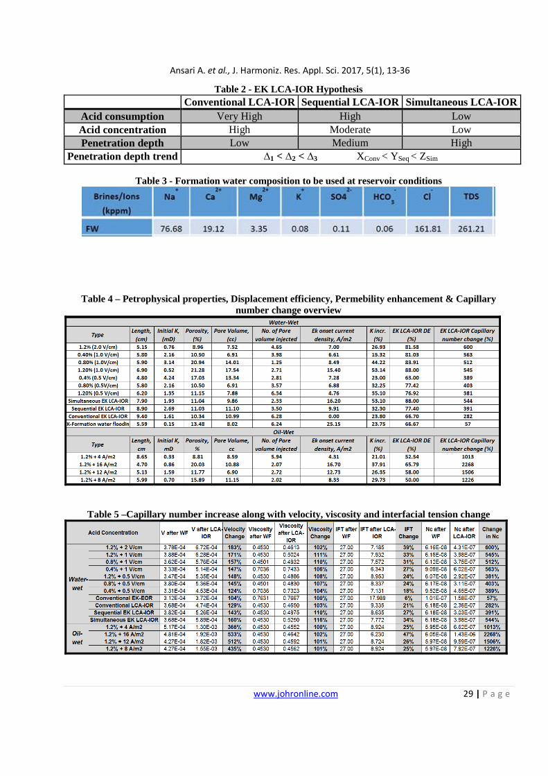
EK LCA-IOR Hypothesis: The EK Low-concentration acid IOR proposed hypothesis [Ansari et al., 2014] clearly indicates that Simultaneous EK LCA-IOR has the deepest depth of penetration as it guides the acid through a tortuous path preventing it from getting adsorbed too early on the rock surface, giving the maximum permeability enhancement and oil displacement efficiency with minimum amount and concentration of acid as seen in Table 2 and Fig. 3 below.
Experimental Methodology: Rock samples retrieved from producing Abu Dhabi reservoirs are taken from shallow (basal shale ~ 3500 ft, high porosity with low permeability), moderate (dolomitic limestone ~ 4500 ft), and deep reservoirs (~ 8500 feet) where the porosity in the reservoir ranges between 10 to 25%, and the permeability ranges from as low as 0.1 mD to as high as 16 Darcy. The experiments were conducted on 1.5” core samples in order to simulate and see the effect of EK LCA-IOR on displacement efficiency, permeability enhancement and capillary number at oil-wet and water-wet reservoir conditions.
Core Preparation: Initially carbonate core-plugs retrieved from Abu Dhabi producing fields, are cleaned with toluene and methanol solvents in the Soxilliate equipment. They are dried in an oven followed by the measurement of their rock properties such as permeability, porosity, pore volume and their saturation after placing them in a saturation cell with formation water (properties in Table – 3) for 24 hours at 2500 psi [Byrne and Patey, 2004, Sharma, 2000]. The core plugs were initially flooded with brine until the pressure stabilization stage where the initial liquid permeability (kabs) of the core was calculated using Darcy’s Law by measuring the differential pressure across the core using a pressure transducer [Robertson et al., 2003].
Then the cores were brought to oil saturation stage at an irreducible water saturation condition using medium crude oil (34.50 API, 3.5 cP) and the relative permeability of oil (kro) and initial oil-in-place (OOIP) were determined after bringing the core to initial reservoir conditions upon pressure stabilization. The last few experiments were conducted on oil-wet core plugs which were aged by placing them in an aging cell for about 4-6 weeks after which the cores were flooded with oil again in a series of experiments and the initial irreducible water saturation is measured which is verified to be significantly lower as compared to the water-wet core-plugs.
Water flooding: After saturating the core plugs with crude oil, water flooding was conducted with formation water at a rate of 0.25 ml/min (equivalent to average reservoir flow rate of 1ft/D for 1.5” cores) under reservoir conditions (temperature (80oC) and confined reservoir pressure (3000 psi) with the application of back pressure across the core). The cores are placed inside a rubber sleeve that fits inside a specially designed steel core holder with insulators at each end to provide insulation for electro kinetics [Fig.4]. The effluent fluid (oil, water or gas) was collected in a burette. Displacement efficiency is used to calculate the efficiency of the oil
Ansari A. et al., J. Harmoniz. Res. Appl. Sci. 2017, 5(1), 13-36
www.johronline.com 19 | P a g e
recovery process as the flow occurs only in 1-D. However, the recovery factor is used to define the oil recovery efficiency in the field when the 3-D radial flow occurs. The displacement efficiency (oil recovery equation – 1), permeability enhancement (found using
differential pressure from equation – 2) and capillary number enhancement (found using equation – 3) are the three immense properties that are measured until the pressure stabilizes to quantify the success of the process from equations below:
%100)(
)(∗=
OOIP
displaced
VplaceinOilInitialofVolume
VdisplacedoilofVolumeefficiencyntdisplacemeOil
…………………. (Equation 1)
initial
initialfinaltenhancemen K
KKK
−= .........………………….(Equation 2)
……… (Equation 3)
Where o ∆Nc = Change in Capillary Number, dimensionless o ∆v (in cms-1) = (v2 – v1) = (q2 – q1) / A o Fluid flow velocity difference calculated from difference of injection and effluent flow rate
divided by cross-sectional area o ∆µ (in cP (or) 0.01 g/cm-1s-1 ) = (µ2 – µ1)
Difference in viscosity of injection and effluent water using Cannon-Fenske Viscometer o ∆σ (in dynes/cm (or) g s-2) = (σ 2 – σ 1)
Difference in Interfacial tension of injection and effluent Oil-water using IFT Spinning Drop meter (Fig. 5)
The following mentions the equipment it contains and their functions: Hydrodynamic (Isco) flow pump – Helps to
inject, flow and move the fluid through the given core holder setup by providing hydrodynamic flow.
Core Viton Rubber/Steel core holder - Helps to provide a confinement pressure of 3000 psi and is kept horizontal to eliminate any gravitational effects as the reaction rate is highest when the acid is flowed in the direction of the gravitational force allowing the core-plug to be confined within a rubber sleeve and insulators are applied on either side to eliminate short circuit, through the core cross-sectional area [Mumallah, 1991]
Temperature coil and thermometers – Coil is used to apply high temperature for reservoir condition experiments and thermometers measure temperature at two different points at the inlet and outlet.
Pressure transducer – Helps to record the differential pressure across the core which is important to formulate into core permeability using Darcy’s Law.
Collector – Is usually a burette or a flask to collect the effluent
Electrokinetic DC voltage supply: It applies and measures the electro kinetic potential across the given carbonate core in order to measure the current density across the core and quantify other parameters from it.
Electrokinetic Low-concentration acid IOR Conventional LCA-IOR: After the waterflooding stage, conventional low-concentration acidizing was conducted by injecting acids of different concentrations (0.25% - 1.2%) in a series of experiments axially through the cores at a constant rate of 0.25 ml/min until ultimate water flood recovery was reached and the final permeability enhancement of the core and its ultimate oil recovery were measured.
Ansari A. et al., J. Harmoniz. Res. Appl. Sci. 2017, 5(1), 13-36
www.johronline.com 20 | P a g e
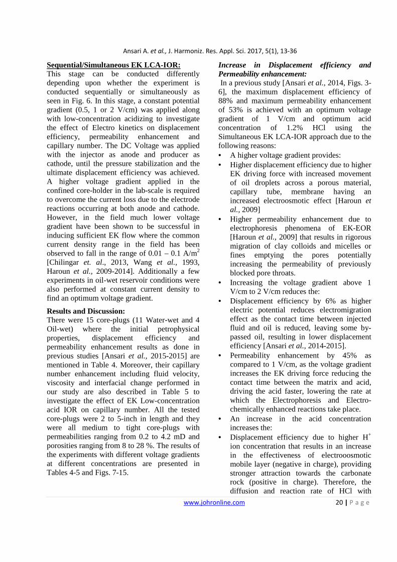
Sequential/Simultaneous EK LCA-IOR: This stage can be conducted differently depending upon whether the experiment is conducted sequentially or simultaneously as seen in Fig. 6. In this stage, a constant potential gradient (0.5, 1 or 2 V/cm) was applied along with low-concentration acidizing to investigate the effect of Electro kinetics on displacement efficiency, permeability enhancement and capillary number. The DC Voltage was applied with the injector as anode and producer as cathode, until the pressure stabilization and the ultimate displacement efficiency was achieved. A higher voltage gradient applied in the confined core-holder in the lab-scale is required to overcome the current loss due to the electrode reactions occurring at both anode and cathode. However, in the field much lower voltage gradient have been shown to be successful in inducing sufficient EK flow where the common current density range in the field has been observed to fall in the range of 0.01 – 0.1 A/m2 [Chilingar et. al., 2013, Wang et al., 1993, Haroun et al., 2009-2014]. Additionally a few experiments in oil-wet reservoir conditions were also performed at constant current density to find an optimum voltage gradient.
Results and Discussion: There were 15 core-plugs (11 Water-wet and 4 Oil-wet) where the initial petrophysical properties, displacement efficiency and permeability enhancement results as done in previous studies [Ansari et al., 2015-2015] are mentioned in Table 4. Moreover, their capillary number enhancement including fluid velocity, viscosity and interfacial change performed in our study are also described in Table 5 to investigate the effect of EK Low-concentration acid IOR on capillary number. All the tested core-plugs were 2 to 5-inch in length and they were all medium to tight core-plugs with permeabilities ranging from 0.2 to 4.2 mD and porosities ranging from 8 to 28 %. The results of the experiments with different voltage gradients at different concentrations are presented in Tables 4-5 and Figs. 7-15.
Increase in Displacement efficiency and Permeability enhancement: In a previous study [Ansari et al., 2014, Figs. 3-6], the maximum displacement efficiency of 88% and maximum permeability enhancement of 53% is achieved with an optimum voltage gradient of 1 V/cm and optimum acid concentration of 1.2% HCl using the Simultaneous EK LCA-IOR approach due to the following reasons: • A higher voltage gradient provides: • Higher displacement efficiency due to higher
EK driving force with increased movement of oil droplets across a porous material, capillary tube, membrane having an increased electroosmotic effect [Haroun et al., 2009]
• Higher permeability enhancement due to electrophoresis phenomena of EK-EOR [Haroun et al., 2009] that results in rigorous migration of clay colloids and micelles or fines emptying the pores potentially increasing the permeability of previously blocked pore throats.
• Increasing the voltage gradient above 1 V/cm to 2 V/cm reduces the:
• Displacement efficiency by 6% as higher electric potential reduces electromigration effect as the contact time between injected fluid and oil is reduced, leaving some by-passed oil, resulting in lower displacement efficiency [Ansari et al., 2014-2015].
• Permeability enhancement by 45% as compared to 1 V/cm, as the voltage gradient increases the EK driving force reducing the contact time between the matrix and acid, driving the acid faster, lowering the rate at which the Electrophoresis and Electro-chemically enhanced reactions take place.
• An increase in the acid concentration increases the:
• Displacement efficiency due to higher H+ ion concentration that results in an increase in the effectiveness of electrooosmotic mobile layer (negative in charge), providing stronger attraction towards the carbonate rock (positive in charge). Therefore, the diffusion and reaction rate of HCl with
Ansari A. et al., J. Harmoniz. Res. Appl. Sci. 2017, 5(1), 13-36
www.johronline.com 21 | P a g e
carbonates enhances the viscous forces at the interface of mobile layer to contact and displace more of the by-passed oil not contacted originally [Ansari et al., 2014-2015].
• Effective reservoir permeability due to higher H+ ion concentration that results in an increase in the rate of reaction between HCl and carbonates, elevated at high formation temperatures.
• Simultaneous EK LCA-IOR yields the maximum displacement efficiency of 88% as compared to sequential EK LCA-IOR (78%) and conventional LCA-IOR (66%). This is because simultaneous EK LCA-IOR enhances the depth of penetration with a precise targeted transport of acid through a tortuous path within the micro pores creates new channels and microfractures as acid migrates towards the cathode in the presence of EK leading to increased oil sweep efficiency with negligible acid adsorption at the rock surface. In addition, all the EK drive mechanisms (Electrosomostic force, hydrodynamic force, microemulsions force) work in conjunction simultaneously in an integrated manner on one big volume of by-passed oil to produce one cumulative net driving force [Ansari et al., 2014-2015].
• On average, oil-wet cores have 34% lower permeability enhancement and displacement efficiency as compared to water-wet cores but 55% higher incremental permeability enhancement and displacement efficiency (Fig.7) as some of the by-passed oil might be clogging the micro-pores and pore throats not allowing the acid to enter micro and nano pores leading to a partial sweep reducing the surface contact area of acid with matrix and oil resulting in lower electrochemically enhanced reactions and reduced electromigration taking place.
Fluid velocity increase Water-wet results (Fig. 8a) indicate that the acid velocity increases by 124-183% as the acid concentration increases due to the enhanced reaction rate with higher H+ concentration leading to acid penetrating deeper and diffusing
more rapidly into the formation. However, the fluid velocity starts to decrease at higher acid concentrations (above 1.2% HCl) due to larger production of CO2 and CaCl2 that impedes the fluid flow velocity. In addition to this, the velocity increases with increasing voltage gradient from 0.5 V/cm to 2 V/cm (Fig. 8b) due to an increase in the electroosmotic force [Chilingar et al., 2014]
Oil-wet experiments are seen to have 360-530% fluid velocity increase which is 300% higher as compared to water-wet results (Fig. 8b). In addition to this, the increase in the current density shows a significantly higher fluid (acid) velocity in Oil-wet core-plugs (66%) as compared to Water-wet core-plugs (20%). The main reason is due to the electro kinetics working and dragging larger localized accumulated oil drops inside pore throats resulting in providing stronger electroosmotic double layer dragging more oil and acid along an increased rock surface area causing higher permeability enhancement with higher mobilization of ions along with free water leading to high current density and minimum voltage consumption.
Interfacial tension decrease: The Interfacial tension between oil and water decreases as the fluid (acid) reacts and travels from the anode to the cathode. Therefore, the change in interfacial tension for influent and effluent were calculated from Spinning Drop meter (Fig. 5) and plotted for experiments carried on oil-wet and water-wet core-plugs:
Water-wet results (Fig. 9a) indicate that for all three voltage gradients, change in interfacial tension decreases with increasing acid concentration by approximately 55-65% with the Conventional LCA-IOR and 18-40% with EK-LCA IOR. The main reason for the decrease in both the stages is due to the insitu formation of microemulsions (surfactant) as a result of the electrolysis reactions between the carboxylic acids present in the oil and the electrolysis products of brine & HCl, resulting in the diffusion or migration of the products up to the interface as mentioned theoretically in a
Ansari A. et al., J. Harmoniz. Res. Appl. Sci. 2017, 5(1), 13-36
www.johronline.com 22 | P a g e
previous study [Fleureau and Dupeyrat, 1987]. Another study [Craft et al., 1990] also indicates that the generation of insitu microemulsions (surfactant) takes place when an alkaline solution is mixed with certain crude oils due to the chemical reactions between the alkaline solution and the oil. The insitu generated microemulsions reduces the interfacial tension between the oil phase and water phase. Therefore, the capacity of the aqueous phase to displace the trapped oil phase from the pores of rock matrix increases and the reduction of interfacial tension causes the microscopic displacement efficiency to increase, thereby increasing oil recovery and increase in capillary number. Moreover, this decrease in interfacial tension increases with increasing acid concentration (Fig. 9b) due to higher H+ ion concentration and acid number leading to an increase in the generation of microemulsions. In addition to this, it can also be observed that as voltage gradient increases from 0.5 to 2 V/cm, the amount of decrease in interfacial tension also increases. Therefore, 2 V/cm has the highest decrease in interfacial tension as the higher voltage gradient increase provides a higher electrolysis reaction rate between the carboxylic acids present in the oil and the electrolysis products of brine and HCl, generating more microemulsions as a result of increase in electro kinetic force.
Oil-wet experiments are seen to have 30% higher decrease in interfacial tension as compared to water-wet core-plugs as seen in Fig. 9b. This is because the electroosmotic double layer in oil-wet rocks is stronger with more trapped oil leading to increased acid-oil reactions due to heavier oil products resulting in a larger amount of microemulsions being generated. In addition to this, the increase in the current density and voltage gradient shows a significant decrease in interfacial tension which is 10-15% higher in oil-wet core-plugs. This is due to the larger electro kinetic force applied leading to a higher rate of the electrolysis reactions which causes a change in the rock
surface resulting in decreasing the energy between oil and water phases.
Capillary number (Nc) increase The change in capillary number was calculated based on the change in velocity of acid, change in viscosity of acid and change in interfacial tension between oil and fluid (acid)
Water-wet results in Fig. 10 indicate a 200-600% increase in the capillary number which is mainly due to the fluid velocity increase by 124-183% (Fig.8a) and decrease in Interfacial tension by approximately 55-65% (Fig.9a). It can be seen from Fig. 11 that the interfacial tension decreases significantly after the application of EK LCA-IOR (Fig.11a) and in the Simultaneous EK LCA-IOR process (Fig.11b). This is because the increase in capillary number is mainly due to the use of higher voltage gradient and current density, as there is an increase in electrolysis reaction rate between carboxylic acid in oil and the electrolysis products of brine and HCl, producing increased amount of microemulsions (surfactant), decreasing the interfacial tension and increasing the capillary number.
Oil-wet results in Fig. 10b indicate a 1000-2200% increase in capillary number which is 5 times more than water-wet results, due to the stronger electroosmotic double layer, contacting increased amount of oil leading to further decrease in interfacial tension. This is correlating with the injected pore volume results where oil-wet core-plugs need 5 times more pore volume to be injected as compared to water-wet core-plugs [Ansari et al., 2015]. Moreover, it was also observed that the increase in current density, increases the capillary number, which reaches an exponential plateau at a current density of around 16 A/m2 beyond which the increase in capillary number stabilizes at approximately 2200% and does not increase further beyond that point. Sensitivity analysis (Fig. 12) indicates that IFT change is the major component affecting the change in capillary number and the velocity and viscosity change also have influence but at a minimum level. Moreover, it can also be seen
Ansari A. et al., J. Harmoniz. Res. Appl. Sci. 2017, 5(1), 13-36
www.johronline.com 23 | P a g e
from Fig. 12a that velocity and viscosity are affecting in a positive way whereas interfacial tension is affecting negatively. Comparison of Capillary number change between conventional, sequential and simultaneous LCA-IOR (Fig. 13) clearly indicates that simultaneous EK LCA-IOR yields the maximum change in capillary number of 540% which is 39% more than that of sequential EK LCA-IOR (390%) and 90% more than that of conventional LCA-IOR (282%). The main reason is that simultaneous EK-LCA IOR results in taking the advantage of all the EK drive mechanisms working in conjunction with acidizing reactions in an integrated manner, resulting in higher fluid velocity with a larger decrease in interfacial tension. However, Conventional Electro kinetics with formation waterflooding results in the least capillary number change of around 12% due to only 5% change in interfacial tension (Fig.9). The success and proof of EK-LCA IOR process is demonstrated in Figs. 14 a and b where the displacement efficiency and permeability enhancement as a function of increase in capillary number have a strong positive linear correlation (a large value of co-efficient of determination), where increase in displacement efficiency (Fig. 14a) and permeability enhancement (Fig. 14b) increases the capillary number as a result of EK LCA-IOR method.
Moreover, to yield a 35% increase in displacement efficiency or permeability enhancement on average, a 400% increase in capillary number is obtained in water-wet core-plugs whereas a 1200% increase in capillary number is obtained in oil-wet core-plugs. Therefore, to yield similar incremental permeability enhancement or displacement efficiency the change in capillary number is three times more in oil-wet core-plugs as compared to water-wet core-plugs.
Enhanced Depth of Penetration as a proof of change in capillary number: Wang et al. (1993) conducted linear core flood experiments after matrix acidizing carbonates with the use of Computed-tomography (CT) scan images of acidized cores that indicated changes in wormhole shape along the acid efficiency curve. Single Energy CT Scan results on core samples before and after the experiments were analyzed and used to prove the hypothesis proposed for the depth of penetration for conventional, sequential and simultaneous Low-concentration acid IOR flooding in Fig. 3. The porosity based colorful images indicate blue as the minimum porosity or tight cores and green as the maximum porosity or permeable cores. It can be seen from Fig. 15 that the depth of penetration are approximated as follows along with justification:
• Conventional LCA-IOR mechanisms take place without the electro kinetics support as the acid takes the least tortuous path and gets adsorbed at the rock surface.
• Sequential LCA-IOR guided by conventional LCA-IOR mechanisms initially causes moderate adsorption however, after the application of EK LCA-IOR, the acid takes the tortuous path and the rate of adsorption is reduced allowing the acid to travel deep into the formation (twice of Conventional LCA-IOR) enhancing displacement efficiency and reducing injected pore volumes of acid (Figs. 3-4 from Ansari et al., 2014)
• Simultaneous EK LCA-IOR allows all Electrokinetic and LCA-IOR mechanisms to act on one big volume of oil in an organized congregated manner taking the acid through the most tortuous path penetrating deepest into the formation (2.5 times of Conventional LCA-IOR) enhancing displacement efficiency and reducing injected pore volumes significantly.
EK Low-concentration acid IOR Economics: An innovative approach of analyzing and comparing the economic and environmental feasibility of EK LCA-IOR process with other
Ansari A. et al., J. Harmoniz. Res. Appl. Sci. 2017, 5(1), 13-36
www.johronline.com 24 | P a g e
EK-EOR processes by calculating cost ($) to produce 1 barrel of oil. The cost ($/bbls) of producing 1 barrel of oil for each scenario was found based on CAPEX, OPEX and the amount of electricity consumed during the Electro kinetics process for each scenario, where the current density and voltage gradient were used based on the resistivity reading (0.15 Ωm) to quantify the power consumption (Table – 7). It can be seen from the table-7 and Fig.9, that EK LCA-IOR process has the minimum cost of producing 1 barrel of oil of approximately 11 $/bbl for a given field area of 20000 square metre and spatial distance between electrodes of approximately 1 kilometer, although it has higher current density and power consumption than EK-Nano EOR and EK-Surfactant EOR. However, due to lower acid consumption and lower unit acid cost, EK LCA-IOR has the lowest electricity cost for producing 1 barrel of oil with the trend as follows:
Conclusion: A novel green EK LCA-IOR process was investigated for enhancing displacement efficiency, capillary number and stimulation effect. This potentially increases economic and environmental feasibility. Based on the findings, a comparison was conducted
and following conclusions were drawn for both Mixed Oil-wet and Water-wet core-plugs at Reservoir conditions: • EK Low-concentration acid IOR: • Enhances formation stimulation results by
29% due to electrophoresis phenomena Kenhconv = 23.8% < KenhSeq = 32.3% <
KenhSim = 53.1% Improves displacement efficiency by 15%
due to electroosmosis phenomena DEconv = 61.9% < DESeq = 77.4%< DESim =
2.8PV Enhances electrical conductivity in reservoir
and thus, increases connectivity of pores through the smallest conduits thereby, enhancing contact with previously by-passed oil.
Power consumption was increased by 20% Enhances particle mobility of acid and H+
ions with an improved depth of penetration into the carbonate reservoir core-plugs or other oil-bearing formations as confirmed by SECT Scan results:
DepthConv LCA-IOR (35%) < DepthSeq EK-LCA IOR (70%) < DepthSim EK-LCA IOR (82%) Has a minimum cost of producing oil of $
11/bbl Induces and/or modifies the surface of the
carbonate reservoir rock or other oil-bearing formations, and hence, alters the wettability to a more desirable state for oil recovery.
• Interfacial tension decreases with increasing the acid concentration due to improved electrolysis reactions between the carboxylic acids present in oil, where the electrolysis products of brine and HCl increases as a result of increasing ion concentration.
• EK LCA-IOR process results in oil-wet core-plugs to have an additional 40% decrease in interfacial tension coupled with a 500% increase in capillary number as compared to water-wet core-plugs.
• Water-wet core-plugs indicate a 200-600% increase in the capillary number
• Oil-wet core-plugs indicate a 1000-2200% increase in capillary number
• The change in capillary number trend was observed as follows as a function of EK LCA-IOR process, voltage gradient and current density, respectively:
Current research phase undergoing at the PI-EKRC is targeted towards using EK LCA-IOR
to optimize injection schedule, injection mechanism and rate and measure zeta potential
Ansari A. et al., J. Harmoniz. Res. Appl. Sci. 2017, 5(1), 13-36
www.johronline.com 25 | P a g e
of the core in order to map the zeta potential to contact angle at varying temperature, mineralogical content and fluid composition. This will verify our proposed theory of increase in capillary number and help explain why both EK-EOR and EK LCA-IOR have an effect on reducing oil saturation and in turn, augment the wettability alteration targeting the previously by-passed oil in Abu Dhabi Carbonates.
Acknowledgement: The authors are thankful to the Petroleum Engineering Department, The Petroleum Institute, Abu Dhabi and ADNOC, for providing the Electrokinetic research center (PI-EKRC) and support needed to conduct this research.
References • Acar, Y. B., Alshawabkeh, A. N., Parker,
R.A., (1997), Theoretical and Experimental Modeling of Multi-Species Transport in Soils under Electric Fields, National Risk Management Research Laboratory, Office of Research and Development, U.S. Environmental Protection Agency Cincinnati, OH 45268, September 1997, EPA/600/R-97/054
• ACAR, Y.B., LI, H., and GALE, R.J. (1992). Phenol removal from kaolinite by electrokinetics. ASCE J. Geotech. Eng. 118(11), 1837–1852.
• ACAR, Y.B., HAMED, J.T., ALSHAWABKEH, A., and GALE, R.J. (1994). Cd(II) removal from saturated kaolinite by application of electrical current. Géotechnique 44(3), 239–254.
• ACAR, Y.B., and ALSHAWABKEH, A. (1993). Principles of electrokinetic remediation. Environ. Sci. Technol. 27(13), 2638–2647.
• Alkafeef, S.F. and Alforgi, M.Z. Review of and Outlook for Enhanced Oil Recovery Techniques in Kuwait Oil Reservoirs, IPTC 11234, December 2007
• AlOtaibi M. B., Nasralla R. A., Nasr-El-Din, H. A., Wettability Studies Using Low-Salinity Water in Sandstone Reservoirs, Society of Petroleum Engineers, SPE149942,
http://dx.doi.org/10.2118/149942-PA, Published in the SPE Reservoir Evaluation & Engineering, Volume 14, Issue 06, December 2011.
• Ansari, A., Haroun, M. R., Sayed, N. A.,Kindy, N., Ali, B., Shrestha, R. A., Sarma, H., 2012, A New Approach Optimizing Mature Waterfloods with Electrokinetics- Assisted Surfactant Flooding in Abu Dhabi Carbonate Reservoirs, SPE 163379, Published in the SPE Kuwait International Petroleum Conference Dhabi International Petroleum Exhibition and Conference, KIPCE 2012, (09th – 13th December 2012)
• Ansari A., Haroun M., Rehman, M., Chilingar, G.V., Increasing Depth of Penetration by Electrokinetic Driven Low-Concentration Acid IOR in Abu Dhabi Tight Carbonate Reservoirs, Society of Petroleum Engineers, SPE 171936, Published in the SPE Abu Dhabi International Petroleum Exhibition and Conference, ADIPEC 2014, (10th – 13th November 2014).
• Ansari, A, Investigation of Electrokinetic Low-Concentration Acid IOR (EK LCA-IOR) for Abu Dhabi Carbonate Reservoirs. MSc. Dissertation in Petroleum Engineering, The Petroleum Institute, Abu Dhabi, (2014), 247 pp.
• Ansari, A., Haroun, M., Rehman, M.R., Chilingar, G.V., (2014), Electrokinetic Driven Low-Concentration Acid Improved Oil Recovery in Abu Dhabi Tight Carbonate Reservoirs, Electrochimica Acta Special Issue (Impact Factor: 4.5). 05/2015, Elseviers 2015, presented at Electrokinetic Remediation Conference, EREM 2014, 07th – 10th September, 2014.
• Ansari, A., Haroun M., Rehman, M., Chilingar, G.V., (2016), A Novel Cost-Effective Approach for Enhancing Capillary number while Stimulating Abu Dhabi Tight Carbonate Reservoirs, Society of Petroleum Engineers, SPE 182046, Published in the SPE Russian Petroleum Technology Conference, RPTC 2015, Moscow, Russia (24th–26th October 2016)
Ansari A. et al., J. Harmoniz. Res. Appl. Sci. 2017, 5(1), 13-36
www.johronline.com 26 | P a g e
• Ansari A., Haroun M., Rehman, M., Sarma, H., Chilingar, G.V., (2015), Enhancing depth of penetration to improve capillary number by Application of EK Low-concentration Acid IOR in Abu Dhabi Carbonate Reservoirs, Society of Petroleum Engineers, SPE 174320, Published in the SPE EUROPEC 2015 Madrid, Spain 2015, (02nd–03rd June 2015).
• Ansari, A., Haroun M., Rehman, M., Chilingar, G.V., Sarma, H., (2015), A Novel IOR approach for increasing capillary number by enhancing depth of penetration in Abu Dhabi Carbonate reservoirs, Society of Petroleum Engineers, SPE 177780, Published in the SPE Abu Dhabi International Petroleum Exhibition and Conference, ADIPEC 2015, (09th–13th November 2015).
• Ansari, A., Haroun M., Rehman, M., Chilingar, G.V., (2015), Assessing the environomic feasibility of Electrokinetic Low-Concentration Acid IOR in Abu Dhabi Carbonate Reservoirs, Society of Petroleum Engineers, SPE 178124, Published in the SPE Oil and Gas India Conference and Exhibition, OGIC 2015, Mumbai, India (24th–26th November 2015).
• Anderson, W.G.; Wettability Literature Survey - Part 5: The Effect of Wettability on Relative Permeability, JPT (Nov. 1987), 1453-1467.
• Behrens, C. E., Glover, C., 2012, U.S. Energy: Overview and Key Statistics, CRS Report for Congress
• Bentsen. R.G., and Manai A.A. (1993), On the use of conventional concurrent and counter current effective permeabilities to estimate the four generalized permeability coefficients which arise in coupled two phase flow. Journal of transport in porous media, Vol. 11, pages 243-262, 1993
• Byrne, M. and Patey, I., Core Sample Preparation – An Insight in to New Procedures, SCA2004-50
• Churcher, P.R., French, J.E., Shaw, and L.L., Schramm, 1991, Rock Properties of Berea
Sandstone, Baker Dolomite, and Indiana Limestone, SPE 21044, pg 431-445
• Chilingar, G.V., 1964. Relationship Between Porosity, Permeability, and Grain Size distribution of Sands and Sandstones, Developments in Sediminetology, Volume 1, pp. 71-75.
• Chilingar G., Shin S., M. Haroun, A. Albannay, K. Wittle, N. Meshkati and S. Pamukcu, Improving Acidizing Opeations, Journal of Environmental Protection, Vol. 4 No. 4A, 2013, pp. 1-3. DOI:10.7569/JSEE.2013.629514
• Chilingar G.V., Haroun M., “Electrokinetics for Petroleum Environmental Engineers Volume I,” Wiley Publishing Press, 2014, ISBN: 978-1-118-84269-0
• Craft, B.C., Hawkins, M., Terry R.E., (1990) Applied Petroleum Reservoir Engineering, Second Edition, Prentice Hall PTR, Eaglewood Cliffs NJ 07632, (1990).
• EYKHOLT, G.R. (1992). Driving and complicating features of electrokinetic treatment of soils. PhD dissertation, Dept. of Civ. Eng., Univ. of Texas at Austin, TX.
• Fleureau, J, M., Dupeyrat, M., 1988, Influence of an Electric field on the Interfacial Parameters of a Water/Oil/Rock System: Application to Oil Enhanced Recovery, Journal of Colloid and Interface Science, Vol. 123, No.1, May 1988.
• Haroun, M. R., 2009, Ph.D. Dissertation in Petroleum Engineering Feasibility of EEOR in Carbonate Rock Formations, pp. 365
• Haroun, M. R., Chilingar, G.V., Pamukcu, S., Wittle, J. K., Belhaj, H. A., Al Bloushi, M. N., Optimizing Electroosmotic Flow Potential for Electrically Enhanced Oil Recovery (EK-EOR) in Carbonate Rock Formations of Abu Dhabi Based on Rock Properties and Composition, Society of Petroleum Engineers, IPTC 13812, (2009).
• Haroun, M., Alhassan, S., Ansari, A., Al Kindy, N., Abou Sayed, N., Abdul Kareem, B., and Sarma, H., 2012. Smart Nano-EOR process for Abu Dhabi carbonate reservoirs. SPE 162386 Published in the SPE Abu Dhabi International Petroleum Exhibition
Ansari A. et al., J. Harmoniz. Res. Appl. Sci. 2017, 5(1), 13-36
www.johronline.com 27 | P a g e
and Conference, ADIPEC 2012, (09th–12th November 2012).
• Haroun M., Wittle J. K., Chilingar G. V., Patent Publication No. WO/2012/074510 Title of the invention: METHOD FOR ENHANCED OIL RECOVERY FROM CARBONATE RESERVOIRS. Applicants: ELECTRO-PETROLEUM, INC. (US), GENEVA, June 7th, 2012.
• Haroun M., Ansari A., Al Kindy N., Abou Sayed N., Ali B., Shrestha R., Sarma H., Application of Electrokinetics to Achieve Smart EOR in Abu Dhabi Oil-Wet Carbonate Reservoirs Abstract at Electrokinetic Remediation Conference, EREM 2013, (23rd-26th June, 2013).
• Haroun M., (2013), Emerging EOR Technologies. OPEC R&D Forum, OPEC Secretariat, Vienna, Austria, May 7-8, 2013
• Hirasaki, G.J., 1988. Wettability: fundamental and surface forces. SPE/DOE paper 17367
• Kia, S. F., Fogler, H. S., Reed, M. G., Vaidya, R.N., 1987, Effect of Salt composition on clay release in Berea sandstone, SPE 16254, SPE Production Engineering, November 1987, Page 277.
• Leone, J. A., Scott, E. M.: SPE Reservoir Eng., November 1988
• Mumallah, N.A. 1991. Factors influencing the Reaction Rate of Hydrochloric acid and Carbonate Rock. Paper SPE 21036 presented at the SPE International Symposium on Oilfield Chemistry, Anaheim, California, 20-22 February.
• Oil and Gas Journal EOR Surveys, EOR surveys 1970-2030, US-Oil-Production-1965-through-2013-Fracking.png?00cfb7, Available [Online]: www.energytrendsinsider.com909 × 660Search by image
• PAMUKCU, S., and WITTLE, J.K. (1992). Electrokinetic removal of selected heavy metals from soil. AIChE Environ.Prog. 11(3), 241–250.
• Portier, S., André, L., Vuataz, F.D., 2007, Review on chemical stimulation techniques
in oil industry and applications to geothermal systems, CREGE – Centre for Geothermal Research, Neuchâtel, Switzerland, May 2007
• Robertson, E. P., Thomas, C. P., Zhang, Y., and Morrow, N. R., Improved Waterflooding through Injection-Brine Modification, INEEL/EXT-02-0159, 2003.
• Sarma, H.K., Maini, B.B., and Allen, G., Effect of Viscous Instability on Unsteady-State Relative Permeability. Revue de L'Institut Francais du Petrole (1992), 47, 753-770.
• Schramm, L. L., Mannhardt K., Novosad, J. J.: Electrokinetic properties of reservoir rock particles, Journal of Colloids and surfaces, Elsevier Science Publishers B.V., Amsterdam, 55, 1991, pp. 309-331. DOI: 0166-6622/91/$03.50.
• Seethepalli, A., Adibhatla, B., and Mohanty, k.: Wettability Alteration during Surfactant Flood in Carbonate Reservoirs, Paper presented in SPE/DOE Symposium on Improved Oil Recovery (Apr 17 – 21, 2004) Tulsa USA
• Sharma, M. M.: Effect of Brine Salinity and Crude-oil Properties on Oil Recovery and Residual Saturation, SPEJ 5(3) pp.293-300, 2000
• Shedid, S. A.: An experimental approach of matrix acidizing of permeability-damaged carbonate reservoirs, SPE EUROPEC presented in London, United Kingdom, 11-14 June 2007
• Taber, J.J., Martin, F.D., Seright, R.S., EOR Screening criteria Revisited-Part1: Screening criteria and introduction to enhanced recovery field projects, SPE Reservoir Engineering (August 1997). SPE 35385 presented at the SPE/DOE Improved Oil recovery Symposium, Tulsa, Okhlahoma, 21-24 April, 1996.
• Tewari, D.C., 2009, Enhanced Oil Recovery techniques, Institute of Reservoir Studies Oil and Natural Gas Corporation Limited, Ahmedabad.
• U.S. Energy Information Administration (EIA), Brent month future prices, 2015,
Ansari A. et al., J. Harmoniz. Res. Appl. Sci. 2017, 5(1), 13-36
www.johronline.com 28 | P a g e
Available [Online]: www.eia.gov845 × 503Search by image
• Wang, Y., Hill, A.D., Schechter, R.S., 1993, The Optimum Injection Rate for Matrix Acidizing of Carbonate Formations, SPE 26578, pg 657-687
• Wittle, J. K., Hill, D.G., Chilingar, G.V., 2008, Direct Current Electrical Enhanced Oil Recovery in Heavy-Oil Reservoirs to Improve Recovery, Reduce Water Cut, and Reduce H2S Production while Increasing API Gravity, Society of Petroleum Engineers, SPE 114012.
• WPC, SPE/WPC/AAPG/SPEE Petroleum Resources Management System (PRMS), Prepared by the SPE Oil & Gas Reserves Committee (OGRC), 2007.
• World Petroleum Council (WPC), [Cited 2014]. [Online Document], Available HTTP: http://www.world-petroleum.org/
• Yousef, A.A., Al-Saleh, S., and Al-Jawfi, M. 2012a. Improved/Enhanced Oil Recovery From Carbonate Reservoirs by Tuning Injection Water Salinity and Ionic Content. Presented at the SPE Improved Oil Recovery Symposium, Tulsa, Oklahoma, 14–18 April. SPE-154076-MS. http://dx.doi.org/10.2118/154076-MS.
• Yousef, A.A., Liu, J. S., Blanchard, G.W. et al. 2012b. SmartWater Flooding: Industry’s First Field Test in Carbonate Reservoirs. Presented at the SPE Annual Technical Conference and Exhibition, San Antonio, Texas, 8–10 October. SPE-159526-MS. http://dx.doi.org/10.2118/159526-MS.
Table 1 – Limitations of other EOR forms
Ansari A. et al., J. Harmoniz. Res. Appl. Sci. 2017, 5(1), 13-36
www.johronline.com 29 | P a g e
Table 2 - EK LCA-IOR Hypothesis
Table 3 - Formation water composition to be used at reservoir conditions
Table 5 –Capillary number increase along with velocity, viscosity and interfacial tension change
Conventional LCA-IOR Sequential LCA-IOR Simultaneous LCA-IOR Acid consumption Very High High Low Acid concentration High Moderate Low Penetration depth Low Medium High
Ansari A. et al., J. Harmoniz. Res. Appl. Sci. 2017, 5(1), 13-36
www.johronline.com 30 | P a g e
Table 6 – Calculations for Electricity cost for oil production ($/bbls) for different scenarios
Fig. 1 - Schematic diagram showing development of wettability [Seethipalli et al., 2004].
Fig. 2 – Mechanism to enhance oil recovery during EK LCA-IOR injection [Haroun et al., 2014, Ansari et al., 2014]
Ansari A. et al., J. Harmoniz. Res. Appl. Sci. 2017, 5(1), 13-36
www.johronline.com 31 | P a g e
Fig. 3 – Schematics for EK LCA-IOR Hypothesis
Fig. 4 –EK LCA-IOR Lab apparatus in PI-EKRC for cor e flooding at reservoir lab conditions
Fig 5 – Spinning Drop (IFT) measurement
Ansari A. et al., J. Harmoniz. Res. Appl. Sci. 2017, 5(1), 13-36
www.johronline.com 32 | P a g e
Fig. 6 – EK Low-concentration acid IOR Approach [Ansari et al., 2014]
Fig. 7 – (a) Oil Displacement efficiency and (b) Permeability enhancement as a function of injected
pore volumes to compare between oil-wet and water-wet cores
Ansari A. et al., J. Harmoniz. Res. Appl. Sci. 2017, 5(1), 13-36
www.johronline.com 33 | P a g e
Fig. 8 – Comparison of fluid velocities as a function of (a) acid concentration and (b) voltage gradient
Fig. 9 – Comparison of interfacial tension change as a function of (a) acid concentration and (b) voltage gradient
Fig. 10 – Change in capillary number as a function of (a) acid concentration and (b) current density
Ansari A. et al., J. Harmoniz. Res. Appl. Sci. 2017, 5(1), 13-36
www.johronline.com 34 | P a g e
Fig. 11 – Comparison of change in Capillary number between different (a) phases (b) EK LCA-IOR
approaches
Fig. 12 – Sensitivity Analysis for Change in capillary number mostly affected by Interfacial tension change
Fig. 13 – Summary of change in comparison of change in Capillary number
Ansari A. et al., J. Harmoniz. Res. Appl. Sci. 2017, 5(1), 13-36
www.johronline.com 35 | P a g e
Fig. 14 – (a) Displacement efficiency and (b) Permeability enhancement as a function of capillary
number change
Fig. 15 – Comparison of depth of penetration through SECT scan imaging before and after Conventional (top), Sequential (middle) and Simultaneous (bottom) LCA-IOR flooding
Ansari A. et al., J. Harmoniz. Res. Appl. Sci. 2017, 5(1), 13-36
www.johronline.com 36 | P a g e
Fig. 16 - Comparison of cost for producing oil ($/bbls) based on UAE cost of electricity