+ All Categories
Home > Documents > 3246 T80463EN

3246 T80463EN

Date post: 16-Feb-2018
Category:
Upload: mlachenal5237
View: 226 times
Download: 0 times
Share this document with a friend
10
 Application Mix ing or flo w-d ive rti ng val ve for cryo gen ic app lications Nominal size NPS ½ to 6 Pressure rating ANSI Class 150 and 300 Temperatures 200 to 220 °C · 328 to 428 °F Type 3246 Three-way Valve with: Type 3271 Pneumatic Actuat or (Type 3 246-1Control Valve) or Type 32 77 Pneuma ti c Ac tuator (T ype 32 46 -7 Control Va lv e) for integral attachment of a positioner  Valve body made of: • Stain less carbon steel Low-noise valve plug with: Meta l se al ing or  • Lap ped -in me tal The modular design of the control valves allows them to be equipped with various accessories: Pos itioners, solenoid val ves and oth er access ori es according to IE C 60534-6 and NAMUR recommen da ti on. See Informat ion Sheet T 8350 EN for details.  Version Standard ver sion  with single PTFE packing for temperatures ranging from 200 to 220 °C (328 to 428 °F) with long insu la tin g section an d circ ul ation in hib itor , nom in al si zes NPS½to6, ANSI Cl ass 150 an d 300, wi th fl an ge swi th Rais ed Face Ty pe 32 46 -1 · With Type 3271Actuator with 120 to 700 cm² effective diaphragm area (refer to T 8310-1 EN) Ty pe 32 46 -7 · With Type 3277Actuator with 120 to 700 cm² effective diaphragm area (refer to T 831 0-1 EN) Other versions Typ e 324 6-1 /-7 Glo be Valve · wit h lon g insulatin g sec tion and circulation inhibitor, NPS ½ to 10,up to ANSI Class 300 · Refer to Data Shee t T 8 046-1 EN Typ e 324 6-1 /-7 Glo be Valve · wit h lon g insulatin g sec tion an d ci rc ul at ion inhi bi tor, NPS ½ to 6,ANSI Cl as s 600 · Re- fer to Dat a Sheet T 8046-2 E N  Associated Information Sheets T 8000-1/-2/-3 EN Data Sheet for pneumatic actuators T 8310-1 EN Mounting and Operating Instructions EB 8026 EN Edition September 2006 Dat a & Servicin g Sh eet T 8046-3 EN Fig. 1 · Type 32 46-7 wit h circu latio n inhib itor, f lang es, long insulating section and cover plate with collar Fig. 2 · Type 3246 w ith c ircul ation inhibi tor Pneumatic Control Valve Type 3246-1 and Type 3246-7 Three-way Valve Type 3246  ANSI Class 150 and 300 with long insulating section a nd circulation inhibitor  ANSI version
Transcript

7/23/2019 3246 T80463EN

http://slidepdf.com/reader/full/3246-t80463en 1/10

 Application

Mixing or flow-diverting valve for cryogenic applicationsNominal size NPS ½ to 6Pressure rating ANSI Class 150 and 300Temperatures –200 to 220 °C · –328 to 428 °F

Type 3246 Three-way Valve with:

Type 3271 Pneumatic Actuator (Type 3246-1Control Valve)or 

• Type 3277 Pneumatic Actuator (Type 3246-7 Control Valve)for integral attachment of a positioner 

 Valve body made of:• Stainless carbon steel

Low-noise valve plug with:• Metal sealing or 

• Lapped-in metalThe modular design of the control valves allows them to beequipped with various accessories:Positioners, solenoid valves and other accessories according toIEC 60534-6 and NAMUR recommendation. See InformationSheet T 8350 EN for details.

 VersionStandard version  with single PTFE packing for temperaturesranging from –200 to 220 °C (–328 to 428 °F) with longinsulating section and circulation inhibitor, nominal sizesNPS ½ to 6, ANSI Class 150 and 300, with flanges with RaisedFace

– Type 3246-1 · With Type 3271 Actuator with 120 to700 cm² effective diaphragm area (refer to T 8310-1 EN)

– Type 3246-7 · With Type 3277 Actuator with 120 to700 cm² effective diaphragm area (refer to T 8310-1 EN)

Other versions

– Type 3246-1/-7 Globe Valve · with long insulating sectionand circulation inhibitor, NPS ½ to 10, up to ANSIClass 300 · Refer to Data Sheet T 8046-1 EN

– Type 3246-1/-7 Globe Valve · with long insulating sectionand circulation inhibitor, NPS ½ to 6, ANSI Class 600 · Re-fer to Data Sheet T 8046-2 EN

 Associated Information Sheets T 8000-1/-2/-3 EN

Data Sheet for pneumatic actuators T 8310-1 EN

Mounting and Operating Instructions EB 8026 EN

Edition September 2006

Data & Servicing Sheet T 8046-3 EN

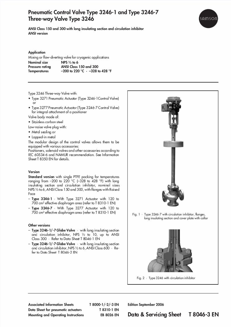
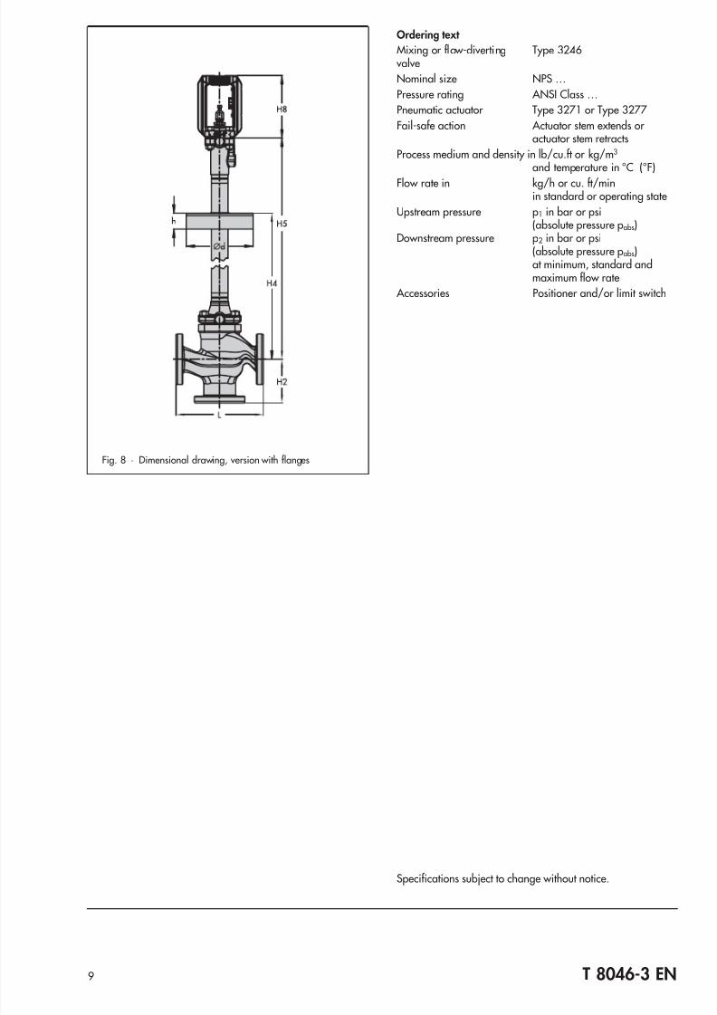
Fig. 1 · Type 3246-7 with circulation inhibitor, flanges,long insulating section and cover plate with collar 

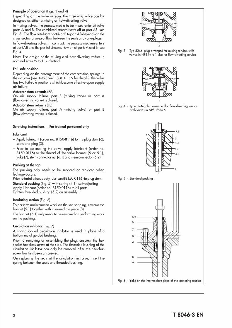
Fig. 2 · Type 3246 with circulation inhibitor 

Pneumatic Control Valve Type 3246-1 and Type 3246-7Three-way Valve Type 3246

 ANSI Class 150 and 300 with long insulating section and circulation inhibitor ANSI version

7/23/2019 3246 T80463EN

http://slidepdf.com/reader/full/3246-t80463en 2/10

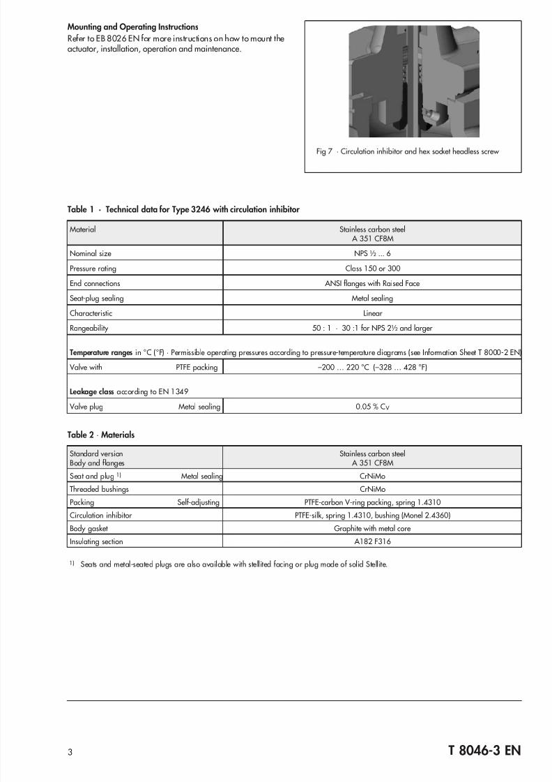
Principle of operation (Figs. 3 and 4)Depending on the valve version, the three-way valve can bedesigned as either a mixing or flow-diverting valve.In mixing valves, the process media to be mixed enter at valveports A and B. The combined stream flows off at port AB (seeFig. 3). The flow rate from port A orB toport AB depends on thecross-sectional area of flow between theseats andvalve plugs.

In flow-diverting valves, in contrast, the process medium entersat port AB and the partial streams flow off at ports A and B (seeFig. 4).

Note: The design of the mixing and flow-diverting valves innominal sizes ½ to 1 is identical.

Fail-safe position

Depending on the arrangement of the compression springs inthe actuator (see Data Sheet T 8310-1 EN for details), the valvehas two fail-safe positions which become effective upon supply air failure:

 Actuator stem extends (FA)On air supply failure, port B (mixing valve) or port A  (flow-diverting valve) is closed.

 Actuator stem retracts (FE)On air supply failure, port A (mixing valve) or port B

(flow-diverting valve) is closed.

Servicing instructions · For trained personnel only 

Lubricant 

– Apply lubricant (order no. 8150-0116) to the plug stem (6),seats and plug (3).

– Prior to assembling the valve, apply lubricant (order no.8150-0116) to the thread of the valve bonnet (5 or 5.1),

 yoke (7), stem connector nut (6.1) and stem connector (6.2).

Packing at the topThe packing only needs to be serviced or replaced whenleakage occurs.Prior to installation, apply lubricant (8150-0116) to plug stem.

Standard packing (Fig. 5) with spring (4.1), self-adjusting Apply lubricant (order no. 8150-0116) to all parts.Tighten threaded bushing (5.2) on assembly.

Insulating section (Fig. 6)

To perform maintenance work on the seat or plug, remove thebonnet (5.1) together with intermediate piece (8).

The bonnet (5.1) only needs tobe removed on performing work on the packing.

Circulation inhibitor (Fig. 7)

 A spring-loaded circulation inhibitor is used in place of abottom metal guided bushing.

Prior to removing or assembling the plug, unscrew the hex socket headless screw at the side. The threaded bushing of thecirculation inhibitor can only be removed after the headlessscrew has first been unscrewed.

On replacing the seals at the circulation inhibitor, insert thespring between the seals and threaded bushing.

2 T 8046-3 EN

Fig. 5 · Standard packing

Fig. 4 · Type 3246, plug arranged for flow-diverting service with valves in NPS 1½ to 6

Fig. 3 · Typ 3246, plug arranged for mixing service, with valves in NPS ½ to 1 also for flow-diverting service

Fig. 6 · Yoke on the intermediate piece of the insulating section

7/23/2019 3246 T80463EN

http://slidepdf.com/reader/full/3246-t80463en 3/10

Mounting and Operating InstructionsRefer to EB 8026 EN for more instructions on how to mount theactuator, installation, operation and maintenance.

3 T 8046-3 EN

Table 1 · Technical data for Type 3246 with circulation inhibitor

Material Stainless carbon steel A 351 CF8M

Nominal size NPS ½ ... 6

Pressure rating Class 150 or 300

End connections ANSI flanges with Raised Face

Seat-plug sealing Metal sealing

Characteristic Linear  

Rangeability 50 : 1 · 30 :1 for NPS 2½ and larger  

Temperature ranges in °C (°F) · Permissible operating pressures according to pressure-temperature diagrams (see Information Sheet T 8000-2 EN)

 Valve with PTFE packing –200 … 220 °C (–328 … 428 °F)

Leakage class according to EN 1349

 Valve plug Metal sealing 0.05 % C V 

Table 2 · Materials

Standard versionBody and flanges

Stainless carbon steel A 351 CF8M

Seat and plug 1) Metal sealing CrNiMo

Threaded bushings CrNiMo

Packing Self-adjusting PTFE-carbon V-ring packing, spring 1.4310

Circulation inhibitor PTFE-silk, spring 1.4310, bushing (Monel 2.4360)

Body gasket Graphite with metal core

Insulating section A182 F316

1) Seats and metal-seated plugs are also available with stellited facing or plug made of solid Stellite.

Fig 7 · Circulation inhibitor and hex socket headless screw 

7/23/2019 3246 T80463EN

http://slidepdf.com/reader/full/3246-t80463en 4/10

Notes on the differential pressure tables

– Values specified in the shaded columns apply to standardcases

– Differential pressures specified in the white columns apply tomaximum pretensioned springs

– Differential pressures in parentheses refer to the values in pa-rentheses in the bench range row 

– The tables apply to both fail-safe positions– The springs in actuators with fail-safe action "Actuator stem

retracts" cannot be pretensioned.

4 T 8046-3 EN

Table 3a · Type 3246 Mixing Valve · C V coefficients and permissible differential pressures · Pressures in bar

Bench range (in bar)for actuators witheffective diaphragm area

120 cm² – –

0.4...2.0(1.2...2.0)

– – – 1.4...2.3 2.1...3.3

240 cm²

0.2...1.0

– –

0.6...3.0(1.8...3.0)

– – –

350 cm²0.4...1.2 0.8...2.4 1.2...3.6

1.4...2.3(1.85...2.3)

2.1...3.3(2.7...3.3)700 cm²

Required supply pressure in bar 1.2 1.6 2.4 (3.2) 3.2 3.6 (4.8) 4.8 3.7 (4.2) 5.4 (6.0)

NPS

C V 

mixing valve

Seat ∅

in (mm)

Rated

travel(mm)

 Actuator 

cm²  ∆

p when p2 = 0 bar 

½ 2.3 · 5

0.94(24)

0.59(15)

120 – – 5.2 – – – 29.3 40

¾ 2.3 · 5 · 7.5 240 5.2 – 14.8 – 24.9 – – –

12.3 · 5

7.5 · 12

350 9.6 23.7 23.7 40 37.8 40 40 40

700 23.7 – – – – – – –

1½and2

7.5 · 12 · 201.22(31)

120 – – – – – – 17 27.1

350 5.2 13.6 13.6 30.5 22.0 40 40 40

700 13.6 – – – – – – –

30 1.49(38)

120 – – – – – – 10.9 17.7  

350 3.1 8.7 8.7 19.9 14.3 31.1 36.7 40

700 8.7 – – – – – – –

2 47 1.89(48)

120 – – – – – – 6.5 10.7  

350 1.6 5.1 5.1 12.1 8.6 19.2 22.7 35

700 5.1 – (40) – (40) – – –

3

30 and 47 1.89(48)

350 1.6 5.1 5.1 12.1 8.6 19.2 22.7 35

700 5.1 – (40) – (40) – – –

702.48(63)

350 – 2.7 2.7 6.7 4.7 10.8 12.9 20

700 2.7 – (23.1) – (35.3) – (36.3) (40)

952.95(75)

350 – 1.7 1.7 4.6 3.1 7.5 8.9 13.9

700 1.7 – (16.1) – (24.7) – (25.5) 37.7  

4

1203.15(80)

1.18(30)

700

1.4 3.9 3.9 9.0 6.4 14 16.6 25.4

1903.93(100)

– 2.3 2.3 5.6 4.0 8.8 10.4 16.1

6

2304.33(110)

– 1.9 1.9 4.5 3.2 7.2 8.6 13.3

3505.12(130)

– 1.2 1.2 3.2 2.2 5.1 6.0 9.4

7/23/2019 3246 T80463EN

http://slidepdf.com/reader/full/3246-t80463en 5/10

5 T 8046-3 EN

Table 3b · Type 3246 Mixing Valve · C V coefficients and permissible differential pressures · Pressures in psi

Bench range (in psi)for actuators witheffective diaphragm area

120 cm² – –

6...30(18...30)

– – – 20...34 30...48

240 cm²

3...15

– –

9...44(26...44)

– – –

350 cm²

6...18 12...35 18...5220...34

(26...34)30...48(39...48)700 cm²

Required supply pressure in psi 18 23 35 (47) 47 52 (70) 70 54 (61) 78 (87)

NPS

C V 

mixing valve

Seat ∅

in (mm)

Rated

travel(mm)

 Actuator 

cm²  ∆

p when p2 = 0 psi

½ 2.3 · 5

0.94(24)

0.59(15)

120 – – 75 – – – 425 580

¾ 2.3 · 5 · 7.5 240 75 – 215 – 355 – – –

12.3 · 5

7.5 · 12

350 139 344 344 580 548 580 580 580

700 344 – – – – – – –

1½and2

7.5 · 12 · 201.22(31)

120 – – – – – – 247 393

350 75 197 197 442 319 580 580 580

700 197 – – – – – – –

30 1.49(38)

120 – – – – – – 158 257  

350 45 126 126 289 207 451 532 580

700 126 – – – – – – –

2 47 1.89(48)

120 – – – – – – 94 155

350 23 74 74 175 125 278 329 508

700 74 – (580) – (580) – – –

3

30 and 47 1.89(48)

350 23 74 74 175 125 278 329 508

700 74 – (580) – (580) – – –

702.48(63)

350 – 39 39 97 68 157 187 290

700 39 – (335) – (512) – (526) (580)

952.95(75)

350 – 25 25 67 45 109 129 202

700 25 – (233) – (358) – (370) 547  

4

1203.15(80)

1.18(30)

700

20 57 57 131 93 203 241 368

1903.93(100)

– 33 33 81 58 128 151 233

6

2304.33(110)

– 28 28 65 46 104 125 193

3505.12(130)

– 17 17 46 32 74 87 136

7/23/2019 3246 T80463EN

http://slidepdf.com/reader/full/3246-t80463en 6/10

6 T 8046-3 EN

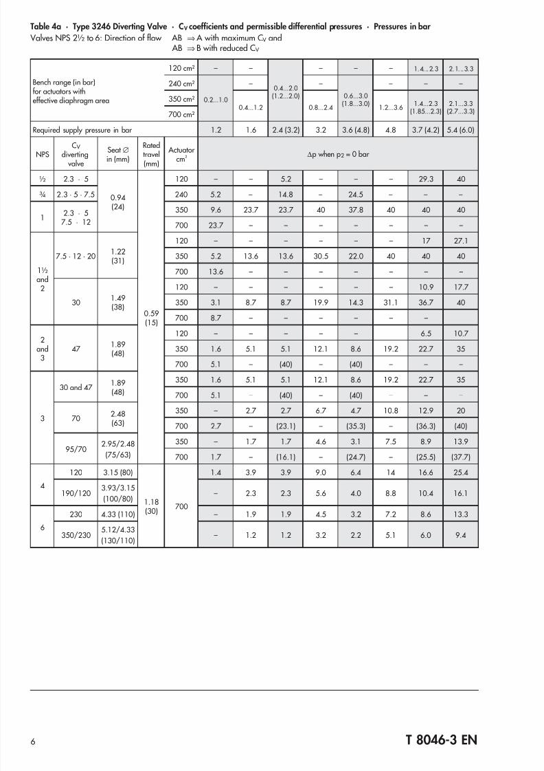
Table 4a · Type 3246 Diverting Valve · C V coefficients and permissible differential pressures · Pressures in bar Valves NPS 2½ to 6: Direction of flow AB   ⇒ A with maximum C V and

 AB   ⇒ B with reduced C V 

Bench range (in bar)for actuators witheffective diaphragm area

120 cm² – –

0.4...2.0(1.2...2.0)

– – – 1.4...2.3 2.1...3.3

240 cm²

0.2...1.0

– –

0.6...3.0(1.8...3.0)

– – –

350 cm²0.4...1.2 0.8...2.4 1.2...3.6

1.4...2.3(1.85...2.3)

2.1...3.3(2.7...3.3)700 cm²

Required supply pressure in bar 1.2 1.6 2.4 (3.2) 3.2 3.6 (4.8) 4.8 3.7 (4.2) 5.4 (6.0)

NPSC V 

diverting valve

Seat ∅in (mm)

Ratedtravel(mm)

 Actuator cm²   ∆p when p2 = 0 bar 

½ 2.3 · 5

0.94(24)

0.59(15)

120 – – 5.2 – – – 29.3 40

¾ 2.3 · 5 · 7.5 240 5.2 – 14.8 – 24.5 – – –

12.3 · 5

7.5 · 12

350 9.6 23.7 23.7 40 37.8 40 40 40

700 23.7 – – – – – – –

1½and2

7.5 · 12 · 201.22(31)

120 – – – – – – 17 27.1

350 5.2 13.6 13.6 30.5 22.0 40 40 40

700 13.6 – – – – – – –

301.49(38)

120 – – – – – – 10.9 17.7  

350 3.1 8.7 8.7 19.9 14.3 31.1 36.7 40

700 8.7 – – – – – –

2and3

47 1.89(48)

120 – – – – – 6.5 10.7  

350 1.6 5.1 5.1 12.1 8.6 19.2 22.7 35

700 5.1 – (40) – (40) – – –

3

30 and 47 1.89(48)

350 1.6 5.1 5.1 12.1 8.6 19.2 22.7 35

700 5.1 – (40) – (40) – – –

702.48(63)

350 – 2.7 2.7 6.7 4.7 10.8 12.9 20

700 2.7 – (23.1) – (35.3) – (36.3) (40)

95/702.95/2.48

(75/63)

350 – 1.7 1.7 4.6 3.1 7.5 8.9 13.9

700 1.7 – (16.1) – (24.7) – (25.5) (37.7)

4

120 3.15 (80)

1.18(30)

700

1.4 3.9 3.9 9.0 6.4 14 16.6 25.4

190/1203.93/3.15

(100/80)– 2.3 2.3 5.6 4.0 8.8 10.4 16.1

6

230 4.33 (110) – 1.9 1.9 4.5 3.2 7.2 8.6 13.3

350/2305.12/4.33

(130/110)– 1.2 1.2 3.2 2.2 5.1 6.0 9.4

7/23/2019 3246 T80463EN

http://slidepdf.com/reader/full/3246-t80463en 7/10

7  T 8046-3 EN

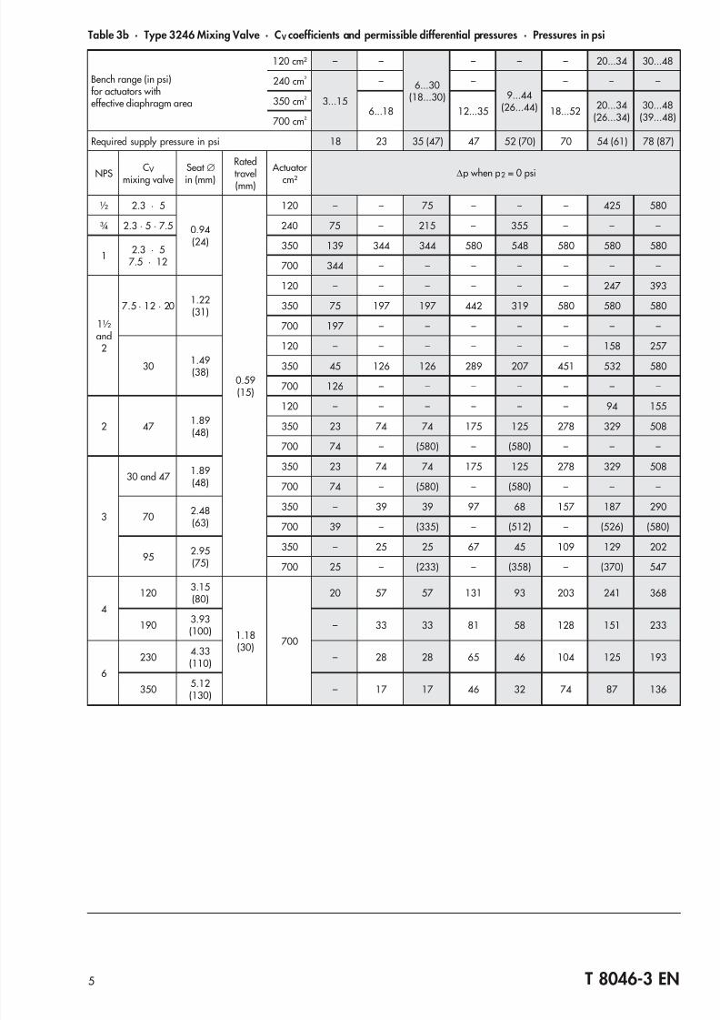
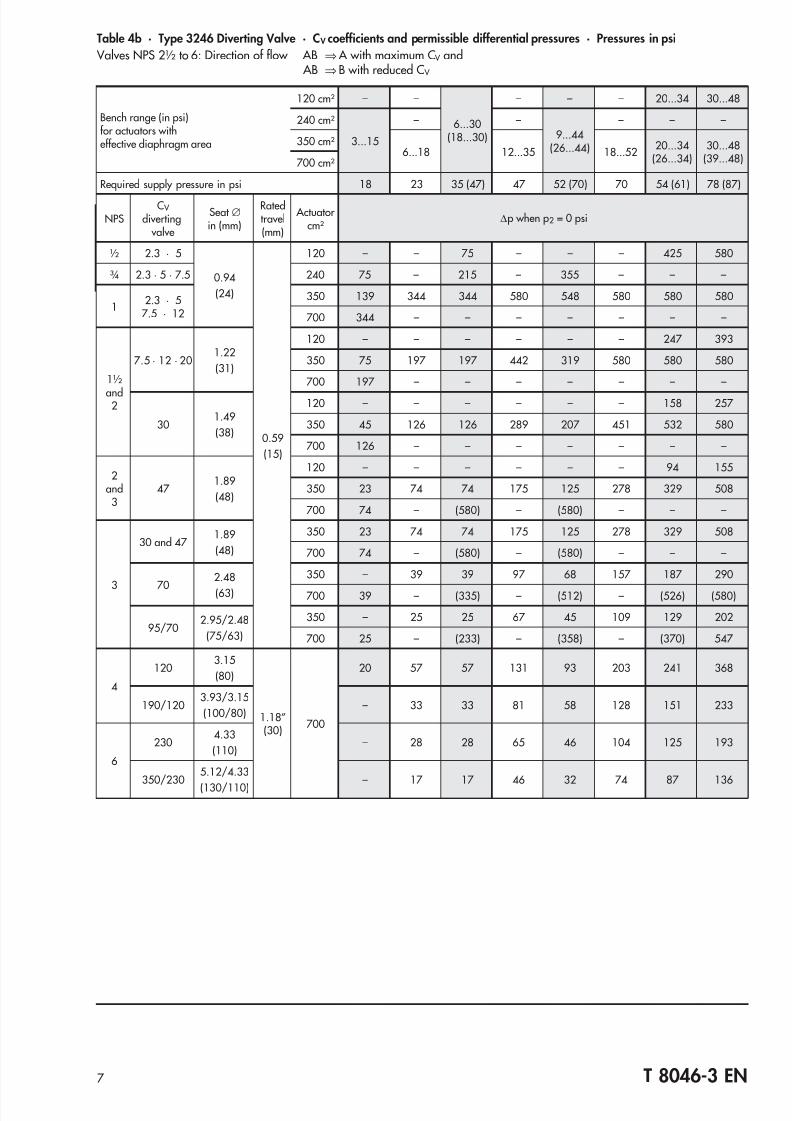
Table 4b · Type 3246 Diverting Valve · C V coefficients and permissible differential pressures · Pressures in psi Valves NPS 2½ to 6: Direction of flow AB   ⇒ A with maximum C V and

 AB   ⇒ B with reduced C V 

Bench range (in psi)for actuators witheffective diaphragm area

120 cm² – –

6...30(18...30)

– – – 20...34 30...48

240 cm²

3...15

– –9...44

(26...44)

– – –

350 cm²6...18 12...35 18...52

20...34(26...34)

30...48(39...48)700 cm²

Required supply pressure in psi 18 23 35 (47) 47 52 (70) 70 54 (61) 78 (87)

NPSC V 

diverting valve

Seat ∅in (mm)

Ratedtravel(mm)

 Actuator cm²

  ∆p when p2 = 0 psi

½ 2.3 · 5

0.94

(24)

0.59

(15)

120 – – 75 – – – 425 580

¾ 2.3 · 5 · 7.5 240 75 – 215 – 355 – – –

12.3 · 5

7.5 · 12

350 139 344 344 580 548 580 580 580

700 344 – – – – – – –

and2

7.5 · 12 · 201.22

(31)

120 – – – – – – 247 393

350 75 197 197 442 319 580 580 580

700 197 – – – – – – –

301.49

(38)

120 – – – – – – 158 257  

350 45 126 126 289 207 451 532 580

700 126 – – – – – – –

2and3

47 1.89

(48)

120 – – – – – – 94 155

350 23 74 74 175 125 278 329 508

700 74 – (580) – (580) – – –

3

30 and 47 1.89

(48)

350 23 74 74 175 125 278 329 508

700 74 – (580) – (580) – – –

70

2.48

(63)

350 – 39 39 97 68 157 187 290

700 39 – (335) – (512) – (526) (580)

95/702.95/2.48

(75/63)

350 – 25 25 67 45 109 129 202

700 25 – (233) – (358) – (370) 547  

4

1203.15

(80)

1.18”(30)

700

20 57 57 131 93 203 241 368

190/1203.93/3.15

(100/80)– 33 33 81 58 128 151 233

6

2304.33

(110)– 28 28 65 46 104 125 193

350/230

5.12/4.33

(130/110) – 17 17 46 32 74 87 136

7/23/2019 3246 T80463EN

http://slidepdf.com/reader/full/3246-t80463en 8/10

8 T 8046-3 EN

Table 5 · Dimensions (inches, mm) and weights for Type 3246 Three-way Valve with long insulating section and circulation inhibitor

 Valve NPS ½ ¾ 1 1½ 2 3 4 6

Length L Class 150 in 7.25 7.25 7.25 8.75 10.0 11.75 13.87 17.75

mm 184 184 184 222 254 298 352 451

Class 300 in 7.50 7.62 7.75 9.25 10.50 12.50 14.50 18.62

mm 190 194 197 235 267 318 368 473

H2 Class 150 in 3.62 3.62 3.62 4.37 5.0 5.87 6.93 8.88

mm 92 92 92 111 127 149 176 225.5Class 300 in 3.76 3.82 3.88 4.63 5.26 6.26 7.24 9.31

95 97 98.5 117.5 133.5 159 184 236.5

H4 Class 150 in 24.05 26.22 26.57 31.26

mm 611 666 675 794

H5 in 31.38 34.13 33.86 36.02 44.49

mm 797 867 860 915 1130

H8 in 6.30 9.06

mm 160 230

Cover plate  ∅

d in 5.98 7.99 10.0mm 152 203 254

h in 1.57 1.57  

mm 40 40

 Weight, approx.lbs 33 44 53 100 190 444

kg 15 20 24 45 86 201

7/23/2019 3246 T80463EN

http://slidepdf.com/reader/full/3246-t80463en 9/10

Ordering text Mixing or flow-diverting Type 3246

 valveNominal size NPS …

Pressure rating ANSI Class …Pneumatic actuator Type 3271 or Type 3277  

Fail-safe action Actuator stem extends or  actuator stem retracts

Process medium and density in lb/cu.ft or kg/m3

and temperature in °C (°F)

Flow rate in kg/h or cu. ft/minin standard or operating state

Upstream pressure p1 in bar or psi(absolute pressure pabs)

Downstream pressure p2 in bar or psi(absolute pressure pabs)at minimum, standard andmaximum flow rate

 Accessories Positioner and/or limit switch

Specifications subject to change without notice.

9 T 8046-3 EN

Fig. 8 · Dimensional drawing, version with flanges

7/23/2019 3246 T80463EN

http://slidepdf.com/reader/full/3246-t80463en 10/10

T 8046-3 EN

SAMSON AG · MESS- UND REGELTECHNIK  Weismüllerstraße 3 · 60314 Frankfurt am Main · Germany Phone: +49 69 4009-0 · Fax: +49 69 4009-1507 Internet: http://www samson de 2

        0        0        6    -        0        9


Recommended