3305 DISTRIBUTION AND UTILISATION VI Term( Applied ) 7 Hours / Week Total Hours : 84 Major Divisions :- Unit I : Distribution. Unit II : Industrial Drives. Unit III : Electric Traction. Unit IV :A) Traction Control. B) Illumination. Unit V : Electric Heating & Welding. UNIT I : DISTRIBUTION 17 Hrs Introduction – classification of distribution systems based on type of supply, character of service, type of construction, number of wires and scheme of connections – types of AC distribution – calculation of voltage at load points on single phase distribution systems( with two load only ) – fed at one end, both ends and ring mains – three phase four wire star connected unbalanced load circuit – problems with resistive load – consequences of disconnection of neutrals in three phase four wire system – calculation of copper required for different distribution systems and comparison between them. Substations : Classifications – advantages and disadvantages of outdoor substations – single line diagram of 11 KV / 440 KV substation – equipments in substations – substation auxiliary supply. Bus - Bar systems : Different types of bus – bar arrangement with sketches – their advantages and disadvantages. UNIT II : INDUSTRIAL DRIVES 16 Hrs Introduction – advantages of electric drives – parts of electric drives( load, motors and control units ) – types of electric drives( industrial, group and multi motor drives ) – nature and classification of load torque – review of different types of motors and their performance characteristics – factors governing the selection of motors – mechanical consideration – standard ratings of motors – classes of load duty cycles – selection of motors for different duty cycles – selection of motors for specific application – electric braking – necessity and advantages of electric braking –rheostatic, dynamic, plugging and electric regenerative braking. Unit III : ELECTRIC TRACTION 17 Hrs Traction systems – comparison and applicability of different traction systems – diesel electric traction – advantages and disadvantages – different types of electrical transmission in diesel electric traction – electric traction - advantages and disadvantages. System of Track Electrification : Different methods of supplying power( rail connected system, over head system ) – over head equipments – catenary and dropper – current collection gear for OHE – bow collector and pantograph collector – different systems of track electrification – DC system – low frequency AC system – high frequency AC system – AC system – composite system( both 1 to 3, AC to DC
Transcript
3305 DISTRIBUTION AND UTILISATION
VI Term( Applied )
7 Hours / Week
Total Hours : 84
Major Divisions :-
Unit I : Distribution. Unit II : Industrial Drives. Unit III : Electric Traction. Unit IV :A) Traction Control.
B) Illumination. Unit V : Electric Heating & Welding.
UNIT I : DISTRIBUTION
17 Hrs
Introduction – classification of distribution systems based on type of supply, character of service, type of construction, number of wires and scheme of connections – types of AC distribution – calculation of voltage at load points on single phase distribution systems( with two load only ) – fed at one end, both ends and ring mains – three phase four wire star connected unbalanced load circuit – problems with resistive load – consequences of disconnection of neutrals in three phase four wire system – calculation of copper required for different distribution systems and comparison between them.
Substations :Classifications – advantages and disadvantages of outdoor substations – single line
diagram of 11 KV / 440 KV substation – equipments in substations – substation auxiliary supply.
Bus - Bar systems :Different types of bus – bar arrangement with sketches – their advantages and
disadvantages.
UNIT II : INDUSTRIAL DRIVES 16 Hrs
Introduction – advantages of electric drives – parts of electric drives( load, motors and control units ) – types of electric drives( industrial, group and multi motor drives ) – nature and classification of load torque – review of different types of motors and their performance characteristics – factors governing the selection of motors – mechanical consideration – standard ratings of motors – classes of load duty cycles – selection of motors for different duty cycles – selection of motors for specific application – electric braking – necessity and advantages of electric braking –rheostatic, dynamic, plugging and electric regenerative braking.
Unit III : ELECTRIC TRACTION 17 Hrs
Traction systems – comparison and applicability of different traction systems – diesel electric traction – advantages and disadvantages – different types of electrical transmission in diesel electric traction – electric traction - advantages and disadvantages.
System of Track Electrification :Different methods of supplying power( rail connected system, over head system ) – over
head equipments – catenary and dropper – current collection gear for OHE – bow collector and pantograph collector – different systems of track electrification – DC system – low frequency AC system – high frequency AC system – AC system – composite system( both 1 to 3, AC to DC
systems ) - advantages and disadvantages of 25 KV 50 Hz AC systems – necessity of booster transformer – different methods of connecting booster transformer – neutral sectioning.
Traction mechanics :Units and notations used in traction mechanics – speed time curves( main line, sub urban
and urban ) – simplified speed time curve – average speed – scheduled speed – tractive effort – problems using simplified speed time curve, tractive effort and power requirement.
Traction motors :Desirable characteristics of traction motors suitable for traction purpose( DC series, AC
series motor, repulsion motor, induction motor and linear induction motor ).
Unit IV :- A) TRACTION CONTROL 17 Hrs
Necessity of control equipments – principle of control of DC traction motors – various methods used for starting and speed control of DC traction motors – rheostatic control – series parallel control – shunt transition – bridge transition – multiple unit control – drum control – contactor type bridge transition – thyristor control – requirements of braking systems – pneumatic braking – regenerative braking applied to traction.
B) IlluminationDefinition and units of different terms used in illumination – solid angle, light, luminous flux,
luminous intensity, candle power, illumination, MSCP, MHCP, MHSCP – reduction factor – luminance or brightness – glare – lamp efficiency – space height ratio – depreciation factor and maintenance factor – utilization factor or co – efficient of utilization - waste light factor – absorption factor – beam factor – reflection factor – essentials of good lighting system – laws of illumination – problems – sources of light – arc lamp – incandescent lamp – halogen lamp – discharge lamps – gaseous discharge lamps – sodium vapour lamp – high pressure mercury vapour lamp – neon tube – flourescent tube – effect of voltage variation – energy saving consideration for flourescent lamp – lamp fittings and lighting systems – illumination level required for various applications – factors to be considered while designing lighting scheme.
Unit V :- ELECTRIC HEATING AND WELDING 17 Hrs
Electric Heating :Introduction – advantages of electric heating – classification of heating
methods based on temperature range – modes of heat transfer – classification of electric heating – power frequency electric heating( direct resistance heating, indirect resistance heating, infra-red heating and arc heating ) – high frequency supply electric heating ( induction heating, eddy current heating and dielectric heating ).
Resistance Ovens and Furnaces :Requirements of heating element materials – commonly used heating element materials –
resistance furnaces for special purposes – temperature control of resistance furnaces – type of arc furnaces – direct arc furnace – indirect arc furnace – submerged arc furnace – power supply and control for arc furnaces – reasons for employing low voltage and high current supply. Induction furnaces :
Direct core type – indirect core type – coreless induction furnace – method of obtaining power supply for coreless induction furnace.
Welding :Introduction for welding – types of electrical welding.
Carbon arc welding – metal arc welding – atomic hydrogen arc welding – inert gas metal arc welding – submerged arc welding.
Radiation welding :Ultra sonic welding - electron beam welding – LASER beam welding.
Requirements of good welding :
Preparation of work for welding – electrodes used for welding – electric welding equipments – control of current flow – welding transformers – comparison of arc welding and resistance welding.
Reference Books :
Sl.No. Name of the Book Author Publisher
1
2
3
4
5
6
7
8
9
A Course in Electrical Power
Electric Power
A Text Book in Electric Power
Modern Electric Traction
Electrical Power Distribution System
Fundamentals of Electrical Drives
Utilisation of Electric Power
Electric Drives
Industrial Drives And Control
JB. Gupta
S.L. Uppal
1. Soni 2. Gupta 3. Bhatnagar
H. Partab
A.S. Pabla
GK. Dubey
N.V. Suryanarayana
Vedam Subramaniam
TTTI. Chennai.
Katson Publishing House, New Delhi.
Khanna Publishers, New Delhi
Dhanpat Rai & Sons, Delhi
Dhanpat Rai & Sons, Delhi
Tata Mc.Graw Hill Publishing Co., New Delhi
Narosa Publishing House, New Delhi.
Tata Mc.Graw Hill Publishing Co., New Delhi.
New Age International,New Delhi
Tata Mc.Graw Hill Publishing Co., New Delhi.
3306 MICRO CONTROLLERS
VI Term( Applied )
6 Hours / Week
Total Hours : 72
Major Divisions:
Unit I ArchitectureUnit II Instructions IUnit III Instructions IIUnit IV Timer / Counter And InterruptUnit V Peripherals
Unit I – ARCHITECTURE
15 Hrs
Evolution of Microprocessor, definition of terms used in Microprocessor, Architecture of 8085 (Block diagram) – Basic ideas on operation of Microprocessor based systems – Difference between micro processor and micro controllers. Advantages of micro controllers. Architecture of 8051 micro controller. (Block diagram). Programme counter and Data pointer A and B CPU Registers. Flags and the programme Status Word Internal Memory, Internal Ram, the Stack and Stack Pointer, Special Function registers. Internal ROM - External Memory – Input/Output Pins, Ports.
Unit II - INSTRUCTIONS I
14 Hrs
Addressing methods – Immediate Addressing modes, Register addressing modes, Direct addressing modes, Indirect addressing modes - Data transfer instructions – Code Memory Read - Only Data Moves – Push and Pop Opcode - Data exchanges. (simple examples may be used). Logical operations – Byte and Bit level operations, internal RAM Bit addresses - SFR Bit addresses. Bit level Boolean operations - Rotate and Swap operations.
Unit III - INSTRUCTIONS II
14 Hrs
Arithmetic instructions flags – Addition - unsigned and signed addition – Subtraction - unsigned and signed subtraction – Multiplication - Division – Detailed Arithmetic – Jump and Call
Instructions – Interrupts and Returns. Details study of assembler ASM51- Simple programmes such as Addition of an 8 bit array, 8 bit multiplication, 8 bit division.
Unit IV – TIMER/COUNTER AND INTERRUPT
15 Hrs
Timer/Counter operations – Different modes of Timer/Counter – Simple program using timer and counter – Timer interrupt – Counter interrupts – External Interrupts - Simple programme using timer/counter interrupt, External Interrupts – Serial port operation - Different Modes of serial data transmission – Developing programme using the serial port mode II.
Unit V - PERIPHERALS
14 Hrs
8255 Programmable Peripheral Interface Rs232C serial port signal details – ADC 0808 – 8279 Programmable Key Board and Display interface Signal details – Modes of operation – Interfacing & segment LED with 89C51 interfacing 1 x 16 line LCD Display. Interfacing of Stepper motor – Interfacing of D.C motor.
Reference Books :
Sl.No. Name of the Book Author Publisher
1
2
The 8051 Micro controller Architecture. Programming & Applications
Using Assembly Language
Kenneth J. Ayala
Allen Wyatt Sr.
Penram International
Prentice Hall of India (P) Ltd., New Delhi.
3403 A - COMPUTER HARDWARE SERVICING
( VI Term Diversified )6 Hours / Week
Total Hours : 72
Major Divisions
UNIT I : PC Hardware – Overview.UNIT II : Memory and Memory Devices. UNIT III: Keyboard, Monitor, Port and SMPS.UNIT IV: Input / Output Devices.UNIT V : PC Installation and Servicing.
UNIT: I PC HARDWARE – OVERVIEW
15 Hrs
Evolution – PC through Pentium – back ground – specification – comparison chart of the processors.Personal computer system – block diagram – PC system unit – layout – Tower model, flip-top model – mother board and daughter boards – SMPS – front panel controls – display unit – key board – rear side connectors and the purpose.Mother board layout – Functional blocks of 286/386/486 and Pentium systems – mother board memory – I/O expansion slots – RTC, integrated mother board layout.Bus architecture system – PC-BUS, ATBUS/ISA, EISA, MCA, VESA and PCI bus.Basics of BIOS – ROM BIOS organisation and services – BIOS for DOS and Windows – setup programs.
UNIT: II MEMORY AND MEMORY DEVICES
15 Hrs
Data storage & retrieval methods in Level 2 cache ; EDO RAM; PC’s memory organization - low memory, high memory, 64 KB limits, extended memory, virtual memory, expanded memory, cache memory, and DMA channels - memory packages – Single Inline Memory Module, Single Inline Package; Disk organisation in DOS – Sectors, Clusters, DOS Boot Record, FAT, directory structure.
Floppy Disks Basis – Tracks Sectors; Types – 51/4”,3.5”; capacity; disk parts, disk formatting; data recording; MFM recording - floppy disk drive – capacity, head movement, head coils, spindle motors, installation and configuration - FDC – functions - signals, block diagram , interfacing a drive.
Hard disk basics – tracks ,cylinders, sectors, heads, drive sub assemblies – head actuators - spindle motor, media, logic board, hard disk capacity, data storage and retrieval mechanism; hard disk types – IDE, SCSI, variations and limitations, installation of hard disk – configuring, formatting and partitioning.
CDROM Types – Audio, Video, DVD, Data CDs - Reading and writing mechanism, Storage capacity, CD Drive mechanisms; sub Assemblies - Installation.
Basics of digital sound - audio compression and decompression - MPEG audio compression - sound blaster card – block diagram, explanation; the input and outputs of sound card; connecting a MIDI,CD-ROM video on the PC-basics, capturing – still, motion, compression methods - MPEG & JPEG; video blaster card – block diagram.
The display - video basics - the CRT scanning methods – monochrome CRT - color CRT – Block diagram of VGA monitor - display adaptors – CGA, EGA, SVGA - card layout - monitor features - power management – signalling - creating the screen image - video attributes - character/graphics display - monitors and resolutions.
The serial port - parallel port - game port - signals and connector specifications - block diagram.SMPS – operation, output voltage levels, UPS – offline, online operations - stabilizers.
Unit IV INPUT / OUTPUT DEVICES
14 Hrs
The mouse - signals, connection, operation, installation. Scanner – types - Flat-bed, drum type; colour and gray - installation. Digitizer – operation, connection - digital camera – connection, operation.
Dot-Matrix Printer - Printer sub assemblies - block diagram, control electronics, printer mechanism - self test - various printing options - printer installation.
Laser Printer - Block diagram, printers sub-assemblies - interface controller, input Interface - CPU, printer RAM - mechanism – printing an image, data Input - drum preparation - paper feed mechanism - image formation - image transfer -Fusing the image - self test - use of toner cartridges - installation
Configuring the mother board – all in one motherboards - identifying the connectors & cables - adding memory modules - upgrading the CPU - BIOS setup program - various setup options - configuring the IDE card.
Power-On-Self-Test, IPL hardware, POST test sequence; POST error messages.
Trouble shooting the motherboard – problem diagnosis, normal checks, power supply, clock signal check, keyboard check, speaker check; trouble shooting the keyboard; verifying with diagnostic softwares - checking the connectors & cables.
Trouble shooting floppy disk drives and hard disk - problem diagnosis, typical problems and trouble shooting - checking the CMOS setup.
Reference Books:
Sl.No. Name of the Book Author Publisher
1.
2.
3.
4.
5.
6.
IBM PC and Clones
Servicing & Supporting IBM PC’s & Compatibles
Monitor Repair made Simple
Computer Installation and Servicing Peter Norton’s Inside the PC
The Computer PC upgrade & Maintenance Guide
Govindarajulu
Tony Jomaa
D. Balasubramanian
Peter Norton
Mark Minasi
Tata McGraw Hill Publishing Company, New Delhi
Galgotia Publications (P) Ltd., New Delhi.
Pustak Mahal, New Delhi
Tata McGraw Hill Publishing Company, New DelhiPrince - Hall Computer Publishing Pvt., Ltd., New Delhi.BPB Publications, New Delhi.
3403 B - POWER ELECTRONICS
VI Term ( Diversified ) 6 Hours / Week
Total Hours : 72
Major Divisions
UNIT I : Thyristor Family And Trigger Circuits.UNIT II : Phase Controlled Rectifier.UNIT III: Commutation Circuits and Inverter Circuits.UNIT IV: Choppers and Cycloconverters.UNIT V : Control of Dc and Ac Drives.
UNIT I THYRISTOR FAMILY AND TRIGGER CIRCUITS 15 Hrs
Thyristor family – Silicon Controlled Rectifier SCR – Symbol, working, characteristic, holding current, latching current, dv/dt, di/dt ratings, thermal ratings (junction temperature, transient thermal resistance), gate protection – Insulated gate bipolar transistor (IGBT) – Symbol, working, characteristic and equivalent circuit – Symbol, working and characteristics of DIAC, TRIAC, SUS, SCS, SBS, LASCR, and GTO – Symbol, working, oscillator circuit of Programmable UJT.
Gate trigger circuits – DC triggering, AC triggering, Pulse gate triggering – Pulse transformer in trigger circuit – Electrical isolation by opto isolator - Resistance firing circuit and waveform – Resistance capacitor firing circuit and waveform, Synchronized UJT triggering (ramp triggering) – Ramp and pedestal trigger circuit for ac load.
UNIT II PHASE CONTROLLED RECTIFIER
14 Hrs
Half wave controlled rectifier with resistance load, resistance inductive load, effect of free wheeling diode with waveform – Single phase fully controlled bridge with RL load – average dc
output voltage – rectifier mode - Inverter mode – waveform for α = 60° - input power factor (definition and expression) – Single phase half controlled bridge with RL load – average dc output voltage – waveform – input power factor (definition and expression).
3 phase fully controlled bridge with RL load - firing sequence – average dc output – voltage and current waveform with respect to line to line supply voltage – 3 phase half controlled bridge with RL load – average dc output – continuous conduction mode – discontinuous conduction mode – waveform.
Complete protection of converter – including surge current and voltage, dv/dt and di/dt protection.
UNIT III COMMUTATION CIRCUITS AND INVERTER CIRCUITS 14 Hrs
SCR turn off methods – Natural commutation – Forced commutation – Class A, Class B, Class C, Class D, Class E, and Class F.
Inverter classifications – 1φ series inverter – basic parallel inverter – voltage and current waveform - 1φ full bridge inverter - 1φ McMurray (auxiliary commutated) full bridge inverter - 1φ McMurray Bedford (complementary commutated) full bridge inverter - 1φ inverter output voltage control by Pulse Width Modulation control (dc reference) – Sinusoidal Pulse Width Modulation for 1φ circuit – Basic 3 phase bridge inverter with 120° conduction mode – circuit, trigger sequence, waveform and applications.
UNIT IV CHOPPERS AND CYCLOCONVERTERS 14 Hrs
Principle of Chopper – control strategies (time-ratio & current limit control) – Stepup chopper – Jones chopper – Morgan chopper – AC chopper – chopper control of dc series motor – voltage commutated chopper – current commutated chopper – load commutated chopper.
Cycloconverter – basics - 1φ to 1φ cycloconverter – input, output waveform with resistive load - 1φ bridge type cycloconverter - 3φ to 3φ cycloconverter – schematic diagram, basic circuit.
UNIT V CONTROL OF DC AND AC DRIVES 15 Hrs
Basic dc motor speed equation – operating region of armature voltage control and field current control – constant torque and constant HP regions – Schemes for separately excited dc motor speed control – single phase full converter drives – circuit, operating quadrants, waveform – power factor improvement in phase controlled converter – phase angle control, semiconverter operation of full converter, asymmetrical firing – Three phase full converter drives – operation and waveform – Chopper fed dc series motor.
closed loop control of dc drives – basic block diagram – Phase locked loop (PLL) control of
dc drives – block diagram – four quadrant control of dc motor using dual converter.
Torque-Speed characteristic of 3 phase induction motor – Speed control of induction motor – Stator voltage control, variable frequency control – necessity of maintaining v/f ratio constant – rotor resistance control – inverters for variable voltage and frequency control – single quadrant closed loop speed control – speed control by rotor resistance for slip ring motors – Static Scherbius drive (slip power recovery scheme) – space vector control scheme.
Reference Books:
Sl.No. Name of the Book Author Publisher
1.2.
3.
4.
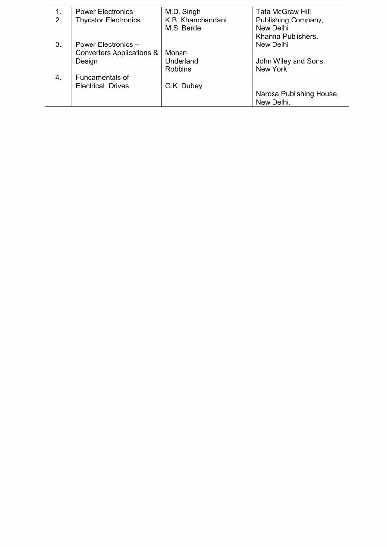
Power ElectronicsThyristor Electronics
Power Electronics – Converters Applications & Design
Fundamentals of Electrical Drives
M.D. Singh K.B. KhanchandaniM.S. Berde
MohanUnderlandRobbins
G.K. Dubey
Tata McGraw Hill Publishing Company, New DelhiKhanna Publishers., New Delhi
John Wiley and Sons, New York
Narosa Publishing House, New Delhi.
3403 C – PROGRAMMABLE LOGIC CONTROLLER
VI Term ( Diversified )
6 Hours / Week
Total Hours : 72
Major Divisions
UNIT I : Introduction To PLC.UNIT II : Programming Programmable Controller, Introduction To Logic. UNIT III: AB PLC, Basic Instruction, Timer And Counter Instruction.UNIT IV: Comparison Instructions, Math Instructions, Logical Instructions.UNIT V : Ladder Logic Diagram For Control Circuits
UNIT I : INTRODUCTION TO PLC.
15 Hrs
Definition of PLC – Block diagram of PLC and parts of PLC – Operation of PLC – Detailed description of PLC and connectivity – Communication – Memory – PLC Scan – Input interfacing – Output interfacing – Input modules – Output modules- Introduction to modular PLC – Advantages of using PLC over conventional electrical relay.
UNIT II : PROGRAMMING PROGRAMMABLE CONTROLLER14 Hrs
Hand held programming terminals – PCs and
PLC programming – Industrial computers – IEC1131 – 3 programming standard – Ladder diagram (LD) – Functional block diagram (FBD) – Instructional list (IL) – Structure text (ST) – Sequential functional chart. Introduction to logic Conventional wiring diagram versus PLC ladder logic – Logic functions – AND logic, OR logic two input and three inputs with truth table – NOT logic – Exclusive OR logic – Combinational logic – Priority of logic elements.
UNIT III : AB PLC
14 Hrs Basic Instruction
Normally open (or) Examine ON – Normally closed (or) Examine OFF – One shot instruction – Latch output coil unlatch coil
Timer and Counter instructionON delay timer instruction (TON) – OFF delay timer instruction (TOFF) – Retentive timer
instruction (RTO) – Counter up instruction (CTU) – Counter down instruction (CTD) – Reset instruction (RES).
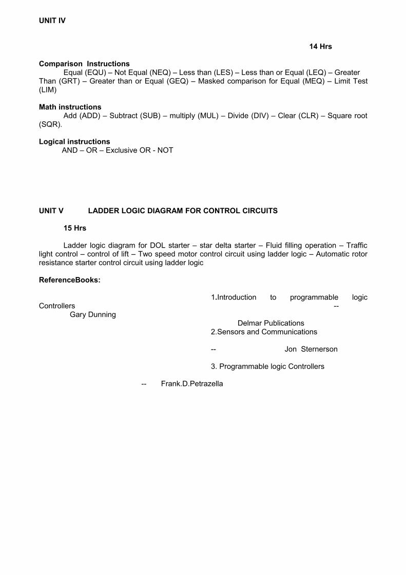
UNIT IV
14 Hrs Comparison Instructions
Equal (EQU) – Not Equal (NEQ) – Less than (LES) – Less than or Equal (LEQ) – GreaterThan (GRT) – Greater than or Equal (GEQ) – Masked comparison for Equal (MEQ) – Limit Test (LIM)
Logical instructions AND – OR – Exclusive OR - NOT
UNIT V LADDER LOGIC DIAGRAM FOR CONTROL CIRCUITS
15 Hrs
Ladder logic diagram for DOL starter – star delta starter – Fluid filling operation – Traffic light control – control of lift – Two speed motor control circuit using ladder logic – Automatic rotor resistance starter control circuit using ladder logic
ReferenceBooks:
1.Introduction to programmable logic Controllers --
Gary Dunning Delmar Publications
2.Sensors and Communications
-- Jon Sternerson
3. Programmable logic Controllers
-- Frank.D.Petrazella
3403 D - PROGRAMMING IN C++ & ITS APPLICATIONS
VI Term ( Diversified )6 Hours / Week
Total Hours : 72
Major Divisions
UNIT I : Introduction To Object Oriented Programming And C++ Programming.UNIT II : Functions, Classes And Objects. UNIT III: Constructors, Destructors And Operator Overloading.UNIT IV: Inheritance, Pointers And Virtual Functions.UNIT V : Console I/O And File Management.
UNIT: I INTRODUCTION TO OBJECT ORIENTED PROGRAMMING AND C++ PROGRAMMING 15 Hrs
Problems in software development - software evolution - procedure oriented programming - object oriented programming paradigm - basic concepts of object oriented programming - benefits of OOP - object oriented languages - applications of OOP.
Features and applications of C++ - structure of C++ programs – cin and cout objects – creating the source file – compiling and linking.
Keywords - identifiers; basic data types - user defined data types - derived data types; symbolic constants - type compatibility - declaration of variables - dynamic initialization of variables - reference variables - operators in C++ - scope resolution operator - member dereferencing operators - memory management operators – manipulators - type cast operator - expressions and implicit conversions - operator overloading - operator precedence.
goto statement - if and if…else statement - while and do…while statements - switch statement - for statement.
UNIT: II FUNCTIONS, CLASSES AND OBJECTS
15 Hrs
The main () function - functions prototype - call by reference, return by reference, inline function; default arguments - const arguments - functions overloading.
Structures and classes; classes – specifying a class - defining member functions - nesting of member functions - private member functions - arrays within a class - memory allocation for objects, static data member - static member functions.
Arrays of objects - objects as function arguments - friendly functions - returning objects - constant member functions - pointers to the members.
UNIT: III CONSTRUCTORS, DESTRUCTORS AND OPERATOR OVERLOADING14 Hrs
Constructors without parameters - constructors with parameters - multiple constructors - constructors with default arguments - dynamic initialization of objects - copy constructors - dynamic constructors - destructors.
Operator loading - overloading unary operators - overloading binary operators with friends - manipulation of strings using operators; rules for overloading operators.
Conversion of basic data types to class and class to basic data types - conversion of one class to another class.
UNIT: IV INHERITANCE, POINTERS AND VIRTUAL FUNCTIONS14 Hrs
Inheritance - Defining derived classes - single inheritance - making a private member
inheritable - multi-level inheritance - multiple inheritance - hierarchy inheritance -hybrid inheritance - virtual base classes - abstract classes - constructors in derived classes - member classes - nesting of classes – polymorphism.
Pointers to objects - pointers to derived classes -Virtual functions - Rules for virtual functions - pure virtual functions.
Classes for file stream operations - opening and closing a file - detecting end of files - file modes - file pointers and their manipulators - sequential input and output operations - updating a file - error handling.
Reference Books :
Sl.No. Name of the Book Author Publisher
1.
2.
Object Oriented Programming with C++ Schaum’s outlines Programming with C++
E. BalagurusamyJohn Hubbard
Tata McGraw Hill Publishing Company, New Delhi ---- do ---
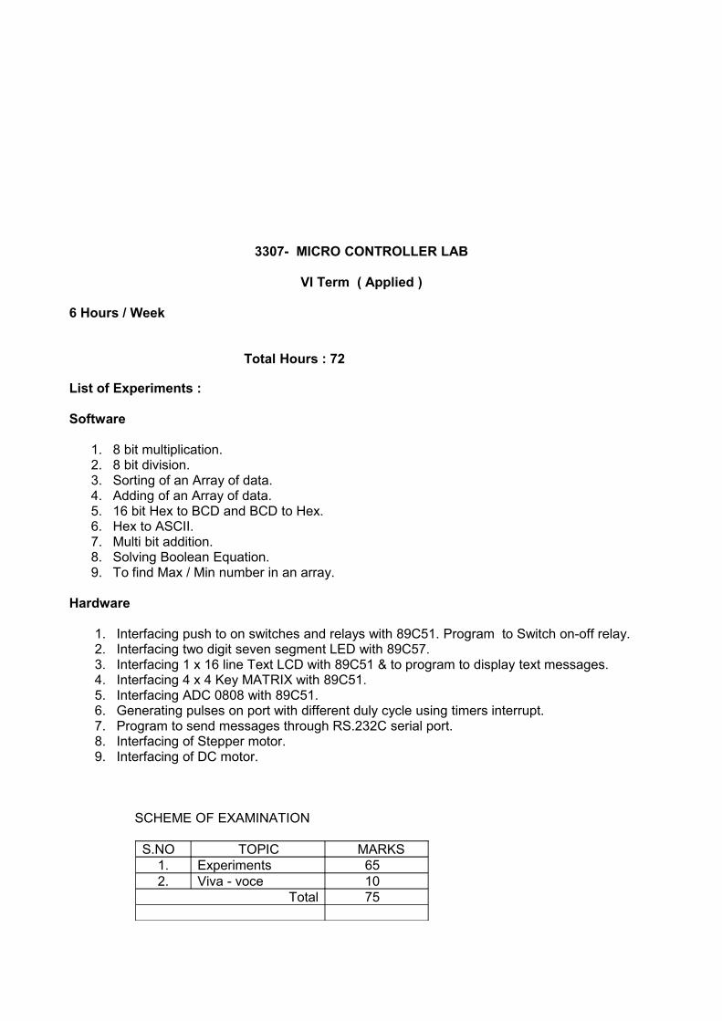
3307- MICRO CONTROLLER LAB
VI Term ( Applied )
6 Hours / Week
Total Hours : 72
List of Experiments :
Software
1. 8 bit multiplication. 2. 8 bit division. 3. Sorting of an Array of data.4. Adding of an Array of data. 5. 16 bit Hex to BCD and BCD to Hex. 6. Hex to ASCII.7. Multi bit addition.8. Solving Boolean Equation.9. To find Max / Min number in an array.
Hardware
1. Interfacing push to on switches and relays with 89C51. Program to Switch on-off relay.2. Interfacing two digit seven segment LED with 89C57.3. Interfacing 1 x 16 line Text LCD with 89C51 & to program to display text messages.4. Interfacing 4 x 4 Key MATRIX with 89C51. 5. Interfacing ADC 0808 with 89C51.6. Generating pulses on port with different duly cycle using timers interrupt.7. Program to send messages through RS.232C serial port.8. Interfacing of Stepper motor.9. Interfacing of DC motor.
1. To study the important jumper settings for changing the CPU ; Memory size etc. in a givenMother board.
2. Installing and configuring FDD in a computer system. Using BIOS setup program to Configure an FDD. b) Floppy drive diagnostics/servicing.
3. HDD Installation: a) Installing a Hard disk b) Configure using CMOS – setup Program.c) Partitioning using FDISK program. D) Formatting Hard disk drives.
4. CD Drive Installation: a) Installation a CD – ROM drive for DOS/Windows mode. b) configuring using device drivers.
5. Printer Installation and Servicing a) Installing a Dot Matrix Printer b) Installing a LaserPrinter / Ink Jet Printer. c) Printer troubleshooting for “Cable fault, Printer head fault”
6. Use of AT diagnostic software to study and diagnose the Motherboard Problems Using AT Diags, Norton Utilities for Windows.
7. Trouble shooting important Disk Oriented Problems a) Floppy disk won’t boot.b) Eliminating the cross links. C) Reviving a floppy disk.
8. a) Study of SVGA card b) SVGA monitor servicing.9. Identification of front panel indicators, switches in a computer system for Flip – Flop and
Tower case Model computers & Identification of the rear side connectors available in aComputer system.
10. Familiarising the computer system layout: Making the positions of SMPS, Motherboard,FDD/HDD/CD and ad-on cards in both Tower/Flip Flop models.
11. To draw the layout of a 486/Pentium Motherboards and marking the following items in it.CPU used, RAM, Cache, Xtal, Cooling fan, I/O slots, O/P parts available.
12. Study of CMOS – setup program. A) Changing standard settings. b) changingAdvanced settings.
13. Study of IDE card: a) to draw the layout b) to study the various connections available.c) to study the jumper settings.
14. Familiarising Important DOS commands like SCANDISK, FDISK15. Networking of computers.16. Checking the signal levels at different points of power supply.17. Checking and tabulating the address, data and control signals of CPU using logic probe.18. Use of system error code to identify problems.
1. Line synchronized UJT trigger circuit.2. DIAC – TRIAC lamp control circuit.3. Characteristic IGBT and GTO.4. Ramp and Pedestal trigger circuit for ac load.5. Single phase half controlled bridge.6. Single phase fully controlled bridge.7. SCR commutation circuits.8. Basic series inverter circuits.9. DC chopper control circuit (any one).10. 1φ to 1φ cycloconverter11. Study of IGBT based UPS.12. DC shunt motor control circuit.13. Universal motor control circuit.14. Closed loop control of dc motor.15. Closed loop control of ac motor.
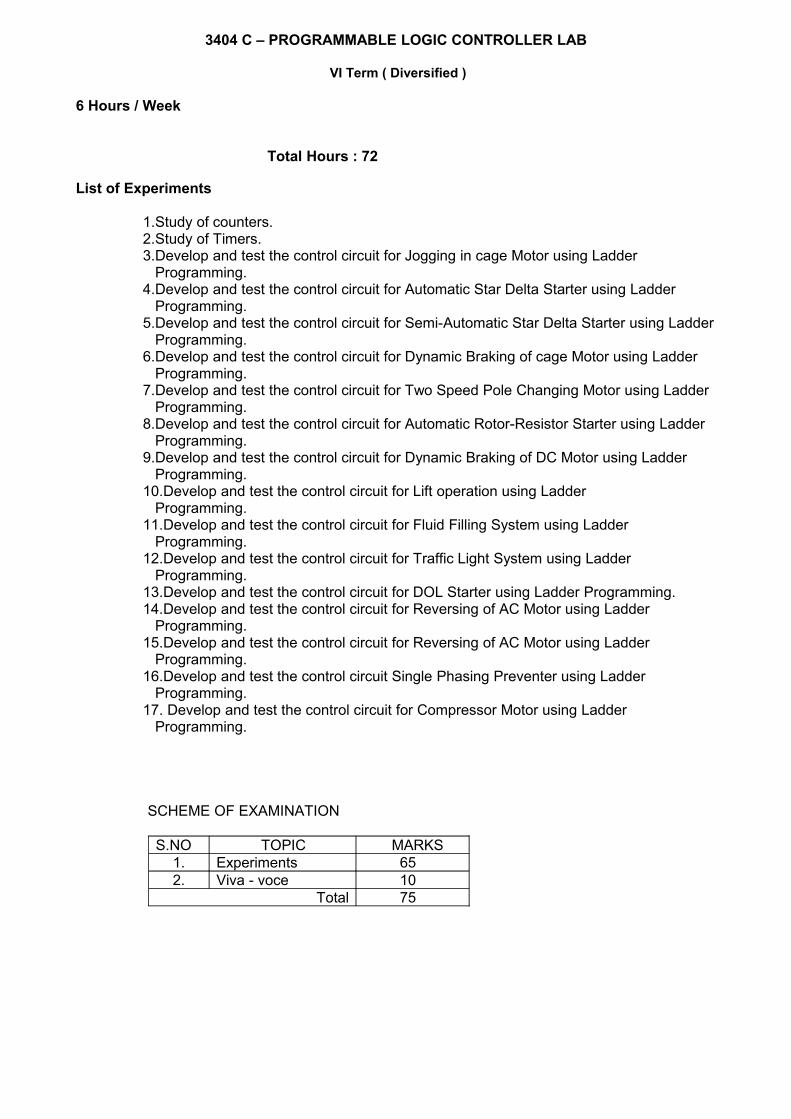
1.Study of counters.2.Study of Timers.3.Develop and test the control circuit for Jogging in cage Motor using Ladder Programming.4.Develop and test the control circuit for Automatic Star Delta Starter using Ladder Programming.5.Develop and test the control circuit for Semi-Automatic Star Delta Starter using Ladder Programming.6.Develop and test the control circuit for Dynamic Braking of cage Motor using Ladder Programming.7.Develop and test the control circuit for Two Speed Pole Changing Motor using Ladder Programming.8.Develop and test the control circuit for Automatic Rotor-Resistor Starter using Ladder Programming.9.Develop and test the control circuit for Dynamic Braking of DC Motor using Ladder Programming.10.Develop and test the control circuit for Lift operation using Ladder Programming.11.Develop and test the control circuit for Fluid Filling System using Ladder Programming.12.Develop and test the control circuit for Traffic Light System using Ladder Programming.13.Develop and test the control circuit for DOL Starter using Ladder Programming.14.Develop and test the control circuit for Reversing of AC Motor using Ladder Programming.15.Develop and test the control circuit for Reversing of AC Motor using Ladder Programming.16.Develop and test the control circuit Single Phasing Preventer using Ladder Programming.17. Develop and test the control circuit for Compressor Motor using Ladder Programming.
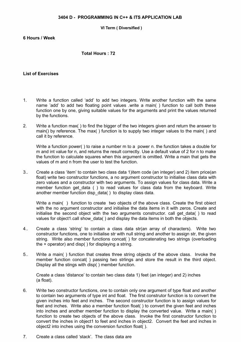
1. Write a function called ‘add’ to add two integers. Write another function with the same name ’add’ to add two floating point values .write a main( ) function to call both these function one by one, giving suitable values for the arguments and print the values returned by the functions.
2. Write a function max( ) to find the bigger of the two integers given and return the answer to main() by reference. The max( ) function is to supply two integer values to the main( ) and call it by reference.
Write a function power( ) to raise a number m to a power n. the function takes a double for m and int value for n, and returns the result correctly. Use a default value of 2 for n to make the function to calculate squares when this argument is omitted. Write a main that gets the values of m and n from the user to test the function.
3.. Create a class ‘item’ to contain two class data 1)item code (an integer) and 2) item price(an float) write two constructor functions, a no argument constructor to initialise class data with zero values and a constructor with two arguments. To assign values for class data. Write a member function get_data ( ) to read values for class data from the keyboard. Write another member function disp_data( ) to display class data.
Write a main( ) function to create two objects of the above class. Create the first obiect with the no argument constructor and initialise the data items in it with zeros. Create and initialise the second object with the two arguments constructor. call get_data( ) to read values for object1.call show_data( ) and display the data items in both the objects.
4.. Create a class ‘string’ to contain a class data str(an array of characters). Write two constructor functions, one to initialise str with null string and another to assign str, the given string. Write also member functions concat( ) for concatenating two strings (overloading the + operator) and disp( ) for displaying a string.
5.. Write a main( ) function that creates three string objects of the above class. Invoke the member function concat( ) passing two strlings and store the result in the third object. Display all the stings with disp( ) member function.
Create a class ‘distance’ to contain two class data 1) feet (an integer) and 2) inches (a float).
6. Write two constructor functions, one to contain only one argument of type float and another to contain two arguments of type int and float. The first construtor function is to convert the given inches into feet and inches. The second constructor function is to assign values for feet and inches. Write also a member function float( ) to convert the given feet and inches into inches and another member function to display the converted value. Write a main( ) function to create two objects of the above class. Invoke the first constructor function to convert the inches in object1 to feet and inches in object2. Convert the feet and inches in object2 into inches using the conversion function float( ).
7. Create a class called ‘stack’. The class data are
1) number (an array of integers) and 2) top (an integer). Write a member function push( ) to store the given integer in the array ‘number’ using top as an index. Write another member function pop( ) to return the last integer in the array ‘number’ using top as an index and 2) decrement top.
Create another class ‘stack2’ with two number functions push( ) and pop( ). The push( ) function is to check whether the array is full (or) not. If it is not full, it should call the pop( ) function of the ‘stack’ class.Write a main( ) function to create an object of class ‘stack2’ and push and pop the integers into the array ‘number’.
8. Create a manipulator ‘form’ to a)display floating pointb)replace blank spaces with * and c)display two decimal digits.
9. Create a class ‘student’ to contain two class data 1)name and 2) rollnumber. Write a member function to store and display the class data.Write a main( ) function to create a class ‘student,dat’. Create objects of the above class and store them in the file “student.dat” and close the file. Open the file again and read back the data items in objects and display them
10. Create a class called ‘employees’ with class data name (an array of characters) and age (an integer). Write member functions to store and display the class data. Write a main( ) function to create an array of objects and display them using the member functions.
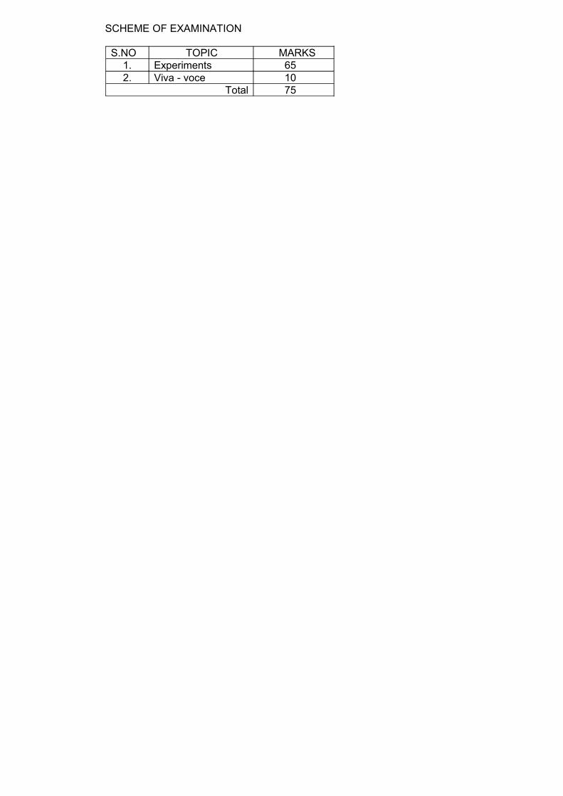
SCHEME OF EXAMINATION
S.NO TOPIC MARKS1. Exercise 652. Viva - voce 10
Total 75
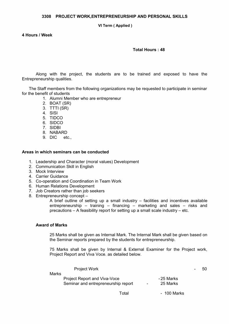
3308 PROJECT WORK,ENTREPRENEURSHIP AND PERSONAL SKILLS
VI Term ( Applied )
4 Hours / Week
Total Hours : 48
Along with the project, the students are to be trained and exposed to have the Entrepreneurship qualities.
The Staff members from the following organizations may be requested to participate in seminar for the benefit of students
1. Alumni Member who are entrepreneur2. BOAT (SR)3. TTTI (SR)4. SISI5. TIDCO6. SIDCO7. SIDBI8. NABARD9. DIC etc.,
Areas in which seminars can be conducted
1. Leadership and Character (moral values) Development2. Communication Skill in English3. Mock Interview4. Carrier Guidance 5. Co-operation and Coordination in Team Work6. Human Relations Development7. Job Creators rather than job seekers 8. Entrepreneurship concept –
A brief outline of setting up a small industry – facilities and incentives available entrepreneurship – training – financing – marketing and sales – risks and precautions – A feasibility report for setting up a small scale industry – etc.
Award of Marks
25 Marks shall be given as Internal Mark. The Internal Mark shall be given based on the Seminar reports prepared by the students for entrepreneurship.
75 Marks shall be given by Internal & External Examiner for the Project work, Project Report and Viva Voce. as detailed below.
Project Work - 50 Marks
Project Report and Viva-Voce - 25 MarksSeminar and entrepreneurship report - 25 Marks
Total - 100 Marks
Reference Books
Sl.No. Name of the Book Author Publisher
1
2
3
4
Electronics Projects for Beginners
Electronics Projects
Projects in Electrical and Electronics Engineering