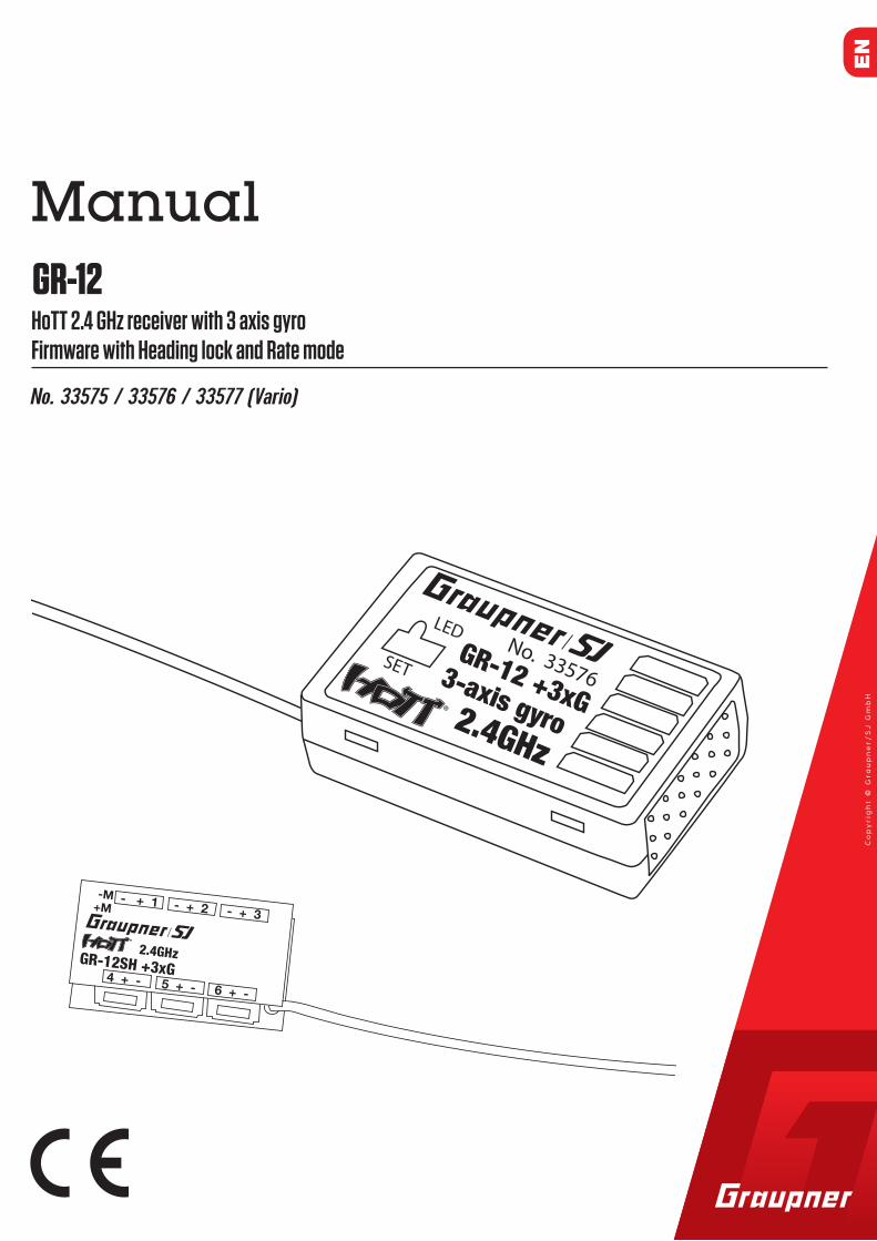
IntroductionThank you very much for purchasing the Graupner Receiver GR-12 HoTT 2.4 GHz 3 axis gyro. This receiver is extremely versatile.
Read this manual carefully to achieve the best results with your receiver and first of all to safely control your models. If you expe-rience any trouble during operation, take the instructions to help or ask your dealer or Graupner Service Centre.
Due to technical changes, the information may be changed in this manual without prior notice. Keep updated by regularly checking our own website, www.graupner.de to be always updated with the products and firmware.
This product complies with national and European legal require-ments.
To maintain this condition and to ensure safe operation, you must read and follow this user manual and the safety notes before using the product!
Note This manual is part of that product. It contains important information concerning operation and handling. Keep these instructions for future reference and give it to third person in case you gave the product.
Service CentreGraupner Central Service
Graupner/SJ GmbH
Henriettenstraße 96
D-73230 Kirchheim / Teck
Servicehotline
(+49) (0)7021/722-130
Monday - Thursday
9:15 am - 4:00 pm
Friday
9:15 am - 1:00 pm
Graupner USA3941 Park Dr Suite 20-571El Dorado Hills, CA 95762
Graupner in Internet For the service centers outside Germany please refer to our web site www.graupner.de
�
5 / 2433576_jp_V1
Intended useThe receiver is only suitable to be installed on airplanes models. More punctual information about receiver can be found in the Technical data section.
The receiver is designed exclusively to be used in battery-pow-ered, radio controlled models, any other use is not allowed. For any improper use no warranty or liability is accepted.
Read through this entire manual before you attempt to install or use the receiver.
Graupner/SJ constantly works on the development of all prod-ucts; we reserve the right to change the item, its technology and equipment.
Target groupThe product is not a toy. It is not suitable for children under 14 years. The installation and operation of the receiver must be per-formed by experienced modellers. If you do not have sufficient knowledge about dealing with radio-controlled models, please contact an experienced modeller or a model club.
Temperature range - 15...+70 °C -15 ... +70 °C -15 ... +70 °C
Antenna length 1x wire 30 mm 1 x wire 145 (Antenna
30) mm1 x wire 145 (Antenna
30) mmTotal weight approx.: 2,5 g approx.: 7 g approx.: 7 gFrequency 2400 ... 2483.5 MHz 2400 ... 2483.5 MHz 2400 ... 2483.5 MHzRange approx. 800 m 2000 m 2000 mDimensions approx. 23.5 x 15 x 6 mm 36 x 21 x 10 mm 36 x 21 x 10 mm
Modulation 2.4 GHz FHSS 2.4 GHz FHSS 2.4 GHz FHSSPower con-sumption 20 mA 70 mA 70 mA
Operating voltage (2.5) 3.6 ... 8,4 V (2.5) 3.6 ... 8,4 V (2.5) 3.6 ... 8,4 V
6 / 24
Symbols explication
! Always observe the information indicated by this warning sign.
Particularly those which are additionally marked with the CAU-TION or WARNING. The signal word WARNING indicates the poten-tial for serious injury, the signal word CAUTION indicates possibil-ity of lighter injuries.
The signal word Note indicates potential malfunctions.Attention indicates potential damages to objects.
Safety notes
! These safety instructions are intended not only to protect the
product, but also for your own and other people’s safety. There-fore please read this section very carefully before using the prod-uct!Do not carelessly leave the packaging material lying around, since it might become a dangerous toy for children.
� Persons, including children, with reduced physical, sensory or mental capabilities, or lack of experience or knowledge, or not capable to use safely the receiver must not use the receiver without supervision or instruction by a responsible person.
� Operation and use of radio-controlled models needs to be learned! If you have never operated a model of this type before, start carefully and make yourself familiar with the model's reactions to the remote control commands. Pro-ceed responsibly.
� First, always perform a range and function test on the ground (to do so, hold your model tight), before you use your model. Repeat the test with running motor and with short throttle bursts.
� Before you start using the remote control model, you have to check the further relevant laws and regulations. These laws you must obey in every case. Pay attention to the pos-sibly different laws of the countries.
33576_jp_V1
7 / 2433576_jp_V1
� The insurance is mandatory for all kinds of model operation. If you already have one, please inform yourself if the opera-tion of the respective model is covered by your insurance. If this is not the case, conclude a special liability insurance pol-icy for models. We recommend to provide your model with a label, where your personal data are indicated. So that the model can be clearly assigned in the event of a crash.
� Due to safety and licensing reasons (CE), any reconstruction and/or modification of the product is prohibited.
� Only use the components and spare parts that we recom-mend. Always use matching, original Graupner plug-in con-nections of the same design and material.
� Make sure that all of the plug-in connections are tight. When disconnecting the plug-in connections, do not pull the cables.
� Protect the receiver from dust, dirt, moisture and foreign parts. It must be protected from vibration as well as exces-sive heat or cold. The models may only be operated remotely in normal outside temperatures such as from -10°C to +55°C.
� Only operate all your components using the current software version.
� If you have questions which cannot be answered by the operating manual, please contact us or another expert in the field.
WARNING � Also while programming, make sure that a connected elec-
tric motor cannot accidentally start. Risk of injury by rotating propellers!
� Avoid shock and pressure. Check the receiver regularly for damages to the housings and cables, specially after model crashes. Damaged or wet receiver, even if re-dried, should no longer be used!
!
8 / 24 33576_jp_V1
InstallationThe receiver must be aligned at right angles to the model on the receiver platform.
The lower surface of the receiver must always be parallel to one of the model sides.
Prior to installation, remove the sticker on the back of the receiver. We recommend using double-sided tape No.: S8376 for Gr-18 to fix the receiver in place.
BindingBinding is only possible if the receiver has not been linked with a bound transmitter since being switched on (red LED lights). Press the SET button to set the receiver to BIND mode.
If you wish to bind the receiver to a new model memory, this is the procedure:
� Switch the transmitter’s RF section off in the “Basic model settings” menu (see transmitter manual)
� Switch on the receiver and put it in binding mode, by press-ing and holding the binding button (green and red LED on the receiver are flashing)
� Initiate binding in the transmitter’s “Basic model settings” menu.
� If the red LED of the receiver goes out within about 10 sec-onds, the binding process has been completed successfully.
� Your transmitter/receiver combination is now ready for oper-ation.
� If the red LED is still lit, the "binding“ failed. In this case, repeat the whole procedure.
9 / 2433576_jp_V1
ConnectionsConnect the servos to the row of sockets on one end of the receiver. The connectors are reverse polarity protected: note the small chamfers on the sides. Never use force – the connectors should engage easily. The polarity is also printed on the receiver; the negative wire (-) is brown, the positive (+) red and the signal orange. The servo sockets of Graupner/SJ HoTT 2.4 receivers are numbered sequentially.
The socket for channel 6 can also be programmed to deliver a (digital) sum signal (see receiver settings section).
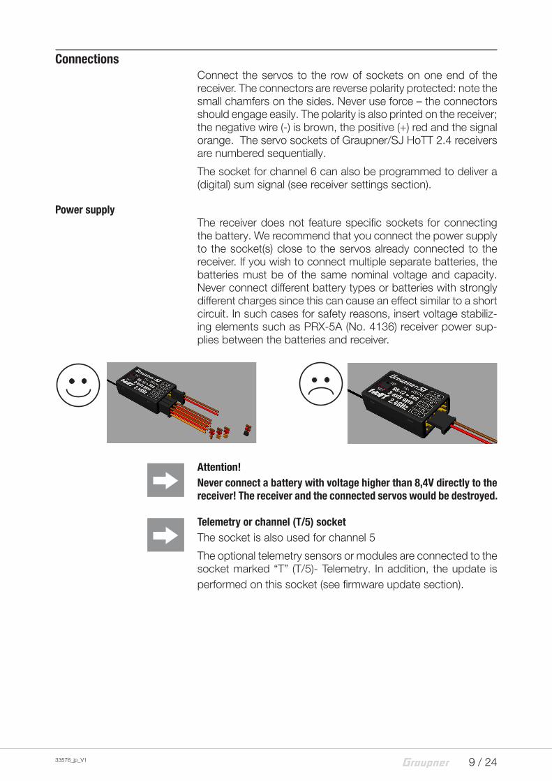
Power supplyThe receiver does not feature specific sockets for connecting the battery. We recommend that you connect the power supply to the socket(s) close to the servos already connected to the receiver. If you wish to connect multiple separate batteries, the batteries must be of the same nominal voltage and capacity. Never connect different battery types or batteries with strongly different charges since this can cause an effect similar to a short circuit. In such cases for safety reasons, insert voltage stabiliz-ing elements such as PRX-5A (No. 4136) receiver power sup-plies between the batteries and receiver.
Attention!Never connect a battery with voltage higher than 8,4V directly to the receiver! The receiver and the connected servos would be destroyed.
Telemetry or channel (T/5) socketThe socket is also used for channel 5
The optional telemetry sensors or modules are connected to the socket marked “T” (T/5)- Telemetry. In addition, the update is performed on this socket (see firmware update section).
10 / 24 33576_jp_V1
Programming the receiver settingsThe receiver can be programmed with a suitable HoTT transmit-ter or in connection with the SMART-BOX.
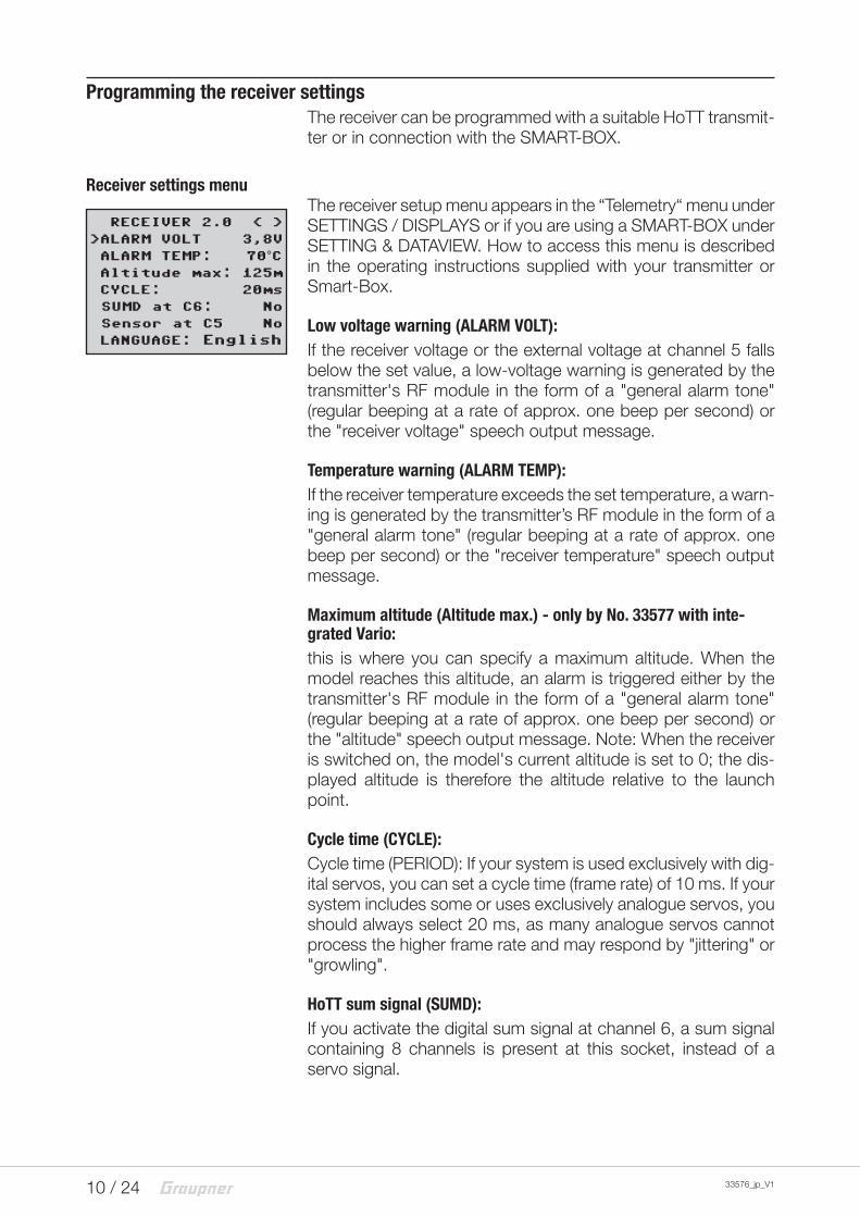
Receiver settings menuThe receiver setup menu appears in the “Telemetry“ menu under SETTINGS / DISPLAYS or if you are using a SMART-BOX under SETTING & DATAVIEW. How to access this menu is described in the operating instructions supplied with your transmitter or Smart-Box.
Low voltage warning (ALARM VOLT):If the receiver voltage or the external voltage at channel 5 falls below the set value, a low-voltage warning is generated by the transmitter's RF module in the form of a "general alarm tone" (regular beeping at a rate of approx. one beep per second) or the "receiver voltage" speech output message.
Temperature warning (ALARM TEMP):If the receiver temperature exceeds the set temperature, a warn-ing is generated by the transmitter’s RF module in the form of a "general alarm tone" (regular beeping at a rate of approx. one beep per second) or the "receiver temperature" speech output message.
Maximum altitude (Altitude max.) - only by No. 33577 with inte-grated Vario:this is where you can specify a maximum altitude. When the model reaches this altitude, an alarm is triggered either by the transmitter's RF module in the form of a "general alarm tone" (regular beeping at a rate of approx. one beep per second) or the "altitude" speech output message. Note: When the receiver is switched on, the model's current altitude is set to 0; the dis-played altitude is therefore the altitude relative to the launch point.
Cycle time (CYCLE):Cycle time (PERIOD): If your system is used exclusively with dig-ital servos, you can set a cycle time (frame rate) of 10 ms. If your system includes some or uses exclusively analogue servos, you should always select 20 ms, as many analogue servos cannot process the higher frame rate and may respond by "jittering" or "growling".
HoTT sum signal (SUMD):If you activate the digital sum signal at channel 6, a sum signal containing 8 channels is present at this socket, instead of a servo signal.
RECEIVER 2.0 < >
>ALARM VOLT 3,8V
ALARM TEMP: 70°C Altitude max: 125m
>CYCLE: 20ms
SUMD at C6: No
Sensor at C5 No
LANGUAGE: English
11 / 2433576_jp_V1
The HoTT receiver configured as SUMD constantly generates a digital sum signal from 8 control signals from the transmitter and makes this signal available at the specified servo socket, which is receiver-specific. At the time this manual was revised, this type of signal was being used by several of the latest electronic applications of flybarless systems, power supplies, etc.
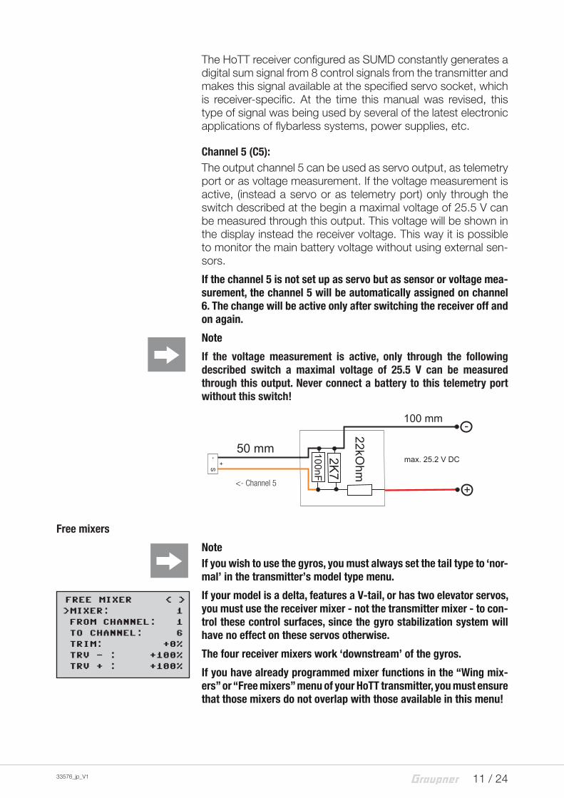
Channel 5 (C5):The output channel 5 can be used as servo output, as telemetry port or as voltage measurement. If the voltage measurement is active, (instead a servo or as telemetry port) only through the switch described at the begin a maximal voltage of 25.5 V can be measured through this output. This voltage will be shown in the display instead the receiver voltage. This way it is possible to monitor the main battery voltage without using external sen-sors.
If the channel 5 is not set up as servo but as sensor or voltage mea-surement, the channel 5 will be automatically assigned on channel 6. The change will be active only after switching the receiver off and on again.
Note
If the voltage measurement is active, only through the following described switch a maximal voltage of 25.5 V can be measured through this output. Never connect a battery to this telemetry port without this switch!
Free mixers
NoteIf you wish to use the gyros, you must always set the tail type to ‘nor-mal’ in the transmitter’s model type menu.
If your model is a delta, features a V-tail, or has two elevator servos, you must use the receiver mixer - not the transmitter mixer - to con-trol these control surfaces, since the gyro stabilization system will have no effect on these servos otherwise.
The four receiver mixers work ‘downstream’ of the gyros.
If you have already programmed mixer functions in the “Wing mix-ers” or “Free mixers” menu of your HoTT transmitter, you must ensure that those mixers do not overlap with those available in this menu!
<- Channel 5
FREE MIXER < >>MIXER: 1
FROM CHANNEL: 1
>TO CHANNEL: 6
>TRIM: +0%
TRV - : +100%
TRV + : +100%
12 / 24 33576_jp_V1
MIXER:Up to four mixers can be contemporaneously programmed . You can switch between Mixer 1, Mixer 2, … and mixer 4 in the “Mixer” line.
The following settings only affect the mixer selected in this line.
FROM CHANNEL:The signal source (or source channel) is mixed in to the target channel (TO CHANNEL) with a programmable amount. The method of setting up the values is analogous to the “Free mix-ers” menu in HoTT transmitters.
TO CHANNEL:
Part of the source channel signal (FROM CHANNEL) is mixed into the target channel (TO CHANNEL). The mixer ratio is deter-mined by the percentage values entered in the “TRAVEL-” and “TRAVEL+” lines. Select “0” if you do not require the mixer.
Mixer ratio (TRAVEL-/+): in these two lines you can define the mixer ratio in relation to the source channel (FROM CHANNEL); the value is set separately for both directions.
Programming examples
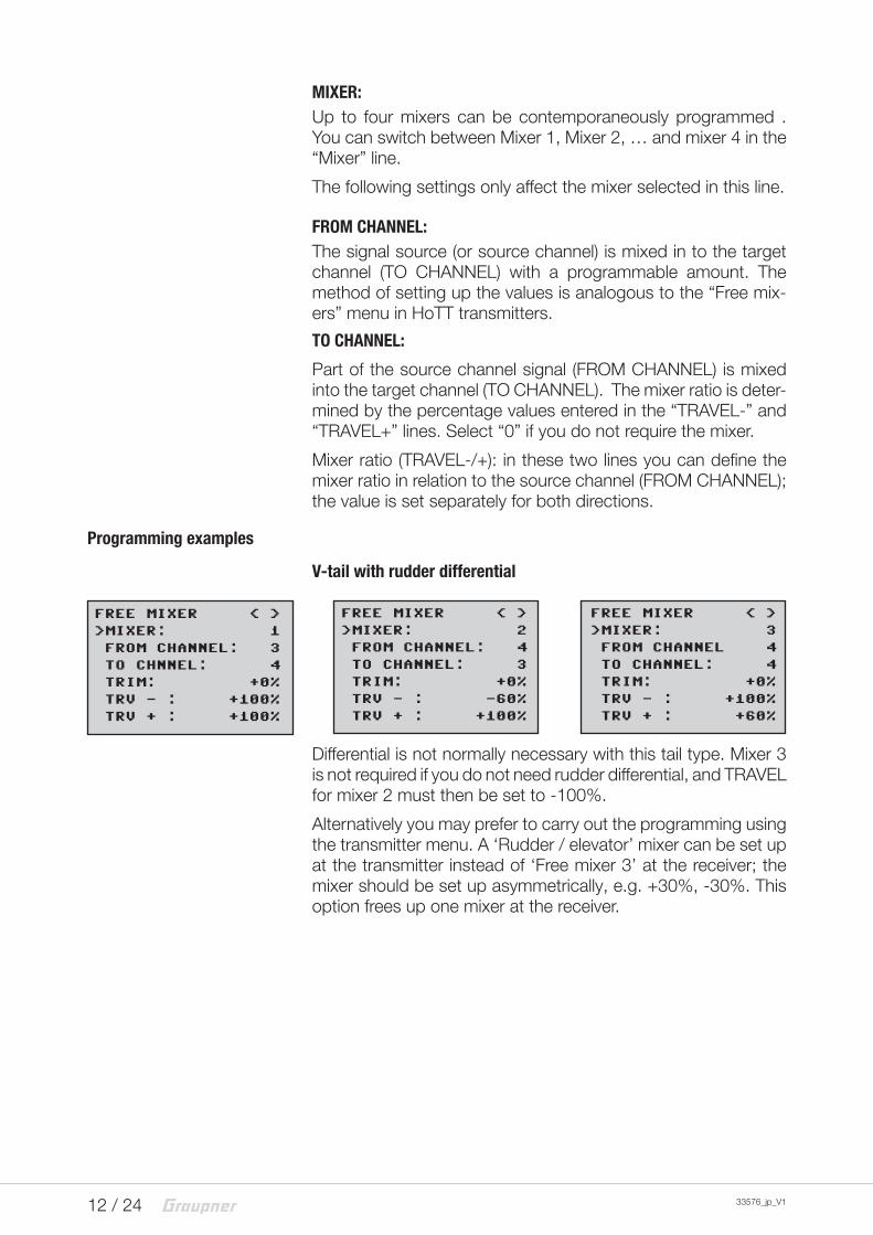
V-tail with rudder differential
Differential is not normally necessary with this tail type. Mixer 3 is not required if you do not need rudder differential, and TRAVEL for mixer 2 must then be set to -100%.
Alternatively you may prefer to carry out the programming using the transmitter menu. A ‘Rudder / elevator’ mixer can be set up at the transmitter instead of ‘Free mixer 3’ at the receiver; the mixer should be set up asymmetrically, e.g. +30%, -30%. This option frees up one mixer at the receiver.
FREE MIXER < >
>MIXER: 2
FROM CHANNEL: 4
>TO CHANNEL: 3
>TRIM: +0%
TRV - : -60%
TRV + : +100%
FREE MIXER < >
>MIXER: 3
FROM CHANNEL 4
>TO CHANNEL: 4
>TRIM: +0%
TRV - : +100%
TRV + : +60%
FREE MIXER < >
>MIXER: 1
FROM CHANNEL: 3
>TO CHNNEL: 4
>TRIM: +0%
TRV - : +100%
TRV + : +100%
13 / 2433576_jp_V1
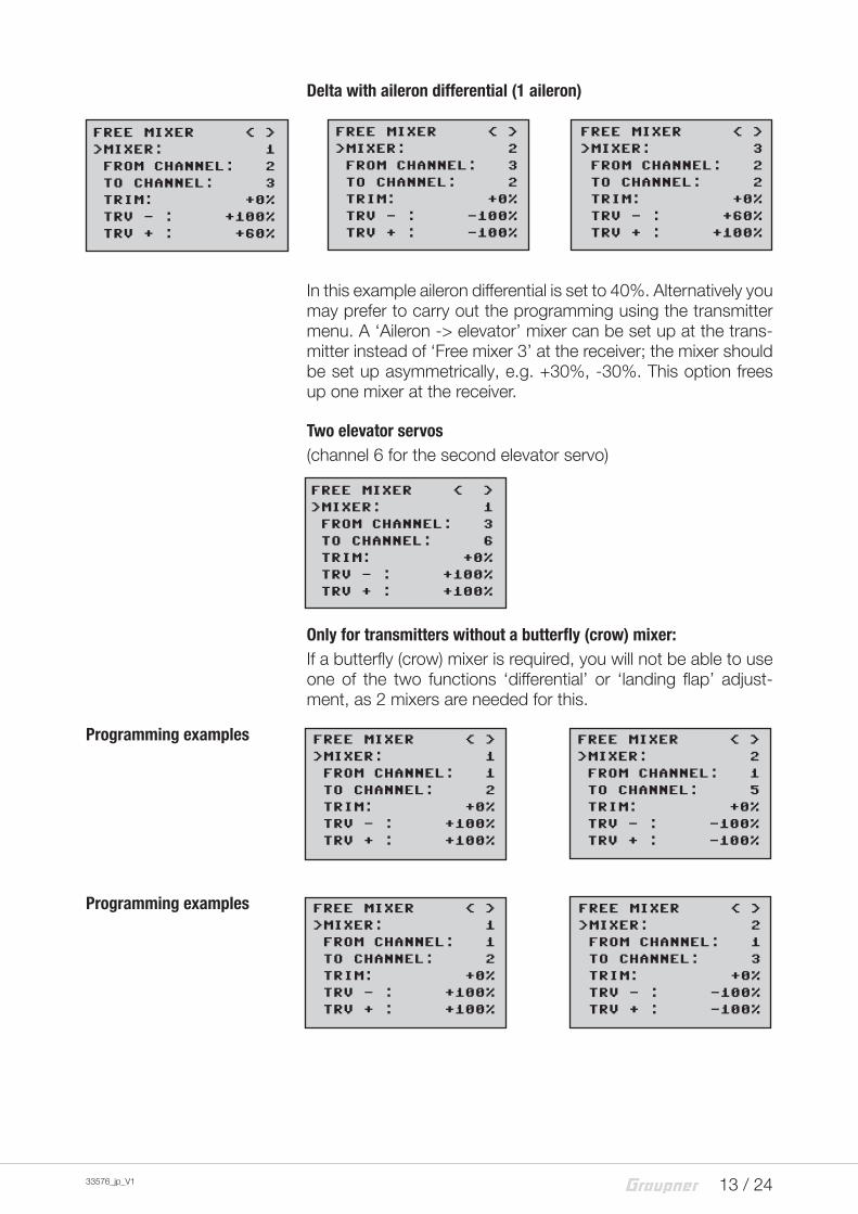
Delta with aileron differential (1 aileron)
In this example aileron differential is set to 40%. Alternatively you may prefer to carry out the programming using the transmitter menu. A ‘Aileron -> elevator’ mixer can be set up at the trans-mitter instead of ‘Free mixer 3’ at the receiver; the mixer should be set up asymmetrically, e.g. +30%, -30%. This option frees up one mixer at the receiver.
Two elevator servos(channel 6 for the second elevator servo)
Only for transmitters without a butterfly (crow) mixer:If a butterfly (crow) mixer is required, you will not be able to use one of the two functions ‘differential’ or ‘landing flap’ adjust-ment, as 2 mixers are needed for this.
Programming examples
Programming examples
FREE MIXER < >
>MIXER: 2
FROM CHANNEL: 3
>TO CHANNEL: 2
>TRIM: +0%
TRV - : -100%
TRV + : -100%
FREE MIXER < >
>MIXER: 3
FROM CHANNEL: 2
>TO CHANNEL: 2
>TRIM: +0%
TRV - : +60%
TRV + : +100%
FREE MIXER < >
>MIXER: 1
FROM CHANNEL: 2
>TO CHANNEL: 3
>TRIM: +0%
TRV - : +100%
TRV + : +60%
FREE MIXER < >
>MIXER: 1
FROM CHANNEL: 3
>TO CHANNEL: 6
>TRIM: +0%
TRV - : +100%
TRV + : +100%
FREE MIXER < >
>MIXER: 1
FROM CHANNEL: 1
>TO CHANNEL: 2
>TRIM: +0%
TRV - : +100%
TRV + : +100%
FREE MIXER < >
>MIXER: 2
FROM CHANNEL: 1
>TO CHANNEL: 5
>TRIM: +0%
TRV - : -100%
TRV + : -100%
FREE MIXER < >
>MIXER: 1
FROM CHANNEL: 1
>TO CHANNEL: 2
>TRIM: +0%
TRV - : +100%
TRV + : +100%
FREE MIXER < >
>MIXER: 2
FROM CHANNEL: 1
>TO CHANNEL: 3
>TRIM: +0%
TRV - : -100%
TRV + : -100%
14 / 24 33576_jp_V1
Gyro assignment
>AILERON SERVOS:Aileron servos: you should enter the value 2 in this line if your model has two aileron servos. In this case the gyro for channel (servo) 2 also acts on servo 5. If the ailerons are also used as flaperons or speedbrakes, gyro suppression is based on the sum of both channels.
NoteThe servo reverse setting must be the same for both aileron servos, i.e. either both ‘normal’ or both ‘reverse’. If this is not possible, on no account should you reverse one servo in the transmitter menu. The only option is to re-install it in the model by turning it round physi-cally.
However, if your model is fitted with programmable servos (e.g. Graupner DES, HVS or HBS types - see the instructions for the update program ‘Firmware_Upgrade_grStudio - then it is possible to reverse the direction of rotation at the servo itself.
Please read the installation notes on page 8 of these instruc-tions. The first step is to define the three gyro axes and the ori-entation of the receiver. This is accomplished by switching on the transmitter and model, and selecting ‘New setting: yes’ in the receiver’s ‘Gyro settings’ menu.
� Now move the stick for any control surface to full travel (in the servo display at least 25%) in the indicated direction; in the following example we use the aileron channel.
� The detected axis (aileron) is highlighted (black background). (In the receiver’s default state the value for all axes is shown as ‘+0’; the axes can also be set manually to ‘+0’. 0 = inac-tive)
� Now turn the model through at least 45° in the direction cor-responding to the stick movement. For example, if you moved the aileron stick to the left, you must simulate a left turn with the model -> move the left wing down through at least 45°.
� This process defines the one axis and direction; now you must repeat the procedure for the other two axes.
Axis assignment < >
>AILERON SERVOS: 2
New setup: Yes
AILE: (right) +2
ELEV:(push) +0
RUDD:(right) +0
Axis assignment < >
>AILERON SERVOS: 2
New setup: No
AILE: (right) +2
ELEV:(push) +1
RUDD:(right) -3
15 / 2433576_jp_V1
� The gyro axis 1, 2 or 3 is now displayed in the ‘Aileron / Ele-vator / Rudder’ display; a negative prefix will appear if servo reverse is activated.
� Once all three axes are defined, the display automatically reverts to ‘New setting: no’.
Elevator:
Movement of the model Control surface action (tail view)
Rudder:
Movement of the model Control surface action (tail view)
Aileron:
Movement of the model Control surface action (tail view)
! CAUTION
Check that all the gyros are working in the correct direc-tion!
Move the model in all axes directions. Check the move-ments and travels.
Now check the control surface deflections - see diagrams below.
You must not fly the model before doing this: crash hazard!
16 / 24 33576_jp_V1
NoteBefore you start entering settings for a new model, it is essential to select the number of aileron servos in the Aileron servos menu point, and to define the gyro axes and orientation in the New settings menu point.
Programming the regulation
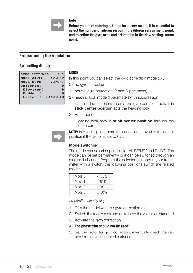
Gyro setting display
MODEIn this point you can select the gyro correction mode (0-3):
0 - no gyro correction
1 - normal gyro correction (P and D parameter)
2 - heading lock mode (I parameter) with suppression
(Outside the suppression area the gyro control is active, in stick center position acts the heading lock)
3 - Rate mode
(Heading lock acts in stick center position through the entire area)
NOTE: In Heading lock mode the servos are moved to the center position if the factor is set to 0%.
Mode switchingThe mode can be set separately for AILE/ELEV and RUDD. The mode can be set permanently or it can be switched through an assigned channel. Program the selected channel in your trans-mitter with a switch, the following positions switch the related mode:
Mode 0 - 100%Mode 1 - 50%Mode 2 0%Mode 3 ≥ 50%
Preparation step by step:
1. Trim the model with the gyro correction off
2. Switch the receiver off and on to save the values as standard
3. Activate the gyro correction
4. The phase trim should not be used!
5. Set the factor for gyro correction, eventually check the val-ues for the single control surfaces
GYRO SETTINGS < >
MODE AI/EL (2)CH7
MODE RUDD (2)CH7
>Aileron: 0
>Elevator: 0
Rudder : 0
Factor : (44%)C10
17 / 2433576_jp_V1
Note
If the model is too agile in mode 3, it is then recommended to set in the transmitter DUAL RATE and/or EXPO for this mode. Thus the model will react in a more docile way. In the Rate mode the model tries to reach the controlled rate. Also in mode 2 EXPO can be useful.
Aileron/elevator/rudder:Shows the programmable factors for the corresponding control surface.
The gyro correction can also be disabled by setting the value to OFF. Do not exceed 4 - 5 as maximum value for the normal flight phase, 2 - 3 for speed, 3 - 6 for landing. The maximum value of 10 should be reserved for torque-rolls only.
Factor (general sensitivity)
Setting this value the 3 parameters will be influenced contem-poraneously.
General sensitivity for all gyros, action grade settable through a controller between 0 and 200%
Move the cursor to the Factor line. Move the cursor to reorder the factor for aileron, elevator and rudder by using a proportional control (adjustment range up to 200%; channel value -100% means a factor of 0%, channel value 0% means 100%, and +100% means 200%). This makes it a very easy matter to match the gyro’s corrective effect to the model’s airspeed. In particular, higher gyro gain can be used for the landing approach - without the need to switch flight phases.Once you have found the optimum settings, you can set up a transmitter switch to control the gyro, i.e. for switching between gain settings. For example, you could assign a 3 position switch to “Factor”, and then use it to switch the values between 0% and 100% (OFF) so as 200%. In the transmitter the servo dis-play for this 3 functions switch must indicate -100, 0 and +100%.
Note
The OFF value means a gyro action of 100%!
Good to know!
The standard factor should cause the gyros to correct the mod-el’s attitude quickly when it is upset by an outside influence. Without causing oscillation, but in practice the optimum values for a particular model can only be found by flight-testing. If the model shows little or no automatic stabilization with the default settings, the value should be raised; on the other hand. If the model oscillates (wave-like movements in flight), the value should be reduced.
18 / 24 33576_jp_V1
Some transmitters allow the corrective factors to be altered during a flight using the proportional controls, whereas others allow fixed values only.
Flight phase specific settingsIt is possible to use a channel to control the factor value by set-ting up flight phase specific transmitter control settings, but only with mx-20 / mc-20 / mc-32 / MZ-24PRO; please see the instructions supplied with your transmitter and refer to the “Transmitter control settings” and “Flight phase settings”.
Programming the axes sensitivity
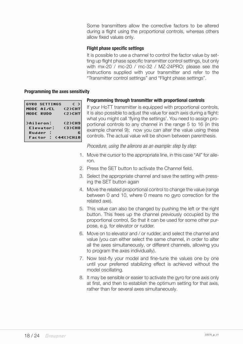
Programming through transmitter with proportional controlsIf your HoTT transmitter is equipped with proportional controls, it is also possible to adjust the value for each axis during a flight: what you might call ‘flying the settings’. You need to assign pro-portional controls to any channel in the range 5 to 16 (in this example channel 9); now you can alter the value using these controls. The actual value will be shown between parenthesis.
Procedure, using the ailerons as an example: step by step:
1. Move the cursor to the appropriate line, in this case “Ail” for aile-ron.
2. Press the SET button to activate the Channel field.
3. Select the appropriate channel and save the setting with press-ing the SET button again
4. Move the related proportional control to change the value (range between 0 and 10, where 0 means no gyro correction for the related axe).
5. This value can also be changed by pushing the left or the right button. This frees up the channel previously occupied by the proportional control, So that it can be used for some other pur-pose, e.g. for elevator or rudder.
6. Move on to elevator and / or rudder, and select the channel and value (you can either select the same channel, in order to alter all the axes simultaneously, or different channels, allowing you to program the axes individually).
7. Now test-fly your model and fine-tune the values one by one until your preferred stabilizing effect is achieved without the model oscillating.
8. It may be sensible or easier to activate the gyro for one axis only at first, and then to establish the optimum setting for that axis, rather than for several axes simultaneously.
GYRO SETTINGS < >
MODE AI/EL (2)CH7
MODE RUDD (2)CH7
>Aileron: (2)CH9
>Elevator: (3)CH8
Rudder : 6
Factor : (44%)CH10
19 / 2433576_jp_V1
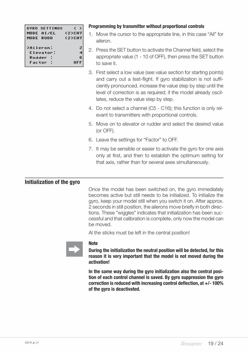
Programming by transmitter without proportional controls
1. Move the cursor to the appropriate line, in this case “Ail” for aileron.
2. Press the SET button to activate the Channel field, select the appropriate value (1 - 10 of OFF), then press the SET button to save it.
3. First select a low value (see value section for starting points) and carry out a test-flight. If gyro stabilization is not suffi-ciently pronounced, increase the value step by step until the level of correction is as required; if the model already oscil-lates, reduce the value step by step.
4. Do not select a channel (C5 - C16); this function is only rel-evant to transmitters with proportional controls.
5. Move on to elevator or rudder and select the desired value (or OFF).
6. Leave the settings for “Factor” to OFF.
7. It may be sensible or easier to activate the gyro for one axis only at first, and then to establish the optimum setting for that axis, rather than for several axes simultaneously.
Initialization of the gyroOnce the model has been switched on, the gyro immediately becomes active but still needs to be initialized. To initialize the gyro, keep your model still when you switch it on. After approx. 2 seconds in still position, the ailerons move briefly in both direc-tions. These "wiggles" indicates that initialization has been suc-cessful and that calibration is complete, only now the model can be moved.
Al the sticks must be left in the central position!
NoteDuring the initialization the neutral position will be detected, for this reason it is very important that the model is not moved during the activation!
In the same way during the gyro initialization also the central posi-tion of each control channel is saved. By gyro suppression the gyro correction is reduced with increasing control deflection, at +/- 100% of the gyro is deactivated.
GYRO SETTINGS < >
MODE AI/EL (2)CH7
MODE RUDD (2)CH7
>Aileron: 2
>Elevator: 4
Rudder : 6
Factor : OFF
20 / 24 33576_jp_V1
Firmware updateUpdates to the receiver’s firmware are made via the output chan-nel 5 / telemetry socket using a PC running Windows XP, Vista or 7. You will also need a USB interface, order No. 7168.6, and adapter lead, order No. 7168.6A or 7168.S, which are available separately.
The programs and files required can be found in the Download area for the corresponding products at www.graupner.de.
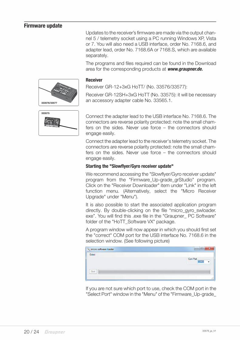
Receiver GR-12SH+3xG HoTT (No. 33575): it will be necessary an accessory adapter cable No. 33565.1.
Connect the adapter lead to the USB interface No. 7168.6. The connectors are reverse polarity protected: note the small cham-fers on the sides. Never use force – the connectors should engage easily.
Connect the adapter lead to the receiver's telemetry socket. The connectors are reverse polarity protected: note the small cham-fers on the sides. Never use force – the connectors should engage easily.
Starting the "Slowflyer/Gyro receiver update"
We recommend accessing the "Slowflyer/Gyro receiver update" program from the "Firmware_Up-grade_grStudio" program. Click on the "Receiver Downloader" item under "Link" in the left function menu. (Alternatively, select the "Micro Receiver Upgrade" under "Menu").
It is also possible to start the associated application program directly. By double-clicking on the file “micro_gyro_swloader.exe”. You will find this .exe file in the "Graupner_ PC Software" folder of the "HoTT_Software VX" package.
A program window will now appear in which you should first set the "correct" COM port for the USB interface No. 7168.6 in the selection window. (See following picture)
If you are not sure which port to use, check the COM port in the "Select Port" window in the "Menu" of the "Firmware_Up-grade_
333575
333576/33577
21 / 2433576_jp_V1
grStudio" and note down the COM port number for the "Silicon Labs CP210x USB to UART Bridge" entry – in this case "COM03". (If you select the wrong port, you will be alerted to this when you read out the receiver data). Click on "File" to load the corre-sponding firmware file named e.g. "GR12_33577_V_XX.bin" from the hard disc ("XX" stands for the version number).
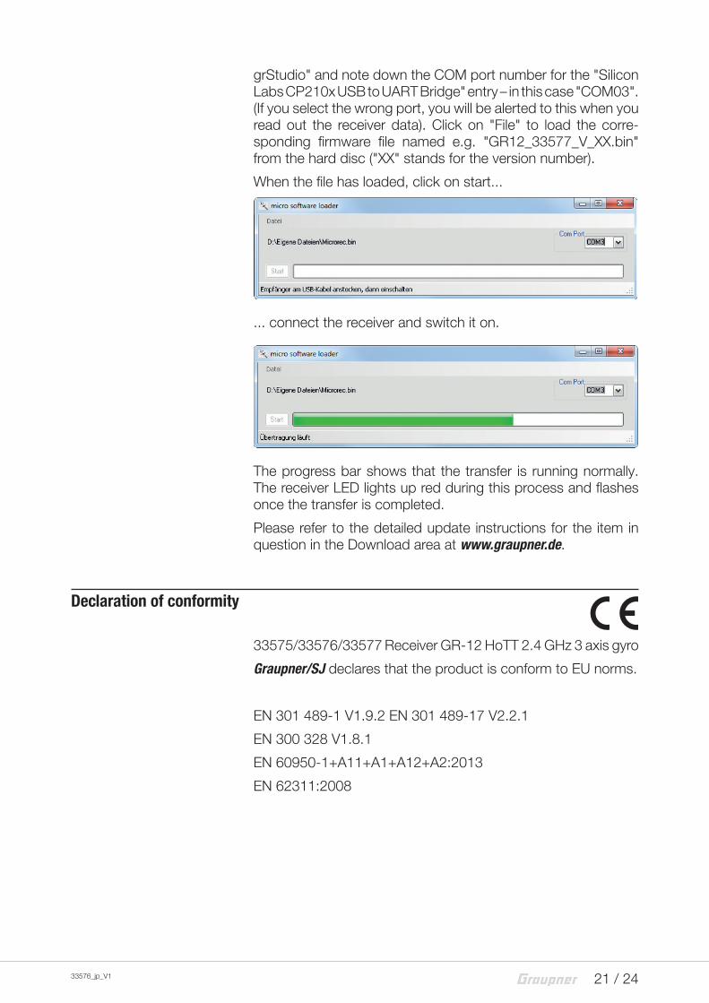
When the file has loaded, click on start...
... connect the receiver and switch it on.
The progress bar shows that the transfer is running normally. The receiver LED lights up red during this process and flashes once the transfer is completed.
Please refer to the detailed update instructions for the item in question in the Download area at www.graupner.de.
Graupner/SJ declares that the product is conform to EU norms.
EN 301 489-1 V1.9.2 EN 301 489-17 V2.2.1
EN 300 328 V1.8.1
EN 60950-1+A11+A1+A12+A2:2013
EN 62311:2008
22 / 24 33576_jp_V1
Notes on environmental protection
Disposal notesThis symbol on the product, user manual or packaging indicates that this product must not be disposed of with other household waste at the end of its life. It must be handed over to the appli-cable collection point for the recycling of electrical and electronic equipment.
The materials are recyclable as marked. By recycling, material reusing or other forms of scrap usage you are making an import-ant contribution to environmental protection.
Care and maintenance
Notes on careThe product does not need any maintenance, it works so as it is without any special care. In your own interests protect it from dust, dirt and moisture.
Clean the product only with a dry cloth (do not use detergent!) lightly rub.
WarrantyThe Graupner, Henriettenstrassee 96, 73230 Kirchheim/Teck grants from the date of purchase of this product for a period of 24 months. The warranty applies only to the material or opera-tional defects already existing when you purchased the item. Damage due to wear, overloading, incorrect accessories or improper handling are excluded from the guarantee. The legal rights and claims are not affected by this guarantee. Please check exactly defects before a claim or send the product, because we have to ask you to pay shipping costs if the item is free from defects.
The present construction or user manual is for informational pur-poses only and may be changed without prior notice. The cur-rent version can be found on the Internet at www.graupner.de on the relevant product page. In addition, the company Graupner has no responsibility or liability for any errors or inaccuracies that may appear in construction or operation manuals.