RELEASE - R3.0 SECTION 34 11 31 BART FACILITIES STANDARDS Issued: January 2013 PAGE 1 OF 29 STANDARD SPECIFICATIONS SECTION 34 11 31 CONCRETE TIES PART I – GENERAL 1.01 SECTION INCLUDES A. Crossties (CT) B. Concrete Special Trackwork Ties (SPCT). 1.02 RELATED SECTIONS A. Refer to Section 34 05 17 - Common Work Results for Trackway, for related requirements. B. Refer to Section 34 11 37 - Direct Fixation Fasteners, for additional testing requirements. 1.03 MEASUREMENT AND PAYMENT A. General: Concrete ties will not be measured separately for payment. All costs in connection therewith will be considered as included in the applicable Contract lump sum price or the Contract unit price per linear foot for trackwork of the different types indicated as listed in the bid item in the Bid Schedule of the Bid Form. 1.04 REFERENCES A. American Association of State Highway and Transportation Officials (AASHTO): 1. AASHTO T277 Permeability of HPC: Rapid Choride Ion Test vs. Chloride Ponding Test. B. American Concrete Institute (ACI): 1. ACI 305R Hot Weather Concreting 2. ACI 318/318R Chapter 18, Prestressed Concrete, Section 18.4, Permissible Stresses in Concrete Flexural Members. C. American Railway Engineering and Maintenance of Way Association (AREMA): 1. AREMA Manual. D. American Society for Testing and Materials (ASTM): 1. ASTM A416/416M Standard Specification for Steel Strand, Uncoated Seven-Wire for Prestressed Concrete. 2. ASTM A881/A881M Standard Specification for Steel Wire, Deformed, Stress- Relieved or Low-Relaxation for Prestressed Concrete Railroad Ties. 3. ASTM A886/A886M Standard Specification for Steel Strand, Indented, Seven-Wire Stress-Relieved for Prestressed Concrete.
Transcript
RELEASE - R3.0 SECTION 34 11 31 BART FACILITIES STANDARDS Issued: January 2013 PAGE 1 OF 29 STANDARD SPECIFICATIONS
SECTION 34 11 31
CONCRETE TIES
PART I – GENERAL
1.01 SECTION INCLUDES
A. Crossties (CT)
B. Concrete Special Trackwork Ties (SPCT).
1.02 RELATED SECTIONS
A. Refer to Section 34 05 17 - Common Work Results for Trackway, for related requirements.
B. Refer to Section 34 11 37 - Direct Fixation Fasteners, for additional testing requirements.
1.03 MEASUREMENT AND PAYMENT
A. General: Concrete ties will not be measured separately for payment. All costs in connection therewith will be considered as included in the applicable Contract lump sum price or the Contract unit price per linear foot for trackwork of the different types indicated as listed in the bid item in the Bid Schedule of the Bid Form.
1.04 REFERENCES
A. American Association of State Highway and Transportation Officials (AASHTO):
1. AASHTO T277 Permeability of HPC: Rapid Choride Ion Test vs. Chloride Ponding Test.
C. American Railway Engineering and Maintenance of Way Association (AREMA):
1. AREMA Manual.
D. American Society for Testing and Materials (ASTM):
1. ASTM A416/416M Standard Specification for Steel Strand, Uncoated Seven-Wire for Prestressed Concrete.
2. ASTM A881/A881M Standard Specification for Steel Wire, Deformed, Stress-Relieved or Low-Relaxation for Prestressed Concrete Railroad Ties.
3. ASTM A886/A886M Standard Specification for Steel Strand, Indented, Seven-Wire Stress-Relieved for Prestressed Concrete.
CONCRETE TIES
RELEASE - R3.0 SECTION 34 11 31 BART FACILITIES STANDARDS Issued: January 2013 PAGE 2 OF 29 STANDARD SPECIFICATIONS
4. ASTM C31/C31M Standard Practice for Making and Curing Concrete Test Specimens in the Field.
5. ASTM C33 Standard Specification for Concrete Aggregates.
6. ASTM C39/C39M Standard Test Method for Compressive Strength of Cylindrical Concrete Specimens.
7. ASTM C78 Standard Test Method for Flexural Strength of Concrete (Using Simple Beam with Third-Point Loading).
8. ASTM C94/C94M Standard Specification for Ready-Mixed Concrete.
9. ASTM C114 Standard Test Methods for Chemical Analysis of Hydraulic Cement.
10. ASTM C150 Standard Specification for Portland Cement.
11. ASTM C157/C157M Standard Test Method for Length Change of Hardened Hydraulic-Cement, Mortar, and Concrete.
12. ASTM C172 Standard Practice for Sampling Freshly Mixed Concrete.
13. ASTM C227 Standard Test Method for Potential Alkali Reactivity of Cement-Aggregate Combinations (Mortar-Bar Method).
14. ASTM C289 Standard Test Method for Potential Alkali-Silica Reactivity of Aggregates (Chemical Method).
15. ASTM C295 Standard Guide for Petrographic Examination of Aggregates for Concrete.
16. ASTM C359 Standard Test Method for Early Stiffening of Hydraulic Cement (Mortar Method).
17. ASTM C490 Standard Practice for Use of Apparatus for the Determination of Length Change of Hardened Cement Paste, Mortar, and Concrete.
18. ASTM C494/C494M Standard Specification for Chemical Admixtures for Concrete.
19. ASTM C586 Standard Test Method for Potential Alkali Reactivity of Carbonate Rocks for Concrete Aggregates (Rock Cylinder Method).
20. ASTM C617 Standard Practice for Capping Cylindrical Concrete Specimens.
21. ASTM C917 Standard Test Method for Evaluation of Cement Strength Uniformity From a Single Source.
22. ASTM C1017/C1017M Standard Specification for Chemical Admixtures for Use in Producing Flowing Concrete.
CONCRETE TIES
RELEASE - R3.0 SECTION 34 11 31 BART FACILITIES STANDARDS Issued: January 2013 PAGE 3 OF 29 STANDARD SPECIFICATIONS
23. ASTM C1105 Standard Test Method for Length Change of Concrete Due to Alkali-Carbonate Rock Reaction.
24. ASTM C1260 Standard Test Method for Potential Alkali Reactivity of Aggregates (Mortar-Bar Method).
25. ASTM D512 Standard Test Methods for Chloride Ion In Water.
26. ASTM D1411 Standard Test Methods for Water-Soluble Chlorides Present as Admixtures in Graded Aggregate Road Mixes.
E. Precast/Prestressed Concrete Institute (PCI):
1. PCI MNL 116 Manual for Quality Control for Plants and Production of Structural Precast Concrete Products.
1.05 SUBMITTALS
A. Refer to Section 01 33 00 - Submittal Procedures, and Section 01 33 23 - Shop Drawings, Product Data, and Samples, for submittal requirements and procedures.
B. Refer to Section 34 05 17 - Common Work results for Trackway, for additional submittal requirements.
C. Provide additional submittals as required herein.
D. Submit design drawings, material specifications, laboratory test results, and fabrication procedures in sufficient detail to demonstrate conformance or equivalence with the Contract requirements herein.
1.06 CT AND SPCT SUBMITTALS
A. Separate submittals are required for CT’s and SPCT’s
B. Submit three samples of CT’s and SPCT’s to the Engineer, within 90 days following award of the Contract, of complete all various rail fasteners, including embedded shoulders, spring clips, insulators, tie pads, and contact rail support bracket inserts for review by the Engineer.
C. Submit detailed shop drawings indicating the following:
1. Dimensional details of cross and special trackwork ties showing plan, elevation, and cross sections. Include concrete strength and material specifications.
2. Location and spacing of pre-stressing tendons with specifications and initial pre-stress force.
3. Dimensions and tolerances and location of rail fastening components for rail and rail joints, turnout plates, contact rail support bracket inserts and conduits.
4. Plans and samples to demonstrate conformance with the track tolerance requirements.
5. Requirements for handling, transporting, and stacking of ties.
CONCRETE TIES
RELEASE - R3.0 SECTION 34 11 31 BART FACILITIES STANDARDS Issued: January 2013 PAGE 4 OF 29 STANDARD SPECIFICATIONS
6. Submit list of sources proposed by the Contractor to obtain materials requiring approval, certifications, or testing.
1.07 CT AND SPCT QUALITY ASSURANCE AND CONTROL
A. Qualifications of Fabricator
1. CTs and SPCTs shall be produced in a plant or production facility by a fabricator who has been regularly and continuously engaged in the manufacture of precast, prestressed concrete products for a minimum of five years. In addition, the fabricator shall have had experience in the fabrication of precast, pre-stressed CTs and SPCTs similar to the ties indicated.
2. Fabricator shall have sufficient production capacity to produce the required number of ties in accordance with the quality requirements and without causing any delay in the work.
3. The fabricator shall furnish certification that all aspects of the yard operation, including materials testing, storage, and handling conform with the quality control requirements herein, and current industry standards as defined in PCI MNL 116.
4. Current certification by PCI throughout the fabrication period will be accepted as evidence of conformance with this requirement.
5. Certification by a qualified, independent consultant or laboratory will also be accepted as evidence of conformance with this requirement. Initial certification shall be based on a plant inspection of yard operations and quality control procedures. The Engineer shall be notified prior to the inspection and may attend. At least two follow-up inspections shall be performed during the production run, and each certificate of conformance submitted to the Engineer.
B. Fabricate CTs and SPCTs within the tolerances indicated and specified. When not indicated or specified, conform to tolerances specified in the AREMA Manual.
C. Maintain the quality of materials, components, and finished products in accordance with the requirements herein. The quality assurance plan for CTs and SPCTs shall include the following elements.
1. Material specifications; certificates of compliance.
2. Formwork.
3. Setting of embedded inserts for running rails and contact rail bracket support.
4. Placing pre-stressing steel tendons. Application of pre-stressing force and transfer details.
5. Proportioning of concrete mix. Mixing, transporting, placing, consolidating, and surface finishing.
6. Curing details.
7. Identification.
CONCRETE TIES
RELEASE - R3.0 SECTION 34 11 31 BART FACILITIES STANDARDS Issued: January 2013 PAGE 5 OF 29 STANDARD SPECIFICATIONS
8. Quality control production testing procedures and frequency. Inspection procedures.
9. Vendor (sub-supplier) surveillance.
10. Corrective action and disposition of defective or rejected CTs and SPCTs.
11. Delivery protection and handling.
12. Acceptable quality levels and sampling plans.
D. Testing Facilities.
1. All design qualification testing on the cross tie and fastener assembly shall be performed by an approved independent laboratory that is staffed, equipped, and experienced to perform the specified tests.
2. All daily production quality control testing shall be performed in accordance with the approved Test Program Plan.
E. All testing to detect reaction between cement and aggregates and to determine chloride permeability shall be performed by qualified independent laboratories. Laboratories shall conform to the following standards as a minimum.
1. ASTM C295: A commercial laboratory shall meet the following criteria.
a. It has the equipment listed in Section 5, ASTM C295.
b. It shall have personnel trained in identifying aggregate types using stereo-and polarizing-light microscopes. The personnel shall have experience in recognizing potential alkali-reactive aggregates.
2. ASTM C289: The laboratory shall have the equipment listed in Section 4, ASTM C289, and have an experienced analytical chemist.
3. ASTM C227: A laboratory shall meet the following requirements.
a. Have the equipment listed in Section 4;
b. Have the facilities for control of temperature and humidity described in Section 5:
c. Have a storage cabinet or room meeting the requirements of Section 8; and
d. Have personnel experienced in performing such a test. The control of temperature and humidity are very important.
4. ASTM C586: The laboratory shall have the equipment and chemical reagents listed in Section 5.
5. ASTM C1260: A commercial laboratory shall meet the following requirements.
a. Have a petrographer experienced in the identification of potential alkali-reactive aggregates and in the examination of concrete samples.
CONCRETE TIES
RELEASE - R3.0 SECTION 34 11 31 BART FACILITIES STANDARDS Issued: January 2013 PAGE 6 OF 29 STANDARD SPECIFICATIONS
b. Have an experienced analytical chemist.
c. Have the equipment required to perform all tests required herein.
6. AASHTO T277: The test procedures proposed by the independent testing agency shall be reviewed by a representative from the Construction Technology Laboratories, Inc. (CTL), since CTL originally developed the test, and a CTL representative shall witness all testing.
F. Qualification of Testing Personnel: Personnel shall be qualified by virtue of prior experience or training.
G. Testing Equipment: Testing equipment shall be in good operating condition, of adequate capacity and range, and accurately calibrated. Testing equipment calibration shall be certified and traceable to recognized national standards such as the National Institute of Standards and Technology. Testing equipment shall be calibrated in accordance with the requirements of the approved Quality Assurance Plan.
H. Test Program Plan.
1. A test program plan shall be prepared identifying the approach for accomplishing each of the specified tests. A detailed narrative shall be prepared for each test and inspection specified describing the test set-up; equipment, and instrumentation that will be used; procedure to be implemented; and the anticipated, as well as acceptable test results. Drawings showing all significant components of the test equipment shall be included, as necessary, to describe the test set-up and procedure. Pertinent testing drawings included in standard specifications may be referenced in lieu of actual drawings. The test program plan shall include the test sequencing.
2. Equipment specifications, and calibration methods for all testing equipment used to perform testing and inspection shall be included in the test program plan. The plan shall indicate the calibration certificates that will be submitted with the test reports.
3. Identity, and qualifications of personnel who will perform testing and inspection shall be included in the test program plan. Also include certification records for personnel who will perform nondestructive testing.
4. The test plan shall include a description of the testing facilities and a layout of the test equipment that will permit the efficient performance of the testing.
5. The plan shall include the proposed format for reporting test data.
6. The projected schedule for test procedure submittals, test executions, and test results reports submittals shall be included in the test program plan.
7. After approval of the test program plan, any proposed changes shall be approved by the Engineer prior to implementing the change.
1.08 PACKAGING, LOADING, SHIPPING, AND HANDLING
A. The Contractor shall submit a stockpile plan to the Engineer for approval that defines how the ties and fastener components will be stacked and the area required.
CONCRETE TIES
RELEASE - R3.0 SECTION 34 11 31 BART FACILITIES STANDARDS Issued: January 2013 PAGE 7 OF 29 STANDARD SPECIFICATIONS
B. Ties shall be lifted and supported during manufacture, storage, transportation, loading, unloading, and stockpiling in a way which will prevent chipping, spalling, cracking, or other damage.
C. When ties are stacked in multiple tiers, each tier shall be separated with dunnage having sufficient thickness to clear fastening shoulder inserts.
D. Ties shall be uniformly vertically supported. All dunnage and separators shall in or align with the rail seat area.
E. Tie sets required for special trackwork units shall be packaged separately and each shall be marked with the special trackwork unit identification number, unique color coding and location number. Complete tie sets shall be first sent to the manufacturing facility of the special trackwork, for required complete pre-assembly prior to shipment to the District.
PART 2 - PRODUCTS
2.01 DISTRICT-FURNISHED MATERIALS
A. Refer to Section 01 64 13 - District-Furnished Materials and Equipment, of the Contract Specifications for description and quantity of District-furnished materials.
2.02 CONTRACTOR-FURNISHED MATERIALS
A. All products, tools, materials, equipment and labor required to complete all aspects of the work shall be furnished by the Contractor.
2.03 CT AND SPCT MATERIALS
A. CTs and SPCTs shall be pre-stressed monoblock design fabricated by the long-line method in accordance with domestic industry practice, as shown in the contract drawings.
B. SPCTs shall also include insulated rail fastenings consisting of embedded cast iron shoulders, drive on spring clips, plastic insulators and pads. Threaded fastener inserts shall be provided for attachment of the switch machine and contact rail or contact rail brackets.
1. Gage plates shall not be used.
2. Location and tolerances of turnout plates and inserts shall be in accordance with the manufacturer's drawings and specifications and shall yield the tolerances provided herein.
3. Third rail insulators support shall either be directly supported or use standard third rail insulator brackets and shall be provided on both ends of all special trackwork ties, except between the running rail and switch machine.
4. Threaded fastener inserts for switch machines shall be the same type required for use for anchor bolts on direct fixation fasteners.
5. Special trackwork tie lengths shall be between 10 feet and 22 feet. Where ties longer than the maximum length are required, special design ties using a flexible fastener assembly shall be provided:
CONCRETE TIES
RELEASE - R3.0 SECTION 34 11 31 BART FACILITIES STANDARDS Issued: January 2013 PAGE 8 OF 29 STANDARD SPECIFICATIONS
a. Each tie segment shall support at least two running rails.
b. The flexible fastener assembly shall not be located between adjacent stock rails through switches.
c. The flexible fastener assembly shall not be located between a switch machine and the switch it actuates.
d. Special trackwork ties longer than the maximum provided for herein will only be considered by the Engineer as an exception when the requirements for flexible fastener requirements herein cannot be met.
e. The distance from the base of the rail to the end of a tie shall be between 17 and 40 inches.
f. Where tracks converge or where multi-piece ties are required within special trackwork, the minimum space between tie ends shall be 3 inches.
6. Ties shall be tested to confirm the key minimum strength requirements shown in Table 2.
TABLE 2 - CONCRETE TIE KEY MINIMUM STRENGTH REQUIREMENTS
TEST MINIMUM REQUIREMENT
Concrete Compression 7000 psi at 28 days
Railseat Positive Bending Moment 170 kip-inch
Tie Center Negative Bending Moment 170 kip-inch
Rail Fastener Repeated Load Test 3,000,000 cycles
Rail Fastener Longitudinal Restraint 2,400 to 3,000 pounds
Rail Lateral Rotation 1/4 inch at 10,000 pounds
C. Portland Cement: ASTM C150, Type II low alkali (having the lowest possible alkali content that can be routinely produced in the market where the ties will be manufactured, but not more than 0.60 percent alkali content per Table 2 Optional Chemical Requirements). Use only the brand of cement identified in the approved mix design. Conduct false set penetration tests per ASTM C359. False set penetration values shall not be less than 50 mm initially; 35mm at intermediate times, and 40 mm after remix. Conduct tests at 3, 5, 8, 11 minutes and after remix, at a frequency of not greater than 3 months, analyze a randomly chosen sample of cement for alkali content in accordance with ASTM C114. Monitor uniformity of cement using methods described in ASTM C917. Cement shall be sampled at the rate of one sample per 1000 tons received at the precast plant.
D. Concrete Aggregates: Fine and coarse aggregates shall be hard, strong, and durable crushed stone or gravel, clean and free of deleterious materials.
CONCRETE TIES
RELEASE - R3.0 SECTION 34 11 31 BART FACILITIES STANDARDS Issued: January 2013 PAGE 9 OF 29 STANDARD SPECIFICATIONS
1. Coarse Aggregate: ASTM C33, clean and uniformly graded from No. 4 to 3/4-inch maximum size (ASTM C33, Size No. 67).
2. Fine Aggregate: ASTM C33, uniformly graded from 1/4-inch to fines, washed clean.
3. Reactivity: Submit evidence which indicates that the aggregates proposed for use meet, and will continue to meet, the requirements of ASTM C33 for gradation, deleterious substances, and soundness. Attention shall be given to the requirements of sections 6.3 and 10.3 of ASTM C33. The environment shall be regarded as wet, moist, or humid. Notwithstanding the statement that reactive aggregates may be used provided that cement containing less than 0.6 percent equivalent alkalis is used, or the addition of a material shown to prevent harmful expansion, concrete mixes proposed for use in the ties shall be shown to be free from excessive expansion, and shall continue to be free from excessive expansion. This evidence shall include at least the following test results.
a. ASTM C33, Appendix XI for all types of aggregates, shall be submitted with the mix design.
b. ASTM C1260: Perform test using the cement and additives identified in the mix design. If expansions greater than 0.10 percent are developed within 16 days from casting, additional mortar bars from fine and coarse aggregates shall be tested per ASTM C227. Aggregates tested per ASTM C227 are considered potentially capable of harmful alkali reactivity if bars show at an age of three months storage an expansion greater than 0.05 percent. Submit test results with design mix and every six months during production to confirm that the aggregates are innocuous.
c. ASTM C586 and ASTM C1105 for aggregates from calcitic dolomites or dolomitic limestones as an alternative to b. above.
d. Conduct Duggan Concrete Expansion Test in accordance with AREMA prior to manufacture and every 6 months thereafter during manufacture.
E. Water
1. Water for mixing concrete shall be potable and free from harmful amounts of oils, acids, alkalis, salts, organic materials, or other substances which may be deleterious to concrete or steel. The water-soluble content of the concrete at the time of cross-tie production shall not exceed 0.06 percent by weight of portland cement. During the trial mixes, the water-soluble chloride content of ingredients proposed for use in ties shall be determined separately, and the combined total water-soluble chloride content shall not exceed 0.06 percent by weight of portland cement. Water-soluble chloride content of the concrete at the time of cross tie production shall be determined and at a frequency of not greater than 3 months. If at any time the water-soluble chloride content of the concrete approaches the 0.06 percent limit, the water-soluble chloride content of the individual ingredients used to make the concrete shall be checked as often as necessary until the source of the higher water-soluble chloride content has been identified and corrective action to lower the chloride content has been accomplished. Perform necessary tests including those in accordance with the following test methods:
CONCRETE TIES
RELEASE - R3.0 SECTION 34 11 31 BART FACILITIES STANDARDS Issued: January 2013 PAGE 10 OF 29 STANDARD SPECIFICATIONS
a. Admixtures: ASTM C494/C494M
b. Water and Ice: ASTM D512
c. Aggregate: ASTM D1411
2. Submit test results with design mix and every three months during production to confirm the acceptable level of total water-soluble chloride.
F. Concrete Admixtures
1. Acceptable concrete admixtures may be included in the concrete mix to improve the water-cement ratio or workability of the concrete, providing the strengths specified and other desirable characteristics of the concrete can be achieved and maintained. Admixtures require the Engineer’s acceptance before they may be used.
2. Water-reducing admixtures, retarding admixtures, accelerating admixtures, water-reducing and retarding admixtures, water-reducing and accelerating admixtures, and high range water reducing admixtures, if used, shall conform to ASTM C494/C494M or ASTM C1017/C1017M in the case of superplasticizers. Admixtures containing chlorides will not be permitted.
3. Silica Fume
a. For the purpose of increasing the electrical resistivity of the concrete in order to reduce the effect of stray currents, the concrete mix design shall incorporate the use of silica fume. The dosage rate shall be 5 percent by weight of the portland cement used in the mix. The maximum specified water cement ratio of 0.4 shall be calculated on the basis of the combined weight of portland cement and silica fume. Perform the Rapid Chloride Permeability Test, AASHTO T277 on the proposed concrete mix to determine the coulomb rating that is achieved at 56 days by discreet testing and not by interpolation of test data. Submit data from the following tests: Two sets of specimens shall be prepared and tested using the AASHTO T277 procedure. The first set of specimens shall be moist cured for a period of 28 days, then placed in an air drying facility maintained at 73 plus or minus 3 degrees F and 50 plus or minus 5 percent relative humidity until an age of 56 days, then tested. The second set of specimens shall be cured in a manner identical to that applied to the actual ties (i.e. low pressure steam, radiant heat), then placed in the air-drying environment noted above until an age of 56 days, then tested. All specimens shall be produced as 4x8-inch cylinders. At the test age of 56 days, a 2-inch thick slice shall be obtained from the central portion of each cylinder and used for the test specimen. No fewer than three test specimens shall be prepared and tested for each mix to be evaluated. Submit the test results with the design mix.
b. The bond between the concrete and the tendons may be adversely affected by the expected need for superplasticizer with the silica fume. The final acceptance of the mix design will be based on the results of the qualification testing and the quality control testing specified herein.
CONCRETE TIES
RELEASE - R3.0 SECTION 34 11 31 BART FACILITIES STANDARDS Issued: January 2013 PAGE 11 OF 29 STANDARD SPECIFICATIONS
G. Prestressing Steel Tendons
1. Strands for prestressing tendons shall conform to ASTM A416/416M or ASTM A886/A886M. Wires for pretensioning tendons shall conform to ASTM A881/A881M.
2. Strands other than those listed in ASTM A416/416M or ASTM A886/A886M and wires other than those listed in ASTM A881/A881M may be used provided they conform to the requirements of these specifications and have no properties that make them less satisfactory than those listed in these specifications.
3. Minimum prestress working force after long-term losses shall be 75,000 pounds.
2.04 GENERAL PRODUCTION
A. Production of concrete ties or components prior to the Engineer's review and approval is prohibited.
B. Manufacture all concrete ties using the same methods used to produce qualification test pieces.
2.05 PRODUCTION OF CONCRETE CROSS AND SPECIAL TRACKWORK TIES
A. Concrete Quality
1. Water content shall be kept to a minimum consistent with the strength requirements and placement needs. Concrete mixes shall be proportioned to produce a compressive strength of at least 7000 psi when tested at 28 days in accordance with ASTM C39/C39M.
2. The 28 day flexural strength shall be at least 700 psi.
3. Concrete strength at stress transfer shall be adequate for the requirements of anchorages and for the transfer of stress through bond. Strength at the time prestress is transferred to the concrete shall be not less than 4000 psi. Calculated concrete stresses shall be in accordance with ACI 318/318R, Chapter 18, Prestressed Concrete, Section 18.4, Permissible Stresses in Concrete-Flexural Members.
B. Concrete Mix Proportions
1. Concrete mix design shall be qualified based on previous data which shows that a concrete mix will be satisfactory for the production of concrete ties, or new concrete mix designs established by tests on trial batches to achieve the required specified strengths and properties. The mix design submittal shall include at least the following data to demonstrate conformance with the requirements.
a. Qualifications testing of all concrete components including admixtures.
b. Proportions of all concrete components.
c. Concrete strength, shrinkage, and permeability test results.
2. A new design mix shall be submitted to qualify the mix if any constituents of the concrete are changed during production of the ties.
CONCRETE TIES
RELEASE - R3.0 SECTION 34 11 31 BART FACILITIES STANDARDS Issued: January 2013 PAGE 12 OF 29 STANDARD SPECIFICATIONS
3. The cement content shall not be less than 660 pounds per cubic yard.
4. Water-cement ratio shall not exceed 0.40 by weight and shall be calculated on the basis of the combined weight of cement and silica fume.
5. Trial mixes using aggregate, water, cement, and admixtures proposed for the manufacturer of concrete ties shall be made using at least three different water-cement ratios which will produce a range of strengths encompassing those specified herein. For each water-cement ratio, at least three specimens for each age to be tested shall be made, cured, and tested as hereinafter specified.
a. Compressive strength tests shall be performed at 28 days and at the age at which transfer will be made as specified herein. A curve shall be established showing the relationship between water-cement ratio and compressive strength. The maximum permissible water-cement ratio for the concrete to be used shall be that shown by the curve to produce average strengths of 110 percent of those specified herein, provided the water-cement ratio shall be no greater than 0.40 when measured by weight.
b. Flexural strength tests shall be performed at 28 days as specified herein, for each trial mix.
c. The concrete mix proposed for use shall be tested for drying shrinkage in accordance with ASTM C157/C157M and ASTM C490 using three specimens 4 inches by 4 inches by 11 inches. Shrinkage shall not exceed 0.003 inch per inch after storage in lime-saturated water for 28 days and air storage for 28 days.
6. The proportions of aggregate to cement shall produce a mixture that will work readily into corners and angles of the forms and around the prestressing tendons with the assistance of specified vibration, but without permitting the materials to segregate or excess free water to collect on the surface.
C. Compressive strength tests of concrete shall be performed to check the adequacy of mix proportions and as a basis for acceptance.
1. Samples for compressive-strength test specimens shall be obtained in accordance with ASTM C172. Specimens shall be made and laboratory cured in accordance with ASTM C31/C31M. Specimens made to check the adequacy of curing and protection of concrete shall be cured under production conditions. Concrete temperature shall be recorded during curing.
2. Compressive strength tests shall be performed on standard cylinders, 6 inch by 12 inch or 4 inch by 8 inch in size, in accordance with ASTM C39/C39M. For each day of production at least six cylinders shall be prepared and capped per ASTM C617 for each production line: two for 28-day strength tests, two for checking strength at prestress transfer, and two for spares.
D. Flexural strength tests shall be performed to check the adequacy of the mix proportions design. Samples from which flexural test specimens are molded shall be obtained in accordance with ASTM C31/C31M. Three test specimens shall be prepared and tested for each test age.
CONCRETE TIES
RELEASE - R3.0 SECTION 34 11 31 BART FACILITIES STANDARDS Issued: January 2013 PAGE 13 OF 29 STANDARD SPECIFICATIONS
1. Flexural strength tests shall be performed on 6 inch by 6 inch by 30 inch beams in accordance with ASTM C78. For each week of production, three beams shall be prepared from each production line. Beams shall be tested at 28 days age.
E. Ties shall be manufactured by the long line process. Conform with applicable requirements of the AREMA Manual and PCI MNL 116.
F. Forms
1. Forms shall be rigid and shall be constructed of material that will result in finished ties conforming to the shape, lines, and dimensions indicated. Tolerances in excess of those indicated or specified will not be permitted.
2. Forms for ties shall be constructed to permit movement of the tie without damage during transfer of the prestressing force.
3. Forms shall provide proper marking with indented or raised letters or numerals to identify the manufacturer and year of production. Marking for year of production and form cavity number shall be placed on tie top surface at the end opposite the contact rail support.
4. Forms shall be modified to fabricate ties with conduits.
G. Pre-stressing tendons in ties shall be accurately placed and adequately secured in position. Prior to placing concrete, the dimensional accuracy of the position of pre-stressing tendons, bulkheads, inserts, conduits, and anchorage devices shall be verified. Pre-stressing tendons shall be inspected for proper surface condition. Tendons contaminated with form release agents and other substances that will reduce bond with concrete shall be cleaned.
H. Application and Measurement of Pre-stressing Force
1. Initial pre-stressing force in each of the tendons shall not exceed 75 percent of the ultimate strength for stress-relieved strand and stress relieved wire and 70 percent of ultimate strength for direct drawn wire.
2. The force shall be applied in two increments. An initial force shall be applied to the tendons to straighten them, eliminate slack, and provide a starting or reference point for measuring elongation.
3. Pre-stressing force shall be determined by reading hydraulic ram pressure on a calibrated gauge or by the use of a calibrated dynamometer. Elongation measurements shall be taken from average load-elongation curves for the steel used. Actual elongation shall agree with the elongation calculated, using the force determined from the pressure gauge within ±5 percent. The cause of any discrepancy that exceeds ±5 percent shall be ascertained and corrected before production may continue.
4. Tendons may be stretched either individually or simultaneously. If tendons are stretched simultaneously, provision shall be made to induce approximately equal stress in each.
5. Transfer of force from the abutments of the pre-tensioning bed to the concrete shall be carefully accomplished by gradual and simultaneous detentioning of all tendons.
CONCRETE TIES
RELEASE - R3.0 SECTION 34 11 31 BART FACILITIES STANDARDS Issued: January 2013 PAGE 14 OF 29 STANDARD SPECIFICATIONS
Exposed tendons shall be cut near the tie end. The projection of tendons beyond the ends of the ties shall not exceed 1/4 inch.
I. Mixing, Placing, and Curing of Concrete
1. Prior to placing concrete, equipment for mixing the concrete shall be clean, debris shall be removed from spaces to be occupied by the concrete, forms shall be oiled, and the tendons shall be cleaned of deleterious coatings. Forms shall be inspected for alignment and tightness of joints, and the dimensional accuracy of the position of bulkheads, prestressing tendons, inserts, and other embedments shall be verified.
2. Proportioning of Concrete Materials
a. Fine and coarse aggregates and cement shall be measured by weight. Weights of aggregates shall be based on a saturated surface dry condition corrected for free moisture.
b. Water and liquid admixtures may be measured by weight or volume.
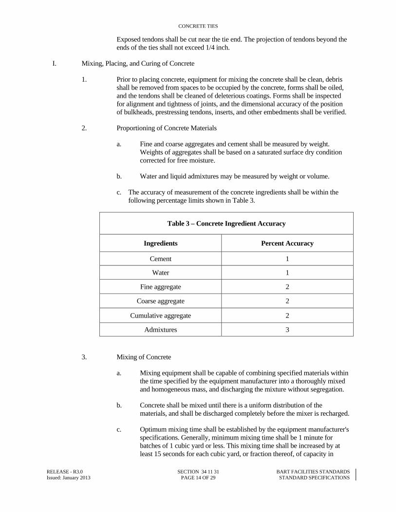
c. The accuracy of measurement of the concrete ingredients shall be within the following percentage limits shown in Table 3.
Table 3 – Concrete Ingredient Accuracy
Ingredients Percent Accuracy
Cement 1
Water 1
Fine aggregate 2
Coarse aggregate 2
Cumulative aggregate 2
Admixtures 3
3. Mixing of Concrete
a. Mixing equipment shall be capable of combining specified materials within the time specified by the equipment manufacturer into a thoroughly mixed and homogeneous mass, and discharging the mixture without segregation.
b. Concrete shall be mixed until there is a uniform distribution of the materials, and shall be discharged completely before the mixer is recharged.
c. Optimum mixing time shall be established by the equipment manufacturer's specifications. Generally, minimum mixing time shall be 1 minute for batches of 1 cubic yard or less. This mixing time shall be increased by at least 15 seconds for each cubic yard, or fraction thereof, of capacity in
CONCRETE TIES
RELEASE - R3.0 SECTION 34 11 31 BART FACILITIES STANDARDS Issued: January 2013 PAGE 15 OF 29 STANDARD SPECIFICATIONS
excess of one cubic yard. Mixing time shall be established for the silica fume concrete mix in order to produce batch-to-batch uniformity. Batch-to-batch uniformity shall be evaluated using the procedures described in Annex A.1, Concrete Uniformity Requirements, ASTM C94/C94M. Both under mixing and over mixing shall be avoided.
4. Conveying
a. Concrete shall be conveyed from the mixer to the place of final deposit in the shortest practicable time by methods that will prevent segregation or loss of materials.
b. Equipment for chuting, pumping, and pneumatic conveying of concrete shall be of size and design to assure flow of concrete at the delivery end without segregation of materials.
5. Depositing
a. Concrete shall be deposited as nearly as practical in its final position to avoid segregation due to re-handling or flowing. Concrete that has partially hardened or has been contaminated by foreign materials shall not be used.
b. Concrete shall not be placed when the ambient air temperature is below 40 degrees F. Concrete shall have a minimum temperature of 50 degrees F, and a maximum temperature of 90 degrees F. When concrete is placed at an ambient temperature of 90 degrees F or greater, special precautions to prevent rapid drying shall be employed. Comply with applicable requirements of ACI 305R.
6. Consolidating
a. Concrete shall be thoroughly consolidated by vibration during placement, and shall be thoroughly worked around the pre-stressing tendons, embedded inserts, and into the corners of the forms.
b. External form vibration or internal concrete vibration or a combination of both shall be used to obtain uniform mix, and shall be sufficient to yield concrete with a density of not less than 145 pounds per cubic foot.
c. Forms shall not be damaged during consolidation.
7. Curing
a. Ties shall be cured by steam, radiant heat, or other accepted curing process to accelerate strength gain so that removal of forms and transfer of the pre-stressing force may be accomplished at an early age.
b. Curing shall be performed in accordance with procedures established by the Pre-cast/Pre-stressed Concrete Institute to produce the concrete strengths specified. The pre-steam period shall be 3 to 4 hours. Temperature gradient shall not exceed 30 degrees F per hour. Maximum curing temperature shall not exceed 140 degrees F. Referenced temperatures are concrete, not ambient.
CONCRETE TIES
RELEASE - R3.0 SECTION 34 11 31 BART FACILITIES STANDARDS Issued: January 2013 PAGE 16 OF 29 STANDARD SPECIFICATIONS
8. Ties shall be removed from forms in a manner that will prevent damage to the forms or ties.
9. Finishing
a. Formed surfaces of the finished ties shall have a smooth and dense uniform surface. Surface of the rail seat shall have a smooth finish and shall be free from surface irregularities and excessive air holes. Other surfaces shall have a smooth finish that may contain honeycomb not to exceed 2 percent of the surface and a maximum void diameter and depth of 3/8 inch.
b. Bottom surface of the ties shall have a rough or coarse finish as may be obtained with a medium coarse broom or wood float.
c. Bottom corners of the ties shall have tooled 1/2 inch minimum radius or 1/2 inch by 45 degree chamfers.
d. Two ties, which in the opinion of the Engineer, show the required finishes shall be set aside as comparison standards for acceptance of the ties.
J. Acceptance Tests for CT and SPCT
1. Approval of the tie design is dependent upon the successful completion of the testing program needed. Retesting and redesign, if required, shall be at the fabricator's expense.
2. From a lot of not less than five ties produced in accordance with these Specifications, three ties will be selected at random by the Engineer for laboratory testing.
3. If required for design testing of the fastening system, the fabricator shall also furnish a section of a tie or a concrete block with rail seat and fastening system identical to the ties furnished for testing. The age of test ties or concrete block at time of testing shall be at least 7 days but not more than 28 days.
4. Each of the three ties, and if required the tie block, submitted for testing shall be carefully measured and examined to determine their compliance with the specified dimensions and tolerances. Upon satisfactory completion of the examination, two ties, designated as Tie No. 1 and Tie No. 2, shall be subjected to performance tests as specified herein. The remaining tie, which will be designated as Tie No. 3, will be retained by the fabricator for further test use and as a control for dimensional tolerances and surface appearance of ties subsequently produced.
K. Dimensions and Tolerances shall conform to that provided in Table 4.
CONCRETE TIES
RELEASE - R3.0 SECTION 34 11 31 BART FACILITIES STANDARDS Issued: January 2013 PAGE 17 OF 29 STANDARD SPECIFICATIONS
Table 4 – Concrete Tie Dimensional Tolerance
Dimension Tolerance
Nominal Length ±1/4”
Width of Bottom ±1/4”
Width of Top at Center of Rail seat ±1/8”
Maximum Top Corner Chamfer 1 inch by 45 degrees.
Depth at Center of Rail Seat ±1/16”
Depth at Center of Tie ±1/16”
Distance between the inside faces of the field embedded shoulder inserts +0”, -1/8”
Standard Concrete Tie Centerline ±1/8” of Track Gage Centerline
Standard Concrete Tie Rail Seat Cant 1 in 40 +1 degree, -0 degree
Concrete Special Trackwork Tie Rail Seat Cant 0 +1 degree, -0 degree
Rail Seat Differential Tilt ±1/16 inch in a width of 6 inches
Rail Seat Plane ±1/32”
Protrusion of Pretensioning Tendons +1/4”, -0”
L. Sequence of design performance tests using Tie no. 1 shall be as follows:
1. Rail seat Positive Bending Moment Test shall be performed on the two rail seats designated "A" and "B".
2. Center Negative Bending Moment Test.
3. Bond Development and Ultimate Load-Test shall be performed on Rail seat A.
M. Sequence of design performance tests using Tie No. 2 shall be as follows.
1. Rail Fastening Shoulder Test shall be performed on all shoulders.
2. Contact Rail Insert Test shall be performed on all inserts.
3. Rail Fastening Uplift Test shall be performed on one rail seat.
4. Electrical Resistance and Impedance Test.
CONCRETE TIES
RELEASE - R3.0 SECTION 34 11 31 BART FACILITIES STANDARDS Issued: January 2013 PAGE 18 OF 29 STANDARD SPECIFICATIONS
N. Rail Seat Positive Bending Moment Test: With the tie supported and loaded as indicated in Figure 1, a load P shall be applied in such a manner as to avoid shock until a load of 17,500 pounds is obtained. This load shall be held for not less than 3 minutes, during which time an inspection shall be made to determine if structural cracking occurs. Structural cracking is defined in the AREMA Manual. A five-power magnifying glass shall be used to locate cracks. If structural cracking does not occur, the requirements of this test will have been met.
O. Center Negative Bending Moment Test: With the tie supported and loaded as indicated in Figure 2, a load P shall be applied at a uniform rate and in such a manner as to avoid shock until a load of 7,500 pounds is obtained. This load shall be held for not less than 3 minutes, during which time an inspection shall be made to determine if structural cracking occurs. Structural cracking is defined in the AREMA Manual. A five-power magnifying glass shall be used to locate cracks. If structural cracking does not occur, the requirements of this test will have been met.
P. Bond Development and Ultimate Load Test: With the tie supported and loaded as indicated in Figure 1, a load P shall be applied as specified herein, and increased until a load of 26,250 pounds is obtained. The load shall be held for not less than 3 minutes. If there is no more than 0.001 inch strand slippage determined by an extensometer reading to 0.0001 inch, the requirements of this test will have been met. The measurements shall be made on the outermost tendons of the lower layer. The load P shall be increased until ultimate failure occurs. The ultimate failure so obtained shall exceed 29,750 pounds.
Q. Daily Production Quality Control Tests.
1. The distance between the inside faces of the field embedded shoulder inserts, the height of all embedded shoulder inserts and contact rail insert location shall be verified on every tie, and, by use of a templates.
2. One tie selected at random from each lot of 200 ties or fraction thereof produced each day shall be subjected to the following tests:
3. The rail seat Positive Bending Moment Test as specified in herein, shall be performed on both rail seats. Ties that pass testing requirements and are not structurally cracked or otherwise damaged will be accepted. All other ties shall be rejected.
4. All ties in the lot will be accepted if the test tie passes the above tests. If the test tie fails either of the tests, two additional ties from the same lot shall be subjected to the same test, and acceptance of the lot shall be based on the following conditions.
a. If both retest ties meet the test requirement, the lot will be accepted.
b. If either of the retest ties fails to meet the test requirements, two additional ties from each line shall be selected. (A line is defined as one form cavity wide by the number of forms, end-to-end.) The two additional ties shall be subjected to the tests, and if both ties meet the test requirements, that line of ties will be accepted. If either of the ties fails to meet the test requirements, the entire line shall be rejected or each individual tie in the line shall be tested in order to determine if the test requirements have been met. Ties meeting the requirements will be accepted.
R. In addition to the production quality control tests outlined above, the following tests shall be performed.
CONCRETE TIES
RELEASE - R3.0 SECTION 34 11 31 BART FACILITIES STANDARDS Issued: January 2013 PAGE 19 OF 29 STANDARD SPECIFICATIONS
1. One tie selected at random from every 1,000 ties produced and accepted on the basis of meeting the requirements herein, shall be tested for bond development and ultimate strength as specified herein.
2. If either of the retest ties fails to meet the test requirements, three additional ties from each line shall be selected. The three additional ties shall be subjected to the tests, and if the three ties meet the test requirements, that line of ties will be accepted. If any of the ties fails to meet the test requirements, the entire line shall be rejected or each individual tie in the line shall tested in order to determine if the test requirements have been met. Ties meeting the requirements will be accepted.
S. Design qualification testing of the fastening system consists of testing components cast into the ties in addition to tests conducted on the external components as specified below. The rail fastening system shall conform to the testing requirements, herein, in all positions of lateral adjustment.
T. Sequence of design tests shall be as follows.
1. Rail Fastening Repeated Load Test.
2. Rail Fastening Longitudinal Restraint Test.
3. Rail Fastening Lateral Restraint Test.
U. Rail Fastening Shoulder Test.
1. The following test shall be performed on each shoulder as indicated in Figure 3 to determine the ability of shoulders to resist tension. An axial load P of 8000 pounds shall be applied to each shoulder separately and shall be held for not less than three minutes. The embedded shoulder shall not move and the concrete shall not crack, as observed by visual inspection. Separation of laitance surrounding the shoulder will not be cause for rejection.
2. Following successful completion of the shoulder pull-out test, the torque test shall be performed on each shoulder. A torque of 250 foot-pounds shall be applied about the vertical axis of the shoulder by means of a calibrated torque wrench and a suitable attachment to the shoulder. The torque shall be held for not less than 3 minutes. Ability of the shoulder to resist this torque without rotation, cracking of concrete, or permanent deformation shall constitute passage of this test.
V. The following test shall be performed on each contact rail insert in a manner similar to Figure 3 to determine the ability of inserts to resist tension when the surrounding concrete is unrestrained. An axial load P of 3500 pounds shall be applied to each insert separately and shall be held for not less than three minutes. The embedded insert shall not move and the concrete shall not crack, as observed by visual inspection. Separation of laitance surrounding the insert will not be cause for rejection.
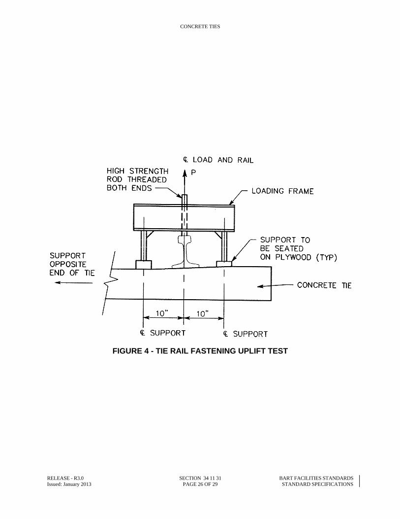
W. Rail Fastening Uplift Test: An 18 inch to 20 inch section of 119 RE rail shall be secured to one rail seat using a complete rail fastening system including pads, clips, and associated hardware, as recommended by the manufacturer of the rail fastening system. In accordance with the loading diagram in Figure 4, an incremental load shall be applied to the rail. The load "P" at which separation of the rail from pad or pad from rail seat occurs (whichever occurs first) shall be recorded. The load shall then be completely released. A load of 1.5P shall then be applied. The
CONCRETE TIES
RELEASE - R3.0 SECTION 34 11 31 BART FACILITIES STANDARDS Issued: January 2013 PAGE 20 OF 29 STANDARD SPECIFICATIONS
shoulders shall not pull out or loosen in the concrete, and no component of the fastening system shall fracture nor shall the rail be released.
X. Rail Fastening Repeated Load Test
1. An 18 inch to 20 inch section of 119 RE rail, from which loose mill scale has been removed by wiping with a cloth, shall be secured to the rail seat using a complete rail fastening assembly. In accordance with the loading diagram in Figure 4, determine the load "P" that will cause separation of the rail from the rail seat pad or the pad from the rail seat, whichever occurs first. This load may be determined during the Fastening Uplift Test specified herein, in which case a new set of fastening clips shall be used for the repeated load test.
2. An 18 inch to 20 inch section of 119 RE rail, from which loose mill scale has been removed by wiping with a cloth, shall be secured to the rail seat using a complete rail fastening assembly. In accordance with the loading diagram in Figure 5, alternating downward and upward loads shall be applied at an angle of 20 degrees to the vertical axis of the rail at a rate not to exceed 300 cycles per minute for three million cycles. The rail shall be free to rotate under the applied loads. One cycle shall consist of both a downward and upward load. The magnitude of the upward load shall be 0.6P. If springs are used to generate the upward load, the downward load shall be 17,000 pounds plus 0.6P. If a double-acting hydraulic ram is used to generate both the upward and the downward load, the downward load shall be 17,000 pounds.
3. The repeated load test may generate heat in elastomeric rail seat pads. Heat build-up in such pads shall not be permitted to exceed 120 degrees F. Heat build-up may be controlled by reducing the rate of load application or by providing periods of rest to allow cooling of the pad.
4. Rupture failure of any component of the fastening system shall constitute failure of the test.
Y. Rail Fastening Longitudinal Restraint Test: After successful completion of the Rail Fastening Repeated Load Test specified herein, and without disturbing the rail fastening assembly in any manner, the tie and fastening shall be subjected to a longitudinal restraint test in both directions. A longitudinal load shall be applied as indicated in Figure 6, in increments of 400 pounds with readings taken of longitudinal rail displacement after each increment. Readings of rail displacement shall be the average of the readings of two dial indicators reading 0.001 inch. One dial indicator shall be placed on each side of the rail with the dial indicator plungers parallel to the longitudinal axis of the rail. The load shall be increased incrementally until a load of 2400 pounds is reached. This specified load shall be held for not less than 15 minutes. The rail shall not move more than 1/8 inch during this period. The fastening shall be capable of meeting the requirements of this test in either direction of loading. The tie and fastenings will have successfully passed this test if the specified criteria are met.
Z. Rail Fastening Lateral Restraint Test
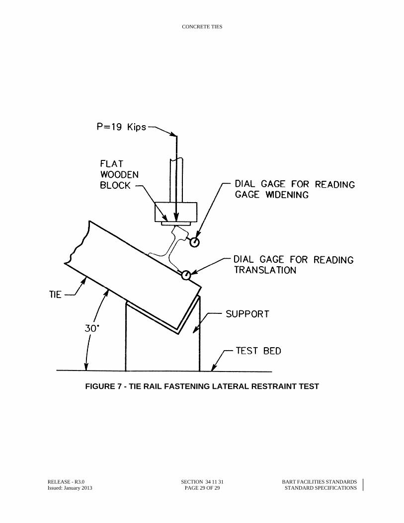
1. An 18 inch to 20 inch section of 119 RE rail shall be secured to the tie block in a manner appropriate to the fastening being used. The entire assembly shall be supported and loaded as indicated in Figure 7. The loading head shall be fixed against translation and rotation. The wood block shall be 10 inches by 10 inches by 3/4 inch thick, five-ply exterior grade plywood.
CONCRETE TIES
RELEASE - R3.0 SECTION 34 11 31 BART FACILITIES STANDARDS Issued: January 2013 PAGE 21 OF 29 STANDARD SPECIFICATIONS
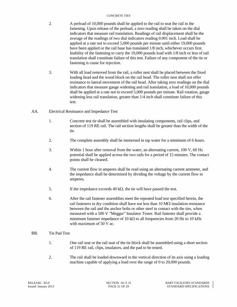
2. A preload of 10,000 pounds shall be applied to the rail to seat the rail in the fastening. Upon release of the preload, a zero reading shall be taken on the dial indicators that measure rail translation. Readings of rail displacement shall be the average of the readings of two dial indicators reading 0.001 inch. Load shall be applied at a rate not to exceed 5,000 pounds per minute until either 19,000 pounds have been applied or the rail base has translated 1/8 inch, whichever occurs first. Inability of the fastening to carry the 19,000 pounds load with 1/8 inch or less of rail translation shall constitute failure of this test. Failure of any component of the tie or fastening is cause for rejection.
3. With all load removed from the rail, a roller nest shall be placed between the fixed loading head and the wood block on the rail head. The roller nest shall not offer resistance to lateral movement of the rail head. After taking zero readings on the dial indicators that measure gauge widening and rail translation, a load of 10,000 pounds shall be applied at a rate not to exceed 5,000 pounds per minute. Rail rotation, gauge widening less rail translation, greater than 1/4 inch shall constitute failure of this test.
AA. Electrical Resistance and Impedance Test
1. Concrete test tie shall be assembled with insulating components, rail clips, and section of 119 RE rail. The rail section lengths shall be greater than the width of the tie.
2. The complete assembly shall be immersed in tap water for a minimum of 6 hours.
3. Within 1 hour after removal from the water, an alternating current, 100 V, 60 Hz potential shall be applied across the two rails for a period of 15 minutes. The contact points shall be cleaned.
4. The current flow in amperes shall be read using an alternating current ammeter, and the impedance shall be determined by dividing the voltage by the current flow in amperes.
5. If the impedance exceeds 40 k, the tie will have passed the test.
6. After the rail fastener assemblies meet the repeated load test specified herein, the rail fasteners in dry condition shall have not less than 10 M insulation resistance between the rail and the anchor bolts or other steel in contact with the ties, when measured with a 500 V "Megger" Insulator Tester. Rail fastener shall provide a minimum fastener impedance of 10 k to all frequencies from 20 Hz to 10 kHz with maximum of 50 V ac.
BB. Tie Pad Test
1. One rail seat or the rail seat of the tie block shall be assembled using a short section of 119 RE rail, clips, insulators, and the pad to be tested.
2. The rail shall be loaded downward in the vertical direction of its axis using a loading machine capable of applying a load over the range of 0 to 20,000 pounds.
CONCRETE TIES
RELEASE - R3.0 SECTION 34 11 31 BART FACILITIES STANDARDS Issued: January 2013 PAGE 22 OF 29 STANDARD SPECIFICATIONS
3. Displacement devices shall be attached to the rail capable of measuring vertical displacements of 0.0001 inch. Devices shall be located at the four corners of the pad.
4. Load shall be increased, at a rate between 3,000 and 6,000 pounds per minute, from 0 to 20,000 pounds in 1,000 pound increments. Deflection at each increment shall be read on the four measuring devices, averaged and recorded. Sufficient time shall be allowed at each increment of loading for the deflection to stabilize.
5. Measure and record the time in seconds during both the loading and unloading cycle.
6. At the completion of the loading cycle, the load shall be decreased, at a rate between 3,000 and 6,000 pounds per minute, in 1,000-pound increments, recording and averaging deflection as before.
7. Plot load versus deflection for the loading and unloading cycles.
8. Draw a line between zero and the 16,000-pound point for the loading and unloading load-deflection curves.
9. Calculate the slope of each line.
10. The requirements of this test shall have been met if when
a. The slope of each line is between 1 by 106 and 2 by 106 pounds per inch, and
b. The pad returns to within 0.002 inch of its original position within 10 seconds after removal of the final increment of load.
PART 3 - EXECUTION
3.01 INSTALLATION
A. Install concrete ties in accordance with the respective manufacturer's recommended installation instructions and procedures and as provided, except as modified herein.
B. Install concrete ties in accordance with the requirements of Section 34 05 17, Common Work Results for Trackway.
END OF SECTION 34 11 31
FIGURES FOLLOW
CONCRETE TIES
RELEASE - R3.0 SECTION 34 11 31 BART FACILITIES STANDARDS Issued: January 2013 PAGE 23 OF 29 STANDARD SPECIFICATIONS
FIGURE 1 - TIE RAIL SEAT POSITIVE BENDING MOMENT TEST
CONCRETE TIES
RELEASE - R3.0 SECTION 34 11 31 BART FACILITIES STANDARDS Issued: January 2013 PAGE 24 OF 29 STANDARD SPECIFICATIONS
FIGURE 2 - TIE CENTER NEGATIVE BENDING MOMENT TEST
CONCRETE TIES
RELEASE - R3.0 SECTION 34 11 31 BART FACILITIES STANDARDS Issued: January 2013 PAGE 25 OF 29 STANDARD SPECIFICATIONS
FIGURE 3 - TIE RAIL FASTENING SHOULDER AND CONTACT RAIL INSERT PULLOUT TEST
CONCRETE TIES
RELEASE - R3.0 SECTION 34 11 31 BART FACILITIES STANDARDS Issued: January 2013 PAGE 26 OF 29 STANDARD SPECIFICATIONS
FIGURE 4 - TIE RAIL FASTENING UPLIFT TEST
CONCRETE TIES
RELEASE - R3.0 SECTION 34 11 31 BART FACILITIES STANDARDS Issued: January 2013 PAGE 27 OF 29 STANDARD SPECIFICATIONS
FIGURE 5 - TIE RAIL FASTENING REPEATED LOAD TEST
CONCRETE TIES
RELEASE - R3.0 SECTION 34 11 31 BART FACILITIES STANDARDS Issued: January 2013 PAGE 28 OF 29 STANDARD SPECIFICATIONS
FIGURE 6 - TIE RAIL FASTENING LONGITUDINAL RESTRAINT TEST
CONCRETE TIES
RELEASE - R3.0 SECTION 34 11 31 BART FACILITIES STANDARDS Issued: January 2013 PAGE 29 OF 29 STANDARD SPECIFICATIONS
FIGURE 7 - TIE RAIL FASTENING LATERAL RESTRAINT TEST