27
11/30/2004 Tommi Heikkilä S-72.333 Postgraduate Course in Radio Communications 1 C D M A Code Division Multiple Access

11/30/2004 Tommi HeikkiläS-72.333 Postgraduate Course in Radio Communications
1
C D M ACode Division Multiple Access
11/30/2004 Tommi HeikkiläS-72.333 Postgraduate Course in Radio Communications
2
Agenda• Introduction• History of Spread-Spectrum and CDMA• Introduction to DS-CDMA• Cellular CDMA• CDMA Capacity• CDMA Cellular Applications• Conclusions• References• Homework
11/30/2004 Tommi HeikkiläS-72.333 Postgraduate Course in Radio Communications
3
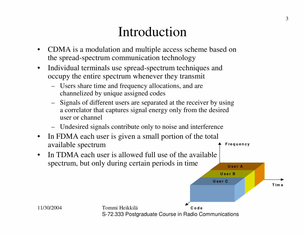
Introduction• CDMA is a modulation and multiple access scheme based on
the spread-spectrum communication technology• Individual terminals use spread-spectrum techniques and
occupy the entire spectrum whenever they transmit– Users share time and frequency allocations, and are
channelized by unique assigned codes– Signals of different users are separated at the receiver by using
a correlator that captures signal energy only from the desired user or channel
– Undesired signals contribute only to noise and interference• In FDMA each user is given a small portion of the total
available spectrum• In TDMA each user is allowed full use of the available
spectrum, but only during certain periods in time
F re q u e n c y
T im e
C o d e
H ig h d a ta ra t e u s e r
U s e r C
U s e r A
U s e r B
11/30/2004 Tommi HeikkiläS-72.333 Postgraduate Course in Radio Communications
4
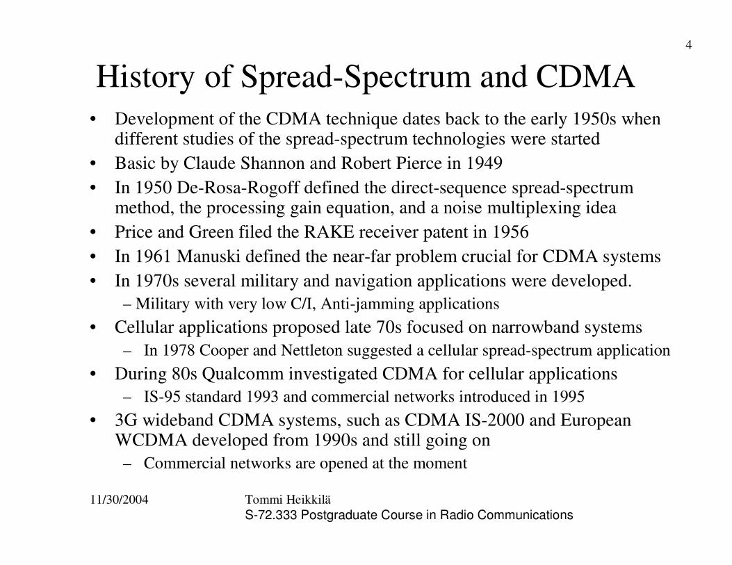
History of Spread-Spectrum and CDMA• Development of the CDMA technique dates back to the early 1950s when
different studies of the spread-spectrum technologies were started• Basic by Claude Shannon and Robert Pierce in 1949• In 1950 De-Rosa-Rogoff defined the direct-sequence spread-spectrum
method, the processing gain equation, and a noise multiplexing idea• Price and Green filed the RAKE receiver patent in 1956• In 1961 Manuski defined the near-far problem crucial for CDMA systems• In 1970s several military and navigation applications were developed.
– Military with very low C/I, Anti-jamming applications• Cellular applications proposed late 70s focused on narrowband systems
– In 1978 Cooper and Nettleton suggested a cellular spread-spectrum application• During 80s Qualcomm investigated CDMA for cellular applications
– IS-95 standard 1993 and commercial networks introduced in 1995• 3G wideband CDMA systems, such as CDMA IS-2000 and European
WCDMA developed from 1990s and still going on– Commercial networks are opened at the moment

11/30/2004 Tommi HeikkiläS-72.333 Postgraduate Course in Radio Communications
5
Spread-Spectrum Technology (1)• Originally developed for military and navigation purposes
– secure means of communication in hostile environments – Low Probability of Interception
• Cannot be easily detected by enemy communication equipment due to low power spectral density, even lower than background noise
– Anti-Jamming• Properties to combat intentional interference trying to sabotage
communication systems
• Nowadays feasible for commercial applications especially for mobile communication systems– It provides an efficient multiple access method for a number of
independent users sharing a common communication channel withoutexternal synchronization methods
– DS-CDMA is probably the most interesting multiple access method provided by spread-spectrum technology
11/30/2004 Tommi HeikkiläS-72.333 Postgraduate Course in Radio Communications
6
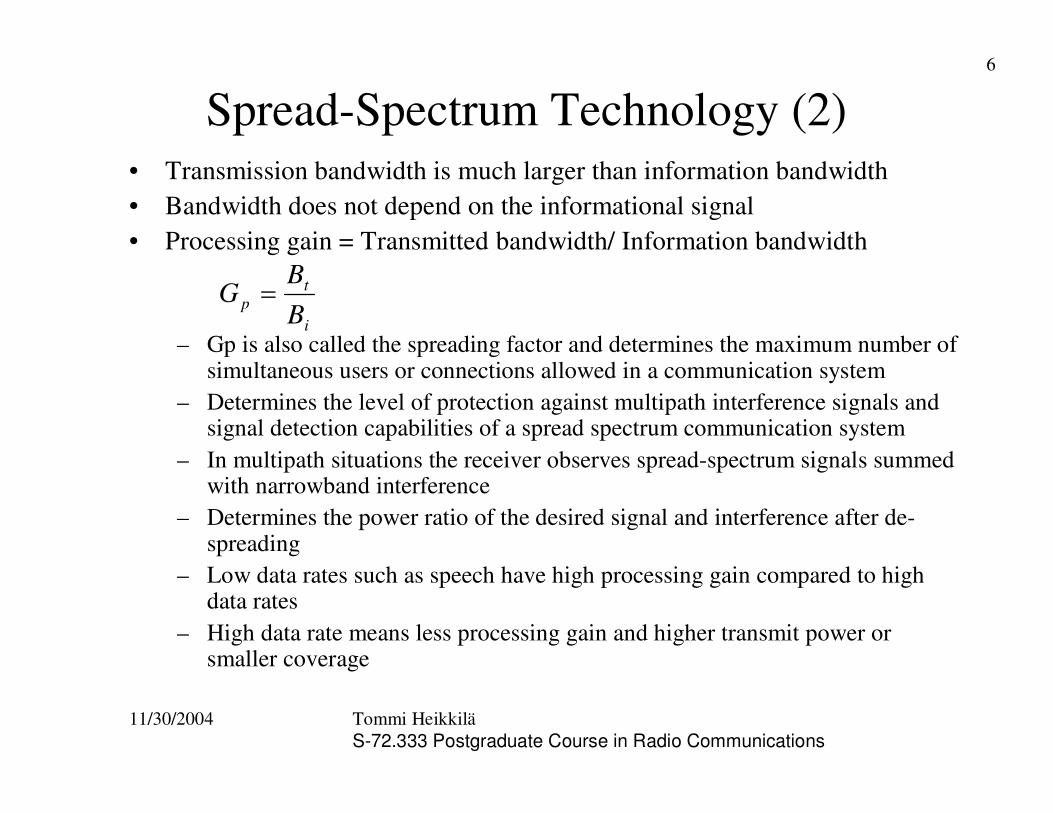
Spread-Spectrum Technology (2)• Transmission bandwidth is much larger than information bandwidth• Bandwidth does not depend on the informational signal• Processing gain = Transmitted bandwidth/ Information bandwidth
– Gp is also called the spreading factor and determines the maximum number of simultaneous users or connections allowed in a communication system
– Determines the level of protection against multipath interference signals and signal detection capabilities of a spread spectrum communication system
– In multipath situations the receiver observes spread-spectrum signals summed with narrowband interference
– Determines the power ratio of the desired signal and interference after de-spreading
– Low data rates such as speech have high processing gain compared to high data rates
– High data rate means less processing gain and higher transmit power or smaller coverage
i
tp B
BG �
11/30/2004 Tommi HeikkiläS-72.333 Postgraduate Course in Radio Communications
7
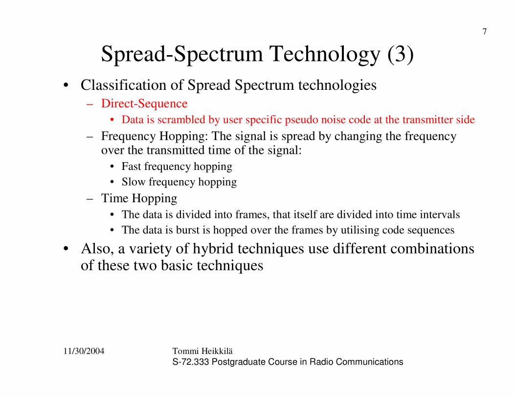
Spread-Spectrum Technology (3)• Classification of Spread Spectrum technologies
– Direct-Sequence• Data is scrambled by user specific pseudo noise code at the transmitter side
– Frequency Hopping: The signal is spread by changing the frequency over the transmitted time of the signal:
• Fast frequency hopping• Slow frequency hopping
– Time Hopping• The data is divided into frames, that itself are divided into time intervals • The data is burst is hopped over the frames by utilising code sequences
• Also, a variety of hybrid techniques use different combinations of these two basic techniques
11/30/2004 Tommi HeikkiläS-72.333 Postgraduate Course in Radio Communications
8
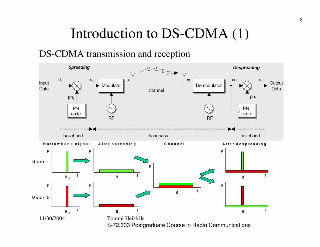
Introduction to DS-CDMA (1)DS-CDMA transmission and reception
B i
B i
B t
U s e r 1
U s e r 2
A f t e r s p r e a d i n g N a r r o w b a n d s i g n a l
B t
C h a n n e l
B t
A f t e r d e s p r e a d i n g
B i
B i
P
P P
P
P
P
P
f
f f
f f f
f
11/30/2004 Tommi HeikkiläS-72.333 Postgraduate Course in Radio Communications
9
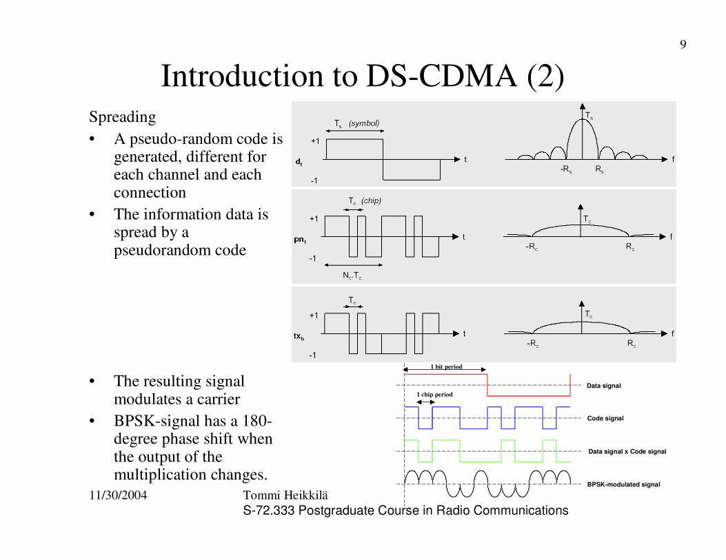
Introduction to DS-CDMA (2)Spreading• A pseudo-random code is
generated, different for each channel and each connection
• The information data is spread by a pseudorandom code
• The resulting signal modulates a carrier
• BPSK-signal has a 180-degree phase shift when the output of the multiplication changes.
Data signal
Code signal
Data signal x Code signal
BPSK-modulated signal
1 chip period
1 bit period
11/30/2004 Tommi HeikkiläS-72.333 Postgraduate Course in Radio Communications
10
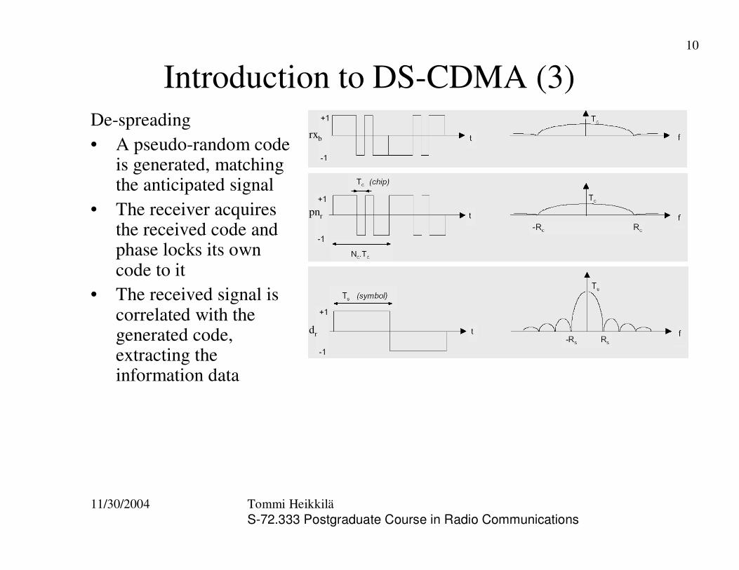
Introduction to DS-CDMA (3)De-spreading• A pseudo-random code
is generated, matching the anticipated signal
• The receiver acquires the received code and phase locks its own code to it
• The received signal is correlated with the generated code, extracting the information data
rxb
pnr
dr
11/30/2004 Tommi HeikkiläS-72.333 Postgraduate Course in Radio Communications
11
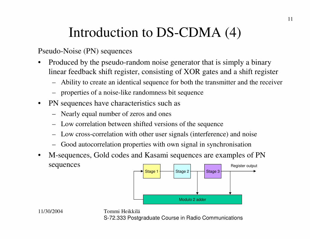
Introduction to DS-CDMA (4)Pseudo-Noise (PN) sequences• Produced by the pseudo-random noise generator that is simply a binary
linear feedback shift register, consisting of XOR gates and a shift register– Ability to create an identical sequence for both the transmitter and the receiver– properties of a noise-like randomness bit sequence
• PN sequences have characteristics such as– Nearly equal number of zeros and ones– Low correlation between shifted versions of the sequence– Low cross-correlation with other user signals (interference) and noise– Good autocorrelation properties with own signal in synchronisation
• M-sequences, Gold codes and Kasami sequences are examples of PN sequences
Stage 1 Stage 2 Stage 3
Modulo 2 adder
Register output
11/30/2004 Tommi HeikkiläS-72.333 Postgraduate Course in Radio Communications
12
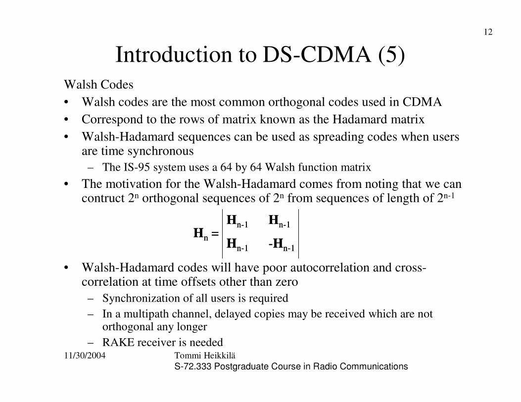
Introduction to DS-CDMA (5)Walsh Codes• Walsh codes are the most common orthogonal codes used in CDMA• Correspond to the rows of matrix known as the Hadamard matrix• Walsh-Hadamard sequences can be used as spreading codes when users
are time synchronous– The IS-95 system uses a 64 by 64 Walsh function matrix
• The motivation for the Walsh-Hadamard comes from noting that we can contruct 2n orthogonal sequences of 2n from sequences of length of 2n-1
• Walsh-Hadamard codes will have poor autocorrelation and cross-correlation at time offsets other than zero– Synchronization of all users is required– In a multipath channel, delayed copies may be received which are not
orthogonal any longer– RAKE receiver is needed
Hn =Hn-1 Hn-1
Hn-1 -Hn-1
Hn =Hn-1 Hn-1
Hn-1 -Hn-1
11/30/2004 Tommi HeikkiläS-72.333 Postgraduate Course in Radio Communications
13
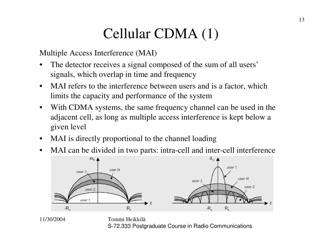
Cellular CDMA (1)Multiple Access Interference (MAI)• The detector receives a signal composed of the sum of all users’
signals, which overlap in time and frequency• MAI refers to the interference between users and is a factor, which
limits the capacity and performance of the system• With CDMA systems, the same frequency channel can be used in the
adjacent cell, as long as multiple access interference is kept below a given level
• MAI is directly proportional to the channel loading• MAI can be divided in two parts: intra-cell and inter-cell interference
11/30/2004 Tommi HeikkiläS-72.333 Postgraduate Course in Radio Communications
14
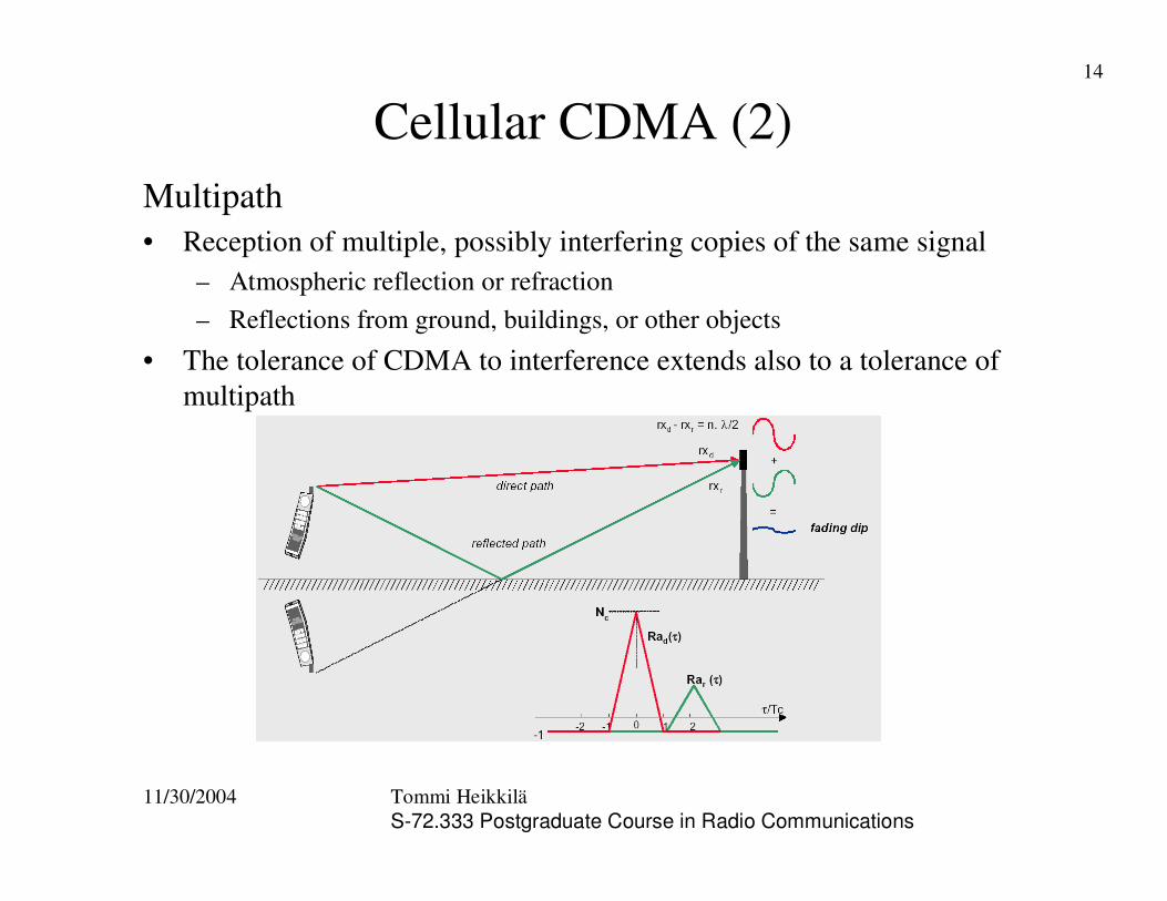
Cellular CDMA (2)Multipath• Reception of multiple, possibly interfering copies of the same signal
– Atmospheric reflection or refraction– Reflections from ground, buildings, or other objects
• The tolerance of CDMA to interference extends also to a tolerance of multipath
11/30/2004 Tommi HeikkiläS-72.333 Postgraduate Course in Radio Communications
15
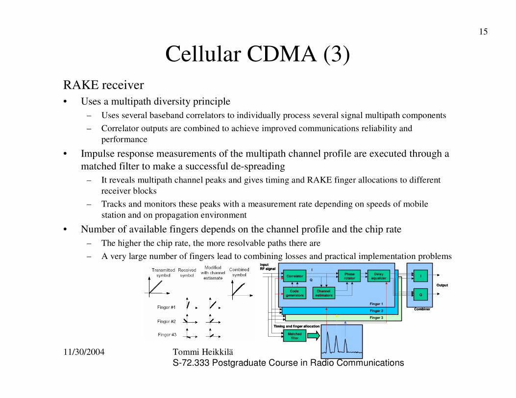
Cellular CDMA (3)RAKE receiver• Uses a multipath diversity principle
– Uses several baseband correlators to individually process several signal multipath components– Correlator outputs are combined to achieve improved communications reliability and
performance
• Impulse response measurements of the multipath channel profile are executed through a matched filter to make a successful de-spreading
– It reveals multipath channel peaks and gives timing and RAKE finger allocations to different receiver blocks
– Tracks and monitors these peaks with a measurement rate depending on speeds of mobile station and on propagation environment
• Number of available fingers depends on the channel profile and the chip rate– The higher the chip rate, the more resolvable paths there are– A very large number of fingers lead to combining losses and practical implementation problems
Correlator Phaserotator
Delayequalizer
Code generators
Channel estimators
I
Q
I
Q
CombinerFinger 1
Finger 3
Finger 2
Matchedfilter
Input RF signal
Timing and finger allocation
Output
Correlator Phaserotator
Delayequalizer
Code generators
Channel estimators
I
Q
I
Q
CombinerFinger 1
Finger 3
Finger 2
Matchedfilter
Input RF signal
Timing and finger allocation
Output
11/30/2004 Tommi HeikkiläS-72.333 Postgraduate Course in Radio Communications
16
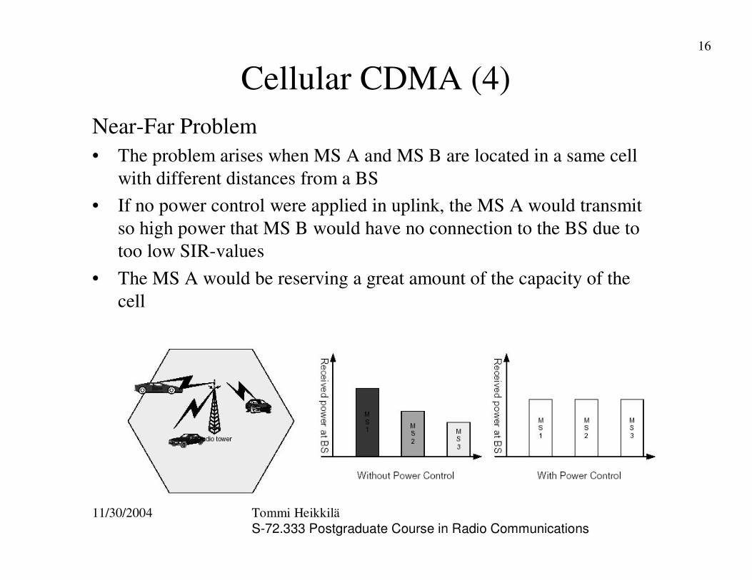
Cellular CDMA (4)Near-Far Problem• The problem arises when MS A and MS B are located in a same cell
with different distances from a BS• If no power control were applied in uplink, the MS A would transmit
so high power that MS B would have no connection to the BS due to too low SIR-values
• The MS A would be reserving a great amount of the capacity of the cell
11/30/2004 Tommi HeikkiläS-72.333 Postgraduate Course in Radio Communications
17
Cellular CDMA (5)Power Control• Power control is an extremely essential function when considering the
smooth operation and the capacity of CDMA-based systems• The power control problem arises due to multiple access interference• Each user looks like random noise to other users and causes
unnecessary interference to the system• Power control is implemented to overcome the near-far problem and to
maximize the capacity of the system– It tries to control the powers of the mobile stations in the system so that
the received powers at the base station stay equal– It tries also to compensate the effects of slow fading and fast fading– There is no near-far problem in downlink due to a one-to-many situation
• Power control forces all users to transmit the minimum amount ofpower needed to achieve acceptable signal quality at the base station
11/30/2004 Tommi HeikkiläS-72.333 Postgraduate Course in Radio Communications
18
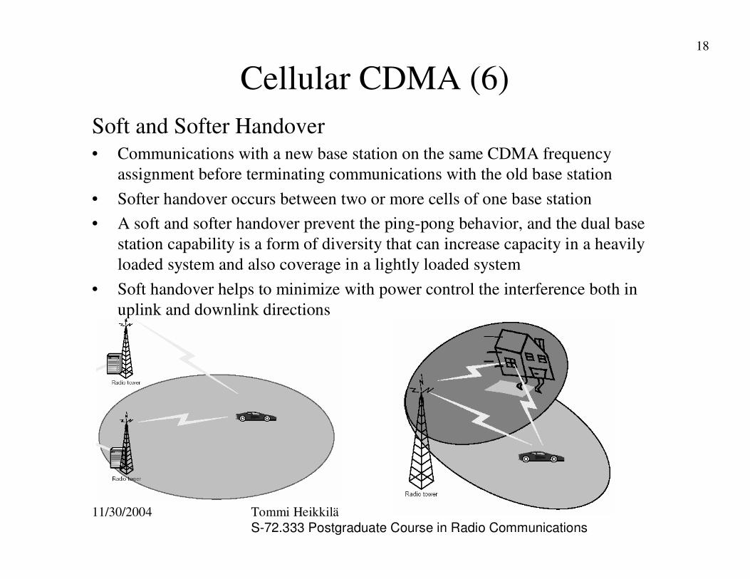
Cellular CDMA (6)Soft and Softer Handover• Communications with a new base station on the same CDMA frequency
assignment before terminating communications with the old base station• Softer handover occurs between two or more cells of one base station• A soft and softer handover prevent the ping-pong behavior, and the dual base
station capability is a form of diversity that can increase capacity in a heavily loaded system and also coverage in a lightly loaded system
• Soft handover helps to minimize with power control the interference both in uplink and downlink directions
11/30/2004 Tommi HeikkiläS-72.333 Postgraduate Course in Radio Communications
19
CDMA Capacity (1)• Can be defined as throughput of bits or as the amount of simultaneous users in
the network receiving voice and data services with certain predefined quality targets
• Interfering signals caused by users to each other rise, as the amount of users gets higher in the network
• A balance between maintaining connection integrity and restricting interference level is maintained by controlling the power of each user so that signals arrive at their intended receiver with minimum required SIR-level
• Interference, coverage, and capacity are coupled tightly to together• Capacity can be restricted by either transmission power constraints or by the
self-generated interference– In the uplink, the system reaches its capacity when a mobile station does not have
enough power to overcome interference from the network, or a predefined loading target of the network is met
– In the downlink, capacity is reached when no additional power is available to add new users
– The power needed for either link is fundamentally related to Eb/No requirements for different services
11/30/2004 Tommi HeikkiläS-72.333 Postgraduate Course in Radio Communications
20
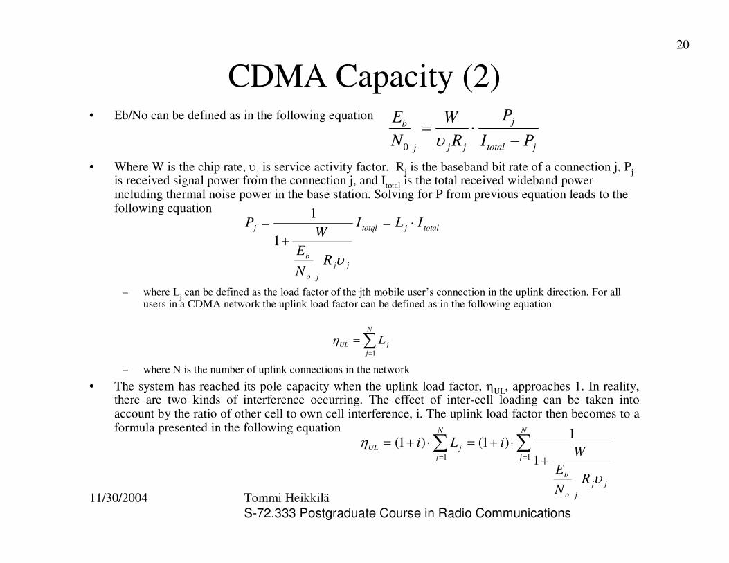
CDMA Capacity (2)• Eb/No can be defined as in the following equation
• Where W is the chip rate, �j is service activity factor, Rj is the baseband bit rate of a connection j, Pjis received signal power from the connection j, and Itotal is the total received wideband power including thermal noise power in the base station. Solving for P from previous equation leads to the following equation
– where Lj can be defined as the load factor of the jth mobile user’s connection in the uplink direction. For all users in a CDMA network the uplink load factor can be defined as in the following equation
– where N is the number of uplink connections in the network
• The system has reached its pole capacity when the uplink load factor, �UL, approaches 1. In reality, there are two kinds of interference occurring. The effect of inter-cell loading can be taken into account by the ratio of other cell to own cell interference, i. The uplink load factor then becomes to a formula presented in the following equation
jtotal
j
jjj
b
PI
P
RW
NE
���
�0
totaljtotql
jjjo
b
j ILI
RNE
WP ��
�
�
�
1
1
��
�N
jjUL L
1
�
���� �
������N
j
jjjo
b
N
jjUL
RNE
WiLi
11 1
1)1()1(
�
�
11/30/2004 Tommi HeikkiläS-72.333 Postgraduate Course in Radio Communications
21
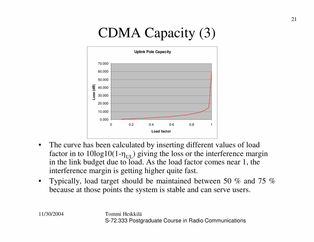
CDMA Capacity (3)
• The curve has been calculated by inserting different values of load factor in to 10log10(1-�UL) giving the loss or the interference margin in the link budget due to load. As the load factor comes near 1, the interference margin is getting higher quite fast.
• Typically, load target should be maintained between 50 % and 75 % because at those points the system is stable and can serve users.
Uplink Pole Capacity
0.000
10.000
20.000
30.000
40.000
50.000
60.000
70.000
0 0.2 0.4 0.6 0.8 1
Load factor
Loss
(dB
)
11/30/2004 Tommi HeikkiläS-72.333 Postgraduate Course in Radio Communications
22
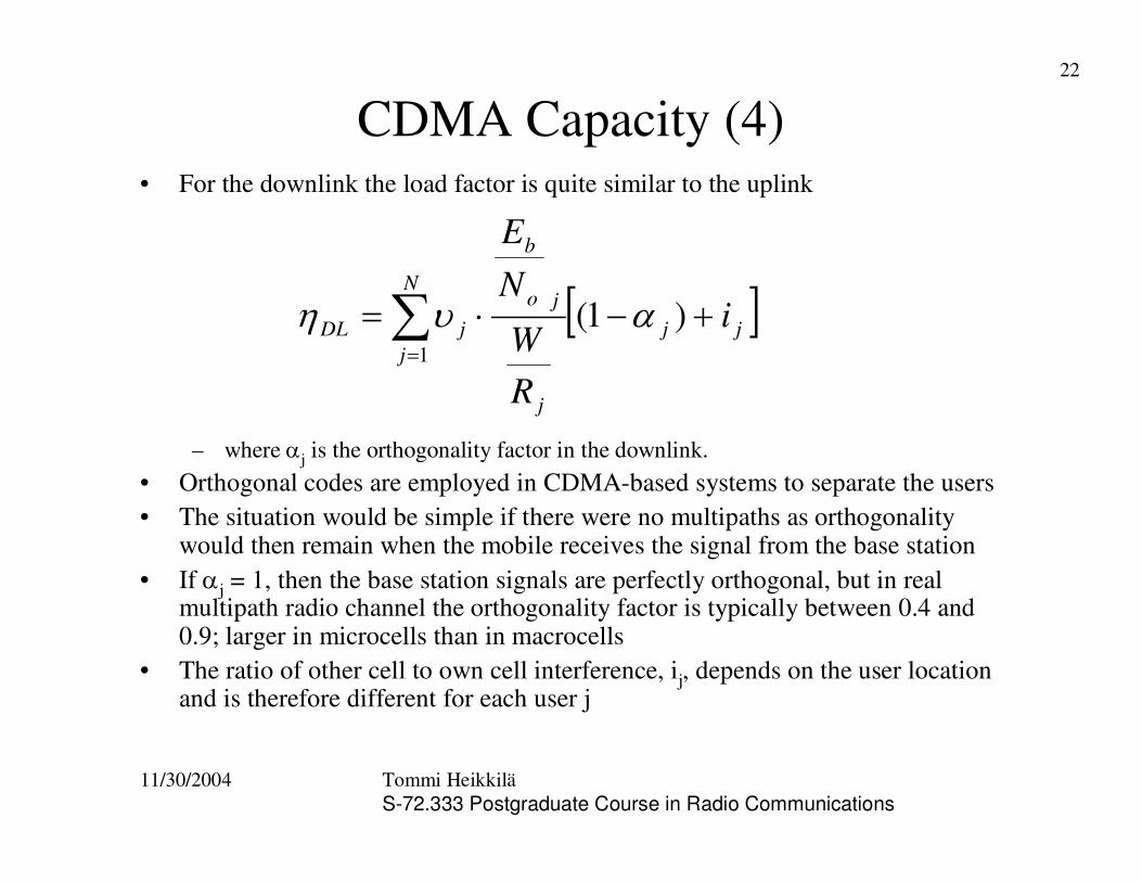
CDMA Capacity (4)• For the downlink the load factor is quite similar to the uplink
– where �j is the orthogonality factor in the downlink. • Orthogonal codes are employed in CDMA-based systems to separate the users• The situation would be simple if there were no multipaths as orthogonality
would then remain when the mobile receives the signal from the base station • If �j = 1, then the base station signals are perfectly orthogonal, but in real
multipath radio channel the orthogonality factor is typically between 0.4 and 0.9; larger in microcells than in macrocells
• The ratio of other cell to own cell interference, ij, depends on the user location and is therefore different for each user j
jj
N
j
j
jo
b
jDL i
RW
NE
���� ��
)1(1
���
11/30/2004 Tommi HeikkiläS-72.333 Postgraduate Course in Radio Communications
23
CDMA Cellular Applications (1)IS-95• Standard was finished in 1993 and first commercially launched in 1996 • Basic data rate is 9,6 kbps• Chip rate of 1.2288 Mchips/s• Allocated bandwidth is 1.25 MHz• The IS-95B is packet data enhancement like GPRS is to GSM system
– “cdmaOne” was launched in 1999 with data rates up to 115,5 kbps
• Fixed spreading code of length 64; repeating bits provides lower data rates• Uses pilot channel in downlink direction to provide synchronization, channel
tracking, and handover functions• In the uplink direction, orthogonal modulation is used, which permits the more
robust noncoherent demodulation to be used • In IS-95, all base stations use the same scrambling code (short code) to
distinguish among their transmissions, but with different timing offsets– GPSS receiver in every base station provides base station synchronization.
11/30/2004 Tommi HeikkiläS-72.333 Postgraduate Course in Radio Communications
24
CDMA Cellular Applications (2)CDMA2000• The third generation evolution phase of IS-95A/B• It can offer up to 307 kbps data rates (compare to EDGE)• CDMA2000 can use same 1.25 MHz as IS-95/cdmaOne
1xEV-DO/DV• 1xEVDO (Data Only) and 1xEVDV (Data&Voice)• Can offer high-speed data rates from 2,4 Mbps to 3,09 Mbps
WCDMA• The faster chip rate of 3,84 Mchips/s implies that WCDMA receiver can provide greater
multipath resolution and with a RAKE receiver, this implies greater frequency diversity due to wider bandwidth, 5 MHz
• Data rates up to 384 kbps for circuit switched and up to 2 Mbps for packet switched data• Downlink spreading factor = 4 - 512 and uplink spreading factor = 4 - 256.• Coherent detection on both uplink and downlink direction by using pilot bits in
transmission• HSDPA 3GPP R5 using new modulation (QPSK+16QAM) and coding schemes to give
higher data rates for packet switched data in WCDMA
11/30/2004 Tommi HeikkiläS-72.333 Postgraduate Course in Radio Communications
25
Conclusions• DS-CDMA is probably the most interesting multiple access method
provided by spread-spectrum technology• Data is scrambled by user specific pseudo noise code at the transmitter • Through RAKE receiver multipaths can be used in advantage to
improve receiver performance by capturing the energy in paths having different transmission delays
• Power control and soft handover must work or there is no cellular CDMA as we know
• Interference, coverage, and capacity are coupled tightly to together in CDMA systems
• Nowadays systems such as CDMA2000, its evolution versions, and European WCDMA are becoming more and more popular as the networks are opening commercially around the world
11/30/2004 Tommi HeikkiläS-72.333 Postgraduate Course in Radio Communications
26
References• [1] Simon Haykin, Michael Moher: Modern Wireless
Communications, Prentice Hall 2005, pp. 258-338.• [2] Samuel C. Yang, CDMA RF System Engineering, Norwood MA,
USA, Artech House Inc., 1998, 280 pp.• [3] Tero Ojanperä, Ramjee Prasad, Wideband CDMA for Third
Generation Mobile Communications, Norwood MA, USA, Artect House Inc., 1998, 439 pp.
• [4] Jerry D. Gibson, Elaine M. Gibson, The Mobile Communications Handbook, 2nd Edition, Boca Raton, Florida, USA, CRC Press LLC, 1999, 600 pp.
• [5] John G. Proakis, Digital communications, 3rd Edition., New York, USA, McGraw-Hill, 1995, 928 pp.
• [6] Harri Holma, Antti Toskala, WCDMA for UMTS, Radio Access For Third Generation Mobile Communications, Chichester, England, John Wiley & Sons, Ltd., 2000, 322 pp.
11/30/2004 Tommi HeikkiläS-72.333 Postgraduate Course in Radio Communications
27
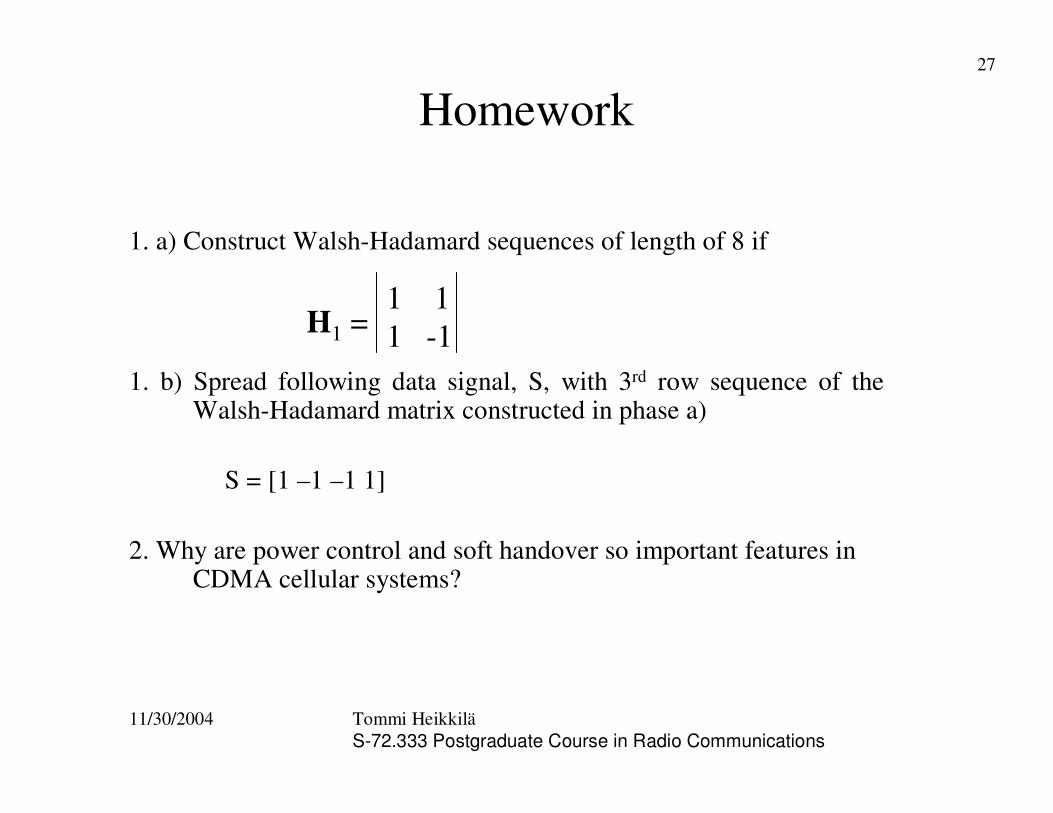
Homework
1. a) Construct Walsh-Hadamard sequences of length of 8 if
1. b) Spread following data signal, S, with 3rd row sequence of the Walsh-Hadamard matrix constructed in phase a)
S = [1 –1 –1 1]
2. Why are power control and soft handover so important features in CDMA cellular systems?
H1 =1 11 -1


![Publication [IV] - TKK](https://static.documents.pub/doc/80x56/61f2fb971a17171fc95f7b67/publication-iv-tkk.jpg)


