ACI 349.1R-91 (Reapproved 2000) supersedes ACI 349.1R-91 (Reapproved 1996) and became effective July 1, 1991. In 1991, a number of minor editorial revisions were made to the report. The year designation of the recommended references of the standards-producing organizations have been removed so that the current editions become the referenced editions. *Prime authors of the thermal effects report. Copyright 2000, American Concrete Institute. All rights reserved including rights of reproduction and use in any form or by any means, including the making of copies by any photo process, or by electronic or mechanical device, printed, written, or oral, or recording for sound or visual reproduc- tion or for use in any knowledge or retrieval system or device, unless permission in writing is obtained from the copyright proprietors. ACI Committee Reports, Guides, Standard Practices, and Commen- taries are intended for guidance in planning, designing, executing, and inspecting construction. This document is intended for the use of indi- viduals who are competent to evaluate the significance and limitations of its content and recommendations and who will accept responsibility for the application of the material it contains. The American Concrete Institute disclaims any and all responsibility for the stated principles. The Institute shall not be liable for any loss or damage arising therefrom. Reference to this document shall not be made in contract documents. If items found in this document are desired by the Architect/Engineer to be a part of the contract documents, they shall be restated in mandatory language for incorporation by the Architect/Engineer. 349.1R-1 Reinforced Concrete Design for Thermal Effects on Nuclear Power Plant Structures ACI 349.1R-91 (Reapproved 2000) This report presents a design-oriented approach for considering thermal loads on reinforced concrete structures. A simplified method is provided for estimating reduced thermal moments resulting from cracking of concrete sections. The method is not applicable to shear walls or for determining axial forces resulting from thermal restraints. The global effects of temper- ature, such as expansion, contraction, and thermal restraints are not spe- cifically addressed. However, they need to be considered as required by Appendix A of ACI 349. Although the approach is intended to conform to the general provisions of Appendix A of ACI 349, it is not restricted to nuclear power plant structures. Two types of structures, frames, and axi- symmetric shells, are addressed. For frame structures, a rationale is described for determining the extent of member cracking, which can be assumed for purposes of obtaining the cracked structure thermal forces and moments. Stiffness coefficients and carryover factors are presented in graphical form as a function of the extent of member cracking along its length and the reinforcement ratio. Fixed-end thermal moments for cracked members are expressed in terms of these factors for: 1) a temperature gra- dient across the depth of the member; and 2) end displacements due to a uniform temperature change along the axes of adjacent members. For the axisymmetric shells, normalized cracked section thermal moments are pre- sented in graphical form. These moments are normalized with respect to the cross section dimensions and the temperature gradient across the sec- tion. The normalized moments are presented as a function of the internal axial forces and moments acting on the section and the reinforcement ratio. Use of the graphical information is illustrated by examples. Keywords: cracking (fracturing); frames; nuclear power plants; reinforced concrete; shells (structural forms); structural analysis; structural design; temperature; thermal gradient; thermal properties; thermal stresses. CONTENTS Notation, p. 349.1R-1 Chapter 1—Introduction, p. 349.1R-2 Chapter 2—Frame structures, p. 349.1R-3 2.1—Scope 2.2—Section cracking 2.3—Member cracking 2.4—Cracked member fixed-end moments, stiffness fac- tors, and carryover factors 2.5—Frame design example Chapter 3—Axisymmetric structures, p. 349.1R-17 3.1—Scope 3.2—|e/d| ≥ 0.7 for compressive N and tensile M 3.3—General e/d 3.4—Design examples Chapter 4—References, p. 349.1R-29 4.1—Recommended references 4.2—Cited references NOTATION General A s = area of tension reinforcement within width b A s ¢ = area of compression reinforcement within width b b = width of rectangular cross section d = distance from extreme fiber of compression face to centroid of compression reinforcement d ¢ = distance from extreme fiber of compression face to centroid of tension reinforcement e = eccentricity of internal force N on the rectangular section, measured from the section centerline E c = modulus of elasticity of concrete E s = modulus of elasticity of reinforcing steel f c ¢ = specified compressive strength of concrete f y = specified yield strength of reinforcing steel j = ratio of the distance between the centroid of com- pression and centroid of tension reinforcement to the depth d n = modular ratio = E s /E c t = thickness of rectangular section T m = mean temperature, F T b = base (stress-free) temperature, F ∆T = linear temperature gradient, F α = concrete coefficient of thermal expansion, in./in./F ν = Poisson’s ratio of concrete = ratio of tension reinforcement = A s /bd = ratio of compression reinforcement = A s ¢ /bd Chapter 2—Frame structures a = length of the cracked end of member at which the stiffness coefficient and carry- Reported by ACI Committee 349 For a list of Committee members, see p. 30.
Transcript
Reinforced Concrete Design for Thermal Effectson Nuclear Power Plant Structures
ACI 349.1R-91(Reapproved 2000)
This report presents a design-oriented approach for considering thermalloads on reinforced concrete structures. A simplified method is provided forestimating reduced thermal moments resulting from cracking of concretesections. The method is not applicable to shear walls or for determiningaxial forces resulting from thermal restraints. The global effects of temper-ature, such as expansion, contraction, and thermal restraints are not spe-cifically addressed. However, they need to be considered as required byAppendix A of ACI 349. Although the approach is intended to conform tothe general provisions of Appendix A of ACI 349, it is not restricted tonuclear power plant structures. Two types of structures, frames, and axi-symmetric shells, are addressed. For frame structures, a rationale isdescribed for determining the extent of member cracking, which can beassumed for purposes of obtaining the cracked structure thermal forcesand moments. Stiffness coefficients and carryover factors are presented ingraphical form as a function of the extent of member cracking along itslength and the reinforcement ratio. Fixed-end thermal moments for crackedmembers are expressed in terms of these factors for: 1) a temperature gra-dient across the depth of the member; and 2) end displacements due to auniform temperature change along the axes of adjacent members. For theaxisymmetric shells, normalized cracked section thermal moments are pre-sented in graphical form. These moments are normalized with respect tothe cross section dimensions and the temperature gradient across the sec-tion. The normalized moments are presented as a function of the internalaxial forces and moments acting on the section and the reinforcement ratio.
C
C
GAAbd
d
e
EEffj
ntTT∆αν
Chapter 2—Frame structuresa = length of the cracked end of member at
which the stiffness coefficient and carry-
Reported by ACI Committee 349For a list of Committee members, see p. 30.
ACI Committee Reports, Guides, Standard Practices, and Commen-
Use of the graphical information is illustrated by examples.
Chapter 2—Frame structures, p. 349.1R-32.1—Scope2.2—Section cracking2.3—Member cracking2.4—Cracked member fixed-end moments, stiffness fac-
tors, and carryover factors
awsb*
mmtiw
taries are intended for guidance in planning, designing, executing, andinspecting construction. This document is intended for the use of indi-viduals who are competent to evaluate the significance and limitationsof its content and recommendations and who will accept responsibilityfor the application of the material it contains. The American ConcreteInstitute disclaims any and all responsibility for the stated principles.The Institute shall not be liable for any loss or damage arising therefrom.
Reference to this document shall not be made in contract documents.If items found in this document are desired by the Architect/Engineer tobe a part of the contract documents, they shall be restated in mandatorylanguage for incorporation by the Architect/Engineer.
349.1R-1
2.5—Frame design example
hapter 3—Axisymmetric structures, p. 349.1R-173.1—Scope3.2—|e/d| ≥ 0.7 for compressive N and tensile M3.3—General e/d3.4—Design examples
hapter 4—References, p. 349.1R-294.1—Recommended references4.2—Cited references
NOTATIONenerals = area of tension reinforcement within width bs′ = area of compression reinforcement within width b
= width of rectangular cross section= distance from extreme fiber of compression face to
centroid of compression reinforcement′ = distance from extreme fiber of compression face to
centroid of tension reinforcement= eccentricity of internal force N on the rectangular
section, measured from the section centerlinec = modulus of elasticity of concretes = modulus of elasticity of reinforcing steel
c′ = specified compressive strength of concretey = specified yield strength of reinforcing steel
= ratio of the distance between the centroid of com-pression and centroid of tension reinforcement tothe depth d
= modular ratio = Es /Ec= thickness of rectangular section
m = mean temperature, Fb = base (stress-free) temperature, FT = linear temperature gradient, F
= concrete coefficient of thermal expansion, in./in./F= Poisson’s ratio of concrete= ratio of tension reinforcement = As /bd= ratio of compression reinforcement = As′ /bd
ACI 349.1R-91 (Reapproved 2000) supersedes ACI 349.1R-91 (Reapproved 1996)nd became effective July 1, 1991. In 1991, a number of minor editorial revisionsere made to the report. The year designation of the recommended references of the
tandards-producing organizations have been removed so that the current editionsecome the referenced editions.Prime authors of the thermal effects report.Copyright 2000, American Concrete Institute.All rights reserved including rights of reproduction and use in any form or by anyeans, including the making of copies by any photo process, or by electronic orechanical device, printed, written, or oral, or recording for sound or visual reproduc-on or for use in any knowledge or retrieval system or device, unless permission inriting is obtained from the copyright proprietors.
=
=
=
==
=
=
=
=
=
=
====
=
=
=
over factor are determined, in the case ofan end-cracked beam (Fig. 2.4 through2.7). In the case of an interior-crackedbeam, (Fig. 2.8 through 2.1l), a is thelength of the uncracked end of member atwhich the stiffness coefficient and carry-over factor are determined.cracked member carry-over factor fromEnd A to End Bcracked member carry-over factor fromEnd B to End Acracked member carry-over factor from thea end of the member to the opposite endmodulus of rupture of concretecracked section moment of inertia aboutthe centroid of the cracked rectangular sec-tionuncracked section moment of inertia (ex-cluding reinforcement) about the centerline of the rectangular sectionratio of depth of the triangular com-pressive stress block to the depth dcracked member stiffness at End A(pinned), with opposite end fixedcracked member stiffness at End B(pinned), with opposite end fixedcracked member stiffness at End a(pinned), with opposite end fixeddimensionless stiffness coefficient= KL/EcIgtotal length of membercracked length of membercracking moment = bt2fr/6cracked member fixed-end moment due to_̂ T or Tm - Tb, at End amoment at center line of rectangular crosssectionaxial force at center line of rectangularcross sectiontransverse displacement difference betweenends of cracked member, due to Tm - Tbacting on adjoining members
Chapter 3 - Axisymmetric structures
fc =
fCL =
k =
kL =
final cracked section extreme fiber com-pressive stress resulting from internal sec-tion forces M, N, and _̂ Tcracked section extreme fiber compressivestress resulting from internal forces Mand Nratio of depth ofpressive stress blocksulting from internaland _̂ Tratio of depth ofpressive stress blocksulting from internalN
the triangular com-to the depth d, re-section forces M, N,
the triangular com-to the depth d, re-section forces M and
M =
N =
iv =
M,r =6, =
LCL =
ECT =
4,. =
4T =
4 =
internal moment at section center line dueto factored mechanical loads, includingfactored moment due to Tm - Tbinternal axial force at section center linedue to factored mechanical loads, includingfactored axial force due to Tm - Tbfinal internal moment at section center lineresulting from M and _̂ Tthermal moment due to _̂ T, M,= = A?f - Mfinal cracked section strain at extreme fiberof compression face = &cL + &Tcracked section strain at extreme fiber ofcompression face resulting from internalsection forces M and Ncracked section strain at extreme fiber ofcompression face resulting from _̂ Tcracked section curvature change resultingfrom internal forces M and Ncracked section curvature change requiredto return free thermal curvature aAT/t to 0final cracked section curvature change =+1. + 4r
CHAPTER 1--INTRODUCTIONACI 349, Appendix A, provides general consid-
erations in designing reinforced concrete structures fornuclear power plants. The Commentary to AppendixA, Section A.3.3, addresses three approaches thatconsider thermal loads in conjunction with all othernonthermal loads on the structure, termed “mechani-cal loads.” One approach is to consider the structureuncracked under the mechanical loads and crackedunder the thermal loads. The results of two such anal-yses are combined.
The Commentary to Appendix A also contains amethod of treating temperature distributions across acracked section. In this method an equivalent lineartemperature distribution is obtained from the temper-ature distribution, which can generally be nonlinear.Then the linear temperature distribution is separatedinto a pure gradient _̂ T and into the difference be-tween the mean and base (stress-free) temperaturesTm - Tb .
This report offers a specific approach for consid-ering thermal load effects which is consistent with theabove provisions. The aim herein is to present a de-signer-oriented approach for determining the reducedthermal moments which result from cracking of theconcrete structure. Chapter 2 addresses frame struc-tures, and Chapter 3 deals with axisymmetric struc-tures. For frame structures, the general criteria aregiven in Sections 2.2 (Section Cracking) and 2.3(Member Cracking). The criteria are then formulatedfor the moment distribution method of structuralanalysis in Section 2.4. Cracked member fixed-endmoments, stiffness coefficients, and carry-over fac-tors are derived and presented in graphical form. Foraxisymmetric structures an approach is described forregions away from discontinuities, and graphs ofcracked section thermal moments are presented.
DESlGN FOR THERMAL EFFECTS/NUCLEAR PLANTS 349.1R-3
This report is not intended to represent a state-of-the-art discussion of the methods available to analyzestructures for thermal loads. Rather, the report is in-tended to propose simplifications that can be madewhich will permit a cracking reduction of thermal mo-ments to be readily achieved for a large class of ther-mal loads, without resorting to sophisticated and com-plex solutions. Also, as a result of the reportdiscussion, the design examples, and graphical presen-tation of cracked section thermal moments, it ishoped that a designer will better understand how ther-mal moments are affected by the presence of otherloads and the resulting concrete cracking.
CHAPTER 2 - FRAME STRUCTURES2.1 - Scope
The thermal load on the frame is assumed to berepresented by temperatures which vary linearlythrough the thicknesses of the members. The lineartemperature distribution for a specific member mustbe constant along its length. Each such distributioncan be separated into a gradient _̂ T and into a tem-perature change with respect to a base (stress-free)temperature Tm - Tb.
Frame structures are characterized by their abilityto undergo significant flexural deformation underthese thermal loads. They are distinguished from theaxisymmetric structures discussed in Chapter 3 by theability of their structural members to undergo rota-tion, such that the free thermal curvature change ofaAT/f is not completely restrained. The thermal mo-ments in the members are proportional to the degreeof restraint. In addition to frames per se, slabs andwalls may fall into this category.
The rotational feature above is of course automati-cally considered in a structural analysis using un-cracked member properties. However, an additionalreduction of the member thermal moments can occurif member cracking is taken into account. Sections 2.2and 2.3 of this chapter describe criteria for the crack-ing reduction of member thermal moments. These cri-teria can be used as the basis for an analysis of thestructure under thermal loads, regardless of themethod of analysis selected. In Section 2.4, these cri-teria are applied to the moment distribution analysismethod.
There are frame and slab structures which can beadequately idealized as frames of sufficient geometricsimplicity to lend themselves to moment distribution.Even if an entire frame or slab structure does not per-mit a simple idealization, substructures can be isolatedto study the effects of thermal loads. Often withtoday’s use of large scale computer programs for theanalysis of complex structures, a “feel” for the rea-sonableness of the results is attainable only throughless complex analyses applied to substructures. Themoment distribution method for thermal loads is ap-plicable for this work. This design approach usescracked member stiffness coefficients and carry-over
factors. These depend on the extent of member crack-ing along its length due to mechanical loads, as dis-cussed in Section 2.3.
2.2 - Section crackingSimplifying assumptions are made below for the
purpose of obtaining the cracked section thermal mo-ments and the section (cracked and uncracked) stiff-nesses. The fixed-end moments, stiffness coefficients,and carry-over factors of Section 2.4 are based onthese assumptions:
1. Concrete compression stress is taken to be lin-early proportional to strain over the member crosssection.
2. For an uncracked section, the moment of inertiais Ig, where Ig is based on the gross concrete dimen-sions and the reinforcement is excluded.
For a cracked section, the moment of inertia is Icr,where Icr is referenced to the centroidal axis of thecracked section. In the formulation of Icr, the com-pression reinforcement is excluded and the tension re-inforcement is taken to be located at the tension face;i.e., d = t is used.
3. The axial force on the section due to mechanicaland thermal loads is assumed to be small relative tothe moment (e/d >, 0.5). Consequently, the extent ofsection cracking is taken as that which occurs for apure moment acting on the section.
The first assumption is strictly valid only if the ex-treme fiber concrete compressive stress due to com-bined mechanical and thermal loads does not exceed0.5f'c. At this stress, the corresponding concrete strainis in the neighborhood of 0.0005 in./in. For extremefiber concrete compressive strains greater than 0.0005in./in. but less than 0.001 in./in., the differences areinsignificant between a cracked section thermal mo-ment based on the linear assumption adopted hereinversus a nonlinear concrete stress-strain relationshipsuch as that described in References 2 and 3. Con-sequently, cracked member thermal moments given byEq. (2-3) and (2-4) are sufficiently accurate for con-crete strains not exceeding 0.001 in./in.
For concrete strains greater than 0.001 in./in., theequations identified above will result in cracked mem-ber thermal moments which are greater than thosebased on the nonlinear theory. In this regard, thethermal moments are conservative. However, they arestill reduced from their uncracked values. This crack-ing reduction of thermal moments can be substantial,as seen in Fig. 3.2 which also incorporates Assump-tion 1.
Formulation of the thermal moments based on alinear concrete stress-strain relationship allows thethermal moments to be expressed simply by the equa-tions in Chapter 2 or by the normalized thermal mo-ment graphs of Chapter 3. Such simplicity is desirablein a designer-oriented approach.
Regarding Icr, in Assumption 2, the assumptions forthe compression and tension reinforcement result inthe simple expression of (6jk2)Ig for Icr, if the axial
load is small as specified in Assumption 3. The use of(6jk2)Ig will overestimate the cracked section momentof inertia of sections, for which e/d >, 0.5, either withor without compression reinforcement. For a memberwith only tension reinforcement typically located at d= 0.90t, the actual cracked section moment of inertiais overestimated by 35 percent, regardless of theamount of reinforcement. For a member with equalamounts of compression and tension reinforcement,located at d’ = 0.1d and d = 0.9t, its actual crackedsection moment of inertia is also overestimated. Theoverestimation will vary from 35 percent at the lowerreinforcement ratio (Q ‘n = Qn = 0.02) down to 15percent at the higher values (Q ‘n = gn = 0.12).
The use of (6jk2)Ig for cracked sections and theuse of Ig for uncracked sections are further discussedrelative to member cracking in Section 2.3.
Regarding the third assumption, the magnitude ofthe thermal moment depends on the extent of sectioncracking as reflected by Icr. Icr depends on the axialforce N and moment M. The relationship of Icr/Ig ver-sus e/d, where e = M/N, is shown in Fig. 2.1. The
eccentricity e is referred to the section center line. InFig. 2.1 it is seen that for e/d 3 1, Icr is practicallythe same as that corresponding to pure bending. Fore/d 2 0.5, the associated Icr is within 10 percent of itspure bending value. Most nonprestressed frame prob-lems are in the e/d Z 0.5 category. Consequently, forthese problems it is accurate within 10 percent to usethe pure bending value of (6jk2)Ig for Icr. This is thebasis of Assumption 3.
2.3 - Member crackingIdeally, a sophisticated analysis of a frame or slab
structure subjected to both mechanical and thermalloads might consider concrete cracking and the re-sulting changes in member properties at many stagesof the load application. Such an analysis would con-sider the sequential application of the loads, andcracking would be based on the modulus of ruptureof the concrete fr . The loads would be applied in-crementally to the structure. After each load in-crement, the section properties would be revised forthose portions of the members which exhibit extremefiber tensile stresses in excess of fr. The properties ofthe members for a given load increment would reflectthe member cracking that had occurred under the sumof all preceding load increments. In such an analysis,the thermal moments would be a result of membercracking occurring not only for mechanical loads, butalso for thermal loads.
The type of analysis summarized above is consistentwith the approach in Item 2 of Section A.3.3 of theCommentary to Appendix A. An approximate analy-sis, but one which is generally conservative for thethermal loads, is suggested in Item 3 of Section A.3.3as an alternative. This alternate analysis considers thestructure to be uncracked under the mechanical loadsand to be cracked under the thermal loads. The re-sults of an analysis of the uncracked structure under
mechanical loads are combined with the results of ananalysis of the cracked structure under the thermalloads. A simplified method of analysis is discussed be-low which will yield cracked member thermal mo-ments that are conservative for most practical prob-lems.
The extent of cracking which the members expe-rience under the total mechanical load (including thespecified load factors) forms the basis for the crackedstructure used for the thermal load analysis. Crackingwill occur wherever the mechanical load moments ex-ceed the cracking moment Mcr. The addition of ther-mal moments which are the same sign as mechanicalmoments will increase the extent of cracking along themember length. Recognizing this, in many cases it isconservative for design to consider the member to becracked wherever tensile stresses are produced by themechanical loads if these stresses would be increasedby the thermal loads. Any increase in the crackedlength due to the addition of the thermal loads is con-servatively ignored, and an iterative solution is not re-quired. However, the addition of thermal momentswhich are of opposite sign to the mechanical momentsthat exceed Mcr may result in a final section which isuncracked. Therefore, for simplicity, the member isconsidered to be uncracked for the thermal load anal-ysis wherever along its length the mechanical momentsand thermal moments are of opposite sign.
Two types of cracked members will result: (1) end-cracked, and (2) interior-cracked. The first type oc-curs for cases where mechanical and thermal momentsare of like sign at the member ends. The second typeoccurs where these moments are of like sign at the in-terior of the member. Stiffness coefficients, carry-overfactors, and fixed-end thermal moments are developedfor these two types of members in Section 2.4. Acomprehensive design example is presented in Section2.5.
The above simplification of considering the memberto be uncracked wherever the mechanical and thermalmoments are of opposite sign is conservative due tothe fact that the initial portion of a thermal load,such as _̂ T, will actually act on a section which maybe cracked under the mechanical loads. Consequently,the fixed-end moment due to this part of _̂ T will bethat due to a member completely cracked along itslength. Once the cracks close, the balance of _̂ T willact on an uncracked section. Consideration of thistwo-phase aspect makes the problem more complex.The conservative approach adopted herein removesthis complexity. However, some of the conservatism isreduced by the use of Ig for the uncracked section(Assumption 2) rather than its actual uncracked sec-tion stiffness, which would include reinforcement andis substantially greater than Ig for Qn 2 0.06.
The fixed-end moments depend not only on thecracked length LT but also on the location of thecracked length a along the member. This can be seenfrom a comparison of the results for an end-crackedmember and an interior-cracked member for the same
DESIGN FOR THERMAL EFFECTS/NUCLEAR PLANTS 349.1R-5
0.8
0.7
0.6
Fb
0‘a-t
4 0.5%zEs5.-ts:
0.4
iic50
-r,
f 0.3
(5-00._
6aL
0.2
0.1
llllllllllliltIll III I III III
For e/d + 00,
I I
1 _____. t Icr, --= 6jk2I kl
00 0.02 0.04 0.06 0.08 0.10 0.12
Tension Reinforcement, pn
Fig. 2. 1 - Effect of axial force on cracked section moment of inertia (No compression reinforcement)
349.1 R-6 ACI COMMITTEE REPORT
value of Lr. The method discussed in Section 2.4 ac-counts for this. This approach is more applicable forthe determination of the thermal moments than theuse of an effective moment of inertia for the entiremember length. The concept of a single effective mo-ment of inertia for purposes of member deflection cal-culation has resulted in Eq. (9-4) of ACI 349-76. Thisequation is empirically based and, as such, accountsfor (1) partially cracked sections along the member,and (2) the existence of uncracked sections occurringbetween flexural cracks. These two characteristics areindirectly provided for (to an unknown extent) by theuse of (6jk2)1,, which overestimates the cracked sec-tion moment of inertia by the amount described pre-viously.
2.4 - Cracked member fixed-end moments,stiffness coefficients, and carry-over factors
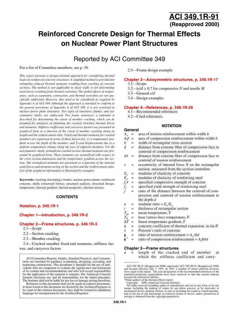
The thermal moments due to the linear temperaturegradient /_\ \ T, and those resulting from the expansionor contraction of the axis of the member T,,, - Tb, areconsidered separately. For each type of thermal load,fixed-end moments, stiffness coefficients, and carry-over factors were obtained for two types of crackedmembers: (1) end-cracked, and (2) interior-cracked.The first type applies for cases where mechanical andthermal loads produce moments of like sign at mem-ber ends. The second type applies for cases where me-chanical and thermal loads produce moments of likesign in the interior of the member.
These factors are presented for the case of an end-cracked member in Fig. 2.2.
MA
LT-a 1
I
L - LT
I
I; a
C- -1
Fig. 2.2 - /_\ T fixed-end moments - Member crackedat ends by mechanical loads
h4* =
(2-1)
M, =
Although shown only for a member cracked at theends, the above expressions for MA and MR also ap-ply to a member cracked in its interior.
In the above:aATL/2t =
K.4 =
KS =
co,, =
co,, =
the angle change of the memberends with the rotational restraintsremovedthe stiffness of the member at Awith B fixed (4EJ,/L for uncrackedmember)the stiffness of the member at Bwith A fixed (4EJ,/‘L for the un-cracked member)the carry-over factor from A to B(‘/z for uncracked member)the carry-over factor from B to A(‘/z for uncracked member)
The expressions for K and CO can be derived frommoment-area principles. Also, K can be expressed as:
K = -E+ k, (2-2)
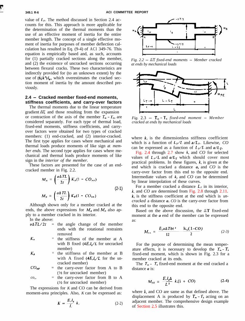
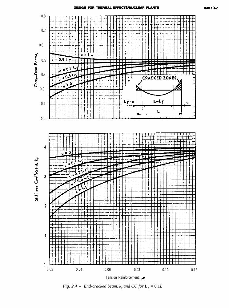
where k, is the dimensionless stiffness coefficientwhich is a function of LJL and a/LT. Likewise, COcan be expressed as a function of LJL and a/LT.
Fig. 2.4 through 2.7 show k, and CO for selected
values of LJL and a/LT which should cover mostpractical problems. In these figures, k, is given at theend which is cracked a distance a, and CO is thecarry-over factor from this end to the opposite end.Intermediate values of k, and CO can be determinedby linear interpolation of these curves.
For a member cracked a distance Lr in its interior,k, and CO are determined from Fig. 2.8 through 2.11.
k, is the stiffness coefficient at the end which is un-cracked a distance a. CO is the carry-over factor fromthis end to the opposite end.
Based on the above discussion, the /_\ T fixed-endmoment at the a end of the member can be expressedas:
MFE =_ks(1-CO)
2 (2-3)12
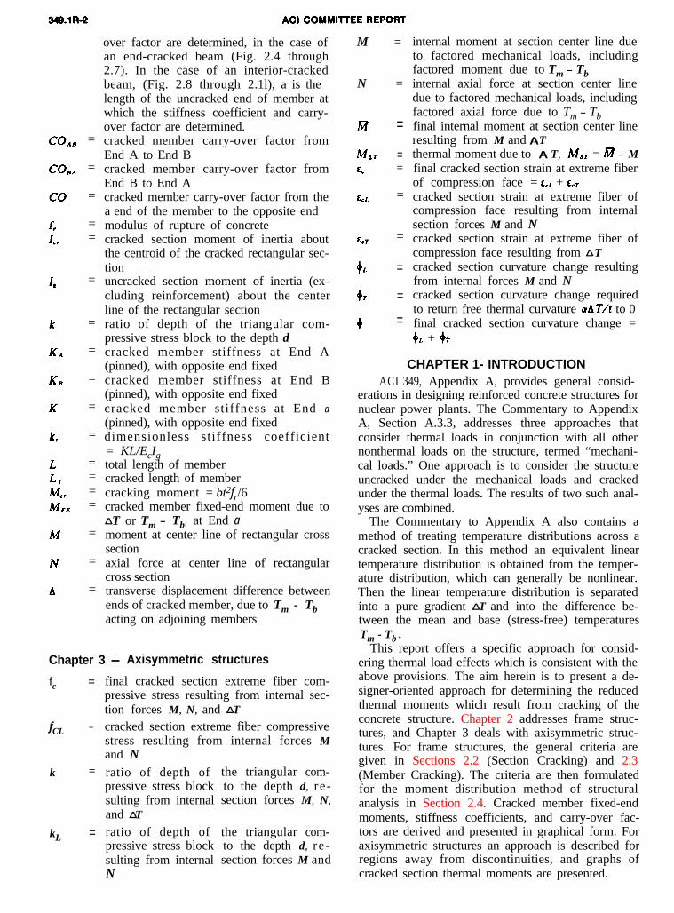
For the purpose of determining the mean temper-ature effects, it is necessary to develop the T, - Tbfixed-end moment, which is shown in Fig. 2.3 for a
.I - ,
Fig. 2.3 - T, - T, fixed-end moment - Membercracked at ends by mechanical loads
member cracked at its ends.The T,,, - Tb fixed-end moment at the end cracked a
distance a is:
M,. =E&AL2 k(l + CO)
where k, and CO are same as that defined above. Thedisplacement A is produced by T,,, - Tb acting on anadjacent member. The comprehensive design exampleof Section 2.5 illustrates this.
0.8
0.7
0.6
$"0 0.5IL
P9 0.4
:" 0.3
0.2
0.1
0
t- i i i 1-t i i i j ILF? d-i!i ?-+- 'd
0.02 0.04 0.06 0.08 0.10 0.12
Tension Reinforcement, pn
Fig. 2.4 - End-cracked beam, ks and CO for LT = 0.1L
0.8
0.7
0.6
gi 0.5IL
Ey 0.4
s
” 0.3
0.2
0.1
0.02 0.04 0.06 0.08 0.10 0.12
Tension Reinforcement, pn
Fig. 2.5 - End-cracked beam, ks and CO for LT= 0.2L
0.8
8 0.7
5g 0.6
LL
50 0.5
2.bv
0.4
0.3
0.2
FEFI CRACKED ZONES,
i i I ! I I
0.02 0.04 0.06 0.08 0.10 0.1
Tension Reinforcement, pn
Fig.2.4 - End-cracked beam, ks and CO for LT =
1.0
0.9
0.8
0.7
0.6
0.5
0.4
0.3
0.2
0.1
00.02 0.04 0.06 0.08 0.10 0.12
Tension Reinforcement, pn
Fig. 2.7 - End-cracked beam, ks and CO for LT = 0.6L
0.8
0.7
80.6
.
p 0.5
tttHtt i i i i i tttth
rt+i--t I III. I I 1IIIIIIhl. 1”“’I I I 1 I
0.02 0.04 0.06 0.08 0.10 0.12
Tension Reinforcement, pn
Fig. 2.8 - Interior-cracked beam, ks and CO for LT = 0.1L
349.1R-12
1.0
0.9
0.8
0.7
gg 0.6
IL
E9 0.5
f6
v 0.4
0.3
0.2
0.1
0.02 0.04 0.06 0.08 0.10 0.12
Tension Reinforcement, pn
Fig. 2.9 - Interior-cracked beam, ks and CO for LT = 0.2L
349.1R--13
0.9
0.8
s0.7
.5t 0.6lEii
& 0.5
k&” 0.4
0.3
0.2
0.1
+-i-i--c ! ! : f 4 f f : ! ! !
00.02 0.04 0.06 0.08 0.10 0.12
Tension Reinforcement, pn
Fig. 2.10 - Inferior-cracked beam, ks and CO for LT = 0.4L
0.8
s 0.7
L‘eIE
0.6
Fy 0.5L.'0
"0.4
0.3
0.2
0.1
3
Al?.5._U._r0s 2
s:0c-._s
1
0
:I 1. I I I i 1 II 11 I I ill1 I I! Iu’lll, llllllllllllllll~
0.02 0.04 0.06 0.08 0.10 0.12
Tension Reinforcement, p
Fig. 2.11- Interior-cracked beam, ks and CO for LT = 0.6L
DESIGN FOR THERMAL EFFECTS/NUCLEAR PLANTS 349.1R-15
2.5 - Frame design exampleGiven the continuous frame shown in Fig. 2.12 with
TOUTS~DE = SOOF 137.4
W D + L = 1086 LB/FT
--- M E C H A N I C A L L O A D S
- M E C H A N I C A L A N D T H E R M A L
l _̂ T = &lOoF, T, - Tb = WF, UNCRACKED FRAME
Fig. 2.12 - Uncracked frame moments (ft-kips)
all members 1 ft wide x 2 ft thick and 3-in. cover onthe reinforcement. The load combination to be con-sidered is U = D + L+ To + Ess.
The mechanical loading consists of:
WD = 406 lb/ftWL
= 680 lb/ft
on member BC and a lateral load of 3750 lb at JointC due to Ess.
The thermal loading To consists of 130 F interiorand 50 F exterior on all members. The base temper-ature Tb is taken as 70 F. For this condition, Tm - Tb= + 20 F and _̂ T = 80 F (hot interior, cold exterior).
The material properties are f,’ = 3000 psi and Ec =3.12 x 10⁶ psi; fy = 60,000 psi and Es = 29 x 106 psi;and o( = 5 x 10⁻⁶ in./in./deg F. Also, n = Es/Ec =9.3.
The reinforcement in the frame consists of 2-#8bars at each face in all members. This results in Q =1.58/(12 x 21) = 0.0063 and qn = 9.3 (0.0063) =0.059. The section capacity is Mu = KuF = (320)x (12)(21)2/12,000 = 141.1 ft-kips.
Mechanical loads
An analysis of the uncracked frame results in themember moments (ft-kips) below. Moments actingcounterclockwise on a member are denoted as posi-tive. These values were obtained by moment distribu-tion, and moments due to Ess include the effect offrame sidesway.
AB: -52.3BA: -76.0B C : +76.0CB: -46.0C D : +46.0D C : +7.5
These are shown in Fig. 2.12.The maximum mechanical load moment of 76 ft-
kips is less than the section capacity of 141.1 ft-kips.Therefore, the frame is adequate for mechanicalloads.
Thermal loads (_̂ T = 80 F and Tm - Tb = 20 F)
The _̂ T = 80 F having hot interior and cold exte-rior is expected to produce thermal stresses which aretensile on the exterior faces of all members. Thesestresses will add to the existing exterior face tensilestresses due to the mechanical loads. Hence, the LTand a values are arrived at from the mechanical loadmoment diagram in Fig. 2.12.
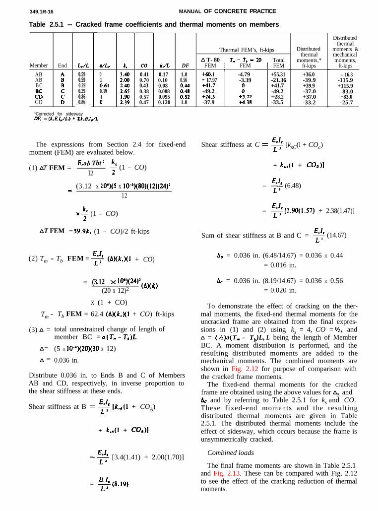
The expressions from Section 2.4 for fixed-endmoment (FEM) are evaluated below.
(1) _̂ T FEM =E,aA Tbt 2 ks
l2j- (1 - CO)
_ (3.12 x 10*)(5 x 10-“)(80)(12)(24)212
x+ (1 - CO)
_̂ T FEM = 59.9k, (1 - CO)/2 ft-kips
(2) Tm - Tb FEM = $+ (A)&)(1 + CO)
= (3.12 x io6)(24)3 (b)(k )
(20 x 12)2 s
x (1 + CO)
Tm - Tb FEM = 62.4 (A)(k,)(l + CO) ft-kips
(3) _̂ =
_̂ =_̂ =
total unrestrained change of length ofmember BC = a(T,,, - T,)L
(5 x 10⁻⁶)(20)(30 x 12)
0.036 in.
Distribute 0.036 in. to Ends B and C of MembersAB and CD, respectively, in inverse proportion tothe shear stiffness at these ends.
Shear stiffness at B = $+ [k&l + COA)
+ ks,(l + COdI
=- $ [3.4(1.41) + 2.00(1.70)]
= s(8.19)
Shear stiffness at C =s [ksC(l + COc)
+ k,D(l + CWI
= $ (6.48)
= $+0(1.57) + 2.38(1.47)]
Sum of shear stiffness at B and C = ++ (14.67)
Ag = 0.036 in. (6.48/14.67) = 0.036 x 0.44= 0.016 in.
AC = 0.036 in. (8.19/14.67) = 0.036 x 0.56= 0.020 in.
To demonstrate the effect of cracking on the ther-mal moments, the fixed-end thermal moments for theuncracked frame are obtained from the final expres-sions in (1) and (2) using ks = 4, CO = 1/2, and_̂ = (%)o(T, - Tb)L, L being the length of MemberBC. A moment distribution is performed, and theresulting distributed moments are added to themechanical moments. The combined moments areshown in Fig. 2.12 for purpose of comparison withthe cracked frame moments.
The fixed-end thermal moments for the crackedframe are obtained using the above values for _̂ B andAC and by referring to Table 2.5.1 for ks and CO.These fixed-end moments and the resultingdistributed thermal moments are given in Table2.5.1. The distributed thermal moments include theeffect of sidesway, which occurs because the frame isunsymmetrically cracked.
Combined loads
The final frame moments are shown in Table 2.5.1and Fig. 2.13. These can be compared with Fig. 2.12to see the effect of the cracking reduction of thermalmoments.
b
\
61.6
\b\
16.3 52.3 25.7
---M E C H A N I C A L (UNCRACKED F R A M E )
MECHANICAL AND THERMAL*
l _̂ T = 8 0 o F , Tm - Tb, = 20oF, CRACKED FRAME
Fig. 2.13 - Final frame moments (ft-kips)
Although not shown, the member axial forces wereevaluated to confirm that section cracking still cor-responds to the pure bending condition of Assump-tion 3. Recall that e/d must be at least 0.5 for thiscondition. For Members AB and CD, the axial forcesresult primarily from the mechanical loads and arecompressive. For Member BC, the axial force is com-pressive and includes the compression due to the20 F increase on the member.
CHAPTER 3 - AXISYMMETRIC STRUCTURES
3.1 - Scope
Axisymmetric structures include shells of revolutionsuch as shield buildings or, depending on the particu-lar geometry, primary and secondary shield walls. Inthe structural analysis, the structure is considered tobe uncracked for all mechanical loads and for part ofthe thermal loads. The thermal load is assumed to berepresented by a temperature which is distributed lin-early through the wall of the structure. The lineartemperature distribution is separated into a gradient ATand into a uniform temperature change Tm - Tb.
Generally, for most axisymmetric structures, a uni-form temperature change (Tm - Tb) produces signifi-cant internal section forces (moment included) only atthe externally restrained boundaries of the structurewhere free thermal growth is prevented, or in regionswhere Tm - Tb varies fairly rapidly along the struc-ture. The magnitude and extent of these discontinuityforces depend on the specific geometry of the structureand on the external restraint provided. If cracking oc-
curs in this region, a prediction of the cracking reduc-tion of the discontinuity forces is attainable through are-analysis using cracked section structural properties.A discussion of such an analysis is not within thescope of the present report. Therefore, forces re-sulting from an analysis for the Tm - Tb part of thethermal load are considered to be included with corre-sponding factored mechanical forces. These combinedaxial forces and moments are denoted as N and M.
The gradient _̂ T produces internal section forces(moment included) at externally restrained boundariesand, also, away from these discontinuities. At dis-continuities, the most significant internal force is usu-ally the moment, primarily resulting from the internalrestraint rather than the external boundary restraint.Away from discontinuities, the only significant forcesdue to _̂ T are thermal moments caused by the internalrestraint provided by the axisymmetric geometry ofthe structure. The cracking reduction of thermal mo-ments which result from internal restraint is the sub-ject of this chapter.
Due to the axisymmetric geometry of the subjectstructures, the free thermal curvature change aAT/t isfully restrained. This restraint produces a correspond-ing thermal moment whose magnitude depends on theextent of cracking the section experiences. This in turndepends on _̂ T, the other section forces N and M, andthe section properties. With the ratio M/N denoted ase, referenced to the section center line, and the dis-tance from the concrete compression face to the ten-sion reinforcement denoted as d, two cases of e/d areidentified in Sections 3.2 and 3.3.
349.1R-18 MANUAL OF CONCRETE PRACTICE
The results in Sections 3.2 and 3.3 include the effectof compression reinforcement. For this reinforcement,a modular ratio of 2n is used for purposes of sim-plifying the determination of the cracked section ther-mal moment. Although not all the loads which com-prise the section forces N and M will necessarily belong-term, the selection of 2n for compression re-inforcement is consistent with design practice.
The results in Sections 3.2 and 3.3 are based on alinear stress-strain relationship for the compressiveconcrete. The basis of this assumption was discussedin Section 2.2. From this discussion, the cracked sec-tion thermal moments can be considered to representupper-bound values when compared with those whichwould result from a nonlinear stress-strain concreterelationship. Nevertheless, the thermal momentsherein do offer a reduction from their uncracked val-ues. The extent of this reduction is shown in Fig. 3.2and Fig. 3.4 through 3.9.
3.2 - le/c/l 2 0.7 for compressive N and ten-sile N
For this range of e/d, a parametric study based onthe results of Section 3.3 indicates that the crackedthermal moment MAT is not strongly influenced by theaxial force as expressed by the ratio N/(bdE,aAT’). Apractical range of N/(bdE,aAT) from 0 to 2300 wasused in this study. Therefore, for ranges of e/d andN/bdE,aAT specified herein, MbT can be calculatedfrom the neutral axis location corresponding to N = 0.
The le/dl lower limit of 0.70 is conservative for ten-sile N and higher QII values. Actual le/d lower limitsfor tensile N are given in Fig. 3.3. As long as the ac-
tual le/dl value for tensile N exceeds this lower limitcurve, the thermal moments given in this section areapplicable.
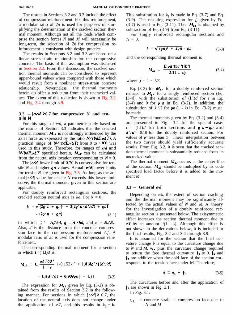
For doubly reinforced rectangular sections, thecracked section neutral axis is kd. For N = 0:
k = v(2q’n + Qn)’ + 2[2Q’n (d//d) + on]
- (2&n + Qn) (3-1)
in which Q' = A,il6d, Q = AJbd, and n = Es/E,.Also, d’ is the distance from the concrete compres-sion face to the compression reinforcement As'. Amodular ratio of 2n is used for the compression rein-forcement.
The corresponding thermal moment for a sectionin which t =( l.l)d is:
aATbd2MAT = E.1 {-0.152k J + 1.818Q’n[(d’/d)
- k](d’/d) + 0.909Qn(l - k)} (3-2)
The expression for M,, given by Eq. (3-2) is ob-tained from the results of Section 3.2 in the follow-ing manner. For sections in which le/dj 2 0.7, thelocation of the neutral axis does not change underthe application of _̂ T, and this results in kL. = k.
This substitution for kL is made in Eq. (3-7) and Eq.(3-9). The resulting expression for fc given by Eq.(3-7) is used in Eq. (3-11). Then Mbf is obtained bysubtraction of Eq. (3-9) from Eq. (3-11).
For singly reinforced rectangular sections andN = 0,
k = \/ (on)’ + 2Qn - Qn
and the corresponding thermal moment is
MbT =E,aA Tbd J(jk ‘)
2t(l - v)
(3-3)
(3-4)
where j = 1 - k/3.
Eq. (3-2) for f&r for a doubly reinforced sectionreduces to Mbf for a singly reinforced section (Eq.[3-4]), with the substitution of (l.l)d for t in Eq.(3-4) and 0 for Q’n in Eq. (3-2). In addition, thesubstitution of k 2/2 for Qn (1 - k) in Eq. (3-2) mustbe made.
The thermal moments given by Eq. (3-2) and (3-4)are presented in Fig. 3.2 for the special case:t = (l.l)d for both sections and g’n = gn andd’/d = 0.10 for the doubly reinforced section. Forvalues of Q’ less than Q, linear interpolation betweenthe two curves should yield sufficiently accurateresults. From Fig. 3.2, it is seen that the cracked sec-tion thermal moment is substantially reduced from itsuncracked value.
The thermal moment Mhr occurs at the center lineof the section. MdT should be multiplied by its codespecified load factor before it is added to the mo-ment M.
3.3 - General e/d
Depending on e/d, the extent of section crackingand the thermal moment may be significantly af-fected by the actual values of N and M. A theoryfor the investigation of a doubly reinforced rec-tangular section is presented below. The axisymmetriceffect increases the section thermal moment due to_̂ T by an amount l/(1 - v). Although this effect isnot shown in the derivations below, it is included inthe final results, Fig. 3.2 and 3.4 through 3.9.
It is assumed for the section that the final cur-vature change 0 is equal to the curvature change dueto N and M, 4,., plus the curvature change requiredto return the free thermal curvature 4T to 0. oL andOr are additive when the cold face of the section cor-responds to the tension face under M. Therefore,
4 = 4L + 4T (3-5)
The curvatures before and after the application4T are shown in Fig. 3.1.
In Fig. 3.1:
EcL = concrete strain at compression face dueN and M
of
to
DESIGN FOR THERMAL EFFECTS/NUCLEAR PLANTS
c
Fig. 3.1 - Section under M, N, _̂ T
LCT =
cc =kLd =
kd =
concrete strain is compression face due to_̂ Ttotal concrete strainneutral axis location on section due to Nand Mneutral axis location on section due to N,M, and _̂ T
The thermal curvature change +T is
97 = aA T/t
where _̂ T is always taken as positive.Using this and cc = +kd and c,,. = +,.kLd in Eq.
(3-5) gives
E,/kd = &k,.d + aAT/t (3-6)
For the case where the concrete stress is a linearfunction of strain, Eq. (3-6) becomes
f,/(E,kd) = f,,./(E,k,.d) + aAT/t
or
f, = (f,,./(E,k,.d) + aAT/t] E,kd (3-7)
To maintain equilibrium of the section both beforeand after the application of _̂ T, the following condi-tions occur:
Before _̂ T1. The internal axial force N is equal to the resul-
tant of the stresses produced by N and M.
N = 1//2f,,.bk,.d + 2~‘nbdf,,[(k,. - d’/d)/k,.]
+ gnbdf,,.[(kL - I)/kLl (3-8)
2. The internal moment M is equal to the internalmoment of the stresses (about the section centerproduced by N and M.
M = ‘/zfCLbk,.d(t/2 - k,.d/3) + 2Q’nbdfCL
x [(kL - d’/d)/kJ [(t/2) - d’] + Qnbdf,,_
x [(1 - k,.)/k,,l[d - (t/2)]
line)
(3-9)
After _̂ T1. The internal axial force N is equal to the resul-
tant of the stresses produced by N, M, and _̂ T.
N = %f,bkd + 2Q’nbdf,[(k - d’/d)/k]
+ Qnbdf,[(k - 1)/k] (3-10)
2. There exists an internal center line moment mof the stresses produced by N, M, and _̂ T.
IW = %f,bkd[(t/2) - (kd/3)] + 2q’nbdf,
x [(k - d’/d)/k] [(t/2) - d’] + Qnbdf,
x [(l - k)/k] [d - (t/2)] (3-l1)
3. The internal thermal moment M,, at the sectioncenter line is equal to M - M.
In Eq. (3-8) through (3-11) the tension and com-pression reinforcement have been expressed asQ = A,/bd and Q’ = A,Ybd, respectively. A modularratio of 2n has been used for the compression rein-forcement. Also, the reinforcement stresses have beenexpressed in terms of the concrete stress.
From Eq. (3-8), fcL can be expressed in terms of N,kL, and the section properties. Use of this inEq. (3-7) allows fc to be written in terms of N, kL,k, E,aAT, and the section properties. Substitution ofthis expression for fc into Eq. (3-10) results in aquadratic equation in k which is solved in terms ofthe section properties, kL, and the quantityN/bdE,aAT. However, by dividing Eq. (3-9) by Eq.(3-8), kL can be written in terms of the section prop-erties and e, where e = M/N. Thus, k is deter-mined for a specified section e and N/bdE,aAT. Theabove results also allow Mdf to be determined fromthese specified quantities.
The equilibrium equations, appearing as Eq. (3-8)through (3-ll), are based on a triangular concretestress distribution. The two extremes of the stressdistribution are at kL = 0.10 and kL = 1.0. Therange 1.0 2 k,. 2 0.10 should cover many practicalsituations not involving prestressed sections. For kL
0.06
f
c’E* 0.04
s5Eerf
0.03
0.02
e = M/Nn = Es/Ec
Uncracked:btr) MAP = 0.101bd’E,cyAT l
(Based on gross concrete section)
0.08 0.10 0.12
Tension Reinforcement, pn
Fig. 3.2 - Cracked section thermal moment for le/d 1 3 0.70
0.80
Pbde = M/N
_ Ic
N (positive as shown)
- .CUseFigures
.A_. . ._L--- . . -3.4 thru 3.9 I. : : 1 I ! : i 1 I I I I III I I II 11’ I I
Iiiiiiiiiiiiiiiiilr i-iiIiTii il;.:iili”’I II P- “““jii:‘iiiiijijiii. .I ! I I
0.06
Reinforcement, pn
Fig. 3.3 - e/d limits
349.1R-22 MANUAL OF CONCRETE PRACTICE
DESIGN FOR THERMAL EFFECTS/NUCLEAR PLANTS
fd
cC
d
‘h M-1)‘lN3WOW lVWkl3Hl
249.1R-24 MANUAL OF CONCRETE PRACTICE
Y3E8
DESIGN FOR THERMAL EFFECTS/NUCLEAR PLANTS
0ci
349.1R-26 MANUAL OF CONCRETE PRACTICE
IVX) ‘3 CPQ
? (n-1)‘INMOW lVVVL13Hl
DESIGN FOR THERMAL EFFECTS/NUCLEAR PLANTS 349.1R-27
s0
‘h &I ‘INMOW lVWL13Hl
349.1R-28 ACI COMMITTEE REPORT
outside this range, i.e., the entire section being undertension ( kL 2 0.10) or compression (kL 2 1.0), a sim-ilar set of equilibrium equations based on a rec-tangular stress distribution would be required.
Special Case:
Q’ = Q, t /d = 1.1, and d’/d = 0.10
For this case, cracked section thermal momentswere calculated for a gn range of 0.02 to 0.12 andN/6dE,aAT ranging within 2300. For the case ofcompressive N, Fig. 3.4 through 3.9 apply. Alter-
natively, for compressive N, and e/d 2 0.7, Fig. 3.2may be used with reasonable accuracy. For the caseof tensile N, only Fig. 3.2 applies.
As discussed above, the thermal moments are validonly for 1.0 2 k, 2 0.10. Associated with theselimits are e/d values which are indicated in Fig. 3.3.
Also presented in Fig. 3.4 through 3.9 are the un-cracked thermal moments based on both gross sec-tion (neglecting reinforcement) and actual section(including concrete and reinforcement). It is seen thatthe cracked section thermal moments are always lessthan the uncracked thermal moments obtained forthe actual section. However, for the combination ofhigher gn values and lower e/d values, the crackedsection thermal moments exceed the uncracked ther-mal moments based on a gross concrete section. Thisis due to the fact that the increase in section flexuralstiffness (EI) due to inclusion of the reinforcement isgreater than the loss of section flexural stiffness thatresults from the relatively minor cracking associatedwith the low e/d value. The net effect is to give alarger actual cracked section stiffness than that ob-tained for the gross uncracked concrete section alone.
If the designer finds these cracked section thermalmoments to be unacceptably high, a potential reduc-tion may be available through the use of an ap-proach incorporating a nonlinear representation ofthe concrete stress-strain behavior. Such an approachis described in References 1 and 2.
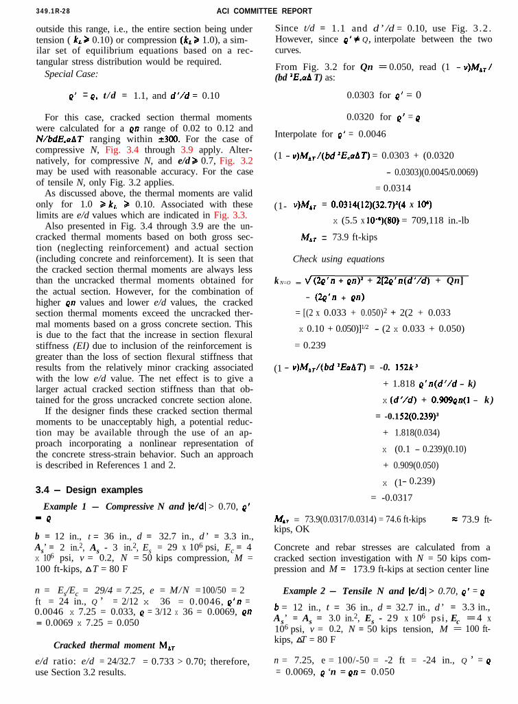
3.4 - Design examples
Example 1 - Compressive=o
b = 12 in., t = 36 in., d =As’ = 2 in.2, As - 3 in.2, Esx 106 psi, v = 0.2, N = 50100 ft-kips, _̂ T = 80 F
N and le/dl > 0.70, Q’
32.7 in., d ’ = 3.3 in.,= 29 x 106 psi, Ec = 4kips compression, M =
n = Es/Ec = 29/4 = 7.25, e = M/N = 100/50 = 2ft = 24 in., Q ’ = 2/12 x 36 = 0.0046, Q’n =0.0046 x 7.25 = 0.033, Q = 3/12 x 36 = 0.0069, Qfl
Since t/d = 1.1 and d ’ /d = 0.10, use Fig. 3 .2 .However, since Q’ f Q, interpolate between the twocurves.
From Fig. 3.2 for Qn = 0.050, read (1 - Y)&/(bd ‘E,aA T) as:
0.0303 for Q’ = 0
0.0320 for Q’ = Q
Interpolate for Q’ = 0.0046
(1 - u)MdT/(bd ‘E,aAT) = 0.0303 + (0.0320
- 0.0303)(0.0045/0.0069)
= 0.0314
(1- v)M*, = 0.0314(12)(32.7)2(4 x 106)
x (5.5 x 10e6)(80) = 709,118 in.-lb
MbT = 73.9 ft-kips
Check using equations
k N=O = f(2Q’fl + Qn)’ + 2[2Q’n(d’/d) + Qn]
- (2Q'n + QIJ)
= [(2 x 0.033 + 0.050)2 + 2(2 + 0.033
x 0.10 + 0.050)]1/2 - (2 x 0.033 + 0.050)
= 0.239
(1 - u)MdT/(bd ‘EaAT) = -0. 152k3
+ 1.818 Q’n(d’/d - k)
x (d’/d) + 0.909Qn(l - k )
= -0.1 52(0.239)3
+ 1.818(0.034)
x (0.1 - 0.239)(0.10)
+ 0.909(0.050)
x (1- 0.239)
= -0.0317
M,, = 73.9(0.0317/0.0314) = 74.6 ft-kipskips, OK
= 73.9 ft-
Concrete and rebar stresses are calculated from acracked section investigation with N = 50 kips com-pression and M = 173.9 ft-kips at section center line
Example 2 - Tensile N and le/dl > 0.70, Q’ = Q6 = 12 in., t = 36 in., d = 32.7 in., d ’ = 3.3 in.,As’ = As = 3.0 in.2, Es - 29 x 106 psi , Ec = 4 x10⁶ psi, v = 0.2, N = 50 kips tension, M = 100 ft-kips, _̂ T = 80 F
n = 7.25, e = 100/-50 = -2 ft = -24 in., Q ’ = Q= 0.0069, Q ‘n = Qn = 0.050
DESIGN FOR THERMAL EFFECTS/NUCLEAR PLANTS 349.1R-29
For en = 0.05, (1 - v)M*J bd *E,aA T= ti(O.035 + 0.046) = 0.0405
J%T = 0.0405(1.25)(12)(32.7)‘(4)(5.5)(80)
= 95.3 ft-kips
Mdf = 95.3 ft-kips
Concrete and rebar stress are calculated from acracked section investigation with N = 100 kipscompression and M = 195.3 ft-kips at section centerline.
Example 4 - Tensile N and /e/d1 < 0.70
Same as Example 3 except N = 60 kips tension
e = 100 ft-kips/(-60 kips) = -1.67 ft = -20 in.,e/d = -20/32.7 = -0.612 or le/dl = 0.612
From Fig. 3.3 for en = 0.05, the lower limit onle/dl is 0.575 for the tensile N case. Since 0.612 >0.575, use Fig. 3.2.
From Fig. 3.2, with Qn = 0.05, read (1 - v)MJ(bd *E,aAT) =
KT ==
MbT =
Concrete and
0.032
0.032(1.25)( 12)(32.7)‘(4)(5.5)(80)
75.3 ft-kips
75.3 ft-kips
rebar stresses are calculated from acracked section investigation with N = 60 kips ten-sion and M = 175.3 ft-kips at section center line.
CHAPTER 4-REFERENCES
4.1-Recommended referencesThe document of the standards-producing organi-
zation referred to in this document is listed belowwith its serial designation.
American Concrete Institute349 Code Requirements for Nuclear Safety Related
Concrete Structures and Commentary
4.2-Cited references1. Gurfinkel, G., "Thermal Effects in Walls of Nuclear
Containments-Elastic and Inelastic Behavior,” Proceed-ings, First International Conference on StructuralMechanics in Reactor Technology (Berlin, 1971), Commis-sion of the European Communities, Brussels, 1972, V. 5-J,pp. 277-297.
2. Kohli, T., and Gurbuz, O., “Optimum Design ofReinforced Concrete for Nuclear Containments, IncludingThermal Effects,” Proceedings, Second ASCE SpecialtyConference on Structural Design of Nuclear Plant Facil-ities (New Orleans, 1975), American Society of Civil En-gineers, New York, 1976, V. 1-B. pp. 1292-1319.
This report was submitted to letter ballot of the committee,which consists of 33 members; ballot results were 28 affirma-tive, 2 negative, and 3 not returned.
Omesh B. AbhatHans AsharTed M. BrownEdwin G. BurdetteOral BuyukozturkR. W. Cannon*King-Yuen ChuJames F. CostelloVijay K. DattaThomas J. Duffy
Consulting Members:M. BenderHarold S. Davis
---*Prime authors of the thermal effects
ACI COMMITTEE 349Concrete Nuclear Structures
Richard S. Orr James R. CraneChairman Secretary
Alan M. EbnerJames F. Fulton*Dwaine A. GodfreyGunnar A. HarsteadRobert P. KennedyJohn C. KingRonald A. LangKenneth Y. LeeRomuald E. LipinskiThou-Han LiuFrederick L. Moreadith
Myle J. Holley, Jr.Morris Schupack
Committee members voting on the 1992 revisions:
John K. McCallChairman
Marvin A. ConesSecretary
Richard J. NetzelDragos A. NutaDuke OakesJulius V. RotzSubir K. SenHemant H. ShahRobert E. ShewmakerEric C. SmithLee SternRichard H. Toland
Chester P. Siess
Omesh B. AbhatHans G. AsharTed M. BrownRobert W. CannonRonald A. CookThomas J. Duffy
W. Bryant FryeDwaine A. GodfreyHerman L. Graves IIIGunnar A. HarsteadCharles J. HookhamRichard E. Klingner
T.H. Liu Robert E. ShewmakerTimothy L. Moore Chen P. TamFrederick L. Moreadith Richard M. TolandDragos A. Nuta Donald T. WardRichard S. Orr Albert Y.C. WongJulius V. Rotz Charles A. Zalesiak