68
Part Number 129777-01 Revision A, January 1996 3500 Monitoring System Rack Configuration and Utilities Guide

Part Number 129777-01Revision A, January 1996
3500 Monitoring SystemRack Configuration and Utilities Guide

Copyright © 1995 Bently Nevada CorporationAll Rights Reserved.
No part of this publication may be reproduced, transmitted, stored in a retrieval system ortranslated into any human or computer language, in any form or by any means, electronic,mechanical, magnetic, optical, chemical, manual, or otherwise, without the prior writtenpermission of the copyright owner,
Bently Nevada CorporationPost Office Box 157
Minden, Nevada 89423
Copyright infringement is a serious matter under the United States of America and foreigncopyright laws.

iii
ContentsIntroduction
Setting Up a New Rack . . . . . . . . . . . . . . . . . . . . . . . . . . . . . . . . . . . . . 1
Installing the SoftwareComputer Requirements . . . . . . . . . . . . . . . . . . . . . . . . . . . . . . . . . . . . . 3Installation Instructions . . . . . . . . . . . . . . . . . . . . . . . . . . . . . . . . . . . . . 3
Running the Configuration SoftwareWays to Use Rack Configuration Software . . . . . . . . . . . . . . . . . . . . . . 6
Configuring a New Rack . . . . . . . . . . . . . . . . . . . . . . . . . . . . . . . . . 6Building a Rack Configuration . . . . . . . . . . . . . . . . . . . . . . . . . . . . 6Modifying a Rack Configuration . . . . . . . . . . . . . . . . . . . . . . . . . . . 7
Using the Main Configuration Screen . . . . . . . . . . . . . . . . . . . . . . . . . . . 8Connecting a Computer to a 3500 Rack . . . . . . . . . . . . . . . . . . . . . . . . 10
Direct Connection S RS232 . . . . . . . . . . . . . . . . . . . . . . . . . . . . . . 11Direct Connection S RS422 . . . . . . . . . . . . . . . . . . . . . . . . . . . . . . 12Remote Communication . . . . . . . . . . . . . . . . . . . . . . . . . . . . . . . . . 13Network Connection . . . . . . . . . . . . . . . . . . . . . . . . . . . . . . . . . . . 15
Initiating Communication with a 3500 Rack . . . . . . . . . . . . . . . . . . . . . 15Discontinuing Communication with a 3500 Rack . . . . . . . . . . . . . . . . . 16Uploading and Downloading Configurations . . . . . . . . . . . . . . . . . . . . 17Opening and Saving Configuration Files . . . . . . . . . . . . . . . . . . . . . . . 19Printing Catalog Numbers . . . . . . . . . . . . . . . . . . . . . . . . . . . . . . . . . . 19Copying Configuration Information . . . . . . . . . . . . . . . . . . . . . . . . . . . 20
Copying Monitor Channel Configurations . . . . . . . . . . . . . . . . . . . 20Copying Channel Setpoints . . . . . . . . . . . . . . . . . . . . . . . . . . . . . . 21Copying Module Configurations . . . . . . . . . . . . . . . . . . . . . . . . . . 21
Configuring the Modules in a RackConfiguring the Rack Interface Module . . . . . . . . . . . . . . . . . . . . . . . . 24Configuring Keyphasor Modules . . . . . . . . . . . . . . . . . . . . . . . . . . . . . 26Configuring Monitors . . . . . . . . . . . . . . . . . . . . . . . . . . . . . . . . . . . . . 27
Setting Monitor and Channel Options . . . . . . . . . . . . . . . . . . . . . . 27Setting Alarm Setpoints . . . . . . . . . . . . . . . . . . . . . . . . . . . . . . . . . 29
Configuring Relay Modules . . . . . . . . . . . . . . . . . . . . . . . . . . . . . . . . . 31Configuring Communication Gateway Modules . . . . . . . . . . . . . . . . . . 33
iv
Defining the Contents of Registers . . . . . . . . . . . . . . . . . . . . . . . . . 33Setting Communication Gateway Communication Parameters . . . . . 35
Configuring a Triple Modular Redundant Rack . . . . . . . . . . . . . . . . . . . 37Software Operation for TMR Systems . . . . . . . . . . . . . . . . . . . . . . 37Configuring TMR Functions . . . . . . . . . . . . . . . . . . . . . . . . . . . . . . 38
Using the Rack Configuration UtilitiesSetting Module and Channel Switches . . . . . . . . . . . . . . . . . . . . . . . . . . 40Setting the 3500 Rack Date and Time . . . . . . . . . . . . . . . . . . . . . . . . . . 41Disabling Alarms . . . . . . . . . . . . . . . . . . . . . . . . . . . . . . . . . . . . . . . . . 41Enabling Trip Multiply . . . . . . . . . . . . . . . . . . . . . . . . . . . . . . . . . . . . . 42Rack Reset . . . . . . . . . . . . . . . . . . . . . . . . . . . . . . . . . . . . . . . . . . . . . . 42Viewing the System Event List . . . . . . . . . . . . . . . . . . . . . . . . . . . . . . . 42Viewing the Alarm List . . . . . . . . . . . . . . . . . . . . . . . . . . . . . . . . . . . . . 43Verifying the Operation of a 3500 Rack . . . . . . . . . . . . . . . . . . . . . . . . 44
Running the Test UtilitiesStarting the Utilities . . . . . . . . . . . . . . . . . . . . . . . . . . . . . . . . . . . . . . . 46RIM Host Port Test Utility . . . . . . . . . . . . . . . . . . . . . . . . . . . . . . . . . . 47
Setting Up Communications . . . . . . . . . . . . . . . . . . . . . . . . . . . . . . 48Displaying Test Data . . . . . . . . . . . . . . . . . . . . . . . . . . . . . . . . . . . 48
Communication Gateway Port Test . . . . . . . . . . . . . . . . . . . . . . . . . . . . 50Setting up Communications . . . . . . . . . . . . . . . . . . . . . . . . . . . . . . 51Displaying Test Results . . . . . . . . . . . . . . . . . . . . . . . . . . . . . . . . . 51
Files Used by Configuration SoftwareDescription by File Extension . . . . . . . . . . . . . . . . . . . . . . . . . . . . . . . . 54List of Files . . . . . . . . . . . . . . . . . . . . . . . . . . . . . . . . . . . . . . . . . . . . . 55
Cable Part Numbers and DiagramsCable Part Numbers . . . . . . . . . . . . . . . . . . . . . . . . . . . . . . . . . . . . . . . 57Cable Pin Out Diagrams . . . . . . . . . . . . . . . . . . . . . . . . . . . . . . . . . . . . 57
Modem File Programming Information

v

Introduction
1
IntroductionThis manual shows how to use the following software that comes with the 3500Monitoring system.
Software Name Function
Rack Configuration Set operating parameters so that all themodules in a 3500 monitoring rack worktogether.
RIM Host Port Test Test the output of the CONFIGURATIONPORT on the Rack Interface Module (frontof the rack) and the Host Connector on theRack Interface I/O Module (rear of the rack).
Comm Gateway Port Test Test the HOST and RACK ports on theComm Gateway I/O module.
Setting Up a New RackUse the following procedure to set up, configure, and verify a new rack. If yourrack has a custom configuration from the factory, skip step 5.
1. Set the hardware switches and jumpers on the Rack Interface Module(RIM), the backplane, the 3500/42 Monitors, and the relay modules. The3500 Monitoring System Rack and Installation Manual shows how to setthe jumper on the backplane. The other jumper settings are described in theoperation and maintenance manuals for the RIM, the 3500/42 Monitor, andthe relay modules.
2. Connect the field wiring to the rack as described in the operation andmaintenance manuals for all the modules installed in the rack and in the3500 Field Wiring Diagram Package (part number 130432-01).

Rack Configuration and Utilities Guide
2
3. Test all of the communication ports on the rack by using the test utilitieslisted in the following table:
Port to be Location of Utility to use... Refer to page...tested... port...
CONFIGUR- Rack Interface RIM Host Port 47ATION PORT Module Test Utility
HOST Rack Interface RIM Host Port 47I/O Module Test Utility
HOST and Comm Gateway Comm Gateway 50RACK I/O Module Port Test Utility
4. Configure the rack using the 3500 Rack Configuration Software.
5. Adjust the zero position voltage and scale factor for all monitors in the rackby using the Adjust Button on the channel options screens.
6. Use the verification procedures in the operation and maintenance manualsfor the modules in the rack and the Verify option in the Rack ConfigurationSoftware to verify that the rack is configured and operating correctly.
Installing the Software
3
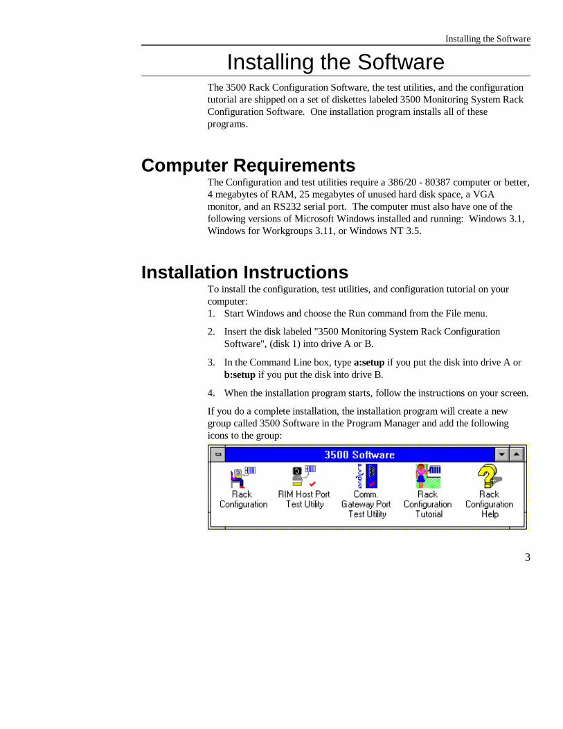
Installing the SoftwareThe 3500 Rack Configuration Software, the test utilities, and the configurationtutorial are shipped on a set of diskettes labeled 3500 Monitoring System RackConfiguration Software. One installation program installs all of theseprograms.
Computer RequirementsThe Configuration and test utilities require a 386/20 - 80387 computer or better,4 megabytes of RAM, 25 megabytes of unused hard disk space, a VGAmonitor, and an RS232 serial port. The computer must also have one of thefollowing versions of Microsoft Windows installed and running: Windows 3.1,Windows for Workgroups 3.11, or Windows NT 3.5.
Installation InstructionsTo install the configuration, test utilities, and configuration tutorial on yourcomputer:1. Start Windows and choose the Run command from the File menu.
2. Insert the disk labeled "3500 Monitoring System Rack ConfigurationSoftware", (disk 1) into drive A or B.
3. In the Command Line box, type a:setup if you put the disk into drive A orb:setup if you put the disk into drive B.
4. When the installation program starts, follow the instructions on your screen.
If you do a complete installation, the installation program will create a newgroup called 3500 Software in the Program Manager and add the followingicons to the group:

Rack Configuration and Utilities Guide
4
Running the Configuration SoftwareA 3500 rack can contain a variety of modules that can be set up to operatedifferent ways. The process of setting system, module, and channel options sothat all the modules in a 3500 rack work together is called configuration.
Configuring a 3500 rack consists of using the Rack Configuration Software toset options and then downloading the settings to the rack. You can use theprogram two ways: You can run the program at any convenient place, save thesettings in configuration files, and then later download the configuration to therack. Or you can connect the computer to the rack first and then upload anddownload the configuration as required.
In this Section...
topic page topic page
Ways to Use Rack Configuration Uploading and DownloadingSoftware 6 Configurations 17
Using the Main Configuration Opening and Saving ConfigurationDisplay 8 Files 19
Connecting a Computer to a 3500 Copying ConfigurationRack 10 Information 20
Initiating Communication with a3500 Rack 15

Running the Configuration Program
5
Ways to Use Rack Configuration SoftwareThe following lists illustrate the typical uses of the Rack ConfigurationSoftware.
Configuring a New RackA 3500 Monitoring Rack cannot operate without a valid configuration. Use thisprocess after you have installed the rack, set all switches and jumpers, andconnected transducers. If your rack came with a custom configuration from thefactory, you can skip this procedure.
Process step... Refer to page...
Connect the computer to the rack 10Initiate communication 15Upload the default configuration from the rack 17Modify the default ConfigurationDownload the configuration to the rack 17Discontinue communication 17Disconnect the computer from the rack
Building a Rack ConfigurationUse this process if you choose to prepare a series of configuration files at yourdesk and then download the files to the racks at a later time.
Process step... Refer to page...
Identify the modules in slots 1 through 15 8Set Rack Interface Module options 24Set Keyphasor options 26Set Monitor options 27Set channel options for monitor modules 27Set Comm Gateway options 33Set alarm setpoints for monitor modules 29Set alarm drive logic for relay channels 31Save the configuration file 19
Rack Configuration and Utilities Guide
6
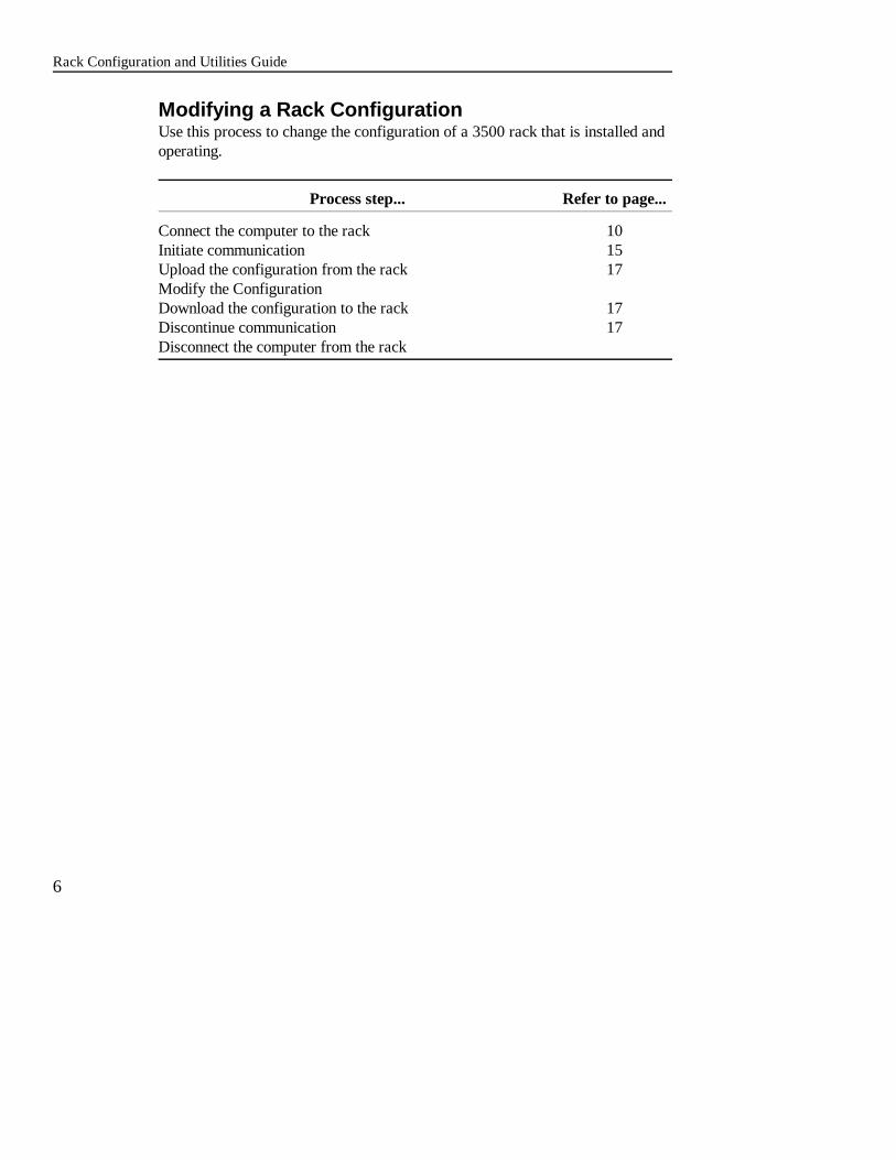
Modifying a Rack ConfigurationUse this process to change the configuration of a 3500 rack that is installed andoperating.
Process step... Refer to page...
Connect the computer to the rack 10Initiate communication 15Upload the configuration from the rack 17Modify the ConfigurationDownload the configuration to the rack 17Discontinue communication 17Disconnect the computer from the rack

Running the Configuration Software
7
Reference InformationS helps you keep trackof which rack and rackfile you are configuring.
Mode Buttons and Indicator S control how the RackConfiguration Software operates.
Menu Bar S access commands to connect to a rack, manipulate configuration files, copyconfiguration settings from one module to another, and control the operation of the rack.
Rack Diagram S showsthe modules that areinstalled in the rack. Use this diagram andthe Options andSetpoints mode buttonsto move to configuration screens.
Using the Main Configuration ScreenThe following figure lists the parts of the Main Configuration Screen andsummarizes how to use them.

Rack Configuration and Utilities Guide
8
Set module and channel options.Enter the Module Option screen by clicking the Optionsbutton and then clicking on the module to be configured.
Set alarm setpoints for channels in monitor modulesEnter the Alarm Setpoint screen by clicking on theSetpoints push button and then clicking on the monitormodule to be configured.
Build a rack.Place modules in slots 1 through 15 by clicking on a slotand then selecting a module from the drop down list.
Although you can enter most configuration settings in any order you choose, werecommend that you create a rack configuration by using the mode buttons onthe Main Configuration display from top to bottom as suggested in thefollowing figure. Because these buttons control how the Configuration Softwareoperates, be sure that the correct button is depressed before you proceed with anoperation.

Running the Configuration Software
9
Connecting a Computer to a 3500 RackYou can connect a computer to a 3500 Monitoring rack the following threeways:
Method for Use this method...Connecting
Direct to temporarily connect your computer when the computer isnear the 3500 rack. Direct connection can use RS232 orRS422 protocol.
Remote to connect a 3500 rack to a computer that is located off site. The computer must have a modem and the 3500 rack musthave access to a dedicated phone line.
Network if your computer is connected to a network that has a stationthat is connected to the HOST connector on the RackInterface I/O module of a 3500 rack and is running the DataAcquisition DDE Server Software.

Rack Configuration and Utilities Guide
10
Direct Connection to the Rack Interface Module
Direct Connection S RS232Connect the computer directly to the rack by using an RS232 cable (BentlyNevada part number 130118-XXXX-XX) as shown in the following figure. Ifthe Rack Interface I/O Module does not have an internal modem, you can alsoconnect the RS232 cable to the Rack Interface I/O Module by using the portlabeled HOST. Set the switch below the port to the RS232 position.
Using the CONFIGURATION PORT lets you configure only the rack that yourcomputer is connected to. Using the HOST port on the Rack Interface I/OModule lets you use the rack address to configure all of the racks connected inthe daisy chain.

Running the Configuration Software
11
Direct Connection Using RS422 Protocol
Direct Connection S RS422If the Rack Interface I/O Module does not have an internal modem, you canconnect the computer directly to the rack using RS422 communication. Installan RS232-to-RS422 converter between the computer and the rack. The cablefrom the converter should be connected to the port on the rear of the RackInterface I/O Module labeled HOST. Set the switch below the port to theRS422 position.
An alternate method of direct connection to RS422 is to install an RS422/485Data Aquisition Card (Bently Nevada part number 02230415) in your PC, andusing the Host to 3500 Rack RS422 Interface Cable (Bently Nevada partnumber 132632-XXXX-XX for PVC insulation or 132633-XXXX-XX forTeflon insulation). Connect the cable from the RS422 Card to the port on therear of the Rack Interface I/O Module labeled HOST. Set the switch below theport to the RS422 position.

Rack Configuration and Utilities Guide
12
With InternalModem
With RS232/422connector.
Connecting the Computer to a Rack using a Modem
Remote CommunicationThe 3500 Monitoring Rack has two versions of the Rack Interface I/O Module: one with a RS232/422 terminal and one with an internal modem. The internalmodem will operate at speeds up to 14.4 kbaud.
Many laptop computers and some desktop models also contain internal modems. Baud rates on these modems can vary from 4800 to 28.8 kbaud. The modem-to-modem communication speed is determined by the quality of the phoneconnection and the protocol of the information being transmitted. The speed atwhich the computer communicates with the modem does not have to be identicalto the modem-to-modem communication rate.
To use modems to connect the computer and the rack:1. Verify that you have dedicated telephone communications available at the
computer and rack locations.

Running the Configuration Program
13
3500 Rack with Internal Modem
Standard modem cable
3500 Rack with External Modem
Standardmodem cable
2. At the computer: Connect the phone line to the internal or external modemphone port. If you use an external modem, connect a standard modem cablebetween the computer serial COM port and the modem.
3. At the rack: Connect the phone line to the internal modem on the RackInterface I/O Module. If you use an external modem, connect the standardmodem cable to the port labeled CONFIGURATION PORT on the front ofthe RIM or to the port labeled HOST on the Rack Interface I/O Module. Verify that the RS232/RS422 switch on the I/O module is set to the RS232position.
The following figures show some of the ways for using modems to connect thecomputer to the rack.
Note: The Rack Interface Module (RIM) configuration must be set to indicatea modem is present on the front or rear 3500 RIM port.

ConfiguringComputer
Data AcquisitionDDE server
Ethernet cable
Daisy-chained3500 racks
Rack Configuration and Utilities Guide
14
Network ConnectionIf the configuring computer has network access to a Data Acquisition DDEServer as shown in the following figure, you can configure all racks that aredaisy chained to the server by using the Network connection.
Dynamic Data Exchange (DDE) is a method of exchanging or providing data toand from Windows applications. This method lets multiple devices access thedata simultaneously.
Initiating Communication with a3500 RackAfter you have connected the computer to the rack and started the RackConfiguration Software, use the following procedure to initiate communicationbetween the rack and the computer:1. Select the Connect option in the File menu. A list of connection methods
will appear (Direct, Remote, and Network).
2. Select the connection method that corresponds to how your computer isconnected to the rack(s) that you will configure. Refer to the previoussection for information about these methods.
3. Enter the appropriate communication parameters into the connect dialog boxusing the following table for reference:

Running the Configuration Software
15
Communication DescriptionParameter
Connect Password The password on the 3500 rack to be configured. This password is set when the RIM options areconfigured.
Rack Address The setting on the RACK ADDRESS switch on theRack Interface Module in the 3500 rack to beconfigured.
Com Port The connector on the configuring computer used tocommunicate with the 3500 rack.
Baud The rate of the computer-to-modem or Computer-to-rack communication.
Phone Number The phone number of the modem for the 3500 rack tobe configured
Data Acquisition (DDE) The network name of the computer that is runningServer Computer Name 3500 Data Acquisition software and that is connected
to the daisy-chained 3500 racks to be configured.4. Initiate communication by clicking on Connect. A successful connect to the
rack is indicated by the message "Connection established".
Discontinuing Communication with a 3500Rack
Before you disconnect the cable between the configuring computer and the rack,discontinue communication by clicking on the Disconnect command in the Filemenu. This command initiates the following actions:C return any module that is still in configuration mode to run mode (under
user control)
C release the configuration token if the configuring computer has the token
C hang up the modem if the computer was using remote communication

Rack Configuration and Utilities Guide
16
Although disconnecting the cables without invoking the Disconnect commandcauses no harm, we recommend using the command when you're finishedcommunicating with a rack.
Uploading and Downloading ConfigurationsYou transfer configuration settings between the configuring computer and therack to be configured by using a process called uploading (rack to computer) ordownloading (computer to rack). The Upload and Download commands are inthe File menu.
To upload a configuration:1. Connect the configuring computer to the rack to be configured. (Refer to
page 10 of this manual.)
2. Establish communication with the rack by using the procedure in the"Initiating Communication with a 3500 Rack" section.
3. Click on the Upload command in the File menu. A prompt will appear thatindicates the progress of the upload and indicates if the upload wassuccessful.
4. Terminate communication with the rack by clicking on the Disconnectcommand in the File menu.
5. Disconnect the configuring computer from the rack.
If an error occurs while uploading a configuration from the rack, the upload willcontinue and the default configuration will be loaded for the module where theerror occurred.
To download a configuration:1. Connect the configuring computer to the rack to be configured. (Refer to
page 10 of this manual.)
2. Establish communication with the rack by using the procedure in the"Initiating Communication with a 3500 Rack" section.
3. Move the configuration keylock on the front panel of the Rack InterfaceModule from Run to Program. (All functions of the rack will continueoperating with the keylock set to Program.)
Running the Configuration Software
17
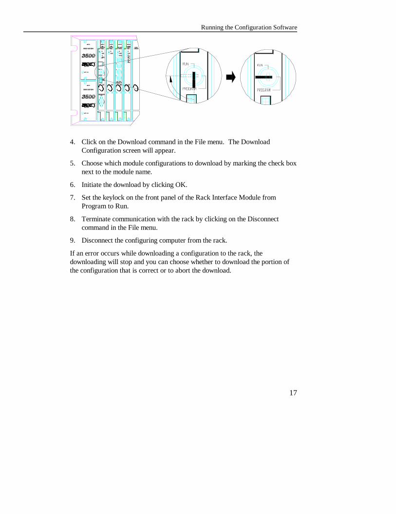
4. Click on the Download command in the File menu. The DownloadConfiguration screen will appear.
5. Choose which module configurations to download by marking the check boxnext to the module name.
6. Initiate the download by clicking OK.
7. Set the keylock on the front panel of the Rack Interface Module fromProgram to Run.
8. Terminate communication with the rack by clicking on the Disconnectcommand in the File menu.
9. Disconnect the configuring computer from the rack.
If an error occurs while downloading a configuration to the rack, thedownloading will stop and you can choose whether to download the portion ofthe configuration that is correct or to abort the download.

Rack Configuration and Utilities Guide
18
Opening and Saving Configuration FilesUse the Open command in the File menu to load a configuration file that hasbeen stored on disk into the Rack Configuration Software.
Use the Save command to store the current configuration in the RackConfiguration Software to a file on disk. We recommend that you save theconfiguration of all 3500 Monitoring Racks to files on disk.
All rack configuration files contain a maximum of 8 characters and end with afile name extension of .RAK. The default directory for configuration files is\3500\trains\primcfg. Although you can place the files in any directory, keep thefollowing special considerations in mind:C If multiple 3500 racks are daisy chained together, place the rack
configuration files for these racks in the same directory.
C If the 3500 Data Acquisition Software is to provide historical trend data,place all rack configuration files for the racks daisy chained to the DataAcquisition computer in the \3500\trains\primcfg directory.
Printing Catalog NumbersThe Print menu lets you print a list of the catalog numbers of all the modulesthat are displayed on the Main Configuration screen. This option makes it easyto order a new 3500 rack or to order replacement modules for an existing rack.

Running the Configuration Software
19
The arrow buttons let youcopy channel settingsbetween channels in achannel pair...
... or from one channel pairto another.
Copying Configuration InformationThe 3500 Rack Configuration Software makes it easy to copy the configurationsettings of channels and modules.
Copying Monitor Channel Configurations
An equal sign between the arrow buttons indicates that the configuration of thechannels or channel pairs are the same. "Copy" indicates that the configurationof the channels or channel pairs are not the same. The arrow buttons copy themonitor options but not the alarm setpoints.
Rack Configuration and Utilities Guide
20
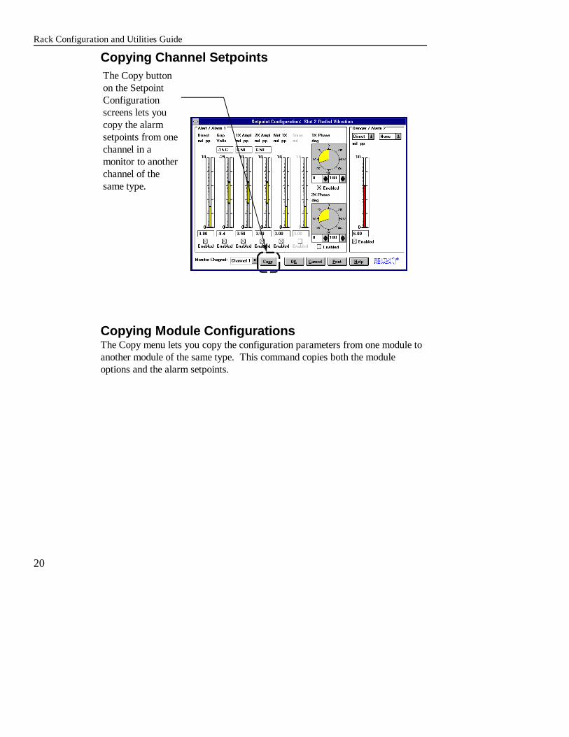
The Copy buttonon the SetpointConfigurationscreens lets youcopy the alarmsetpoints from onechannel in amonitor to anotherchannel of thesame type.
Copying Channel Setpoints
Copying Module ConfigurationsThe Copy menu lets you copy the configuration parameters from one module toanother module of the same type. This command copies both the moduleoptions and the alarm setpoints.

Running the Configuration Software
21
Use the upper row ofbuttons to choose theslot of the module withthe configuration thatyou want to copy.
Use the lower row ofbuttons to choose the slotor slots that you willcopy the configurationto.
If the slot or slots chosen in the lower row of buttons do not contain the sametype of module as in the slot chosen in the upper row, the program will replacethe module before it copies the configuration parameters.
Rack Configuration and Utilities Guide
22
Configuring the Modules in a RackConfigure a 3500 rack by setting the operating parameters for all modules in therack and for all channels in each module. You set these parameters by usingdialog boxes that appear when you click on the Options button and then on amodule. The dialog boxes use conventional Windows selection tools like checkboxes, radial buttons, and drop down lists. If you are not familiar with thesetools, refer to your Windows documentation. The online help system for theRack Configuration Software contains definitions of all the configurationoptions.
In this section...
topic page topic page
Configuring the Rack Interface Configuring Relay Modules 31Module 24
Configuring Keyphasor Modules 33Modules 26
Configuring Monitors 27 Redundant Rack 37
Configuring Comm Gateway
Configuring a Triple Modular
Configuring the Modules in a Rack
23
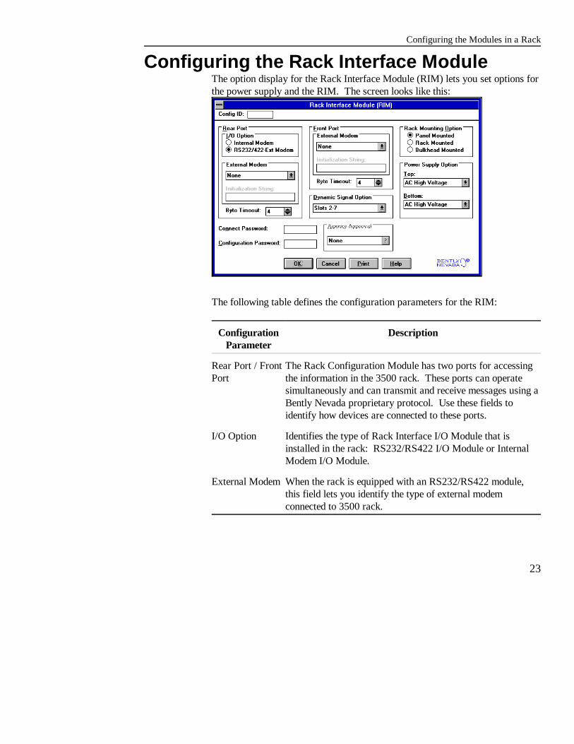
Configuring the Rack Interface ModuleThe option display for the Rack Interface Module (RIM) lets you set options forthe power supply and the RIM. The screen looks like this:
The following table defines the configuration parameters for the RIM:
Configuration DescriptionParameter
Rear Port / Front The Rack Configuration Module has two ports for accessingPort the information in the 3500 rack. These ports can operate
simultaneously and can transmit and receive messages using aBently Nevada proprietary protocol. Use these fields toidentify how devices are connected to these ports.
I/O Option Identifies the type of Rack Interface I/O Module that isinstalled in the rack: RS232/RS422 I/O Module or InternalModem I/O Module.
External Modem When the rack is equipped with an RS232/RS422 module,this field lets you identify the type of external modemconnected to 3500 rack.

Rack Configuration and Utilities Guide
Configuration DescriptionParameter
24
Byte Timeout The number of bytes of communication line "dead time"needed to signal an end of message. Each port on the RackInterface Module may have a different Byte Timeout setting.
Connect A password that "gates" all access to the 3500 rack. WithoutPassword this password, the Rack Interface Module will not accept
commands or requests from an external personal computer.
Configuration A password that "gates" configuration information to bePassword downloaded to a 3500 rack. Without this password, the Rack
Interface Module will not accept any configuration commandsfrom an external personal computer.
Dynamic Signal The monitors that will provide data to the External DynamicOption Data Interface (DDIX) or the External Transient Data
Interface (TDIX). The DDIX and TDIX are Bently Nevadacommunication processors.
Agency Approval The agency approval for the 3500 rack. The option selectedin this field must match the approval rating of the rack.
Mounting Option The mounting configuration of the rack being configured. Theoption selected in this field must match the mounting option ofthe rack.
Power Supply The power supplies that are installed in the rack.Top / Bottom

Configuring the Modules in a Rack
25
Configuring Keyphasor ModulesConfigure Keyphasor modules by completing the configuration parameters onthe Keyphasor screen.
The following table defines the configuration parameters for the KeyphasorModule:
Configuration DescriptionParameter
Signal Polarity The type of mark observed by the Keyphasor transducer Snotch or projection.
Type The type of Keyphasor transducer connected to the KeyphasorI/O Module
Hysteresis The voltage level above and below the threshold value whichis required to trigger the conditioned Keyphasor signal.
Threshold The voltage level of the input signal from the Keyphasortransducer where the conditioned Keyphasor signal istriggered.
Rack Configuration and Utilities Guide
Configuration DescriptionParameter
26
Events Per The number of pulses in a Keyphasor signal for each shaftRevolution rotation.
Orientation The location of the Keyphasor transducer on the machine.
Upper RPM The upper limit of the full scale range for the Keyphasor rpm. Limit The Keyphasor Module will scale the rpm value between 0
and this value.
RPM Clamp The value that the data provided through the CommunicationValue Gateway will be clamped to when a Keyphasor transducer
goes invalid.
I/O Module The type of I/O module connected to the Keyphasor Module.
Configuring MonitorsThe two steps for configuring monitors are setting monitor and channel optionsand setting alarm setpoints.
Setting Monitor and Channel OptionsMonitors have two dialog boxes for setting options. The first box is for settingmonitor options and looks similar to the following screen.

Configuring the Modules in a Rack
27
The second box is for setting options for each channel in the monitor moduleand looks like this:

Rack Configuration and Utilities Guide
28
...or by entering thesetpoint value in thenumber boxes. Thealarm will occur ifthe value movesoutside of thecolored area in thebar graph.
Adjust all alarmsetpoints exceptphase by eitherclicking anddragging thebargraph...
Choose up to twoproportional valuesthat will havesetpoints for dangeralarms.
Setting Alarm SetpointsAn alarm setpoint is the level of the proportional value at which an alarm willoccur if the value moves above or below the level. To set alarm setpoints, usethe monitor option displays to enable alarms and use this approach:

Configuring the Modules in a Rack
29
If the red or yellow area is outside of theintended acceptance region, reverse theangle values in the number boxes.
Adjust the phase angle for 1X or 2Xacceptance regions by entering the anglesinto the number boxes above or below theangle diagrams. The acceptance region isindicated by the yellow or red area in thecircle.

S02C03A2Alarm level (2) / DangerChannel number (3)Slot number (2)
S02C##A2Code applies toall channels inin the monitor slot
Rack Configuration and Utilities Guide
30
Click on a module...
Choose the relaychannel to configure inthis group box.
...the list of alarms for themodule will be displayedhere. The number ofalarms depends on whatchannels are active andwhich alarms areconfigured.
Configuring Relay ModulesUse the Relay Association screen to enter the alarm logic that controls whatalarms cause the relays to activate. Enter the Relay Association screen byclicking on the Options pushbutton and then clicking on the relay module to beconfigured. To enter the alarm logic:
The alarm logic in the Relay Association window contains the logic that controlswhen a relay channel is activated. The logic consists of alarm codes, AND (*)and OR (+) symbols, and parentheses. The AND operator has precedence overthe OR operator and parentheses are used to control the order of the operatorsfor complex logic. When the logic is true, the relay for that channel willactivate.
This figure showsthe meaning of thedigits in alarmcodes:

Configuring the Modules in a Rack
31
Add an alarm code byclicking on the code and thenclicking Enter or by doubleclicking on the code. Thealarm code will appear inthe Alarm Drive Logic box.
Add AND, OR, andparentheses to the alarmlogic by clicking on thesebuttons.
Use the left arrow button tobackspace one character inthe string. Use the CLRbutton to clear the alarmlogic box and start over.
To enter alarm logic for the channel:

Rack Configuration and Utilities Guide
32
Enter the number of channels whoseprimary values will be included inthe message
The number in parenthesis indicatesnumber of channels in the modulethat have proportional values.
Configuring Communication GatewayModules
The Communication Gateway screen lets you enable a Distributed ControlSystem (DCS) computer to scan 3500 racks more efficiently and set thecommunication parameters of the HOST and RACK ports on the CommGateway I/O Module.
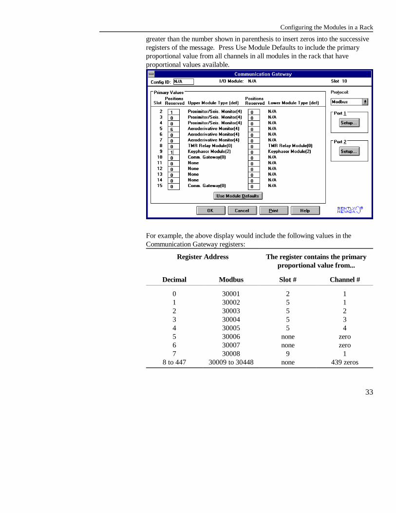
Defining the Contents of RegistersRegisters 30001 to 30448 Modbus (0 to 447 decimal) in the CommunicationGateway Module are reserved for the primary proportional values frommonitors and Keyphasor Modules. The Communication Gateway screen letsyou place these primary proportional values into contiguous registers so that aDCS can scan 3500 racks efficiently. You can reduce the scan time byincluding only those values required by the DCS and excluding the contents ofunnecessary or empty registers.
All the other data that is available from the monitors and Keyphasor Modules isstored in fixed registers on the Communication Gateway Module. All fixed andprogrammable registers of the Communication Gateway Modules are describedin the Communication Gateway Operation and Maintenance Manual (partnumber 129769-01).
To define the contents of the reserved registers, enter integers from 0 to 32 intothe number boxes in the columns labeled "Positions Reserved". The integerindicates the number of channels in the modules whose primary proportionalvalue will be included in the message.
Enter 0 to include no values from the module. Enter 4 to include the primaryproportional value from all 4 channels in a module. Enter a number that is
Configuring the Modules in a Rack
33
greater than the number shown in parenthesis to insert zeros into the successiveregisters of the message. Press Use Module Defaults to include the primaryproportional value from all channels in all modules in the rack that haveproportional values available.
For example, the above display would include the following values in theCommunication Gateway registers:
Register Address The register contains the primaryproportional value from...
Decimal Modbus Slot # Channel #
0 30001 2 11 30002 5 12 30003 5 23 30004 5 34 30005 5 45 30006 none zero6 30007 none zero7 30008 9 1
8 to 447 30009 to 30448 none 439 zeros

Rack Configuration and Utilities Guide
34
To determine which values are the primary proportional value for each module,refer to the operation and maintenance manual for that module.
Setting Communication Gateway CommunicationParametersThe Port 1 and Port 2 buttons on the Communications Gateway screen let youset communication parameters for the HOST and RACK connectors on theCommunication Gateway I/O Module. When you click on Port 1 or Port 2, thefollowing window will appear.
The following table describes the fields in this window:
Communication DescriptionParameter
Active Turn a port on (: ) or off (9 ). When a port is turned off, nomachinery data is available.
Address The address of the modbus port on the CommunicationGateway I/O Module.
Connection The type of connection between the 3500 rack and theDistributed Control System (DCS) computer.

Configuring the Modules in a Rack
Communication DescriptionParameter
35
Config Allowed Specify if the 3500 rack can be configured from the DCScomputer. Check (:)the box for yes; clear (9) the box forno. Refer to the Communication Gateway Operation andMaintenance Manual for a list of items which can beconfigured through the Communication Gateway ports.
Parity The type of communication verification contained in eachmessage byte. The parity setting in a CommunicationGateway Module must agree with the setting at the externaldevice connected to the module. Each CommunicationGateway port may be set up with a different parity setting.
Stop Bits The number of bits which will be added to each 3500Communication Gateway message. Each byte within amessage will contain 1 start bit, 8 data bits, and either 1 or 2stop bits. The Stop Bits setting in the CommunicationGateway Module must agree with the setting at the externaldevice connected to the module. Each CommunicationGateway port can have a different Stop Bits setting.
Baud Rate The rate at which messages are transmitted and received fromthe 3500 Communication Gateway. Specifically, it representsthe number of bits which can be transmitted and received fromthe Communication Gateway in 1 second. The Baud Ratesetting in the Communication Gateway Module must agreewith the setting at the external device connected to the module. Each Communication Gateway port can have a different BaudRate setting.
Byte Timeout The amount of time that the Communication Gateway modulewill wait to determine that a command has been received onthe DCS link. This value is expressed as the time required tosend x bytes at the current baud rate.
Full Scale Data The value used to scale the proportional data.Range

Rack Configuration and Utilities Guide
Communication DescriptionParameter
36
Numeric Format The number system that the communication protocol uses tosend and receive data. For the Modbus protocol, the system isHex.
Configuring the Modules in a Rack
37
Configuring a Triple Modular RedundantRack
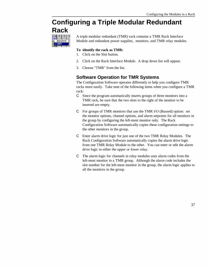
A triple modular redundant (TMR) rack contains a TMR Rack InterfaceModule and redundant power supplies, monitors, and TMR relay modules.
To identify the rack as TMR: 1. Click on the Slot button.
2. Click on the Rack Interface Module. A drop down list will appear.
3. Choose "TMR" from the list.
Software Operation for TMR Systems The Configuration Software operates differently to help you configure TMRracks more easily. Take note of the following items when you configure a TMRrack:C Since the program automatically inserts groups of three monitors into a
TMR rack, be sure that the two slots to the right of the monitor to beinserted are empty.
C For groups of TMR monitors that use the TMR I/O (Bussed) option: setthe monitor options, channel options, and alarm setpoints for all monitors inthe group by configuring the left-most monitor only. The RackConfiguration Software automatically copies these configuration settings tothe other monitors in the group.
C Enter alarm drive logic for just one of the two TMR Relay Modules. TheRack Configuration Software automatically copies the alarm drive logicfrom one TMR Relay Module to the other. You can enter or edit the alarmdrive logic in either the upper or lower relay.
C The alarm logic for channels in relay modules uses alarm codes from theleft-most monitor in a TMR group. Although the alarm code includes theslot number for the left-most monitor in the group, the alarm logic applies toall the monitors in the group.

Rack Configuration and Utilities Guide
38
TMR I/O: Discrete TMR I/O: Bussed
Configuring TMR FunctionsTMR racks have the following additional functions that must be configured: I/O module and Voting.
TMR I/O OptionsMonitors in a TMR group can have input from redundant transducers (TMRI/O: Discrete) or from a single transducer (TMR I/O: Bussed). The followingfigures show the channel 1 input for the TMR I/O options: Discrete and Bussed.
Voting OptionsThe TMR Rack Interface Module continuously checks the output of monitors ina rack by using 2 out of 3 voting. The configuration settings used to control thisvoting are Comparison and % Comparison.
Comparison: The enabled proportional value used in the 2 out of 3 voting.

Configuring the Modules in a Rack
39
% Comparison: The highest allowed percent difference between the middlevalue of the three monitors in a TMR group and the individual values of eachmonitor.
Rack Configuration and Utilities Guide
40
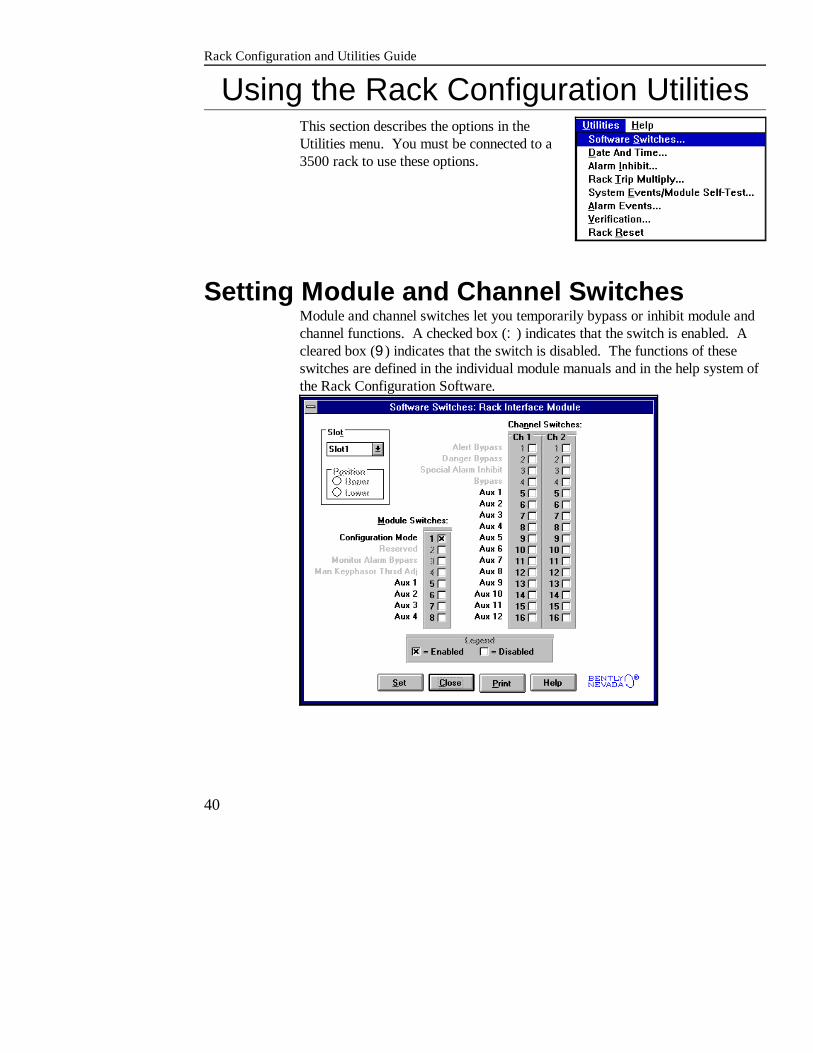
Using the Rack Configuration UtilitiesThis section describes the options in theUtilities menu. You must be connected to a3500 rack to use these options.
Setting Module and Channel SwitchesModule and channel switches let you temporarily bypass or inhibit module andchannel functions. A checked box (:) indicates that the switch is enabled. Acleared box (9) indicates that the switch is disabled. The functions of theseswitches are defined in the individual module manuals and in the help system ofthe Rack Configuration Software.

Using the Rack Configuration Utilities
41
Setting the 3500 Rack Date and TimeUse this dialog box to read or reset the date and time on the clock in a 3500Monitoring rack. The date and time are used to time stamp data collected frommonitor channels and items entered into the Alarm and System Event lists.
Clicking on the Send button will set the rack date and time as follows:
If the Send Host Data and ...the Send Time command will ..Time to Rack box is...
selected send the current data and time of the computerto the rack
not selected send the date and time that is shown in the Dateand Time box to the rack
Clicking on the Read button will cause the configuration software to read anddisplay the date and time from the 3500 rack.
When this dialog box is initially displayed, it will contain the computer's dateand time.
Disabling AlarmsAlarm Inhibit lets you disable alarms (bothalert and danger) and relay activation in therack. This feature is useful when youservice and verify your 3500 rack. Thecurrent status of Rack Alarm Inhibit

Rack Configuration and Utilities Guide
42
(hardware contact and software) are displayed at the top of this screen.
Enabling Trip MultiplyTrip Multiply lets you extend monitor alarmsetpoints by the trip multiply value specifiedin the monitor option. This feature is usefulduring machine ramp-up or ramp-down. The current status of Trip Multiply(hardware contact and software) aredisplayed at the top of this screen.
Rack ResetRack Reset lets you reset latched alarms, latched not OK's and timed OK defeat. This feature is useful when you service and verify your 3500 rack.
Viewing the System Event ListSystem events are actions or occurrences such as configuration changes, moduleerrors, and status messages. The System Event List is filled in a round robinfashion and may contain up to 500 entries. The help system in the RackConfiguration Software defines all the system events.

Using the Rack Configuration Utilities
43
You can run a self-test on any module in a 3500 rack by using the Module Self-test button on the System Events screen. The results of the self-test are postedin the list. The help system in the Rack Configuration Software explains how torun a self-test.
The configuration software uploads 20 events at a time from the 3500 rack. You can scroll through these 20 events by dragging the vertical scroll bar upand down or by clicking the up and down arrows. Display additional 20-eventpages by pressing the Page Up, Page Down, or Latest Events buttons.
Viewing the Alarm ListThe Alarm List is a chronological list of alarms, not OK events, and trippedrelays. The list is filled in a round robin fashion and contains up to 1000entries.
The configuration software uploads 20 events at a time from the 3500 rack. You can scroll through these 20 events by dragging the vertical scroll bar up

Rack Configuration and Utilities Guide
44
and down or by clicking the up and down arrows. Display additional 20-eventpages by pressing the Page Up, Page Down, or Latest Events buttons.
Verifying the Operation of a 3500 RackThe Verification screens display information about the status and output of themodules in a 3500 rack. Use the output of these screens and the procedures inthe operation and maintenance manuals that come with the 3500 modules toverify the operation of a 3500 rack.
Running the Test Utilities
45
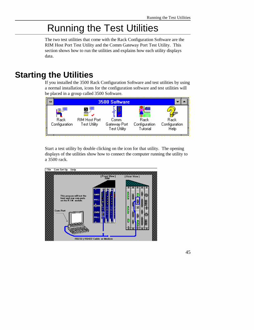
Running the Test UtilitiesThe two test utilities that come with the Rack Configuration Software are theRIM Host Port Test Utility and the Comm Gateway Port Test Utility. Thissection shows how to run the utilities and explains how each utility displaysdata.
Starting the UtilitiesIf you installed the 3500 Rack Configuration Software and test utilities by usinga normal installation, icons for the configuration software and test utilities willbe placed in a group called 3500 Software.
Start a test utility by double clicking on the icon for that utility. The openingdisplays of the utilities show how to connect the computer running the utility toa 3500 rack.
Rack Configuration and Utilities Guide
46
RIM Host Port Test UtilityThe Host ports on the Rack Interface Module and the Rack Interface I/OModule are used for communication between a computer that runs the RackConfiguration Software or the Data Acquisition/DDE Server Software and a3500 rack. The ports are also used to daisy chain up to twelve 3500 racks. TheRIM Host Port Test Utility lets you verify that the HOST ports are operatingproperly.
The options in the menu bar operate as described in the following table:
Option Name Description
FileStart Display Program Open the screen that displays the output of the
Exit End the utility.
communication port being tested.
Com Set Up Set options that control the communicationbetween the test computer and the rack.
HelpProgram Information Display a screen that explains what the utility
About
does.
Display a screen that contains copyrightinformation and the version number of the utility.

Running the Test Utilities
47
Setting Up CommunicationsThe Program Set Up display of the RIM Host Port Test Utility contains thefollowing options:
Option Name Use this option to...
Run Mode Identify the type of connection between the computer and therack. Direct: RS232 cable. Modem: modem and telephoneline.
Com Port Identify the computer port that is connected to the rack.
Baud Rate Choose the rate of communication between the computer andthe rack.
Modem Identify the type of modem connected to the test computer andthe telephone number of the rack to be tested. Use this fieldonly if you are using a modem to connect the test computer tothe rack.
Displaying Test DataTo display the output of the RIM Host Port, click on Start Display Program inthe File menu. The RIM Host Port Test Utility will continue to scan theselected 3500 racks until you click on Stop Scan. The utility displays theinformation as shown in this display.
Rack Configuration and Utilities Guide
48
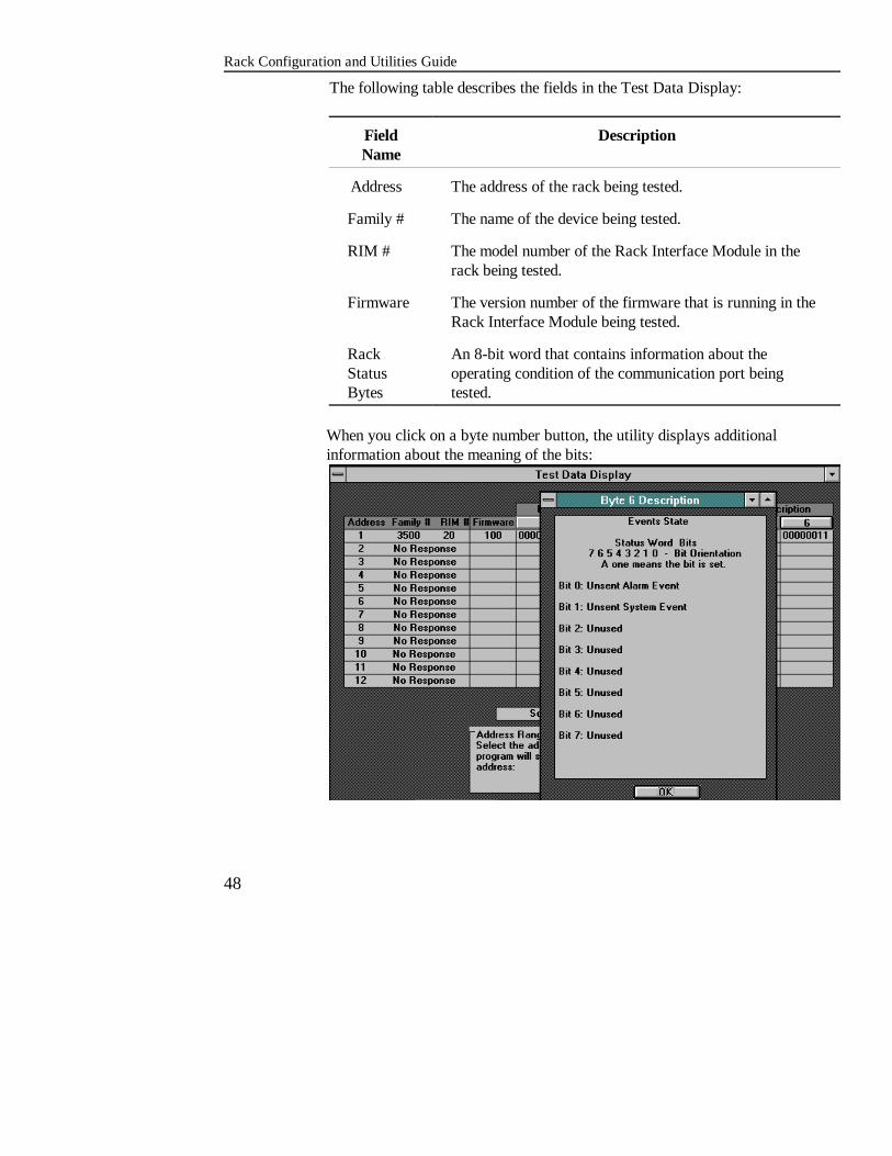
The following table describes the fields in the Test Data Display:
Field DescriptionName
Address The address of the rack being tested.
Family # The name of the device being tested.
RIM # The model number of the Rack Interface Module in therack being tested.
Firmware The version number of the firmware that is running in theRack Interface Module being tested.
Rack An 8-bit word that contains information about theStatus operating condition of the communication port beingBytes tested.
When you click on a byte number button, the utility displays additionalinformation about the meaning of the bits:

Running the Test Utilities
49
Communication Gateway Port TestThe HOST and RACK ports on the Communications Gateway I/O Module letyou connect 3500 Monitor Racks to a process control system that uses Modbuscommunication protocol. The Comm Gateway Port Test Utility lets you verifythat these ports are operating properly.
The options in the menu bar operate as described in the following table:
Option Name Description
FileScan Program Display the communication parameters of any
Data Display Display all proportional values for a monitor.
Manual Program Send messages to the Comm Gateway and display
Exit End the utility.
Comm Gateway Module in a Modbus daisy chain.
the response in hex values.
Com Set Up Set options that control the communication betweenthe test computer and the rack.
HelpProgram Information Display a screen that explains what the utility does.
About Display a screen that contains copyrightinformation and the version number of the utility.
Rack Configuration and Utilities Guide
50
Setting up CommunicationsThe Com Set Up display of the Comm Gateway Port Test Utility contains thefollowing options:
Option Name Use this option to...
CGM Port Identify the port address of the Communication GatewayAddress Module.
Comm Port Identify the computer port used to communicate between thetest computer and Comm Gateway Module.
Baud Rate Choose the rate of communication between the computer andthe Comm Gateway Module.
Parity Choose the type of communication verification contained ineach message byte. The parity setting within theCommunication Gateway Module must agree with the settingat the external device connected to the module. EachCommunication Gateway port can have a different paritysetting.
Stop Bits Set the number of bits which will be added to each 3500Communication Gateway message. Each byte within amessage will contain 1 start bit, 8 data bits, and either 1 or 2stop bits. The Stop Bits setting must agree with the setting atthe external device connected to the Communication Gateway. Each Communication Gateway port may be set up with adifferent Stop Bits setting.
If you don't know the communication settings for a Comm Gateway Module, youcan have the Scan Program under the File menu automatically detect thesesettings.
Displaying Test ResultsThe Comm Gateway Port Test Utility lets you display test results three ways: Scan Program, Data Display, and Manual Program.

Running the Test Utilities
51
The proportionalvalue as a percent offull scale.
The number labelfor the proportionalvalue.
Scan Program lets you display the communication parameters of any CommGateway Module in the Modbus daisy chain. Enter the address of the rack at theprompt.
Data Display lets you display all proportional values for a monitor as a percentof full scale.
Use the tables in the Appendix A of the Communication Gateway ModuleOperation and Maintenance manual (part number 129769-01) and the operationand maintenance manuals of the 3500 monitors to determine what proportionalvalue corresponds to the numbers on the Data Display.
Manual Program is for advanced communication diagnostics. This test lets youcompose messages to send to the Comm Gateway Module and then displays theresponse to the message in decimal values.

Rack Configuration and Utilities Guide
52
Use this portion of thedisplay to compose themessage to send to theComm Gateway Module.
The response to themessage appears here indecimal value.
Appendix A of the Communication Gateway Operation and Maintenance manual(part number 129769-01) describes the structure of the messages that arecomposed and received on the Manual Program display.
Files Used by Configuration Software
53
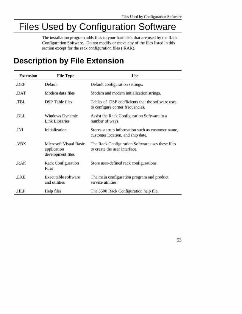
Files Used by Configuration SoftwareThe installation program adds files to your hard disk that are used by the RackConfiguration Software. Do not modify or move any of the files listed in thissection except for the rack configuration files (.RAK).
Description by File Extension
Extension File Type Use
.DEF Default Default configuration settings.
.DAT Modem data files Modem and modem initialization strings.
.TBL DSP Table files Tables of DSP coefficients that the software usesto configure corner frequencies.
.DLL Windows Dynamic Assist the Rack Configuration Software in aLink Libraries number of ways.
.INI Initialization Stores startup information such as customer name,customer location, and ship date.
.VBX Microsoft Visual Basic The Rack Configuration Software uses these filesapplication to create the user interface.development files
.RAK Rack Configuration Store user-defined rack configurations.Files
.EXE Executable software The main configuration program and productand utilities service utilities.
.HLP Help files The 3500 Rack Configuration help file.
Rack Configuration and Utilities Guide
54
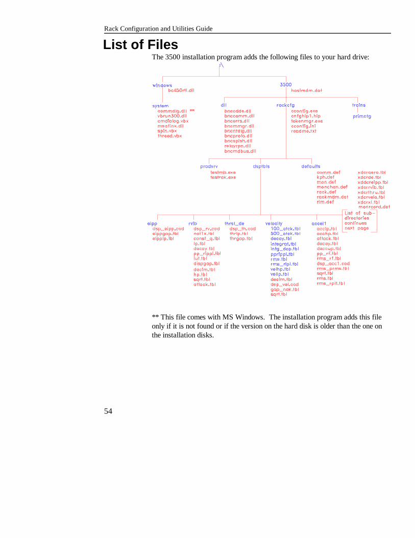
List of FilesThe 3500 installation program adds the following files to your hard drive:
** This file comes with MS Windows. The installation program adds this fileonly if it is not found or if the version on the hard disk is older than the one onthe installation disks.

Files Used by Configuration Software
55
The following diagram is a continuation of the diagram from the previous pageand shows the additional subdirectories and files that are under dsptbls.
Rack Configuration and Utilities Guide
56
Cable Part Numbers and DiagramsThis section contains information about the cables used to connect theconfiguring computer to 3500 Monitoring racks.
Cable Part NumbersCable Part Number Description
130118-XXXX-XX Host to 3500 Rack RS232 Interface Cable
132632-XXXX-XX Host to 3500 Rack RS422 Interface Cable
132633-XXXX-XX Host to 3500 Rack RS422 Interface Cable
(PVC Insulation)
(Teflon Insulation)
02290860 Host to External Modem Cable -- RS232
130119-01 Host Computer to RS232/422 ConverterCable
130120-XXXX-XX RS232/422 Converter to 3500 Rack Cable --
131106-XXXX-XX RS232/422 Converter to 3500 Rack Cable --
RS422 (PVC Insulation)
RS422 (Teflon Insulation)
130121-XX-XX RS422 Extension Cable
Cable Pin Out DiagramsThe following diagrams show the wiring for cables that are manufactured byBently Nevada:

Cable Part Numbers and Diagrams
57
Part Number 130118-XXXX-XXHost to 3500 Rack RS232 Interface Cable
Part Number 132632-XXXX-XX / 132633-XXXX-XXHost to 3500 Rack RS422 Interface Cable

Rack Configuration and Utilities Guide
58
Part Number 02290860Host to External Modem Cable -- RS232
Part Number 130119-01Host Computer to RS232/422 Convert Cable
Cable Part Numbers and Diagrams
59
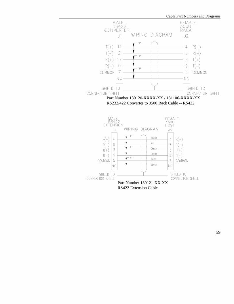
Part Number 130120-XXXX-XX / 131106-XXXX-XXRS232/422 Converter to 3500 Rack Cable -- RS422
Part Number 130121-XX-XXRS422 Extension Cable
Rack Configuration and Utilities Guide
60
Modem File Programming InformationThe Rack Configuration Software supports a number of popular modems. Tocustomize your configuration software to work with these and other modems amodem setup file has been provided in the \3500 directory calledHOSTMDM.DAT. The modem setup file contains programming informationfor all supported modems and allows one additional custom configuration. Thisfile is a simple ASCII text file that can be inspected or modified with any DOSor Windows text editor. The following entries are provided in the modem setupfile:
Setup Entry Use...
Hayes Ultra 9600 For Hayes Ultra 9600 modem using the V.32protocol.
Hayes Optima 9600 For Hayes Optima 9600 modem using the V.32protocol.
Motorola FasTalkII
Custom
For Motorola FasTalkII modem using the V.32protocol
For support of other types of modems. The entrysupplied is a copy of the Hayes Ultra 9600 modemsetup.
To support other modems, use the Custom modem type. To do this, you shouldedit the Custom entry as required and select the Custom modem type from theRemote Connect screen. Be aware that modems are highly nonstandard; gettinga new modem to work will require an intimate understanding of how to operateand program that modem.
The modem setup file consists of a "entry" name followed by 6 modem commandfields. The fields contains modem setup and control information along withmodem initialization strings. Use these guidelines when editing the fields:
C The maximum length of a line is 80 ASCII characters. Consult your modemmanual to determine the maximum initialization string length.
C The commands must be in the same order as listed in the following table.

Modem File Programming Information
61
C Fields that are not needed should be left blank but not deleted.
C Lines cannot be added or swapped.
Custom Modem Line DefinitionsModem File Entry Line Definition
1 Reset to factory default string2 Initialization string 13 Initialization string 2 *4 Dial Method (Touch Tone or Pulse)5 Connect string (the text returned when a connection is made)
6Seconds to wait for answer *
* Null if not needed
Some experimenting may be required to obtain the modem settings that give thebest results. Since the modem to modem connection baud rate is determined bythe modem, it is usually necessary to enable hardware flow control (RTS/CTS).
Many modems will automatically default to data compression. This feature cancause large "dead times" in commands and responses from the PersonalComputer and the 3500 rack. The 3500 rack looks for a specific amount ofdead time in a command to signify the end of a message. To ensure that the rackcorrectly services commands sent from the personal computer, you should eitherset the "Byte Time Out" field in the Rack Interface Module's configuration to alarge value OR setup the modem to not utilize these features.

Rack Configuration and Utilities Guide
62

Modem File Programming Information
63


