94
Part Number 129768-01 Rev. F (07/07) Operation and Maintenance Manual 3500/20 Rack Interface Module

Part Number 129768-01 Rev. F (07/07)
Operation and Maintenance Manual
3500/20 Rack Interface Module

3500/20 Rack Interface Module Operation and Maintenance Manual
ii
Copyright © 1995 Bently Nevada LLC
All rights reserved.
The information contained in this document is subject to change without notice.
The following are trademarks of General Electric Company in the United States and other countries:
Actionable Information, Actionable Information to the Right People at The Right Time, ADRE, Bently Nevada, CableLoc, Data Manager, Decision Support, DemoNet, Dynamic Data Manager, Dynamic Transmitor, Engineer Assist, FieldMonitor, FluidLoc, FlexiTIM, FlexiTAM, Helping you Protect and Manage All Your Machinery, HydroVU, Key ∅, Keyphasor, Machine Condition Manager 2000, MachineLibrary, MicroPROX, Move Data, Not People, Move Information, Not Data, Performance Manager, PROXPAC, Proximitor, REBAM, Seismoprobe, System 1, TDIXconnX, Tecknowledgy, TipLoc, TorXimitor, Transient Data Manager, Trendmaster, TrimLoc, VAM, Velomitor, Xlerometer
The following are trademarks of the legal entities cited:
Teflon® is a registered trademark of DuPont.
VelostatTM is a trademark of 3M Company.

iii
Contact Information
The following ways of contacting Bently Nevada are provided for those times when you cannot contact your local representative:
Mailing Address 1631 Bently Parkway South
Minden, Nevada USA 89423
USA
Telephone 1.775.782.3611
1.800.227.5514
Fax 1.775.215.2873
Internet www.ge-energy.com/bently

3500/20 Rack Interface Module Operation and Maintenance Manual
iv
Additional Information
Notice:
This manual does not contain all the information required to operate and maintain the product. Refer to the following manuals for other required information.
3500 Monitoring System Rack Installation and Maintenance Manual
(Part Number 129766-01)
General description of a standard system.
General description of a Triple Modular redundant (TMR) system.
Instructions for installing and removing the module from a 3500 rack.
Drawings for all cables used in the 3500 Monitoring System.
3500 Monitoring System Rack Configuration and Utilities Guide
(Part Number 129777-01)
Guidelines for using the 3500 Rack Configuration software for setting the operating parameters of the module.
Guidelines for using the 3500 test utilities to verify that the input and output terminals on the module are operating properly.
3500 Monitoring System Computer Hardware and Software Manual
(Part Number 128158-01)
Instructions for connecting the rack to 3500 host computer.
Procedures for verifying communication.
Procedures for installing software.
Guidelines for using Data Acquisition / DDE Server and Operator Display Software.
Procedures and diagrams for setting up network and remote communications.
3500 Field Wiring Diagram Package (Part Number 130432-01)
Diagrams that show how to hook up a particular transducer.
Lists of recommended wiring.

v
Product Disposal Statement
Customers and third parties, who are not member states of the European Union, who are in control of the product at the end of its life or at the end of its use, are solely responsible for the proper disposal of the product. No person, firm, corporation, association or agency that is in control of product shall dispose of it in a manner that is in violation of any applicable federal, state, local or international law. Bently Nevada LLC is not responsible for the disposal of the product at the end of its life or at the end of its use.
3500/20 Rack Interface Module Operation and Maintenance Manual
vi
Contents
1 Receiving and Handling Instructions .........................................1 1.1 Receiving Inspection ..................................................................................................1 1.2 Handling and Storing Considerations .........................................................................1 1.3 Disposal Statement ....................................................................................................2
2 General Information.....................................................................3 2.1 Triple Modular Redundant (TMR) Description ............................................................5 2.2 Statuses.....................................................................................................................5 2.3 LED Descriptions .......................................................................................................7
3 Configuration Information...........................................................8 3.1 Software Configuration Options..................................................................................8 3.1.1 Rack Interface Module Configuration Considerations .............................................8 3.1.2 Rack Interface Module Configuration......................................................................9 3.1.3 Security Options Configuration .............................................................................14 3.2 Switches...................................................................................................................15 3.2.1 Software Switches ................................................................................................15 3.2.2 Hardware Switches...............................................................................................16 3.3 Rack Reset ..............................................................................................................19 3.4 Rack Trip Multiply and Reset....................................................................................19 3.4.1 Group Trip Multiply ...............................................................................................20 3.4.2 Group Reset .........................................................................................................21 3.5 Rack Alarm Inhibit ....................................................................................................21
4 I/O Module Description ..............................................................22 4.1 Rack Interface Input/Output (I/O) Modules ...............................................................23 4.1.1 Connecting a Rack Interface I/O Module to a Host Computer...............................26 4.1.2 Daisy Chaining Rack Interface I/O Modules..........................................................33 4.1.3 Wiring Euro Style Connectors...............................................................................34 4.1.4 Cable Pin Outs .....................................................................................................35 4.2 Data Manager I/O Modules ......................................................................................42 4.2.1 Cable Pin Outs .....................................................................................................43
5 Maintenance ...............................................................................47 5.1 RIM Host Port Test Utility .........................................................................................47 5.2 Performing Firmware Upgrades ...............................................................................47 5.2.1 Installation Procedure ...........................................................................................48 5.3 Real-Time Clock Failure...........................................................................................50
6 Troubleshooting.........................................................................51 6.1 Verification ...............................................................................................................51 6.2 LED Fault Conditions ...............................................................................................52 6.3 System Event List Messages ...................................................................................54

vii
6.4 Alarm Event List Messages ..................................................................................... 69
7 Ordering Information .................................................................72
8 Specifications ............................................................................79

Section 1 - Receiving and Handling Instructions
1
1. Receiving and Handling Instructions
1.1 Receiving Inspection
Visually inspect the module for obvious shipping damage. If shipping damage is apparent, file a claim with the carrier and submit a copy to Bently Nevada Corporation.
1.2 Handling and Storing Considerations
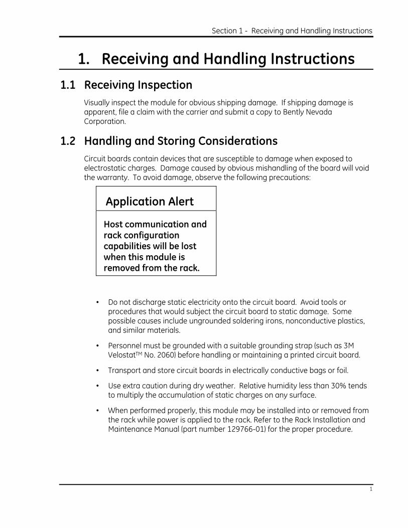
Circuit boards contain devices that are susceptible to damage when exposed to electrostatic charges. Damage caused by obvious mishandling of the board will void the warranty. To avoid damage, observe the following precautions:
Application Alert
Host communication and rack configuration capabilities will be lost when this module is removed from the rack.
• Do not discharge static electricity onto the circuit board. Avoid tools or procedures that would subject the circuit board to static damage. Some possible causes include ungrounded soldering irons, nonconductive plastics, and similar materials.
• Personnel must be grounded with a suitable grounding strap (such as 3M VelostatTM No. 2060) before handling or maintaining a printed circuit board.
• Transport and store circuit boards in electrically conductive bags or foil.
• Use extra caution during dry weather. Relative humidity less than 30% tends to multiply the accumulation of static charges on any surface.
• When performed properly, this module may be installed into or removed from the rack while power is applied to the rack. Refer to the Rack Installation and Maintenance Manual (part number 129766-01) for the proper procedure.

3500/20 Rack Interface Module Operation and Maintenance Manual
2
1.3 Disposal Statement Customers and third parties, who are not member states of the European Union, who are in control of the product at the end of its life or at the end of its use, are solely responsible for the proper disposal of the product. No person, firm, corporation, association or agency that is in control of product shall dispose of it in a manner that is in violation of any applicable federal, state, local or international law. Bently Nevada LLC is not responsible for the disposal of the product at the end of its life or at the end of its use.

Section 2 - General Information
3
2. General Information The Rack Interface Module (RIM) is the primary interface into the 3500 rack. It supports a Bently Nevada proprietary protocol used to configure the rack and retrieve machinery information. The RIM must be located in slot 1 of the rack (next to the power supplies). The RIM provides the connections needed to support current Bently Nevada Communications Processors (Transient Data Interface External (TDIX) and Dynamic Data Interface External (DDIX)). Although the RIM does provide certain functions common to the entire rack, the RIM is not part of the critical monitoring path. The RIM's operation (or non-operation) has no effect on the proper, normal operation of the overall monitoring system.

3500/20 Rack Interface Module Operation and Maintenance Manual
4
Front View Rear View
1) LEDs: Indicate the operating status of the module (See section 2.3 )
2) Hardware Switches: (See section 3.2.2 )
3) Configuration Port: Configure or retrieve machinery data from only this rack using RS-232 protocol.
4) Rack Interface I/O Module: Daisy chain or configure racks using RS-232 and RS-422 protocol (See section 4.1)
5) Data Manager I/O Module: Connect two Bently Nevada Communication Processors to the 3500 rack. (See section 4.2)

Section 2 - General Information
5
RIM Features
Contacts • Rack Reset
• Trip Multiply
• Alarm Inhibit
• OK Relay
Security
• Password
• Key Switch
Communications Ports
• Front Panel Configuration Port
• Rear Panel Host Port
• Rear Panel Rack RS-422 Port
• Data Manager Ports
Event Lists • Alarm Event List
• System Event List
2.1 Triple Modular Redundant (TMR) Description For TMR applications, the 3500 system requires a TMR version of the RIM. In addition to all the standard RIM functions, the TMR RIM also performs "monitor channel comparison." The 3500 TMR configuration executes monitoring voting using the setup specified in the monitor options. Using this method, the TMR RIM continually compares a specified output of 3 redundant monitors. If the TMR RIM detects that the information from one of those monitors is no longer equivalent (within a configured percent) to the remaining two, it will flag the monitor as being in error and place an event in the System Event List.
2.2 Statuses The Rack Interface Module returns both module and channel statuses. This section describes the available statuses and where they can be found.

3500/20 Rack Interface Module Operation and Maintenance Manual
6
Module Status
OK
This indicates if the Rack Interface Module is functioning correctly. A not OK status is returned under any of the following conditions: • Hardware Failure in the module • Communication Failure with any module • If any of the following security options have been configured and their
conditions met: Rack Address is changed while the RIM is in Run Mode. A module was inserted into or removed from the rack. The Key Switch was changed from Run to Program Mode.
• Node Voltage Failure • OK Relay coil check Failed
If the Module OK status goes not OK then the system OK Relay on the Rack Interface I/O Module will be driven not OK.
Configuration Fault
This indicates if the Rack Interface Module configuration is invalid.
Channel Status
OK
This indicates whether or not a fault has been detected on the channel or within the module. If the Channel OK status goes not OK then the system OK Relay on the Rack Interface I/O Module will be driven not OK.
The following table shows where the statuses can be found:
Statuses
Communication
Gateway
Module
Rack
Configuration
Software
Operator
Display
Software
Module OK
X
X
Module Configuration Fault
X
Channel OK
X
X

Section 2 - General Information
7
2.3 LED Descriptions The LEDs on the front panel of the Rack Interface Module indicate the operating status of the module as shown in the following figure. Refer to Section 6.2 for all of the available LED conditions.
1) OK: Indicates that the Rack Interface Module and the I/O modules are operating correctly.
2) TX/RX: Flashes at the rate that messages are sent.
3) TM: Indicates whether the rack is in the Trip Multiply mode.
4) Config OK: Indicates any of the following:
• Any module has a configuration error or is unconfigured.
• Stored configuration of the Rack Interface Module does not match the physical configuration of the rack.
• Security option condition was not met.

3500/20 Rack Interface Module Operation and Maintenance Manual
8
3. Configuration Information
This section describes how the Rack Interface Module is configured using the Rack Configuration Software. It also describes any configuration considerations associated with this module. Refer to the 3500 Monitoring System Rack Configuration and Utilities Guide and the Rack Configuration Software for the details on how to operate the software.
3.1 Software Configuration Options This section shows the configuration screens of the Rack Configuration Software that are associated with the Rack Interface Module and discusses the configuration considerations. It will show a copy of the software screen and will explain the options that are available.
3.1.1 Rack Interface Module Configuration Considerations
The Rear Port I/O option and the Power Supply option specified on the Rack Interface Module option screen must match the physical components of the system. If a configuration mismatch is found, the rack will not accept the downloaded configuration

Section 3 - Configuration Information
9
3.1.2 Rack Interface Module Configuration
This section describes the options available on the Rack Interface Module configuration screen.
Config ID
Contains a unique six-character identifier which is entered when a configuration is downloaded to the 3500 rack.
Rear Port
The port on the Rack Interface I/O Module labeled HOST that is used to connect this 3500 rack to the 3500 host computer or the 3500 rack daisy chained closer to the 3500 host computer.
I/O Option
The two types of Rack Interface I/O Modules that are available for the 3500 Monitoring System are the RS-232/RS-422 I/O Module and Modem I/O Module. The RS-232/RS-422 I/O Module contains a 9-pin host connector which contains either RS-232 or RS-422 level signals, dependent upon the position of the I/O Module switch. The Modem I/O Module has an RJ11 connector and contains an internal modem.
3500/20 Rack Interface Module Operation and Maintenance Manual
10
External Modem
The following external modems are directly supported by the Rack Interface Module when configured with an RS-232/RS-422 I/O Module:
None
Hayes Ultra 9600
Hayes Optima 9600
Motorola FasTalkII 14400
Custom
Initialization String
The command that sets up and starts the modem. If you select a modem from the list, the default initialization string will be displayed in this field. If you select Custom, enter an initialization string from the information found in the modem's documentation.
Byte Timeout
The number of byte times for which the communication line must be idle before a communication is considered complete. One byte time is a function of the baud rate selected. The range of values is 3 to 255.
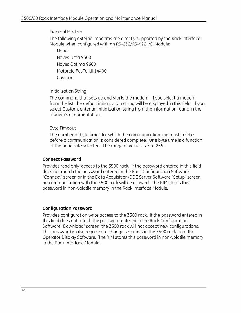
Connect Password
Provides read only-access to the 3500 rack. If the password entered in this field does not match the password entered in the Rack Configuration Software "Connect" screen or in the Data Acquisition/DDE Server Software "Setup" screen, no communication with the 3500 rack will be allowed. The RIM stores this password in non-volatile memory in the Rack Interface Module.
Configuration Password
Provides configuration write access to the 3500 rack. If the password entered in this field does not match the password entered in the Rack Configuration Software "Download" screen, the 3500 rack will not accept new configurations. This password is also required to change setpoints in the 3500 rack from the Operator Display Software. The RIM stores this password in non-volatile memory in the Rack Interface Module.

Section 3 - Configuration Information
11
Front Port
The port on the front of the Rack Interface Module labelled CONFIGURATION PORT that is primarily used to configure the 3500 rack with a personal computer. This port may also be used to retrieve machinery data for display using the Data Acquisition/DDE Server Software and the Operator Display Software. This port supports RS-232 only and provides access to only one rack.
External Modem
The following external modems are directly supported by the Rack Interface Module:
None
Hayes Ultra 9600
Hayes Optima 9600
Motorola FasTalkII 9600
Custom
Initialization String
The command that sets up and starts the modem. If you select a modem from the list, the default initialization string will be displayed in this field. If you select Custom, enter an initialization string from information found in the modem's documentation.
Byte Timeout
The number of byte times for which the communication line must be idle before a communication is considered complete. One byte time is a function of the baud rate selected. The range of values is 3 to 255.
Static Data Considerations
Each static data port can access six monitor slots in the 3500 rack. Each monitor slot in the 3500 rack is limited to 32 PPLs.
Dynamic Signal Option
Identifies which monitors provide dynamic data to the DYNAMIC connectors on the Data Manager I/O Module. This field defines how the 3500 rack will provide machinery data to the Communication Processors (TDIX or DDIX).
The following table shows the different options that are available. Keep the following in mind:

3500/20 Rack Interface Module Operation and Maintenance Manual
12
• Dynamic Port 2 is always assigned to slots 8 through 13. • If a slot contains something other than a monitor, then no data for that slot is
returned. • No data can be returned from the modules installed in slots 14 and 15.
Dynamic Signal Option
Monitors Assigned to Data
Manager Ports
Slots 2-7 assigned to Data Manager Port 1
Rack Type: Standard
Number of Communication Processors: 2
Slots 14 and 15 can not return any data since each TDIX and DDIX can only be connected to a maximum of 24 channels.
Slots 2, 4, 6, 8, 10, 12 assigned to Data
Manager Port 1
Rack Type: Standard
Number of Communication Processors: 1
Use this option when the rack is setup with multiple monitor/relay pairs.
Slots 2, 5, 8, 11 assigned to Data Manager
Port 1
Rack Type: TMR with Bussed Relay
Number of Communication Processors: 1
If a monitor is removed from slots 2, 5, 8 or 11 then no data is returned to the Communication Processor from that monitor group.
Monitor Groups
Slots 2, 6, 10 assigned to Data Manager
Port 1

Section 3 - Configuration Information
13
Rack Type: TMR with Individual Relays
Number of Communication Processors: 1
If a monitor is removed from slots 2, 6 or 10 then no data is returned to the Communication Processor from that monitor group.
Monitor Groups
Legend
Agency Approvals
The following Agency Approvals are available for the 3500 rack:
None
CSA-NRTL/C
CE Approval Select this box if the CE mark is applicable to the rack’s installation.
Rack Mounting Option
Select the type of 3500 rack that is or will be installed. Refer to the 3500 Monitoring System Rack Installation and Maintenance Manual for a description of the various mounting options.
Power Supply
The following power supplies can be installed in the 3500 rack:
Upper Position in Slot
Lower Position in Slot
No Power Supply
AC High Voltage
AC Low Voltage
DC High Voltage
No Power Supply
AC High Voltage
AC Low Voltage
DC High Voltage
Monitors
Assigned to
Data Manager
Port 2
Monitors
Assigned to Data
Manager Port 1
3500/20 Rack Interface Module Operation and Maintenance Manual
14
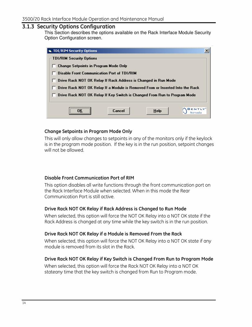
3.1.3 Security Options Configuration This Section describes the options available on the Rack Interface Module Security Option Configuration screen.
Change Setpoints in Program Mode Only
This will only allow changes to setpoints in any of the monitors only if the keylock is in the program mode position. If the key is in the run position, setpoint changes will not be allowed.
Disable Front Communication Port of RIM
This option disables all write functions through the front communication port on the Rack Interface Module when selected. When in this mode the Rear Communication Port is still active.
Drive Rack NOT OK Relay if Rack Address is Changed to Run Mode
When selected, this option will force the NOT OK Relay into a NOT OK state if the Rack Address is changed at any time while the key switch is in the run position.
Drive Rack NOT OK Relay if a Module is Removed From the Rack
When selected, this option will force the NOT OK Relay into a NOT OK state if any module is removed from its slot in the Rack.
Drive Rack NOT OK Relay if Key Switch is Changed From Run to Program Mode
When selected, this option will force the Rack NOT OK Relay into a NOT OK stateany time that the key switch is changed from Run to Program mode.

Section 3 - Configuration Information
15
3.2 Switches Switches let you control the operation of the 3500 rack and control access to the configuration of the rack. This section lists the software and hardware switches that are available for the Rack Interface Module.
3.2.1 Software Switches
The Rack Interface Module supports one software module switch Configuration Mode. The switch lets you temporarily inhibit monitor and channel functions. This switch can be set on the Software Switches screen under the Utilities Option on the main screen of the Rack Configuration Software.
No changes will take effect until the Set button is pressed.

3500/20 Rack Interface Module Operation and Maintenance Manual
16
Module Switch
Configuration Mode
This switch allows the rack to be configured. To set the rack in configuration mode, enable (⌧) this switch and set the key switch on the front of the Rack Interface Module in the PROGRAM position. When the Rack Configuration Software downloads a Rack Interface Module configuration, it will will automatically enable and disable this switch. If the connection to the rack is lost during the configuration process, use this switch to remove the module from Configuration Mode.
The module switch number is used in the Communication Gateway Module.
Module Switch Number
Switch Name
1
Configuration Mode
3.2.2 Hardware Switches
The Rack Interface Module has three hardware switches that are located on the front panel.
Key Switch
The Key Switch is used to prevent unauthorized changes to the configuration settings. When the switch is in the RUN position, the 3500 rack cannot be configured. When the switch is in the PROGRAM position, the 3500 rack can be configured and the rack continues to operate normally. By removing the key, you can lock the Rack Interface Module in the RUN or PROGRAM position.
Rack Reset
See Rack Trip Multiply and Reset.
Rack Address
The host computer uses the Rack Address to identify 3500 racks that are linked in a daisy chain. Set the rack address by using a 6-position DIP switch which provides for 63 possible addresses. All racks in a daisy chain must have a unique rack address. The following diagram and table show how to select the address 110001 (49 decimal).

Section 3 - Configuration Information
17
LSB - Least Significant Bit
MSB - Most Significant Bit
Note: The white area shows the direction of the switch.

3500/20 Rack Interface Module Operation and Maintenance Manual
18
Available Rack Address
Switch Addresses Switch Addresses Switch Addresses
MSB LSB MSB LSB MSB LSB
654321 _____ 654321 _____ 654321 _____
000000 1* 010110 22 101011 43
000001 1 010111 23 101100 44
000010 2 011000 24 101101 45
000011 3 011001 25 101110 46
000100 4 011010 26 101111 47
000101 5 011011 27 110000 48
000110 6 011100 28 110001 49
000111 7 011101 29 110010 50
001000 8 011110 30 110011 51
001001 9 011111 31 110100 52
001010 10 100000 32 110101 53
001011 11 100001 33 110110 54
001100 12 100010 34 110111 55
001101 13 100011 35 111000 56
001110 14 100100 36 111001 57
001111 15 100101 37 111010 58
010000 16 100110 38 111011 59
010001 17 100111 39 111100 60
010010 18 101000 40 111101 61
010011 19 101001 41 111110 62
010100 20 101010 42 111111 63
010101 21

Section 3 - Configuration Information
19
* The address 000000 is reserved for the host. Setting the switches to 000000 will select a Rack Address of 1 just as 000001 will.
3.3 Rack Reset
The Rack Reset function can be initiated by any of the following:
• 3500 Rack Configuration/Display Software.
• Communication Gateway.
• Hardware contact on the front of the RIM I/O module.
• Push button switch on the front of the RIM.
A rack reset will cause the RIM to send a module reset command to every module in the rack. See the Operator and Maintenance manual for the desired module to verify how the monitor will respond to this command. For example, on the 3500/42, the reset can be used to clear latched alarms.
3.4 Rack Trip Multiply and Reset
Trip Multiply is a value selected to temporarily increase the alarm setpoint values in certain monitors. In Rack Config under the Utilities menu contains an option called Rack Trip Multiply and Reset that allows a user to apply the Trip Multiply and Reset commands to various monitors from the RIM.
Trip Multiply can be invoked by:
• Shorting the TM pin to COM on the RIM I/O module.
• Selecting Enable All in the Trip Multiply screen in Rack Config. (See figure below)
• A Communication Gateway.

3500/20 Rack Interface Module Operation and Maintenance Manual
20
3.4.1 Group Trip Multiply
It is possible to group monitor channels and apply the Trip Multiply feature to a specific group of monitors channels, rather than to all monitors in the rack.
To configure a group:
1. Select a group to configure from the drop down menu labeled “Display Group”.
2. Select a monitor in the “Rack Trip Multiply and Reset” screen (see figure above).
3. A list of available channels will appear. Select the desired channel.
4. Double click the “Add Channel” button.
5. When all groups have been configured press the “Download Group” button.

Section 3 - Configuration Information
21
The Read and Write Group button will open and save the groups to/from a .rak file respectively.
To engage Trip Multiply for a group of channels:
1. Select the display group and click “Enable Group”.
2. Select the group in the communications gateway.
3.4.2 Group Reset
Just as it is possible to apply the Trip Multiply function to groups, it is possible to apply the Reset function to groups. The mechanism for Group Reset is similar to that for Group Trip Multiply, which is explained in the Group Trip Multiply section. The only difference is that the Reset Group and Reset All buttons are used instead of the Enable Group and Enable All buttons.
3.5 Rack Alarm Inhibit
Rack Alarm Inhibit is used to prevent an alarm from being declared on any monitor or relay in a 3500 rack. This feature is typically used when performing maintenance functions.
Rack Alarm Inhibit can be enabled by:
• Shorting the INHIB pin to COM on the RIM I/O module.
• Using the Alarm Inhibit option under the Utilities menu in Rack Config.
• A Communication Gateway.

3500/20 Rack Interface Module Operation and Maintenance Manual
22
4. I/O Module Description
The Rack Interface Module can use one of two I/O module types: the Rack Interface I/O Module and the Data Manager I/O Module. These I/O modules let you connect a 3500 host computer and Communication Processors (TDIX or DDIX) to a 3500 rack and daisy-chain racks together.
This section describes how to use the connectors on the I/O modules, lists what cables to use, and shows the pin outs of the cables.
Only one Rack Interface I/O Module at a time can be installed behind the Rack Interface Module (in a Rack Mount or a Panel Mount rack) or above the Rack Interface Module (in a Bulkhead rack). See Section 4.1
Also, one Data Manager I/O Module may be installed between the Power Input Modules and the Rack Interface I/O Module (in a Rack Mount or a Panel Mount rack) or above the Power Supplies between the Power Input Modules and the Rack Interface I/O Module (in a Bulkhead rack). See Section 4.2

Section 4 - I/O Module Description
23
4.1 Rack Interface Input/Output (I/O) Modules The two types of Rack Interface I/O Modules that are available for the 3500 Monitoring System are the RS-232/RS-422 I/O Module and the Modem I/O Module. The features below are common to both I/O Modules.
The Rack Interface I/O Module must be installed behind the Rack Interface Module (in a Rack Mount or Panel Mount rack) or above the Rack Interface Module (in a Bulkhead rack).
1) OK RELAY: The OK Relay is normally energized and indicates whether the 3500 Monitoring System is OK RACK RS-422: This connector is used to daisy chain to the next 3500 rack. Up to 12 racks can be daisy-chained together. Only RS-422 can be used for this connection.
2) EXTERNAL CONTACTS: • Trip Multiply • Rack Alarm Inhibit • Rack Reset

3500/20 Rack Interface Module Operation and Maintenance Manual
24
OK RELAY
The following items will cause the OK Relay to go NOT OK: • Removing the Rack Interface Module from the 3500 rack • Plugging a module into the 3500 rack (during self-test) • Transducer going not OK (except Keyphasor transducer) • Hardware failure within a module • Configuration Failure • Slot ID Failure • Any module in the 3500 rack which has detected a fault • Communication Failure with any module. • If any of the following security options have been configured and their conditions
met: Rack Address is changed while the RIM is in Run Mode. Any module is inserted or removed from the rack. The Key Switch is changed from Run Mode to Program Mode.
The following diagrams show the different ways the OK Relay can be wired:
Normally Energized
No Power With Power/ With Power/
(Shelf state) OK Condition not OK Condition
NO means Normally Open.
ARM means Armature.
NC means Normally Closed.

Section 4 - I/O Module Description
25
RACK RS-422
This connection is used to daisy chain to the next 3500 rack in the chain. The cable will go between the RACK RS-422 connector on this rack and the HOST connector on the next 3500 rack. Only RS-422 can be used for this connection. Refer to Section 4.1.2
EXTERNAL CONTACTS
These require dry contact inputs. To enable a specific function, short the desired contact to a system common (COM).
Trip Multiply (TM)
See Rack Trip Multiply and Reset section.
Rack Alarm Inhibit (INHB)
See Rack Alarm Inhibit section.
Rack Reset (RST)
See Rack Reset

3500/20 Rack Interface Module Operation and Maintenance Manual
26
4.1.1 Connecting a Rack Interface I/O Module to a Host Computer
The 3500 rack can use two types of Rack Interface I/O Modules which let you connect a host computer to a rack in a number of ways.
RS-232/RS-422 HOST Connector
This connects to the host computer using RS-232, RS-422 (with a converter) or external Modem. It is also used to connect to the previous rack in the daisy chain using RS-422 ONLY.
Use the RS-232/RS-422 switch to select whether the HOST connector uses RS-232 or RS-422 protocol.

Section 4 - I/O Module Description
27
Internal Modem Connector
This connects to the host computer over a phone line using an RJ11 compatible modular plug to link into the phone system.
Note
RS-232 signals are referenced to earth ground. This reference through the RS-232 cable has the potential of causing grounding problems. To avoid grounding problems when using RS-232 communications use serial data isolator P/N 02200633

3500/20 Rack Interface Module Operation and Maintenance Manual
28
4.1.1.1 Connecting a Rack Interface I/O Module to a Host Computer via RS-232
The communication rate is limited by the baud rate selected between the 3500 host computer and the first Rack Interface Module. The switch on the Rack Interface I/O Module connected to the 3500 host computer must be in the RS-232 position.
1) Host Computer 2) Cable 130118-XXXX-XX is available in various lengths up to 30
meters (100 ft).
Refer to Section 7 for the specific options of the cable listed above.

Section 4 - I/O Module Description
29
4.1.1.2 Additional Information for Connecting a Rack Interface I/O Module to a Host Computer via RS-232 in Intrinsically Safe Application
To avoid ground loops, the system must provide a single point ground. In Intrinsically Safe applications the 3500 Rack is floated and referenced to an intrinsically safe ground instead of earth ground while the RS-232 communications are referenced to earth ground. Therefore, to keep the rack isolated from earth ground, the installation must use a serial data isolator.
1) Host Computer 2) Cable 130118-XXXX-XX is available in various lengths up to 30
meters (100 ft). 3) Serial Data Isolator P/N 02200633
Refer to Section 7 for the specific options for the cable listed above.

3500/20 Rack Interface Module Operation and Maintenance Manual
30
4.1.1.3 Connecting a Rack Interface I/O Module to a Host Computer via RS-422
The communication rate is limited by the baud rate selected between the 3500 host computer and the first Rack Interface Module. The switch on the Rack Interface I/O Module connected to the 3500 host computer must be in the RS-422 position.
For lengths of 150 meters (500 ft) or less, use cable
130120-XXXX-XX (PVC Insulation) or cable
131106-XXXX-XX (Teflon® Insulation).
For lengths greater than 150 meters (500 ft), use one cable
130120-XXXX-XX (PVC Insulation) or cable
131106-XXXX-XX (Teflon® Insulation) along with as many
RS-422 extension cables 130121-XX-XX (150 meters (500ft)
standard length) to create a cable up to the maximum
1220 meters (4000 ft).
RS-232/RS-422 Converter
For 110 Vac use part number 02230411.
For 220 Vac use part number 02230412.
Cable 130119-01 is available in a 3 meter (10 ft) length.
Refer to Section 7 for the specific options for the cables listed above.

Section 4 - I/O Module Description
31
4.1.1.4 Connecting a Rack Interface I/O Module to a Host Computer via an External Modem
The communication rate is limited by the baud rate selected between the 3500 host computer and the first Rack Interface I/O Module. The switch on the Rack Interface I/O Module connected to the modem must be in the RS-232 position.
1) Cable 02290860 is available in 3 meter (10ft) length.
Refer to Section 7 for the specific options for the cable listed above.
3500/20 Rack Interface Module Operation and Maintenance Manual
32
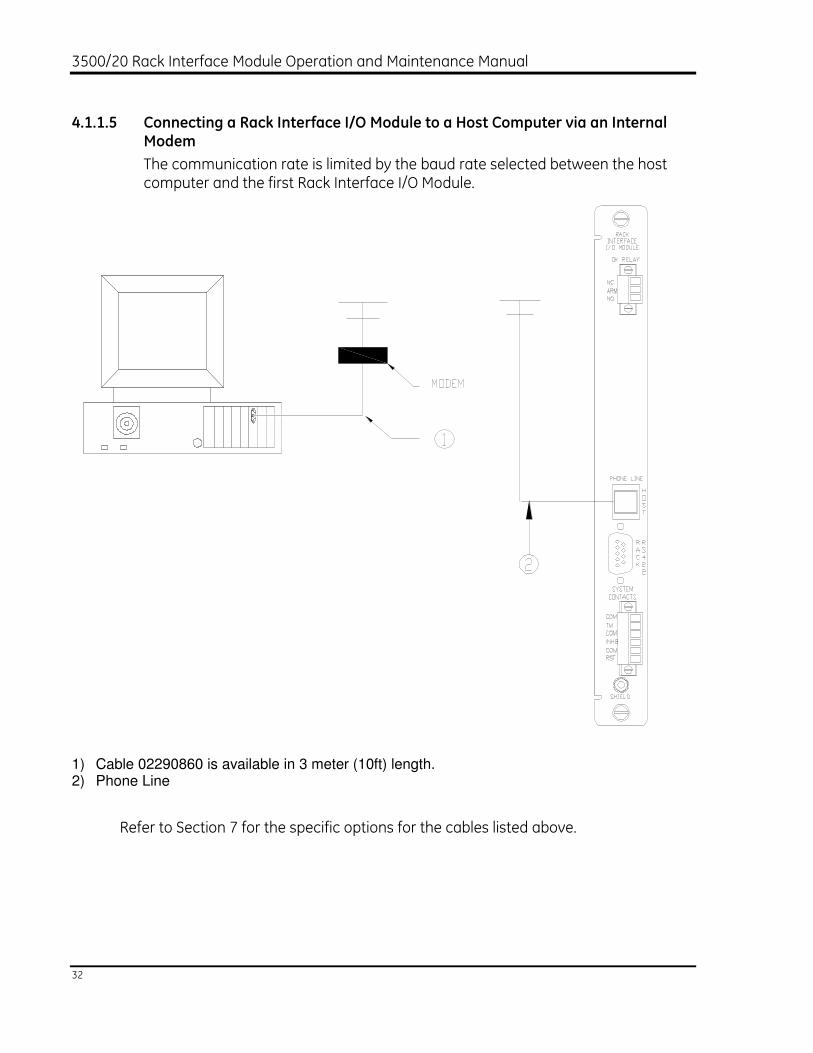
4.1.1.5 Connecting a Rack Interface I/O Module to a Host Computer via an Internal Modem
The communication rate is limited by the baud rate selected between the host computer and the first Rack Interface I/O Module.
1) Cable 02290860 is available in 3 meter (10ft) length. 2) Phone Line
Refer to Section 7 for the specific options for the cables listed above.
Section 4 - I/O Module Description
33
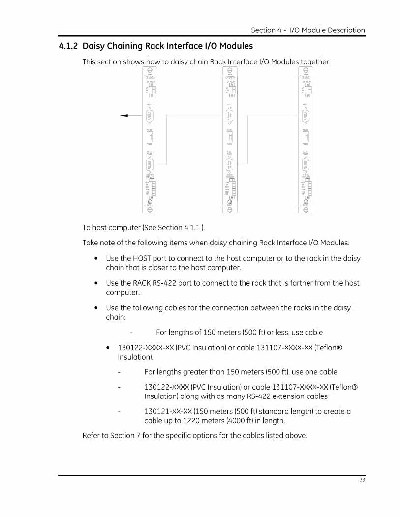
4.1.2 Daisy Chaining Rack Interface I/O Modules
This section shows how to daisy chain Rack Interface I/O Modules together.
To host computer (See Section 4.1.1 ).
Take note of the following items when daisy chaining Rack Interface I/O Modules:
• Use the HOST port to connect to the host computer or to the rack in the daisy chain that is closer to the host computer.
• Use the RACK RS-422 port to connect to the rack that is farther from the host computer.
• Use the following cables for the connection between the racks in the daisy chain:
- For lengths of 150 meters (500 ft) or less, use cable
• 130122-XXXX-XX (PVC Insulation) or cable 131107-XXXX-XX (Teflon® Insulation).
- For lengths greater than 150 meters (500 ft), use one cable
- 130122-XXXX (PVC Insulation) or cable 131107-XXXX-XX (Teflon® Insulation) along with as many RS-422 extension cables
- 130121-XX-XX (150 meters (500 ft) standard length) to create a cable up to 1220 meters (4000 ft) in length.
Refer to Section 7 for the specific options for the cables listed above.

3500/20 Rack Interface Module Operation and Maintenance Manual
34
4.1.3 Wiring Euro Style Connectors
To remove a terminal block from its base, loosen the screws attaching the terminal block to the base and then grip the block firmly and pull. Do not pull the block out by its wires because this could loosen or damage the wires or connector.
Typical I/O Module
Refer to the 3500 Field Wiring Diagram Package for the recommended wiring.
Also, do not remove more than 6 mm (0.25 inches) of insulation from the wires.

Section 4 - I/O Module Description
35
4.1.4 Cable Pin Outs
Cable Number 02290860
Host Computer (or Rack Interface Module) to External Modem Cable
Cable Number 130118-XXXX-XX
Host Computer to 3500 Rack RS-232 Interface Cable

3500/20 Rack Interface Module Operation and Maintenance Manual
36
Cable Number 132632-XXXX-XX
Host Computer (NOT 3500/95) to 3500 Rack Cable RS-422 PVC
Cable Number 132633-XXXX-XX
Host Computer (NOT 3500/95) to 3500 Rack Cable RS-422 Teflon

Section 4 - I/O Module Description
37
Cable Number 130119-01
Host Computer to RS-232/422 Converter Cable
Cable Number 130120-XXXX-XX
RS-232/422 Converter to 3500 Rack Cable (RS-422) - PVC Insulation

3500/20 Rack Interface Module Operation and Maintenance Manual
38
Cable Number 130121-XX-XX
RS-422 Extension Cable
Cable Number 130122-XXXX-XX
RS-422 3500 Rack to 3500 Rack Cable - PVC Insulation

Section 4 - I/O Module Description
39
Cable Number 131106-XXXX-XX
RS-232/422 Converter to 3500 Rack Cable (RS-422) - Teflon Insulation
Cable Number 131107-XXXX-XX
RS-422 3500 Rack to 3500 Rack Cable - Teflon Insulation

3500/20 Rack Interface Module Operation and Maintenance Manual
40
Cable Number 145164-XXXX-XX
Integrated PC Display to 3500 Rack Cable, RS-422, PVC Insulated

Section 4 - I/O Module Description
41
Cable Number 145165-XXXX-XX
Integrated PC Display to 3500 Rack Cable, RS-422, Teflon Insulated
3500/20 Rack Interface Module Operation and Maintenance Manual
42
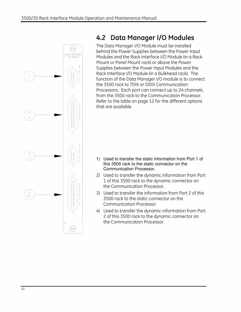
4.2 Data Manager I/O Modules The Data Manager I/O Module must be installed behind the Power Supplies between the Power Input Modules and the Rack Interface I/O Module (in a Rack Mount or Panel Mount rack) or above the Power Supplies between the Power Input Modules and the Rack Interface I/O Module (in a Bulkhead rack). The function of the Data Manager I/O module is to connect the 3500 rack to TDIX or DDIX Communication Processors. Each port can connect up to 24 channels, from the 3500 rack to the Communication Processor. Refer to the table on page 12 for the different options that are available.
1) Used to transfer the static information from Port 1 of
this 3500 rack to the static connector on the Communication Processor.
2) Used to transfer the dynamic information from Port 1 of this 3500 rack to the dynamic connector on the Communication Processor.
3) Used to transfer the information from Port 2 of this 3500 rack to the static connector on the Communication Processor.
4) Used to transfer the dynamic information from Port 2 of this 3500 rack to the dynamic connector on the Communication Processor.

Section 4 - I/O Module Description
43
Note: The 3500 Monitoring System supports the DDIX and TDIX Communication Processors.
Note: The Data Manager I/O will cease to operate if the Rack Interface Module is removed.
4.2.1 Cable Pin Outs
Cable Number 129386-01
3500 Static to TDIX Cable
Cable Number 129387-01
3500 Static to DDIX Cable

3500/20 Rack Interface Module Operation and Maintenance Manual
44
Cable Number 02290160
Dynamic Data Cable DDIX/TDIX
Note: The signals passed through cable 02290160 depend upon to which Data Manager I/O dynamic port the cable is connected and which 3500 Dynamic options are selected. The following table describes what signals are passed through Dynamic ports 1 and 2 depending on the options chosen.

Section 4 - I/O Module Description
45
Signal Pin Out Tables for Dynamic Connectors 1 and 2
Dynamic 1
Connector
Pin Number
3500 System Dynamic Signal Option
1 2 3 4
1 NONE NONE NONE NONE
7 2,1 2,1 2,1 2,1
14 2,2 2,2 2,2 2,2
18 2,3 2,3 2,3 2,3
16 2,4 2,4 2,4 2,4
11 3,1 4,1 5,1 6,1
21 3,2 4,2 5,2 6,2
25 3,3 4,3 5,3 6,3
23 3,4 4,4 5,4 6,4
2 4,1 6,1 8,1 10,1
9 4,2 6,2 8,2 10,2
4 4,3 6,3 8,3 10,3
6 4,4 6,4 8,4 10,4
20 5,1 8,1 11,1 NONE
3 5,2 8,2 11,2 NONE
19 5,3 8,3 11,3 NONE
5 5,4 8,4 11,4 NONE
24 6,1 10,1 NONE NONE
10 6,2 10,2 NONE NONE
13 6,3 10,3 NONE NONE
12 6,4 10,4 NONE NONE
15 7,1 12,1 NONE NONE
22 7,2 12,2 NONE NONE
17 7,3 12,3 NONE NONE
8 7,4 12,4 NONE NONE
Legend: [2,1] refers to Rack Slot 2, Monitor Channel 1

3500/20 Rack Interface Module Operation and Maintenance Manual
46
Dynamic 2
Connector
Pin Number
3500 System Dynamic Signal Option
1 2 3 4
1 NONE NONE NONE NONE
7 8,1 NONE NONE NONE
14 8,2 NONE NONE NONE
18 8,3 NONE NONE NONE
16 8,4 NONE NONE NONE
11 9,1 NONE NONE NONE
21 9,2 NONE NONE NONE
25 9,3 NONE NONE NONE
23 9,4 NONE NONE NONE
2 10,1 NONE NONE NONE
9 10,2 NONE NONE NONE
4 10,3 NONE NONE NONE
6 10,4 NONE NONE NONE
20 11,1 NONE NONE NONE
3 11,2 NONE NONE NONE
19 11,3 NONE NONE NONE
5 11,4 NONE NONE NONE
24 12,1 NONE NONE NONE
10 12,2 NONE NONE NONE
13 12,3 NONE NONE NONE
12 12,4 NONE NONE NONE
15 13,1 NONE NONE NONE
22 13,2 NONE NONE NONE
17 13,3 NONE NONE NONE
8 13,4 NONE NONE NONE
Legend: [2,1] refers to Rack Slot 2, Monitor Channel 1

Section 5 - Maintenance
47
5. Maintenance
This section shows how to verify that the Rack Interface Module and the I/O modules are operating correctly. When performed properly, this module may be installed into or removed from the rack while power is applied to the rack. Refer to the Rack Installation and Maintenance Manual (part number 129766-01) for the proper procedure.
5.1 RIM Host Port Test Utility Use the RIM Host Port Test Utility to verify that the HOST ports on the Rack Interface Module and the Rack Interface I/O Module are operating properly. Before running the RIM Host Port Test Utility, connect Cable 130118-XXXX-XX (Host to 3500 Rack RS-232 Interface Cable) between the Configuration Port connector on the front of the Rack Interface Module or to the HOST connector on the Rack Interface I/O Module and the computer that has the utility installed.
Refer to the 3500 Monitoring System Rack Configuration and Utilities Guide and the Rack Configuration Software for the details of this utility.
5.2 Performing Firmware Upgrades
Occasionally it may be necessary to replace the original firmware that is shipped with the 3500/20 Rack Interface Module (RIM). The following instructions describe how to remove the existing firmware and replace it with upgrade firmware. The RIM will need to be reconfigured using the 3500 Rack Configuration software after having its firmware upgraded.
The following items are required to perform a firmware upgrade to the RIM:
Large Flathead Screwdriver.
Grounding Wrist Strap.*
Small Flathead Screwdriver
Upgrade Firmware IC.*

3500/20 Rack Interface Module Operation and Maintenance Manual
48
*Refer to Section 7 (Ordering Information) for part numbers. Users may use their own grounding wrist strap.
5.2.1 Installation Procedure
Follow the steps below to complete the RIM firmware upgrade:
Ensure that the Rack Interface Module’s configuration is saved using the 3500 Rack Configuration software.
Refer to Section 1.2 (Handling and Storing Considerations) before handling the RIM or the upgrade firmware IC.
Remove the RIM from the 3500 rack.
Remove the Top Shield from the RIM.
Remove the original firmware IC from the RIM PWA.
Install the upgrade firmware IC into the socket on the RIM PWA.
Replace the RIM Top Shield.
Replace the RIM into the 3500 system.
Reconfigure the RIM using the 3500 Rack Configuration software.
The following pages contain detailed instructions for some of the steps listed above. Please review completely before proceeding.
Top Shield Removal

Section 5 - Maintenance
49
1) Top Shield.
2) Standoff.
3) Screwdriver.
Step 1. Place the large flathead screwdriver under the top shield and on the ridge of the rear standoffs and lift upward on the screwdriver to pop the cover loose from the rear standoffs.
Step 2. Move the top shield up and down to loosen it from the two front standoffs.
Original Firmware IC Removal
Step 1. Insert the small flathead screwdriver under the lip of either end of the IC. The diagram shows the approximate location of the chip to be removed, but not
necessarily its orientation.
Step 2. Gently pry up with the screwdriver to slightly lift one end of the chip from the socket. Repeat this procedure with the other end of the chip. Continue this process until the chip comes loose from the socket.

3500/20 Rack Interface Module Operation and Maintenance Manual
50
Upgrade Firmware IC Installation
Install the upgrade firmware IC into the PWA. Be sure to match the notched end of the IC to the notched end of the socket. Ensure that the IC is firmly seated in the socket.
Top Shield Replacement
Replace the top shield. Position the notch on the top shield so that it is at the top left corner of the module as shown in the diagram under “Top Shield Removal”. Align the holes in the top shield with the standoffs and press down around each standoff until they snap in place.
5.3 Real-Time Clock Failure The Real-Time Clock component on the Rack Interface Module uses an internal lithium battery that must be replaced every 3 to 10 years. The replacement interval depends on environmental conditions such as operating temperature. A discharged lithium battery may cause loss of operating information if the rack loses power. Refer to the System Event List Messages in Section 6 for the message that will be displayed when the Real-Time Clock must be replaced. Contact your nearest Bently Nevada office for instructions on how to handle this.

Section 6 - Troubleshooting
51
6. Troubleshooting
This section describes how to troubleshoot a problem with the Rack Interface Module or the I/O modules by using the information provided by the verification screen, the LEDs, the System Event List, and the Alarm Event List. You can display the verification screen and the two event lists by using the Rack Configuration Software.
6.1 Verification To perform the Rack Interface Module's verification: 1. Connect a computer running the Rack Configuration Software to the 3500 rack (if
needed). 2. Select Utilities from the main screen of the Rack Configuration Software. 3. Select Verification from the Utilities menu. 4. Select the Rack Interface Module and select the channel you want to verify. 5. Press the Verify button. 6. Select the Front Port or the Rear Port to get the status. 7. The Module OK State will show the Rack Interface Module's status and the
Channel OK State will show the channel's status.

3500/20 Rack Interface Module Operation and Maintenance Manual
52
6.2 LED Fault Conditions The following table shows how to use the LEDs to diagnose and correct problems.
OK Led
TX/RX
Condition
Solution
1 Hz
1 Hz
Rack Interface Module is not configured or in Configuration Mode.
Reconfigure the Rack Interface Module.
5 Hz
Rack Interface Module has detected an internal fault and is not OK.
Check the System Event List.
ON
Flashing
Rack Interface Module is operating correctly.
No action is required.
Not flashing
Rack Interface Module not operating correctly.
Check the System Event List.
= behavior of the LED is not related to the condition.

Section 6 - Troubleshooting
53
TM LED
Condition
Solution
ON
Rack is in Trip Multiply (due to hardware or software).
No action is required.
OFF
Rack is not in Trip Multiply.
No action is required.
Config OK LED
Condition
Solution
ON
Configuration information for every module in the rack is valid.
No action is required.
5 Hz
One of the selected security options has had its condition met.
Check the System Event List. Press the Rack Reset switch to clear.
OFF
At least one module has a configuration fault.
A non-configured active Power Supply is present in the rack.
Check System Event List for which module(s) need to be reconfigured.
OR
Reconfigure module(s) that are flashing OK and TX/RX LEDs at 1 Hz.
Remove Power Supply or change RIM configuration to include additional Power Supply.

3500/20 Rack Interface Module Operation and Maintenance Manual
54
6.3 System Event List Messages This section describes the System Event List Messages that are entered by the Rack Interface Module.
Example of a System Event List Message
Sequence
Number
Event
Information
Event
Number
Class
Event
Date
DDMMYY
Event
Time
Event
Specific
Slot
0000000123
Device Not Communicating
32
1
02/01/90
12:24:31:99
5L
Sequence Number: The number of the event in the System Event List (for example 123).
Event Information: The name of the event (for example Device Not Communicating).
Event Number: Identifies a specific event.
Class: Used to display the severity of the event. The following classes are available:
Class Value
Classification
0
1
2
3
Severe/Fatal Event
Potential Problem Event
Typical Logged Event
Reserved
Event Date: The date the event occurred.
Event Time: The time the event occurred.
Event Specific: Provides additional information for the events that use this field.

Section 6 - Troubleshooting
55
Slot: Identifies the module that the event is associated with. If a half-height module is installed in the upper slot or a full-height module is installed, the field will be 0 to 15. If a half-height module is installed in the lower slot, then the field will be 0L to 15L. For example, the module is installed in the lower position of slot 5 (5L).
The following System Event List Messages may be placed in the list by the Rack Interface Module and are listed in numerical order. If an event marked with a star (*) occurs the... • Host link on the back of the Rack Interface I/O Module supplying the message will
not communicate with the host computer • other Rack Interface Modules in the daisy chain will still be able to communicate
with the host computer • both ports of the Data Manager I/O Module will stop communicating
If you are unable to solve any of these problems, contact your nearest Bently Nevada Corporation office.
Flash Memory Failure
Event Number: 11
Event Classification: Potential Problem
Action: Replace the Rack Interface Module as soon as possible.
Real Time Clock Failure
Event Number: 12
Event Classification: Severe/Fatal Event
Action: Replace the Rack Interface Module immediately.
Internal Network Failure
Event Number: 30
Event Classification: Severe/Fatal Event
Action: Replace the Rack Interface Module immediately.
Resync Internal Network (Resynchronize Internal Network)
Event Number: 31
Event Classification: Potential Problem
Action: Check to see if one of the following components is faulty: • Rack Interface Module • Rack backplane

3500/20 Rack Interface Module Operation and Maintenance Manual
56
Device Not Communicating
Event Number: 32
Event Classification: Potential Problem
Action: Check to see if one of the following components is faulty: • Module installed in the slot
• Rack backplane
Device Is Communicating
Event Number: 33
Event Classification: Potential Problem
Action: Check to see if one of the following components is faulty: • Module installed in the slot • Rack backplane
Config Token Acquired (Configuration Token Acquired)
Event Number: 50
Event Classification: Typical logged event
Event Specific: Front,
Back,
DM1 (Data Manager port 1),
DM2 (Data Manager port 2),
ComGate (Communication Gateway)
The specified port can download configuration, change setpoints, set software switches, enable/disable Rack Alarm Inhibit, enable/disable Trip Multiply, or perform Rack Reset.
Action: No action required.

Section 6 - Troubleshooting
57
Config Token Released (Configuration Token Released)
Event Number: 51
Event Classification: Typical logged event
Event Specific: Front,
Back,
DM1 (Data Manager port 1),
DM2 (Data Manager port 2),
ComGate (Communication Gateway)
The specified port can no longer download configuration, change setpoints, set software switches, enable/disable Rack Alarm Inhibit, enable/disable Trip Multiply, or perform Rack Reset.
Action: No action required.
Config Token Expired (Configuration Token Expired)
Event Number: 52
Event Classification: Potential Problem
Action: Check to see if one of the following components is faulty: • Connection between the Rack Interface Module and the computer
running the Rack Configuration Software • Rack Interface Module • Computer running the Rack Configuration Software
Config Token Override (Configuration Token Override)
Event Number: 53
Event Classification: Typical Logged Event
Action: No action required.
Fail Relay Coil Sense
Event Number: 55
Event Classification: Potential Problem
Action: Check to see if the Rack Interface I/O Module is installed. If installed, check to see if one of the following components is faulty: • Rack Interface Module • Rack Interface I/O Module

3500/20 Rack Interface Module Operation and Maintenance Manual
58
Pass Relay Coil Sense
Event Number: 56
Event Classification: Potential Problem
Action: Check to see if the Rack Interface I/O Module is installed. If installed, check to see if one of the following components is faulty: • Rack Interface Module • Rack Interface I/O Module
I/O Module Mismatch
Event Number: 60
Event Classification: Potential Problem
Action: Verify that the Rack Interface I/O Module installed matches the Rack Interface I/O Module selected in the Rack Configuration Software. If the correct Rack Interface I/O Module is installed, there could be a fault with the installed Rack Interface I/O Module.
Rack Type Mismatch
Event Number: 61
Event Classification: Potential Problem
Action: Verify that the rack selection jumper, installed on the rack backplane, matches the rack type selected in the software. If the jumper is installed in the correct position, there could be a fault with the rack backplane.
HW Rack Alm Inh Active (Hardware Rack Alarm Inhibit Active)
Event Number: 70
Event Classification: Typical Logged Event
Action: No action required.
HW Rack Alm Inh Inactive (Hardware Rack Alarm Inhibit Inactive)
Event Number: 71
Event Classification: Typical Logged Event
Action: No action required.
Section 6 - Troubleshooting
59
HW override of SW Inh (Hardware override of Software Inhibit)
Event Number: 72
Event Classification: Typical Logged Event
Action: No action required.
HW Trip Multiply Active (Hardware Trip Multiply Active)
Event Number: 73
Event Classification: Typical Logged Event
Action: No action required.
HW Trip Mult Inactive (Hardware Trip Multiply Inactive)
Event Number: 74
Event Classification: Typical Logged Event
Action: No action required.
HW override of SW TM (Hardware override of Software Trip Multiply)
Event Number: 75
Event Classification: Typical Logged Event
Action: No action required.
HW Rack Reset Active (Hardware Rack Reset Active)
Event Number: 76
Event Classification: Typical Logged Event
Action: No action required.
HW Rack Reset Inactive (Hardware Rack Reset Inactive)
Event Number: 77
Event Classification: Typical Logged Event
Action: No action required.
SW Rack Alm Inh Active (Software Rack Alarm Inhibit Active)
Event Number: 78
Event Classification: Typical Logged Event
Action: No action required.

3500/20 Rack Interface Module Operation and Maintenance Manual
60
SW Rack Alm Inh Inactive (Software Rack Alarm Inhibit Inactive)
Event Number: 79
Event Classification: Typical Logged Event
Action: No action required.
SW Trip Multiply Active (Software Trip Multiply Active)
Event Number: 80
Event Classification: Typical Logged Event
Action: No action required.
SW Trip Mult Inactive (Software Trip Multiply Inactive)
Event Number: 81
Event Classification: Typical Logged Event
Action: No action required.
SW Rack Reset (Software Rack Reset)
Event Number: 82
Event Classification: Typical Logged Event
Action: No action required.
Rack Address changed
Event Number: 90
Event Classification: Typical Logged Event
Action: No action required.
Key Switch in Run Mode
Event Number: 91
Event Classification: Typical Logged Event
Action: No action required.
Key Switch in Prgm Mode (Key Switch in Program Mode)
Event Number: 92
Event Classification: Typical Logged Event
Action: No action required.

Section 6 - Troubleshooting
61
Fail Main Board +5V-A (Fail Main Board +5V - upper Power Supply)
Event Number: 100
Event Classification: Potential Problem
Action: Verify that noise from the power source is not causing the problem. If the problem is not caused by noise, check to see if one of the following components is faulty: • Rack Interface Module • Power Supply installed in the upper slot
Pass Main Board +5V-A (Pass Main Board +5V - upper Power Supply)
Event Number: 101
Event Classification: Potential Problem
Action: Verify that noise from the power source is not causing the problem. If the problem is not caused by noise, check to see if one of the following components is faulty: • Rack Interface Module • Power Supply installed in the upper slot
Fail Main Board +5V-B (Fail Main Board +5V - lower Power Supply)
Event Number: 102
Event Classification: Potential Problem
Action: Verify that noise from the power source is not causing the problem. If the problem is not caused by noise, check to see if one of the following components is faulty: • Rack Interface Module
• Power Supply installed in the lower slot
Pass Main Board +5V-B (Pass Main Board +5V - lower Power Supply)
Pass Main Board +5V-B
Event Number: 103
Event Classification: Potential Problem
Action: Verify that noise from the power source is not causing the problem. If the problem is not caused by noise, check to see if one of the following components is faulty: • Rack Interface Module • Power Supply installed in the lower slot

3500/20 Rack Interface Module Operation and Maintenance Manual
62
* Fail Main Board +5V-AB (Fail Main Board +5V - upper and lower Power Supplies)
Event Number: 104
Event Classification: Severe / Fatal Event
Action: Verify that noise from the power source is not causing the problem. If the problem is not caused by noise, check to see if one of the following components is faulty: • Rack Interface Module • Power Supply installed in the lower slot • Power Supply installed in the upper slot
Pass Main Board +5V-AB (Pass Main Board +5V - upper and lower Power Supplies)
Event Number: 105
Event Classification: Severe / Fatal Event
Action: Verify that noise from the power source is not causing the problem. If the problem is not caused by noise, check to see if one of the following components is faulty: • Rack Interface Module • Power Supply installed in the lower slot • Power Supply installed in the upper slot
Fail Main Board +15V-A (Fail Main Board +15V - upper Power Supply)
Event Number: 106
Event Classification: Potential Problem
Action: Verify that noise from the power source is not causing the problem. If the problem is not caused by noise, check to see if one of the following components is faulty
• Rack Interface Module
• Power Supply installed in the upper slot
Section 6 - Troubleshooting
63
Pass Main Board +15V-A (Pass Main Board +15V - upper Power Supply)
Event Number: 107
Event Classification: Potential Problem
Action: Verify that noise from the power source is not causing the problem. If the problem is not caused by noise, check to see if one of the following components is faulty: • Rack Interface Module • Power Supply installed in the upper slot
Fail Main Board +15V-B (Fail Main Board +15V - lower Power Supply)
Event Number: 108
Event Classification: Potential Problem
Action: Verify that noise from the power source is not causing the problem. If the problem is not caused by noise, check to see if one of the following components is faulty: • Rack Interface Module • Power Supply installed in the lower slot
Pass Main Board +15V-B (Pass Main Board +15V - lower Power Supply)
Event Number: 109
Event Classification: Potential Problem
Action: Verify that noise from the power source is not causing the problem. If the problem is not caused by noise, check to see if one of the following components is faulty: • Rack Interface Module • Power Supply installed in the lower slot
* Fail Main Board +15V-AB (Fail Main Board +15V - upper and lower Power Supplies)
Event Number: 110
Event Classification: Severe / Fatal Event
Action: Verify that noise from the power source is not causing the problem. If the problem is not caused by noise, check to see if one of the following components is faulty:
• Rack Interface Module
• Power Supply installed in the lower slot
• Power Supply installed in the upper slot

3500/20 Rack Interface Module Operation and Maintenance Manual
64
Pass Main Board +15V-AB (Pass Main Board +15V - upper and lower Power Supplies)
Event Number: 111
Event Classification: Severe / Fatal Event
Action: Verify that noise from the power source is not causing the problem. If the problem is not caused by noise, check to see if one of the following components is faulty: • Rack Interface Module • Power Supply installed in the lower slot • Power Supply installed in the upper slot
Fail Main Board -24V-A (Fail Main Board -24V - upper Power Supply)
Event Number: 112
Event Classification: Potential Problem
Action: Verify that noise from the power source is not causing the problem. If the problem is not caused by noise, check to see if one of the following components is faulty: • Rack Interface Module • Power Supply installed in the upper slot
Pass Main Board -24V-A (Pass Main Board -24V - upper Power Supply)
Event Number: 113
Event Classification: Potential Problem
Action: Verify that noise from the power source is not causing the problem. If the problem is not caused by noise, check to see if one of the following components is faulty: • Rack Interface Module • Power Supply installed in the upper slot
Fail Main Board -24V-B (Fail Main Board -24V -upper and lower Power Supply)
Event Number: 114
Event Classification: Potential Problem
Action: Verify that noise from the power source is not causing the problem. If the problem is not caused by noise, check to see if one of the following components is faulty: • Rack Interface Module • Power Supply installed in the lower slot
Pass Main Board -24V-B (Pass Main Board -24V - lower Power Supply)
Event Number: 115

Section 6 - Troubleshooting
65
Event Classification: Potential Problem
Action: Verify that noise from the power source is not causing the problem. If the problem is not caused by noise, check to see if one of the following components is faulty: • Rack Interface Module
• Power Supply installed in the lower slot
* Fail Main Board -24V-AB (Fail Main Board -24V - upper and lower Power Supplies)
Event Number: 116
Event Classification: Severe / Fatal Event
Action: Verify that noise from the power source is not causing the problem. If the problem is not caused by noise, check to see if one of the following components is faulty: • Rack Interface Module • Power Supply installed in the lower slot • Power Supply installed in the upper slot
Pass Main Board -24V-AB (Pass Main Board -24V - upper and lower Power Supplies)
Event Number: 117
Event Classification: Severe / Fatal Event
Action: Verify that noise from the power source is not causing the problem. If the problem is not caused by noise, check to see if one of the following components is faulty: • Rack Interface Module • Power Supply installed in the lower slot • Power Supply installed in the upper slot
Device Configured
Event Number: 300
Event Classification: Typical Logged Event
Action: No action required.
Configuration Failure
Event Number: 301
Event Classification: Severe/Fatal Event
Action: Replace the Rack Interface Module immediately.

3500/20 Rack Interface Module Operation and Maintenance Manual
66
Configuration Failure
Event Number: 301
Event Classification: Potential Problem
Action: Download a new configuration to the Rack Interface Module. If the problem still exists, replace the Rack Interface Module as soon as possible.
Module Entered Cfg Mode (Module Entered Configuration Mode)
Event Number: 302
Event Classification: Typical Logged Event
Action: No action required.
Software Switches Reset
Event Number: 305
Event Classification: Potential Problem
Action: Download the software switches to the Rack Interface Module. If the software switches are not correct, replace the Rack Interface Module as soon as possible.
Init Real Time Clock (Initialize Real Time Clock)
Event Number: 306
Event Classification: Potential Problem
Action: Replace the Rack Interface Module as soon as possible.
Monitor TMR PPL Failed (Monitor TMR Proportional value Failed)
Event Number: 310
Event Classification: Potential Problem
Action: Replace the monitor installed in the slot as soon as possible.
Monitor TMR PPL Passed (Monitor TMR Proportional value Passed)
Event Number: 311
Event Classification: Potential Problem
Action: Replace the monitor installed in the slot as soon as possible.

Section 6 - Troubleshooting
67
Module Reboot
Event Number: 320
Event Classification: Typical Logged Event
Action: No action required.
Module Removed from Rack
Event Number: 325
Event Classification: Typical Logged Event
Action: No action required.
Module Inserted in Rack
Event Number: 326
Event Classification: Typical Logged Event
Action: No action required.
Supply OK/Installed
Event Number: 330
Event Classification: Potential Problem
Action: Determine if a power supply has been installed. Verify that there is not a problem with the power source. If there are no problems with the power source, replace the power supply as soon as possible.
Supply Faulted/Removed
Event Number: 331
Event Classification: Potential Problem
Action: Determine if a power supply has been removed. Verify that there is not a problem with the power source. If there are no problems with the power source, replace the power supply as soon as possible.
Rack/RIM Powered Down (Rack or Rack Interface Module Powered Down)
Event Number: 340
Event Classification: Typical Logged Event
Action: No action required.

3500/20 Rack Interface Module Operation and Maintenance Manual
68
Rack/RIM Powered Up (Rack or Rack Interface Module Powered Up)
Event Number: 341
Event Classification: Typical Logged Event
Action: No action required.
Modem Reinitialized
Event Number: 350
Event Classification: Typical Logged Event
Action: No action required.
Device Events Lost
Event Number: 355
Event Classification: Typical Logged Event
Action: No action required.
Module Alarms Lost
Event Number: 356
Event Classification: Typical Logged Event
Action: No action required.
Rack Time Changed
Event Number: 360
Event Classification: Typical Logged Event
Action: No action required.
Module Entered Calibr. (Module Entered Calibration Mode)
Event Number: 365
Event Classification: Typical Logged Event
Action: No action required.
Module Exited Calibr. (Module Exited Calibration Mode)
Event Number: 366
Event Classification: Typical Logged Event
Action: No action required.

Section 6 - Troubleshooting
69
Config Password Changed (Configuration Password Changed)
Event Number: 400
Event Classification: Typical Logged Event
Action: No action required.
Connect Password Changed
Event Number: 401
Event Classification: Typical Logged Event
Action: No action required.
6.4 Alarm Event List Messages The following Alarm Event List Messages are returned by the different module types installed in the 3500 rack.
Communication Gateway Module
When the message will occur
Entered not OK
Left not OK
Module went not OK
Module returned to the OK state
Keyphasor Module
When the message will occur
Entered not OK
Left not OK
Module went not OK
Module returned to the OK state

3500/20 Rack Interface Module Operation and Maintenance Manual
70
Monitor Module
When the message will occur
Entered Alert / Alarm 1
Left Alert / Alarm 1
Entered Danger / Alarm 2
Left Danger / Alarm 2
Entered not OK
Left not OK
A proportional value in the channel has entered Alert / Alarm 1 and changed the channel Alert / Alarm 1 status
A proportional value in the channel has left Alert / Alarm 1 and changed the channel Alert / Alarm 1 status
A proportional value in the channel has entered Danger / Alarm 2 and changed the channel Danger / Alarm 2 status
A proportional value in the channel has left Danger / Alarm 2 and changed the channel Danger / Alarm 2 status
Module went not OK
Module returned to the OK state
Rack Interface Module
When the message will occur
Entered not OK
Left not OK
Module went not OK
Module returned to the OK state

Section 6 - Troubleshooting
71
Relay Module
When the message will occur
Entered not OK
Left not OK
Relay Activated
Relay Deactivated
Module went not OK
Module returned to the OK state
Condition for driving the relay channel met
Condition for driving the relay channel is not met anymore
3500/20 Rack Interface Module Operation and Maintenance Manual
72
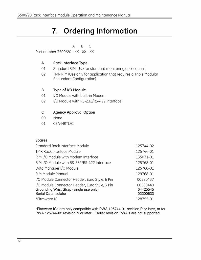
7. Ordering Information
A B C
Part number 3500/20 - XX - XX - XX
A Rack Interface Type
01 Standard RIM (Use for standard monitoring applications)
02 TMR RIM (Use only for application that requires a Triple Modular Redundant Configuration)
B Type of I/O Module
01 I/O Module with built-in Modem
02 I/O Module with RS-232/RS-422 Interface
C Agency Approval Option
00 None
01 CSA-NRTL/C
Spares
Standard Rack Interface Module 125744-02
TMR Rack Interface Module 125744-01
RIM I/O Module with Modem Interface 135031-01
RIM I/O Module with RS-232/RS-422 Interface 125768-01
Data Manager I/O Module 125760-01
RIM Module Manual 129768-01
I/O Module Connector Header, Euro Style, 6 Pin 00580437
I/O Module Connector Header, Euro Style, 3 Pin 00580440 Grounding Wrist Strap (single use only) 04425545 Serial Data Isolator 02200633
*Firmware IC 128755-01
*Firmware ICs are only compatible with PWA 125744-01 revision P or later, or for PWA 125744-02 revision N or later. Earlier revision PWA’s are not supported.

Section 7 - Ordering Information
73
Cables
RS-232 Modem cable from: 02290860
3500 Rack External Modem
Host Computer to External Modem
Host Computer to RS-232/422
Converter Cable RS-232 130119-01
TDIX - Static Data Cable 129386-01
DDIX - Static Data Cable 129387-01
DDIX/TDIX - Dynamic Data Cable 02290160
RS-232 to RS-422 Converter 110 VAC 02230411
RS-232 to RS-422 Converter 220 VAC 02230412
Host Computer to 3500 Rack Cable RS-232
A B
Part number 130118 - XXXX - XX
A Cable Length
0010 10 feet (3 meters)
0025 25 feet (7.5 meters)
0050 50 feet (15 meters)
100 100 feet (30.5 meters)
B Assembly Instructions
01 Not Assembled
02 Assembled
Host Computer to 3500 Rack Cable RS-422 PVC
A B
Part number 132632 - XXXX - XX
A Cable Length
0010 10 feet (3 meters)
0025 25 feet (7.5 meters)

3500/20 Rack Interface Module Operation and Maintenance Manual
74
0050 50 feet (15 meters)
0100 100 feet (30.5 meters)
0250 250 feet (76 meters)
500 500 feet (152 meters)
B Assembly Instructions
01 Not Assembled
02 Assembled
Host Computer to 3500 Rack Cable RS-422 Teflon
A B
Part number 132633 - XXXX - XX
A Cable Length
0010 10 feet (3 meters)
0025 25 feet (7.5 meters)
0050 50 feet (15 meters)
0100 100 feet (30.5 meters)
0250 250 feet (76 meters)
500 500 feet (152 meters)
B Assembly Instructions
01 Not Assembled
02 Assembled
RS-232/422 Converter to 3500 Rack Cable RS-422 PVC Insulated
A B
Part number 130120 - XXXX - XX
A Cable Length
0010 10 feet (3 meters)

Section 7 - Ordering Information
75
0025 25 feet (7.5 meters)
0050 50 feet (15 meters)
0100 100 feet (30.5 meters)
0250 250 feet (76 meters)
0500 500 feet (152 meters)
B Assembly Instructions
01 Not Assembled
02 Assembled
RS-232/422 Converter to 3500 Rack Cable RS-422 Teflon Insulated
A B
Part number 131106 - XXXX - XX
A Cable Length
0010 10 feet (3 meters)
0025 25 feet (7.5 meters)
0050 50 feet (15 meters)
0100 100 feet (30.5 meters)
0250 250 feet (76 meters)
0500 500 feet (152 meters)
B Assembly Instructions
01 Not Assembled
02 Assembled
3500 Rack to 3500 Rack Cable RS-422 PVC Insulated
A B
Part number 130122 - XXXX - XX
A Cable Length

3500/20 Rack Interface Module Operation and Maintenance Manual
76
0010 10 feet (3 meters)
0025 25 feet (7.5 meters)
0050 50 feet (15 meters)
0100 100 feet (30.5 meters)
0250 250 feet (76 meters)
0500 500 feet (152 meters)
B Assembly Instructions
01 Not Assembled
02 Assembled
3500 Rack to 3500 Rack Cable RS-422 Teflon Insulated
A B
Part number 131107 - XXXX - XX
A Cable Length
0010 10 feet (3 meters)
0025 25 feet (7.5 meters)
0050 50 feet (15 meters)
0100 100 feet (30.5 meters)
0250 250 feet (76 meters)
0500 500 feet (152 meters)
B Assembly Instructions
01 Not Assembled
02 Assembled

Section 7 - Ordering Information
77
Extension Cable RS-422 (Used with Cables 130120, 131106, 130122 and 131107 for lengths greater than 500 feet [152 meters])
A B
Part number 130121 - XX - XX
A Assembly Instructions
01 Not Assembled
02 Assembled
B Insulation
01 PVC Insulated
02 Teflon Insulated


Section 8 - Specifications
79
8. Specifications
INPUTS
Power Consumption: 4.75 watts maximum
Data:
Front panel: 38.4 kbaud maximum RS-232 serial communications
I/O modules: 38.4 kbaud maximum RS-232/RS-422 serial communications
56 kbaud internal modem communications
OUTPUTS
Front Panel LEDs:
OK LED: Indicates when the RIM is operating properly.
TX/RX LED: Indicates when the RIM is communicating with other modules in the 3500 rack.
TM LED: Indicates when the 3500 rack is in Trip Multiply.
CONFIG OK LED: Indicates that the 3500 rack has a valid configuration.
Data Manager I/O
Dynamic Data Port: Provides Multiplexed Buffered Transducer signals through the Data Manager I/O Module.
Output Impedance: 600 Ohms
Note: The combined parallel impedance of all loads connected to Dynamic Data Port and Buffered Transducer Outputs should be a minimum of 6K Ohms. A smaller load impedance than this could affect the accuracy of the readings.
Static Data Port: Makes Static Data available to Communication
Processor. Output Impedance: 1K Ohms
I/O Module OK Relay: Relay to indicate when the 3500 rack is operating normally or when a fault has been detected within the rack. User can select either an "OPEN" or

3500/20 Rack Interface Module Operation and Maintenance Manual
80
"CLOSED" contact to annunciate a not OK condition. This relay always operates as "Normally Energized."
OK relay (resistive load): Max switched power: DC: 120 W AC: 600 VA
Max switched current: 5 A
Min switched current: 100 mA @ 5 Vdc
Max switched voltage: DC: 30Vdc AC: 120 Vac
Contact life: 100,000 @ 5 A, 24 Vdc or 120 Vac
Environmental sealing: Epoxy sealed
Normally closed contacts: Arc suppressors are provided (250 Vrms).

Section 8 - Specifications
81

3500/20 Rack Interface Module Operation and Maintenance Manual
82
CONTROLS
Front Panel:
Rack reset button: Clears latched alarms and Timed OK Channel Defeat in the rack. Performs same function as "Rack Reset" contact on I/O module.
Address switch: Used to set the rack address. 63 possible addresses.
Configuration Keylock: Used to place 3500 rack in either RUN mode or PROGRAM mode. RUN mode allows for normal operation of the rack and locks out configuration changes. PROGRAM mode allows for normal operation of the rack and also allows for local or remote rack configuration. Key can be removed from rack in either position, allowing switch to remain in either RUN or PROGRAM positions. Locking switch in the RUN position allows you to restrict unauthorized rack configuration. Locking switch in PROGRAM position allows remote configuration of a rack at any time.
I/O Module System Contacts:
Trip multiply: Used to place 3500 rack in Trip Multiply.
Alarm inhibit: Used to inhibit all alarms in the 3500 rack.
Rack reset: Used to clear latched alarms and Timed OK Channel Defeat.
Maximum Current: <1 mA DC, Dry Contact to Common
RS-232/RS-422 Switch (RS-232/RS-422 I/O module only):
Used to select between RS-232 and RS-422 for communications with the Bently Nevada host software.
COMMUNICATIONS
Front Panel:
Communications: RS-232 only
Protocol: Bently Nevada developed
Baud rate: 38.4 kbaud maximum (auto baud capable)

Section 8 - Specifications
83
Purpose: Permits data collection and 3500 rack configuration
Cable length: 30 m (100 ft) maximum
RS-232/RS-422 I/O Module:
Communications: RS-232, RS-422, or external modem
Protocol: Bently Nevada developed
Baud rate: 38.4 kbaud maximum (auto baud capable)
Purpose: Permits data collection and 3500 rack configuration
Cable length:
RS-232: 30 m (100 ft) maximum
RS-422: 1200 m (4000 ft) maximum
Modem: Consult modem manufacturer, typical 3.0 m (10 ft)
Modem I/O Module:
Communications: Hayes AT-compatible
Protocol: Bently Nevada developed
Baud rate: Up to 56k baud
Purpose: Permits data collection and 3500 rack configuration
Cable length: 2.1 m (7 ft) maximum modem to phone jack
Rack Connector:
Communications: RS-422 only
Protocol: Bently Nevada developed
Baud rate: 38.4 kbaud maximum
Purpose: Allows multiple 3500 racks to be daisy chained together for communications with 3500 Host Software
Cable length: 1200 m (4000 ft) maximum
Data Manager I/O Module (2 sets of ports):
Communications: Bently Nevada developed
Protocol: Bently Nevada developed
Baud rate: 9600 baud only

3500/20 Rack Interface Module Operation and Maintenance Manual
84
Purpose: Permits static and dynamic data collection by Bently Nevada Transient Data Interface External or Dynamic Data Interface External Communication Processors
Cable length: 3.0 m (10 ft) maximum
ENVIRONMENTAL LIMITS
Rack Interface Module and RS232/RS422 I/O
Operating Temperature -30o C to 65o C (-22o F to 150o F)
Storage Temperature -40o C to 85o C (-40o F to 185o F)
Modem I/O Module
Operating Temperature 0o C to 50o C (32o F to 122o F)
Storage Temperature -40o C to 85o C (-40o F to 185o F)
Humidity: 95% non-condensing
CE MARK DIRECTIVES:
EMC Directives:
EN 61000-6-4:
Radiated Emissions: EN 55011, Class A
Conducted Emissions: EN 55011, Class A
EN 61000-6-2:
Electrostatic Discharge: EN 61000-4-2, Criteria B
Conducted Susceptibility: EN 61000-4-6, Criteria A
Electrical Fast Transient: EN 61000-4-4, Criteria B
Surge Capability: EN 61000-4-5, Criteria A
Magnetic Field: EN 61000-4-8, Criteria A
Power Supply Dip: EN 61000-4-11, Criteria B
EM Field Immunity: EN 61000-4-3, Criteria A

Section 8 - Specifications
85
Low Voltage Directives:
Safety Requirements: EN 61010-1
APPROVALS
CSA-NRTL/C: Class I, Division 2, Groups A through D
PHYSICAL
RIM:
Dimensions (Height x Width x Depth):
241.3 mm x 24.4 mm x 241.8 mm
(9.50 in x 0.96 in x 9.52 in)
Weight: 0.91 kg (2.0 lbs)
RS-232/RS-422 I/O:
Dimensions (Height x Width x Depth):
241.3 mm x 24.4 mm x 99.1 mm
(9.50 in x 0.96 in x 3.90 in)
Weight: 0.45 kg (1.0 lbs)
Modem I/O:
Dimensions (Height x Width x Depth):
241.3 mm x 24.4 mm x 99.1 mm
(9.50 in x 0.96 in x 3.90 in)
Weight: 0.45 kg (1.0 lbs)
Data Manager I/O:
Dimensions (Height x Width x Depth):
241.3 mm x 24.4 mm x 99.1 mm
(9.50 in x 0.96 in x 3.90 in)
Weight: 0.45 kg (1.0 lbs)

3500/20 Rack Interface Module Operation and Maintenance Manual
86
RACK SPACE REQUIREMENTS:
RIM Main Board: 1 full-height front slot
RIM I/O Modules: 1 full-height rear slot
Data Manager I/O Modules: 1 full-height rear slot


