ISSN (Print) : 232 0–3765 ISSN (Online): 2278–8875 International Journal ofAdvanced Research in Electrical, Electronics and Instrumentation Engineering Vol. 2, I ss ue 7, July 2013Copyrig ht to IJAREEIE www.ijareeie.com3471 PARTICLE SWARM OPTIMIZATION BASED DIRECT TORQUE CONTROL (DTC) OF INDUCTION MOTORT. Vamsee Kiran 1 and N. Renuka Devi 2 Associate professor, Dept. of EEE, DVR & Dr. HS MIC College of Technology, Andhra Pradesh, India 1 PG Student [P.E], Dept. of EEE , DVR & Dr. HS MIC College of Technology, Andhra Pradesh, India 2 ABSTRACT: This paper presents a new direct torque control (DTC) strategy for induction motor based on particle swarm optimization (PSO). In conventional direct torque controlled (DTC) induction motor drive, there is usually undesired torque and flux ripple. So Tuning PI parameters (Kp , Ki ) are essential to DTC system to improve the performance of the system. In this work, particle s warm optimization (PSO) is proposed to adjust the parameters (Kp , Ki ) of the speed controller in order to improve the performance of the system, and run the machine at reference speed. Keywords: Direct torque control, PI controller, particle swarm optimization. I.INTRODUCTION AC induction motors are the most common motors used in industrial motion control systems, as well as in domestic applications. Simple and rugged design, low-cost, low maintenance and direct connection to an AC power source are the main advantages of AC induction motors. Controlling the speed of an induction motor is far more difficult than controlling the speed of a DC motor since there is no linear relationship between the motor current and the resulting torque in the case of a DC motor. There are several methods to vary the speed of an induction motor over a wide range. The most modern technique is direct torque control method (DTC). The DTC offers many advantages like fast torque response, no need of coordinate transformation and less dependence on the rotor parameters. The conventional PI (proportional, integral) control method is widely used in motor control system due to the simple control structure and easiness of design. However tuning the parameters of PI controller is a difficult task. To enhance the capabilities oftraditional PI parameter tuning techniques, several intelligent approaches have been suggested such as genetic algorithms (GA) and the particle swarm optimization (PSO). Particle Swarm Optimization (PSO) is one of the modern algorithms used to solve global optimization problems. Thus, to solve an optimization problem, PSO applies a simplified social model. Compared to other methods, application ofthe PSO is simple to implement, it can quickly find a number of high quality solutions, and has stable convergence characteristics. The PSO method is an excellent optimization methodology and a promising approach for solving the optimal PI controller parameters problem. II. MATHEMATICAL MODELING OF INDUCTION MOTORThe induction motor has been modelled by using the following equations. = + (1) = + (2) + − = 0 (3) + + = 0 (4) = 3 2 2 − (5) III.THREE PHASE VOLTAGE SOURCE INVERTER
I nternational J ournal of Advanced R esearch in E lectrical, E lectronics and I nstrumentation E ngineeringVol. 2, I ssue 7, July 2013
Copyright to IJAREEIE www.ijareeie.com 3471
PARTICLE SWARM OPTIMIZATIONBASED DIRECT TORQUE CONTROL
(DTC) OF INDUCTION MOTOR T. Vamsee Kiran 1 and N. Renuka Devi 2
Associate professor, Dept. of EEE, DVR & Dr. HS MIC College of Technology, Andhra Pradesh, India 1
PG Student [P.E], Dept. of EEE, DVR & Dr. HS MIC College of Technology, Andhra Pradesh, India 2
ABSTRACT : This paper presents a new direct torque control (DTC) strategy for induction motor based on particleswarm optimization (PSO). In conventional direct torque controlled (DTC) induction motor drive, there is usuallyundesired torque and flux ripple. So Tuning PI parameters (K p, K i) are essential to DTC system to improve the
performance of the system. In this work, particle swarm optimization (PSO) is proposed to adjust the parameters (K p,K i) of the speed controller in order to improve the performance of the system, and run the machine at reference speed.
Keywords: Direct torque control, PI controller, particle swarm optimization.
I.INTRODUCTION
AC induction motors are the most common motors used in industrial motion control systems, as well as in domesticapplications. Simple and rugged design, low-cost, low maintenance and direct connection to an AC power source arethe main advantages of AC induction motors. Controlling the speed of an induction motor is far more difficult thancontrolling the speed of a DC motor since there is no linear relationship between the motor current and the resulting
torque in the case of a DC motor. There are several methods to vary the speed of an induction motor over a wide range.The most modern technique is direct torque control method (DTC). The DTC offers many advantages like fast torqueresponse, no need of coordinate transformation and less dependence on the rotor parameters. The conventional PI(proportional, integral) control method is widely used in motor control system due to the simple control structure andeasiness of design. However tuning the parameters of PI controller is a difficult task. To enhance the capabilities of traditional PI parameter tuning techniques, several intelligent approaches have been suggested such as geneticalgorithms (GA) and the particle swarm optimization (PSO).
Particle Swarm Optimization (PSO) is one of the modern algorithms used to solve global optimization problems. Thus,to solve an optimization problem, PSO applies a simplified social model. Compared to other methods, application of the PSO is simple to implement, it can quickly find a number of high quality solutions, and has stable convergencecharacteristics. The PSO method is an excellent optimization methodology and a promising approach for solving theoptimal PI controller parameters problem.
II. MATHEMATICAL MODELING OF INDUCTION MOTOR
The induction motor has been modelled by using the following equations.= + (1)
I nternational J ournal of Advanced R esearch in E lectrical, E lectronics and I nstrumentation E ngineeringVol. 2, I ssue 7, July 2013
Copyright to IJAREEIE www.ijareeie.com 3472
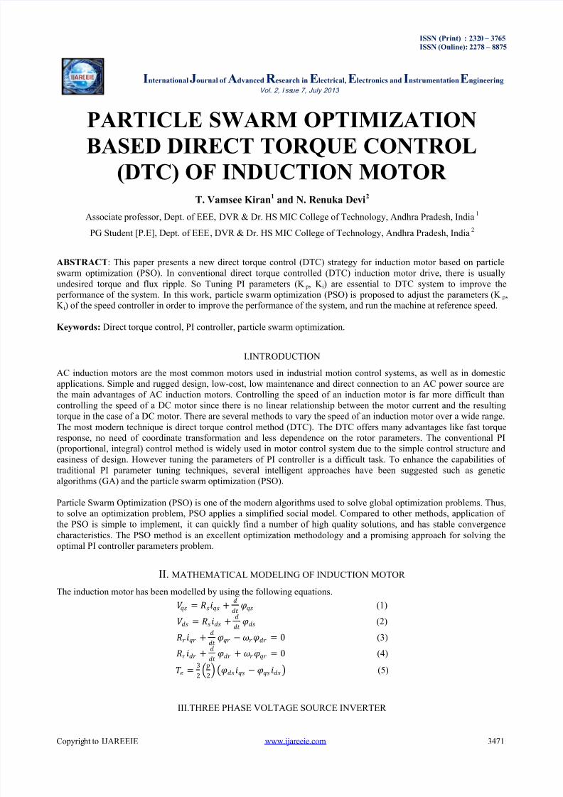
The power circuit topology of a three-phase VSI is shown in Fig.1. S1 to S6 are the six power switches that shape theoutput, which are controlled by the switching variables a, a ′, b, b ′, c and c ′.
Fig.1 Schematic diagram of two level inverter
When an upper switch is on, i.e., when a, b or c is 1, the corresponding lower transistor is switched off, i.e., thecorresponding a ′, b ′ or c ′ is 0. Therefore, the on and off states of the upper switches S 1, S 3 and S 5 can be used todetermine the output voltage. The speed and electromagnetic torque of induction motor is controlled by the selection of optimal inverter switching modes.
IV.DIRECT TORQUE CONTROL OF INDUCTION MOTOR
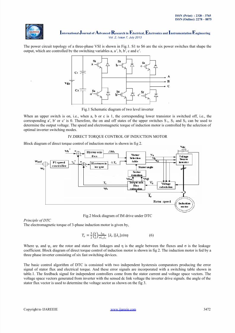
Block diagram of direct torque control of induction motor is shown in fig 2.
Fig.2 block diagram of IM drive under DTC Principle of DTC The electromagnetic torque of 3-phase induction motor is given by,
= 32 2
(6)
Where ψ r and ψ s are the rotor and stator flux linkages and η is the angle between the fluxes and σ is the leakagecoefficient. Block diagram of direct torque control of induction motor is shown in fig 2. The induction motor is fed by athree phase inverter consisting of six fast switching devices.
The basic control algorithm of DTC is consisted with two independent hysteresis comparators producing the error signal of stator flux and electrical torque. And these error signals are incorporated with a switching table shown intable.1. The feedback signal for independent controllers come from the stator current and voltage space vectors. Thevoltage space vectors generated from inverter with the sensed dc link voltage the inverter drive signals. the angle of thestator flux vector is used to determine the voltage sector as shown on the fig 3.
I nternational J ournal of Advanced R esearch in E lectrical, E lectronics and I nstrumentation E ngineeringVol. 2, I ssue 7, July 2013
Copyright to IJAREEIE www.ijareeie.com 3473
Fig.3 Relationship with voltage vectors and stator flux under DTC
Six nonzero vectors (V1 - V6) shape the axes of a hexagonal as depicted in Fig. 2, and feed electric power to the load.The angle between any adjacent two non-zero vectors is 60 degrees. Meanwhile, two zero vectors (V0 and V7) are atthe origin and apply zero voltage to the load. The eight vectors are called the basic space vectors and are denoted byV0, V1, V2, V3, V5, V6, and V7. Assuming the stator flux vector laid on the sector 1 of the d-q plane, V1, V2, V6could be selected to increase the stator flux vectors. Conversely, V3, V4, V5 could be selected to decrease the stator flux vector. The zero (null) voltage vectors does not effect on the stator flux vector. Voltage vectors are selected tocontrol the torque also. In general, V2 and V3 vectors can be selected to increase the torque and V5, V6, V0 vectorswill decrease the torque. Table 1 shows voltage vector selection according to stator flux and torque errors.
Table.1 Selection table of voltage vector
S Ψ
S T
S e c t o r
I S e c t o r
I I
S e c t o r
I I I
S e c t o r
I V
S e c t o r
V
S e c t o r
V I
1
1 V2 V3 V4 V5 V6 V1
0 V7 V0 V7 V0 V7 V0
-1 V6 V1 V2 V3 V4 V5
0
1 V3 V4 V5 V6 V1 V2
0 V0 V7 V0 V7 V0 V7
-1 V5 V6 V1 V2 V3 V4
V. PARTICLE SWARM OPTIMIZATION
Particle swarm optimization is a heuristic global optimization method put forward originally by Doctor Kennedy andEberhart in 1995. It is developed from swarm intelligence and is based on the research of bird and fish flock movement
behaviour.
PSO has two primary operators; velocity and position update. In this paper the main objective of PSO is minimizationof speed error. Fig.4 shows the block diagram for PI controller and the corresponding objective function is as shown inequation (7) and (8).
I nternational J ournal of Advanced R esearch in E lectrical, E lectronics and I nstrumentation E ngineeringVol. 2, I ssue 7, July 2013
Copyright to IJAREEIE www.ijareeie.com 3474
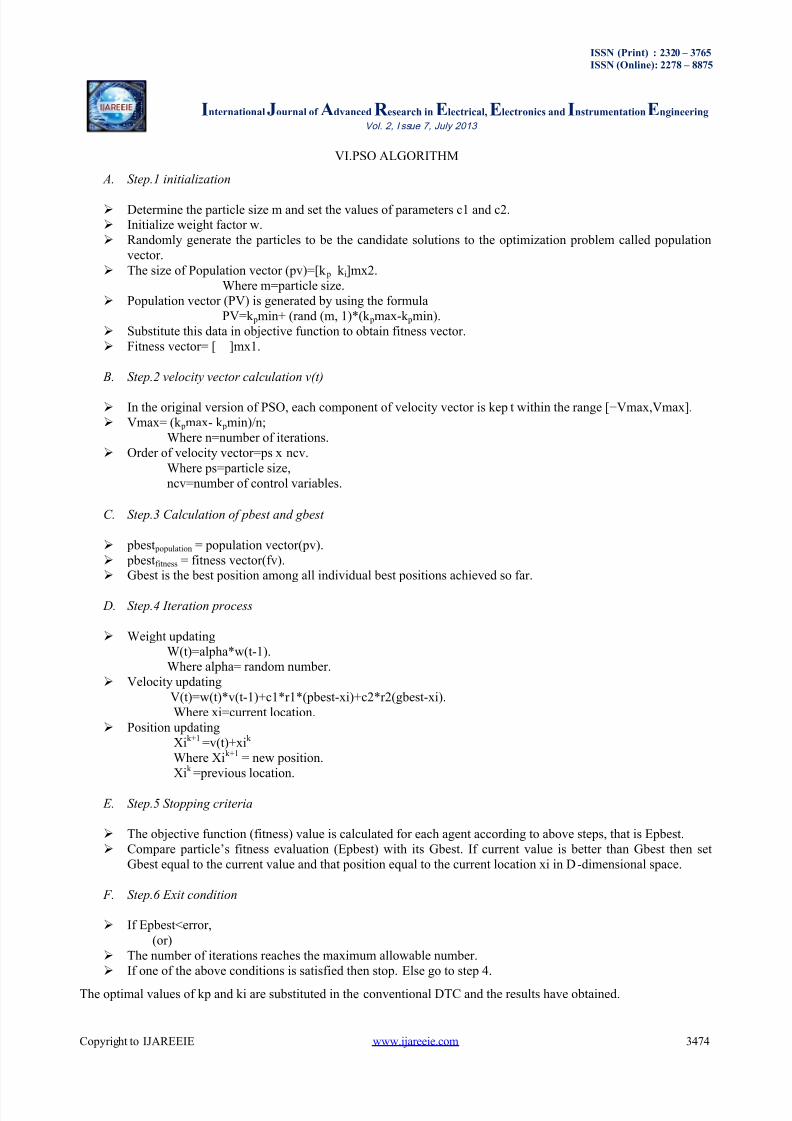
VI.PSO ALGORITHM
A. Step.1 initialization
Determine the particle size m and set the values of parameters c1 and c2. Initialize weight factor w. Randomly generate the particles to be the candidate solutions to the optimization problem called population
vector. The size of Population vector (pv)=[k p k i]mx2.
Where m=particle size. Population vector (PV) is generated by using the formula
PV=k pmin+ (rand (m, 1)*(k pmax-k pmin). Substitute this data in objective function to obtain fitness vector. Fitness vector= [ ]mx1.
B. Step.2 velocity vector calculation v(t)
In the original version of PSO, each component of velocity vector is kep t within the range [−Vmax,Vmax]. Vmax= (k pmax- k pmin)/n;
Where n=number of iterations. Order of velocity vector=ps x ncv.
Where ps=particle size,ncv=number of control variables.
C. Step.3 Calculation of pbest and gbest
pbest population = population vector(pv). pbest fitness = fitness vector(fv). Gbest is the best position among all individual best positions achieved so far.
D. Step.4 Iteration process
Weight updatingW(t)=alpha*w(t-1).Where alpha= random number.
Position updatingXi k+1 =v(t)+xi k Where Xi k+1 = new position.Xi k =previous location.
E. Step.5 Stopping criteria
The objective function (fitness) value is calculated for each agent according to above steps, that is Epbest. Compare particle’s fitness evaluation (Epbest) with its Gbest. If current value is better than Gbest then set
Gbest equal to the current value and that position equal to the current location xi in D -dimensional space.
F. Step.6 Exit condition
If Epbest<error,(or)
The number of iterations reaches the maximum allowable number. If one of the above conditions is satisfied then stop. Else go to step 4.
The optimal values of kp and ki are substituted in the conventional DTC and the results have obtained.
I nternational J ournal of Advanced R esearch in E lectrical, E lectronics and I nstrumentation E ngineeringVol. 2, I ssue 7, July 2013
Copyright to IJAREEIE www.ijareeie.com 3475
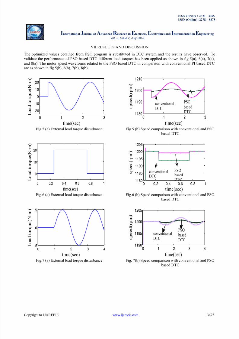
VII.RESULTS AND DISCUSSION
The optimized values obtained from PSO program is substituted in DTC system and the results have observed. To
validate the performance of PSO based DTC different load torques has been applied as shown in fig 5(a), 6(a), 7(a),and 8(a). The motor speed waveforms related to the PSO based DTC in comparison with conventional PI based DTCare as shown in fig 5(b), 6(b), 7(b), 8(b).
Fig.5 (a) External load torque disturbance
Fig.6 (a) External load torque disturbance
Fig.7 (a) External load torque disturbance
Fig.5 (b) Speed comparison with conventional and PSO based DTC
Fig.6 (b) Speed comparison with conventional and PSO based DTC
Fig. 7(b) Speed comparison with conventional and PSO based DTC
I nternational J ournal of Advanced R esearch in E lectrical, E lectronics and I nstrumentation E ngineeringVol. 2, I ssue 7, July 2013
Copyright to IJAREEIE www.ijareeie.com 3476
Fig.7 (a) External load torque disturbance Fig.8 (b) Speed comparison with conventionalAnd PSO based DTC
It has been observed that the speed performance of a PSO based DTC is better when compared with the conventionalDTC.
VIII.CONCLUSIONS
In this paper, the proposed PSO based DTC control scheme has been implemented. The simulation results of thismethod have improved the speed performance of the induction motor irrespective of the load torque fluctuations. The
proposed PSO method has optimized the parameters of PI controller by minimizing the speed error. It can be concludedthat the PSO algorithm employed in DTC of induction motor has resulted in the optimal generation of k p, k i values.This proposed method has finally improved the dynamic speed behaviour of the induction motor when compared withthat of a Conventional PI controller based DTC of Induction motor.
REFERENCES
[1] Bo zhou, “Application of particle swarm optimization on DTC for induction motor”, IEEE DOI 10.1109/ICNC.2008.300[2] O.S. EI-Laban , H.A. Abdel Fattah, H.M.Emara, and A.F.S akr, “partical swarm optimized direct torque control of induction motors”. IEEE
Trans, 2006.[3] M. A. Abido, “optimal power flow using particle swarm optimization”, electrical power and energy system vol.24,pp. 563 -571,2002[4] Ioan Cristian Treela. “the particle swarm optimization algorithm”: convergence analysis and parameter selection. Information processing Lett.,
85(2003)317- 325.[5] Ahmud Iwan Solihin, Lee Fook Tack and Moey LeapKean. “Tuning of PID controller using particle swarm optimization” (PSO). 2011 .[6] Hassan Farhan Rashag, S.P.Koh, Ahmed N. Abdalla, nadia M. L. Tan, K. H. Chong and S. K. Tiong, “ DTC torque ripple mi nimization
based on PSO- PID controller”. Scientific research and Essay., vol. 7,pp(15), 1564-1572, 2012.[7] J. Kennedy and R. C. Eberh art, “ Particle Swarm Optimization,” in Proc. IEEE Int. of Neural Networks, Piscataway, NJ, USA, 1942-1948,
1995.[8] R. C. Eberhart and Y.Shi,“Guest editorial,” IEEE Trans. Evol. Comput. (Special Issue on Particle Swarm Optmization), vol. 8, pp. 201-
203 no. 3, Jun. 2004.[9] Eberhart R C, Shi Y. (1998). Comparison between genetic algorithms and Particle Swarm Optimization. Porto VW. Saravanan N,Waagen D,
et al.Evolutionary Programming VII.[S.l.]:Springer,1998:611-616.
BIOGRAPHIES
0 0.2 0.4 0.6 0.8 1
0
5
10
time(sec)
L o a d
t o r q u e (
N - m
)
0 0.2 0.4 0.6 0.8 11180
1190
1200
1210
time(sec)
s p e e d
( r p m
)
conventionalDTC
PSO basedDTC
N. Renuka Devi pursuing M-Tech (power electronics) in DVR & Dr. HS MIC College of Technology. Received B-tech degree in electrical engineering from Prasad V potluri Siddharthainstitute of technology, Vijayawada in the year 2011.
T. Vamsee Kiran is graduated from Bapatla Engineering College in the year 2000 and M.E inApplied Electronics from PSG College of Technology, Coimbatore in the year 2002. He workedin Sir C.R. Reddy College of Engineering, K.L.College of Engineering and is presently workingas Associate Professor in DVR & Dr. HS MIC College of Technology, and has got 12 years of teaching experience. He has submitted his Ph.D thesis in JNTU College of Engineering,Hyderabad. He presented papers in National, international Conferences and International
Journals. His research interests include Power Electronics Drives and Multilevel Inverters.