BH-USA Rotating PWC Lift Guide Appendix C—1 800-259-8715 98551PR Rvsd. 07/2015 BH-USA assumes no responsibility or liability for installations and/or improper use of the equipment. is guide is intended to be used as a reference and general guideline only. BH-USA is not responsible for the design, construction or installation of docks, piers or lifts. 360° ROTATING PERSONAL WATERCRAFT (PWC) LIFT GUIDE Rvsd. 7-2015 THIS GUIDE IS INTENDED FOR THE END USER, and contains general information for installing a BH-USA PWC 360° Lift onto a dock/pier . is is not a construction manual, BH-USA is a manufacturer of hoists and lift components and not an installer.
BH-USA assumes no responsibility or liability for installations and/or improper use of the equipment. This guide is intended to be used as a reference and general guideline only. BH-USA is not responsiblefor the design, construction or installation of docks, piers or lifts.
360° ROTATING PERSONAL WATERCRAFT(PWC) LIFT GUIDE
Rvsd. 7-2015THIS GUIDE IS INTENDED FOR THE END USER,
and contains general information for installing a BH-USA PWC 360° Lift onto adock/pier . This is not a construction manual, BH-USA is a manufacturer of hoists and
lift components and not an installer.
BH-USA WARRANTY INFORMATION
• GEARPLATE ASSEMBLIES (GPAS) - LIFETIME
• ENCLOSED GEARS - TWO YEARS
• MOTORS - ONE YEAR
• SWITCH AND GFCI - 30 DAYS
The following warranty applies to all components and hoists manufactured by BH-USA. Warranty applies to manufacturing defects and/or failures due to designor fabrication. Replacement parts, a repaired unit, or a new unit will be suppliedat no charge at the discretion of BH-USA. This does NOT include labor or freight.
THE FOLLOWING ARE NOT WARRANTABLE BUT ARE MANUFACTURED ANDREGULATED BY SPECIFIC INDUSTRY STANDARDS.
SLINGS AND CRADLES
STRUCTURAL STEEL
FASTENERS
CABLE AND RIGGING
MACHINED PARTS, I.E. GEARSWarranty is void if unit is improperly installed, maintained, or greased or alterations are made to theoriginal manufacturer’s design. Warranty is predicated on the equipment being inspected and serviced on an annual basis by a qualifiedtechnician. A record of inspection is required with any warranty request. Warranty applies to original owner. Warranty is VOID if transfer of ownership.
BH-USA RETURNS2368 FM 2087N LONGVIEW, TX75603
Call prior to returning equipment for RMA (Returned Merchandise Authorization).All Returns must have RMA number clearly listed on return box.We are not responsible for damages incurred in shipment.Customer is responsible for return shipping costs.Once item is received, BH-USA will deem item returned warrantable within two weeks.BH-USA reserves the right to determine whether warranted items will be repaired or replaced.
WHILE EVERY CARE HAS BEEN TAKEN TO AVOID MISTAKES, BH-USA WILL NOT ACCEPT LIABILITY FOR ANY ERRORS, MISPRINTS, TYPOGRAPHICAL ERRORS, OMISSIONS OR MISINTERPRETATIONS OF THE BH-USA OVERHEAD LIFT GUIDE - THE BH-USA EQUIPMENT GUIDE.
* See BH-USA Limited Warranty Information on the inside back cover of this publication.
WARRANTY PROCEDUREPlease review thispublication beforeattempting a returnto BH-USA forwarrantyconsideration.
DO NOT return theproduct to the storewhere it waspurchased or to theinstaller/dealer.
CallBH-USACUSTOMERSUPPORT800-259-8715
Returnedmerchandise mustbe sent via groundand not through theU.S. Postal Service.
Warranties dependupon an annualprofessionalinspection by aqualified technician.
Although BH-USAdoes not endorseany builder orinstaller, a BUILDER LOCATORis provided on theBH-USA website,listing builder’sfound to be reliableand knowledgeableusing BH-USAequipment.BH-USA.COM/BUILDER-LOCATOR
CAUTION… BH-USA IS A MANUFACTURERONLYWhile there aremany notable andqualifiedprofessional liftinstallers, there is nogoverning orlicensing agency thatregulatesinstallations.BH-USA assumes noliability for theinstallation of yourlift.
End users shouldfamiliarize themselveswith the basics ofpersonal watercraftlifts and their design,to enable them todetermine if a properinstallation has beencompleted. BH-USA warrantiesPWC lift equipmentbased on properinstallation andmaintenance and thestrict following of thisguides.
APPROX. WEIGHTSFuel Weight= Gallons x 6 lb
Approximate weightsof many personal wa-tercraft lifts can befound on the NADAwebsite at:WWW.NADAGUIDES.COM/BOATS/PERSONAL-WATER-CRAFT
BH-USA PWC LIFT INSTALLATION GUIDELINES
BEFORE FIRST USE - UNPACK AND CHECK EQUIPMENTA handy item list is printed at the back of this publication. It includes everything that should be in theBH-USA PWC Box.
CHOOSING THE LIFT LOCATION AND INSTALLATIONIn order to support both the weight of the lift, and PWC to be picked up, choose a location that isstructurally sound.
IMPORTANT: The mounting structure must be structurally sound to support theweight of the lift and the intended PWC.
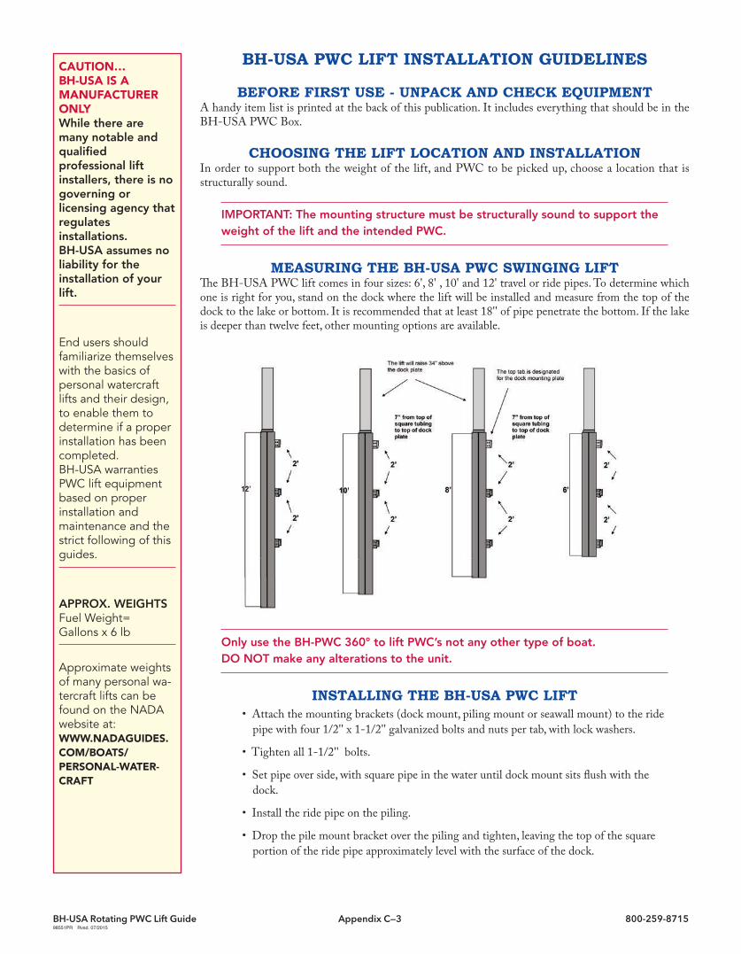
MEASURING THE BH-USA PWC SWINGING LIFTThe BH-USA PWC lift comes in four sizes: 6', 8' , 10' and 12' travel or ride pipes. To determine whichone is right for you, stand on the dock where the lift will be installed and measure from the top of thedock to the lake or bottom. It is recommended that at least 18'' of pipe penetrate the bottom. If the lakeis deeper than twelve feet, other mounting options are available.
Only use the BH-PWC 360° to lift PWC’s not any other type of boat. DO NOT make any alterations to the unit.
INSTALLING THE BH-USA PWC LIFT• Attach the mounting brackets (dock mount, piling mount or seawall mount) to the ride
pipe with four 1/2'' x 1-1/2'' galvanized bolts and nuts per tab, with lock washers.
• Tighten all 1-1/2'' bolts.
• Set pipe over side, with square pipe in the water until dock mount sits flush with thedock.
• Install the ride pipe on the piling.
• Drop the pile mount bracket over the piling and tighten, leaving the top of the squareportion of the ride pipe approximately level with the surface of the dock.
Launching jet skis orany other personalwatercraft is easierwith a PWC lift. TheBH-USA 360° PWClift has a straight linelifting capacity of1250 lbs., and has afully rotationalcradle that makeslaunching andmaintaining yourPWC easy and safe.
The cradle travels ona galvanized ridepipe that stays in thewater. Thiseliminates the needfor an mast in theair. The BH-USA 360°PWC lift is perfectfor mounting insidea boat house, undera canopy, or out inthe open. It can bemounted straight tothe dock or on apiling.
The innovative dockmount and pilemount installation iseasy and reduces theamount of stress onthe piling or dock.
The BH-USA PWC lifthas the addedadvantage of beingpowered by the BH-USA Hoist —
• Ensure that the pipe is plumb both fore to aft and side to side.
CAUTION: The ride pipe must extend 2 feet below the surface of the water atthe lowest expected water level.
• Slide the ½'' x -3-½’’ round bearing ring over the round top of the ride pipe until itrests on the square tube portion of the ride pipe. Failure to do this can result inserious damage to the lift.
• Install the main housing by sliding it over the rotate tube and letting it sit on the dock.
• Liberally grease the round portion of the ride pipe to assure smooth and easy operation.
• Lay out the winch components and the motor mount pipe.
• Mount the motor, large pulley and belt on the winch unit using supplied hardware,making sure to properly align the motor and winch pulleys
• Insert cable in the hole immediately next to the drum center, on the gear side, and pullout about two feet. Insert cable into the cable clamp so approximately ¼'' of the cableextends past the end of the clamp.
CAUTION: It is important to ensure that the cable clamp is tight against the sideof the cable drum on the winch. Slide the motor mount pipe/winch assemblyonto the rotate tube/ride pipe until it contacts the bearing ring. Rotate theassembly several times to ensure even distribution of the grease. Make sure thecable comes over the drum, so the running line is on the outside of the assembly,away from the motor mount pipe. Uncoil the cable and attach the free end to thecradle lifting tab. Connect the motor to the power source. Wind the cable tightlyonto the drum, while keeping tension on the cable until the slack is taken up andthe weight of the cradle is on the cable. The cable MUST wrap in the correct direction on the drum or contact with thetab on the motor mount pipe will occur.
• Measure the width of the watercraft and divide by two. Measuring out from the guidepost stanchions, mark the center line of the watercraft on the cradle. This will be thecentering mark for the bunk boards. For PWC’s, mount each bunk 6'' to 8'' from thecenter line, using the bunk board brackets and bolts supplied. Make sure the bunk boardsare resting on a flat part of the PWC, that the PWC is not touching the steel at anypoint and that the boat is snug against the guide posts.
• When operating the lift, make sure that the cable is wrapping on the outboard side ofthe drum and not wrapping over itself, until each layer on the drum is completely full.
• Grease the zerk fittings with BH-USA Grease*, on the winch unit; they are near the topof the gear, under the motor mount. Rotate the cradle over the water, lower and raise thelift several times to be sure it is operating correctly. Grease the zerk fittings again. Thegears must be well-greased at all times. On rotating models, raise lift to the point it willclear the dock or seawall and rotate it back and forth several times to check for properoperation. To increase the life of your lift, grease all zerk fittings every three months.
• The cable must be kept tight with no slack. The cradle must never rest on the bottom,this could allow the cable to become slack and overwrap itself. This can cause the cable tofray and create an unsafe condition when operating the lift. If the cradle is rested on thedock, caution should be taken to ensure no slack is allowed in the cable.
*BH-USA Grease can be ordered online at BH-USA.com.
BH-USA PWC LIFT INSTALLATION GUIDELINES
BH-USA PWC LIFT INSTALLATION GUIDELINES
• Install posts over guide stanchions
• Install the white vinyl motor/gear cover.
WARNING: Unplug lift and stow cord prior to rotating!Any BH-USA Rotating Lift is intended to rotate 180 degrees in either direction. Itis not intended to rotate past 180 degrees. Failure to follow this warning may result in the lift cord twisting around the lift with serious consequences. Cautionmust be exercised when rotating the lift!
BH-USA PWC LIFT MOUNTING GUIDEDOCK MOUNT Option A - This option allows for the ride pipe to actually penetrate the ground belowthe deck. It is a strong installation which offers minimal stress on the dock. The ride pipe is used as themain support and is driven approximately 18'' into the ground if a structure is not available behind the lift.DOCK MOUNT Option B - With this option the ride pipe is still the main support and is driven intothe ground approximately 18'' with a piling clamp attached to an existing piling for added support. It isthe strongest mount.
Doesn’t require aspecially fortifieddock construction
Powered by the BH-USA Hoist
Backed by the BH-USA LifetimeWarranty
1250 lbs. StraightLine Lifting Capacity
Available in 6', 8',10’and 12’ travel/ridepipes
6ft, 8ft, 10ft and 12ft drivepipes are measured from thetop to bottom of the squaretubing only.
The ground must be hard,not mud and must haveplenty of surface behind it.
18'' minimum 18'' minimum
ROTATE TUBE Dock Mount Dimensions24” W x 3” H x 7”D
3 x 4 Tab and Gusset on Face
ROTATE TUBE
RIDE
PIP
E
CAUTION: Bearing Ring must be installed to avoid serious damageto the BH-USA PWC Lift.
DOCK MOUNT Option C - If the ride pipe does not reach the ground, a piece of 2'' galvanized pipe (notincluded) can be used to extend the pipe so that is can be driven into the ground. Slide the ride pipe overthe top of the pipe. Use dock mount for support. Use of a space is recommended and should be welded tothe bottom of the square tubing. Pipe must be driven into bedrock or hard surface.
DOCK MOUNT Option D - The lift can also mount on top of the dock piling. Use the dock plate and thepiling bracket that is included, mount piling bracket to the lowest tab for support. An optional piling bracketcan be ordered at BH-USA.COM to add even more support to the dock.
Installation Tabs - Typical installations will use two of the three available tabs. The top tab is used forthe dock mount bracket. The pile mount will be placed on one of the two lower tabs depending on thestructure and installation for this dock. Some installations only require on tab (dock mount) to be used ifthe drive pipe can penetrate the lake bottom by at least 18''. There are three tabs welded to the main drivepipe, one tab welded to the dock mount and one tab welded to the included pile mount clamp. The tabsbolt together to support the drive pipe on the dock.
Fasteners are NOT to scale and will require measuring.
Doesn’t require aspecially fortifieddock construction
Powered by the BH-USA Hoist
Backed by the BH-USA LifetimeWarranty
1,250 lbs. StraightLine Lifting Capacity
Available in 6', 8'and 10’ travel/ridepipes
Dock Mount Plate - The BH-USA PWC Lift comes with one dock mount plate. Install the dock mountplate first on the dock. Remember to leave room for the lift to rotate on either side, the recommendationis at least five feet. Use the four 1/2'' bolts supplied with the lift and back them with washers. It is notrecommended to lag bolt the four outside points. The two large center points can be lag-bolted using thelarge bolts supplied.BH-USA fasteners for the dock plate will work on typical dock construction. There is a possibility that adock might require longer bolts than the ones supplied with your lift. When purchasing additional, longerbolts hot dipped galvanized bolts are strongly recommended.
Fasteners are NOT to scale and will require measuring.
Ride Pipe - Set the ride pipe into the water and bolt to theinstalled dock plate using four 1/2'' x 1-1/2'' bolts. Secure the lowerportion of the drive pipe to the support structure of the dock usingthe included piling clamp If the lower part of the drive pipe canpenetrate a minimum 12'' into the lake bottom, the lower clampmay not actually be needed. Depending on the softness of the lakebottom, and the depth of the pole into the lake bottom, insufficientsupport for leveraging the lift could be a problem. BH-USArecommends using the pile clamp for this reason. the deeper thedrive pipe is driven into the lake bottom, the more support will beadded. If the drive pipe does not reach the bottom, install the pileclamp on the lowest tab to help alleviate the stress on the dock dueto the weight of the PWC. Extra pile clamps can be ordered at BH-USA.COM
Fasteners are NOT to scale and will require measuring.
MOUNTINGDIRECTLY TO AWOOD PILING NOTUSING THE DOCKMOUNT
The BH-USA PWCLift can be mounteddirectly to aminimum 8'' pilingwithout using theDock Plate. Two additional pilingclamps will need tobe ordered from BH-USA.COM toaccomplish this. Onlyone piling clamp issupplied with thelift. In order torotate the lift thepiling must be cutoff so it is no morethan 7'' above docklevel.
Designed to fit a standard 8 to8-1/2” Piling. If your piling issmaller shims may be required.If your piling is larger longerbolts may be required.
4-7/8” 4-5/8”4-7/8”
4-5/8”
Main Carriage - Once the ride pipe is secured to the dock lift and slide the main ride carriage over the top of the round tubing at thetop of the square tubing. This part will extend 34'' above the dock and meaning it will need to be lifted this high. Install the main housingso that the square area where the bunks will mount is resting on the dock.
CAUTION: The main housing weighs over 160 lbs. do no attempt to lift this part without a helper.
Bunk Bracket Installation - The BH-USA PWC lift come with four piece of angle and four backing plates for bunk brackets. Installthese brackets on the Square tubing at the bottom of the main housing using two 1/2'' x 6'' Hex Head Bolts for each bracket. Sandwichthe bracket to the tubing using the flat back-up
Fasteners are NOT to scale and will require measuring..
Wood Bunk Installation - Place the two carpeted wood bunks (included) in place alon side the brackets so that the angle is on theinside. Mark these points, drill a hole large enough to slide the 1/2'' bolt through, this will secure the bunks to the brackets.
Rotating Sleeve andMotor Mount - Slide thebearing ring over the ride pipefirst, then slide the motormount pipe mount welded toit over the round tube sectionof the ride pipe. An installer’stip is to grease the inside ofthe sleeve before you slide itover the ride pipe.
MOUNTING MOTOR AND WINCHAssemble the drive unit by bolting the motor to the top of the gear box using the stainless steel motormounting hardware supplied in the motor box. Attach the gear box and motor to the top of the motormount pipe using three 1/2'' x 1-1/2'' galvanized bolts. Attach the cable to the spool inside the housingusing the copper cable stop. Attach the loop of the cable to the tab welded to the main carriage using theincluded shackle. Put the cove on the unit.
Fasteners are NOT toscale and will requiremeasuring.
A hoist should NEVER be used to lift human beings. Hoists are not designed, nor intended to lift human beings, or to lift loads over areas where humans mightbe. NEVER use this hois t for any other application other than the one for which it is designed.
NEVER put children or adults in a boat while the boat is on a lift.
NEVER allow children to play in or around a boat while it is on a lift.
NEVER allow children or adults to swim around or under a boat lift or near the boat lift when it is submerged.Precautions, such as using NEMA and UL components and installing GFCIs on systems and wiring should not be reliedupon when the risk of electrocution is possible. Components can fail. For this reason it is NEVER a good idea to swimaround a lift.
Be vigilant about safety, submerged cables can conduct electricity to the water if your system is notproperly grounded, or you have developed a voltage leak.
NEVER stand on a lift platform if partially submerged, due to the possibility of electric shock.
NEVER mount or hang a drum switch where it can be reached while in the boat.
ALWAYS exit the boat and have all passengers exit the boat before lifting the boat.
NEVER ride the lift while in the boat.
NEVER leave your boat in the lift with the drain plug open, if the lift drops the boat while you are absent, the boatcould fill with water and sink.
ALWAYS have an operating bilge pump with a functional float switch in any boat on a lift. Rain water can fill theboat adding thousands of pounds that the lift might not be able to handle.