Page 1
International Journal of Computer and Electrical Engineering, Vol. 3, No. 3, June 2011
Abstract—For disaster mitigation as well as for urban
search and rescue missions, it is often necessary to place
sensors or cameras into dangerous or inaccessible areas to get
better situation awareness for the rescue personnel, before they
enter a possibly dangerous area. Robots are predestined to this
task, but the requirements for such mobile systems are
demanding. They should be quick and agile and, at the same
time, be able to deal with rough terrain and even to climb
stairs. This paper presents the design and implementation of a
feedback control system for an RF remote-controlled stair-
climbing robot. The robot is controlled using PIC
16F877A.The paper presents a complete integrated control
architecture and communication strategy for a system of
reconfigurable robots that can climb stairs. Its mechanical
design is suitable with back wheel to drive the robot over
rubble, and large wheels in the front driven by dc motor for
climbing stairs. The operator can monitor the robot operation
by using video that are captured through a camera on the
surface of the robot. The robot system is implemented by using
MikroC and visual basic programs. Experimental trials
showed that the implementation of the behavior control
systems was successful.
Index Terms—Control, Robot, PIC 16F877A, Wireless
Communication
I. INTRODUCTION
Robots are increasingly being integrated into working
tasks to replace humans. They are currently used in many
fields of applications including office, military tasks,
hospital operations, industrial automation, security systems,
dangerous environment and agriculture [1].Several types of
mobile robots with different dimensions are designed [2-8]
for various robotic applications. The robot has been
designed for the purpose of aiding rescue workers. Common
situations that employ the robot are urban disasters, hostage
situations, and explosions. The benefits of rescue robots to
these operations include reduced personnel requirements,
reduced fatigue, and access to unreachable areas [9-11]. The
robot is designed to go into slightly destroyed areas to find
and help rescue people. The robot is even made to climb
stairs and travel through fairly large amounts of rubbles. On
the robot there will be a camera which is used to take video.
The robot is built to discover areas which people cannot
reach. This robot is able to cope with stairs, very rough
terrain, and is able to move fast on flat ground. The robot is
wirelessly connected to a transmitter/receiver circuit
through RF remote control unit ensuring fast and reliable
two-way communication
The robot body was prepared mechanically and electrical
components were chosen to be suitable for the task of the
robot. The robot is controlled using microcontroller PIC
16F877A as the brain of control. The motion of the robot is
Manuscript received January 27, 2010; revised June 24, 2010.
Basil Hamed is with Islamic University of Gaza.
controlled by controlling the direction of motors then the
robot can move in all directions (forward, reverse, right and
left).The robot speed is controlled by generating PWM from
the PIC, in addition to that the arm (front) of the robot can
move up and down by controlling the servo motor, and the
camera can move right and left by controlling the stepper
motor.
The Stair-climbing Robot will be controlled by three
different ways:
First, the robot is controlled by using serial joystick,
the serial joystick contain pushbuttons and
potentiometer. This Pushbuttons control movement
of motors (DC motor and stepper motor) and
potentiometers control PWM.
Second, the robot is controlled by interfacing stair-
climbing robot with PC; in this way serial port was
used. This port consists of two wires to transfer
data (one for each direction) and a number of
signal wires.
Finally, RF module is used to control the robot
wireless. 433.92 MHz RF Transmitter and
Receiver is wireless data transmit and receive
module with VHF/UHF super high frequency. It
has strong anti-static protection and high reliability.
In addition to that USART (Universal Synchronous
Asynchronous Receiver Transmitter) is used.
II. HARDWARE ROBOT DESIGN
The robot has been assigned the task of creating a robot
capable of discovering the existence of humans or things
that trapped inside of an unstable, collapsed buildings or not
reachable area by human. This section will present a full
description of the hardware of the robot design and is
divided into two main sections: Mechanical and Electrical
design.
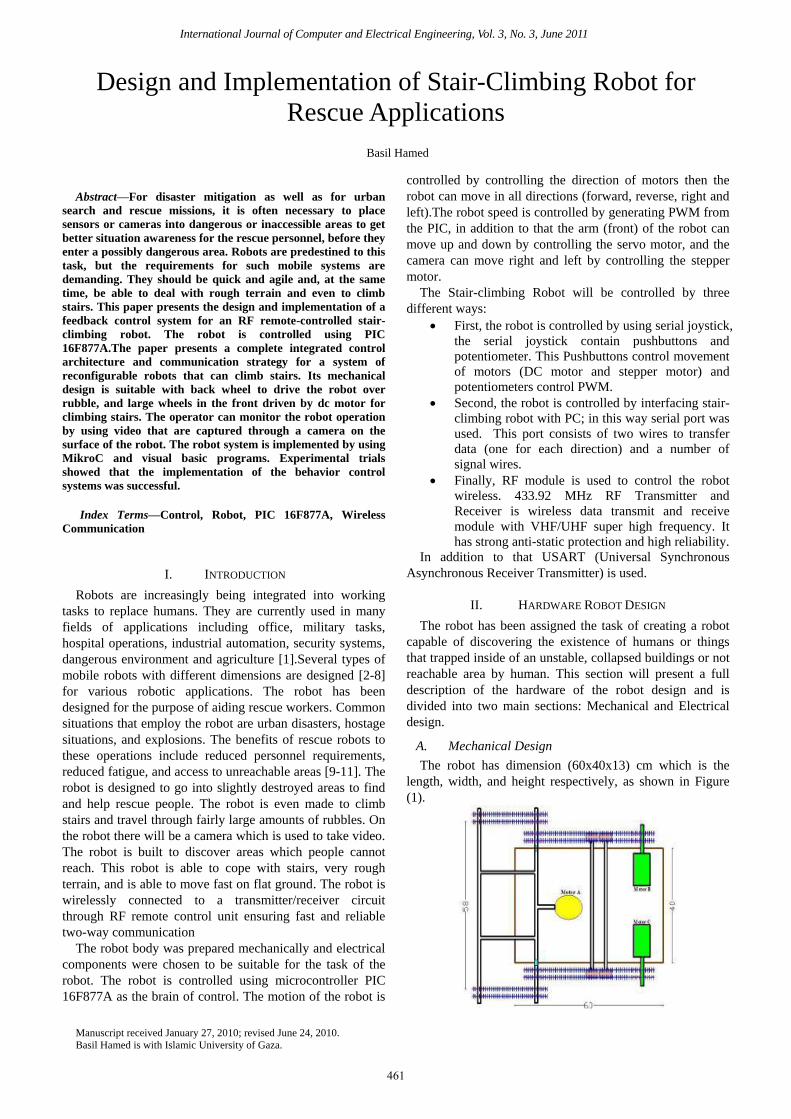
A. Mechanical Design
The robot has dimension (60x40x13) cm which is the
length, width, and height respectively, as shown in Figure
(1).
Design and Implementation of Stair-Climbing Robot for
Rescue Applications
Basil Hamed
461
Page 2
International Journal of Computer and Electrical Engineering, Vol. 3, No. 3, June 2011
Figure (1) Top View of the Robot
Gears and its Dimension
The robot requires twelve large gears with diameter of 17
cm, as shown in Figure (2) eight of them joined together for
robot movement to enable the robot to travel through fairly
large amounts of rubble,. The other four large gears join
with four small gears with a diameter of 8 cm to be able to
climb the stairs. We use a double bicycle chain to join the
gears.
Figure (2) Gears of the Robot
Robot Movement Mechanism:
The robot mechanism drive works with the rear wheels
being directly powered and the front wheel system being
driven by the same motor via a series chain. The movement
of the robot is established by using two motors in each side.
A servomotor with arm (Satellite Dish Motor) is used to the
case of climbing stairs by controlling the position of the
motor arm which is joined with the front of the robot
Advantages of Rear Wheel:
Maintenance is cheap and easy.
Fixed in long lines and roads.
It's Strong and less carrying havoc.
More comfortable and stable.
Non-pressure build-up on the front wheels.
Rear wheel has the task of spin, receiving torque
and acceleration, which leads to better control of
the robot.
The front wheel is responsible for the direction
and the rear back wheel is for push
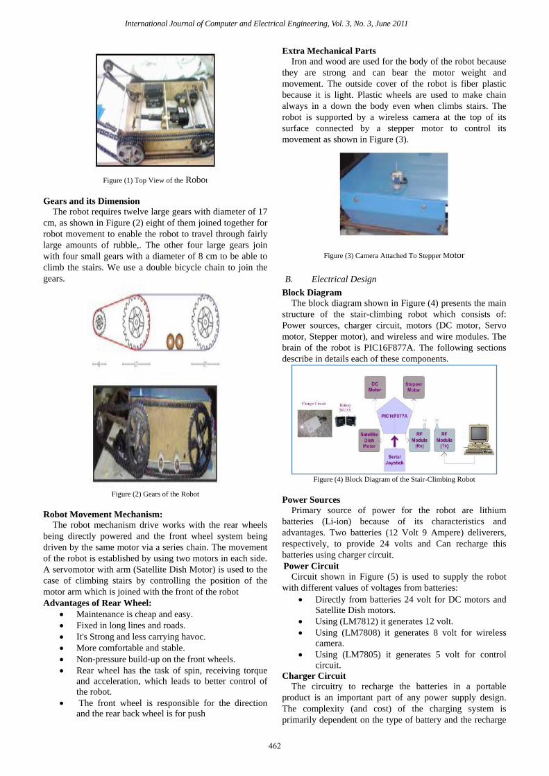
Extra Mechanical Parts
Iron and wood are used for the body of the robot because
they are strong and can bear the motor weight and
movement. The outside cover of the robot is fiber plastic
because it is light. Plastic wheels are used to make chain
always in a down the body even when climbs stairs. The
robot is supported by a wireless camera at the top of its
surface connected by a stepper motor to control its
movement as shown in Figure (3).
Figure (3) Camera Attached To Stepper Motor
B. Electrical Design
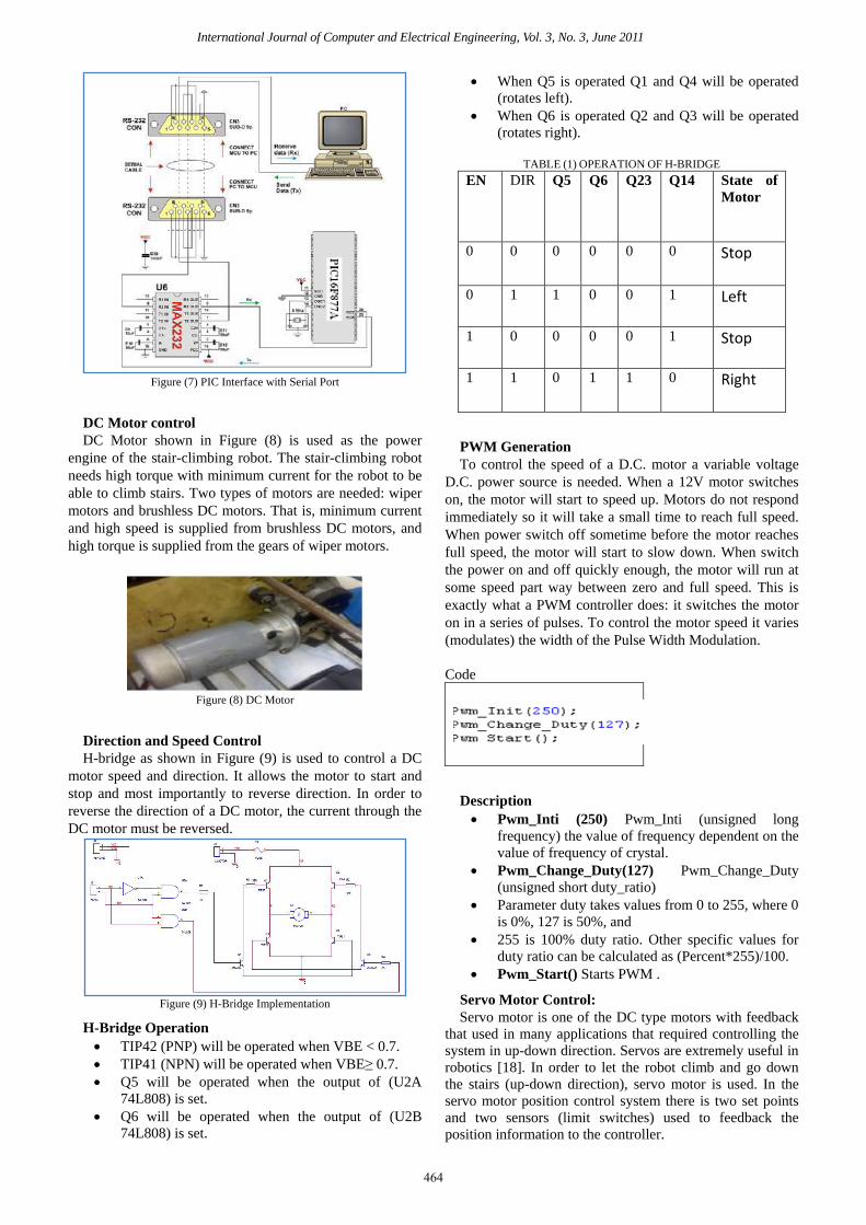
Block Diagram
The block diagram shown in Figure (4) presents the main
structure of the stair-climbing robot which consists of:
Power sources, charger circuit, motors (DC motor, Servo
motor, Stepper motor), and wireless and wire modules. The
brain of the robot is PIC16F877A. The following sections
describe in details each of these components.
Figure (4) Block Diagram of the Stair-Climbing Robot
Power Sources
Primary source of power for the robot are lithium
batteries (Li-ion) because of its characteristics and
advantages. Two batteries (12 Volt 9 Ampere) deliverers,
respectively, to provide 24 volts and Can recharge this
batteries using charger circuit.
Power Circuit
Circuit shown in Figure (5) is used to supply the robot
with different values of voltages from batteries:
Directly from batteries 24 volt for DC motors and
Satellite Dish motors.
Using (LM7812) it generates 12 volt.
Using (LM7808) it generates 8 volt for wireless
camera.
Using (LM7805) it generates 5 volt for control
circuit.
Charger Circuit
The circuitry to recharge the batteries in a portable
product is an important part of any power supply design.
The complexity (and cost) of the charging system is
primarily dependent on the type of battery and the recharge
462
Page 3
International Journal of Computer and Electrical Engineering, Vol. 3, No. 3, June 2011
time.
Figure (5) Power Circuit
As shown in Figure (6-b)when TR1 is set correctly then
the next round of charging it will be notice D1 begin to
flicker as the battery is being charged. When battery is
completely charged, D1 turns ON completely.TR1 do not
need further adjustment anymore. Q1 is connected in line
with the battery and is fired by R2, R3and D1. The R4, C1,
TR1 and D3 sense the voltage of the battery terminal and
activate Q2 when the voltage of the battery terminal exceeds
the value predetermined by TR1. When an uncharged
battery is connected, the terminal voltage is low. Under this
circumstance, Q2 is turned OFF and Q1 is fired in each half
cycle by R2, R3 andD1. The Q1 functions as a simple
rectifier and charges the battery. When the battery terminal
voltage is increased the level that had been fixed by TR1will
makes Q2shifts the control of Q1 gate. This deactivates Q1
and cuts off the current supply to the battery and turns D1
ON indicating that the charge has been completed. M1 is a
3ADC ammeter to measure the charge current. The AC/DC
controlled rectifier provides a variable DC load voltage
from a fixed voltage and frequency source (220 V ac, 50 Hz)
as shown in Figure (6-a).
Figure (6-a) Full wave Rectifier (AC/DC Converter)
Figure (6-b) Charger Circuit
III.
SOFTWARE
ROBOT DESIGN
The robot software complements the hardware
architecture of the stair-climbing robot by providing basic
low-level hardware control that include reading the sensors
value and controlling the motor speed.
Mikro C Program: Mikro C is a powerful, feature rich
development tool for PIC microcontroller. It is designed to
provide the programmer with the easiest possible solution
for developing applications for embedded systems, without
compromising performance or control. [12][13].
Proteus Program: Provides detailed instructions on how
to create new simulator models, using both schematic and
programmatic (DLL) based techniques. It is an interactive
system level simulator (Figure 19). Which combines mixed
mode circuit simulation, micro-processor models and
interactive component models to allow the simulation of
complete micro-controller based designs. [14]
OrCAD PCB Program: used for PCB design. An
interactive environment for creating and editing simple to
complex multi-layer PCBs, it uses powerful shape-based
algorithms for speed and efficient use of the routing area.
OrCAD facilitates rapid design-and-simulate cycles,
allowing engineers to explore various design configurations
before committing to a specific circuit implementation [15].
Visual Basic Program: used for Interfacing between PC
and the stair-climbing Robot. Microsoft Visual Basic 6.0 is
used in this paper because of its easy programming, easy
displaying of visual elements, availability. it is one of the
most popular programming languages and it is easy to
implement functions using it [16].
PIC16f877A
PIC16f877A is used as the brain of the robot that can be
programmed by connecting the serial port of the computer
to the PIC microcontroller. The serial port operates at +/-
13V, and the PIC serial operates at +5V/0V [17]. MAX232
is used as a level shifter to connect the serial port of the
computer to pins RX/TX on PIC as shown in Figure (7).
463
Page 4
International Journal of Computer and Electrical Engineering, Vol. 3, No. 3, June 2011
Figure (7) PIC Interface with Serial Port
DC Motor control
DC Motor shown in Figure (8) is used as the power
engine of the stair-climbing robot. The stair-climbing robot
needs high torque with minimum current for the robot to be
able to climb stairs. Two types of motors are needed: wiper
motors and brushless DC motors. That is, minimum current
and high speed is supplied from brushless DC motors, and
high torque is supplied from the gears of wiper motors.
Figure (8) DC Motor
Direction and Speed Control
H-bridge as shown in Figure (9) is used to control a DC
motor speed and direction. It allows the motor to start and
stop and most importantly to reverse direction. In order to
reverse the direction of a DC motor, the current through the
DC motor must be reversed.
Figure (9) H-Bridge Implementation
H-Bridge Operation
TIP42 (PNP) will be operated when VBE < 0.7.
TIP41 (NPN) will be operated when VBE≥ 0.7.
Q5 will be operated when the output of (U2A
74L808) is set.
Q6 will be operated when the output of (U2B
74L808) is set.
When Q5 is operated Q1 and Q4 will be operated
(rotates left).
When Q6 is operated Q2 and Q3 will be operated
(rotates right).
TABLE (1) OPERATION OF H-BRIDGE
EN DIR Q5 Q6 Q23 Q14 State of
Motor
0 0 0 0 0 0 Stop
0 1 1 0 0 1 Left
1 0 0 0 0 1 Stop
1 1 0 1 1 0 Right
PWM Generation
To control the speed of a D.C. motor a variable voltage
D.C. power source is needed. When a 12V motor switches
on, the motor will start to speed up. Motors do not respond
immediately so it will take a small time to reach full speed.
When power switch off sometime before the motor reaches
full speed, the motor will start to slow down. When switch
the power on and off quickly enough, the motor will run at
some speed part way between zero and full speed. This is
exactly what a PWM controller does: it switches the motor
on in a series of pulses. To control the motor speed it varies
(modulates) the width of the Pulse Width Modulation.
Code
Description
Pwm_Inti (250) Pwm_Inti (unsigned long
frequency) the value of frequency dependent on the
value of frequency of crystal.
Pwm_Change_Duty(127) Pwm_Change_Duty
(unsigned short duty_ratio)
Parameter duty takes values from 0 to 255, where 0
is 0%, 127 is 50%, and
255 is 100% duty ratio. Other specific values for
duty ratio can be calculated as (Percent*255)/100.
Pwm_Start() Starts PWM .
Servo Motor Control:
Servo motor is one of the DC type motors with feedback
that used in many applications that required controlling the
system in up-down direction. Servos are extremely useful in
robotics [18]. In order to let the robot climb and go down
the stairs (up-down direction), servo motor is used. In the
servo motor position control system there is two set points
and two sensors (limit switches) used to feedback the
position information to the controller.
464
Page 5
International Journal of Computer and Electrical Engineering, Vol. 3, No. 3, June 2011
L298N Dual Full-Bridge Motor Driver
L298 is a dual H-bridge driver as shown in Figure (10)
for DC brushed motors and stepper motors. It supports a
wide operating voltage range and can deliver 2 A per
channel in a through-hole package that is accessible for do-
it-yourself projects.
L298N Features and Specifications
Operation to 46 V
Up to 2 A per channel
Outputs can be paralleled to drive up to 3 A
Independent ground connections for each channel
allow independent current sensing.
Multiwatt15 through-hole package allows
convenient heat sink mounting and easy
prototyping with 0.1" breadboards.
L298N can control 2 DC Motors, their direction
using control lines and0 there. Speed using PWM.
Dish Satellite motor has a constant speed that is
why it has only direction control.
The outputs of the two motors are connected in
parallel to drive only one .motor to maximize the
output current of the bridge (3A).
Figure (10) L298 Dual Full-Bridge Driver
Stepper Motor Control
A stepper Motor is an electromechanical device which
converts electrical pulses into discrete mechanical
movement. The shaft or spindle of a stepper motor rotates
indiscrete step increment when electrical command pulses
are applied to it in the proper sequence. The sequence of the
applied pulses is directly related to the direction of the
motor shaft rotation [19]. The main advantage of stepper
motors is that they can achieve accurate position control
without the requirement for position feedback. Stepper
motor is used for the rotation of the camera in both Left and
Right directions.
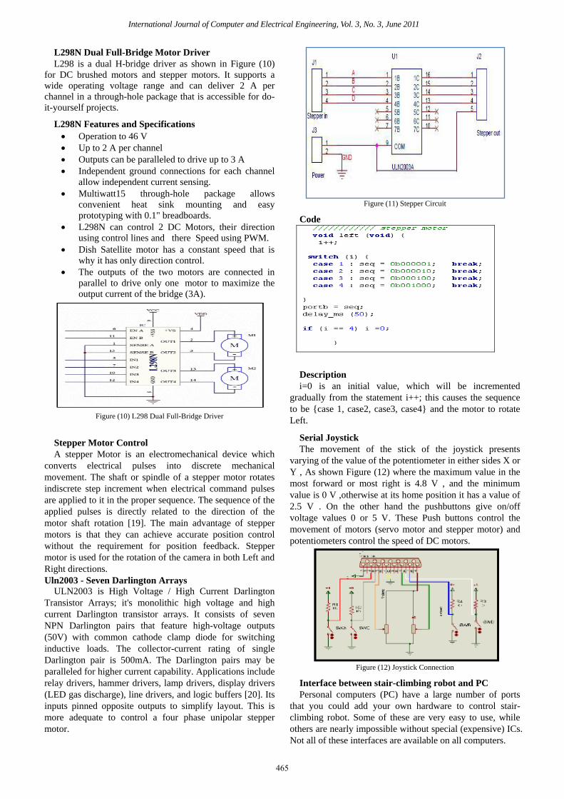
Uln2003 - Seven Darlington Arrays
ULN2003 is High Voltage / High Current Darlington
Transistor Arrays; it's monolithic high voltage and high
current Darlington transistor arrays. It consists of seven
NPN Darlington pairs that feature high-voltage outputs
(50V) with common cathode clamp diode for switching
inductive loads. The collector-current rating of single
Darlington pair is 500mA. The Darlington pairs may be
paralleled for higher current capability. Applications include
relay drivers, hammer drivers, lamp drivers, display drivers
(LED gas discharge), line drivers, and logic buffers [20]. Its
inputs pinned opposite outputs to simplify layout. This is
more adequate to control a four phase unipolar stepper
motor.
Figure (11) Stepper Circuit
Code
Description
i=0 is an initial value, which will be incremented
gradually from the statement i++; this causes the sequence
to be {case 1, case2, case3, case4} and the motor to rotate
Left.
Serial Joystick
The movement of the stick of the joystick presents
varying of the value of the potentiometer in either sides X or
Y , As shown Figure (12) where the maximum value in the
most forward or most right is 4.8 V , and the minimum
value is 0 V ,otherwise at its home position it has a value of
2.5 V . On the other hand the pushbuttons give on/off
voltage values 0 or 5 V. These Push buttons control the
movement of motors (servo motor and stepper motor) and
potentiometers control the speed of DC motors.
Figure (12) Joystick Connection
Interface between stair-climbing robot and PC
Personal computers (PC) have a large number of ports
that you could add your own hardware to control stair-
climbing robot. Some of these are very easy to use, while
others are nearly impossible without special (expensive) ICs.
Not all of these interfaces are available on all computers.
465
Page 6
International Journal of Computer and Electrical Engineering, Vol. 3, No. 3, June 2011
Serial Port
The serial port as shown in Figure (13) is one of the two
easiest to use ports on a PC. This port consists of 2 wires to
transfer data (one for each direction) and a number of signal
wires. This port is reasonably sturdy, and knowing digital
electronics and how to use a microcontroller, is pretty easy
to use. It is limited on speed and can only connect two
devices directly.
Figure (13) RS-232 Serial Communication
USART
USART stands for Universal Synchronous Asynchronous
Receiver Transmitter. It is sometimes called the Serial
Communications Interface or SCI. Synchronous operation
uses a clock and data line while there is no separate clock
accompanying the data for Asynchronous transmission.
Since there is no clock signal in asynchronous operation,
one pin can be used for transmission and another pin can be
used for reception. Both transmission and reception can
occur at the same time - this is known as full duplex
operation. Transmission and reception can be independently
enabled. However, when the serial port is enabled, the
USART will control both pins and one cannot be used for
general-purpose I/O when the other is being used for
transmission or reception. The most common use of the
USART in asynchronous mode is to communicate to a PC
serial port using the RS-232 protocol. A driver is required to
interface to RS-232 voltage levels and the PIC; MCU
should not be directly connected to RS-232 signals [21].
MAX232 is used as a driver (voltage level shifter) as
explained earlier.
USART Library:
USART hardware module is available with
PIC16F877A .This library is used to communicate between
PC and PIC16F877A, thus we enabled to control the robot
via mouse or USB joystick
Code
Description
USART_InitInitializeshardware USART module
with the desired baud rate.
UsartData_Ready () USART_ReadIf data is
ready, read it.
Then the received data will be examined and the proper
function will be executed.
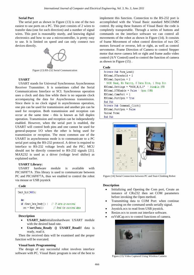
Visual basic Programming
The design of any successful robot involves interface
software with PC. Visual Basic program is one of the best to
implement this function. Connection to the RS-232 port is
accomplished with the Visual Basic standard MSCOMM
control. By using these features of Visual Basic the code is
completely transportable. Through a series of buttons and
commands on the interface software we can control all
movements of the robot as shown in Figure (14). It consists
of frame Movement of robot control direction of two DC
motors forward or reverse, left or right, as well as control
servomotor. Frame Direction of Camera to control Stepper
motor that move camera left or right and frame audio video
control (A/V Control) used to control the function of camera
as shown in Figure (15) .
Code
Figure (14) Serial Connection between PC and Stair-Climbing Robot
Description
Initializing and Opening the Com port, Create an
instance of CRs232 then set0COM parameters
before invoking the Open method.
Transmitting data to COM Port: when continue
pressing on the command sends serially signal.
Joystick.ocx to read from USB joystick.
Resize.ocx to zoom out interface software.
ezVidCap.ocx to control functions of camera.
Figure (15) Video Captured Using Wireless Camera
466
Page 7
International Journal of Computer and Electrical Engineering, Vol. 3, No. 3, June 2011
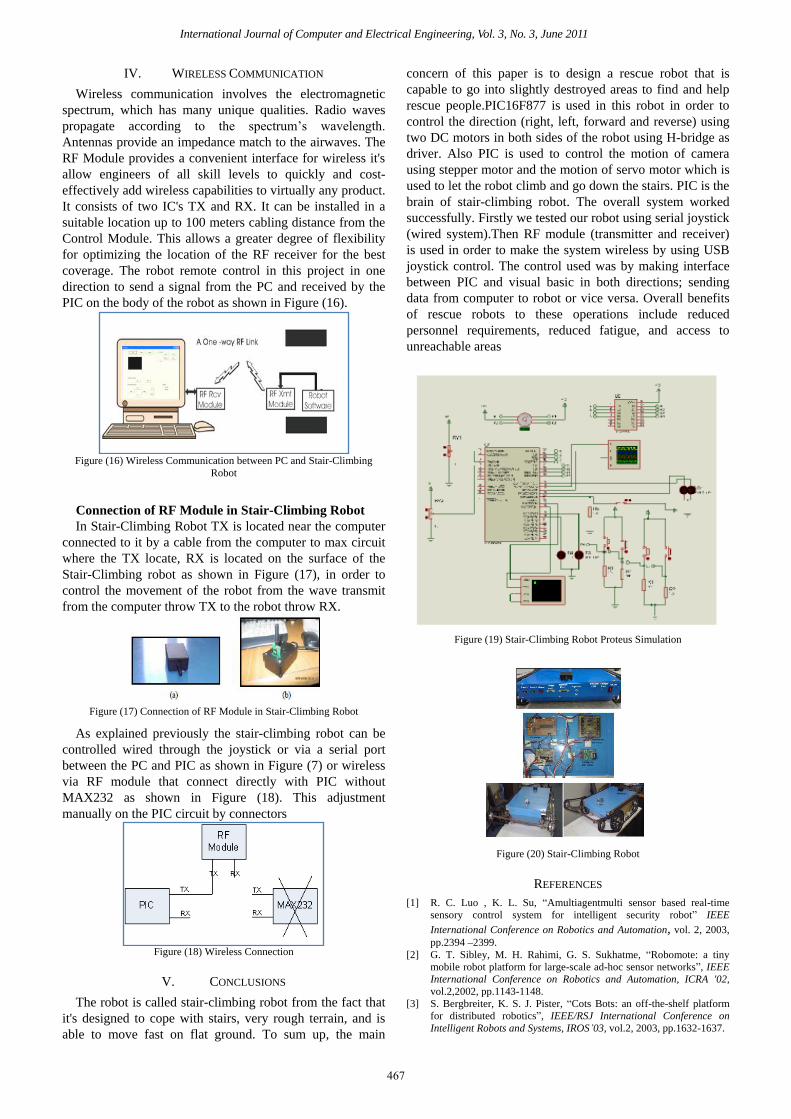
IV. WIRELESS COMMUNICATION
Wireless communication involves the electromagnetic
spectrum, which has many unique qualities. Radio waves
propagate according to the spectrum’s wavelength.
Antennas provide an impedance match to the airwaves. The
RF Module provides a convenient interface for wireless it's
allow engineers of all skill levels to quickly and cost-
effectively add wireless capabilities to virtually any product.
It consists of two IC's TX and RX. It can be installed in a
suitable location up to 100 meters cabling distance from the
Control Module. This allows a greater degree of flexibility
for optimizing the location of the RF receiver for the best
coverage. The robot remote control in this project in one
direction to send a signal from the PC and received by the
PIC on the body of the robot as shown in Figure (16).
Figure (16) Wireless Communication between PC and Stair-Climbing
Robot
Connection of RF Module in Stair-Climbing Robot
In Stair-Climbing Robot TX is located near the computer
connected to it by a cable from the computer to max circuit
where the TX locate, RX is located on the surface of the
Stair-Climbing robot as shown in Figure (17), in order to
control the movement of the robot from the wave transmit
from the computer throw TX to the robot throw RX.
Figure (17) Connection of RF Module in Stair-Climbing Robot
As explained previously the stair-climbing robot can be
controlled wired through the joystick or via a serial port
between the PC and PIC as shown in Figure (7) or wireless
via RF module that connect directly with PIC without
MAX232 as shown in Figure (18). This adjustment
manually on the PIC circuit by connectors
Figure (18) Wireless Connection
V. CONCLUSIONS
The robot is called stair-climbing robot from the fact that
it's designed to cope with stairs, very rough terrain, and is
able to move fast on flat ground. To sum up, the main
concern of this paper is to design a rescue robot that is
capable to go into slightly destroyed areas to find and help
rescue people.PIC16F877 is used in this robot in order to
control the direction (right, left, forward and reverse) using
two DC motors in both sides of the robot using H-bridge as
driver. Also PIC is used to control the motion of camera
using stepper motor and the motion of servo motor which is
used to let the robot climb and go down the stairs. PIC is the
brain of stair-climbing robot. The overall system worked
successfully. Firstly we tested our robot using serial joystick
(wired system).Then RF module (transmitter and receiver)
is used in order to make the system wireless by using USB
joystick control. The control used was by making interface
between PIC and visual basic in both directions; sending
data from computer to robot or vice versa. Overall benefits
of rescue robots to these operations include reduced
personnel requirements, reduced fatigue, and access to
unreachable areas
Figure (19) Stair-Climbing Robot Proteus Simulation
Figure (20) Stair-Climbing Robot
REFERENCES
[1] R. C. Luo , K. L. Su, “Amultiagentmulti sensor based real-time
sensory control system for intelligent security robot” IEEE
International Conference on Robotics and Automation, vol. 2, 2003,
pp.2394 –2399.
[2] G. T. Sibley, M. H. Rahimi, G. S. Sukhatme, “Robomote: a tiny
mobile robot platform for large-scale ad-hoc sensor networks”, IEEE
International Conference on Robotics and Automation, ICRA '02,
vol.2,2002, pp.1143-1148.
[3] S. Bergbreiter, K. S. J. Pister, “Cots Bots: an off-the-shelf platform
for distributed robotics”, IEEE/RSJ International Conference on
Intelligent Robots and Systems, IROS’03, vol.2, 2003, pp.1632-1637.
467
Page 8
International Journal of Computer and Electrical Engineering, Vol. 3, No. 3, June 2011
[4] A. Arora, E. Ertin, R. Ramnath, M. Nesterenko, W. Leal, “Kansei:
high-fidelity sensing tested”, IEEE Internet Computing, vol.10,
2006,pp. 35- 47.
[5] H. Utz, S. Sablatnog, S. Enderle, G. Kraetzschmar, “Miro–
middlewarefor mobile robot applications”, IEEE Transactions on
Robotics and Automation, vol.18, 2002, pp. 493- 497.
[6] G. Caprari, K. O. Arras, R. Siegwart, “The autonomous miniature
robot Alice: from prototypes to applications”, IEEE/RSJ International
Conference on Intelligent Robots and Systems, IROS 2000, vol.1,
2000, pp. 793-798.
[7] G. Metta, P. Fitzpatrick, L. Natale,YARP: “Yet another Robot
Platform”, International Journal of Advanced Robotic Systems, vol. 3,
2006, pp.43-48.
[8] Kalantari, A. Mihankhah, E. Moosavian, S.A.A. “Safe autonomous
stair climbing for a tracked mobile robot using a kinematics based
controller” AIM. IEEE/ASME International Conference on Advanced
Intelligent Mechatronics, 2009.
[9] Akhtaruzzaman, M.; IzzatiBt Samsuddin, N.; Bt Umar, N.; Rahman,
M.;” Design and development of a wall climbing Robot and its
control system” 12th International Conference on Computers and
Information Technology, 2009. ICCIT '09.
[10] Sung Kyun Lim Dong Il Park Yoon Keun Kwak Byung-Soo Kim
Sang-Won Jeon, “ Variable geometry single-tracked mechanism for a
rescue robot” , Workshop, 2005 IEEE International Safety, Security
and Rescue Robotics.
[11] Gaston, J. Raahemifar, K. Hiscocks, P “ A cooperative network of
reconfigurable stair-climbing robots”, ISCAS 2006. Proceedings.
IEEE International Symposium on Circuits and Systems, 2006.
[12] PIC Microcontrollers 1st EDITION (2008) Milan Verle,
mikroElektronika
[13] Muhammad Ali Mazidi, Rolin D. Mackinaly, Danny Causey, “PIC
MICROCONTROLLER AND EMBEDDED SYSTEMS Using
Assembly and C for PIC18,” New Jersey, Prentice Hall, 2006.
[14] Proteus Professional PCB Design and Simulation
www.labcenter.co.uk/
[15] http://www.cadence.com/products/orcad/orcad_pcb_designer/pages/d
efault.aspx
[16] Osama El Huseni, “Visual Basic for Windows,” IbnSina Library,
1994.
[17] PIC16F87XA Datasheet, Pin Enhanced Flash Microcontrollers,
Microchip Technology Inc., 2003.
[18] Riazollah Firoozian,” Servo Motors and Industrial Control Theory”
Springer; 1st edition (December 8, 2008)
[19] Kenjo, Takashi,“Stepping motors and their microprocessor controls”
Oxford University Press, c1984.
[20] http://www.datasheetdir.com/ULN2003+Darlin gton-Transistor-
Arrays
[21] http://www.alldatasheet.com/datasheetpdf/pdf25575/STMICROELE
CTRONICS/ULN2003.html
Dr. Basil Hamed is Assistant Professor of Electrical Engineering
Department, Islamic University of Gaza, Palestine, since 1999. He has
Bachelor Degree in Electrical Engineering from New Mexico State
University, NM. USA in the year of 1989, he received Master degree from
University of New Orleans, La. USA in the year of 1992, and earned his
PhD from New Mexico State University, NM USA in the year 1999. He
has 15 years of teaching experience and has published many papers in
national and international journals. His fields of interest include Control
Systems, Fuzzy Control, Simulation & Modeling, Robotics, FPGA, Signal
and Image Processing.
468