162
Videojet 1220/1520 Operator Manual P/N 462268-01 Revision AA, July 2011
Videojet 1220/1520
Operator Manual
P/N 462268-01
Revision AA, July 2011
Copyright July 2011, Videojet Technologies Inc. (herein referred to as Videojet). All rights reserved.
This document is the property of Videojet Technologies Inc. and contains confidential and proprietary information owned by Videojet. Any unauthorized copying, use or disclosure of it without
the prior written permission of Videojet is strictly prohibited.
Videojet Technologies Inc.1500 Mittel Boulevard Phone: 1-800-843-3610 Offices - USA: Atlanta, Chicago, Los Angeles, PhiladelphiaWood Dale, IL Fax: 1-800-582-1343 INT’L: Canada, France, Germany, Ireland, Japan, Spain, 60191-1073 USA Int’l Fax: 630-616-3629 Singapore, The Netherlands,The United Kingdom www.videojet.com Distributors Worldwide
Rev AA i
Compliance Information
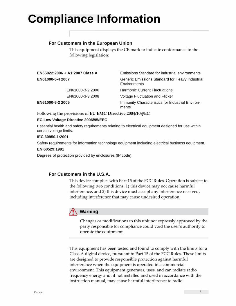
For Customers in the European UnionThis equipment displays the CE mark to indicate conformance to the following legislation:
For Customers in the U.S.A.This device complies with Part 15 of the FCC Rules. Operation is subject to the following two conditions: 1) this device may not cause harmful interference, and 2) this device must accept any interference received, including interference that may cause undesired operation.
Warning
Changes or modifications to this unit not expressly approved by the party responsible for compliance could void the user’s authority to operate the equipment.
This equipment has been tested and found to comply with the limits for a Class A digital device, pursuant to Part 15 of the FCC Rules. These limits are designed to provide responsible protection against harmful interference when the equipment is operated in a commercial environment. This equipment generates, uses, and can radiate radio frequency energy and, if not installed and used in accordance with the instruction manual, may cause harmful interference to radio
EN55022:2006 + A1:2007 Class A Emissions Standard for industrial environmentsEN61000-6-4 2007 Generic Emissions Standard for Heavy Industrial
EnvironmentsEN61000-3-2 2006 Harmonic Current Fluctuations EN61000-3-3 2008 Voltage Fluctuation and Flicker
EN61000-6-2 2005 Immunity Characteristics for Industrial Environ-ments
Following the provisions of EU EMC Directive 2004/108/ECEC Low Voltage Directive 2006/95/EECEssential health and safety requirements relating to electrical equipment designed for use within certain voltage limits.IEC 60950-1:2001Safety requirements for information technology equipment including electrical business equipment.EN 60529:1991Degrees of protection provided by enclosures (IP code).

Videojet 1220/1520 Operator Manual
ii Rev AA
communications. Operation of this equipment in a residential area is likely to cause harmful interference in which case the user will be required to correct the interference at his own expense.
Shielded cables must be used with this unit to ensure compliance with Class A FCC limits.
The user may find the following booklet prepared by the Federal Communications Commission helpful: How to Identify and Resolve Radio-TV Interference Problems. This booklet is available from the U.S. Government Printing Office, Washington, DC 20402, Stock No. 004-00-00345-4.
This equipment has been tested and certified for compliance with U.S. regulations regarding safety and electrical emissions by:
Electromagnetic Testing Services Limited
Pratts Fields
Lubberhedges Lane
Stebbing, Dunmow
Essex, CM6 3BT
England, UK
This equipment has been investigated by Underwriters Laboratories Inc. in accordance with the standard for safety: UL 60950-1: Safety of information technology equipment first edition. Subject 2178 marking and coding equipment, electronics.
Report reference E252185.
For Customers in CanadaThis digital apparatus does not exceed the Class A limits for radio noise emissions from digital apparatus set out in the Radio Interference Regulations of the Canadian Department of Communications.
This equipment has been tested and certified for compliance with Canadian regulations regarding safety and electrical emissions by:
Electromagnetic Testing Services Limited
Pratts Fields
Lubberhedges Lane
Stebbing, Dunmow
Essex, CM6 3BT
England, UK
Videojet 1220/1520 Operator Manual
Rev AA iii
This equipment has been investigated by Underwriters Laboratories Incorporated in accordance with the standard for safety: CAN/CSA C22.2 No. 60950-1-03. Safety of information technology equipment. Subject 2178 marking and coding equipment, electronics.
Report reference E252185.
Pour la clientèle du CanadaLe present appareil numerique n’emet pas de bruits radioelectriques depassant les limites applicales aux appareils numerique de las class A prescrites dans le Reglement sur le brouillage radioelectrique edicte par le ministere des Communications du Canada.
Cet équipement est certifié CSA.
This equipment has been investigated by Underwriters Laboratories Incorporated in accordance with the standard for safety: CAN/CSA C22.2 No. 60950-1-03. Safety of information technology equipment. Subject 2178 marking and coding equipment, electronics.
Report reference E252185.
Warning
This product is not intended for use in the immediate/direct visual field of the display work place. To avoid disturbing reflections on the display work place, this product shall not be placed in the immediate/direct field of vision.
Rev AA iv
Customer Support and Training
Contact InformationIf you have any questions or need assistance, please contact Videojet Technologies Inc. at 1-800-843-3610 (for all customers within the United States). Outside the U.S., customers should contact their Videojet Technologies Inc. distributor or subsidiary for assistance.
Videojet Technologies Inc.
1500 Mittel Boulevard
Wood Dale, IL 60191-1073 U.S.A.
Phone: 1-800-843-3610
Fax: 1-800-582-1343
International Fax: 630-616-3629
Web: www.videojet.com
Service ProgramAbout Total Source CommitmentTotal Source® TOTAL SERVICE PLUS RELIABILITY, is the Videojet Technologies Inc. commitment to provide you - our customer - the complete service you deserve.
The Total Source CommitmentThe Videojet Total Source® Service Program is an integral part of our business in providing marks, codes, and images where, when, and how often customers specify for packages, products, or printed materials. Our commitment includes:
• Applications support.
• Installation services.
• Maintenance training.
• Customer response center.
• Technical support.
• Field service.
• Extended hours phone assistance.
• Parts and supplies.
• Repair service.
Videojet 1220/1520 Operator Manual
Rev AA v
Customer TrainingIf you wish to perform your own service and maintenance on the printer, Videojet Technologies Inc. highly recommends you complete a Customer Training Course on the printer.
Note: The manuals are intended to be supplements to (and not replacements for) Videojet Technologies Inc. Customer Training.
For more information on Videojet Technologies Inc. Customer Training Courses, call 1-800-843-3610 (within the United States only). Outside the U.S., customer should contact a Videojet subsidiary office or the local Videojet distributor for further information.
Rev AA 1
Table of ContentsCompliance Information
For Customers in the European Union. . . . . . . . . . . . . . . . . . . . . . . . . . . . iFor Customers in the U.S.A.. . . . . . . . . . . . . . . . . . . . . . . . . . . . . . . . . . . . iFor Customers in Canada . . . . . . . . . . . . . . . . . . . . . . . . . . . . . . . . . . . . . . iiPour la clientèle du Canada. . . . . . . . . . . . . . . . . . . . . . . . . . . . . . . . . . . . iii
Customer Support and TrainingContact Information . . . . . . . . . . . . . . . . . . . . . . . . . . . . . . . . . . . . . . . . . ivService Program . . . . . . . . . . . . . . . . . . . . . . . . . . . . . . . . . . . . . . . . . . . . ivCustomer Training . . . . . . . . . . . . . . . . . . . . . . . . . . . . . . . . . . . . . . . . . . . v
Chapter 1 — IntroductionVideojet 1220/1520 Printer . . . . . . . . . . . . . . . . . . . . . . . . . . . . . . . . . . . 1–1About the Manual. . . . . . . . . . . . . . . . . . . . . . . . . . . . . . . . . . . . . . . . . . . 1–1Related Publications. . . . . . . . . . . . . . . . . . . . . . . . . . . . . . . . . . . . . . . . . 1–1
Language Codes. . . . . . . . . . . . . . . . . . . . . . . . . . . . . . . . . . . . . . . . . 1–1Content Presentation . . . . . . . . . . . . . . . . . . . . . . . . . . . . . . . . . . . . . . . . 1–3
Positional References. . . . . . . . . . . . . . . . . . . . . . . . . . . . . . . . . . . . . 1–3Units of Measurement. . . . . . . . . . . . . . . . . . . . . . . . . . . . . . . . . . . . 1–3Safety Information . . . . . . . . . . . . . . . . . . . . . . . . . . . . . . . . . . . . . . . 1–3
Warning. . . . . . . . . . . . . . . . . . . . . . . . . . . . . . . . . . . . . . . . . . . . . . 1–3Caution . . . . . . . . . . . . . . . . . . . . . . . . . . . . . . . . . . . . . . . . . . . . . . 1–3
Notes . . . . . . . . . . . . . . . . . . . . . . . . . . . . . . . . . . . . . . . . . . . . . . . . . . 1–4User Interface Terminology . . . . . . . . . . . . . . . . . . . . . . . . . . . . . . . 1–4
Abbreviations and Acronyms. . . . . . . . . . . . . . . . . . . . . . . . . . . . . . . . . 1–6Chapters in the Manual . . . . . . . . . . . . . . . . . . . . . . . . . . . . . . . . . . . . . . 1–6
Chapter 2 — SafetyIntroduction. . . . . . . . . . . . . . . . . . . . . . . . . . . . . . . . . . . . . . . . . . . . . . . . 2–1General Safety Guidelines. . . . . . . . . . . . . . . . . . . . . . . . . . . . . . . . . . . . 2–1Electrical Safety Guidelines. . . . . . . . . . . . . . . . . . . . . . . . . . . . . . . . . . . 2–2
Electrical Power Supply . . . . . . . . . . . . . . . . . . . . . . . . . . . . . . . . . . 2–2Electrical Cables . . . . . . . . . . . . . . . . . . . . . . . . . . . . . . . . . . . . . . . . . 2–3Grounding and Bonding. . . . . . . . . . . . . . . . . . . . . . . . . . . . . . . . . . 2–3Fuses . . . . . . . . . . . . . . . . . . . . . . . . . . . . . . . . . . . . . . . . . . . . . . . . . . 2–5
Fluid Safety Guidelines . . . . . . . . . . . . . . . . . . . . . . . . . . . . . . . . . . . . . . 2–5Read the Material Safety Data Sheets . . . . . . . . . . . . . . . . . . . . . . . 2–5Ink and Make-up Fluid . . . . . . . . . . . . . . . . . . . . . . . . . . . . . . . . . . . 2–6Cleaning Solution. . . . . . . . . . . . . . . . . . . . . . . . . . . . . . . . . . . . . . . . 2–7
Compressed Air Safety Guidelines . . . . . . . . . . . . . . . . . . . . . . . . . . . . 2–8UI Related Safety Guidelines . . . . . . . . . . . . . . . . . . . . . . . . . . . . . . . . . 2–8
Videojet 1220/1520 Operator Manual
2 Rev AA
Other Important Guidelines . . . . . . . . . . . . . . . . . . . . . . . . . . . . . . . . . . 2–9
Chapter 3 — Main PartsVideojet 1220/1520 Printer . . . . . . . . . . . . . . . . . . . . . . . . . . . . . . . . . . . 3–1Control Panel . . . . . . . . . . . . . . . . . . . . . . . . . . . . . . . . . . . . . . . . . . . . . . . 3–3
Status LEDs . . . . . . . . . . . . . . . . . . . . . . . . . . . . . . . . . . . . . . . . . . . . . 3–3Arrow Keys . . . . . . . . . . . . . . . . . . . . . . . . . . . . . . . . . . . . . . . . . . . . . 3–4Keypad . . . . . . . . . . . . . . . . . . . . . . . . . . . . . . . . . . . . . . . . . . . . . . . . . 3–4Display . . . . . . . . . . . . . . . . . . . . . . . . . . . . . . . . . . . . . . . . . . . . . . . . . 3–4Contrast Keys . . . . . . . . . . . . . . . . . . . . . . . . . . . . . . . . . . . . . . . . . . . 3–4Function Keys . . . . . . . . . . . . . . . . . . . . . . . . . . . . . . . . . . . . . . . . . . . 3–4Display Screen. . . . . . . . . . . . . . . . . . . . . . . . . . . . . . . . . . . . . . . . . . . 3–5
Electronics Compartment . . . . . . . . . . . . . . . . . . . . . . . . . . . . . . . . . . . . 3–6Ink Compartment . . . . . . . . . . . . . . . . . . . . . . . . . . . . . . . . . . . . . . . . . . . 3–8
Ink Core Module. . . . . . . . . . . . . . . . . . . . . . . . . . . . . . . . . . . . . . . . . 3–8Smart Cartridge . . . . . . . . . . . . . . . . . . . . . . . . . . . . . . . . . . . . . . . . . 3–9Ink Compartment Fan . . . . . . . . . . . . . . . . . . . . . . . . . . . . . . . . . . . . 3–9
Printhead and Umbilical . . . . . . . . . . . . . . . . . . . . . . . . . . . . . . . . . . . . . 3–9Connector Panel . . . . . . . . . . . . . . . . . . . . . . . . . . . . . . . . . . . . . . . . . . . 3–11
Pinout Information. . . . . . . . . . . . . . . . . . . . . . . . . . . . . . . . . . . . . . 3–12Main Power Switch. . . . . . . . . . . . . . . . . . . . . . . . . . . . . . . . . . . . . . . . . 3–13Back Filter. . . . . . . . . . . . . . . . . . . . . . . . . . . . . . . . . . . . . . . . . . . . . . . . . 3–13
Chapter 4 — Printer OperationIntroduction . . . . . . . . . . . . . . . . . . . . . . . . . . . . . . . . . . . . . . . . . . . . . . . . 4–1How to Turn on the Printer . . . . . . . . . . . . . . . . . . . . . . . . . . . . . . . . . . . 4–1How to Clean Start and Stop the Printer . . . . . . . . . . . . . . . . . . . . . . . . 4–2
How to Clean Start . . . . . . . . . . . . . . . . . . . . . . . . . . . . . . . . . . . . . . . 4–2How to Clean Stop . . . . . . . . . . . . . . . . . . . . . . . . . . . . . . . . . . . . . . . 4–2
How to Set the Passwords . . . . . . . . . . . . . . . . . . . . . . . . . . . . . . . . . . . . 4–2How to Login for the First Time. . . . . . . . . . . . . . . . . . . . . . . . . . . . 4–3How to Set the Passwords for Levels 1 and 2 . . . . . . . . . . . . . . . . 4–3How to Set the Password Levels for Menus. . . . . . . . . . . . . . . . . . 4–4How to Access Other Password Levels. . . . . . . . . . . . . . . . . . . . . . 4–6How to Clear the Password . . . . . . . . . . . . . . . . . . . . . . . . . . . . . . . 4–6Auto Logout . . . . . . . . . . . . . . . . . . . . . . . . . . . . . . . . . . . . . . . . . . . . 4–7
System Menu . . . . . . . . . . . . . . . . . . . . . . . . . . . . . . . . . . . . . . . . . . . . . . . 4–7Calibrate Menu . . . . . . . . . . . . . . . . . . . . . . . . . . . . . . . . . . . . . . . . . . . . . 4–8Data Logging Menu . . . . . . . . . . . . . . . . . . . . . . . . . . . . . . . . . . . . . . . . 4–10
How to View Version Information . . . . . . . . . . . . . . . . . . . . . . . . 4–10Product Counter . . . . . . . . . . . . . . . . . . . . . . . . . . . . . . . . . . . . . . . . . . . 4–11
How to Reset the Product Counter . . . . . . . . . . . . . . . . . . . . . . . . 4–11
Videojet 1220/1520 Operator Manual
Rev AA 3
How to Hide the Product Counter . . . . . . . . . . . . . . . . . . . . . . . . 4–11 Run Hours . . . . . . . . . . . . . . . . . . . . . . . . . . . . . . . . . . . . . . . . . . . . . . . 4–12
How to View Run Hours . . . . . . . . . . . . . . . . . . . . . . . . . . . . . . . . 4–12How to Reset Run Hours . . . . . . . . . . . . . . . . . . . . . . . . . . . . . . . . 4–12
How to Configure the Serial Port. . . . . . . . . . . . . . . . . . . . . . . . . . . . . 4–13How to Configure Ethernet Port . . . . . . . . . . . . . . . . . . . . . . . . . . . . . 4–14How to Enter Service Information . . . . . . . . . . . . . . . . . . . . . . . . . . . . 4–14How to Create a Message . . . . . . . . . . . . . . . . . . . . . . . . . . . . . . . . . . . 4–15Printer Configuration. . . . . . . . . . . . . . . . . . . . . . . . . . . . . . . . . . . . . . . 4–15
Print Enable. . . . . . . . . . . . . . . . . . . . . . . . . . . . . . . . . . . . . . . . . . . . 4–15Manual Print Option . . . . . . . . . . . . . . . . . . . . . . . . . . . . . . . . . . . . 4–17How to Use Continuous Print Option . . . . . . . . . . . . . . . . . . . . . 4–17DIN Print. . . . . . . . . . . . . . . . . . . . . . . . . . . . . . . . . . . . . . . . . . . . . . 4–18
How to Print Messages . . . . . . . . . . . . . . . . . . . . . . . . . . . . . . . . . . . . . 4–18How to Select a Message. . . . . . . . . . . . . . . . . . . . . . . . . . . . . . . . . 4–19How to Start the Printing . . . . . . . . . . . . . . . . . . . . . . . . . . . . . . . . 4–19
Monitor the Printing . . . . . . . . . . . . . . . . . . . . . . . . . . . . . . . . . . 4–20How to Stop the Printing . . . . . . . . . . . . . . . . . . . . . . . . . . . . . . . . 4–20
How to Install and Print Custom Fonts . . . . . . . . . . . . . . . . . . . . . . . 4–20Installation . . . . . . . . . . . . . . . . . . . . . . . . . . . . . . . . . . . . . . . . . . 4–21Create and Print a Message . . . . . . . . . . . . . . . . . . . . . . . . . . . . 4–21
Turn off the Printer. . . . . . . . . . . . . . . . . . . . . . . . . . . . . . . . . . . . . . . . . 4–22
Chapter 5 — User InterfaceIntroduction. . . . . . . . . . . . . . . . . . . . . . . . . . . . . . . . . . . . . . . . . . . . . . . . 5–1
To Select the Menus and Items . . . . . . . . . . . . . . . . . . . . . . . . . . . . 5–2To Enter the Text, Numbers and Toggle Values . . . . . . . . . . . . . . 5–3
Menu Description. . . . . . . . . . . . . . . . . . . . . . . . . . . . . . . . . . . . . . . . . . . 5–6Messages . . . . . . . . . . . . . . . . . . . . . . . . . . . . . . . . . . . . . . . . . . . . . . . 5–6Editor . . . . . . . . . . . . . . . . . . . . . . . . . . . . . . . . . . . . . . . . . . . . . . . . . . 5–8User Fields . . . . . . . . . . . . . . . . . . . . . . . . . . . . . . . . . . . . . . . . . . . . . 5–9Print . . . . . . . . . . . . . . . . . . . . . . . . . . . . . . . . . . . . . . . . . . . . . . . . . . 5–10Password . . . . . . . . . . . . . . . . . . . . . . . . . . . . . . . . . . . . . . . . . . . . . . 5–11System . . . . . . . . . . . . . . . . . . . . . . . . . . . . . . . . . . . . . . . . . . . . . . . . 5–12Configure . . . . . . . . . . . . . . . . . . . . . . . . . . . . . . . . . . . . . . . . . . . . . 5–13
Manage Messages. . . . . . . . . . . . . . . . . . . . . . . . . . . . . . . . . . . . . . . . . . 5–18To Create a Message . . . . . . . . . . . . . . . . . . . . . . . . . . . . . . . . . . . . 5–18To Edit a Message . . . . . . . . . . . . . . . . . . . . . . . . . . . . . . . . . . . . . . 5–20To Select the Source for a Message . . . . . . . . . . . . . . . . . . . . . . . . 5–21To Copy and Paste a Message . . . . . . . . . . . . . . . . . . . . . . . . . . . . 5–22To Enter Multiple Lines in a Message. . . . . . . . . . . . . . . . . . . . . . 5–22To Set the Message and Default Parameters . . . . . . . . . . . . . . . . 5–22
To Set Default Parameters . . . . . . . . . . . . . . . . . . . . . . . . . . . . . 5–24

Videojet 1220/1520 Operator Manual
4 Rev AA
To Set Message Parameters . . . . . . . . . . . . . . . . . . . . . . . . . . . . . 5–24To Clear a Message. . . . . . . . . . . . . . . . . . . . . . . . . . . . . . . . . . . . . . 5–25To Save a Message . . . . . . . . . . . . . . . . . . . . . . . . . . . . . . . . . . . . . . 5–26To Save a Message and Exit . . . . . . . . . . . . . . . . . . . . . . . . . . . . . . 5–26To Exit without Saving the Message . . . . . . . . . . . . . . . . . . . . . . . 5–27To Delete a Message. . . . . . . . . . . . . . . . . . . . . . . . . . . . . . . . . . . . . 5–27
Manage User Fields . . . . . . . . . . . . . . . . . . . . . . . . . . . . . . . . . . . . . . . . 5–28To Insert a User Field . . . . . . . . . . . . . . . . . . . . . . . . . . . . . . . . . . . . 5–30To Insert a Pre-defined User Field . . . . . . . . . . . . . . . . . . . . . . . . . 5–31To Edit a User Field . . . . . . . . . . . . . . . . . . . . . . . . . . . . . . . . . . . . . 5–32To Delete a User Field . . . . . . . . . . . . . . . . . . . . . . . . . . . . . . . . . . . 5–33To Create a Custom User Field. . . . . . . . . . . . . . . . . . . . . . . . . . . . 5–33
To Set Text Attributes . . . . . . . . . . . . . . . . . . . . . . . . . . . . . . . . . 5–34To Set a Counter . . . . . . . . . . . . . . . . . . . . . . . . . . . . . . . . . . . . . . 5–37To Add Logo . . . . . . . . . . . . . . . . . . . . . . . . . . . . . . . . . . . . . . . . . 5–38
To Reset a Message Counter . . . . . . . . . . . . . . . . . . . . . . . . . . . . . . 5–39To Set Shifts . . . . . . . . . . . . . . . . . . . . . . . . . . . . . . . . . . . . . . . . . . . . 5–40
Manage Text. . . . . . . . . . . . . . . . . . . . . . . . . . . . . . . . . . . . . . . . . . . . . . . 5–42To Change Font Case . . . . . . . . . . . . . . . . . . . . . . . . . . . . . . . . . . . . 5–42To Set Font Height . . . . . . . . . . . . . . . . . . . . . . . . . . . . . . . . . . . . . . 5–42To Select Content . . . . . . . . . . . . . . . . . . . . . . . . . . . . . . . . . . . . . . . 5–43To Copy and Paste Text. . . . . . . . . . . . . . . . . . . . . . . . . . . . . . . . . . 5–44
To Copy Text . . . . . . . . . . . . . . . . . . . . . . . . . . . . . . . . . . . . . . . . . 5–44To Paste Text . . . . . . . . . . . . . . . . . . . . . . . . . . . . . . . . . . . . . . . . . 5–45
To Modify Text Attributes . . . . . . . . . . . . . . . . . . . . . . . . . . . . . . . 5–46To Modify Attributes . . . . . . . . . . . . . . . . . . . . . . . . . . . . . . . . . . 5–47To Apply In-line Attributes. . . . . . . . . . . . . . . . . . . . . . . . . . . . . 5–48To Insert a Barcode. . . . . . . . . . . . . . . . . . . . . . . . . . . . . . . . . . . . 5–48
To Insert Foreign Language Characters . . . . . . . . . . . . . . . . . . . . 5–50Manage Logos . . . . . . . . . . . . . . . . . . . . . . . . . . . . . . . . . . . . . . . . . . . . . 5–50
To Download a Logo . . . . . . . . . . . . . . . . . . . . . . . . . . . . . . . . . . . . 5–50To Create a Logo in Microsoft Paint Application . . . . . . . . . . . . 5–51
To Use the Logo Editor Menu. . . . . . . . . . . . . . . . . . . . . . . . . . . 5–53To Set Logo Size . . . . . . . . . . . . . . . . . . . . . . . . . . . . . . . . . . . . . . 5–53
Chapter 6 — MaintenanceIntroduction . . . . . . . . . . . . . . . . . . . . . . . . . . . . . . . . . . . . . . . . . . . . . . . . 6–1Maintenance Schedule . . . . . . . . . . . . . . . . . . . . . . . . . . . . . . . . . . . . . . . 6–1Preparation for Long-term Shutdown (Storage) or Transportation .6–2
Parts/tools Requirement . . . . . . . . . . . . . . . . . . . . . . . . . . . . . . . . . . 6–2How to Prepare for Long-term Shutdown (Storage) or Transportation
6–2Replace Smart Cartridges . . . . . . . . . . . . . . . . . . . . . . . . . . . . . . . . . . . . 6–4
Videojet 1220/1520 Operator Manual
Rev AA 5
Inspect the Printhead . . . . . . . . . . . . . . . . . . . . . . . . . . . . . . . . . . . . . . . . 6–6Clean the Printhead . . . . . . . . . . . . . . . . . . . . . . . . . . . . . . . . . . . . . . . . . 6–7
Clean the Deflector Plate. . . . . . . . . . . . . . . . . . . . . . . . . . . . . . . . . 6–10Clean the Printer Cabinet . . . . . . . . . . . . . . . . . . . . . . . . . . . . . . . . . . . 6–11
Chapter 7 — TroubleshootingIntroduction. . . . . . . . . . . . . . . . . . . . . . . . . . . . . . . . . . . . . . . . . . . . . . . . 7–1The Printer Does Not Start . . . . . . . . . . . . . . . . . . . . . . . . . . . . . . . . . . . 7–2Incorrect Print Position . . . . . . . . . . . . . . . . . . . . . . . . . . . . . . . . . . . . . . 7–3Incorrect Print Size . . . . . . . . . . . . . . . . . . . . . . . . . . . . . . . . . . . . . . . . . . 7–3Print Not Complete . . . . . . . . . . . . . . . . . . . . . . . . . . . . . . . . . . . . . . . . . 7–4Poor Print Quality . . . . . . . . . . . . . . . . . . . . . . . . . . . . . . . . . . . . . . . . . . 7–4Printer Status Icons. . . . . . . . . . . . . . . . . . . . . . . . . . . . . . . . . . . . . . . . . . 7–5
Indicator Icons . . . . . . . . . . . . . . . . . . . . . . . . . . . . . . . . . . . . . . . . . . 7–6Fault (Alarm) Icons . . . . . . . . . . . . . . . . . . . . . . . . . . . . . . . . . . . . . . 7–6Warning Icons . . . . . . . . . . . . . . . . . . . . . . . . . . . . . . . . . . . . . . . . . . 7–8Ink Core Life . . . . . . . . . . . . . . . . . . . . . . . . . . . . . . . . . . . . . . . . . . . 7–12Fault Messages . . . . . . . . . . . . . . . . . . . . . . . . . . . . . . . . . . . . . . . . . 7–13
Appendix A — SpecificationsElectrical Specifications . . . . . . . . . . . . . . . . . . . . . . . . . . . . . . . . . . . . . A–1Weight . . . . . . . . . . . . . . . . . . . . . . . . . . . . . . . . . . . . . . . . . . . . . . . . . . . A–1Dimensions . . . . . . . . . . . . . . . . . . . . . . . . . . . . . . . . . . . . . . . . . . . . . . . A–2Optional Accessories . . . . . . . . . . . . . . . . . . . . . . . . . . . . . . . . . . . . . . . A–6
Mobile Printer Stand . . . . . . . . . . . . . . . . . . . . . . . . . . . . . . . . . . . . A–6Static Printer Stand . . . . . . . . . . . . . . . . . . . . . . . . . . . . . . . . . . . . . A–7Printhead Stand . . . . . . . . . . . . . . . . . . . . . . . . . . . . . . . . . . . . . . . . A–8
Environmental Specifications . . . . . . . . . . . . . . . . . . . . . . . . . . . . . . . . A–8Ink and Make-up Fluid Capacity . . . . . . . . . . . . . . . . . . . . . . . . . . . . . A–9Print Height. . . . . . . . . . . . . . . . . . . . . . . . . . . . . . . . . . . . . . . . . . . . . . . A–9Font Specifications and Line Speeds . . . . . . . . . . . . . . . . . . . . . . . . . . A–9Barcode Specifications . . . . . . . . . . . . . . . . . . . . . . . . . . . . . . . . . . . . . A–11
Glossary

Rev AA Videojet 1220/1520 Printer 1-1
1Introduction
Videojet 1220/1520 PrinterThis printer is a continuous ink jet printer that can print fixed and variable codes at elevated line speeds on consumer and industrial products. The printer delivers superior uptime, excellent print quality, and ease of use to the users.
About the ManualThis Operator Manual is written for the every day user of the printer. The Operator Manual helps the user to understand the different parts and different printing operations of the printer.
Related PublicationsThe following manual is available for reference:
Videojet 1220/1520 Service Manual, Part Number: 462272.
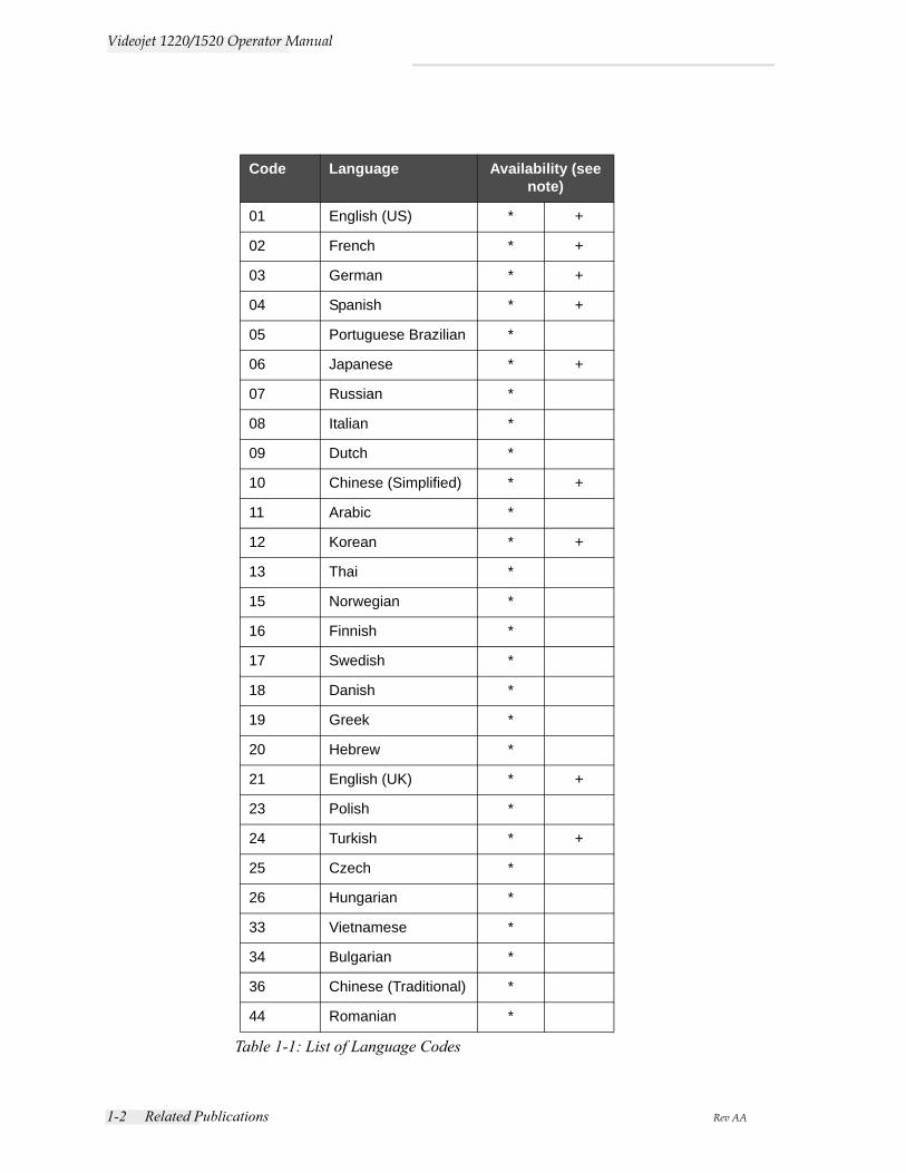
Language CodesWhen you order these manuals, make sure to add the 2-digit language code at the end of the part number. For example, the spanish version of the operator manual is part number 462268-04. Table 1-1 on page 1-2 shows the list of language codes that you can use to identify the translated versions of this manual.
Note: The availability of the Operator Manual is indicated by an asterisk (*). Availability of the Service Manual is indicated by a plus sign (+). For more information, contact the Videojet distributor or subsidiary.
1-2 Related Publications Rev AA
Videojet 1220/1520 Operator Manual
Code Language Availability (see note)
01 English (US) * +
02 French * +
03 German * +
04 Spanish * +
05 Portuguese Brazilian *
06 Japanese * +
07 Russian *
08 Italian *
09 Dutch *
10 Chinese (Simplified) * +
11 Arabic *
12 Korean * +
13 Thai *
15 Norwegian *
16 Finnish *
17 Swedish *
18 Danish *
19 Greek *
20 Hebrew *
21 English (UK) * +
23 Polish *
24 Turkish * +
25 Czech *
26 Hungarian *
33 Vietnamese *
34 Bulgarian *
36 Chinese (Traditional) *
44 Romanian *
Table 1-1: List of Language Codes
Rev AA Content Presentation 1-3
Videojet 1220/1520 Operator Manual
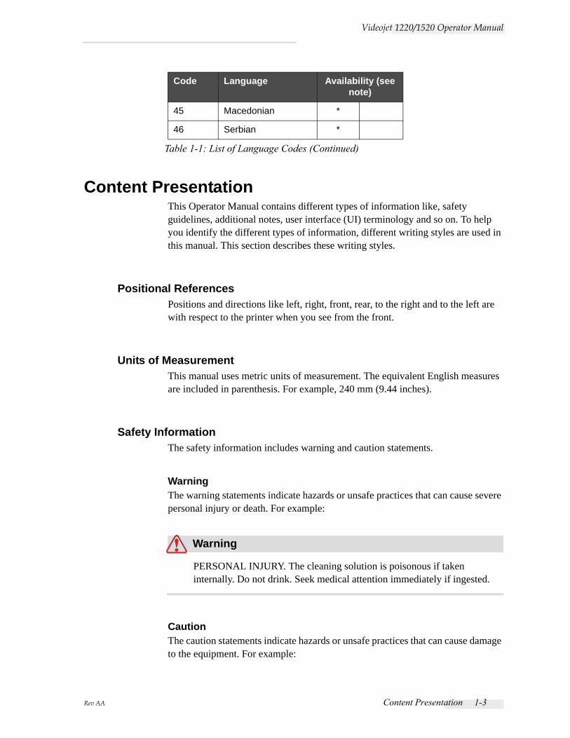
Content PresentationThis Operator Manual contains different types of information like, safety guidelines, additional notes, user interface (UI) terminology and so on. To help you identify the different types of information, different writing styles are used in this manual. This section describes these writing styles.
Positional ReferencesPositions and directions like left, right, front, rear, to the right and to the left are with respect to the printer when you see from the front.
Units of MeasurementThis manual uses metric units of measurement. The equivalent English measures are included in parenthesis. For example, 240 mm (9.44 inches).
Safety InformationThe safety information includes warning and caution statements.
WarningThe warning statements indicate hazards or unsafe practices that can cause severe personal injury or death. For example:
Warning
PERSONAL INJURY. The cleaning solution is poisonous if taken internally. Do not drink. Seek medical attention immediately if ingested.
CautionThe caution statements indicate hazards or unsafe practices that can cause damage to the equipment. For example:
45 Macedonian *
46 Serbian *
Code Language Availability (see note)
Table 1-1: List of Language Codes (Continued)
1-4 Content Presentation Rev AA
Videojet 1220/1520 Operator Manual
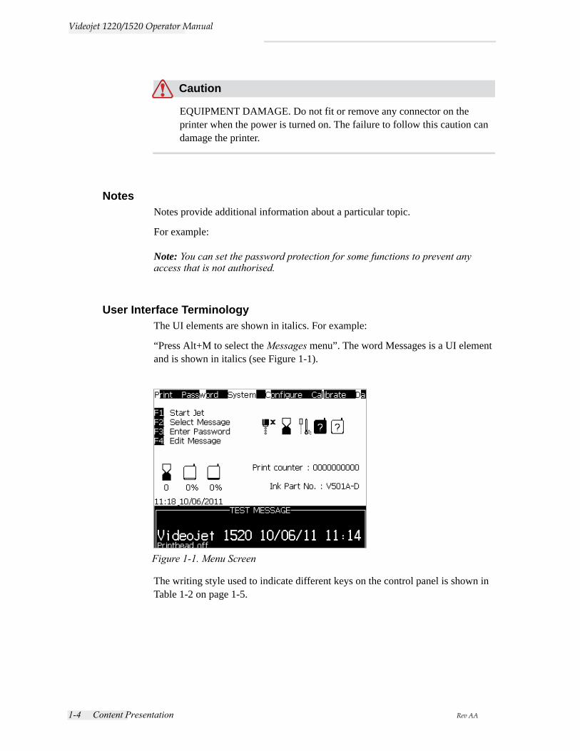
Caution
EQUIPMENT DAMAGE. Do not fit or remove any connector on the printer when the power is turned on. The failure to follow this caution can damage the printer.
NotesNotes provide additional information about a particular topic.
For example:
Note: You can set the password protection for some functions to prevent any access that is not authorised.
User Interface TerminologyThe UI elements are shown in italics. For example:
“Press Alt+M to select the Messages menu”. The word Messages is a UI element and is shown in italics (see Figure 1-1).
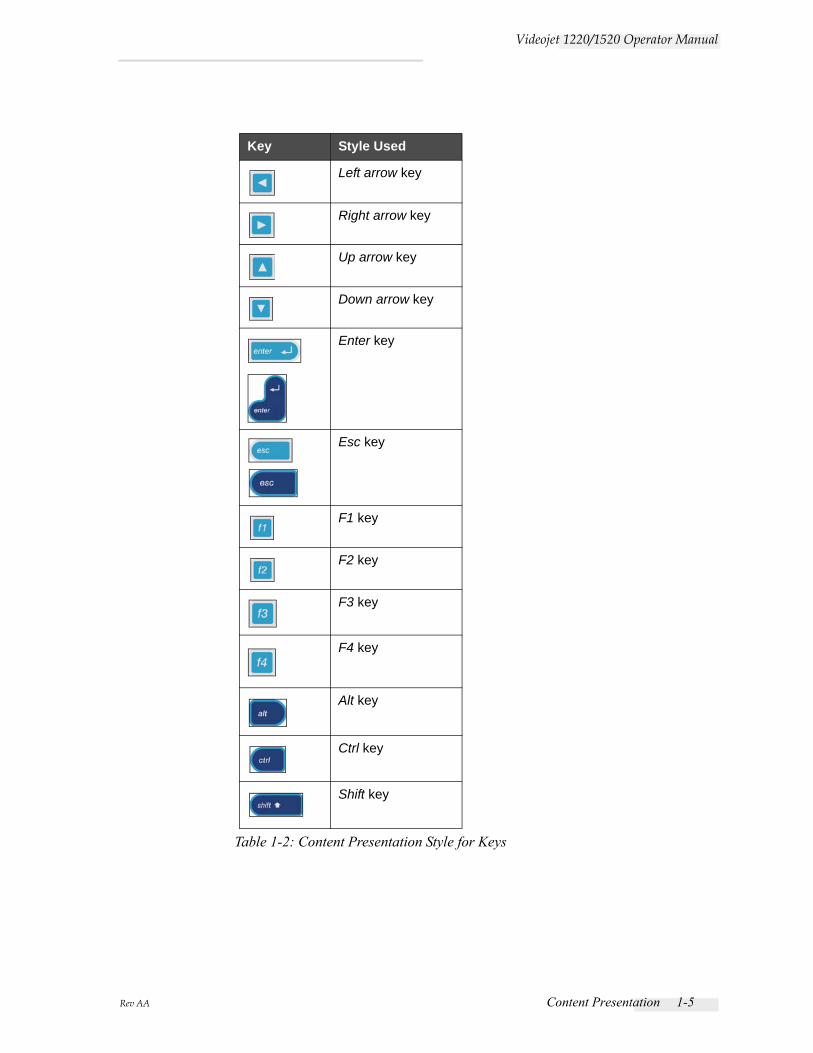
The writing style used to indicate different keys on the control panel is shown in Table 1-2 on page 1-5.
Figure 1-1. Menu Screen
Rev AA Content Presentation 1-5
Videojet 1220/1520 Operator Manual
Key Style Used
Left arrow key
Right arrow key
Up arrow key
Down arrow key
Enter key
Esc key
F1 key
F2 key
F3 key
F4 key
Alt key
Ctrl key
Shift key
Table 1-2: Content Presentation Style for Keys
1-6 Abbreviations and Acronyms Rev AA
Videojet 1220/1520 Operator Manual
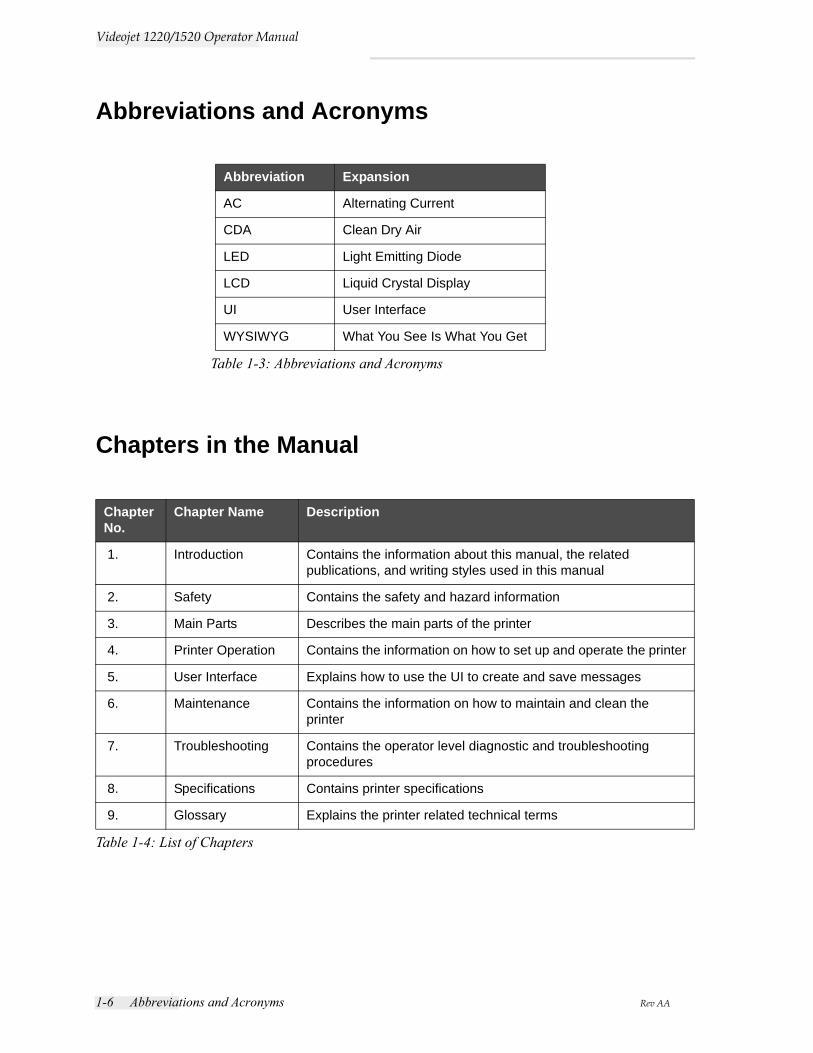
Abbreviations and Acronyms
Chapters in the Manual
Abbreviation Expansion
AC Alternating Current
CDA Clean Dry Air
LED Light Emitting Diode
LCD Liquid Crystal Display
UI User Interface
WYSIWYG What You See Is What You Get
Table 1-3: Abbreviations and Acronyms
Chapter No.
Chapter Name Description
1. Introduction Contains the information about this manual, the related publications, and writing styles used in this manual
2. Safety Contains the safety and hazard information
3. Main Parts Describes the main parts of the printer
4. Printer Operation Contains the information on how to set up and operate the printer
5. User Interface Explains how to use the UI to create and save messages
6. Maintenance Contains the information on how to maintain and clean the printer
7. Troubleshooting Contains the operator level diagnostic and troubleshooting procedures
8. Specifications Contains printer specifications
9. Glossary Explains the printer related technical terms
Table 1-4: List of Chapters
Rev AA Introduction 2-1
2Safety
IntroductionThe policy of Videojet Technologies Inc. is to manufacture non-contact printing/coding systems and ink supplies that meet high standards of performance and reliability. We enforce strict quality control techniques to eliminate potential defects and hazards in our products.
The intended use of the printer is to print information directly onto a product. Use of this equipment in any other fashion may lead to serious personal injury.
The safety guidelines provided in this chapter are intended to educate the operators on all safety issues so that the printer is serviced and operated in a safe manner.
General Safety Guidelines• Always refer to the correct service manuals as per the specific Videojet
printer model for important details.
• Only Videojet-trained personnel must carry out installation and maintenance work. Any such work undertaken by unauthorized personnel may damage the printer and will invalidate the warranty.
• To avoid damage to the printer components, use only soft brushes and lint free cloths for cleaning. Do not use high pressure air, cotton waste, or abrasive materials.
• The printhead must be completely dry before attempting to start the printer, otherwise the printhead may get damaged.
• Do not fit or remove any connector on the printer when the power is turned on, otherwise the printer may get damaged.
2-2 Electrical Safety Guidelines Rev AA
Videojet 1220/1520 Operator Manual
Electrical Safety GuidelinesThis section explains the safety guidelines related to electrical power supply and electrical cables.
Electrical Power Supply
Warning
PERSONAL INJURY. Lethal voltages are present within this equipment when it is connected to the mains electrical supply. Only trained and authorized personnel must carry out the maintenance work.
Warning
PERSONAL INJURY. Observe all statutory electrical safety codes and practices. Unless it is necessary to run the printer, disconnect the printer from the mains electrical supply before removing the covers or attempting any service or repair activity. Non-adherence to this warning can result in death or personal injury.
Warning
PERSONAL INJURY. A high AC voltage is present at the inverter and backlight. Extreme caution is required when diagnosing failure in these areas.

Rev AA Electrical Safety Guidelines 2-3
Videojet 1220/1520 Operator Manual
Electrical Cables
Warning
PERSONAL INJURY. Use only the main power cable supplied with the printer. The end of this cable must have an approved, three-pole, main plug that has a protective ground conductor.
The electrical power cables, sockets and plugs must be kept clean and dry.
For pluggable equipment, the socket-outlet must be installed near the equipment and must be easily accessible.
Warning
PERSONAL INJURY. Always inspect the cables for damage, wear, corrosion, and deterioration. Make all grounding/bonding connections void of areas of paint, ink build-up, and corrosion.
Grounding and Bonding
Warning
PERSONAL INJURY. The printer must be connected to an AC power supply that has a protective ground conductor and must be according to IEC requirements or applicable local regulations.
Warning
PERSONAL INJURY. Do not use the printer if there is any interruption in the protective ground conductor or if the protective ground conductor is disconnected. The failure to follow this warning can cause an electrical shock.
2-4 Electrical Safety Guidelines Rev AA
Videojet 1220/1520 Operator Manual
Warning
PERSONAL INJURY. Always ground conductive equipment to an earthing electrode or to the building grounding system with approved cables as per NEC standards in order to drain all potential static discharge. For example, a metal service tray to earth ground.
Warning
PERSONAL INJURY. A resistance reading from the grounded service tray to the equipment chassis or mounting bracket should be 0 to less than 1 ohm. A resistance check should be made using a safe and reliable ohmmeter and should be done on a frequent basis.
Warning
PERSONAL INJURY. The PCBs contain static sensitive devices. A suitably grounded, antistatic wrist strap must be worn when working on or handling PCBs.
Warning
PERSONAL INJURY. Always prevent static discharge from occurring. Use proper Grounding and Bonding methods. Only use Videojet approved metallic service trays and ground cables.
Warning
PERSONAL INJURY. Always bond conductive equipment together with approved cables to maintain them at the same potential and minimize static discharge. For example, printhead to metal service tray.
Rev AA Fluid Safety Guidelines 2-5
Videojet 1220/1520 Operator Manual
Warning
PERSONAL INJURY. The Optional Wash Station has been solely designed for the cleaning of the printhead.
Do not use it for purging or printing operations or for any other purposes.
Always ensure that the jet is stopped and that any hazardous voltages are switched off prior to the commencement of the printhead wash down.
Caution
EQUIPMENT DAMAGE. Always empty the service trays frequently. Some inks and cleaning solutions are flammable. Make sure that the waste fluids are disposed according to HAZMAT.
Fuses
Warning
PERSONAL INJURY. To ensure continued protection against fire hazards, replace fuses only with the specified type and rating.
Fluid Safety GuidelinesThis section describes the hazards that may occur while handling ink, make-up fluid, and cleaning solutions, and the safety precautions that a user must take to prevent the hazards.
Read the Material Safety Data SheetsRead and understand the Material Safety Data Sheet (MSDS) before using any ink, make-up fluid, or cleaning solution. An MSDS exists for each type of ink, make-up fluid, and cleaning solution. For more information, visit www.videojet.com and navigate to Documentation > Material Safety Data Sheets.

2-6 Fluid Safety Guidelines Rev AA
Videojet 1220/1520 Operator Manual
Ink and Make-up Fluid
Warning
PERSONAL INJURY. The ink and make-up fluid are irritating to the eyes and respiratory system. To prevent personal injury when handling these substances:
Always wear protective clothing and rubber gloves.
Always wear goggles with side-shields or a face mask. It is also advisable to wear safety glasses when carrying out maintenance.
Apply barrier hand cream before handling ink.
If ink or make-up fluid contaminates the skin, wash immediately with soap water. DO NOT use washdown or solvent to clean ink stains from the skin.
Warning
PERSONAL INJURY. The ink and make-up fluid are volatile and highly flammable. They must be stored and handled in accordance with local regulations.
Do not smoke or use a naked flame in the vicinity of these substances.
Immediately after use, remove any tissue or cloth that becomes saturated with these substances. Dispose all such items in accordance with the local regulations.
In the event that any ink or make-up fluid container is not completely empty after use, it should be resealed. Only full bottles are recommended for use when replenishing ink or make-up fluid; partially filled bottles must be disposed in accordance with the local regulations.
Warning
PERSONAL INJURY. When setting up the nozzle, direct the ink stream into a beaker or suitable container. To avoid the contamination of the ink, do not re-use any ink collected in this way. Dispose all waste ink in accordance with the local regulations.
Rev AA Fluid Safety Guidelines 2-7
Videojet 1220/1520 Operator Manual
Warning
PERSONAL INJURY. Prolonged breathing of make-up fluid or cleaning fluid vapor may cause drowsiness and/or effects similar to alcoholic intoxication. Use only in open, well-ventilated areas.
Cleaning Solution
Warning
PERSONAL INJURY. The cleaning solution is poisonous if taken internally. Do not drink. Seek medical attention immediately if ingested.
Warning
PERSONAL INJURY. The cleaning solution is irritating to the eyes and respiratory system. To prevent personal injury when handling this substance:
Always wear protective rubber gloves and clothing.
Always wear goggles with side-shields or a face mask. It is also advisable to wear safety glasses when carrying out maintenance.
Apply barrier hand cream before handling ink.
If cleaning solution contaminates the skin, rinse off with running water for at least 15 minutes.
Warning
PERSONAL INJURY. The cleaning solution is volatile and highly flammable. It must be stored and handled in accordance with local regulations.
Do not smoke or use a naked flame in the vicinity of the cleaning solution.
Immediately after use remove any tissue or cloths that become saturated with cleaning solution. Dispose all such items in accordance with local regulations.
2-8 Compressed Air Safety Guidelines Rev AA
Videojet 1220/1520 Operator Manual
Caution
EQUIPMENT DAMAGE. Ensure that the cleaning solution is compatible with the ink used before carrying out printhead cleaning otherwise the printhead may get damaged.
Caution
EQUIPMENT DAMAGE. Any cleaning solutions containing either chloride, including hypochlorite bleaches or hydrochloric acid, can cause unacceptable surface pitting and staining. These should not be used in contact with stainless steels. If wire brushes or wire scouring pads are used, these should be made of stainless steel. Make sure that any abrasive media used is free from sources of contamination, especially iron and chlorides.
Compressed Air Safety Guidelines
Warning
PERSONAL INJURY. Airborne particles and substances are a health hazard. Do not use high pressure compressed air for cleaning purposes.
UI Related Safety Guidelines
Caution
DATA SECURITY. To prevent unauthorized access to the software, ensure that Clear Password is executed when exiting from a higher level password.
Rev AA Other Important Guidelines 2-9
Videojet 1220/1520 Operator Manual
Caution
RISK OF DATA LOSS. Ensure the correct message name is selected for message deletion as no message selection confirmation prompt is given. All messages apart from the TEST MESSAGE will be deleted when you select the Delete All Messages option.
Caution
RISK OF DATA LOSS. The Delete User Field option does not ask for confirmation to delete a User Field.
Other Important Guidelines
Caution
EQUIPMENT DAMAGE. After a Quick Stop, the machine should not be left in this state for any length of time as drying ink may make restarting difficult.
Caution
EQUIPMENT DAMAGE. The printhead must be completely dry before attempting to start the printer otherwise the EHT will trip.
Warning
PERSONAL INJURY. If the battery is replaced by an incorrect type, it will lead to an explosion. Always dispose off the used batteries according to the instructions and local regulations.
2-10 Other Important Guidelines Rev AA
Videojet 1220/1520 Operator Manual
Warning
PERSONAL INJURY. In a fault condition, heater can reach 70 oC. Do not touch the plate on which the heater is mounted. The failure to follow this warning can cause personal injury.
Rev AA Videojet 1220/1520 Printer 3-1
3Main Parts
Videojet 1220/1520 Printer
5
43
2
1
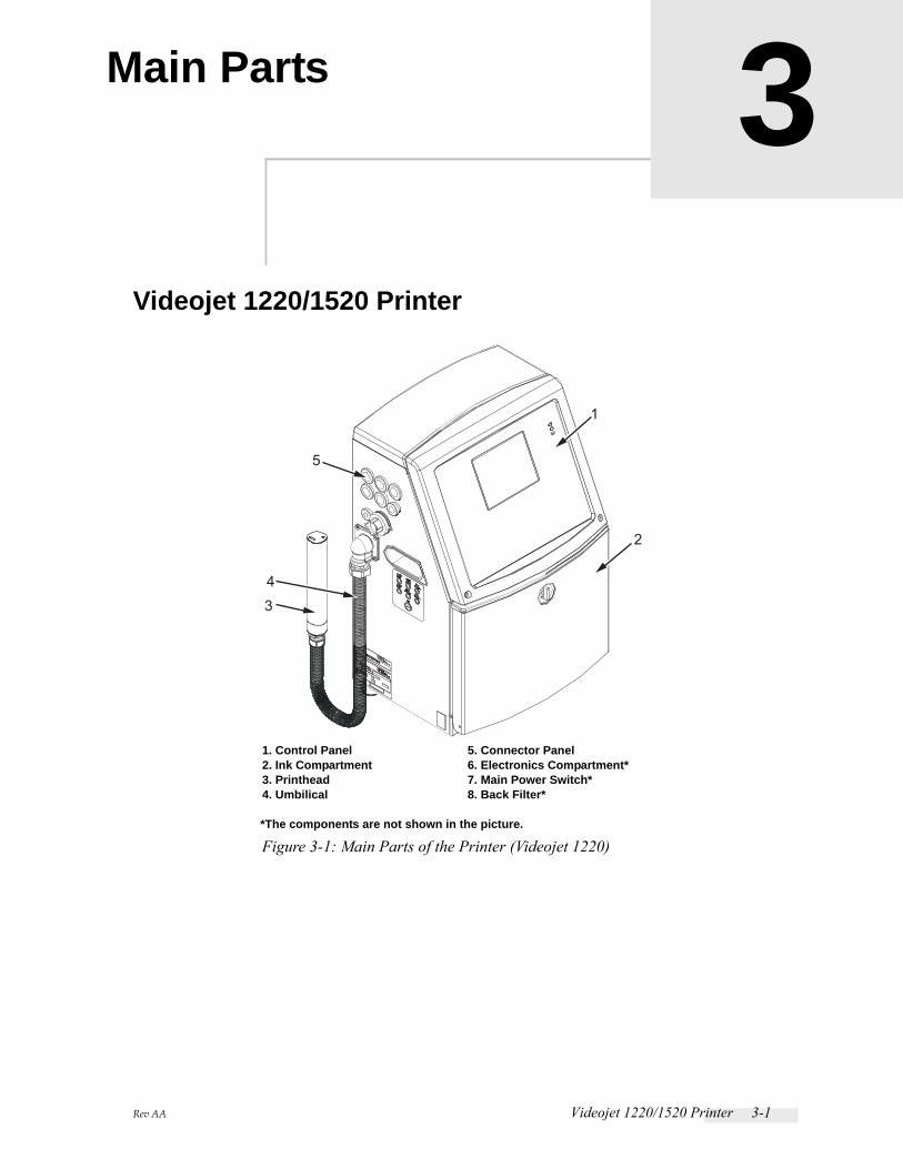
Figure 3-1: Main Parts of the Printer (Videojet 1220)
1. Control Panel2. Ink Compartment3. Printhead4. Umbilical
5. Connector Panel 6. Electronics Compartment*7. Main Power Switch*8. Back Filter*
*The components are not shown in the picture.
3-2 Videojet 1220/1520 Printer Rev AA
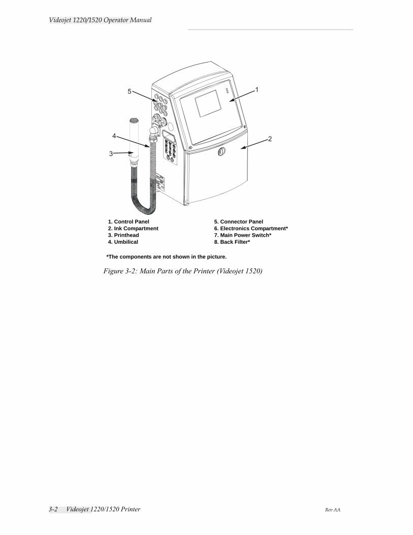
Videojet 1220/1520 Operator Manual
1
24
5
3
1. Control Panel2. Ink Compartment3. Printhead4. Umbilical
5. Connector Panel6. Electronics Compartment*7. Main Power Switch*8. Back Filter*
*The components are not shown in the picture.
Figure 3-2: Main Parts of the Printer (Videojet 1520)
Rev AA Control Panel 3-3
Videojet 1220/1520 Operator Manual
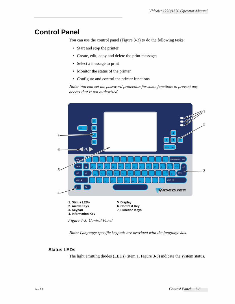
Control PanelYou can use the control panel (Figure 3-3) to do the following tasks:
• Start and stop the printer
• Create, edit, copy and delete the print messages
• Select a message to print
• Monitor the status of the printer
• Configure and control the printer functions
Note: You can set the password protection for some functions to prevent any access that is not authorised.
Note: Language specific keypads are provided with the language kits.
Status LEDsThe light emitting diodes (LEDs) (item 1, Figure 3-3) indicate the system status.
1
2
3
4
6
5
7
1. Status LEDs2. Arrow Keys3. Keypad4. Information Key
5. Display6. Contrast Key7. Function Keys
Figure 3-3: Control Panel
3-4 Control Panel Rev AA
Videojet 1220/1520 Operator Manual
Arrow KeysThe arrow keys (item 2) allow the operator to navigate through the software menus.
KeypadThe keypad (item 3) is 72 key, QWERTY, membrane type with tactile response keys. The solvents that you use for printing and maintenance do not damage the keypad.
DisplayThe Quarter Video Graphics Array (QVGA) Liquid Crystal Display (LCD) (item 5) has a resolution of 320 x 240 pixels. The LCD has an LED backlight to help you see in low light conditions.
Contrast Keys
The contrast keys (item 6) help the operator to increase or decrease the contrast of the LCD.
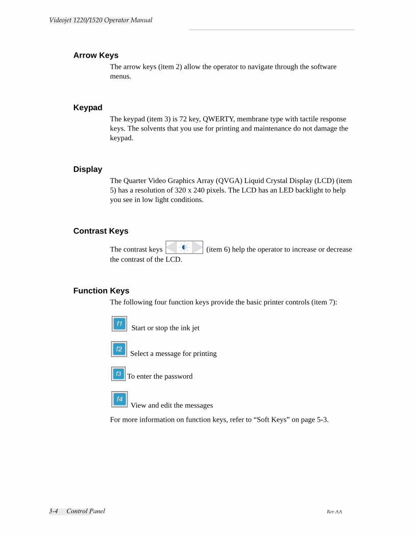
Function KeysThe following four function keys provide the basic printer controls (item 7):
Start or stop the ink jet
Select a message for printing
To enter the password
View and edit the messages
For more information on function keys, refer to “Soft Keys” on page 5-3.
Rev AA Control Panel 3-5
Videojet 1220/1520 Operator Manual
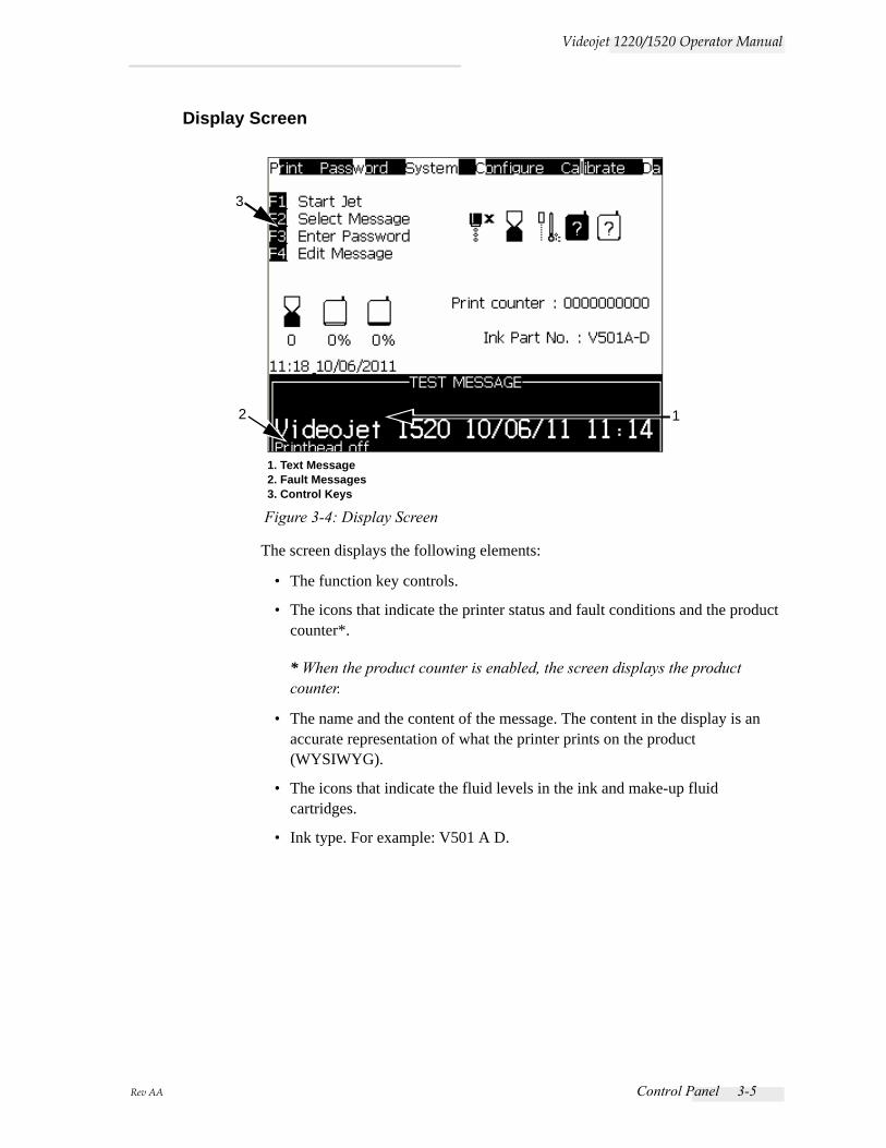
Display Screen
The screen displays the following elements:
• The function key controls.
• The icons that indicate the printer status and fault conditions and the product counter*.
* When the product counter is enabled, the screen displays the product counter.
• The name and the content of the message. The content in the display is an accurate representation of what the printer prints on the product (WYSIWYG).
• The icons that indicate the fluid levels in the ink and make-up fluid cartridges.
• Ink type. For example: V501 A D.
Figure 3-4: Display Screen
2 1
3
1. Text Message2. Fault Messages3. Control Keys
3-6 Electronics Compartment Rev AA
Videojet 1220/1520 Operator Manual
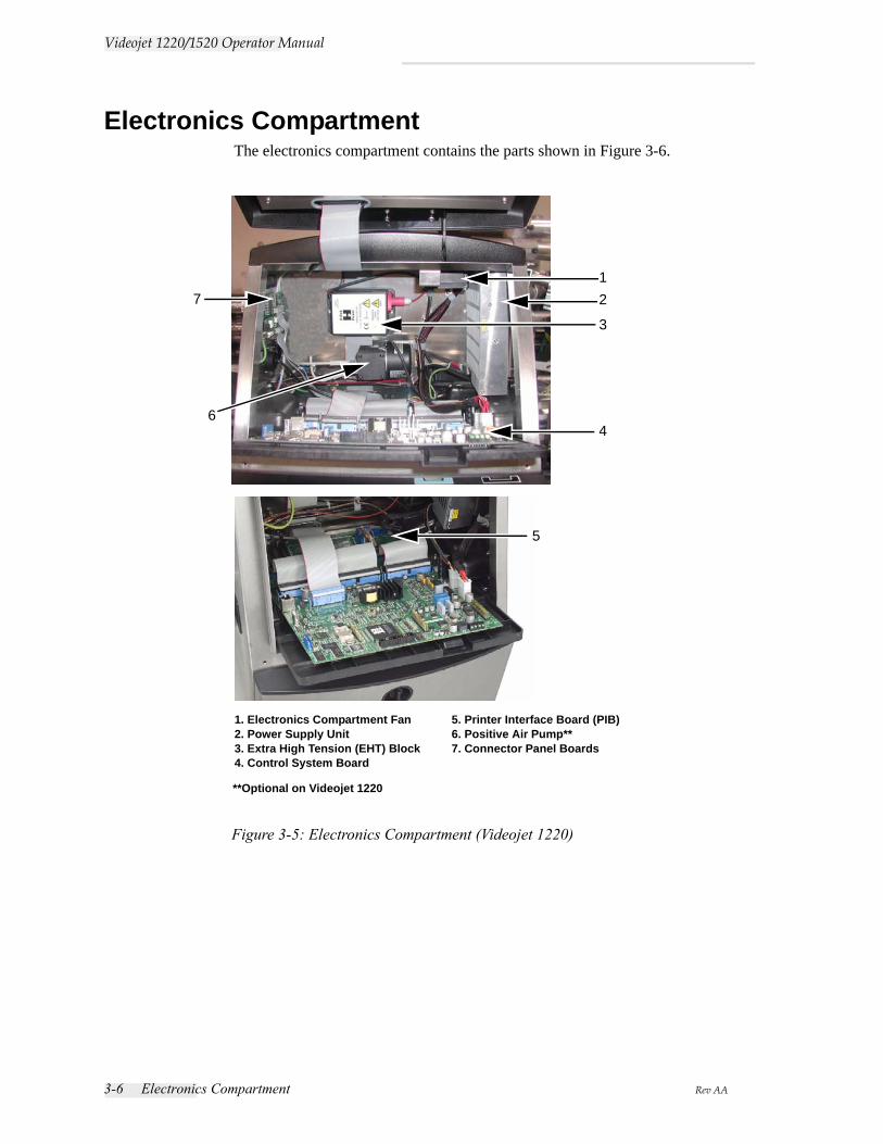
Electronics CompartmentThe electronics compartment contains the parts shown in Figure 3-6.
1. Electronics Compartment Fan2. Power Supply Unit3. Extra High Tension (EHT) Block4. Control System Board
5. Printer Interface Board (PIB)6. Positive Air Pump**7. Connector Panel Boards
2
4
3
5
Figure 3-5: Electronics Compartment (Videojet 1220)
71
6
**Optional on Videojet 1220
Rev AA Electronics Compartment 3-7
Videojet 1220/1520 Operator Manual
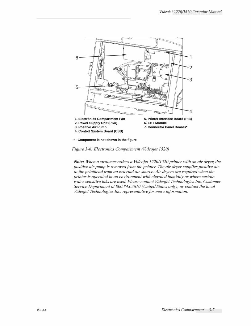
Note: When a customer orders a Videojet 1220/1520 printer with an air dryer, the positive air pump is removed from the printer. The air dryer supplies positive air to the printhead from an external air source. Air dryers are required when the printer is operated in an environment with elevated humidity or where certain water sensitive inks are used. Please contact Videojet Technologies Inc. Customer Service Department at 800.843.3610 (United States only), or contact the local Videojet Technologies Inc. representative for more information.
1
2
3
4
5
6
1. Electronics Compartment Fan2. Power Supply Unit (PSU)3. Positive Air Pump4. Control System Board (CSB)
5. Printer Interface Board (PIB)6. EHT Module7. Connector Panel Boards*
* - Component is not shown in the figure
Figure 3-6: Electronics Compartment (Videojet 1520)
3-8 Ink Compartment Rev AA
Videojet 1220/1520 Operator Manual
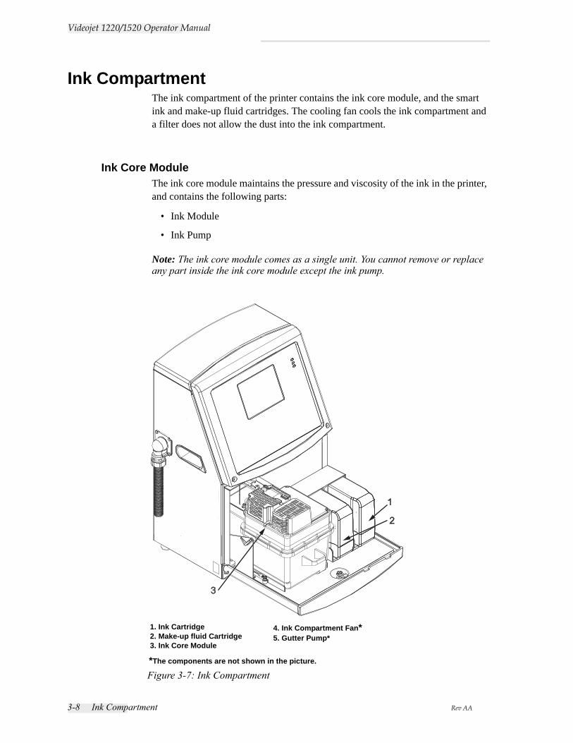
Ink CompartmentThe ink compartment of the printer contains the ink core module, and the smart ink and make-up fluid cartridges. The cooling fan cools the ink compartment and a filter does not allow the dust into the ink compartment.
Ink Core ModuleThe ink core module maintains the pressure and viscosity of the ink in the printer, and contains the following parts:
• Ink Module
• Ink Pump
Note: The ink core module comes as a single unit. You cannot remove or replace any part inside the ink core module except the ink pump.
Figure 3-7: Ink Compartment
1. Ink Cartridge2. Make-up fluid Cartridge3. Ink Core Module
4. Ink Compartment Fan*5. Gutter Pump*
*The components are not shown in the picture.
Rev AA Printhead and Umbilical 3-9
Videojet 1220/1520 Operator Manual
Smart Cartridge
Note: Refer to “Replace Smart Cartridges” on page 6-4 to replace the cartridges.
The smart cartridges use the smart chip technology to ensure the proper and in shelf-life ink and make-up fluids are used.
Ink Compartment FanThe ink compartment fan cools the ink module and the ink pump.
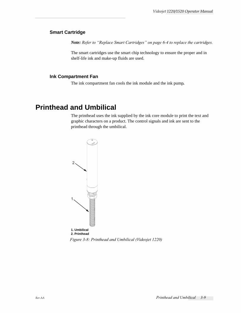
Printhead and UmbilicalThe printhead uses the ink supplied by the ink core module to print the text and graphic characters on a product. The control signals and ink are sent to the printhead through the umbilical.
1
2
Figure 3-8: Printhead and Umbilical (Videojet 1220)
1. Umbilical2. Printhead

3-10 Printhead and Umbilical Rev AA
Videojet 1220/1520 Operator Manual
2
1
1. Umbilical2. Printhead
Figure 3-9: Printhead and Umbilical (Videojet 1520)
12
1. Umbilical2. Printhead
90° Printhead
Figure 3-10: Printhead and Umbilical (Videojet 1220)
Rev AA Connector Panel 3-11
Videojet 1220/1520 Operator Manual
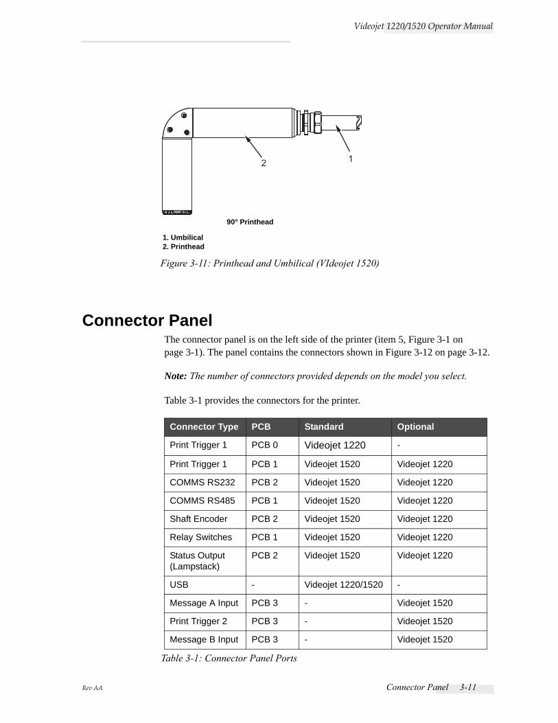
Connector PanelThe connector panel is on the left side of the printer (item 5, Figure 3-1 on page 3-1). The panel contains the connectors shown in Figure 3-12 on page 3-12.
Note: The number of connectors provided depends on the model you select.
Table 3-1 provides the connectors for the printer.
Connector Type PCB Standard Optional
Print Trigger 1 PCB 0 Videojet 1220 -
Print Trigger 1 PCB 1 Videojet 1520 Videojet 1220
COMMS RS232 PCB 2 Videojet 1520 Videojet 1220
COMMS RS485 PCB 1 Videojet 1520 Videojet 1220
Shaft Encoder PCB 2 Videojet 1520 Videojet 1220
Relay Switches PCB 1 Videojet 1520 Videojet 1220
Status Output(Lampstack)
PCB 2 Videojet 1520 Videojet 1220
USB - Videojet 1220/1520 -
Message A Input PCB 3 - Videojet 1520
Print Trigger 2 PCB 3 - Videojet 1520
Message B Input PCB 3 - Videojet 1520
Table 3-1: Connector Panel Ports
2 1
90° Printhead
1. Umbilical2. Printhead
Figure 3-11: Printhead and Umbilical (VIdeojet 1520)
3-12 Connector Panel Rev AA
Videojet 1220/1520 Operator Manual
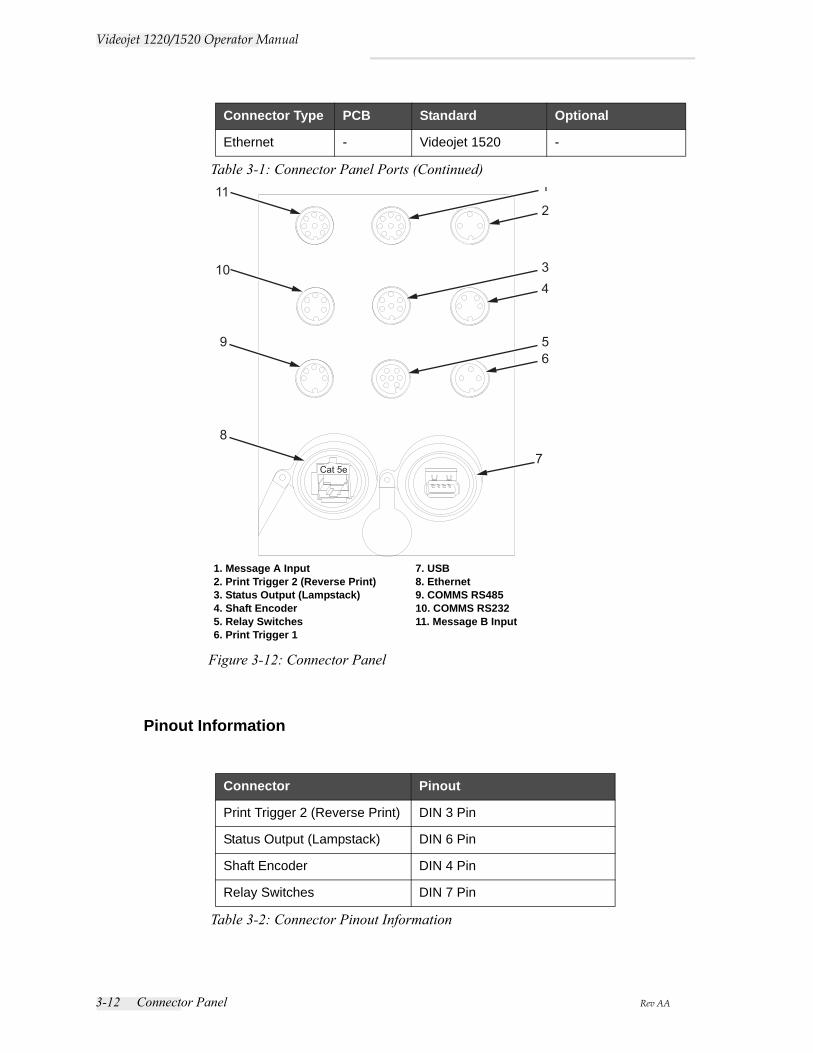
Pinout Information
Ethernet - Videojet 1520 -
Connector Pinout
Print Trigger 2 (Reverse Print) DIN 3 Pin
Status Output (Lampstack) DIN 6 Pin
Shaft Encoder DIN 4 Pin
Relay Switches DIN 7 Pin
Table 3-2: Connector Pinout Information
Connector Type PCB Standard Optional
Table 3-1: Connector Panel Ports (Continued)
1. Message A Input2. Print Trigger 2 (Reverse Print)3. Status Output (Lampstack)4. Shaft Encoder5. Relay Switches6. Print Trigger 1
7. USB8. Ethernet9. COMMS RS48510. COMMS RS23211. Message B Input
Figure 3-12: Connector Panel
Cat 5e
1
2
34
56
7
8
9
10
11
Rev AA Main Power Switch 3-13
Videojet 1220/1520 Operator Manual
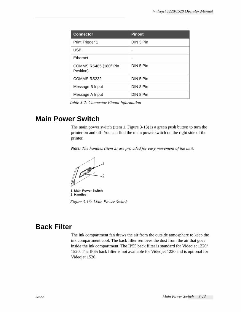
Main Power SwitchThe main power switch (item 1, Figure 3-13) is a green push button to turn the printer on and off. You can find the main power switch on the right side of the printer.
Note: The handles (item 2) are provided for easy movement of the unit.
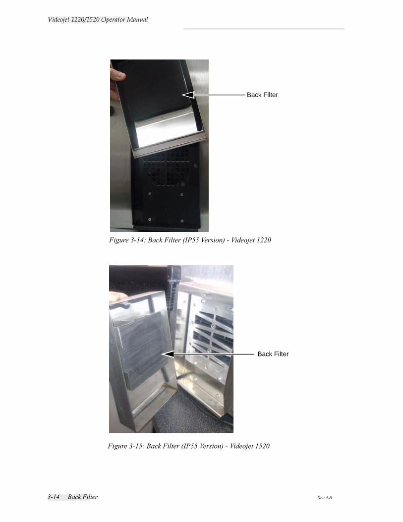
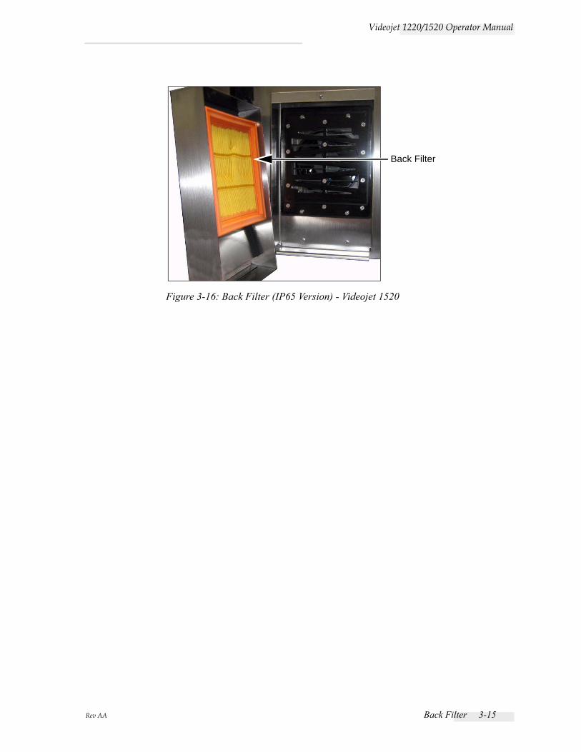
Back FilterThe ink compartment fan draws the air from the outside atmosphere to keep the ink compartment cool. The back filter removes the dust from the air that goes inside the ink compartment. The IP55 back filter is standard for Videojet 1220/1520. The IP65 back filter is not available for Videojet 1220 and is optional for Videojet 1520.
Print Trigger 1 DIN 3 Pin
USB -
Ethernet -
COMMS RS485 (180° Pin Position)
DIN 5 Pin
COMMS RS232 DIN 5 Pin
Message B Input DIN 8 Pin
Message A Input DIN 8 Pin
Connector Pinout
Table 3-2: Connector Pinout Information
1
2
Figure 3-13: Main Power Switch
1. Main Power Switch2. Handles
3-14 Back Filter Rev AA
Videojet 1220/1520 Operator Manual
Figure 3-14: Back Filter (IP55 Version) - Videojet 1220
Back Filter
Figure 3-15: Back Filter (IP55 Version) - Videojet 1520
Back Filter
Rev AA Back Filter 3-15
Videojet 1220/1520 Operator Manual
Figure 3-16: Back Filter (IP65 Version) - Videojet 1520
Back Filter
Rev AA Introduction 4-1
4Printer Operation
IntroductionThis chapter provides the procedures to do the following tasks:
• Turn on the printer
• Clean start and stop the printer
• Turn off the printer
• Create a message
• Print the messages
• System menu
• Calibrate menu
• Data logging menu
• Product counter
• Run hours
• Configure serial port
• Configure ethernet
• High speed remote data transfer
• Enter service information
• Printer configuration
• Create custom font
How to Turn on the PrinterDo the following tasks to turn on the printer:
1 Do the visual inspection.
2 Make sure that the electrical supply for the printer is available.
3 Press the main power switch to turn on the printer.
4-2 How to Clean Start and Stop the Printer Rev AA
Videojet 1220/1520 Operator Manual
How to Clean Start and Stop the PrinterThe default procedures to start and stop the printer are the Clean Start and the Clean Stop.
Note: If the Clean Start or the Clean Stop are not available, the printer requires a Quick Start or Quick Stop.(press Ctrl+ F1 for Quick Start and Quick Stop)The printer cannot provide the Clean Start and the Clean Stop options if the make-up fluid is empty or if the ink core level is high. Make sure that the make-up fluid is not empty or the ink core level is not high.
Caution
EQUIPMENT DAMAGE. Do not perform the Clean Start or the Clean Stop many times. The failure to follow this caution can cause high use of flush and dilution of the ink. The diluted ink decreases the quality of the print.
How to Clean StartPress the F1 key to start the jet start sequence.
The printer turns on the ink and the ink jet starts.
Note: To stop the ink jet, press the F1 key.
How to Clean StopPress the F1 key. The printer stops the flow of ink.
How to Set the PasswordsThe passwords are set and configured from the Password menu in the UI.
The UI has the following access levels:
• The level 0 is the default password level.
• The levels 1 and 2 are password protected. The customer can configure the two levels. The customer can use the two levels to access different menus in the UI. To set the passwords for the two levels, you must access the system at same access level or one level higher.

Rev AA How to Set the Passwords 4-3
Videojet 1220/1520 Operator Manual
How to Login for the First TimeDo the following tasks to login for the first time:
1 Open the Menu screen. The screen appears in level 0 with basic functions.
2 Press Alt + w. Select the Enter Password (see Figure 4-2) option and press the Enter key. Alternatively, press F3 in the Main screen. The Enter Password screen appears (see Figure 4-3).
3 Log in at level 1 (default password = 1111) or level 2 (default password = 2222) password. The current password level changes to selected password level from level 0.
How to Set the Passwords for Levels 1 and 2Do the following tasks to set the passwords for levels 1 and 2:
1 Press Alt + w and select Set Password for level 1 or Set Password for level 2 from the Password menu (see Figure 4-4). The New Password dialog box appears (see Figure 4-5).
Figure 4-1: Password Menu
Figure 4-2: Enter Password
Figure 4-3: Level 0 Password
4-4 How to Set the Passwords Rev AA
Videojet 1220/1520 Operator Manual
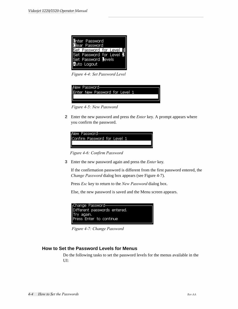
2 Enter the new password and press the Enter key. A prompt appears where you confirm the password.
3 Enter the new password again and press the Enter key.
If the confirmation password is different from the first password entered, the Change Password dialog box appears (see Figure 4-7).
Press Esc key to return to the New Password dialog box.
Else, the new password is saved and the Menu screen appears.
How to Set the Password Levels for MenusDo the following tasks to set the password levels for the menus available in the UI:
Figure 4-4: Set Password Level
Figure 4-5: New Password
Figure 4-6: Confirm Password
Figure 4-7: Change Password
Rev AA How to Set the Passwords 4-5
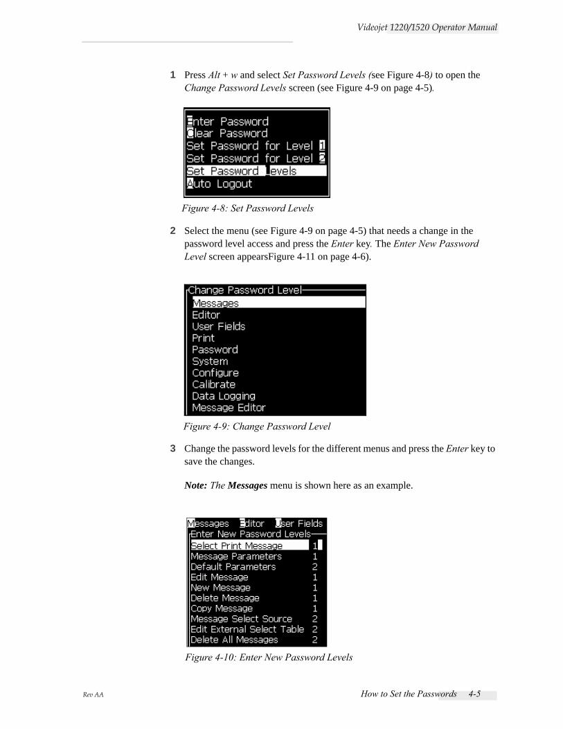
Videojet 1220/1520 Operator Manual
1 Press Alt + w and select Set Password Levels (see Figure 4-8) to open the Change Password Levels screen (see Figure 4-9 on page 4-5).
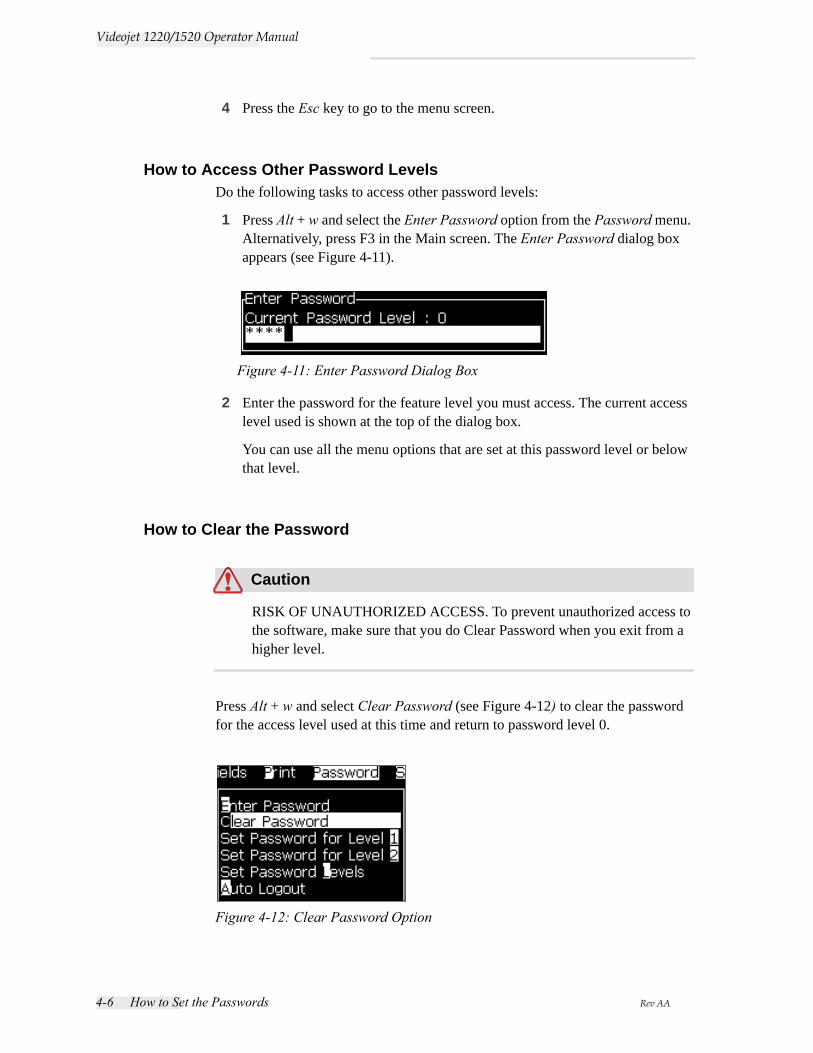
2 Select the menu (see Figure 4-9 on page 4-5) that needs a change in the password level access and press the Enter key. The Enter New Password Level screen appearsFigure 4-11 on page 4-6).
3 Change the password levels for the different menus and press the Enter key to save the changes.
Note: The Messages menu is shown here as an example.
Figure 4-8: Set Password Levels
Figure 4-9: Change Password Level
Figure 4-10: Enter New Password Levels
4-6 How to Set the Passwords Rev AA
Videojet 1220/1520 Operator Manual
4 Press the Esc key to go to the menu screen.
How to Access Other Password LevelsDo the following tasks to access other password levels:
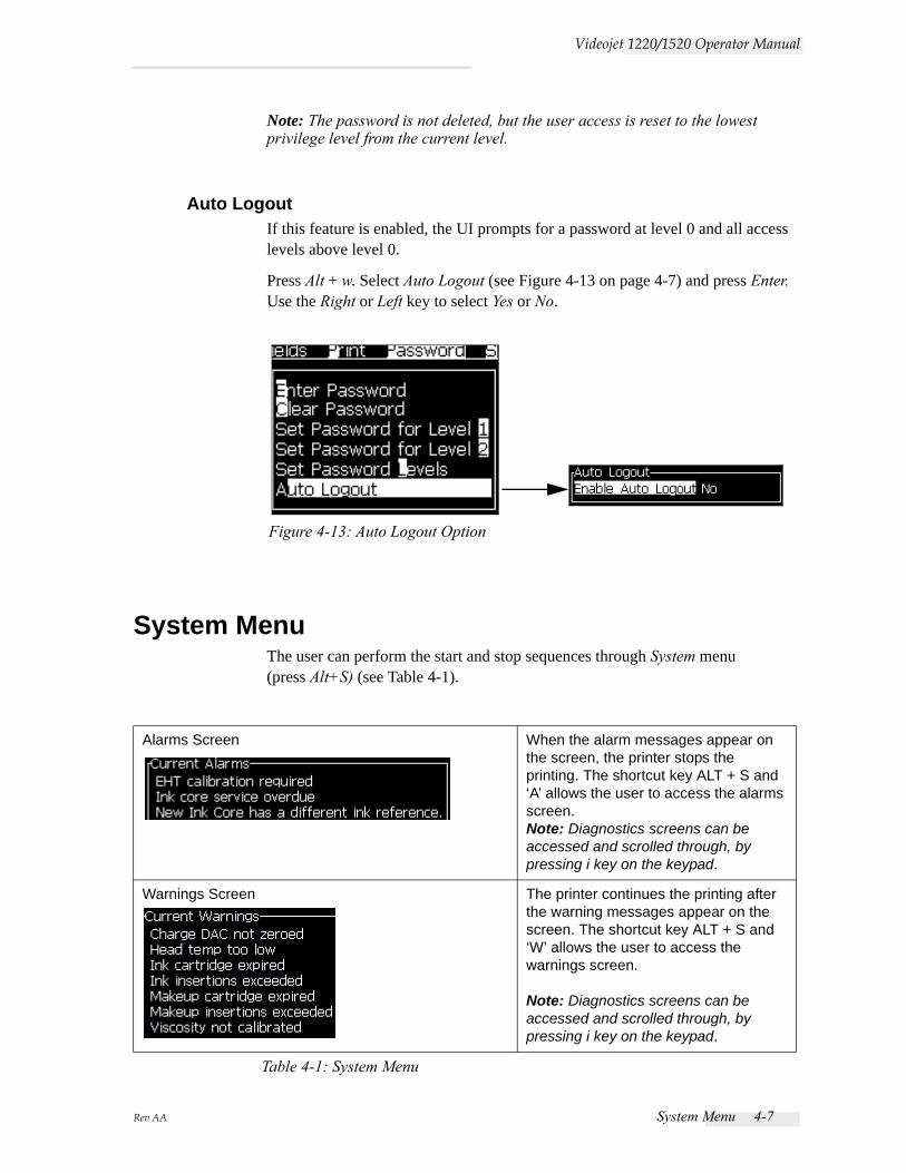
1 Press Alt + w and select the Enter Password option from the Password menu. Alternatively, press F3 in the Main screen. The Enter Password dialog box appears (see Figure 4-11).
2 Enter the password for the feature level you must access. The current access level used is shown at the top of the dialog box.
You can use all the menu options that are set at this password level or below that level.
How to Clear the Password
Caution
RISK OF UNAUTHORIZED ACCESS. To prevent unauthorized access to the software, make sure that you do Clear Password when you exit from a higher level.
Press Alt + w and select Clear Password (see Figure 4-12) to clear the password for the access level used at this time and return to password level 0.
Figure 4-11: Enter Password Dialog Box
Figure 4-12: Clear Password Option
Rev AA System Menu 4-7
Videojet 1220/1520 Operator Manual
Note: The password is not deleted, but the user access is reset to the lowest privilege level from the current level.
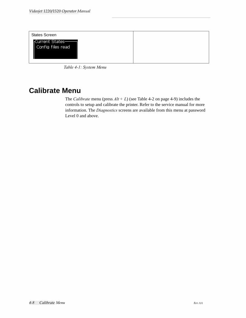
Auto LogoutIf this feature is enabled, the UI prompts for a password at level 0 and all access levels above level 0.
Press Alt + w. Select Auto Logout (see Figure 4-13 on page 4-7) and press Enter. Use the Right or Left key to select Yes or No.
System MenuThe user can perform the start and stop sequences through System menu (press Alt+S) (see Table 4-1).
Alarms Screen When the alarm messages appear on the screen, the printer stops the printing. The shortcut key ALT + S and ‘A’ allows the user to access the alarms screen.Note: Diagnostics screens can be accessed and scrolled through, by pressing i key on the keypad.
Warnings Screen The printer continues the printing after the warning messages appear on the screen. The shortcut key ALT + S and ‘W’ allows the user to access the warnings screen.
Note: Diagnostics screens can be accessed and scrolled through, by pressing i key on the keypad.
Table 4-1: System Menu
Figure 4-13: Auto Logout Option
4-8 Calibrate Menu Rev AA
Videojet 1220/1520 Operator Manual
Calibrate MenuThe Calibrate menu (press Alt + L) (see Table 4-2 on page 4-9) includes the controls to setup and calibrate the printer. Refer to the service manual for more information. The Diagnostics screens are available from this menu at password Level 0 and above.
States Screen
Table 4-1: System Menu
Rev AA Calibrate Menu 4-9
Videojet 1220/1520 Operator Manual
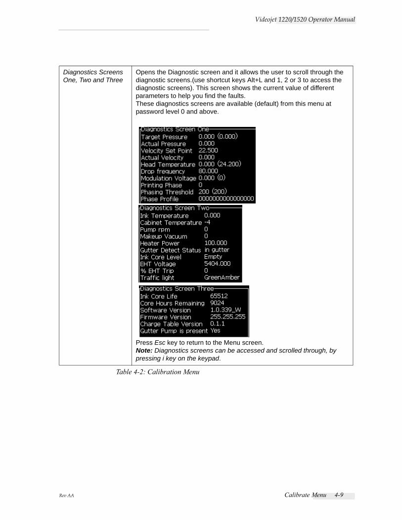
Diagnostics Screens One, Two and Three
Opens the Diagnostic screen and it allows the user to scroll through the diagnostic screens.(use shortcut keys Alt+L and 1, 2 or 3 to access the diagnostic screens). This screen shows the current value of different parameters to help you find the faults.These diagnostics screens are available (default) from this menu at password level 0 and above.
Press Esc key to return to the Menu screen.Note: Diagnostics screens can be accessed and scrolled through, by pressing i key on the keypad.
Table 4-2: Calibration Menu
4-10 Data Logging Menu Rev AA
Videojet 1220/1520 Operator Manual
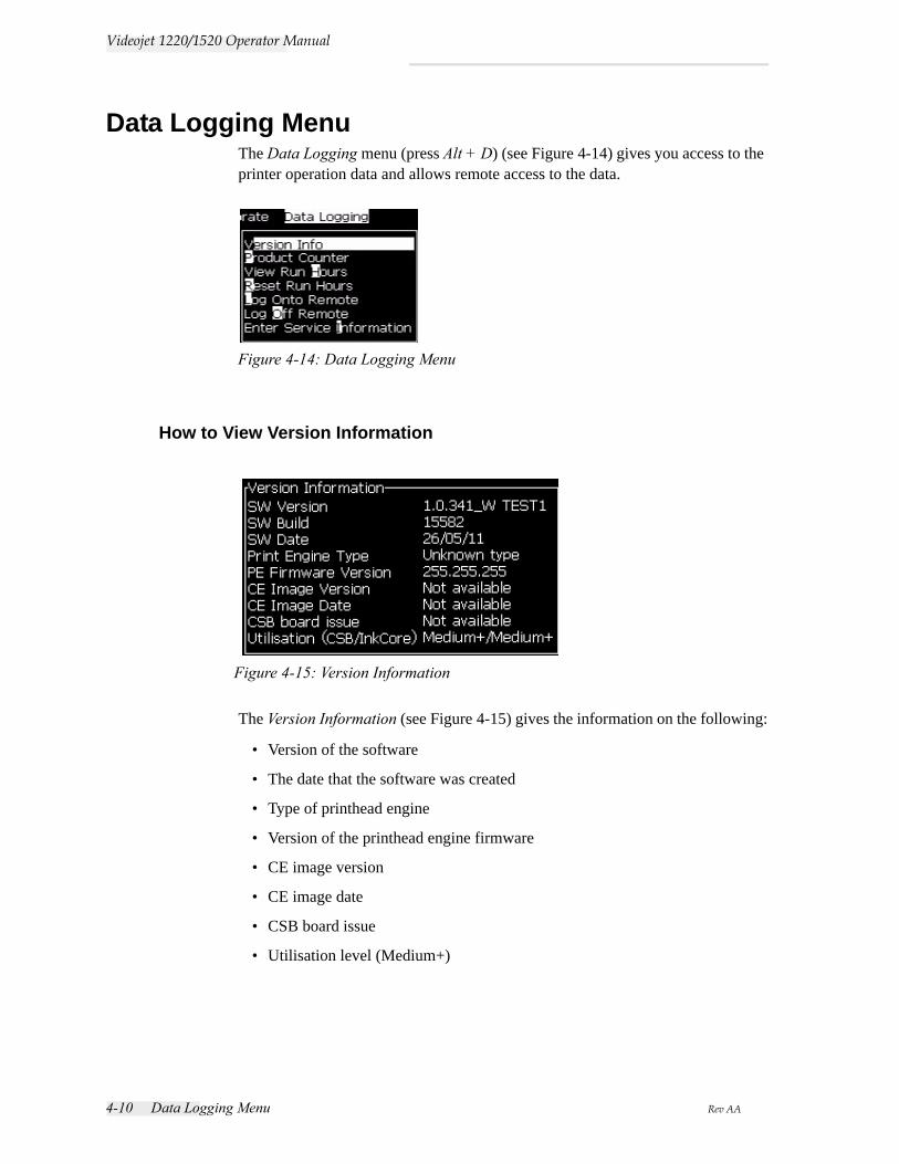
Data Logging MenuThe Data Logging menu (press Alt + D) (see Figure 4-14) gives you access to the printer operation data and allows remote access to the data.
How to View Version Information
The Version Information (see Figure 4-15) gives the information on the following:
• Version of the software
• The date that the software was created
• Type of printhead engine
• Version of the printhead engine firmware
• CE image version
• CE image date
• CSB board issue
• Utilisation level (Medium+)
Figure 4-14: Data Logging Menu
Figure 4-15: Version Information
Rev AA Product Counter 4-11
Videojet 1220/1520 Operator Manual
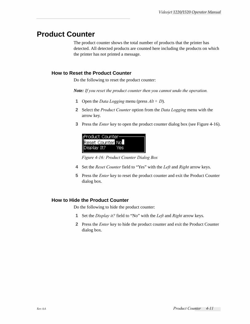
Product CounterThe product counter shows the total number of products that the printer has detected. All detected products are counted here including the products on which the printer has not printed a message.
How to Reset the Product CounterDo the following to reset the product counter:
Note: If you reset the product counter then you cannot undo the operation.
1 Open the Data Logging menu (press Alt + D).
2 Select the Product Counter option from the Data Logging menu with the arrow key.
3 Press the Enter key to open the product counter dialog box (see Figure 4-16).
4 Set the Reset Counter field to “Yes” with the Left and Right arrow keys.
5 Press the Enter key to reset the product counter and exit the Product Counter dialog box.
How to Hide the Product CounterDo the following to hide the product counter:
1 Set the Display it? field to “No” with the Left and Right arrow keys.
2 Press the Enter key to hide the product counter and exit the Product Counter dialog box.
Figure 4-16: Product Counter Dialog Box
4-12 Run Hours Rev AA
Videojet 1220/1520 Operator Manual
Run Hours
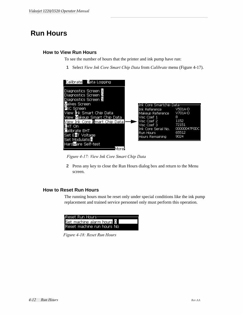
How to View Run HoursTo see the number of hours that the printer and ink pump have run:
1 Select View Ink Core Smart Chip Data from Calibrate menu (Figure 4-17).
2 Press any key to close the Run Hours dialog box and return to the Menu screen.
How to Reset Run HoursThe running hours must be reset only under special conditions like the ink pump replacement and trained service personnel only must perform this operation.
Figure 4-17: View Ink Core Smart Chip Data
Figure 4-18: Reset Run Hours
Rev AA How to Configure the Serial Port 4-13
Videojet 1220/1520 Operator Manual
How to Configure the Serial PortThe RS-232 and RS-485 serial communication ports are optional features for Videojet 1220 printer and standard for Videojet 1520 printer. For more information, contact the Videojet distributor or subsidiary.
You can prepare the printer communication ports for the transmission of data logging information between the port and a remote device.
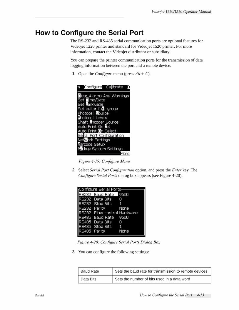
1 Open the Configure menu (press Alt + C).
2 Select Serial Port Configuration option, and press the Enter key. The Configure Serial Ports dialog box appears (see Figure 4-20).
3 You can configure the following settings:
Baud Rate Sets the baud rate for transmission to remote devices
Data Bits Sets the number of bits used in a data word
Figure 4-19: Configure Menu
Figure 4-20: Configure Serial Ports Dialog Box
4-14 How to Configure Ethernet Port Rev AA
Videojet 1220/1520 Operator Manual
4 Press the Enter key, when you complete the port configuration.
How to Configure Ethernet PortRefer to WSI/ESI Communications Protocol addendum for more information.
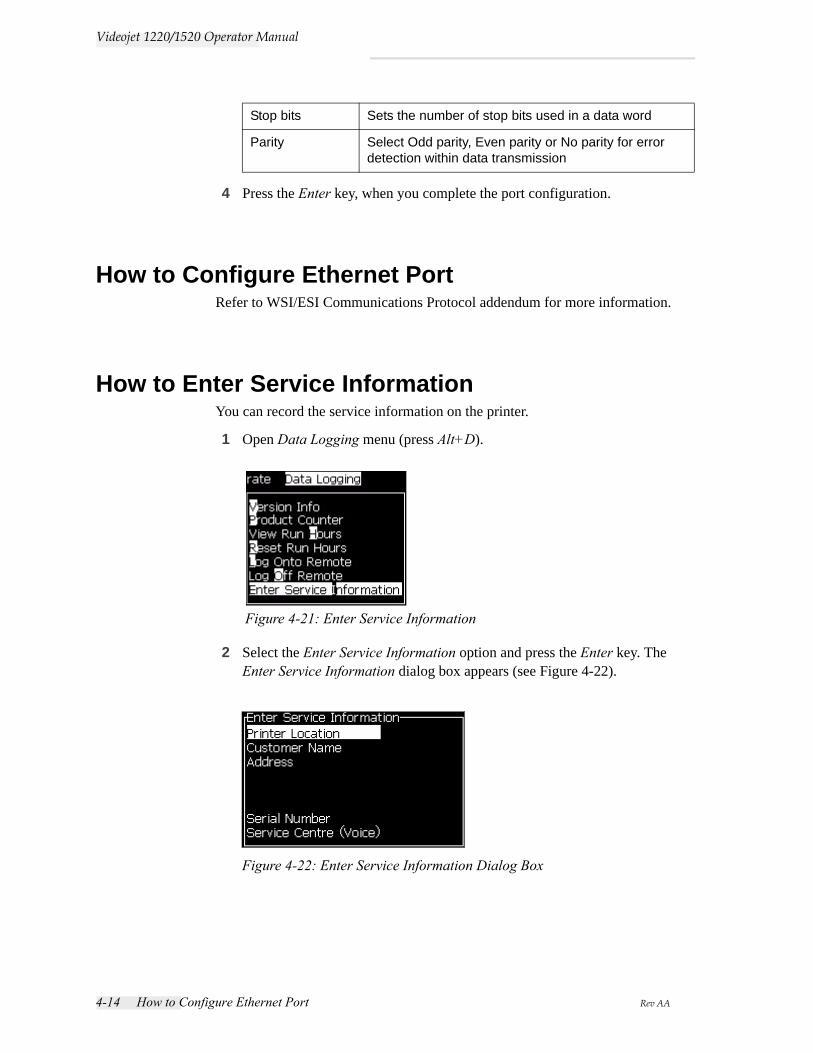
How to Enter Service InformationYou can record the service information on the printer.
1 Open Data Logging menu (press Alt+D).
2 Select the Enter Service Information option and press the Enter key. The Enter Service Information dialog box appears (see Figure 4-22).
Stop bits Sets the number of stop bits used in a data word
Parity Select Odd parity, Even parity or No parity for error detection within data transmission
Figure 4-21: Enter Service Information
Figure 4-22: Enter Service Information Dialog Box
Rev AA How to Create a Message 4-15
Videojet 1220/1520 Operator Manual
3 Enter the following information in the fields:
4 Press the Enter key after you enter the required information.
How to Create a MessageRefer to “To Create a Message” on page 5-18 for more information.
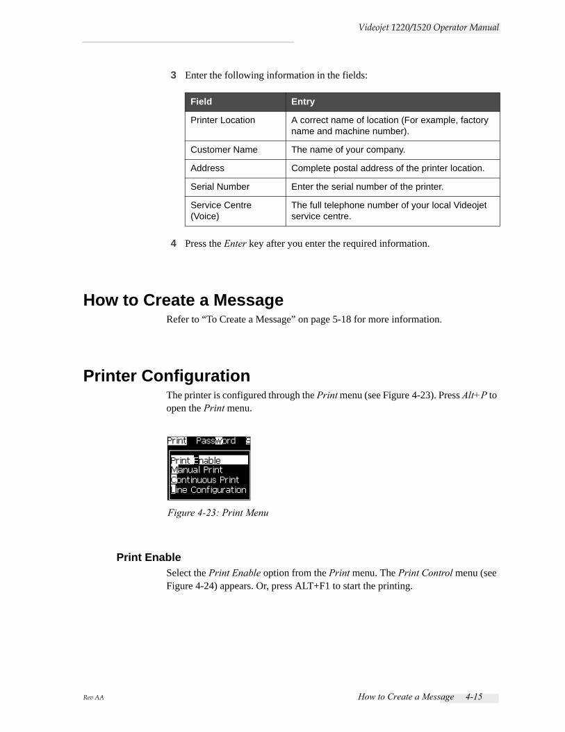
Printer ConfigurationThe printer is configured through the Print menu (see Figure 4-23). Press Alt+P to open the Print menu.
Print EnableSelect the Print Enable option from the Print menu. The Print Control menu (see Figure 4-24) appears. Or, press ALT+F1 to start the printing.
Field Entry
Printer Location A correct name of location (For example, factory name and machine number).
Customer Name The name of your company.
Address Complete postal address of the printer location.
Serial Number Enter the serial number of the printer.
Service Centre (Voice)
The full telephone number of your local Videojet service centre.
Figure 4-23: Print Menu
4-16 Printer Configuration Rev AA
Videojet 1220/1520 Operator Manual
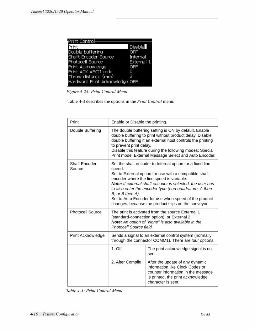
Table 4-3 describes the options in the Print Control menu.
Print Enable or Disable the printing.
Double Buffering The double buffering setting is ON by default. Enable double buffering to print without product delay. Disable double buffering if an external host controls the printing to prevent print delay.Disable this feature during the following modes: Special Print mode, External Message Select and Auto Encoder.
Shaft Encoder Source
Set the shaft encoder to Internal option for a fixed line speed. Set to External option for use with a compatible shaft encoder where the line speed is variable. Note: If external shaft encoder is selected, the user has to also enter the encoder type (non-quadrature, A then B, or B then A).Set to Auto Encoder for use when speed of the product changes, because the product slips on the conveyor.
Photocell Source The print is activated from the source External 1 (standard-connection option), or External 2.Note: An option of "None" is also available in the Photocell Source field.
Print Acknowledge Sends a signal to an external control system (normally through the connector COMM1). There are four options.
1. Off The print acknowledge signal is not sent.
2. After Compile After the update of any dynamic information like Clock Codes or counter information in the message is printed, the print acknowledge character is sent.
Table 4-3: Print Control Menu
Figure 4-24: Print Control Menu
Rev AA Printer Configuration 4-17
Videojet 1220/1520 Operator Manual
Manual Print OptionSelect Manual Print (see Figure 4-23 on page 4-15) from the Print menu if you do not require to start the printing from an external source. When you give the print command, the printer prints one copy of the message.
How to Use Continuous Print OptionIf you enable the Continuous Print (see Figure 4-23 on page 4-15) mode, the message is printed repeatedly. The message is printed if only the input of product detect is enabled. When you must print the messages at correct and regular intervals of time on continuous products, this option is useful.
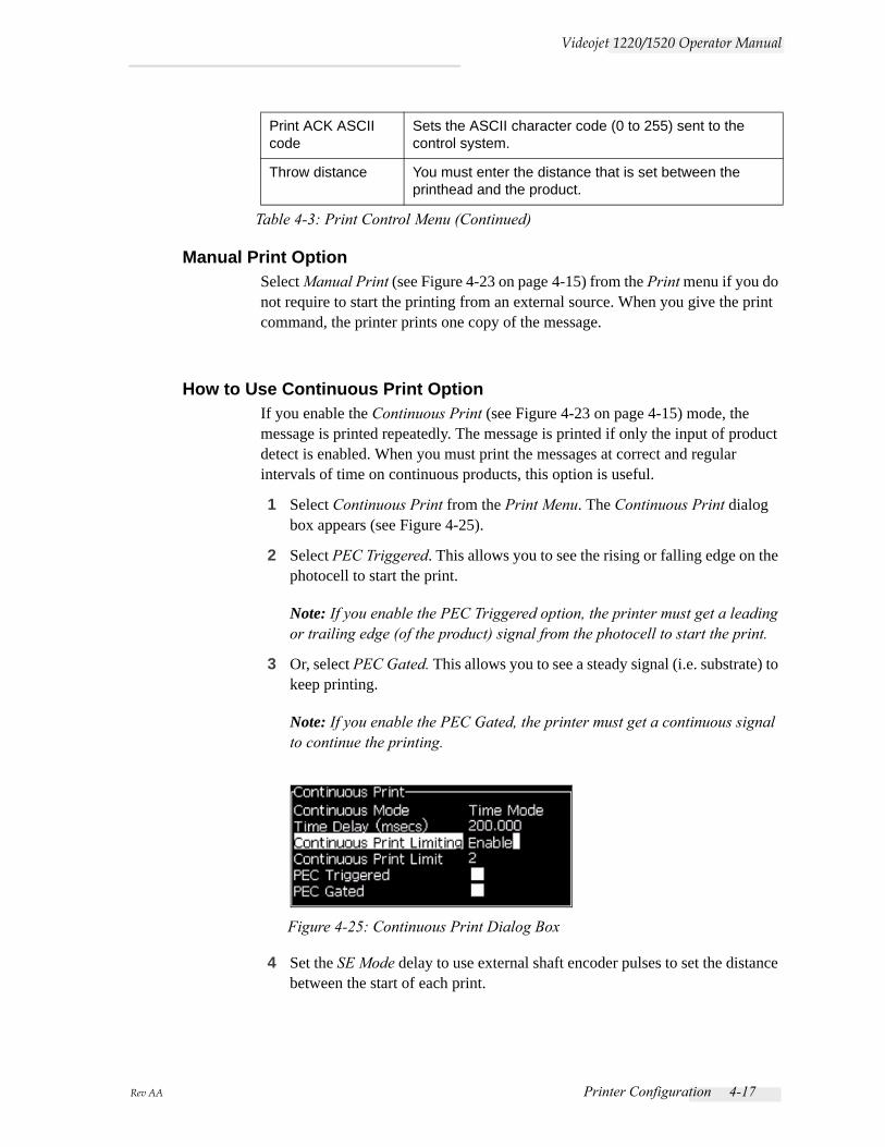
1 Select Continuous Print from the Print Menu. The Continuous Print dialog box appears (see Figure 4-25).
2 Select PEC Triggered. This allows you to see the rising or falling edge on the photocell to start the print.
Note: If you enable the PEC Triggered option, the printer must get a leading or trailing edge (of the product) signal from the photocell to start the print.
3 Or, select PEC Gated. This allows you to see a steady signal (i.e. substrate) to keep printing.
Note: If you enable the PEC Gated, the printer must get a continuous signal to continue the printing.
4 Set the SE Mode delay to use external shaft encoder pulses to set the distance between the start of each print.
Print ACK ASCII code
Sets the ASCII character code (0 to 255) sent to the control system.
Throw distance You must enter the distance that is set between the printhead and the product.
Table 4-3: Print Control Menu (Continued)
Figure 4-25: Continuous Print Dialog Box
4-18 How to Print Messages Rev AA
Videojet 1220/1520 Operator Manual
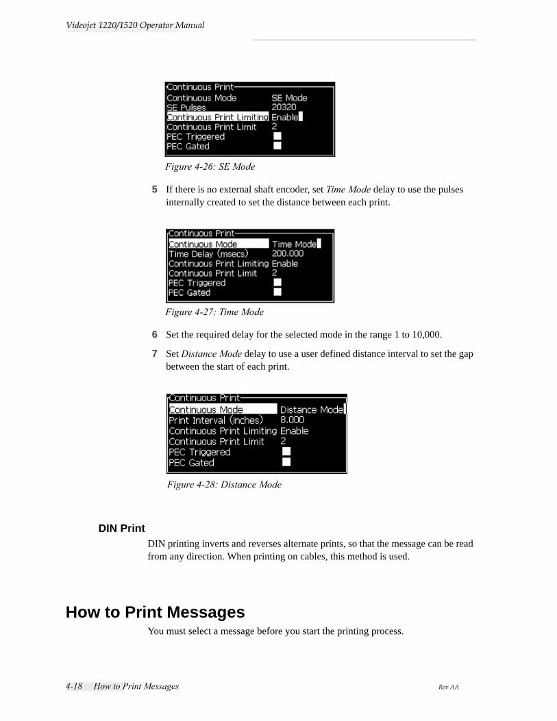
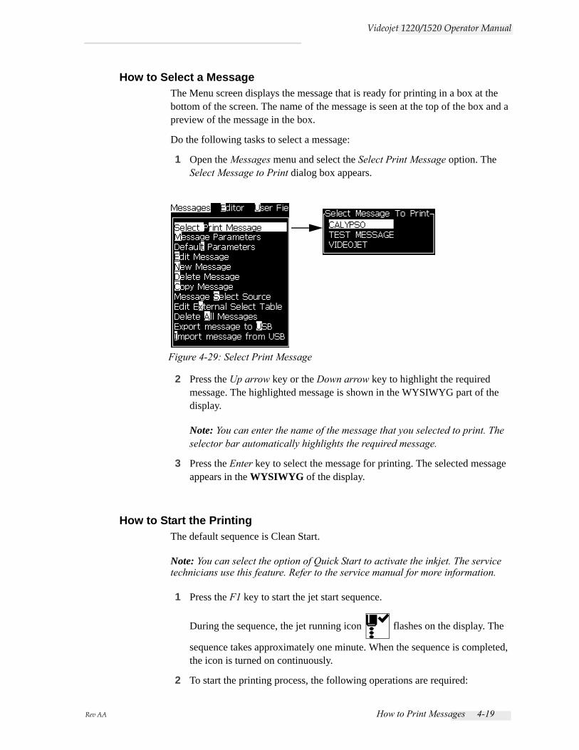
5 If there is no external shaft encoder, set Time Mode delay to use the pulses internally created to set the distance between each print.
6 Set the required delay for the selected mode in the range 1 to 10,000.
7 Set Distance Mode delay to use a user defined distance interval to set the gap between the start of each print.
DIN PrintDIN printing inverts and reverses alternate prints, so that the message can be read from any direction. When printing on cables, this method is used.
How to Print MessagesYou must select a message before you start the printing process.
Figure 4-26: SE Mode
Figure 4-27: Time Mode
Figure 4-28: Distance Mode
Rev AA How to Print Messages 4-19
Videojet 1220/1520 Operator Manual
How to Select a MessageThe Menu screen displays the message that is ready for printing in a box at the bottom of the screen. The name of the message is seen at the top of the box and a preview of the message in the box.
Do the following tasks to select a message:
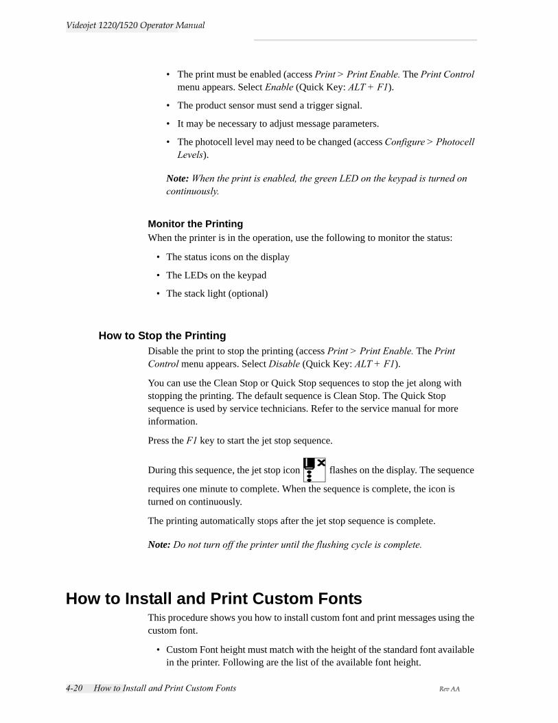
1 Open the Messages menu and select the Select Print Message option. The Select Message to Print dialog box appears.
2 Press the Up arrow key or the Down arrow key to highlight the required message. The highlighted message is shown in the WYSIWYG part of the display.
Note: You can enter the name of the message that you selected to print. The selector bar automatically highlights the required message.
3 Press the Enter key to select the message for printing. The selected message appears in the WYSIWYG of the display.
How to Start the PrintingThe default sequence is Clean Start.
Note: You can select the option of Quick Start to activate the inkjet. The service technicians use this feature. Refer to the service manual for more information.
1 Press the F1 key to start the jet start sequence.
During the sequence, the jet running icon flashes on the display. The
sequence takes approximately one minute. When the sequence is completed, the icon is turned on continuously.
2 To start the printing process, the following operations are required:
Figure 4-29: Select Print Message
4-20 How to Install and Print Custom Fonts Rev AA
Videojet 1220/1520 Operator Manual
• The print must be enabled (access Print > Print Enable. The Print Control menu appears. Select Enable (Quick Key: ALT + F1).
• The product sensor must send a trigger signal.
• It may be necessary to adjust message parameters.
• The photocell level may need to be changed (access Configure > Photocell Levels).
Note: When the print is enabled, the green LED on the keypad is turned on continuously.
Monitor the PrintingWhen the printer is in the operation, use the following to monitor the status:
• The status icons on the display
• The LEDs on the keypad
• The stack light (optional)
How to Stop the PrintingDisable the print to stop the printing (access Print > Print Enable. The Print Control menu appears. Select Disable (Quick Key: ALT + F1).
You can use the Clean Stop or Quick Stop sequences to stop the jet along with stopping the printing. The default sequence is Clean Stop. The Quick Stop sequence is used by service technicians. Refer to the service manual for more information.
Press the F1 key to start the jet stop sequence.
During this sequence, the jet stop icon flashes on the display. The sequence
requires one minute to complete. When the sequence is complete, the icon is turned on continuously.
The printing automatically stops after the jet stop sequence is complete.
Note: Do not turn off the printer until the flushing cycle is complete.
How to Install and Print Custom FontsThis procedure shows you how to install custom font and print messages using the custom font.
• Custom Font height must match with the height of the standard font available in the printer. Following are the list of the available font height.
Rev AA How to Install and Print Custom Fonts 4-21
Videojet 1220/1520 Operator Manual
- 5-high
- 7-high
- 9-high
- 12-high
- 16-high
- 24-high
- 34-high
• Custom font file must be in *.abf2 format.
• The naming convention of the font must be in xxhigh_custom.abf2. xx represents the height of the font. (Ex: A 16-high custom font file must be named as 16high_custom.abf2).
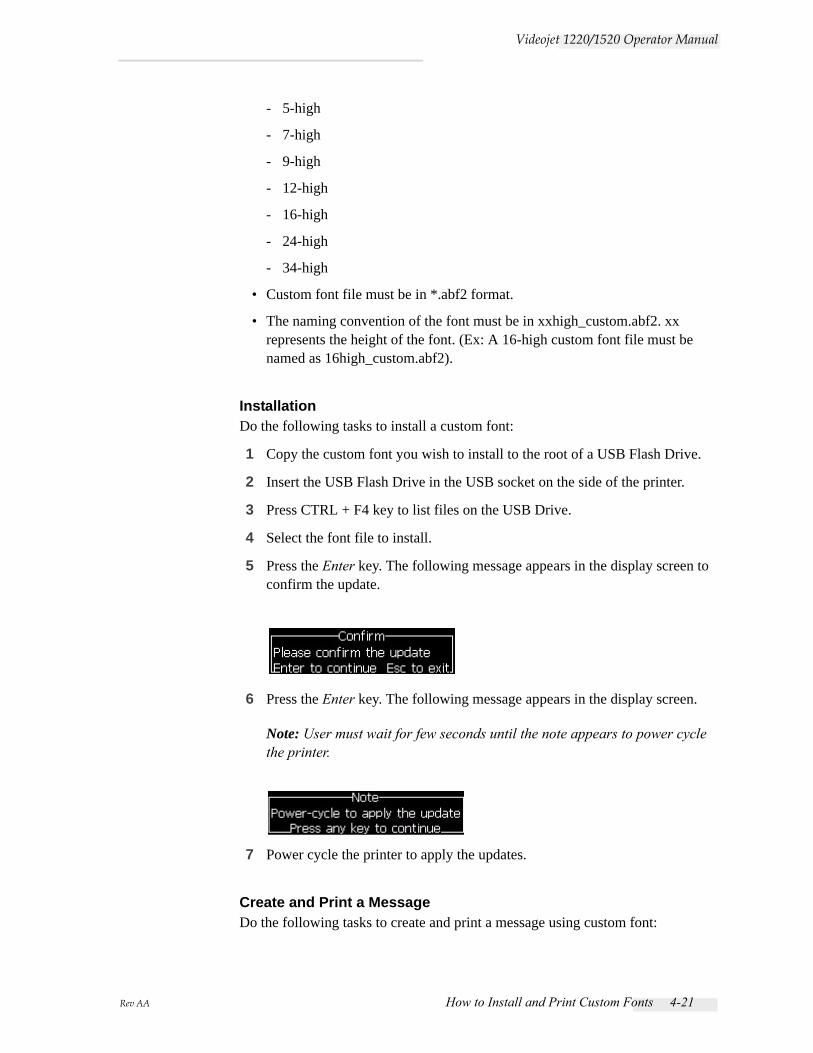
InstallationDo the following tasks to install a custom font:
1 Copy the custom font you wish to install to the root of a USB Flash Drive.
2 Insert the USB Flash Drive in the USB socket on the side of the printer.
3 Press CTRL + F4 key to list files on the USB Drive.
4 Select the font file to install.
5 Press the Enter key. The following message appears in the display screen to confirm the update.
6 Press the Enter key. The following message appears in the display screen.
Note: User must wait for few seconds until the note appears to power cycle the printer.
7 Power cycle the printer to apply the updates.
Create and Print a MessageDo the following tasks to create and print a message using custom font:
4-22 Turn off the Printer Rev AA
Videojet 1220/1520 Operator Manual
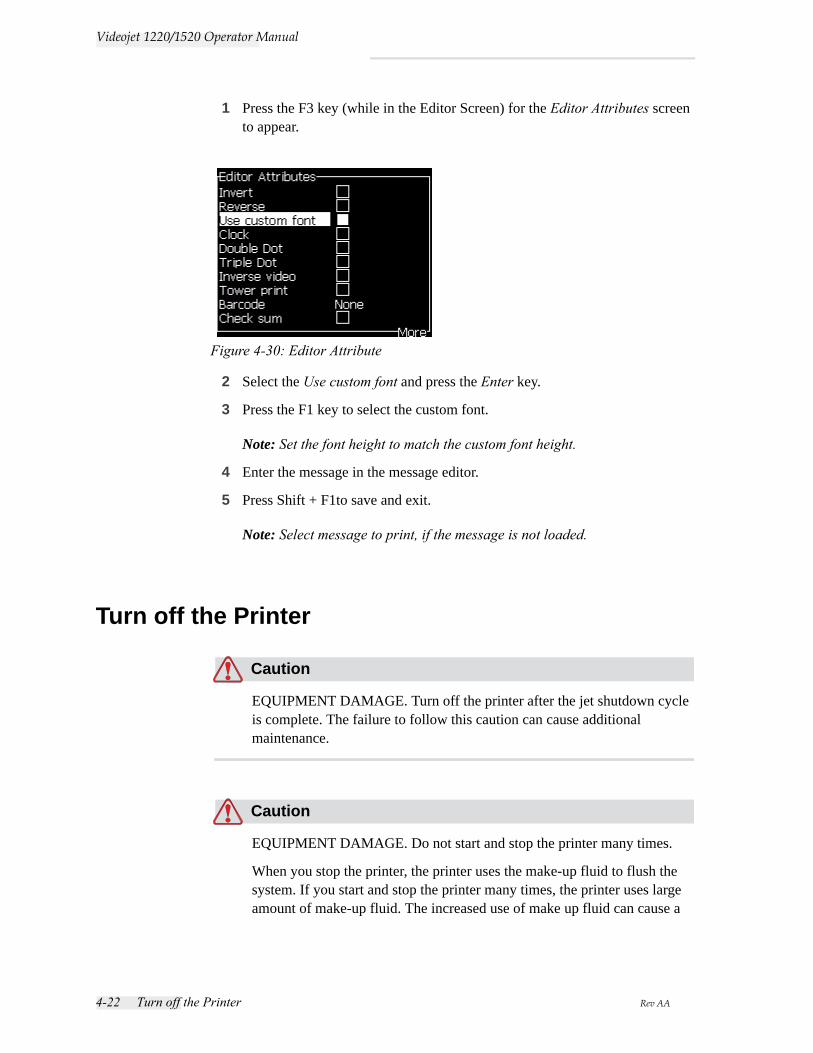
1 Press the F3 key (while in the Editor Screen) for the Editor Attributes screen to appear.
2 Select the Use custom font and press the Enter key.
3 Press the F1 key to select the custom font.
Note: Set the font height to match the custom font height.
4 Enter the message in the message editor.
5 Press Shift + F1to save and exit.
Note: Select message to print, if the message is not loaded.
Turn off the Printer
Caution
EQUIPMENT DAMAGE. Turn off the printer after the jet shutdown cycle is complete. The failure to follow this caution can cause additional maintenance.
Caution
EQUIPMENT DAMAGE. Do not start and stop the printer many times.
When you stop the printer, the printer uses the make-up fluid to flush the system. If you start and stop the printer many times, the printer uses large amount of make-up fluid. The increased use of make up fluid can cause a
Figure 4-30: Editor Attribute

Rev AA Turn off the Printer 4-23
Videojet 1220/1520 Operator Manual
Ink Core Level High error and low ink viscosity. To prevent this problem, quick start and stop must be used.
Press the main power switch to turn off the printer.
Note: It is recommended to start the printer once in every 10 days. If the printer is shutdown for more than 10 days, it is recommended to follow the extended shutdown routine. Refer to “How to Prepare for Long-term Shutdown (Storage) or Transportation” on page 6-2 for the procedure.
Rev AA Introduction 5-1
5User Interface
IntroductionThis chapter describes how you can use the user interface (UI) to do the following tasks:
• Create messages
• Edit messages
• Save messages
• Create user fields
The UI contains the following screen:
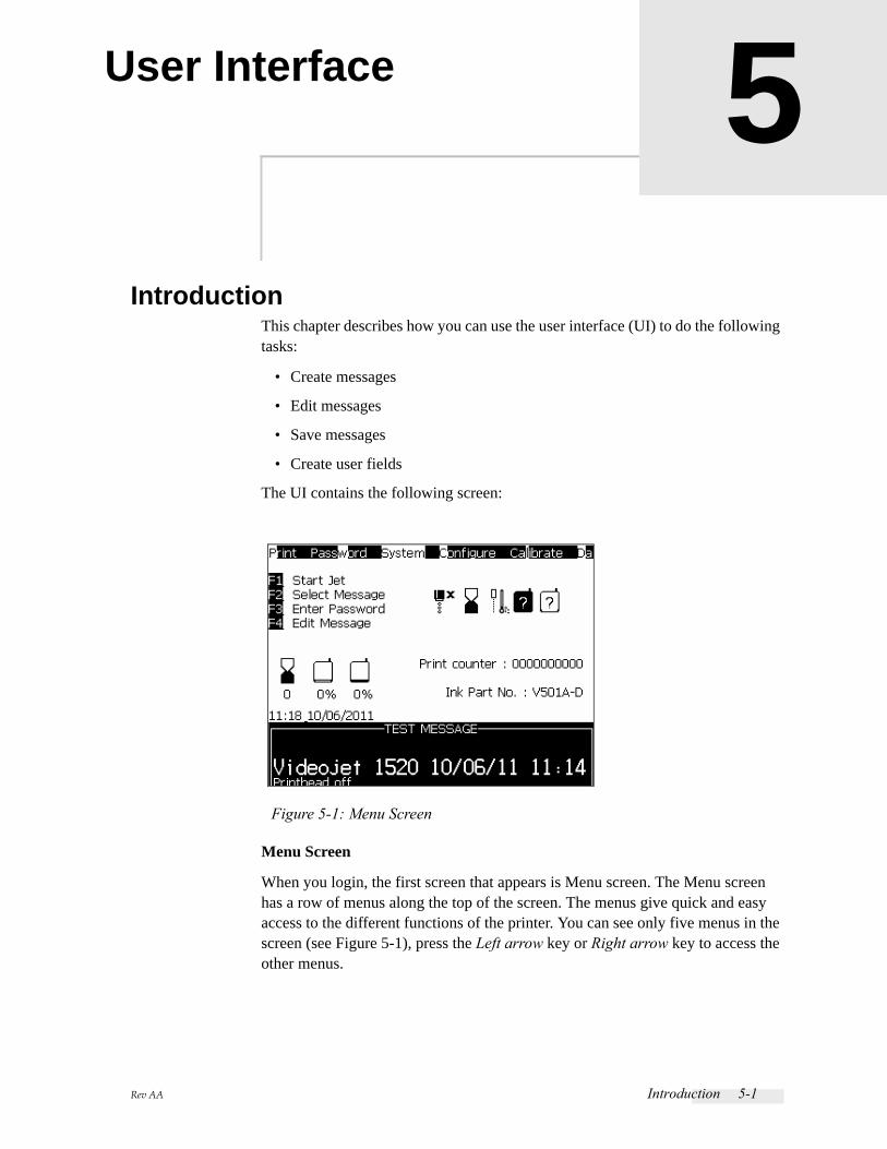
Menu Screen
When you login, the first screen that appears is Menu screen. The Menu screen has a row of menus along the top of the screen. The menus give quick and easy access to the different functions of the printer. You can see only five menus in the screen (see Figure 5-1), press the Left arrow key or Right arrow key to access the other menus.
Figure 5-1: Menu Screen
5-2 Introduction Rev AA
Videojet 1220/1520 Operator Manual
To Select the Menus and ItemsTo select the menus, and the items in the menus, you can use either the arrow keys or the short cut keys.
Arrow Keys
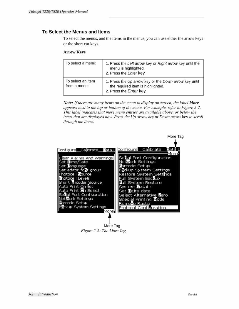
Note: If there are many items on the menu to display on screen, the label More appears next to the top or bottom of the menu. For example, refer to Figure 5-2. This label indicates that more menu entries are available above, or below the items that are displayed now. Press the Up arrow key or Down arrow key to scroll through the items.
To select a menu: 1. Press the Left arrow key or Right arrow key until the menu is highlighted.
2. Press the Enter key.
To select an item from a menu:
1. Press the Up arrow key or the Down arrow key until the required item is highlighted.
2. Press the Enter key.
Figure 5-2: The More TagMore Tag
More Tag
Rev AA Introduction 5-3
Videojet 1220/1520 Operator Manual
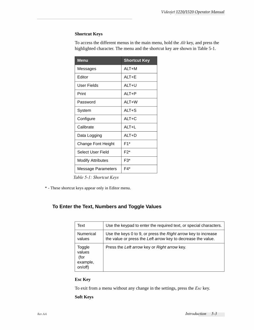
Shortcut Keys
To access the different menus in the main menu, hold the Alt key, and press the highlighted character. The menu and the shortcut key are shown in Table 5-1.
* - These shortcut keys appear only in Editor menu.
To Enter the Text, Numbers and Toggle Values
Esc Key
To exit from a menu without any change in the settings, press the Esc key.
Soft Keys
Menu Shortcut Key
Messages ALT+M
Editor ALT+E
User Fields ALT+U
Print ALT+P
Password ALT+W
System ALT+S
Configure ALT+C
Calibrate ALT+L
Data Logging ALT+D
Change Font Height F1*
Select User Field F2*
Modify Attributes F3*
Message Parameters F4*
Table 5-1: Shortcut Keys
Text Use the keypad to enter the required text, or special characters.
Numerical values
Use the keys 0 to 9, or press the Right arrow key to increase the value or press the Left arrow key to decrease the value.
Toggle values (for example, on/off)
Press the Left arrow key or Right arrow key.
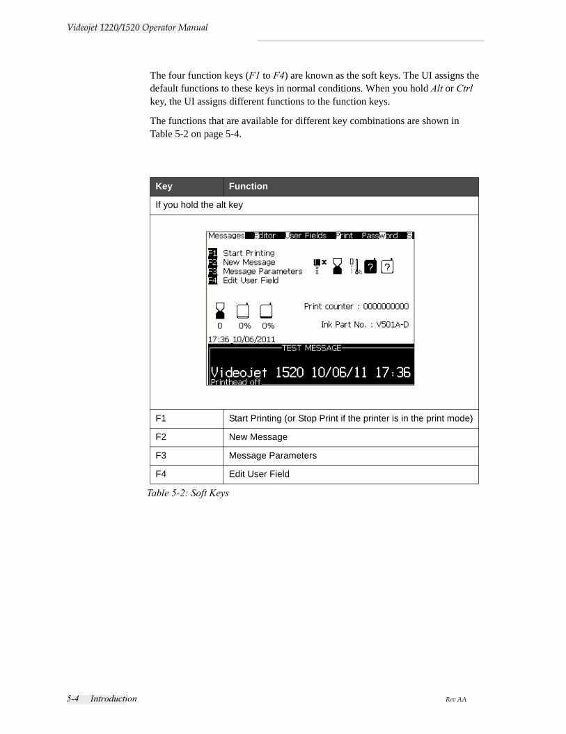
5-4 Introduction Rev AA
Videojet 1220/1520 Operator Manual
The four function keys (F1 to F4) are known as the soft keys. The UI assigns the default functions to these keys in normal conditions. When you hold Alt or Ctrl key, the UI assigns different functions to the function keys.
The functions that are available for different key combinations are shown in Table 5-2 on page 5-4.
Key Function
If you hold the alt key
F1 Start Printing (or Stop Print if the printer is in the print mode)
F2 New Message
F3 Message Parameters
F4 Edit User Field
Table 5-2: Soft Keys
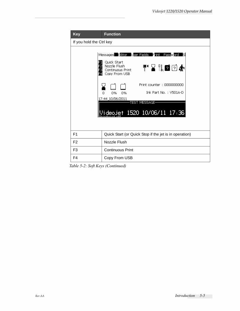
Rev AA Introduction 5-5
Videojet 1220/1520 Operator Manual
If you hold the Ctrl key
F1 Quick Start (or Quick Stop if the jet is in operation)
F2 Nozzle Flush
F3 Continuous Print
F4 Copy From USB
Key Function
Table 5-2: Soft Keys (Continued)

5-6 Menu Description Rev AA
Videojet 1220/1520 Operator Manual
Menu Description
Messages
Messages Menu Commands Function
Select Print Message
Opens the Select Message To Print dialog box. Select a message to print or edit.
Message Parameters
Opens the message parameters for the selected message. All parameters can be changed.
Default parameters Opens the Default Parameters menu. All the default parameters for new messages can be changed.
Edit Message Opens the Select Message to Edit dialog box. The selected message is opened in an edit screen. To save the edited message, go to the Editor menu
New Message Opens the New Message dialog box. The system prompts to enter the new message name. The user can enter the new message in the edit screen. To save the new message, go to the Editor menu. The parameters for a new message are set to the default values.
Delete Message Opens the Select Message to Delete dialog box. The selected message is deleted.Note: You cannot delete the Test Message and the message selected for printing (shown in the WYSIWYG).
Copy Message Opens the Copy Message dialog box. Enter message names in the From and To fields.If a message exists, and you try to copy the content into that message, the following message appears on the display:“Already exists. Overwrite it?”(answer with Y or N).
Message Select Source* (standard for Videojet 1520 if PCB3 is fitted and not available in Videojet 1220)
Opens the Message Select Source dialog box, with options Internal or External.
Table 5-3: Messages Menu and Commands
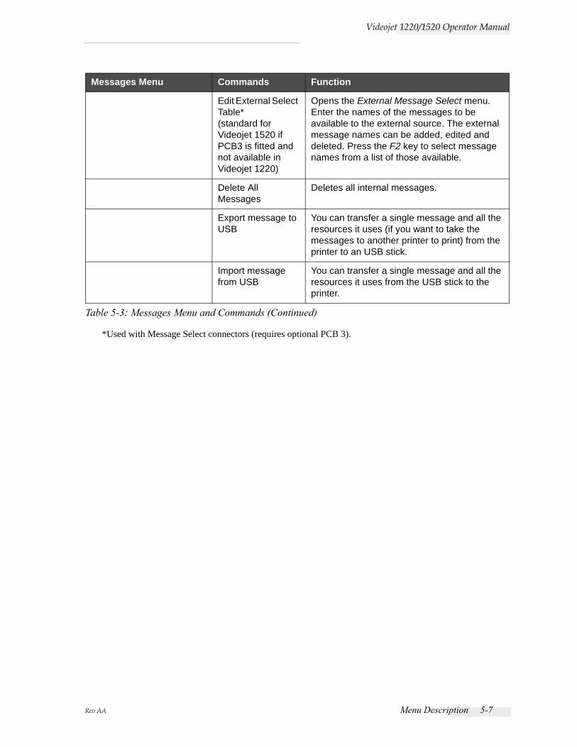
Rev AA Menu Description 5-7
Videojet 1220/1520 Operator Manual
*Used with Message Select connectors (requires optional PCB 3).
Edit External Select Table* (standard for Videojet 1520 if PCB3 is fitted and not available in Videojet 1220)
Opens the External Message Select menu. Enter the names of the messages to be available to the external source. The external message names can be added, edited and deleted. Press the F2 key to select message names from a list of those available.
Delete All Messages
Deletes all internal messages.
Export message to USB
You can transfer a single message and all the resources it uses (if you want to take the messages to another printer to print) from the printer to an USB stick.
Import message from USB
You can transfer a single message and all the resources it uses from the USB stick to the printer.
Messages Menu Commands Function
Table 5-3: Messages Menu and Commands (Continued)
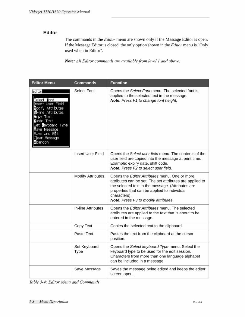
5-8 Menu Description Rev AA
Videojet 1220/1520 Operator Manual
Editor The commands in the Editor menu are shown only if the Message Editor is open. If the Message Editor is closed, the only option shown in the Editor menu is "Only used when in Editor".
Note: All Editor commands are available from level 1 and above.
Editor Menu Commands Function
Select Font Opens the Select Font menu. The selected font is applied to the selected text in the message.Note: Press F1 to change font height.
Insert User Field Opens the Select user field menu. The contents of the user field are copied into the message at print time.Example: expiry date, shift code.Note: Press F2 to select user field.
Modify Attributes Opens the Editor Attributes menu. One or more attributes can be set. The set attributes are applied to the selected text in the message. (Attributes are properties that can be applied to individual characters).Note: Press F3 to modify attributes.
In-line Attributes Opens the Editor Attributes menu. The selected attributes are applied to the text that is about to be entered in the message.
Copy Text Copies the selected text to the clipboard.
Paste Text Pastes the text from the clipboard at the cursor position.
Set Keyboard Type
Opens the Select keyboard Type menu. Select the keyboard type to be used for the edit session. Characters from more than one language alphabet can be included in a message.
Save Message Saves the message being edited and keeps the editor screen open.
Table 5-4: Editor Menu and Commands
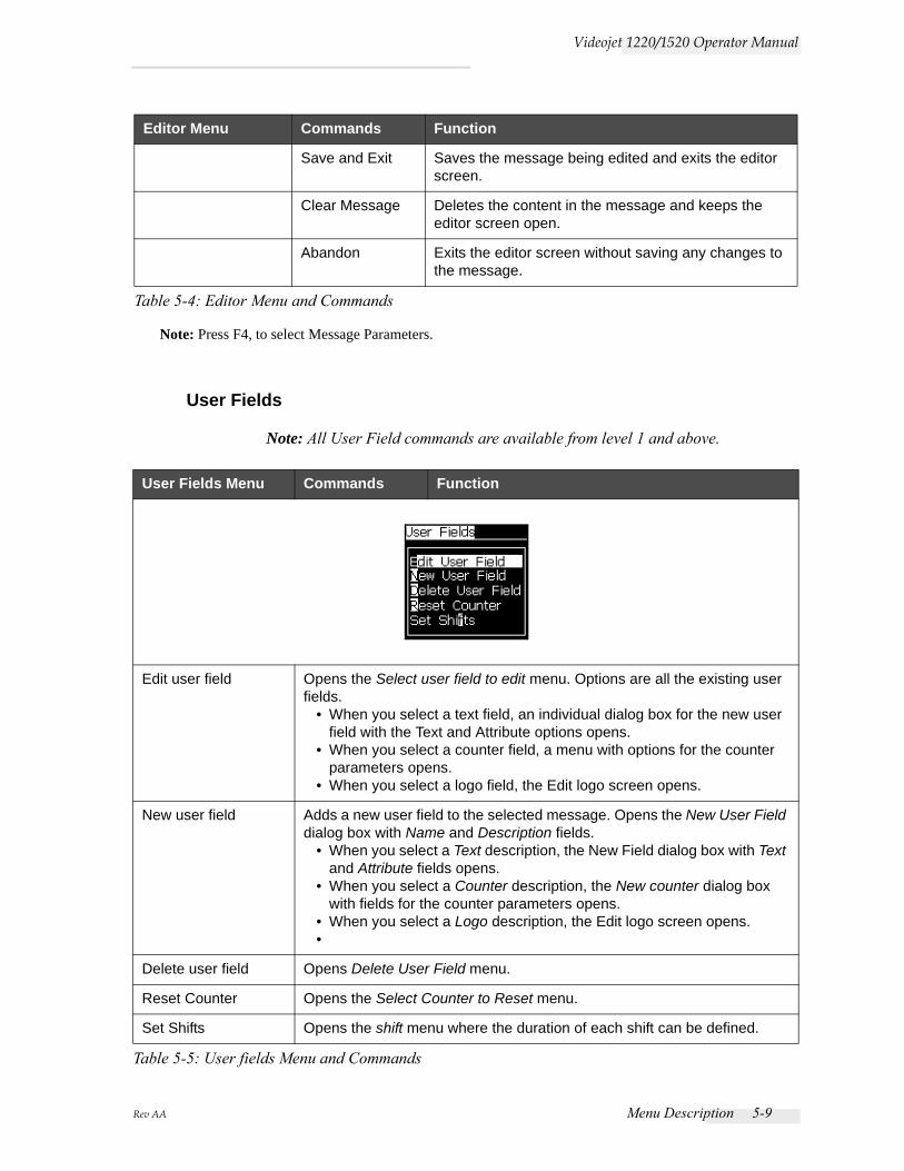
Rev AA Menu Description 5-9
Videojet 1220/1520 Operator Manual
Note: Press F4, to select Message Parameters.
User Fields
Note: All User Field commands are available from level 1 and above.
Save and Exit Saves the message being edited and exits the editor screen.
Clear Message Deletes the content in the message and keeps the editor screen open.
Abandon Exits the editor screen without saving any changes to the message.
User Fields Menu Commands Function
Edit user field Opens the Select user field to edit menu. Options are all the existing user fields.
• When you select a text field, an individual dialog box for the new user field with the Text and Attribute options opens.
• When you select a counter field, a menu with options for the counter parameters opens.
• When you select a logo field, the Edit logo screen opens.
New user field Adds a new user field to the selected message. Opens the New User Field dialog box with Name and Description fields.
• When you select a Text description, the New Field dialog box with Text and Attribute fields opens.
• When you select a Counter description, the New counter dialog box with fields for the counter parameters opens.
• When you select a Logo description, the Edit logo screen opens.•
Delete user field Opens Delete User Field menu.
Reset Counter Opens the Select Counter to Reset menu.
Set Shifts Opens the shift menu where the duration of each shift can be defined.
Table 5-5: User fields Menu and Commands
Editor Menu Commands Function
Table 5-4: Editor Menu and Commands
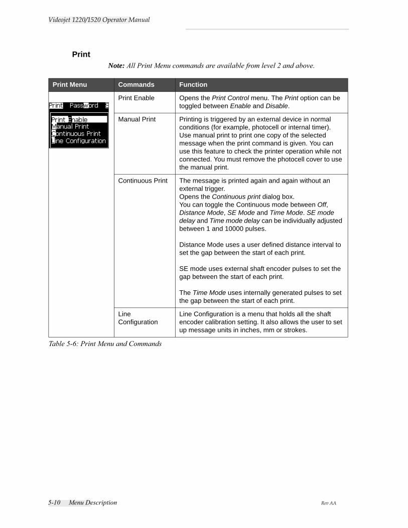
5-10 Menu Description Rev AA
Videojet 1220/1520 Operator Manual
Print Note: All Print Menu commands are available from level 2 and above.
Print Menu Commands Function
Print Enable Opens the Print Control menu. The Print option can be toggled between Enable and Disable.
Manual Print Printing is triggered by an external device in normal conditions (for example, photocell or internal timer).Use manual print to print one copy of the selected message when the print command is given. You can use this feature to check the printer operation while not connected. You must remove the photocell cover to use the manual print.
Continuous Print The message is printed again and again without an external trigger. Opens the Continuous print dialog box. You can toggle the Continuous mode between Off, Distance Mode, SE Mode and Time Mode. SE mode delay and Time mode delay can be individually adjusted between 1 and 10000 pulses.
Distance Mode uses a user defined distance interval to set the gap between the start of each print.
SE mode uses external shaft encoder pulses to set the gap between the start of each print.
The Time Mode uses internally generated pulses to set the gap between the start of each print.
Line Configuration
Line Configuration is a menu that holds all the shaft encoder calibration setting. It also allows the user to set up message units in inches, mm or strokes.
Table 5-6: Print Menu and Commands
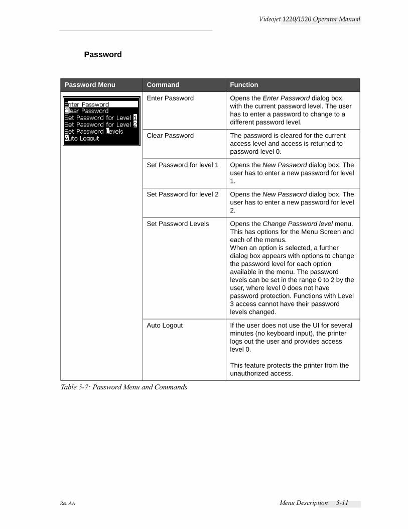
Rev AA Menu Description 5-11
Videojet 1220/1520 Operator Manual
Password
Password Menu Command Function
Enter Password Opens the Enter Password dialog box, with the current password level. The user has to enter a password to change to a different password level.
Clear Password The password is cleared for the current access level and access is returned to password level 0.
Set Password for level 1 Opens the New Password dialog box. The user has to enter a new password for level 1.
Set Password for level 2 Opens the New Password dialog box. The user has to enter a new password for level 2.
Set Password Levels Opens the Change Password level menu. This has options for the Menu Screen and each of the menus.When an option is selected, a further dialog box appears with options to change the password level for each option available in the menu. The password levels can be set in the range 0 to 2 by the user, where level 0 does not have password protection. Functions with Level 3 access cannot have their password levels changed.
Auto Logout If the user does not use the UI for several minutes (no keyboard input), the printer logs out the user and provides access level 0.
This feature protects the printer from the unauthorized access.
Table 5-7: Password Menu and Commands
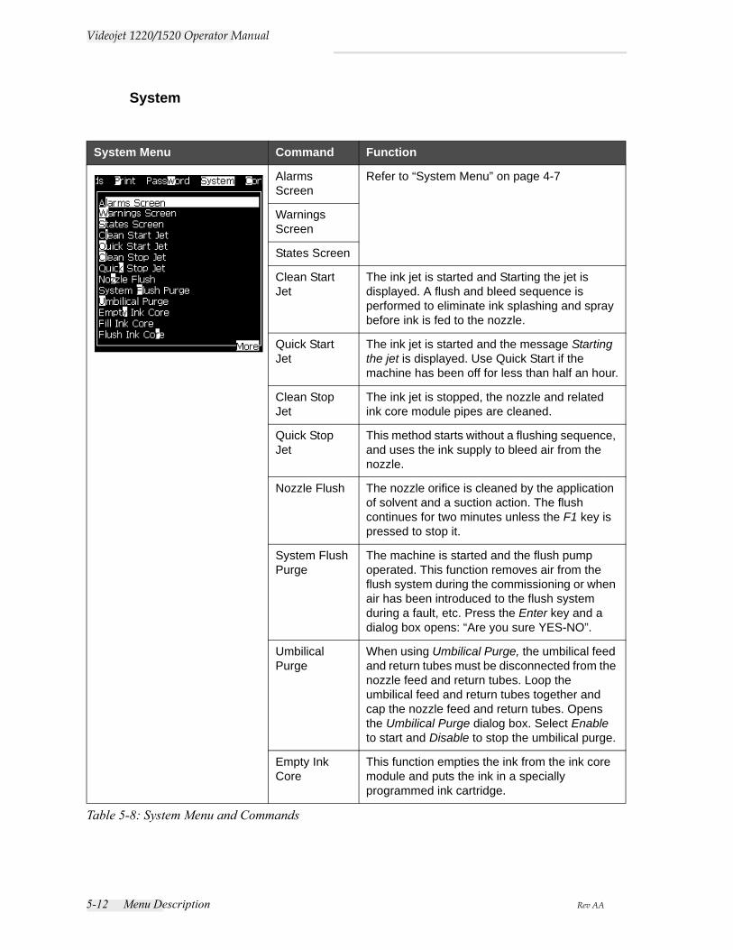
5-12 Menu Description Rev AA
Videojet 1220/1520 Operator Manual
System
System Menu Command Function
Alarms Screen
Refer to “System Menu” on page 4-7
Warnings Screen
States Screen
Clean Start Jet
The ink jet is started and Starting the jet is displayed. A flush and bleed sequence is performed to eliminate ink splashing and spray before ink is fed to the nozzle.
Quick Start Jet
The ink jet is started and the message Starting the jet is displayed. Use Quick Start if the machine has been off for less than half an hour.
Clean Stop Jet
The ink jet is stopped, the nozzle and related ink core module pipes are cleaned.
Quick Stop Jet
This method starts without a flushing sequence, and uses the ink supply to bleed air from the nozzle.
Nozzle Flush The nozzle orifice is cleaned by the application of solvent and a suction action. The flush continues for two minutes unless the F1 key is pressed to stop it.
System Flush Purge
The machine is started and the flush pump operated. This function removes air from the flush system during the commissioning or when air has been introduced to the flush system during a fault, etc. Press the Enter key and a dialog box opens: “Are you sure YES-NO”.
Umbilical Purge
When using Umbilical Purge, the umbilical feed and return tubes must be disconnected from the nozzle feed and return tubes. Loop the umbilical feed and return tubes together and cap the nozzle feed and return tubes. Opens the Umbilical Purge dialog box. Select Enable to start and Disable to stop the umbilical purge.
Empty Ink Core
This function empties the ink from the ink core module and puts the ink in a specially programmed ink cartridge.
Table 5-8: System Menu and Commands
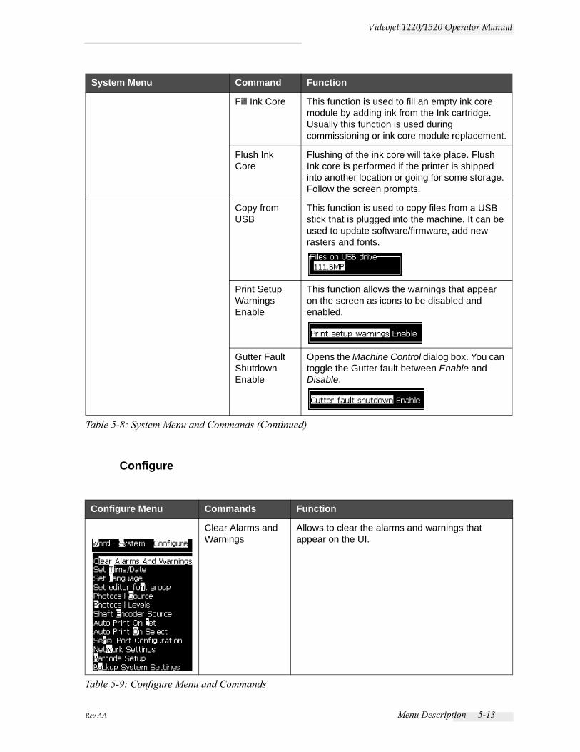
Rev AA Menu Description 5-13
Videojet 1220/1520 Operator Manual
Configure
Fill Ink Core This function is used to fill an empty ink core module by adding ink from the Ink cartridge. Usually this function is used during commissioning or ink core module replacement.
Flush Ink Core
Flushing of the ink core will take place. Flush Ink core is performed if the printer is shipped into another location or going for some storage. Follow the screen prompts.
Copy from USB
This function is used to copy files from a USB stick that is plugged into the machine. It can be used to update software/firmware, add new rasters and fonts.
Print Setup Warnings Enable
This function allows the warnings that appear on the screen as icons to be disabled and enabled.
Gutter Fault Shutdown Enable
Opens the Machine Control dialog box. You can toggle the Gutter fault between Enable and Disable.
Configure Menu Commands Function
Clear Alarms and Warnings
Allows to clear the alarms and warnings that appear on the UI.
Table 5-9: Configure Menu and Commands
System Menu Command Function
Table 5-8: System Menu and Commands (Continued)
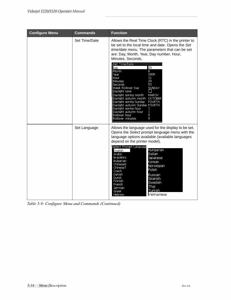
5-14 Menu Description Rev AA
Videojet 1220/1520 Operator Manual
Set Time/Date Allows the Real Time Clock (RTC) in the printer to be set to the local time and date. Opens the Set time/date menu. The parameters that can be set are: Day, Month, Year, Day number, Hour, Minutes, Seconds.
Set Language Allows the language used for the display to be set. Opens the Select prompt language menu with the language options available (available languages depend on the printer model).
Configure Menu Commands Function
Table 5-9: Configure Menu and Commands (Continued)
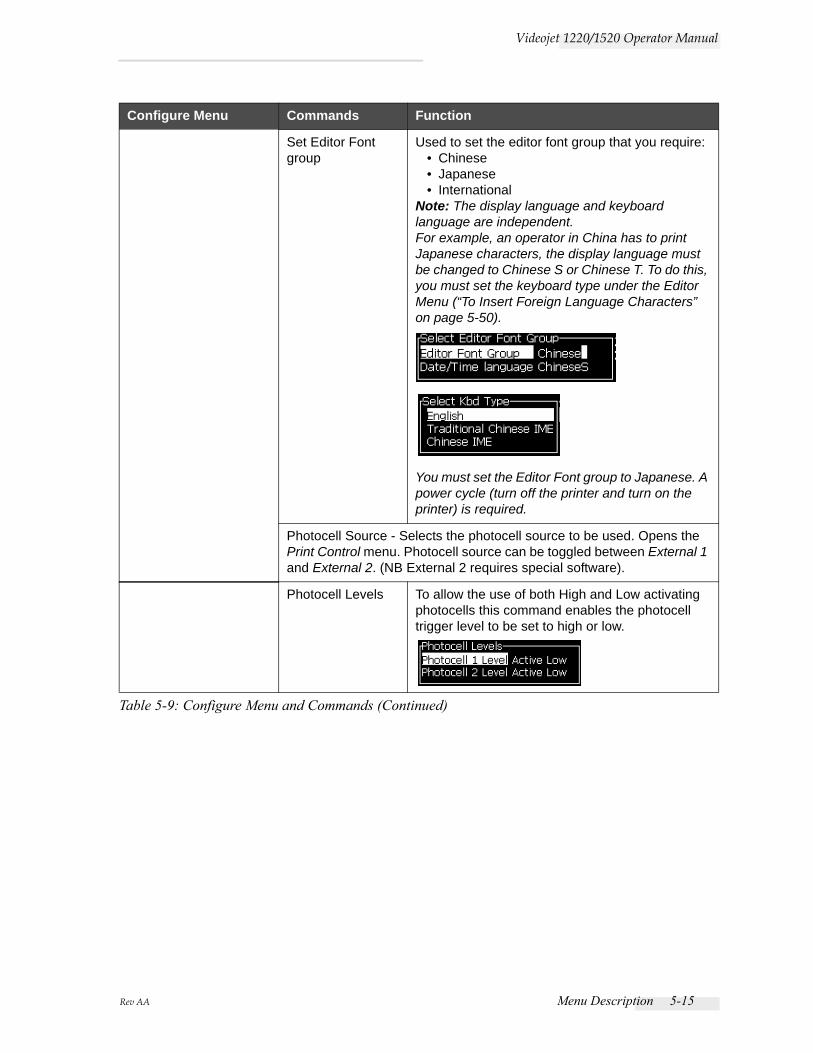
Rev AA Menu Description 5-15
Videojet 1220/1520 Operator Manual
Set Editor Font group
Used to set the editor font group that you require: • Chinese• Japanese• International
Note: The display language and keyboard language are independent.For example, an operator in China has to print Japanese characters, the display language must be changed to Chinese S or Chinese T. To do this, you must set the keyboard type under the Editor Menu (“To Insert Foreign Language Characters” on page 5-50).
You must set the Editor Font group to Japanese. A power cycle (turn off the printer and turn on the printer) is required.
Photocell Source - Selects the photocell source to be used. Opens the Print Control menu. Photocell source can be toggled between External 1 and External 2. (NB External 2 requires special software).
Photocell Levels To allow the use of both High and Low activating photocells this command enables the photocell trigger level to be set to high or low.
Configure Menu Commands Function
Table 5-9: Configure Menu and Commands (Continued)
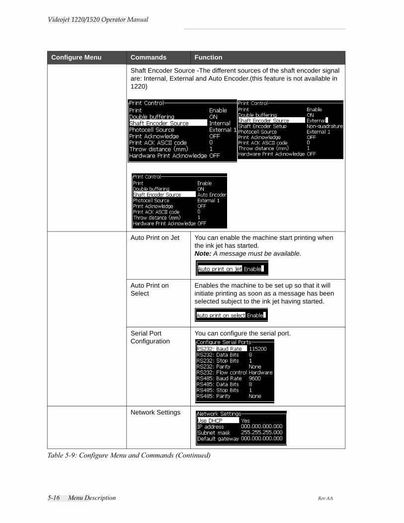
5-16 Menu Description Rev AA
Videojet 1220/1520 Operator Manual
Shaft Encoder Source -The different sources of the shaft encoder signal are: Internal, External and Auto Encoder.(this feature is not available in 1220)
Auto Print on Jet You can enable the machine start printing when the ink jet has started.Note: A message must be available.
Auto Print on Select
Enables the machine to be set up so that it will initiate printing as soon as a message has been selected subject to the ink jet having started.
Serial Port Configuration
You can configure the serial port.
Network Settings
Configure Menu Commands Function
Table 5-9: Configure Menu and Commands (Continued)
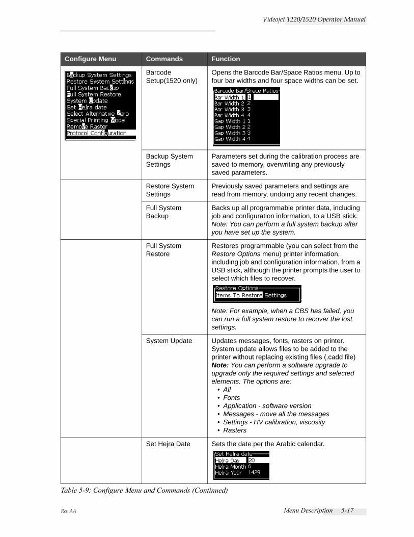
Rev AA Menu Description 5-17
Videojet 1220/1520 Operator Manual
Barcode Setup(1520 only)
Opens the Barcode Bar/Space Ratios menu. Up to four bar widths and four space widths can be set.
Backup System Settings
Parameters set during the calibration process are saved to memory, overwriting any previously saved parameters.
Restore System Settings
Previously saved parameters and settings are read from memory, undoing any recent changes.
Full System Backup
Backs up all programmable printer data, including job and configuration information, to a USB stick.Note: You can perform a full system backup after you have set up the system.
Full System Restore
Restores programmable (you can select from the Restore Options menu) printer information, including job and configuration information, from a USB stick, although the printer prompts the user to select which files to recover.
Note: For example, when a CBS has failed, you can run a full system restore to recover the lost settings.
System Update Updates messages, fonts, rasters on printer. System update allows files to be added to the printer without replacing existing files (.cadd file)Note: You can perform a software upgrade to upgrade only the required settings and selected elements. The options are:
• All• Fonts• Application - software version• Messages - move all the messages• Settings - HV calibration, viscosity• Rasters
Set Hejra Date Sets the date per the Arabic calendar.
Configure Menu Commands Function
Table 5-9: Configure Menu and Commands (Continued)
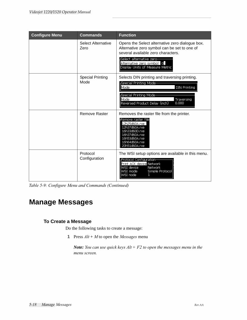
5-18 Manage Messages Rev AA
Videojet 1220/1520 Operator Manual
Manage Messages
To Create a MessageDo the following tasks to create a message:
1 Press Alt + M to open the Messages menu
Note: You can use quick keys Alt + F2 to open the messages menu in the menu screen.
Select Alternative Zero
Opens the Select alternative zero dialogue box. Alternative zero symbol can be set to one of several available zero characters.
Special Printing Mode
Selects DIN printing and traversing printing.
Remove Raster Removes the raster file from the printer.
Protocol Configuration
The WSI setup options are available in this menu.
Configure Menu Commands Function
Table 5-9: Configure Menu and Commands (Continued)
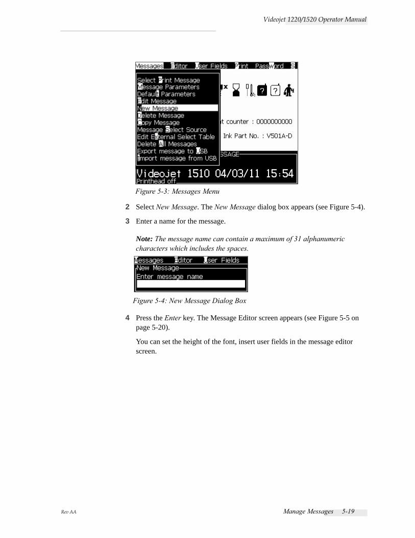
Rev AA Manage Messages 5-19
Videojet 1220/1520 Operator Manual
2 Select New Message. The New Message dialog box appears (see Figure 5-4).
3 Enter a name for the message.
Note: The message name can contain a maximum of 31 alphanumeric characters which includes the spaces.
4 Press the Enter key. The Message Editor screen appears (see Figure 5-5 on page 5-20).
You can set the height of the font, insert user fields in the message editor screen.
Figure 5-3: Messages Menu
Figure 5-4: New Message Dialog Box
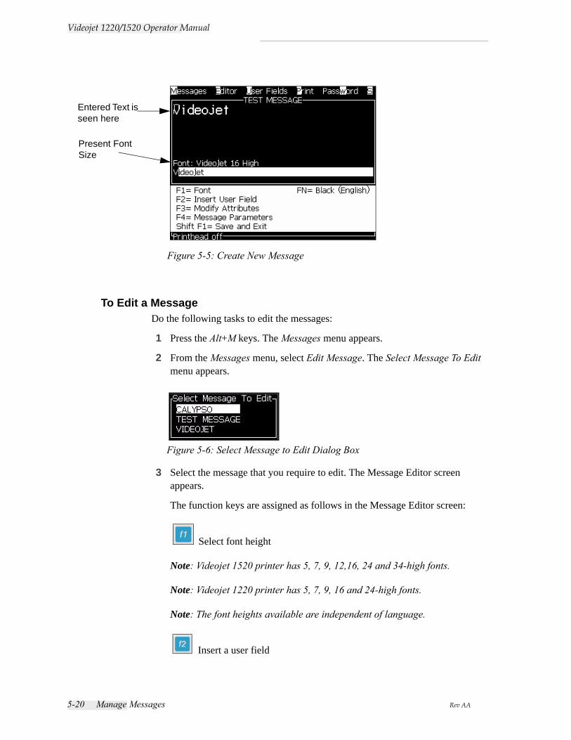
5-20 Manage Messages Rev AA
Videojet 1220/1520 Operator Manual
To Edit a MessageDo the following tasks to edit the messages:
1 Press the Alt+M keys. The Messages menu appears.
2 From the Messages menu, select Edit Message. The Select Message To Edit menu appears.
3 Select the message that you require to edit. The Message Editor screen appears.
The function keys are assigned as follows in the Message Editor screen:
Select font height
Note: Videojet 1520 printer has 5, 7, 9, 12,16, 24 and 34-high fonts.
Note: Videojet 1220 printer has 5, 7, 9, 16 and 24-high fonts.
Note: The font heights available are independent of language.
Insert a user field
Figure 5-5: Create New Message
Entered Text is seen here
Present Font Size
Figure 5-6: Select Message to Edit Dialog Box
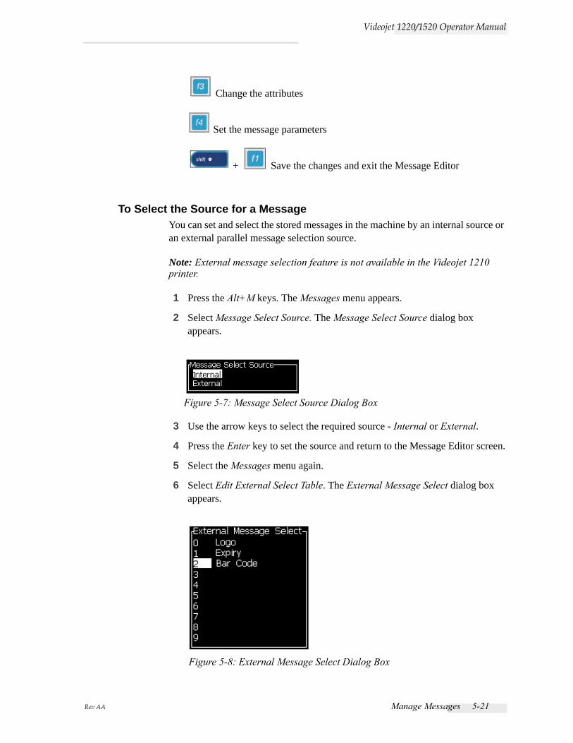
Rev AA Manage Messages 5-21
Videojet 1220/1520 Operator Manual
Change the attributes
Set the message parameters
+ Save the changes and exit the Message Editor
To Select the Source for a MessageYou can set and select the stored messages in the machine by an internal source or an external parallel message selection source.
Note: External message selection feature is not available in the Videojet 1210 printer.
1 Press the Alt+M keys. The Messages menu appears.
2 Select Message Select Source. The Message Select Source dialog box appears.
3 Use the arrow keys to select the required source - Internal or External.
4 Press the Enter key to set the source and return to the Message Editor screen.
5 Select the Messages menu again.
6 Select Edit External Select Table. The External Message Select dialog box appears.
Figure 5-7: Message Select Source Dialog Box
Figure 5-8: External Message Select Dialog Box
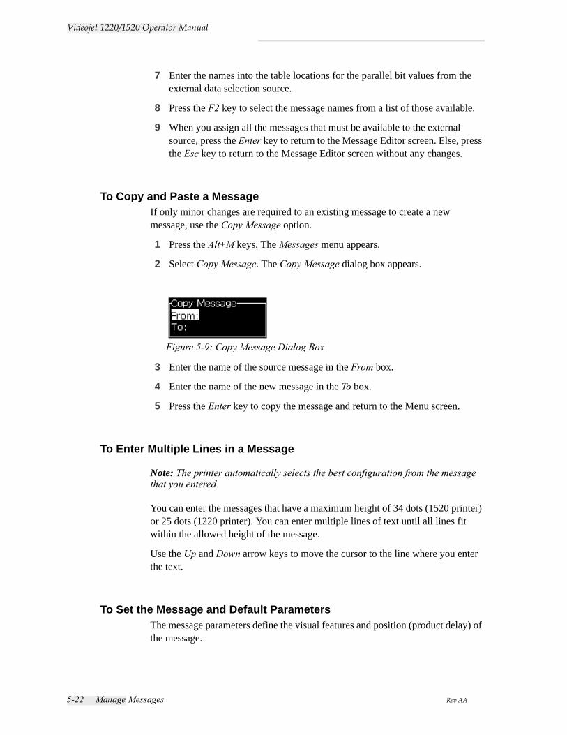
5-22 Manage Messages Rev AA
Videojet 1220/1520 Operator Manual
7 Enter the names into the table locations for the parallel bit values from the external data selection source.
8 Press the F2 key to select the message names from a list of those available.
9 When you assign all the messages that must be available to the external source, press the Enter key to return to the Message Editor screen. Else, press the Esc key to return to the Message Editor screen without any changes.
To Copy and Paste a MessageIf only minor changes are required to an existing message to create a new message, use the Copy Message option.
1 Press the Alt+M keys. The Messages menu appears.
2 Select Copy Message. The Copy Message dialog box appears.
3 Enter the name of the source message in the From box.
4 Enter the name of the new message in the To box.
5 Press the Enter key to copy the message and return to the Menu screen.
To Enter Multiple Lines in a Message
Note: The printer automatically selects the best configuration from the message that you entered.
You can enter the messages that have a maximum height of 34 dots (1520 printer) or 25 dots (1220 printer). You can enter multiple lines of text until all lines fit within the allowed height of the message.
Use the Up and Down arrow keys to move the cursor to the line where you enter the text.
To Set the Message and Default ParametersThe message parameters define the visual features and position (product delay) of the message.
Figure 5-9: Copy Message Dialog Box
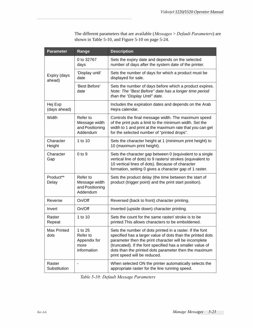
Rev AA Manage Messages 5-23
Videojet 1220/1520 Operator Manual
The different parameters that are available (Messages > Default Parameters) are shown in Table 5-10, and Figure 5-10 on page 5-24.
Parameter Range Description
Expiry (days ahead)
0 to 32767 days
Sets the expiry date and depends on the selected number of days after the system date of the printer.
‘Display until’ date
Sets the number of days for which a product must be displayed for sale.
‘Best Before’ date
Sets the number of days before which a product expires.Note: The "Best Before" date has a longer time period than the "Display Until" date.
Hej Exp (days ahead)
Includes the expiration dates and depends on the Arab Hejra calendar.
Width Refer to Message width and Positioning Addendum
Controls the final message width. The maximum speed of the print puts a limit to the minimum width. Set the width to 1 and print at the maximum rate that you can get for the selected number of “printed drops”.
Character Height
1 to 10 Sets the character height at 1 (minimum print height) to 10 (maximum print height).
Character Gap
0 to 9 Sets the character gap between 0 (equivalent to a single vertical line of dots) to 9 rasters/ strokes (equivalent to 10 vertical lines of dots). Because of character formation, setting 0 gives a character gap of 1 raster.
Product** Delay
Refer to Message width and Positioning Addendum
Sets the product delay (the time between the start of product (trigger point) and the print start position).
Reverse On/Off Reversed (back to front) character printing.
Invert On/Off Inverted (upside down) character printing.
Raster Repeat
1 to 10 Sets the count for the same raster/ stroke is to be printed.This allows characters to be emboldened.
Max Printed dots
1 to 25Refer to Appendix for more information
Sets the number of dots printed in a raster. If the font specified has a larger value of dots than the printed dots parameter then the print character will be incomplete (truncated). If the font specified has a smaller value of dots than the printed dots parameter then the maximum print speed will be reduced.
Raster Substitution
- When selected ON the printer automatically selects the appropriate raster for the line running speed.
Table 5-10: Default Message Parameters
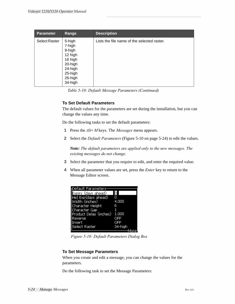
5-24 Manage Messages Rev AA
Videojet 1220/1520 Operator Manual
To Set Default ParametersThe default values for the parameters are set during the installation, but you can change the values any time.
Do the following tasks to set the default parameters:
1 Press the Alt+M keys. The Messages menu appears.
2 Select the Default Parameters (Figure 5-10 on page 5-24) to edit the values.
Note: The default parameters are applied only to the new messages. The existing messages do not change.
3 Select the parameter that you require to edit, and enter the required value.
4 When all parameter values are set, press the Enter key to return to the Message Editor screen.
To Set Message ParametersWhen you create and edit a message, you can change the values for the parameters.
Do the following task to set the Message Parameters:
Select Raster 5-high7-high9-high12 high16 high20-high24-high25-high26-high34-high
Lists the file name of the selected raster.
Parameter Range Description
Table 5-10: Default Message Parameters (Continued)
Figure 5-10: Default Parameters Dialog Box
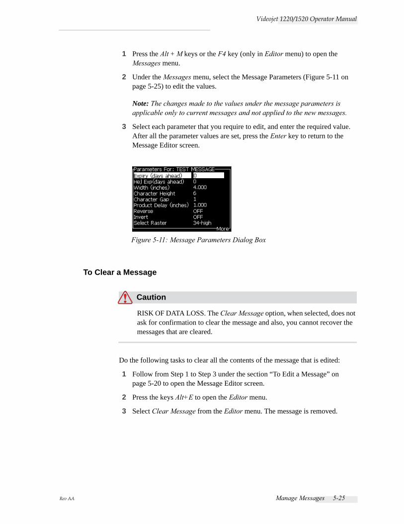
Rev AA Manage Messages 5-25
Videojet 1220/1520 Operator Manual
1 Press the Alt + M keys or the F4 key (only in Editor menu) to open the Messages menu.
2 Under the Messages menu, select the Message Parameters (Figure 5-11 on page 5-25) to edit the values.
Note: The changes made to the values under the message parameters is applicable only to current messages and not applied to the new messages.
3 Select each parameter that you require to edit, and enter the required value. After all the parameter values are set, press the Enter key to return to the Message Editor screen.
To Clear a Message
Caution
RISK OF DATA LOSS. The Clear Message option, when selected, does not ask for confirmation to clear the message and also, you cannot recover the messages that are cleared.
Do the following tasks to clear all the contents of the message that is edited:
1 Follow from Step 1 to Step 3 under the section “To Edit a Message” on page 5-20 to open the Message Editor screen.
2 Press the keys Alt+E to open the Editor menu.
3 Select Clear Message from the Editor menu. The message is removed.
Figure 5-11: Message Parameters Dialog Box

5-26 Manage Messages Rev AA
Videojet 1220/1520 Operator Manual
To Save a MessageDo the following tasks to save a message:
1 Follow from Step 1 to Step 3 under the section “To Edit a Message” on page 5-20 to open the Message Editor screen.
2 Press the keys Alt+E to open the Editor menu.
3 Select the option Save Message to save the message and also continue to edit the message.
To Save a Message and ExitUse either of the two methods to save the message and exit from the Message Editor screen:
• Select Save and Exit from the Editor menu (see Figure 5-14).
Figure 5-12: Clear Message Option
Figure 5-13: Save Message Option
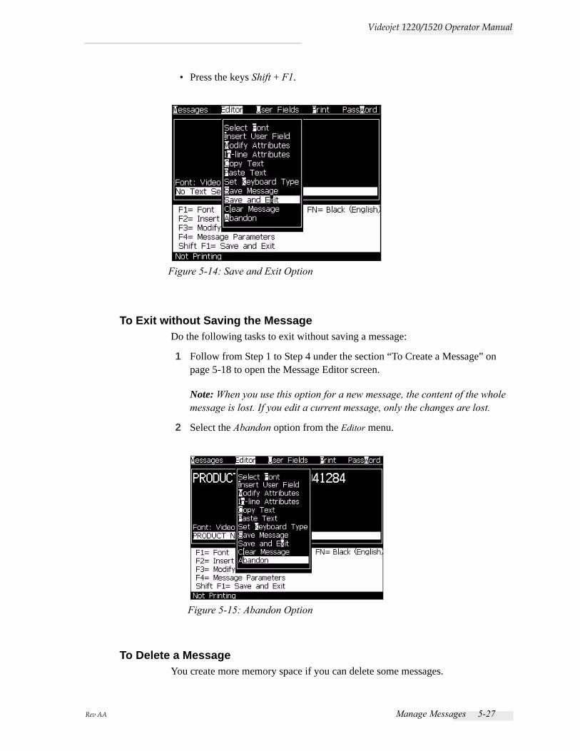
Rev AA Manage Messages 5-27
Videojet 1220/1520 Operator Manual
• Press the keys Shift + F1.
To Exit without Saving the MessageDo the following tasks to exit without saving a message:
1 Follow from Step 1 to Step 4 under the section “To Create a Message” on page 5-18 to open the Message Editor screen.
Note: When you use this option for a new message, the content of the whole message is lost. If you edit a current message, only the changes are lost.
2 Select the Abandon option from the Editor menu.
To Delete a MessageYou create more memory space if you can delete some messages.
Figure 5-14: Save and Exit Option
Figure 5-15: Abandon Option
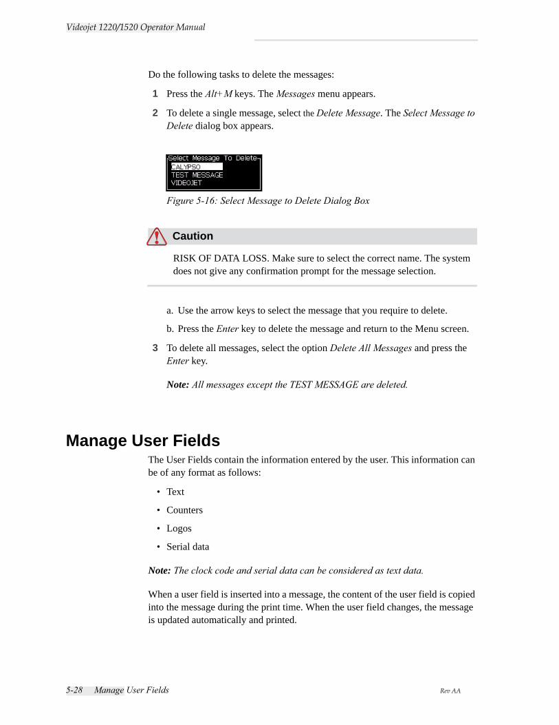
5-28 Manage User Fields Rev AA
Videojet 1220/1520 Operator Manual
Do the following tasks to delete the messages:
1 Press the Alt+M keys. The Messages menu appears.
2 To delete a single message, select the Delete Message. The Select Message to Delete dialog box appears.
Caution
RISK OF DATA LOSS. Make sure to select the correct name. The system does not give any confirmation prompt for the message selection.
a. Use the arrow keys to select the message that you require to delete.
b. Press the Enter key to delete the message and return to the Menu screen.
3 To delete all messages, select the option Delete All Messages and press the Enter key.
Note: All messages except the TEST MESSAGE are deleted.
Manage User FieldsThe User Fields contain the information entered by the user. This information can be of any format as follows:
• Text
• Counters
• Logos
• Serial data
Note: The clock code and serial data can be considered as text data.
When a user field is inserted into a message, the content of the user field is copied into the message during the print time. When the user field changes, the message is updated automatically and printed.
Figure 5-16: Select Message to Delete Dialog Box
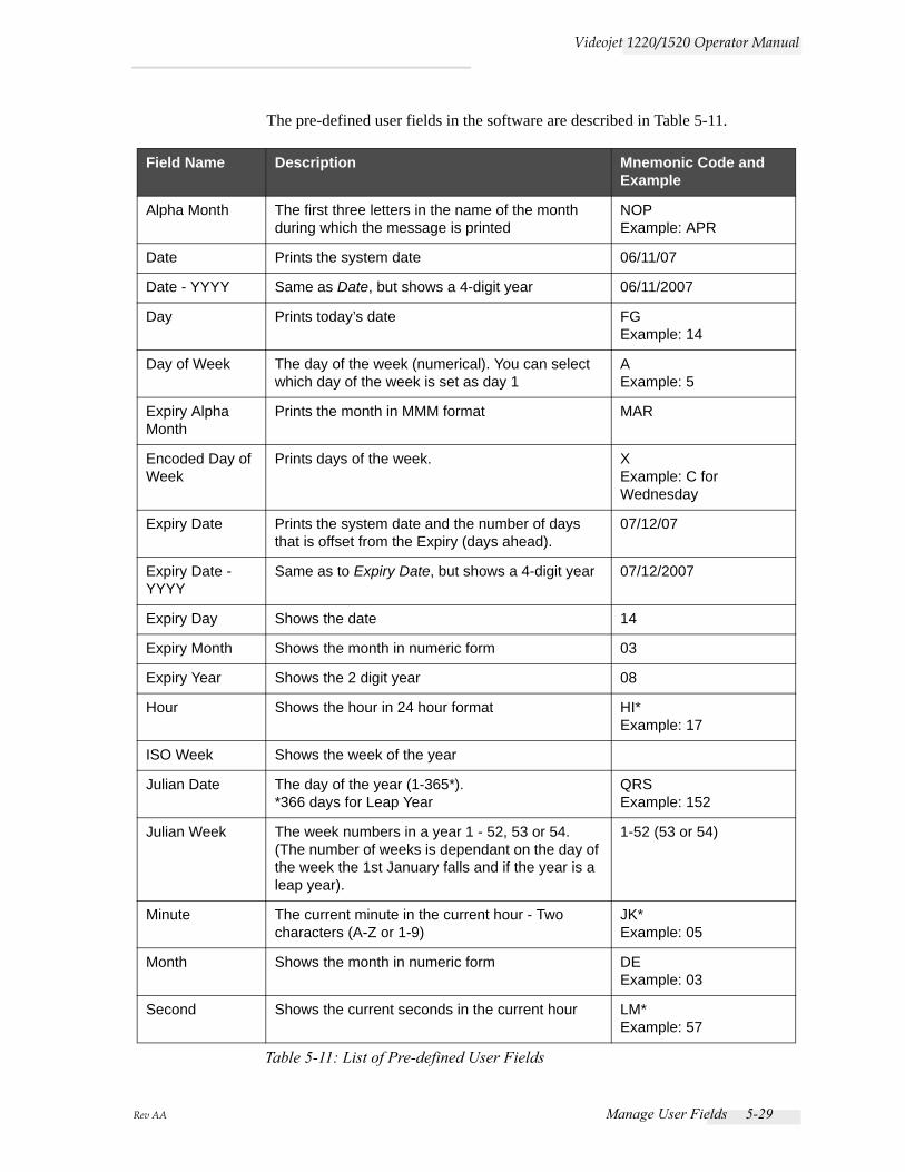
Rev AA Manage User Fields 5-29
Videojet 1220/1520 Operator Manual
The pre-defined user fields in the software are described in Table 5-11.
Field Name Description Mnemonic Code and Example
Alpha Month The first three letters in the name of the month during which the message is printed
NOPExample: APR
Date Prints the system date 06/11/07
Date - YYYY Same as Date, but shows a 4-digit year 06/11/2007
Day Prints today’s date FGExample: 14
Day of Week The day of the week (numerical). You can select which day of the week is set as day 1
AExample: 5
Expiry Alpha Month
Prints the month in MMM format MAR
Encoded Day of Week
Prints days of the week. XExample: C for Wednesday
Expiry Date Prints the system date and the number of days that is offset from the Expiry (days ahead).
07/12/07
Expiry Date - YYYY
Same as to Expiry Date, but shows a 4-digit year 07/12/2007
Expiry Day Shows the date 14
Expiry Month Shows the month in numeric form 03
Expiry Year Shows the 2 digit year 08
Hour Shows the hour in 24 hour format HI*Example: 17
ISO Week Shows the week of the year
Julian Date The day of the year (1-365*).*366 days for Leap Year
QRSExample: 152
Julian Week The week numbers in a year 1 - 52, 53 or 54.(The number of weeks is dependant on the day of the week the 1st January falls and if the year is a leap year).
1-52 (53 or 54)
Minute The current minute in the current hour - Two characters (A-Z or 1-9)
JK*Example: 05
Month Shows the month in numeric form DEExample: 03
Second Shows the current seconds in the current hour LM*Example: 57
Table 5-11: List of Pre-defined User Fields
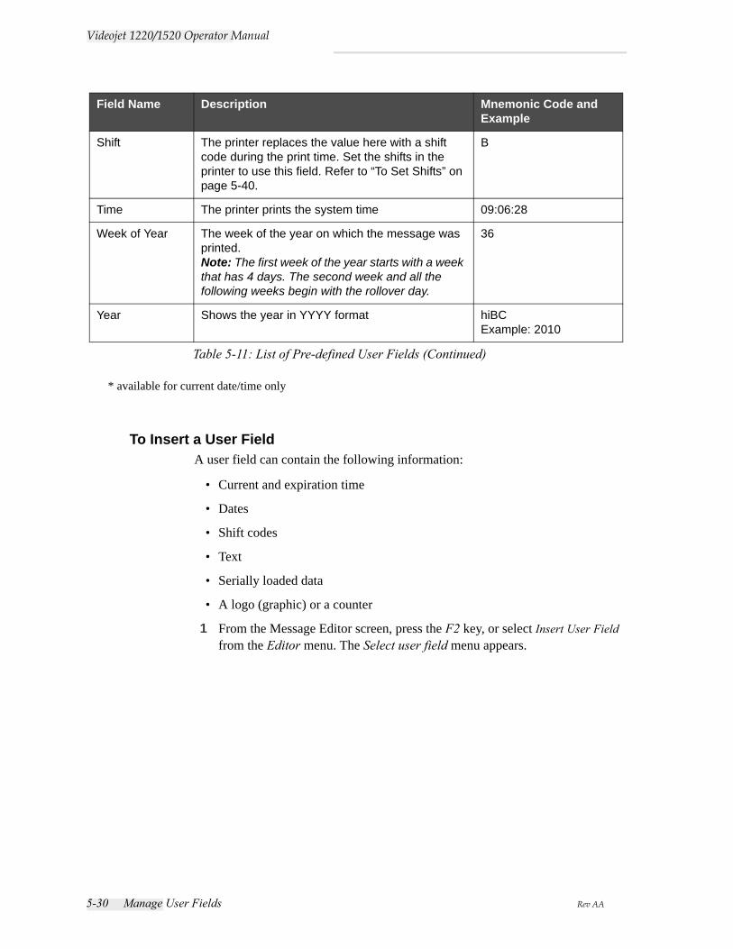
5-30 Manage User Fields Rev AA
Videojet 1220/1520 Operator Manual
* available for current date/time only
To Insert a User FieldA user field can contain the following information:
• Current and expiration time
• Dates
• Shift codes
• Text
• Serially loaded data
• A logo (graphic) or a counter
1 From the Message Editor screen, press the F2 key, or select Insert User Field from the Editor menu. The Select user field menu appears.
Shift The printer replaces the value here with a shift code during the print time. Set the shifts in the printer to use this field. Refer to “To Set Shifts” on page 5-40.
B
Time The printer prints the system time 09:06:28
Week of Year The week of the year on which the message was printed.Note: The first week of the year starts with a week that has 4 days. The second week and all the following weeks begin with the rollover day.
36
Year Shows the year in YYYY format hiBCExample: 2010
Field Name Description Mnemonic Code and Example
Table 5-11: List of Pre-defined User Fields (Continued)
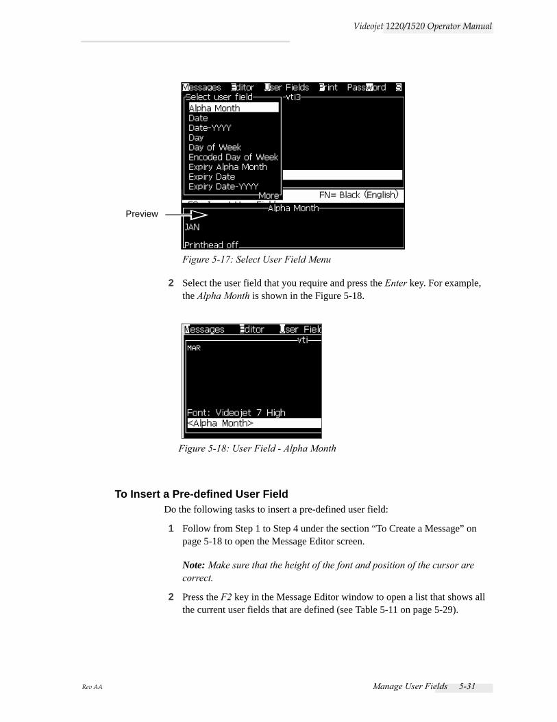
Rev AA Manage User Fields 5-31
Videojet 1220/1520 Operator Manual
2 Select the user field that you require and press the Enter key. For example, the Alpha Month is shown in the Figure 5-18.
To Insert a Pre-defined User FieldDo the following tasks to insert a pre-defined user field:
1 Follow from Step 1 to Step 4 under the section “To Create a Message” on page 5-18 to open the Message Editor screen.
Note: Make sure that the height of the font and position of the cursor are correct.
2 Press the F2 key in the Message Editor window to open a list that shows all the current user fields that are defined (see Table 5-11 on page 5-29).
Figure 5-17: Select User Field Menu
Preview
Figure 5-18: User Field - Alpha Month
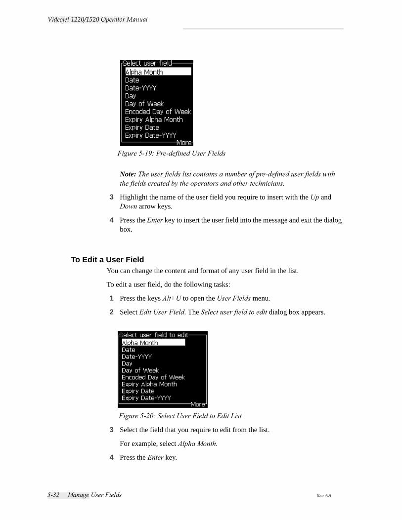
5-32 Manage User Fields Rev AA
Videojet 1220/1520 Operator Manual
Note: The user fields list contains a number of pre-defined user fields with the fields created by the operators and other technicians.
3 Highlight the name of the user field you require to insert with the Up and Down arrow keys.
4 Press the Enter key to insert the user field into the message and exit the dialog box.
To Edit a User FieldYou can change the content and format of any user field in the list.
To edit a user field, do the following tasks:
1 Press the keys Alt+U to open the User Fields menu.
2 Select Edit User Field. The Select user field to edit dialog box appears.
3 Select the field that you require to edit from the list.
For example, select Alpha Month.
4 Press the Enter key.
Figure 5-19: Pre-defined User Fields
Figure 5-20: Select User Field to Edit List
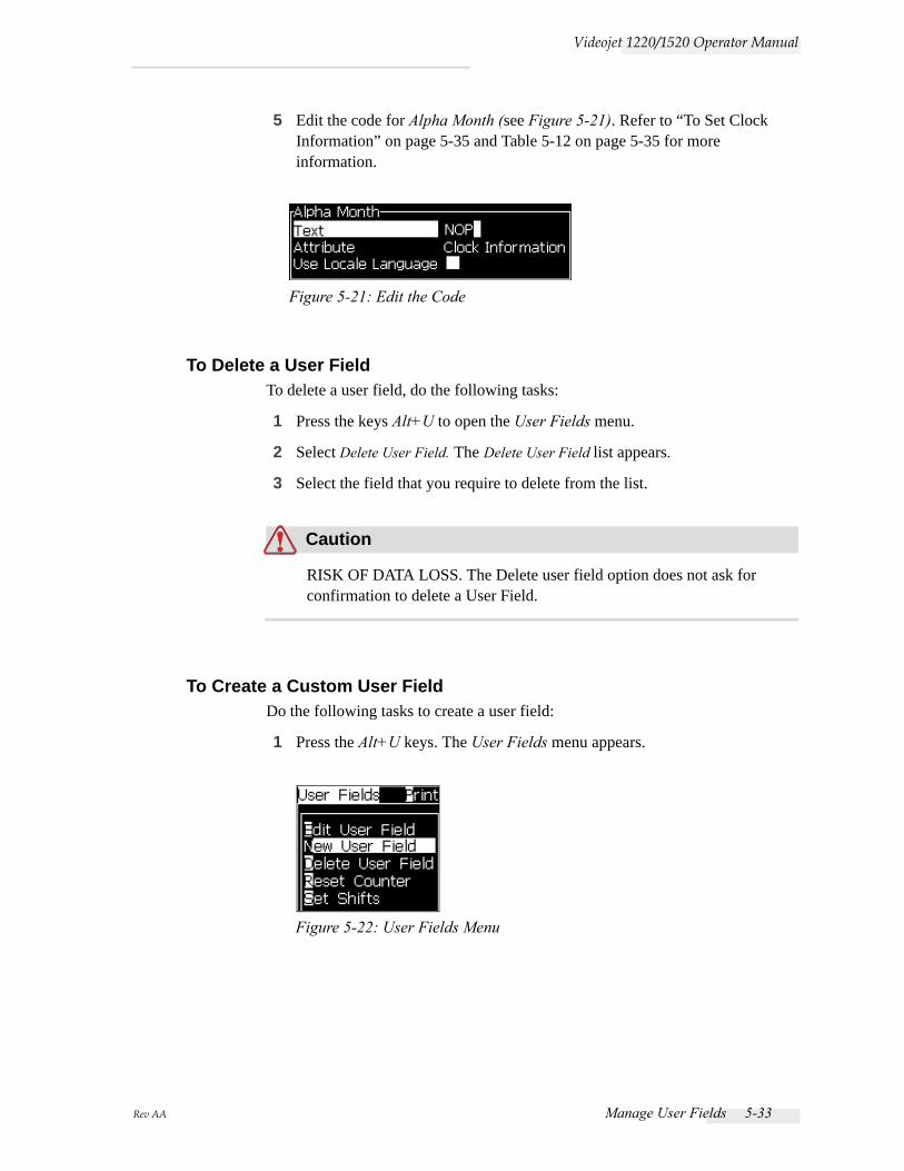
Rev AA Manage User Fields 5-33
Videojet 1220/1520 Operator Manual
5 Edit the code for Alpha Month (see Figure 5-21). Refer to “To Set Clock Information” on page 5-35 and Table 5-12 on page 5-35 for more information.
To Delete a User FieldTo delete a user field, do the following tasks:
1 Press the keys Alt+U to open the User Fields menu.
2 Select Delete User Field. The Delete User Field list appears.
3 Select the field that you require to delete from the list.
Caution
RISK OF DATA LOSS. The Delete user field option does not ask for confirmation to delete a User Field.
To Create a Custom User FieldDo the following tasks to create a user field:
1 Press the Alt+U keys. The User Fields menu appears.
Figure 5-21: Edit the Code
Figure 5-22: User Fields Menu
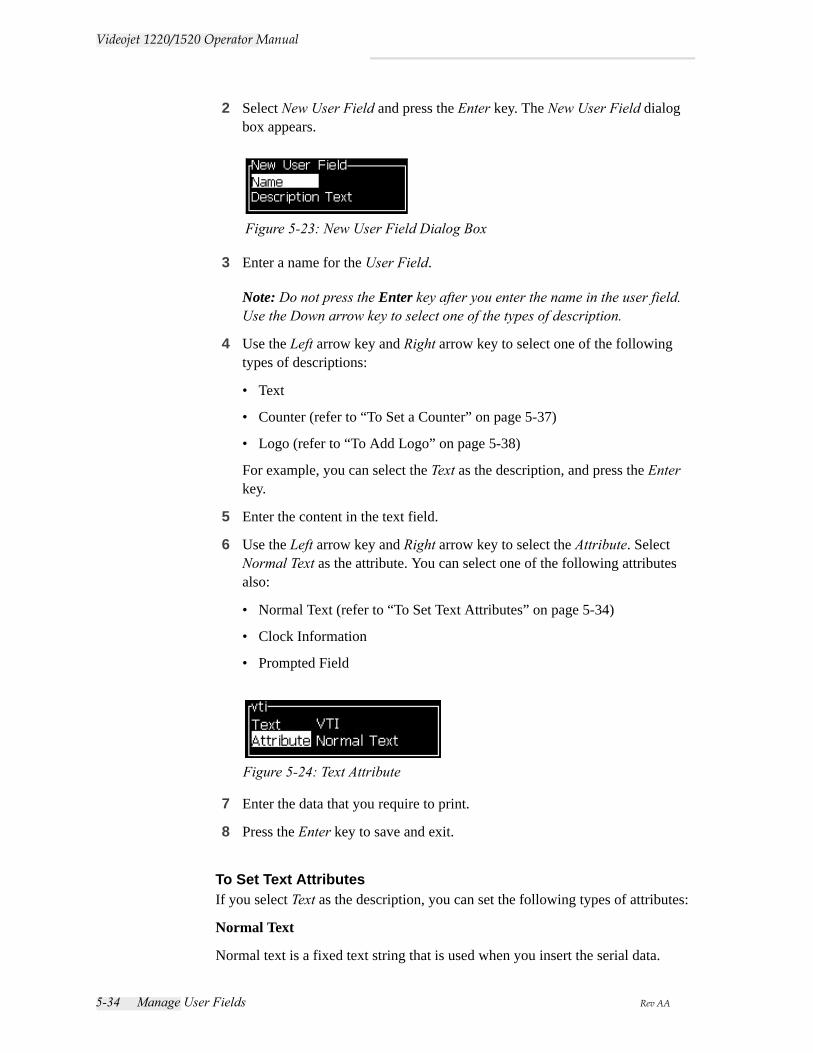
5-34 Manage User Fields Rev AA
Videojet 1220/1520 Operator Manual
2 Select New User Field and press the Enter key. The New User Field dialog box appears.
3 Enter a name for the User Field.
Note: Do not press the Enter key after you enter the name in the user field. Use the Down arrow key to select one of the types of description.
4 Use the Left arrow key and Right arrow key to select one of the following types of descriptions:
• Text
• Counter (refer to “To Set a Counter” on page 5-37)
• Logo (refer to “To Add Logo” on page 5-38)
For example, you can select the Text as the description, and press the Enter key.
5 Enter the content in the text field.
6 Use the Left arrow key and Right arrow key to select the Attribute. Select Normal Text as the attribute. You can select one of the following attributes also:
• Normal Text (refer to “To Set Text Attributes” on page 5-34)
• Clock Information
• Prompted Field
7 Enter the data that you require to print.
8 Press the Enter key to save and exit.
To Set Text AttributesIf you select Text as the description, you can set the following types of attributes:
Normal Text
Normal text is a fixed text string that is used when you insert the serial data.
Figure 5-23: New User Field Dialog Box
Figure 5-24: Text Attribute
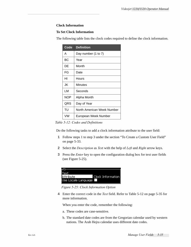
Rev AA Manage User Fields 5-35
Videojet 1220/1520 Operator Manual
Clock Information
To Set Clock Information
The following table lists the clock codes required to define the clock information.
Do the following tasks to add a clock information attribute to the user field:
1 Follow steps 1 to step 3 under the section “To Create a Custom User Field” on page 5-33.
2 Select the Description as Text with the help of Left and Right arrow keys.
3 Press the Enter key to open the configuration dialog box for text user fields (see Figure 5-25).
4 Enter the correct code in the Text field. Refer to Table 5-12 on page 5-35 for more information.
When you enter the code, remember the following:
a. These codes are case-sensitive.
b. The standard date codes are from the Gregorian calendar used by western nations. The Arab Hejra calendar uses different date codes.
Code Definition
A Day number (1 to 7)
BC Year
DE Month
FG Date
HI Hours
JK Minutes
LM Seconds
NOP Alpha Month
QRS Day of Year
TU North American Week Number
VW European Week Number
Table 5-12: Codes and Definitions
Figure 5-25: Clock Information Option
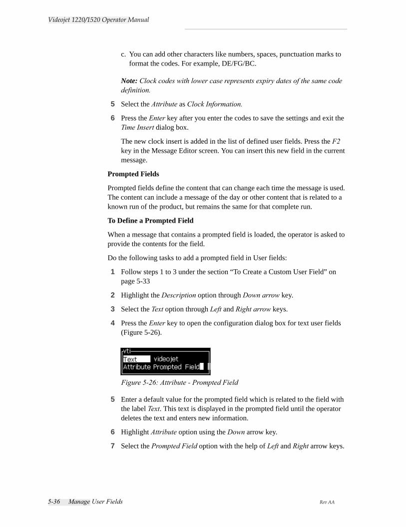
5-36 Manage User Fields Rev AA
Videojet 1220/1520 Operator Manual
c. You can add other characters like numbers, spaces, punctuation marks to format the codes. For example, DE/FG/BC.
Note: Clock codes with lower case represents expiry dates of the same code definition.
5 Select the Attribute as Clock Information.
6 Press the Enter key after you enter the codes to save the settings and exit the Time Insert dialog box.
The new clock insert is added in the list of defined user fields. Press the F2 key in the Message Editor screen. You can insert this new field in the current message.
Prompted Fields
Prompted fields define the content that can change each time the message is used. The content can include a message of the day or other content that is related to a known run of the product, but remains the same for that complete run.
To Define a Prompted Field
When a message that contains a prompted field is loaded, the operator is asked to provide the contents for the field.
Do the following tasks to add a prompted field in User fields:
1 Follow steps 1 to 3 under the section “To Create a Custom User Field” on page 5-33
2 Highlight the Description option through Down arrow key.
3 Select the Text option through Left and Right arrow keys.
4 Press the Enter key to open the configuration dialog box for text user fields (Figure 5-26).
5 Enter a default value for the prompted field which is related to the field with the label Text. This text is displayed in the prompted field until the operator deletes the text and enters new information.
6 Highlight Attribute option using the Down arrow key.
7 Select the Prompted Field option with the help of Left and Right arrow keys.
Figure 5-26: Attribute - Prompted Field
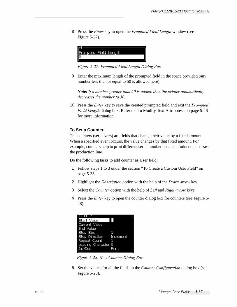
Rev AA Manage User Fields 5-37
Videojet 1220/1520 Operator Manual
8 Press the Enter key to open the Prompted Field Length window (see Figure 5-27).
9 Enter the maximum length of the prompted field in the space provided (any number less than or equal to 50 is allowed here).
Note: If a number greater than 50 is added, then the printer automatically decreases the number to 50.
10 Press the Enter key to save the created prompted field and exit the Prompted Field Length dialog box. Refer to “To Modify Text Attributes” on page 5-46 for more information.
To Set a CounterThe counters (serializers) are fields that change their value by a fixed amount. When a specified event occurs, the value changes by that fixed amount. For example, counters help to print different serial number on each product that passes the production line.
Do the following tasks to add counter as User field:
1 Follow steps 1 to 3 under the section “To Create a Custom User Field” on page 5-33.
2 Highlight the Description option with the help of the Down arrow key.
3 Select the Counter option with the help of Left and Right arrow keys.
4 Press the Enter key to open the counter dialog box for counters (see Figure 5-28).
5 Set the values for all the fields in the Counter Configuration dialog box (see Figure 5-28).
Figure 5-27: Prompted Field Length Dialog Box
Figure 5-28: New Counter Dialog Box
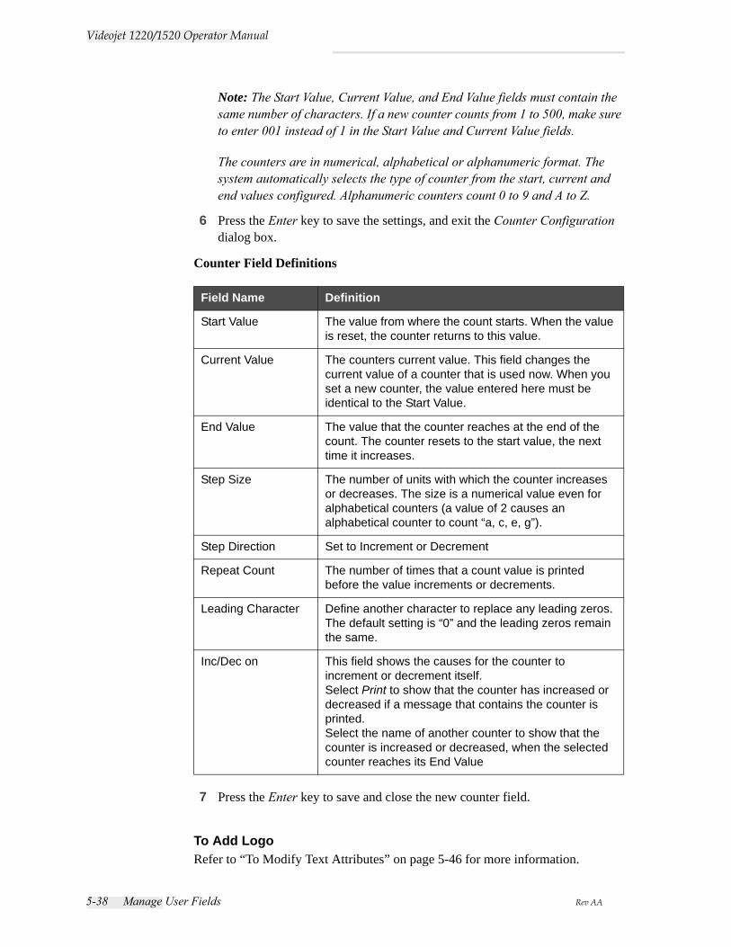
5-38 Manage User Fields Rev AA
Videojet 1220/1520 Operator Manual
Note: The Start Value, Current Value, and End Value fields must contain the same number of characters. If a new counter counts from 1 to 500, make sure to enter 001 instead of 1 in the Start Value and Current Value fields.
The counters are in numerical, alphabetical or alphanumeric format. The system automatically selects the type of counter from the start, current and end values configured. Alphanumeric counters count 0 to 9 and A to Z.
6 Press the Enter key to save the settings, and exit the Counter Configuration dialog box.
Counter Field Definitions
7 Press the Enter key to save and close the new counter field.
To Add LogoRefer to “To Modify Text Attributes” on page 5-46 for more information.
Field Name Definition
Start Value The value from where the count starts. When the value is reset, the counter returns to this value.
Current Value The counters current value. This field changes the current value of a counter that is used now. When you set a new counter, the value entered here must be identical to the Start Value.
End Value The value that the counter reaches at the end of the count. The counter resets to the start value, the next time it increases.
Step Size The number of units with which the counter increases or decreases. The size is a numerical value even for alphabetical counters (a value of 2 causes an alphabetical counter to count “a, c, e, g”).
Step Direction Set to Increment or Decrement
Repeat Count The number of times that a count value is printed before the value increments or decrements.
Leading Character Define another character to replace any leading zeros. The default setting is “0” and the leading zeros remain the same.
Inc/Dec on This field shows the causes for the counter to increment or decrement itself. Select Print to show that the counter has increased or decreased if a message that contains the counter is printed.Select the name of another counter to show that the counter is increased or decreased, when the selected counter reaches its End Value
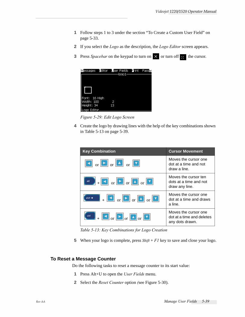
Rev AA Manage User Fields 5-39
Videojet 1220/1520 Operator Manual
1 Follow steps 1 to 3 under the section “To Create a Custom User Field” on page 5-33.
2 If you select the Logo as the description, the Logo Editor screen appears.
3 Press Spacebar on the keypad to turn on or turn off the cursor.
4 Create the logo by drawing lines with the help of the key combinations shown in Table 5-13 on page 5-39.
5 When your logo is complete, press Shift + F1 key to save and close your logo.
To Reset a Message CounterDo the following tasks to reset a message counter to its start value:
1 Press Alt+U to open the User Fields menu.
2 Select the Reset Counter option (see Figure 5-30).
Key Combination Cursor Movement
or or or Moves the cursor one dot at a time and not draw a line.
+ or or or Moves the cursor ten dots at a time and not draw any line.
+ or or or Moves the cursor one dot at a time and draws a line.
+ or or or Moves the cursor one dot at a time and deletes any dots drawn.
Table 5-13: Key Combinations for Logo Creation
Figure 5-29: Edit Logo Screen
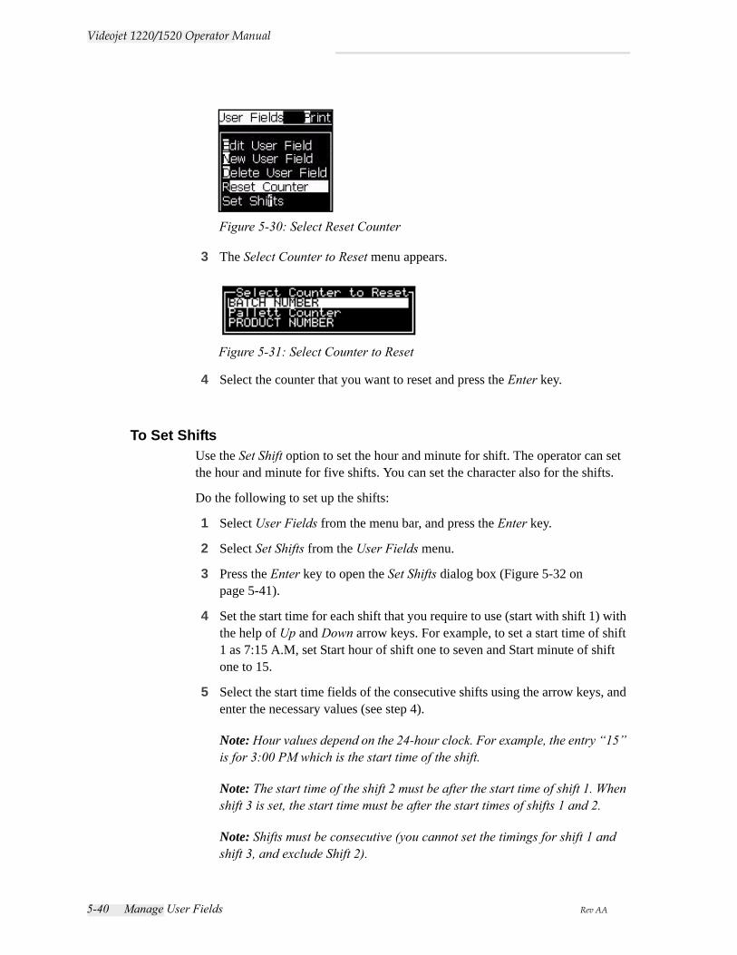
5-40 Manage User Fields Rev AA
Videojet 1220/1520 Operator Manual
3 The Select Counter to Reset menu appears.
4 Select the counter that you want to reset and press the Enter key.
To Set ShiftsUse the Set Shift option to set the hour and minute for shift. The operator can set the hour and minute for five shifts. You can set the character also for the shifts.
Do the following to set up the shifts:
1 Select User Fields from the menu bar, and press the Enter key.
2 Select Set Shifts from the User Fields menu.
3 Press the Enter key to open the Set Shifts dialog box (Figure 5-32 on page 5-41).
4 Set the start time for each shift that you require to use (start with shift 1) with the help of Up and Down arrow keys. For example, to set a start time of shift 1 as 7:15 A.M, set Start hour of shift one to seven and Start minute of shift one to 15.
5 Select the start time fields of the consecutive shifts using the arrow keys, and enter the necessary values (see step 4).
Note: Hour values depend on the 24-hour clock. For example, the entry “15” is for 3:00 PM which is the start time of the shift.
Note: The start time of the shift 2 must be after the start time of shift 1. When shift 3 is set, the start time must be after the start times of shifts 1 and 2.
Note: Shifts must be consecutive (you cannot set the timings for shift 1 and shift 3, and exclude Shift 2).
Figure 5-30: Select Reset Counter
Figure 5-31: Select Counter to Reset
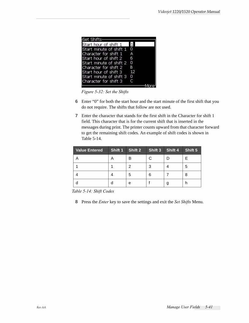
Rev AA Manage User Fields 5-41
Videojet 1220/1520 Operator Manual
6 Enter “0” for both the start hour and the start minute of the first shift that you do not require. The shifts that follow are not used.
7 Enter the character that stands for the first shift in the Character for shift 1 field. This character that is for the current shift that is inserted in the messages during print. The printer counts upward from that character forward to get the remaining shift codes. An example of shift codes is shown in Table 5-14.
8 Press the Enter key to save the settings and exit the Set Shifts Menu.
Value Entered Shift 1 Shift 2 Shift 3 Shift 4 Shift 5
A A B C D E
1 1 2 3 4 5
4 4 5 6 7 8
d d e f g h
Table 5-14: Shift Codes
Figure 5-32: Set the Shifts

5-42 Manage Text Rev AA
Videojet 1220/1520 Operator Manual
Manage Text
To Change Font CaseThe required message can contain both upper and lower case characters. The keys on the keypad that control the case of the entered characters are shown in Table 5-15.
To Set Font HeightYou can change the height of the font in a message and can have more than one size in a message. The number of lines in a message depends on the size of the font selected and the model of the printer. Refer to“Font Specifications and Line Speeds” on page A-9 for more information.
Press the F1 key until you get the required height of the font (see Figure 5-33).
Do the following tasks to set the height of the font from the Editor menu.
1 Press the Alt+E keys or press F1. The Editor menu appears (see Figure 5-34).
Key Function
The Caps Key changes the case of the next character entered.
The Caps Lock key changes the default case.
Table 5-15: The keys to Change the Case of the Fonts
Figure 5-33: Select Font Height

Rev AA Manage Text 5-43
Videojet 1220/1520 Operator Manual
2 Select the Select Font option. The Select Font menu appears. Use the Up and Down arrow keys to select the height of the font.
3 Select the font height, and press the Enter key.
To Select ContentThe editor automatically selects the block of text that you enter. This feature is referred to as Default Text Selection (Figure 5-36). If this feature is not available, the message No Text Selected appears in that area.
Figure 5-34: Editor Menu
Figure 5-35: Select Font List
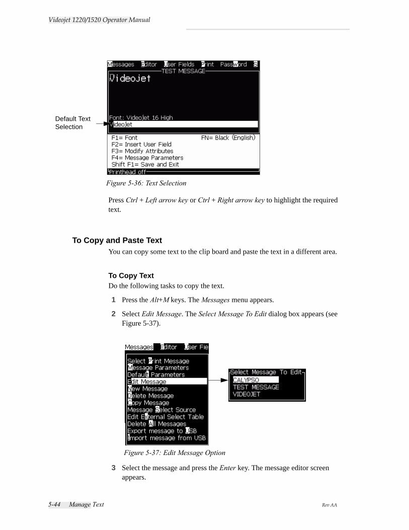
5-44 Manage Text Rev AA
Videojet 1220/1520 Operator Manual
Press Ctrl + Left arrow key or Ctrl + Right arrow key to highlight the required text.
To Copy and Paste TextYou can copy some text to the clip board and paste the text in a different area.
To Copy TextDo the following tasks to copy the text.
1 Press the Alt+M keys. The Messages menu appears.
2 Select Edit Message. The Select Message To Edit dialog box appears (see Figure 5-37).
3 Select the message and press the Enter key. The message editor screen appears.
Figure 5-36: Text Selection
Default Text Selection
Figure 5-37: Edit Message Option
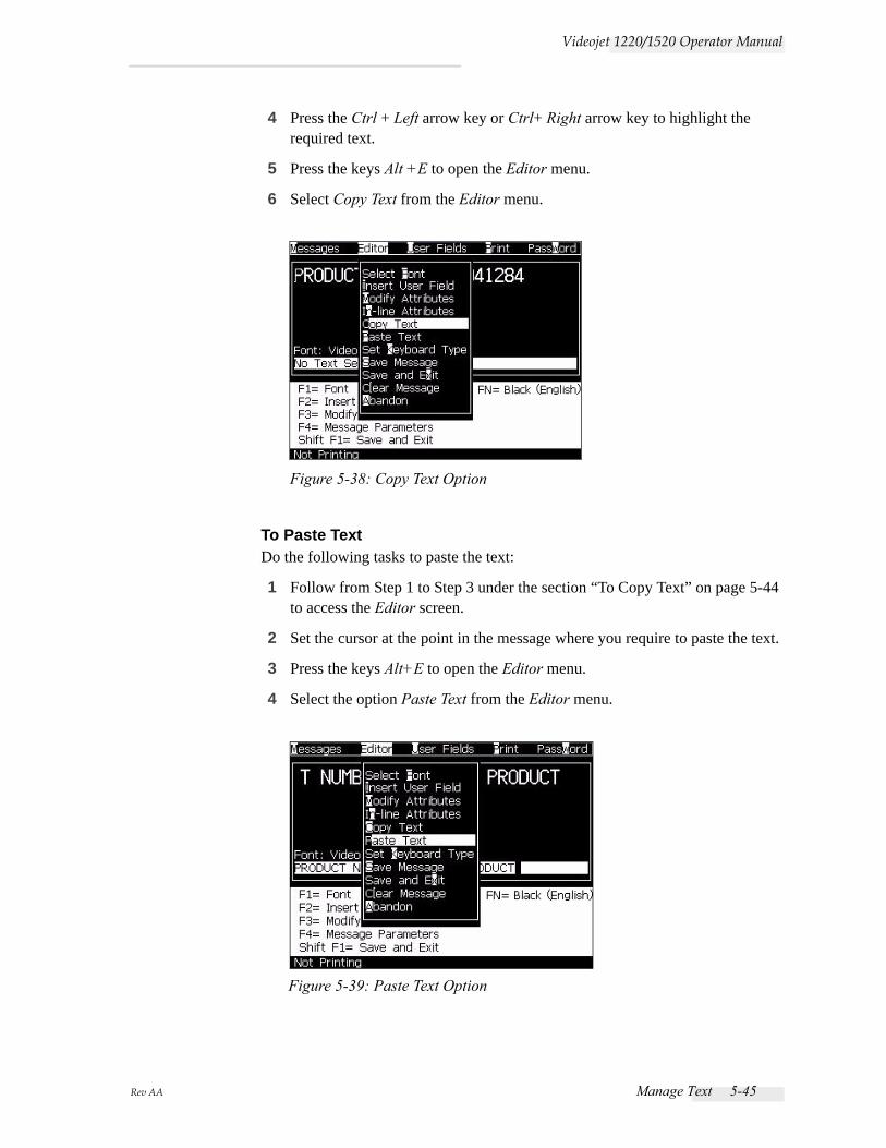
Rev AA Manage Text 5-45
Videojet 1220/1520 Operator Manual
4 Press the Ctrl + Left arrow key or Ctrl+ Right arrow key to highlight the required text.
5 Press the keys Alt +E to open the Editor menu.
6 Select Copy Text from the Editor menu.
To Paste TextDo the following tasks to paste the text:
1 Follow from Step 1 to Step 3 under the section “To Copy Text” on page 5-44 to access the Editor screen.
2 Set the cursor at the point in the message where you require to paste the text.
3 Press the keys Alt+E to open the Editor menu.
4 Select the option Paste Text from the Editor menu.
Figure 5-38: Copy Text Option
Figure 5-39: Paste Text Option

5-46 Manage Text Rev AA
Videojet 1220/1520 Operator Manual
To Modify Text AttributesThere are two methods to change the text attributes:
• Modify Attributes - The Modify Attributes option allows the operator to change the attributes of the selected content displayed in the editor screen (refer to “To Modify Attributes” on page 5-47).
• In-line Attributes - The In-line Attributes option applies the changes only to the new text entered at the cursor and any selected text is ignored (refer to “To Apply In-line Attributes” on page 5-48).
The different attributes are recorded in Table 5-16.
Options Functions Example
Invert Turns the text upside down.
Reverse Turns the text back to front.
Use Custom Font(Videojet 1520 only)
Contact Videojet for more information.
Clock Changes the text to the date or time information.For example, if you enter FG-DE-BC, you get the date in dd-mm-yy format.
Double Dot Each raster of selected text is made to print two times that forms bolder character.Example: See “Bold Text” in the illustration.
Triple Dot Each raster of selected text is made to print three times to make the character very bolder.Example: See “Very Bold Text” in the illustration.
Tower print The printer can print single line (5 x 7) in the vertical direction.
Barcode(Videojet 1520 only)
Turns the inserted text into the format of the required barcode.
Table 5-16: Options to Modify Attributes
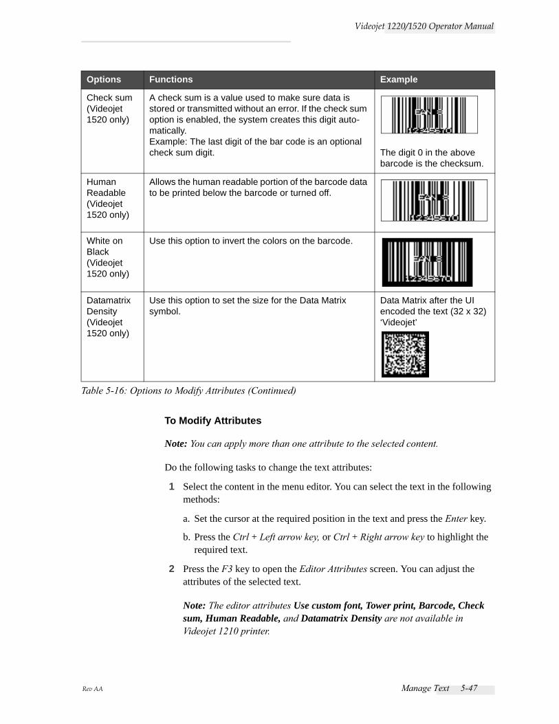
Rev AA Manage Text 5-47
Videojet 1220/1520 Operator Manual
To Modify Attributes
Note: You can apply more than one attribute to the selected content.
Do the following tasks to change the text attributes:
1 Select the content in the menu editor. You can select the text in the following methods:
a. Set the cursor at the required position in the text and press the Enter key.
b. Press the Ctrl + Left arrow key, or Ctrl + Right arrow key to highlight the required text.
2 Press the F3 key to open the Editor Attributes screen. You can adjust the attributes of the selected text.
Note: The editor attributes Use custom font, Tower print, Barcode, Check sum, Human Readable, and Datamatrix Density are not available in Videojet 1210 printer.
Check sum(Videojet 1520 only)
A check sum is a value used to make sure data is stored or transmitted without an error. If the check sum option is enabled, the system creates this digit auto-matically.Example: The last digit of the bar code is an optional check sum digit. The digit 0 in the above
barcode is the checksum.
Human Readable(Videojet 1520 only)
Allows the human readable portion of the barcode data to be printed below the barcode or turned off.
White on Black(Videojet 1520 only)
Use this option to invert the colors on the barcode.
Datamatrix Density(Videojet 1520 only)
Use this option to set the size for the Data Matrix symbol.
Data Matrix after the UI encoded the text (32 x 32) ‘Videojet’
Options Functions Example
Table 5-16: Options to Modify Attributes (Continued)
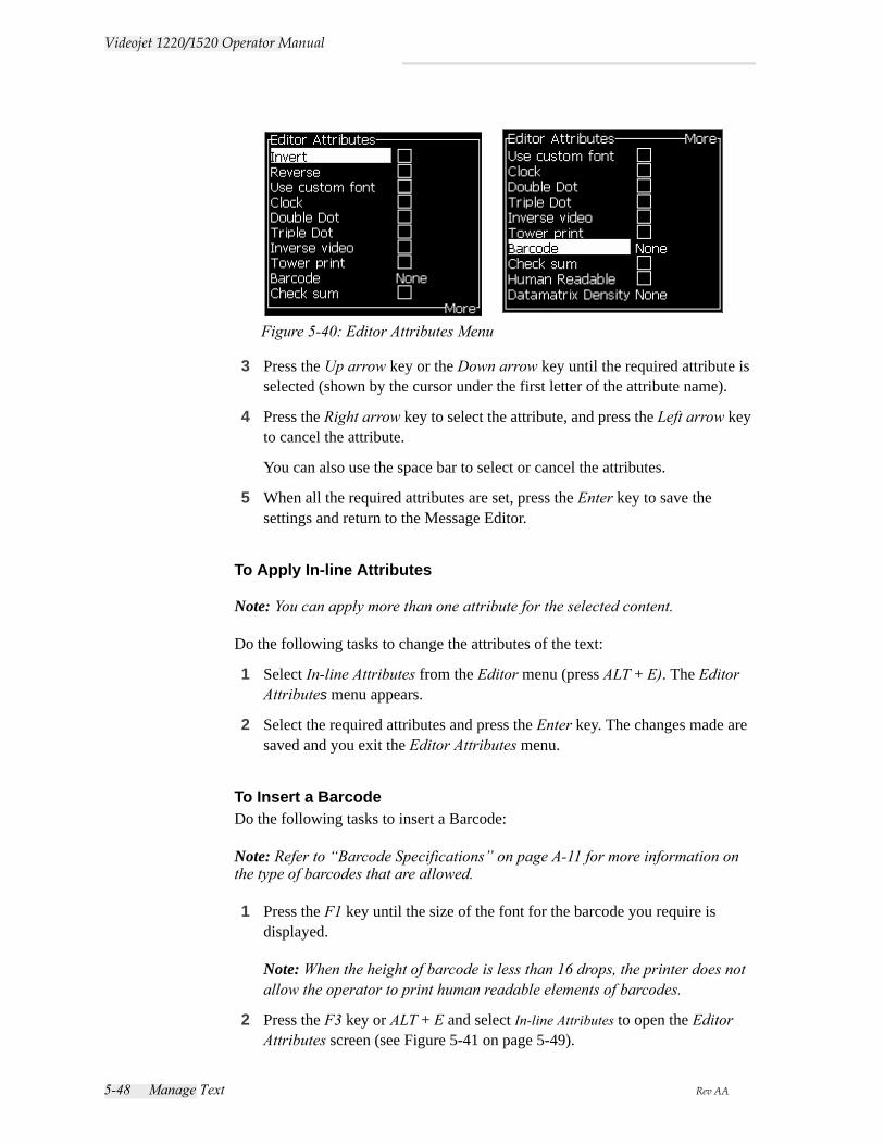
5-48 Manage Text Rev AA
Videojet 1220/1520 Operator Manual
3 Press the Up arrow key or the Down arrow key until the required attribute is selected (shown by the cursor under the first letter of the attribute name).
4 Press the Right arrow key to select the attribute, and press the Left arrow key to cancel the attribute.
You can also use the space bar to select or cancel the attributes.
5 When all the required attributes are set, press the Enter key to save the settings and return to the Message Editor.
To Apply In-line Attributes
Note: You can apply more than one attribute for the selected content.
Do the following tasks to change the attributes of the text:
1 Select In-line Attributes from the Editor menu (press ALT + E). The Editor Attributes menu appears.
2 Select the required attributes and press the Enter key. The changes made are saved and you exit the Editor Attributes menu.
To Insert a BarcodeDo the following tasks to insert a Barcode:
Note: Refer to “Barcode Specifications” on page A-11 for more information on the type of barcodes that are allowed.
1 Press the F1 key until the size of the font for the barcode you require is displayed.
Note: When the height of barcode is less than 16 drops, the printer does not allow the operator to print human readable elements of barcodes.
2 Press the F3 key or ALT + E and select In-line Attributes to open the Editor Attributes screen (see Figure 5-41 on page 5-49).
Figure 5-40: Editor Attributes Menu

Rev AA Manage Text 5-49
Videojet 1220/1520 Operator Manual
3 Use the Up and Down arrow keys to highlight the Barcode option.
4 Use the Right arrow key or Left arrow key to select the required barcode.
5 If you require to include a check sum for error correction in the barcode, then use the Right arrow key or Left arrow key to select the box.
Note: If you cannot highlight the check sum now, the current setting is necessary for the type of barcode selected.
6 If you require a human readable version of the barcode to appear near the barcode, press the Right arrow or Left arrow key to select the relative position on the Human Readable attribute:
Note: If you cannot highlight Human Readable now, the current setting is necessary for the type of barcode selected and size of the font.
7 Press the Enter key to save the barcode and exit the Editor Attributes screen.
8 Enter the barcode data at the cursor. A graphical representation of the barcode now appears in the Message Editor window.
For example, you can see some useful information about the input allowed for the type of barcode (EAN-8) selected.
Note: You can insert a user field into a barcode if all the characters in this field are valid for the type of barcode.
9 Finish the barcode edition and move the cursor away with the Left arrow or Right arrow key.
Figure 5-41: Select the Type of Barcode
Figure 5-42: Bar Code
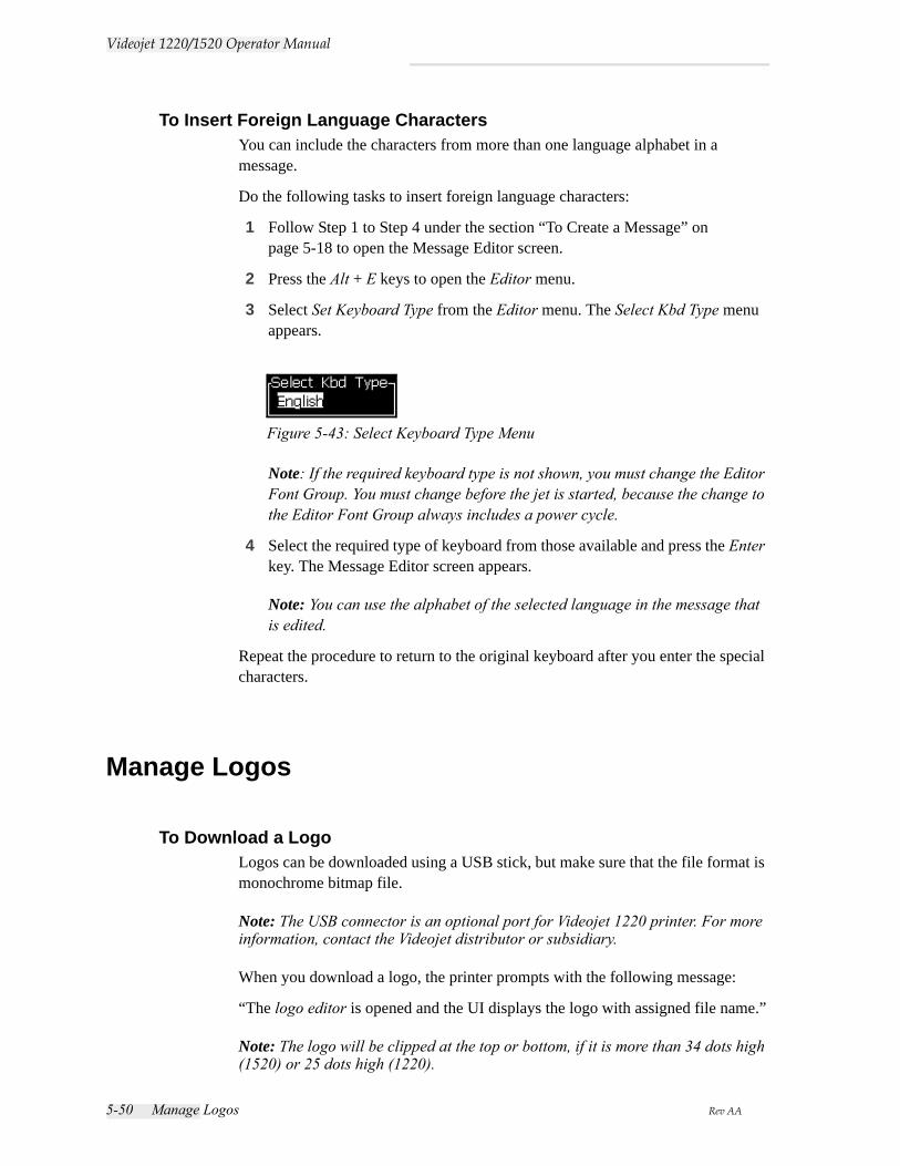
5-50 Manage Logos Rev AA
Videojet 1220/1520 Operator Manual
To Insert Foreign Language CharactersYou can include the characters from more than one language alphabet in a message.
Do the following tasks to insert foreign language characters:
1 Follow Step 1 to Step 4 under the section “To Create a Message” on page 5-18 to open the Message Editor screen.
2 Press the Alt + E keys to open the Editor menu.
3 Select Set Keyboard Type from the Editor menu. The Select Kbd Type menu appears.
Note: If the required keyboard type is not shown, you must change the Editor Font Group. You must change before the jet is started, because the change to the Editor Font Group always includes a power cycle.
4 Select the required type of keyboard from those available and press the Enter key. The Message Editor screen appears.
Note: You can use the alphabet of the selected language in the message that is edited.
Repeat the procedure to return to the original keyboard after you enter the special characters.
Manage Logos
To Download a LogoLogos can be downloaded using a USB stick, but make sure that the file format is monochrome bitmap file.
Note: The USB connector is an optional port for Videojet 1220 printer. For more information, contact the Videojet distributor or subsidiary.
When you download a logo, the printer prompts with the following message:
“The logo editor is opened and the UI displays the logo with assigned file name.”
Note: The logo will be clipped at the top or bottom, if it is more than 34 dots high (1520) or 25 dots high (1220).
Figure 5-43: Select Keyboard Type Menu

Rev AA Manage Logos 5-51
Videojet 1220/1520 Operator Manual
You can edit the logo on the printer, or use the Shift + F1 option to save the logo with the same name. The logo is available under the User Fields to insert into the messages.
Note: If you try to download a type of file (or folder) which does not match the file types, in the above table, the printer displays the following if the Enter key is pressed "Unsupported File Type".
To Create a Logo in Microsoft Paint Application1 Open the Microsoft Paint application. A new page opens by default.
2 Navigate to View > Zoom > Custom. The Custom Zoom (Figure 5-44) dialog box appears.
3 Select 800% under Zoom to. Click the OK button.
4 Navigate to View > Zoom > Show Grid to activate the grid for the page.
5 Navigate to Image > Attributes to set the size of the message. Set the necessary message size. The message height should not be more than 34 for 1520 and not more than 24 for 1220. This menu allows the user to:
a. Verify the format of the existing messages.
b. Pre-set the message size to avoid editing the image later
c. Select the colour format of the image as Black and White.(See Figure 5-45 on page 5-52)
Figure 5-44: Custom Zoom
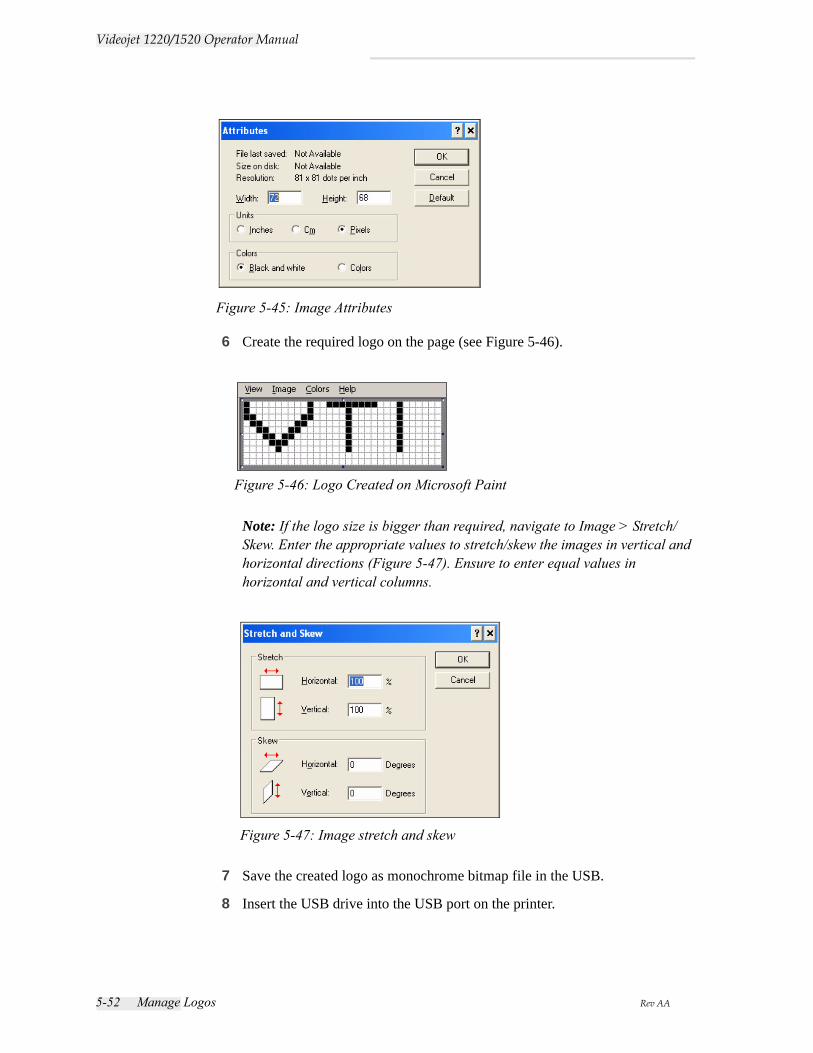
5-52 Manage Logos Rev AA
Videojet 1220/1520 Operator Manual
6 Create the required logo on the page (see Figure 5-46).
Note: If the logo size is bigger than required, navigate to Image > Stretch/Skew. Enter the appropriate values to stretch/skew the images in vertical and horizontal directions (Figure 5-47). Ensure to enter equal values in horizontal and vertical columns.
7 Save the created logo as monochrome bitmap file in the USB.
8 Insert the USB drive into the USB port on the printer.
Figure 5-45: Image Attributes
Figure 5-46: Logo Created on Microsoft Paint
Figure 5-47: Image stretch and skew
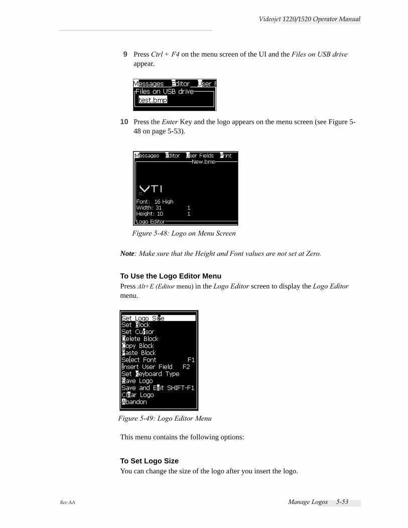
Rev AA Manage Logos 5-53
Videojet 1220/1520 Operator Manual
9 Press Ctrl + F4 on the menu screen of the UI and the Files on USB drive appear.
10 Press the Enter Key and the logo appears on the menu screen (see Figure 5-48 on page 5-53).
Note: Make sure that the Height and Font values are not set at Zero.
To Use the Logo Editor MenuPress Alt+E (Editor menu) in the Logo Editor screen to display the Logo Editor menu.
This menu contains the following options:
To Set Logo SizeYou can change the size of the logo after you insert the logo.
Figure 5-48: Logo on Menu Screen
Figure 5-49: Logo Editor Menu
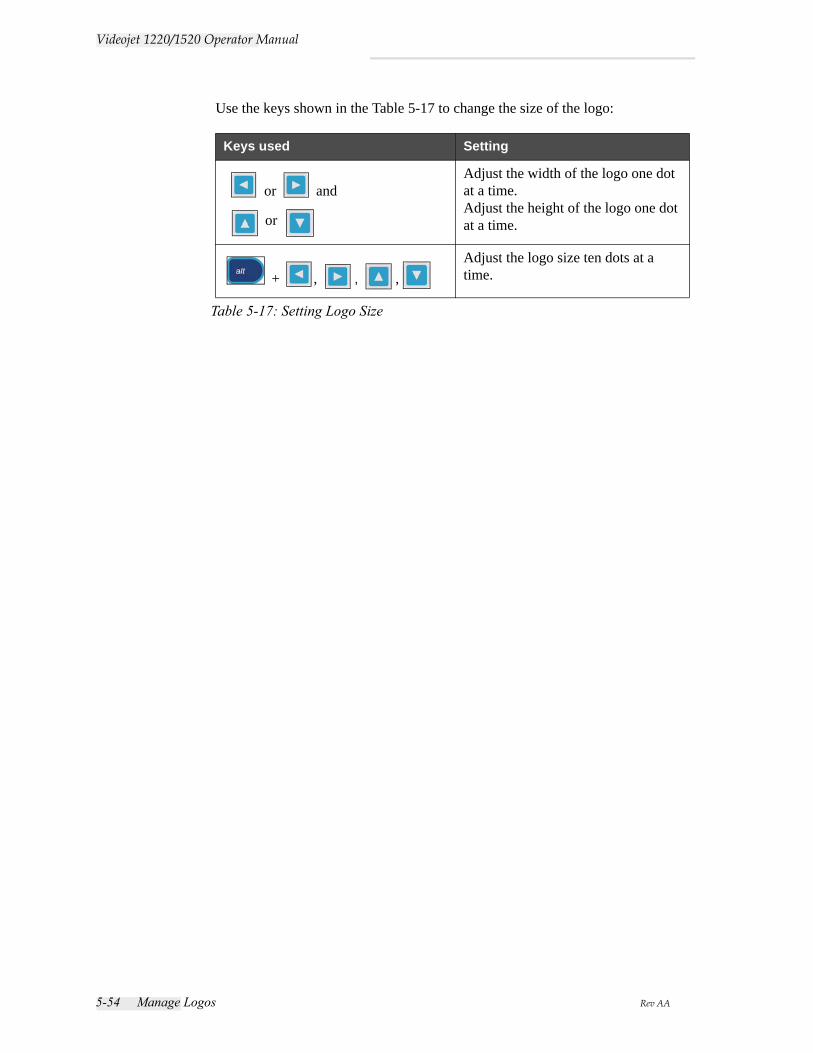
5-54 Manage Logos Rev AA
Videojet 1220/1520 Operator Manual
Use the keys shown in the Table 5-17 to change the size of the logo:
Keys used Setting
or and
or
Adjust the width of the logo one dot at a time.Adjust the height of the logo one dot at a time.
+ , , , Adjust the logo size ten dots at a time.
Table 5-17: Setting Logo Size
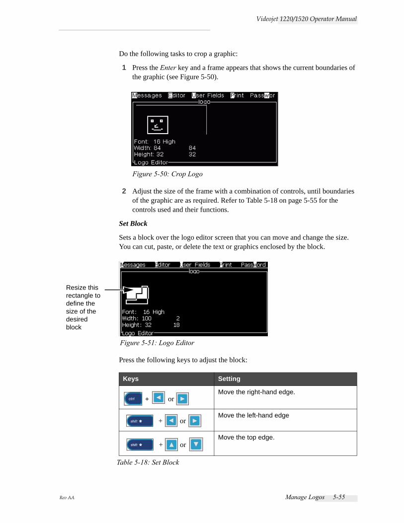
Rev AA Manage Logos 5-55
Videojet 1220/1520 Operator Manual
Do the following tasks to crop a graphic:
1 Press the Enter key and a frame appears that shows the current boundaries of the graphic (see Figure 5-50).
2 Adjust the size of the frame with a combination of controls, until boundaries of the graphic are as required. Refer to Table 5-18 on page 5-55 for the controls used and their functions.
Set Block
Sets a block over the logo editor screen that you can move and change the size. You can cut, paste, or delete the text or graphics enclosed by the block.
Press the following keys to adjust the block:
Keys Setting
+ or Move the right-hand edge.
+ or Move the left-hand edge
+ or Move the top edge.
Table 5-18: Set Block
Figure 5-50: Crop Logo
Figure 5-51: Logo Editor
Resize this rectangle to define the size of the desired block
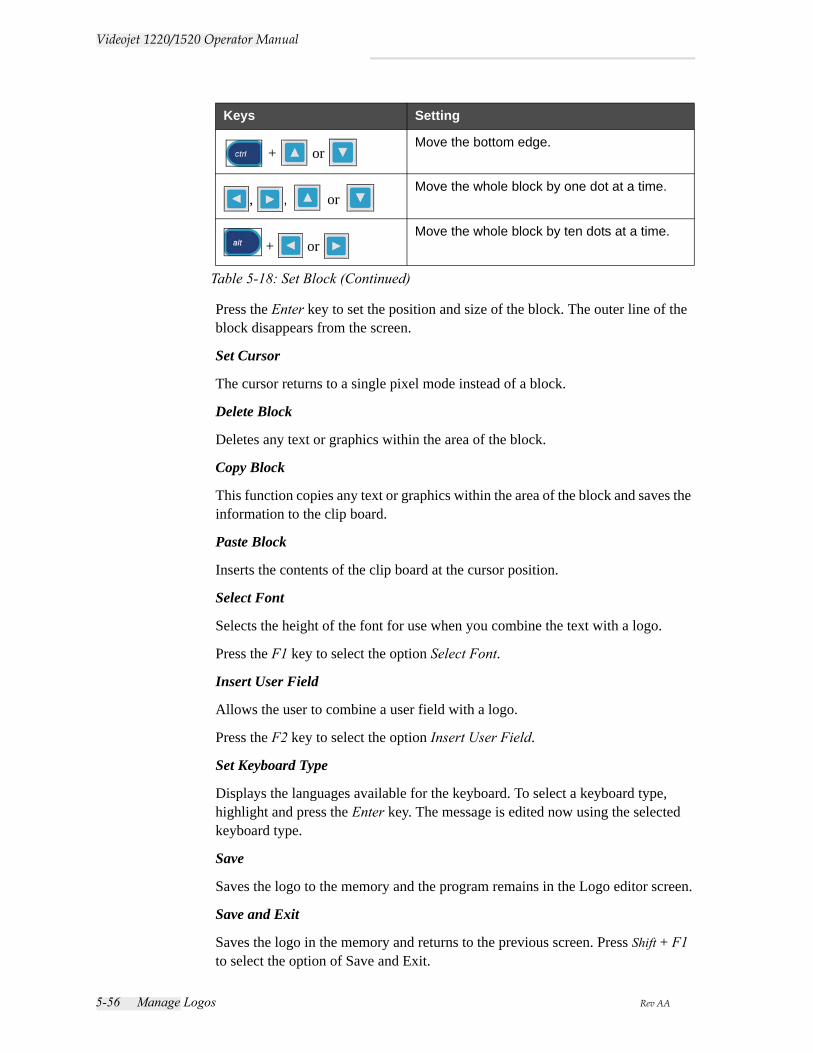
5-56 Manage Logos Rev AA
Videojet 1220/1520 Operator Manual
Press the Enter key to set the position and size of the block. The outer line of the block disappears from the screen.
Set Cursor
The cursor returns to a single pixel mode instead of a block.
Delete Block
Deletes any text or graphics within the area of the block.
Copy Block
This function copies any text or graphics within the area of the block and saves the information to the clip board.
Paste Block
Inserts the contents of the clip board at the cursor position.
Select Font
Selects the height of the font for use when you combine the text with a logo.
Press the F1 key to select the option Select Font.
Insert User Field
Allows the user to combine a user field with a logo.
Press the F2 key to select the option Insert User Field.
Set Keyboard Type
Displays the languages available for the keyboard. To select a keyboard type, highlight and press the Enter key. The message is edited now using the selected keyboard type.
Save
Saves the logo to the memory and the program remains in the Logo editor screen.
Save and Exit
Saves the logo in the memory and returns to the previous screen. Press Shift + F1 to select the option of Save and Exit.
+ or Move the bottom edge.
, , or Move the whole block by one dot at a time.
+ or Move the whole block by ten dots at a time.
Keys Setting
Table 5-18: Set Block (Continued)
Rev AA Manage Logos 5-57
Videojet 1220/1520 Operator Manual
Clear Logo
Removes the logo that is edited at this time or created from the Logo Editor screen.
Abandon
Leaves the logo edition activity without saving any changes, and returns to the Message Editor Screen.
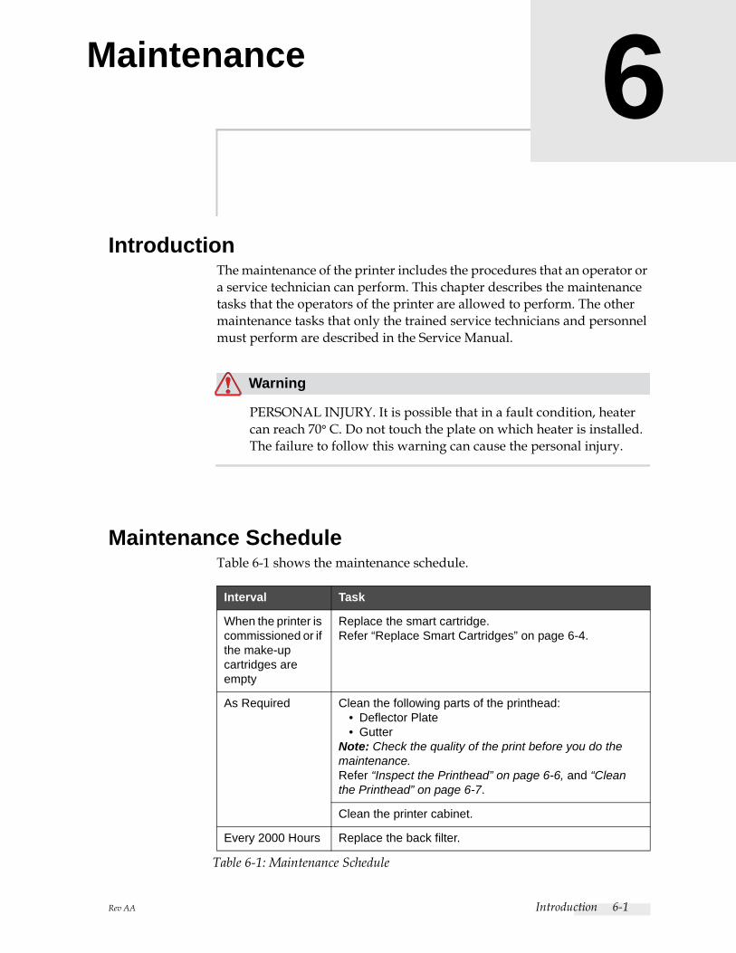
Rev AA Introduction 6-1
6Maintenance
IntroductionThe maintenance of the printer includes the procedures that an operator or a service technician can perform. This chapter describes the maintenance tasks that the operators of the printer are allowed to perform. The other maintenance tasks that only the trained service technicians and personnel must perform are described in the Service Manual.
Warning
PERSONAL INJURY. It is possible that in a fault condition, heater can reach 70° C. Do not touch the plate on which heater is installed. The failure to follow this warning can cause the personal injury.
Maintenance ScheduleTable 6-1 shows the maintenance schedule.
Interval Task
When the printer is commissioned or if the make-up cartridges are empty
Replace the smart cartridge.Refer “Replace Smart Cartridges” on page 6-4.
As Required Clean the following parts of the printhead:• Deflector Plate• Gutter
Note: Check the quality of the print before you do the maintenance.Refer “Inspect the Printhead” on page 6-6, and “Clean the Printhead” on page 6-7.
Clean the printer cabinet.
Every 2000 Hours Replace the back filter.
Table 6-1: Maintenance Schedule
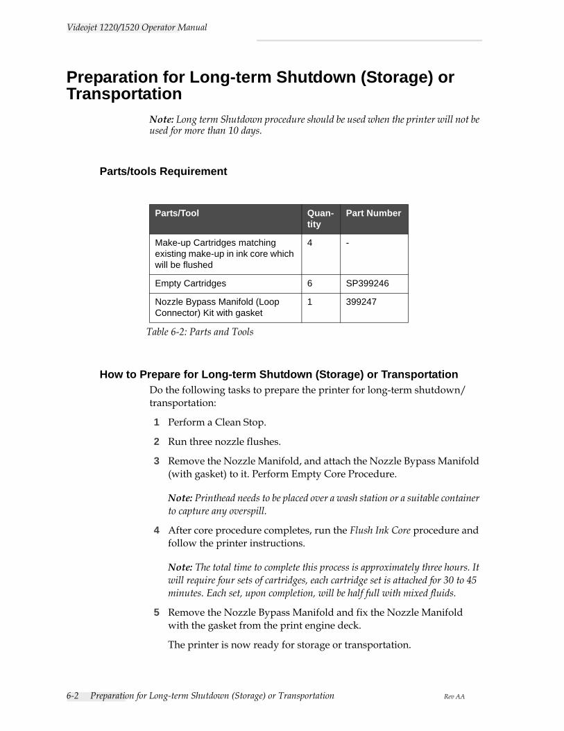
6-2 Preparation for Long-term Shutdown (Storage) or Transportation Rev AA
Videojet 1220/1520 Operator Manual
Preparation for Long-term Shutdown (Storage) or Transportation
Note: Long term Shutdown procedure should be used when the printer will not be used for more than 10 days.
Parts/tools Requirement
How to Prepare for Long-term Shutdown (Storage) or TransportationDo the following tasks to prepare the printer for long-term shutdown/transportation:
1 Perform a Clean Stop.
2 Run three nozzle flushes.
3 Remove the Nozzle Manifold, and attach the Nozzle Bypass Manifold (with gasket) to it. Perform Empty Core Procedure.
Note: Printhead needs to be placed over a wash station or a suitable container to capture any overspill.
4 After core procedure completes, run the Flush Ink Core procedure and follow the printer instructions.
Note: The total time to complete this process is approximately three hours. It will require four sets of cartridges, each cartridge set is attached for 30 to 45 minutes. Each set, upon completion, will be half full with mixed fluids.
5 Remove the Nozzle Bypass Manifold and fix the Nozzle Manifold with the gasket from the print engine deck.
The printer is now ready for storage or transportation.
Parts/Tool Quan-tity
Part Number
Make-up Cartridges matching existing make-up in ink core which will be flushed
4 -
Empty Cartridges 6 SP399246
Nozzle Bypass Manifold (Loop Connector) Kit with gasket
1 399247
Table 6-2: Parts and Tools
Rev AA Preparation for Long-term Shutdown (Storage) or Transportation 6-3
Videojet 1220/1520 Operator Manual
Note: When the ink core has been refilled with the ink removed for storage, do not recalibrate viscosity on re-install as the calibration data has been saved.
Note: While preparing the printer for long term shut down, for Level 3 password, please contact Videojet Technologies Inc. Customer Service Department at 800.843.3610 (United States only), or contact the local Videojet Technologies Inc. representative for more information. Alternatively, you can visit www.videojet.com>Support>Videojet Password Generator.
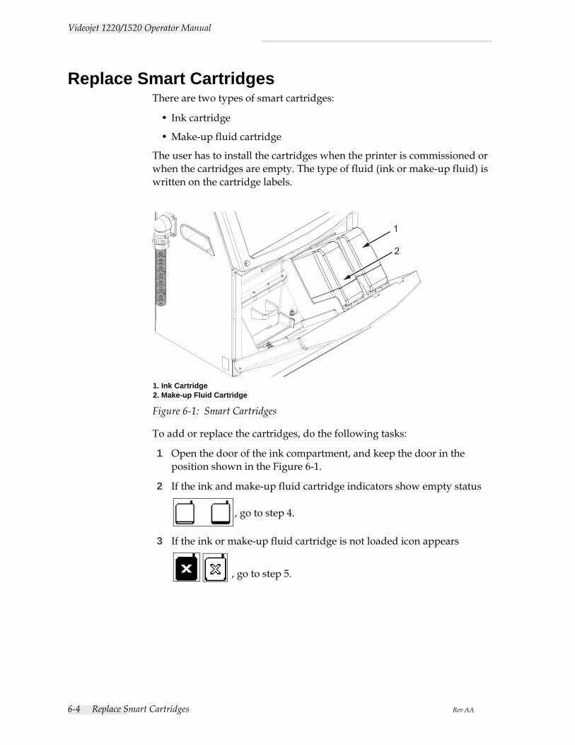
6-4 Replace Smart Cartridges Rev AA
Videojet 1220/1520 Operator Manual
Replace Smart Cartridges There are two types of smart cartridges:
• Ink cartridge
• Make-up fluid cartridge
The user has to install the cartridges when the printer is commissioned or when the cartridges are empty. The type of fluid (ink or make-up fluid) is written on the cartridge labels.
To add or replace the cartridges, do the following tasks:
1 Open the door of the ink compartment, and keep the door in the position shown in the Figure 6-1.
2 If the ink and make-up fluid cartridge indicators show empty status
, go to step 4.
3 If the ink or make-up fluid cartridge is not loaded icon appears
, go to step 5.
1
2
Figure 6-1: Smart Cartridges
1. Ink Cartridge2. Make-up Fluid Cartridge
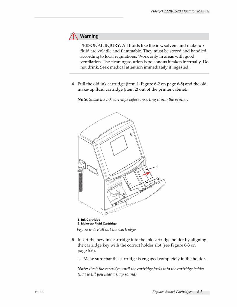
Rev AA Replace Smart Cartridges 6-5
Videojet 1220/1520 Operator Manual
Warning
PERSONAL INJURY. All fluids like the ink, solvent and make-up fluid are volatile and flammable. They must be stored and handled according to local regulations. Work only in areas with good ventilation. The cleaning solution is poisonous if taken internally. Do not drink. Seek medical attention immediately if ingested.
4 Pull the old ink cartridge (item 1, Figure 6-2 on page 6-5) and the old make-up fluid cartridge (item 2) out of the printer cabinet.
Note: Shake the ink cartridge before inserting it into the printer.
5 Insert the new ink cartridge into the ink cartridge holder by aligning the cartridge key with the correct holder slot (see Figure 6-3 on page 6-6).
a. Make sure that the cartridge is engaged completely in the holder.
Note: Push the cartridge until the cartridge locks into the cartridge holder (that is till you hear a snap sound).
Figure 6-2: Pull out the Cartridges
1
2
1. Ink Cartridge2. Make-up Fluid Cartridge
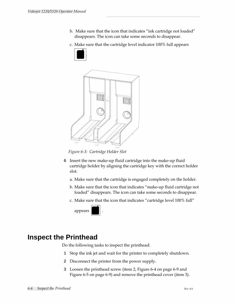
6-6 Inspect the Printhead Rev AA
Videojet 1220/1520 Operator Manual
b. Make sure that the icon that indicates “ink cartridge not loaded” disappears. The icon can take some seconds to disappear.
c. Make sure that the cartridge level indicator 100% full appears
.
6 Insert the new make-up fluid cartridge into the make-up fluid cartridge holder by aligning the cartridge key with the correct holder slot.
a. Make sure that the cartridge is engaged completely on the holder.
b. Make sure that the icon that indicates “make-up fluid cartridge not loaded” disappears. The icon can take some seconds to disappear.
c. Make sure that the icon that indicates “cartridge level 100% full”
appears .
Inspect the PrintheadDo the following tasks to inspect the printhead:
1 Stop the ink jet and wait for the printer to completely shutdown.
2 Disconnect the printer from the power supply.
3 Loosen the printhead screw (item 2, Figure 6-4 on page 6-9 and Figure 6-5 on page 6-9) and remove the printhead cover (item 3).
Figure 6-3: Cartridge Holder Slot
Rev AA Clean the Printhead 6-7
Videojet 1220/1520 Operator Manual
4 Inspect the printhead and the inside of the printhead cover for any ink deposits. Clean if necessary (refer “Clean the Printhead” on page 6-7).
Clean the Printhead
Warning
PERSONAL INJURY. In the event of an ink or solvent spill, leakage from the printer could cause a floor/slip hazard and/or fire hazard (particularly if the equipment is situated over flammable material and/or other equipment). An optional drip tray is available (Part Number 234407). To install, place the drip tray on surface that the printer is to be used. Place the printer in the centre of the drip tray. Ensure that the drip tray is appropriately grounded to avoid static build up.
Warning
VAPOUR HAZARD. Prolonged breathing of cleaning solution vapor can cause drowsiness and/or effects like alcoholic intoxication. Use only in well ventilated, open areas.
Warning
HANDLING CLEANING SOLUTION. The cleaning solution is irritating to the eyes and respiratory system. To prevent personal injury when handling this substance:
Always wear protective rubber gloves and clothing.
Always wear goggles with side-shields or a face mask. It is also advisable to wear safety glasses when carrying out maintenance.
Apply barrier hand cream before handling ink.
If cleaning solution contaminates the skin, rinse off with running water for at least 15 minutes.
6-8 Clean the Printhead Rev AA
Videojet 1220/1520 Operator Manual
Warning
FIRE AND HEALTH HAZARD. The cleaning solution is volatile and flammable. It must be stored and handled in accordance with local regulations.
Do not smoke or use a naked flame in the vicinity of the cleaning solution.
Immediately after use remove any tissues or cloth that are saturated with cleaning solution. Dispose off all such items in accordance with local regulations.
Caution
EQUIPMENT DAMAGE. To prevent the damage to the printer components, use only soft brushes and lint free cloths to clean the printer. Do not use high-pressure air, cotton waste or abrasive materials.
Caution
EQUIPMENT DAMAGE. Make sure that the cleaning solution is compatible with the ink used before you clean the printhead. The failure to follow the caution can damage the printer.
Note: Make sure that the jet is turned off.
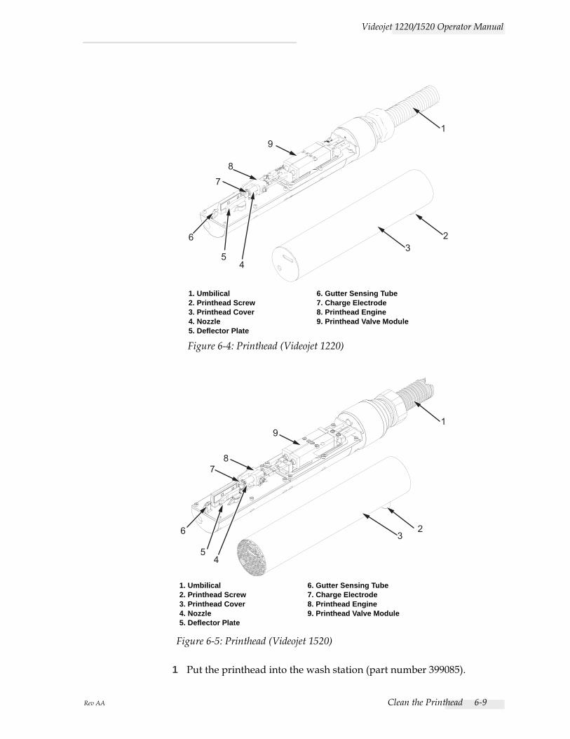
Rev AA Clean the Printhead 6-9
Videojet 1220/1520 Operator Manual
1 Put the printhead into the wash station (part number 399085).
1
23
45
6
78
9
1. Umbilical2. Printhead Screw3. Printhead Cover4. Nozzle5. Deflector Plate
6. Gutter Sensing Tube7. Charge Electrode8. Printhead Engine9. Printhead Valve Module
Figure 6-4: Printhead (Videojet 1220)
1
2 3
4 5
6
7 8
9
1. Umbilical2. Printhead Screw3. Printhead Cover4. Nozzle5. Deflector Plate
6. Gutter Sensing Tube7. Charge Electrode8. Printhead Engine9. Printhead Valve Module
Figure 6-5: Printhead (Videojet 1520)
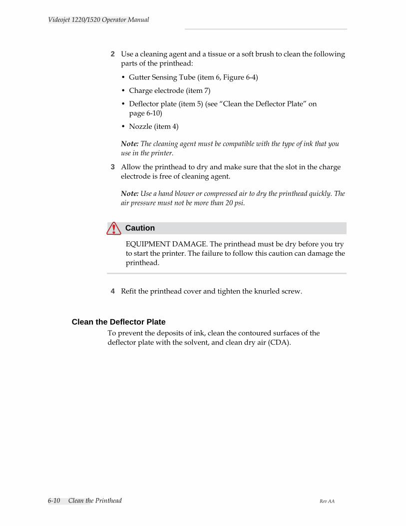
6-10 Clean the Printhead Rev AA
Videojet 1220/1520 Operator Manual
2 Use a cleaning agent and a tissue or a soft brush to clean the following parts of the printhead:
• Gutter Sensing Tube (item 6, Figure 6-4)
• Charge electrode (item 7)
• Deflector plate (item 5) (see “Clean the Deflector Plate” on page 6-10)
• Nozzle (item 4)
Note: The cleaning agent must be compatible with the type of ink that you use in the printer.
3 Allow the printhead to dry and make sure that the slot in the charge electrode is free of cleaning agent.
Note: Use a hand blower or compressed air to dry the printhead quickly. The air pressure must not be more than 20 psi.
Caution
EQUIPMENT DAMAGE. The printhead must be dry before you try to start the printer. The failure to follow this caution can damage the printhead.
4 Refit the printhead cover and tighten the knurled screw.
Clean the Deflector PlateTo prevent the deposits of ink, clean the contoured surfaces of the deflector plate with the solvent, and clean dry air (CDA).
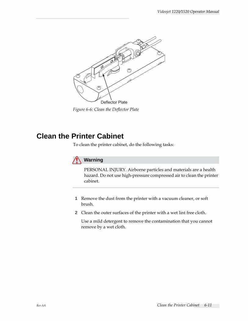
Rev AA Clean the Printer Cabinet 6-11
Videojet 1220/1520 Operator Manual
Clean the Printer CabinetTo clean the printer cabinet, do the following tasks:
Warning
PERSONAL INJURY. Airborne particles and materials are a health hazard. Do not use high-pressure compressed air to clean the printer cabinet.
1 Remove the dust from the printer with a vacuum cleaner, or soft brush.
2 Clean the outer surfaces of the printer with a wet lint free cloth.
Use a mild detergent to remove the contamination that you cannot remove by a wet cloth.
Deflector Plate
Figure 6-6: Clean the Deflector Plate
Rev AA Introduction 7-1
7Troubleshooting
IntroductionThis chapter contains the troubleshooting and fault diagnosis information for the everyday users of the printer.
The service manual has more information on troubleshooting for the service technician and trained personnel.
Warning
LETHAL VOLTAGES. Lethal voltages are present within this equipment when the equipment is connected to the main electrical supply. Only trained and authorised personnel must do the maintenance work. Observe all statutory electrical safety codes and practices. Unless it is necessary to run the printer, disconnect the printer from the main electrical supply before you remove the covers or do any service or repair activity. The failure to follow this warning can cause death or personal injury.
Warning
PERSONAL INJURY. It is possible that in a fault condition the heater can reach 70° C. Do not touch the plate on which heater is installed. The failure to follow this warning can cause the personal injury.
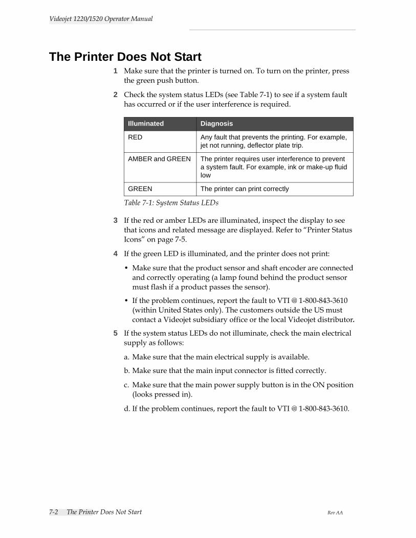
7-2 The Printer Does Not Start Rev AA
Videojet 1220/1520 Operator Manual
The Printer Does Not Start1 Make sure that the printer is turned on. To turn on the printer, press
the green push button.
2 Check the system status LEDs (see Table 7-1) to see if a system fault has occurred or if the user interference is required.
3 If the red or amber LEDs are illuminated, inspect the display to see that icons and related message are displayed. Refer to “Printer Status Icons” on page 7-5.
4 If the green LED is illuminated, and the printer does not print:
• Make sure that the product sensor and shaft encoder are connected and correctly operating (a lamp found behind the product sensor must flash if a product passes the sensor).
• If the problem continues, report the fault to VTI @ 1-800-843-3610 (within United States only). The customers outside the US must contact a Videojet subsidiary office or the local Videojet distributor.
5 If the system status LEDs do not illuminate, check the main electrical supply as follows:
a. Make sure that the main electrical supply is available.
b. Make sure that the main input connector is fitted correctly.
c. Make sure that the main power supply button is in the ON position (looks pressed in).
d. If the problem continues, report the fault to VTI @ 1-800-843-3610.
Illuminated Diagnosis
RED Any fault that prevents the printing. For example, jet not running, deflector plate trip.
AMBER and GREEN The printer requires user interference to prevent a system fault. For example, ink or make-up fluid low
GREEN The printer can print correctly
Table 7-1: System Status LEDs
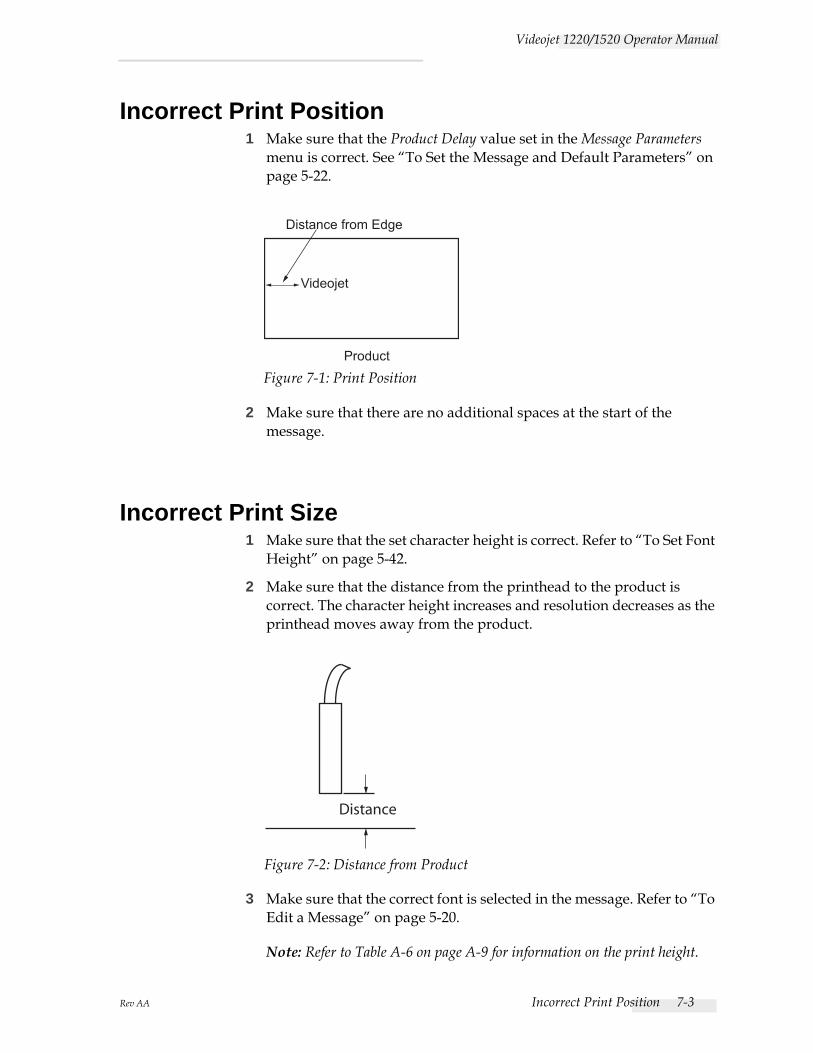
Rev AA Incorrect Print Position 7-3
Videojet 1220/1520 Operator Manual
Incorrect Print Position1 Make sure that the Product Delay value set in the Message Parameters
menu is correct. See “To Set the Message and Default Parameters” on page 5-22.
2 Make sure that there are no additional spaces at the start of the message.
Incorrect Print Size1 Make sure that the set character height is correct. Refer to “To Set Font
Height” on page 5-42.
2 Make sure that the distance from the printhead to the product is correct. The character height increases and resolution decreases as the printhead moves away from the product.
3 Make sure that the correct font is selected in the message. Refer to “To Edit a Message” on page 5-20.
Note: Refer to Table A-6 on page A-9 for information on the print height.
Product
Distance from Edge
Videojet
Figure 7-1: Print Position
Distance
Figure 7-2: Distance from Product
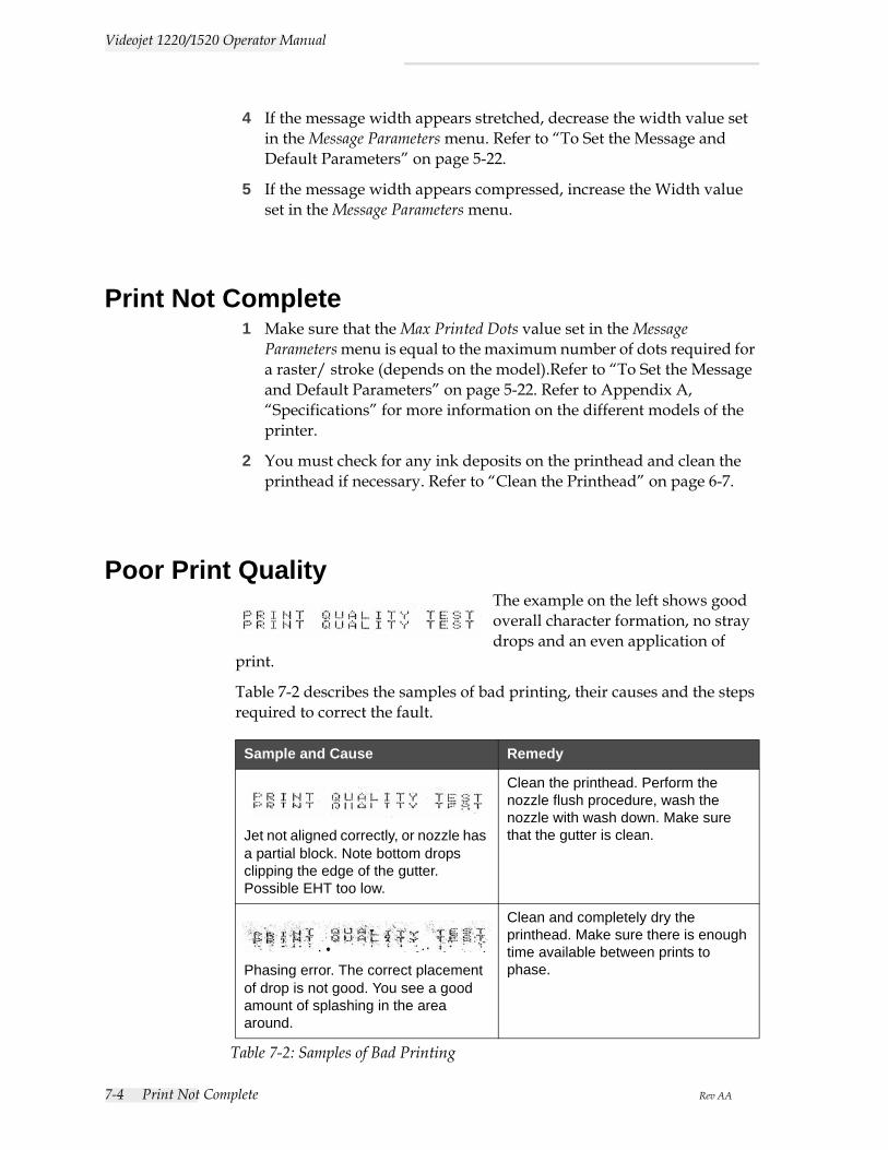
7-4 Print Not Complete Rev AA
Videojet 1220/1520 Operator Manual
4 If the message width appears stretched, decrease the width value set in the Message Parameters menu. Refer to “To Set the Message and Default Parameters” on page 5-22.
5 If the message width appears compressed, increase the Width value set in the Message Parameters menu.
Print Not Complete1 Make sure that the Max Printed Dots value set in the Message
Parameters menu is equal to the maximum number of dots required for a raster/ stroke (depends on the model).Refer to “To Set the Message and Default Parameters” on page 5-22. Refer to Appendix A, “Specifications” for more information on the different models of the printer.
2 You must check for any ink deposits on the printhead and clean the printhead if necessary. Refer to “Clean the Printhead” on page 6-7.
Poor Print QualityThe example on the left shows good overall character formation, no stray drops and an even application of
print.
Table 7-2 describes the samples of bad printing, their causes and the steps required to correct the fault.
Sample and Cause Remedy
Jet not aligned correctly, or nozzle has a partial block. Note bottom drops clipping the edge of the gutter. Possible EHT too low.
Clean the printhead. Perform the nozzle flush procedure, wash the nozzle with wash down. Make sure that the gutter is clean.
Phasing error. The correct placement of drop is not good. You see a good amount of splashing in the area around.
Clean and completely dry the printhead. Make sure there is enough time available between prints to phase.
Table 7-2: Samples of Bad Printing

Rev AA Printer Status Icons 7-5
Videojet 1220/1520 Operator Manual
Printer Status IconsThe printer status icons are divided into three groups:
• The indicator icons. The indicator icons show the status of the ink jet.
Incorrect modulation, too many satellites, charging process not correct.
Backflush nozzle and check for correct breakup.
Pressure too high, drops not deflected correctly, drops “run in” to one another, small print.
Check for jet alignment. Refer to the service manual for more information.
Pressure too low, the drops are over-deflected or incorrectly positioned. Possible loss of most deflected drops.
Check for jet alignment. Refer to the service manual for more information.
Printhead too far from the substrate. The drops are affected by air currents and are spaced too far apart vertically.
Decrease the distance from the substrate, or select a more correct font.
The Printhead slot not vertical to the substrate travel.
The face of the of the printhead must be at 90 degrees angle to the surface of the substrate and the slot must be vertical to the substrate movement. Refer to the figure below.
Sample and Cause Remedy
Table 7-2: Samples of Bad Printing (Continued)
View A View A
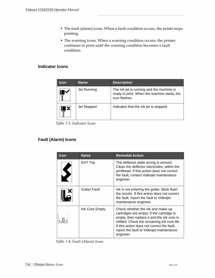
7-6 Printer Status Icons Rev AA
Videojet 1220/1520 Operator Manual
• The fault (alarm) icons. When a fault condition occurs, the prints stops printing.
• The warning icons. When a warning condition occurs, the printer continues to print until the warning condition becomes a fault condition.
Indicator Icons
Fault (Alarm) Icons
Icon Name Description
Jet Running The ink jet is running and the machine is ready to print. When the machine starts, the icon flashes.
Jet Stopped Indicates that the ink jet is stopped.
Table 7-3: Indicator Icons
Icon Name Remedial Action
EHT Trip The deflector plate arcing is sensed. Clean the deflector electrodes, within the printhead. If this action does not correct the fault, contact Videojet maintenance engineer.
Gutter Fault Ink is not entering the gutter. Back flush the nozzle. If this action does not correct the fault, report the fault to Videojet maintenance engineer.
Ink Core Empty Check whether the ink and make-up cartridges are empty. If the cartridge is empty, then replace it and the ink core is refilled. Check the remaining ink core life. If this action does not correct the fault, report the fault to Videojet maintenance engineer.
Table 7-4: Fault (Alarm) Icons
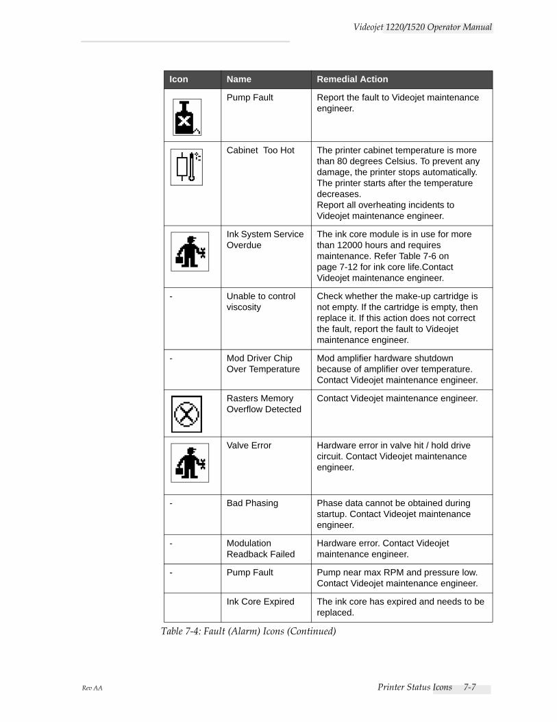
Rev AA Printer Status Icons 7-7
Videojet 1220/1520 Operator Manual
Pump Fault Report the fault to Videojet maintenance engineer.
Cabinet Too Hot The printer cabinet temperature is more than 80 degrees Celsius. To prevent any damage, the printer stops automatically. The printer starts after the temperature decreases. Report all overheating incidents to Videojet maintenance engineer.
Ink System Service Overdue
The ink core module is in use for more than 12000 hours and requires maintenance. Refer Table 7-6 on page 7-12 for ink core life.Contact Videojet maintenance engineer.
- Unable to control viscosity
Check whether the make-up cartridge is not empty. If the cartridge is empty, then replace it. If this action does not correct the fault, report the fault to Videojet maintenance engineer.
- Mod Driver Chip Over Temperature
Mod amplifier hardware shutdown because of amplifier over temperature. Contact Videojet maintenance engineer.
Rasters Memory Overflow Detected
Contact Videojet maintenance engineer.
Valve Error Hardware error in valve hit / hold drive circuit. Contact Videojet maintenance engineer.
- Bad Phasing Phase data cannot be obtained during startup. Contact Videojet maintenance engineer.
- Modulation Readback Failed
Hardware error. Contact Videojet maintenance engineer.
- Pump Fault Pump near max RPM and pressure low. Contact Videojet maintenance engineer.
Ink Core Expired The ink core has expired and needs to be replaced.
Icon Name Remedial Action
Table 7-4: Fault (Alarm) Icons (Continued)
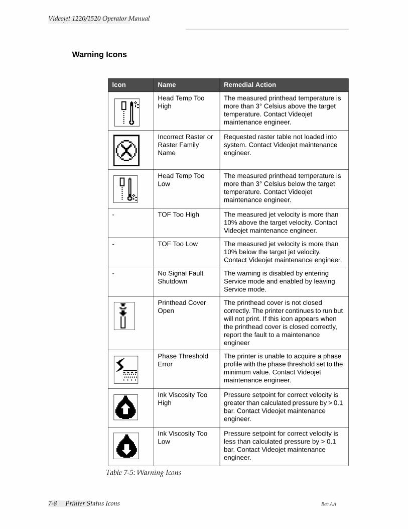
7-8 Printer Status Icons Rev AA
Videojet 1220/1520 Operator Manual
Warning Icons
Icon Name Remedial Action
Head Temp Too High
The measured printhead temperature is more than 3° Celsius above the target temperature. Contact Videojet maintenance engineer.
Incorrect Raster or Raster Family Name
Requested raster table not loaded into system. Contact Videojet maintenance engineer.
Head Temp Too Low
The measured printhead temperature is more than 3° Celsius below the target temperature. Contact Videojet maintenance engineer.
- TOF Too High The measured jet velocity is more than 10% above the target velocity. Contact Videojet maintenance engineer.
- TOF Too Low The measured jet velocity is more than 10% below the target jet velocity. Contact Videojet maintenance engineer.
- No Signal Fault Shutdown
The warning is disabled by entering Service mode and enabled by leaving Service mode.
Printhead Cover Open
The printhead cover is not closed correctly. The printer continues to run but will not print. If this icon appears when the printhead cover is closed correctly, report the fault to a maintenance engineer
Phase Threshold Error
The printer is unable to acquire a phase profile with the phase threshold set to the minimum value. Contact Videojet maintenance engineer.
Ink Viscosity Too High
Pressure setpoint for correct velocity is greater than calculated pressure by > 0.1 bar. Contact Videojet maintenance engineer.
Ink Viscosity Too Low
Pressure setpoint for correct velocity is less than calculated pressure by > 0.1 bar. Contact Videojet maintenance engineer.
Table 7-5: Warning Icons
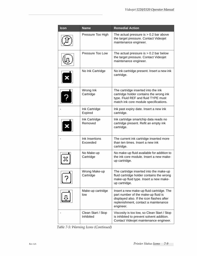
Rev AA Printer Status Icons 7-9
Videojet 1220/1520 Operator Manual
Pressure Too High The actual pressure is > 0.2 bar above the target pressure. Contact Videojet maintenance engineer.
Pressure Too Low The actual pressure is > 0.2 bar below the target pressure. Contact Videojet maintenance engineer.
No Ink Cartridge No ink cartridge present. Insert a new ink cartridge.
Wrong Ink Cartridge
The cartridge inserted into the ink cartridge holder contains the wrong ink type. Fluid REF and fluid TYPE must match ink core module specifications.
- Ink Cartridge Expired
Ink past expiry date. Insert a new ink cartridge.
Ink Cartridge Removed
Ink cartridge smartchip data reads no cartridge present. Refit an empty ink cartridge.
- Ink Insertions Exceeded
The current ink cartridge inserted more than ten times. Insert a new ink cartridge.
No Make-up Cartridge
No make-up fluid available for addition to the ink core module. Insert a new make-up cartridge.
Wrong Make-up Cartridge
The cartridge inserted into the make-up fluid cartridge holder contains the wrong make-up fluid type. Insert a new make-up cartridge.
Make-up cartridge low
Insert a new make-up fluid cartridge. The part number of the make-up fluid is displayed also. If the icon flashes after replenishment, contact a maintenance engineer.
- Clean Start / Stop Inhibited
Viscosity is too low, so Clean Start / Stop is inhibited to prevent solvent addition. Contact Videojet maintenance engineer.
Icon Name Remedial Action
Table 7-5: Warning Icons (Continued)
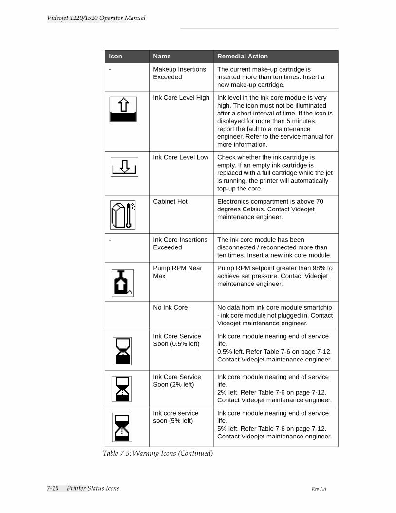
7-10 Printer Status Icons Rev AA
Videojet 1220/1520 Operator Manual
- Makeup Insertions Exceeded
The current make-up cartridge is inserted more than ten times. Insert a new make-up cartridge.
Ink Core Level High Ink level in the ink core module is very high. The icon must not be illuminated after a short interval of time. If the icon is displayed for more than 5 minutes, report the fault to a maintenance engineer. Refer to the service manual for more information.
Ink Core Level Low Check whether the ink cartridge is empty. If an empty ink cartridge is replaced with a full cartridge while the jet is running, the printer will automatically top-up the core.
Cabinet Hot Electronics compartment is above 70 degrees Celsius. Contact Videojet maintenance engineer.
- Ink Core Insertions Exceeded
The ink core module has been disconnected / reconnected more than ten times. Insert a new ink core module.
Pump RPM Near Max
Pump RPM setpoint greater than 98% to achieve set pressure. Contact Videojet maintenance engineer.
No Ink Core No data from ink core module smartchip - ink core module not plugged in. Contact Videojet maintenance engineer.
Ink Core Service Soon (0.5% left)
Ink core module nearing end of service life.0.5% left. Refer Table 7-6 on page 7-12. Contact Videojet maintenance engineer.
Ink Core Service Soon (2% left)
Ink core module nearing end of service life.2% left. Refer Table 7-6 on page 7-12. Contact Videojet maintenance engineer.
Ink core service soon (5% left)
Ink core module nearing end of service life.5% left. Refer Table 7-6 on page 7-12. Contact Videojet maintenance engineer.
Icon Name Remedial Action
Table 7-5: Warning Icons (Continued)
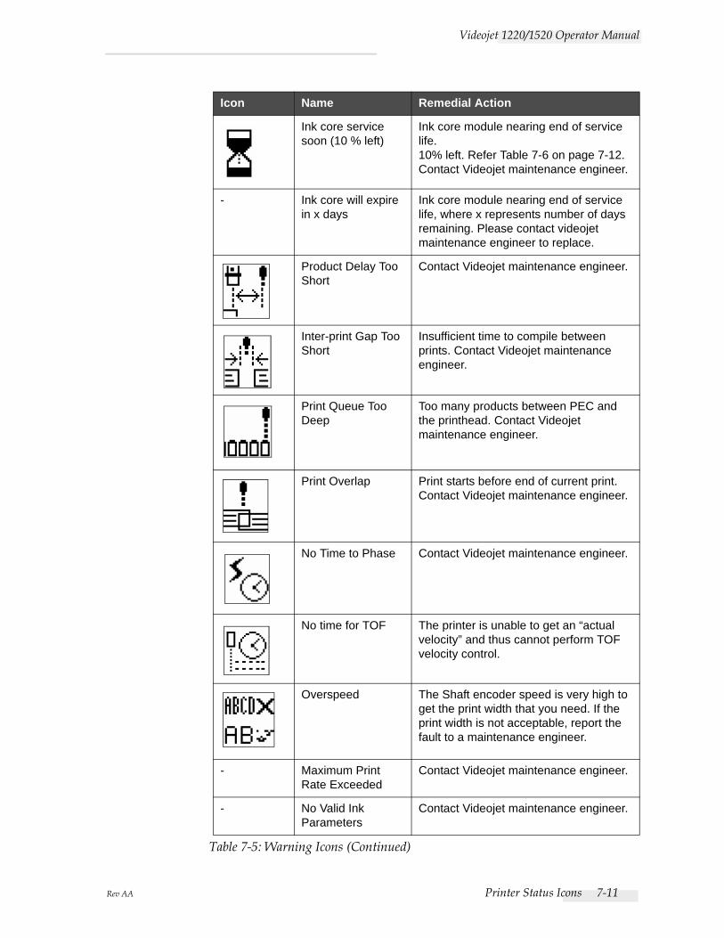
Rev AA Printer Status Icons 7-11
Videojet 1220/1520 Operator Manual
Ink core service soon (10 % left)
Ink core module nearing end of service life.10% left. Refer Table 7-6 on page 7-12. Contact Videojet maintenance engineer.
- Ink core will expire in x days
Ink core module nearing end of service life, where x represents number of days remaining. Please contact videojet maintenance engineer to replace.
Product Delay Too Short
Contact Videojet maintenance engineer.
Inter-print Gap Too Short
Insufficient time to compile between prints. Contact Videojet maintenance engineer.
Print Queue Too Deep
Too many products between PEC and the printhead. Contact Videojet maintenance engineer.
Print Overlap Print starts before end of current print. Contact Videojet maintenance engineer.
No Time to Phase Contact Videojet maintenance engineer.
No time for TOF The printer is unable to get an “actual velocity” and thus cannot perform TOF velocity control.
Overspeed The Shaft encoder speed is very high to get the print width that you need. If the print width is not acceptable, report the fault to a maintenance engineer.
- Maximum Print Rate Exceeded
Contact Videojet maintenance engineer.
- No Valid Ink Parameters
Contact Videojet maintenance engineer.
Icon Name Remedial Action
Table 7-5: Warning Icons (Continued)
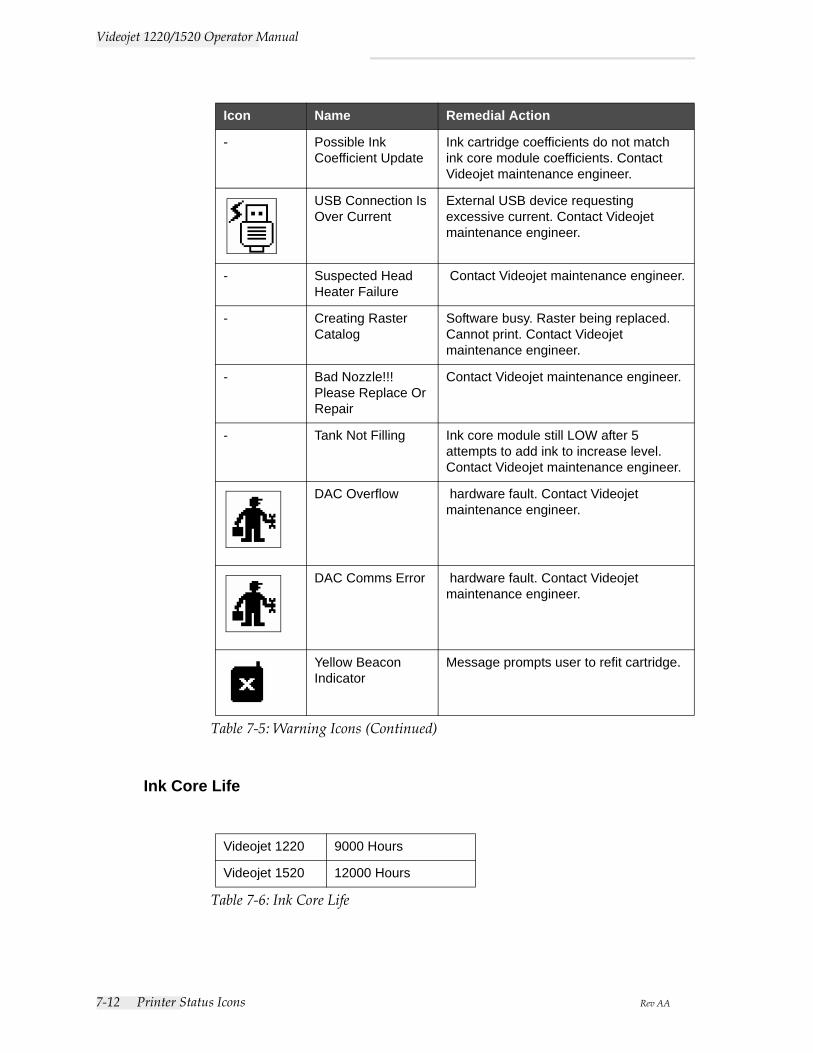
7-12 Printer Status Icons Rev AA
Videojet 1220/1520 Operator Manual
Ink Core Life
- Possible Ink Coefficient Update
Ink cartridge coefficients do not match ink core module coefficients. Contact Videojet maintenance engineer.
USB Connection Is Over Current
External USB device requesting excessive current. Contact Videojet maintenance engineer.
- Suspected Head Heater Failure
Contact Videojet maintenance engineer.
- Creating Raster Catalog
Software busy. Raster being replaced. Cannot print. Contact Videojet maintenance engineer.
- Bad Nozzle!!!Please Replace Or Repair
Contact Videojet maintenance engineer.
- Tank Not Filling Ink core module still LOW after 5 attempts to add ink to increase level. Contact Videojet maintenance engineer.
DAC Overflow hardware fault. Contact Videojet maintenance engineer.
DAC Comms Error hardware fault. Contact Videojet maintenance engineer.
Yellow Beacon Indicator
Message prompts user to refit cartridge.
Videojet 1220 9000 Hours
Videojet 1520 12000 Hours
Table 7-6: Ink Core Life
Icon Name Remedial Action
Table 7-5: Warning Icons (Continued)

Rev AA Printer Status Icons 7-13
Videojet 1220/1520 Operator Manual
Fault MessagesFault messages are displayed at the bottom left of the screen to supplement the printer fault icons. The messages are arranged so that, if more than one fault is found, only the most serious fault message is displayed.
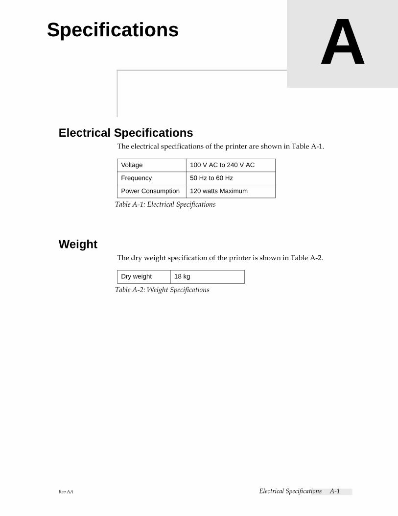
Rev AA Electrical Specifications A-1
ASpecifications
Electrical SpecificationsThe electrical specifications of the printer are shown in Table A-1.
WeightThe dry weight specification of the printer is shown in Table A-2.
Voltage 100 V AC to 240 V AC
Frequency 50 Hz to 60 Hz
Power Consumption 120 watts Maximum
Table A-1: Electrical Specifications
Dry weight 18 kg
Table A-2: Weight Specifications
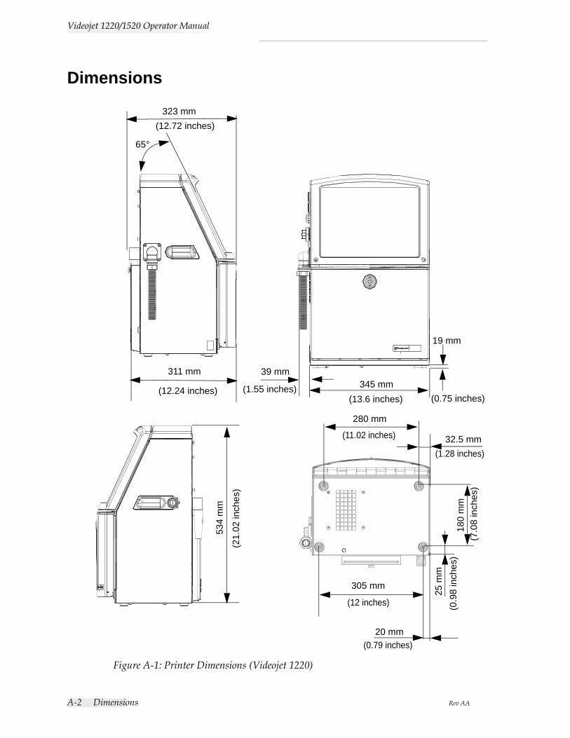
A-2 Dimensions Rev AA
Videojet 1220/1520 Operator Manual
Dimensions
311 mm
65°
39 mm345 mm
19 mm
Figure A-1: Printer Dimensions (Videojet 1220)
(21.
02 in
ches
)
(12.24 inches) (1.55 inches)(13.6 inches) (0.75 inches)
534
mm
280 mm
(11.02 inches) 32.5 mm(1.28 inches)
180
mm
(7.0
8 in
ches
)
305 mm
(12 inches)
20 mm(0.79 inches)
25 m
m(0
.98
inch
es)
323 mm(12.72 inches)
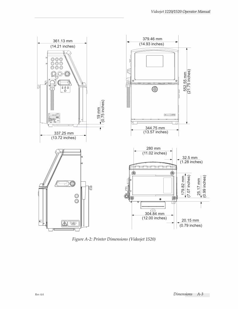
Rev AA Dimensions A-3
Videojet 1220/1520 Operator Manual
337.25 mm
19 m
m(0
.75
inch
es)
(13.72 inches)
361.13 mm(14.21 inches)
552.
55 m
m(2
1.75
inch
es)
379.46 mm(14.93 inches)
344.75 mm(13.57 inches)
280 mm
32.5 mm
304.84 mm
20.15 mm
(1.28 inches)
(11.02 inches)
(12.00 inches)
(0.79 inches)
179.
82 m
m(7
.07
inch
es)
25.1
7 m
m(0
.99
inch
es)
Figure A-2: Printer Dimensions (Videojet 1520)
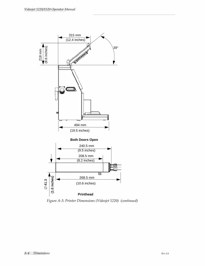
A-4 Dimensions Rev AA
Videojet 1220/1520 Operator Manual
Figure A-3: Printer Dimensions (Videojet 1220) (continued)
240.5 mm
268.5 mm
∅41
.3
315 mm21
8 m
m
39°
494 mm
Both Doors Open
(8.6
inch
es)
(12.4 inches)
(19.5 inches)
(9.5 inches)
(8.2 inches)
(10.6 inches)
(1.6
inch
es)
Printhead
208.5 mm
41.3
(1.6
inch
es)
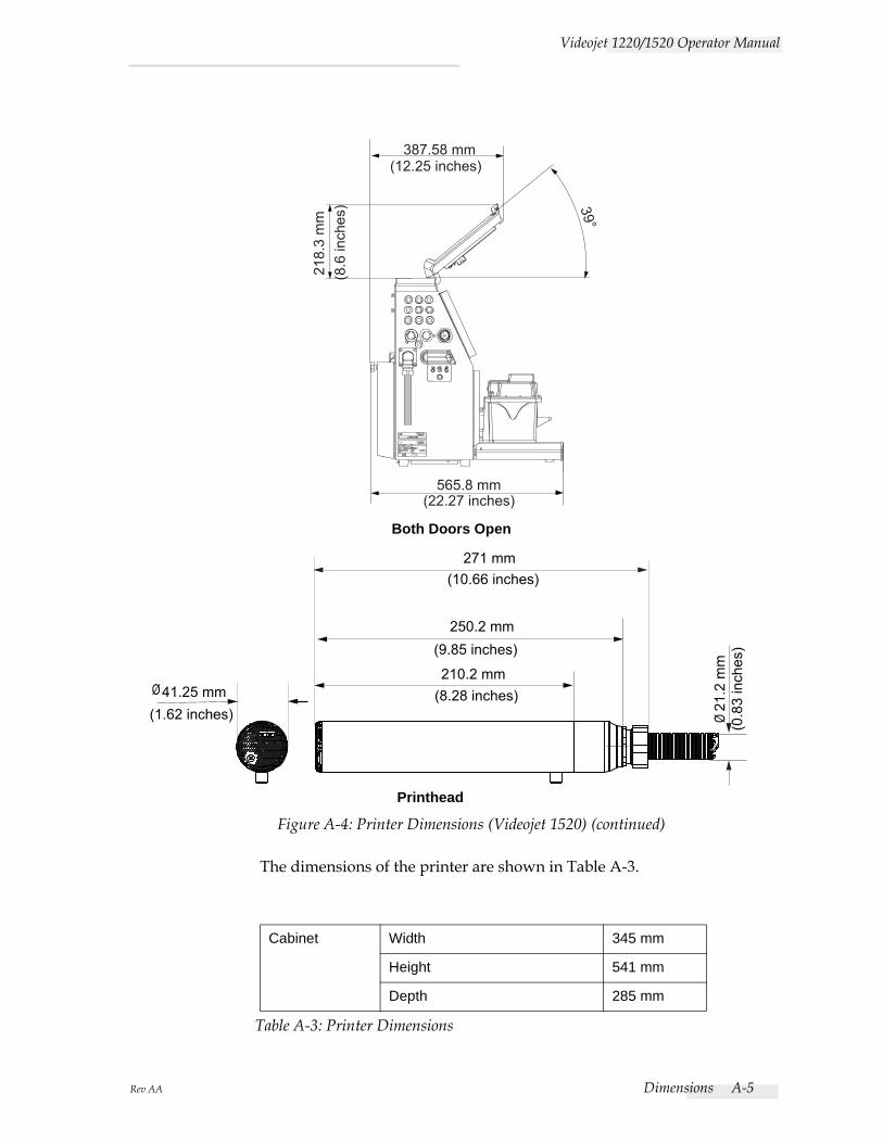
Rev AA Dimensions A-5
Videojet 1220/1520 Operator Manual
The dimensions of the printer are shown in Table A-3.
Cabinet Width 345 mm
Height 541 mm
Depth 285 mm
Table A-3: Printer Dimensions
565.8 mm(22.27 inches)
39°
218.
3 m
m(8
.6 in
ches
)
387.58 mm(12.25 inches)
271 mm
250.2 mm
210.2 mm
(10.66 inches)
(9.85 inches)
41.25 mm(1.62 inches)
(8.28 inches)Ø
21.2
mm
(0.8
3 in
ches
)
Ø
Figure A-4: Printer Dimensions (Videojet 1520) (continued)
Both Doors Open
Printhead
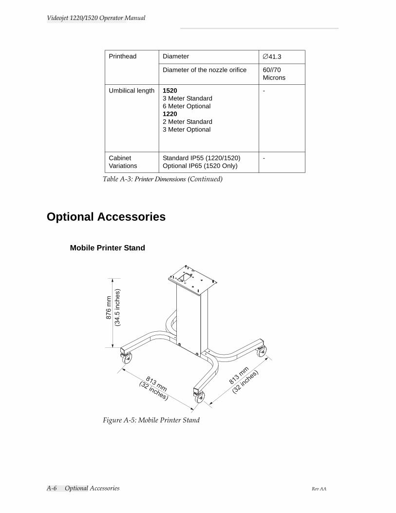
A-6 Optional Accessories Rev AA
Videojet 1220/1520 Operator Manual
Optional Accessories
Mobile Printer Stand
Printhead Diameter ∅41.3
Diameter of the nozzle orifice 60//70 Microns
Umbilical length 15203 Meter Standard6 Meter Optional12202 Meter Standard3 Meter Optional
-
Cabinet Variations
Standard IP55 (1220/1520)Optional IP65 (1520 Only)
-
Table A-3: Printer Dimensions (Continued)
(32 inch
es)81
3 mm
(32 inches)
813 mm
876
mm
(34.
5 in
ches
)
Figure A-5: Mobile Printer Stand
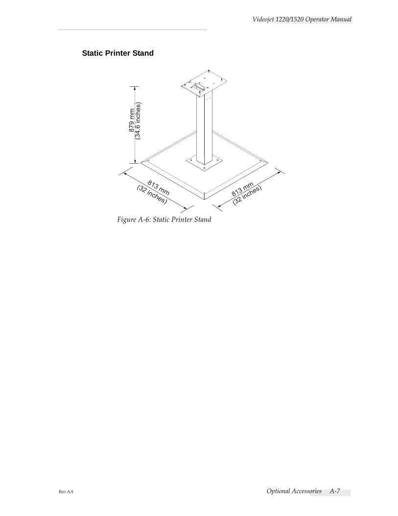
Rev AA Optional Accessories A-7
Videojet 1220/1520 Operator Manual
Static Printer Stand
(34.
6 in
ches
)87
9 m
m
(32 inches)
813 mm
(32 inches)813 mm
Figure A-6: Static Printer Stand
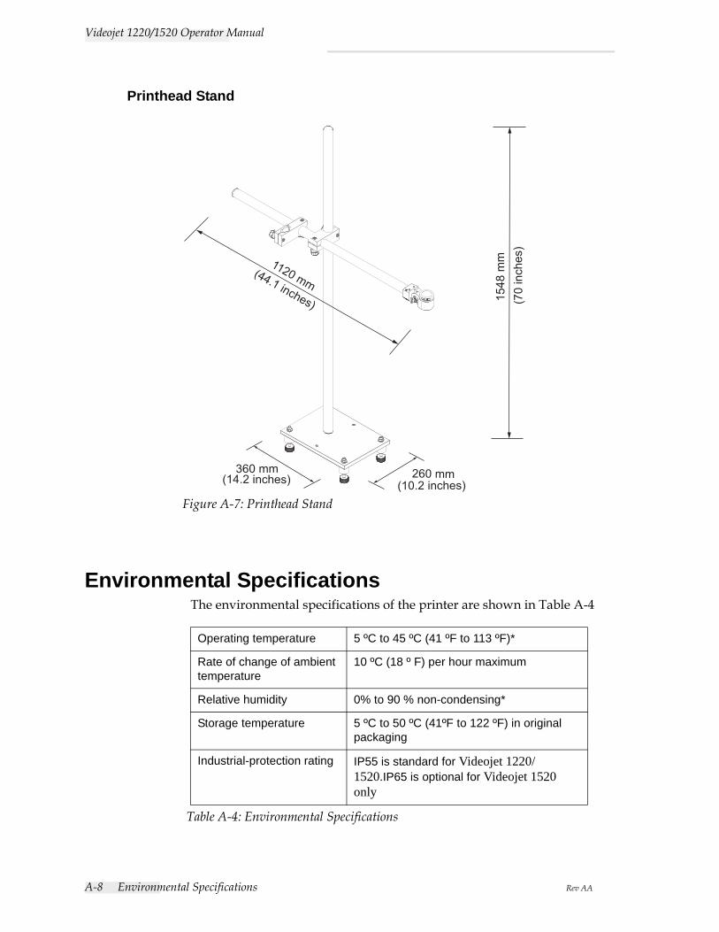
A-8 Environmental Specifications Rev AA
Videojet 1220/1520 Operator Manual
Printhead Stand
Environmental SpecificationsThe environmental specifications of the printer are shown in Table A-4
Operating temperature 5 ºC to 45 ºC (41 ºF to 113 ºF)*
Rate of change of ambient temperature
10 ºC (18 º F) per hour maximum
Relative humidity 0% to 90 % non-condensing*
Storage temperature 5 ºC to 50 ºC (41ºF to 122 ºF) in original packaging
Industrial-protection rating IP55 is standard for Videojet 1220/1520.IP65 is optional for Videojet 1520 only
Table A-4: Environmental Specifications
(70
inch
es)
(44.1 inches)
(14.2 inches) (10.2 inches)260 mm360 mm
1548
mm1120 mm
Figure A-7: Printhead Stand
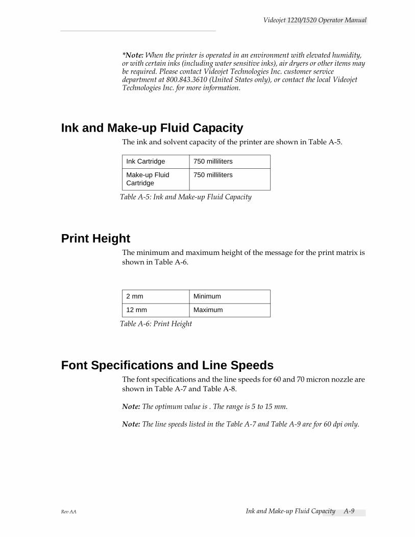
Rev AA Ink and Make-up Fluid Capacity A-9
Videojet 1220/1520 Operator Manual
*Note: When the printer is operated in an environment with elevated humidity, or with certain inks (including water sensitive inks), air dryers or other items may be required. Please contact Videojet Technologies Inc. customer service department at 800.843.3610 (United States only), or contact the local Videojet Technologies Inc. for more information.
Ink and Make-up Fluid CapacityThe ink and solvent capacity of the printer are shown in Table A-5.
Print HeightThe minimum and maximum height of the message for the print matrix is shown in Table A-6.
Font Specifications and Line SpeedsThe font specifications and the line speeds for 60 and 70 micron nozzle are shown in Table A-7 and Table A-8.
Note: The optimum value is . The range is 5 to 15 mm.
Note: The line speeds listed in the Table A-7 and Table A-9 are for 60 dpi only.
Ink Cartridge 750 milliliters
Make-up Fluid Cartridge
750 milliliters
Table A-5: Ink and Make-up Fluid Capacity
2 mm Minimum
12 mm Maximum
Table A-6: Print Height
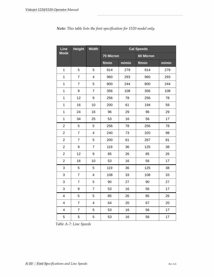
A-10 Font Specifications and Line Speeds Rev AA
Videojet 1220/1520 Operator Manual
Note: This table lists the font specification for 1520 model only.
LineMode
Height Width Cal Speeds
70 Micron 60 Micron
ft/min m/min ft/min m/min
1 5 5 914 279 914 279
1 7 4 960 293 960 293
1 7 5 800 244 800 244
1 9 7 356 108 356 108
1 12 9 256 78 256 78
1 16 10 200 61 194 59
1 24 16 96 29 96 29
1 34 25 53 16 56 17
2 5 5 256 78 256 78
2 7 4 240 73 320 98
2 7 5 200 61 267 81
2 9 7 119 36 125 38
2 12 9 85 26 85 26
2 16 10 53 16 56 17
3 5 5 119 36 125 38
3 7 4 108 33 108 33
3 7 5 90 27 90 27
3 9 7 53 16 56 17
4 5 5 85 26 85 26
4 7 4 64 20 67 20
4 7 5 53 16 56 17
5 5 5 53 16 56 17
Table A-7: Line Speeds
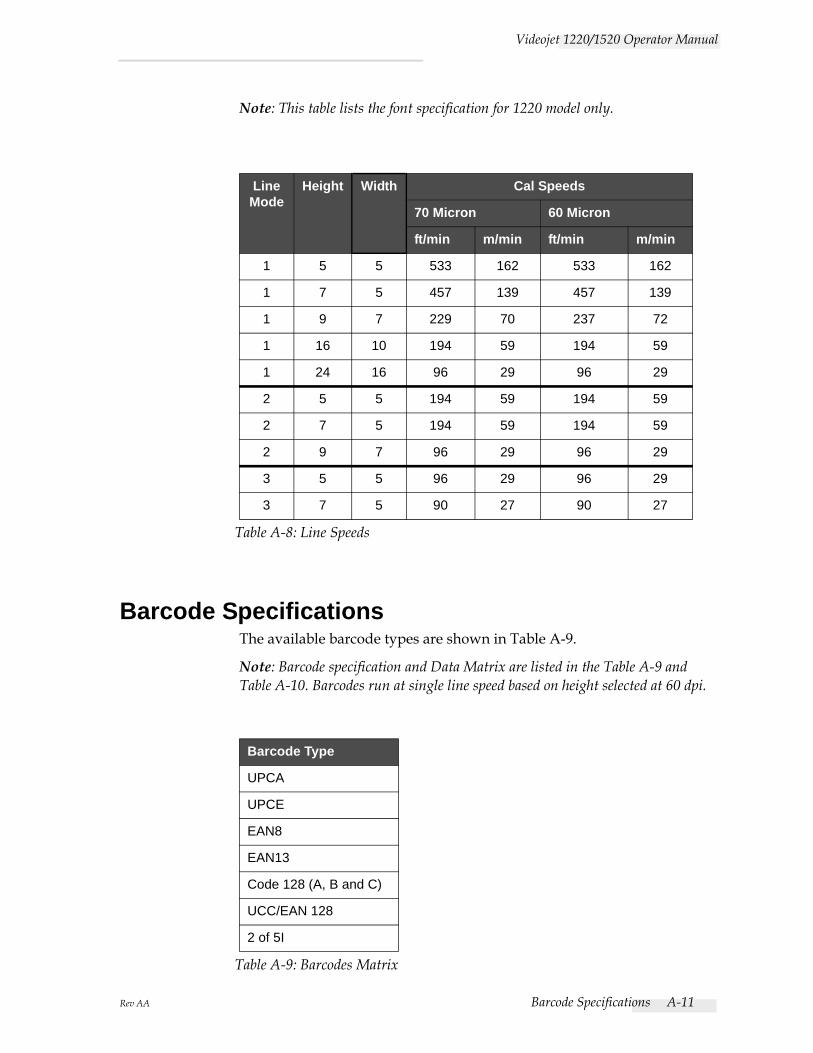
Rev AA Barcode Specifications A-11
Videojet 1220/1520 Operator Manual
Note: This table lists the font specification for 1220 model only.
Barcode SpecificationsThe available barcode types are shown in Table A-9.
Note: Barcode specification and Data Matrix are listed in the Table A-9 and Table A-10. Barcodes run at single line speed based on height selected at 60 dpi.
LineMode
Height Width Cal Speeds
70 Micron 60 Micron
ft/min m/min ft/min m/min
1 5 5 533 162 533 162
1 7 5 457 139 457 139
1 9 7 229 70 237 72
1 16 10 194 59 194 59
1 24 16 96 29 96 29
2 5 5 194 59 194 59
2 7 5 194 59 194 59
2 9 7 96 29 96 29
3 5 5 96 29 96 29
3 7 5 90 27 90 27
Table A-8: Line Speeds
Barcode Type
UPCA
UPCE
EAN8
EAN13
Code 128 (A, B and C)
UCC/EAN 128
2 of 5I
Table A-9: Barcodes Matrix
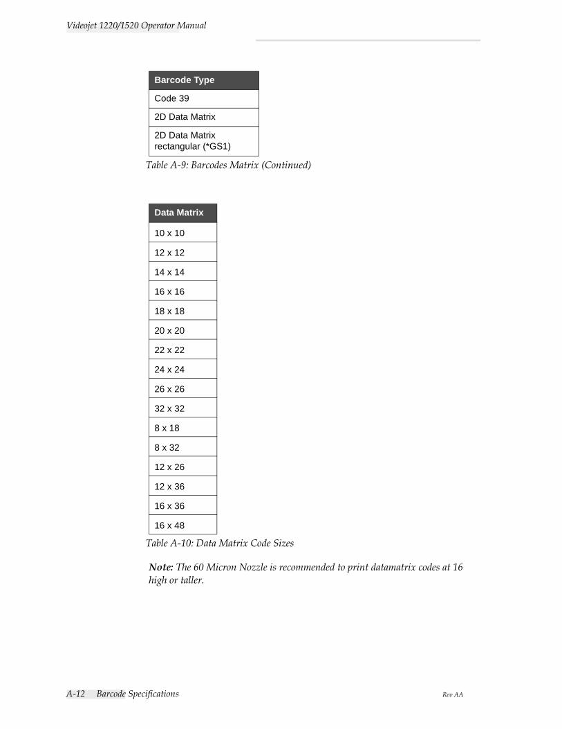
A-12 Barcode Specifications Rev AA
Videojet 1220/1520 Operator Manual
Note: The 60 Micron Nozzle is recommended to print datamatrix codes at 16 high or taller.
Code 39
2D Data Matrix
2D Data Matrix rectangular (*GS1)
Data Matrix
10 x 10
12 x 12
14 x 14
16 x 16
18 x 18
20 x 20
22 x 22
24 x 24
26 x 26
32 x 32
8 x 18
8 x 32
12 x 26
12 x 36
16 x 36
16 x 48
Table A-10: Data Matrix Code Sizes
Barcode Type
Table A-9: Barcodes Matrix (Continued)
Rev AA Glossary-1
Glossary
Character Set The character sets are a combination of number of different language alphabets and special text characters that are programmed in the printer.
ChargeThe electrical charge that is applied to the small drops of ink. The amount of charge applied depends on the destination of the drop on the substrate.
CIJIn the CIJ technology a continuous stream of ink breaks into small ink drops, and these ink drops are deflected to form the characters and images on the substrate
Clean StartClean start is a printer start sequence which removes the splashing of ink and spray during the startup. This startup sequence is used if Clean Stop was used earlier to stop the printing.
Clean StopThe Clean Stop feature provides the required time to remove the ink from the manifold and nozzle before the ink jet stops. This action prevents any deposits of ink on the printhead. A clean printer operates correctly for longer periods of time.
Deflector PlateThe deflector plate creates a high voltage field in the printhead. The high voltage field deflects ink droplets for printing. You can change the voltage in the deflector plate to control the character height.
Gutter The ink not used by the printhead returns through the gutter.
IconA graphical symbol used to indicate a printer state or error condition.
LCDLCD is a thin, flat display device made up of any number of color or monochrome pixels arrayed in front of a light source or reflector.
LEDLED is a semiconductor device that emits visible light when an electric current passes through it.
Message SelectThe method to select the message from an external source and not through the keypad. External source like the Programmable Logic Controller (PLC) or a switch box.
Videojet 1220/1520 Operator Manual
Glossary-2 Rev AA
NozzleInk is supplied to the nozzle assembly and pushed through a small orifice. The nozzle assembly is made to vibrate to break the ink jet into a continuous stream of small drops of ink.
ParametersThe settings which are applied to the message that is printed. For example, message width.
PhasingThe microprocessor control system of the printer monitors the data from the phase detector. This data make sure that there is synchronization between the charging of small ink drops and their break up.
PhotocellA light activated switch that detects the presence of the product to start the printing.
Product DelayThe product delay is the time from when the photocell is activated and the message begins to print.
Quick StartQuick Start is used if the machine is turned off for only less than 30 minutes. This start mode of the printer is used where the nozzle is not flushed.
Quick StopThe Quick Stop is used if the machine will be off for less than 30 minutes. This type of stop mode of the printer is used where the nozzle is full of ink.
RS-232Serial data communications standard which enables the communication between the printer and other devices.
SatellitesSmall additional drops of ink in the ink stream caused by incorrect modulation settings.
Shaft EncoderA device that senses the changes in the product speed and enables the printer to adjust the print width.
SubstrateThe product surface where the printing occurs.
Videojet 1220/1520 Operator Manual
Rev AA Glossary-3
User FieldsA user field is inserted into a message. The user field is copied into the message during the print operation only, so that the user field includes the new updates. (For example, expiry date).
ValveThe hydraulic component in the printer to control the flow of ink within the printer.
WashdownA cleaning solution which cleans the printhead and removes any additional deposits of ink.
WYSIWYGWYSIWYG is an acronym for What You See Is What You Get, used in computing to describe a system in which content displayed during editing appears very similar to the final output (in this case, characters and images printed on the substrate).


