USER GUIDE NI USB-622x/625x/628x OEM M Series USB-6221/6225/6229/6251/6255/6259/6281/6289 OEM Devices This document provides dimensions, pinouts, and information about the connectors, switch, LEDs, and chassis ground of the National Instruments USB-6221 OEM, USB-6225 OEM, USB-6229 OEM, USB-6251 OEM, USB-6255 OEM, USB-6259 OEM, USB-6281 OEM, and USB-6289 OEM devices. It also explains how to modify the USB device name in Microsoft Windows. Caution There are no product safety, electromagnetic compatibility (EMC), or CE marking compliance claims made for the USB-622x/625x/628x OEM devices. Conformity to any and all compliance requirements rests with the end product supplier. Caution (USB-628x Devices) Exercise caution when placing USB-628x OEM devices inside an enclosure. Auxiliary cooling may be necessary to keep the device under the maximum ambient temperature rating of 45 °C, as specified in the NI 628x Specifications. Figure 1 shows the USB-6221/6251/6281 OEM and USB-6225/6229/6255/6259/6289 OEM devices. Figure 1. USB-622x/625x/628x OEM Devices USB-6221/6251/6281 USB-6225/6229/6255/6259/6289
Transcript
USER GUIDE
NI USB-622x/625x/628x OEMM Series USB-6221/6225/6229/6251/6255/6259/6281/6289 OEM Devices
This document provides dimensions, pinouts, and information about the connectors, switch, LEDs, and chassis ground of the National Instruments USB-6221 OEM, USB-6225 OEM, USB-6229 OEM, USB-6251 OEM, USB-6255 OEM, USB-6259 OEM, USB-6281 OEM, and USB-6289 OEM devices. It also explains how to modify the USB device name in Microsoft Windows.
Caution There are no product safety, electromagnetic compatibility (EMC), or CE marking compliance claims made for the USB-622x/625x/628x OEM devices. Conformity to any and all compliance requirements rests with the end product supplier.
Caution (USB-628x Devices) Exercise caution when placing USB-628x OEM devices inside an enclosure. Auxiliary cooling may be necessary to keep the device under the maximum ambient temperature rating of 45 °C, as specified in the NI 628x Specifications.
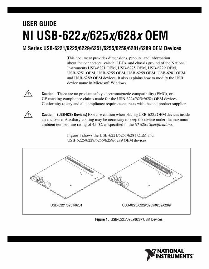
Figure 1 shows the USB-6221/6251/6281 OEM and USB-6225/6229/6255/6259/6289 OEM devices.
Figure 1. USB-622x/625x/628x OEM Devices
USB-6221/6251/6281 USB-6225/6229/6255/6259/6289
NI USB-622x/625x/628x OEM User Guide 2 ni.com
Refer to the NI 622x Specifications document for USB-6221/6225/6229 specifications, the NI 625x Specifications document for USB-6251/6255/6259 specifications, and the NI 628x Specifications document for USB-6281/6289 specifications. Refer to the M Series User Manual for more information about USB-622x/625x/628x devices. You can find all documentation at ni.com/manuals.
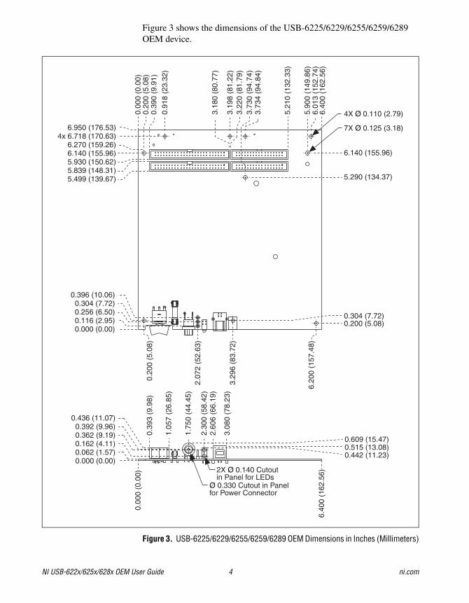
DimensionsFigure 2 shows the dimensions of the USB-6221/6251/6281 OEM device.
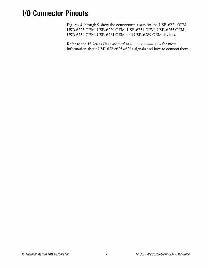
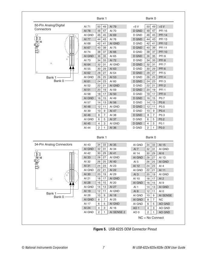
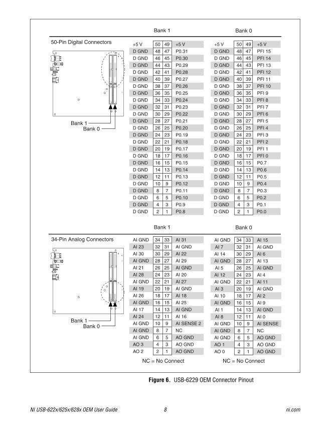
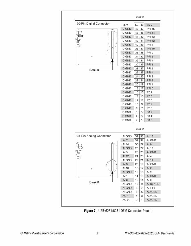
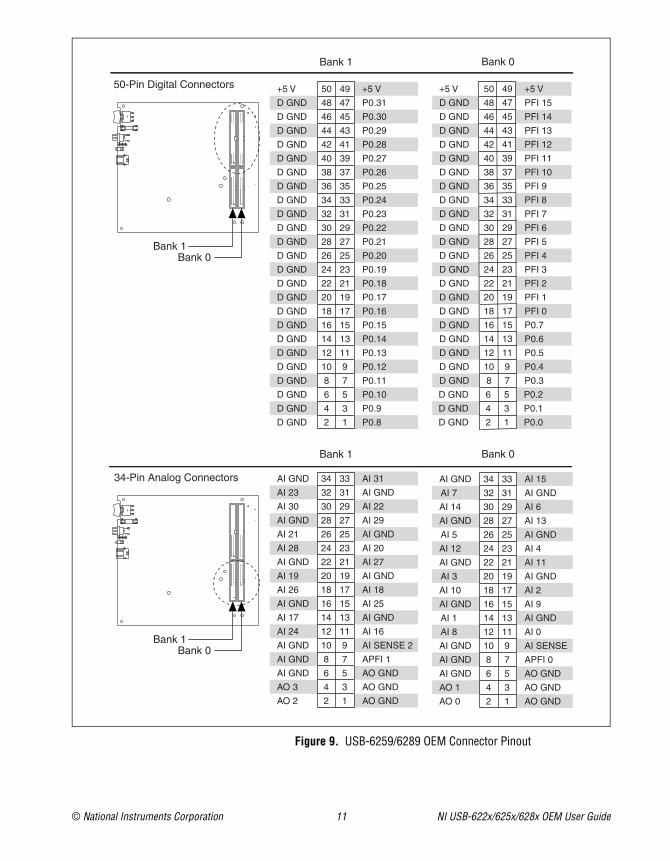
I/O Connector PinoutsFigures 4 through 9 show the connector pinouts for the USB-6221 OEM, USB-6225 OEM, USB-6229 OEM, USB-6251 OEM, USB-6255 OEM, USB-6259 OEM, USB-6281 OEM, and USB-6289 OEM devices.
Refer to the M Series User Manual at ni.com/manuals for more information about USB-622x/625x/628x signals and how to connect them.
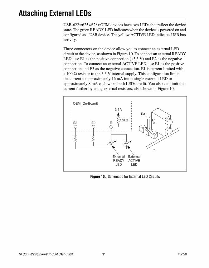
Attaching External LEDsUSB-622x/625x/628x OEM devices have two LEDs that reflect the device state. The green READY LED indicates when the device is powered on and configured as a USB device. The yellow ACTIVE LED indicates USB bus activity.
Three connectors on the device allow you to connect an external LED circuit to the device, as shown in Figure 10. To connect an external READY LED, use E1 as the positive connection (+3.3 V) and E2 as the negative connection. To connect an external ACTIVE LED, use E1 as the positive connection and E3 as the negative connection. E1 is current limited with a 100 Ω resistor to the 3.3 V internal supply. This configuration limits the current to approximately 16 mA into a single external LED or approximately 8 mA each when both LEDs are lit. You also can limit this current further by using external resistors, also shown in Figure 10.
Power SwitchThe power switch on the USB-622x/625x/628x OEM device powers the device on and off. Figure 11 shows the pins on the power switch and circuitry.
Figure 11. Schematic for the Power Switch
Pin 1, VDC In, is connected to VDC through the fuse (reference designator XF1). The VDC is the voltage provided by the power supply through the power connector (reference designator J4/J6/J81) and must be 11–30 VDC, 20 W.
Pin 2, VDC Out, provides power to the circuitry on the device. When the switch is in the On position, the VDC power supply from pin 1 is routed to pin 2.
Pin 3, 100 kΩ to Ground, connects pin 2 to ground through a 100 kΩ resistor when the switch is in the Off position.
1 The power connector is designated as J4 on USB-6225/6255 OEM devices, J6 on USB-6221/6229 OEM devices, and J8 on USB-6251/6259/6281/6289 OEM devices.
J4/J6/J8
VDC Out VDC In
XF
1Switch
123
NC NC
100 kΩSW1
OuterShell
SW1 XF1
FUSE3
Power toDevice
J4/J6/J8
PowerConnector
12
100 kΩ
100 kΩto Ground
NI USB-622x/625x/628x OEM User Guide 14 ni.com
Connecting the USB-622x/625x/628x OEM Device to Your Chassis
The USB-622x/625x/628x OEM device includes several plated mounting holes that are designed for customer grounded connections, as shown in Figure 12.
Caution Do not use the holes labeled A in Figure 12 as mounting holes.
Caution (USB-628x Devices) Exercise caution when placing USB-628x OEM devices inside an enclosure. Auxiliary cooling may be necessary to keep the device under the maximum ambient temperature rating of 45 °C, as specified in the NI 628x Specifications.
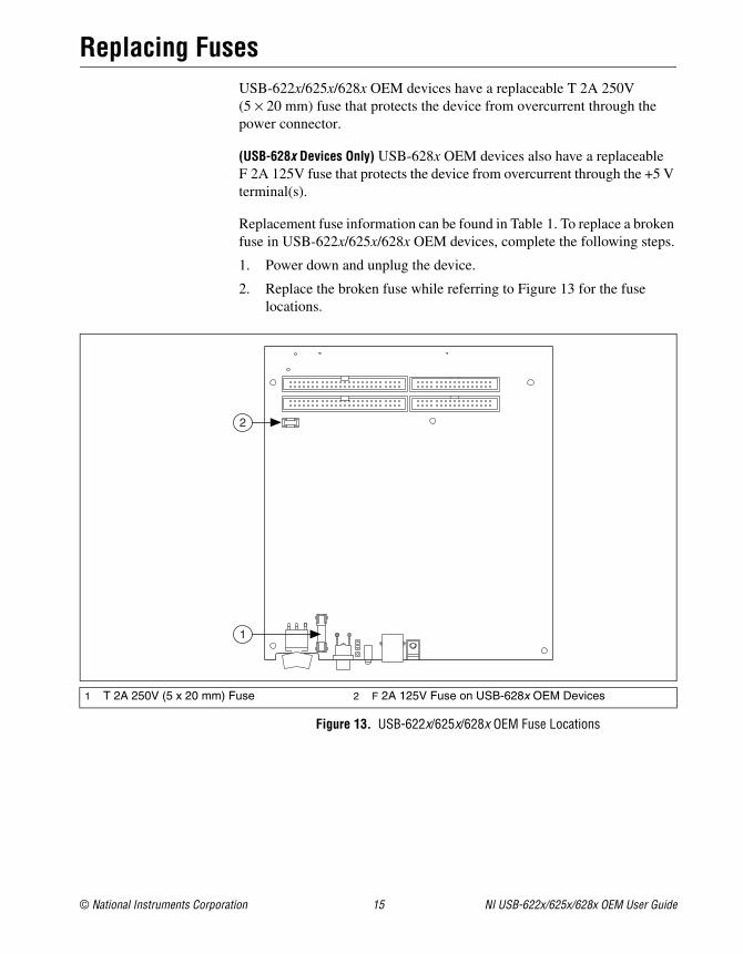
Replacing FusesUSB-622x/625x/628x OEM devices have a replaceable T 2A 250V (5 × 20 mm) fuse that protects the device from overcurrent through the power connector.
(USB-628x Devices Only) USB-628x OEM devices also have a replaceable F 2A 125V fuse that protects the device from overcurrent through the +5 V terminal(s).
Replacement fuse information can be found in Table 1. To replace a broken fuse in USB-622x/625x/628x OEM devices, complete the following steps.
1. Power down and unplug the device.
2. Replace the broken fuse while referring to Figure 13 for the fuse locations.
Figure 13. USB-622x/625x/628x OEM Fuse Locations
1 T 2A 250V (5 x 20 mm) Fuse 2 F 2A 125V Fuse on USB-628x OEM Devices
2
1
NI USB-622x/625x/628x OEM User Guide 16 ni.com
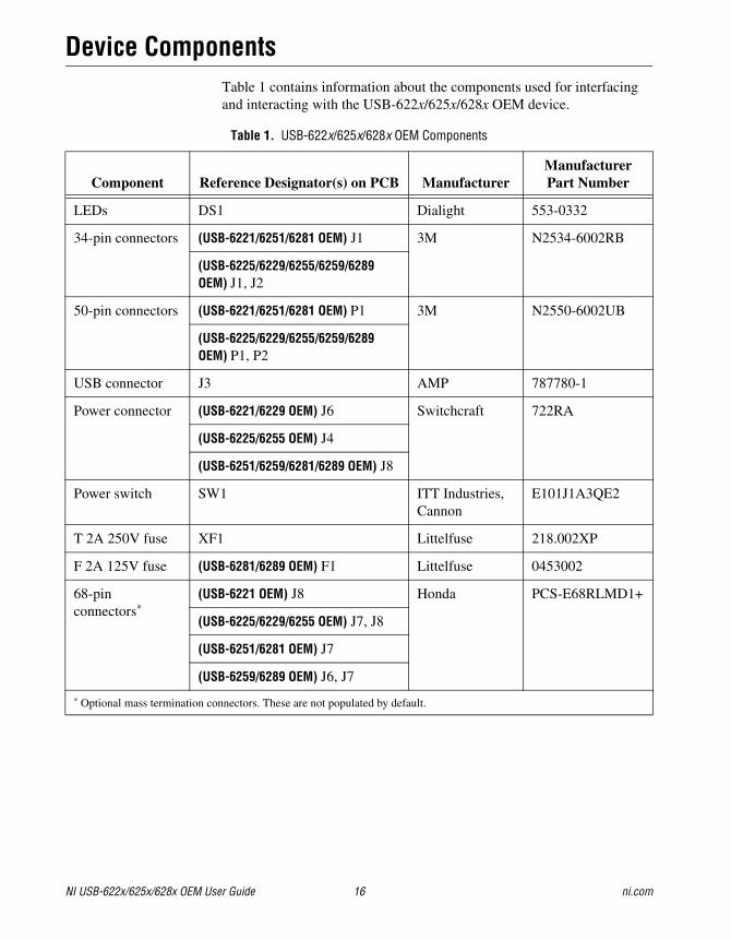
Device ComponentsTable 1 contains information about the components used for interfacing and interacting with the USB-622x/625x/628x OEM device.
Table 1. USB-622x/625x/628x OEM Components
Component Reference Designator(s) on PCB ManufacturerManufacturer Part Number
Modifying the USB Device Name in Microsoft WindowsYou can change how the USB-622x/625x/628x OEM device name appears when users install the device in both the Found New Hardware Wizard that appears when the device is initially installed and in the Windows Device Manager.
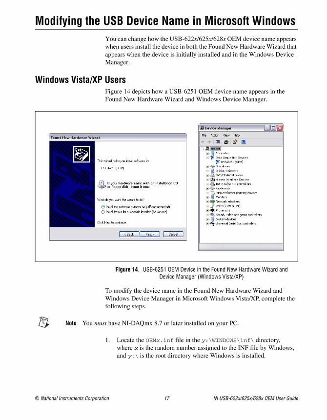
Windows Vista/XP UsersFigure 14 depicts how a USB-6251 OEM device name appears in the Found New Hardware Wizard and Windows Device Manager.
Figure 14. USB-6251 OEM Device in the Found New Hardware Wizard and Device Manager (Windows Vista/XP)
To modify the device name in the Found New Hardware Wizard and Windows Device Manager in Microsoft Windows Vista/XP, complete the following steps.
Note You must have NI-DAQmx 8.7 or later installed on your PC.
1. Locate the OEMx.inf file in the y:\WINDOWS\inf\ directory, where x is the random number assigned to the INF file by Windows, and y:\ is the root directory where Windows is installed.
NI USB-622x/625x/628x OEM User Guide 18 ni.com
Note New security updates to Microsoft Vista and NI-DAQ 8.6 or later create random INF files for NI hardware. Windows assigns random file numbers to all INF files, which causes the user to search through several INF files until the correct file is located.
If you want to revert back, save a copy of this file as OEMx_original.inf in a different location.
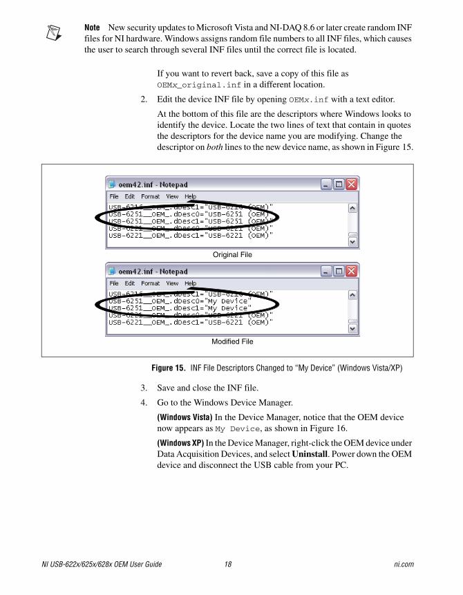
2. Edit the device INF file by opening OEMx.inf with a text editor.
At the bottom of this file are the descriptors where Windows looks to identify the device. Locate the two lines of text that contain in quotes the descriptors for the device name you are modifying. Change the descriptor on both lines to the new device name, as shown in Figure 15.
(Windows Vista) In the Device Manager, notice that the OEM device now appears as My Device, as shown in Figure 16.
(Windows XP) In the Device Manager, right-click the OEM device under Data Acquisition Devices, and select Uninstall. Power down the OEM device and disconnect the USB cable from your PC.
When you reconnect and power on the device, it appears as My Device in the Found New Hardware Wizard and Windows Device Manager, as shown in Figure 16.
Note When the device is initially installed, the Windows alert message may display the following: Found New Hardware: M Series USB 62xx (OEM). This message appears for a few seconds until the custom name appears and the Found New Hardware Wizard is launched. This alert message device name cannot be changed.
Figure 16. “My Device” in the Found New Hardware Wizard and Device Manager (Windows Vista/XP)
Note Modifying the INF file will not change the USB-622x/625x/628x OEM device name in Measurement & Automation Explorer (MAX).
NI USB-622x/625x/628x OEM User Guide 20 ni.com
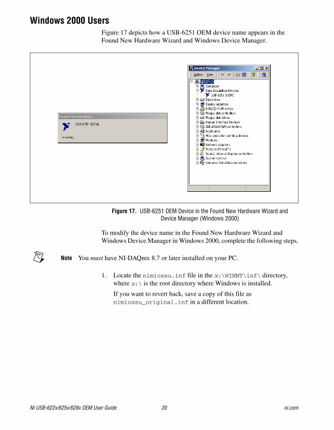
Windows 2000 UsersFigure 17 depicts how a USB-6251 OEM device name appears in the Found New Hardware Wizard and Windows Device Manager.
Figure 17. USB-6251 OEM Device in the Found New Hardware Wizard and Device Manager (Windows 2000)
To modify the device name in the Found New Hardware Wizard and Windows Device Manager in Windows 2000, complete the following steps.
Note You must have NI-DAQmx 8.7 or later installed on your PC.
1. Locate the nimioxsu.inf file in the x:\WINNT\inf\ directory, where x:\ is the root directory where Windows is installed.
If you want to revert back, save a copy of this file as nimioxsu_original.inf in a different location.
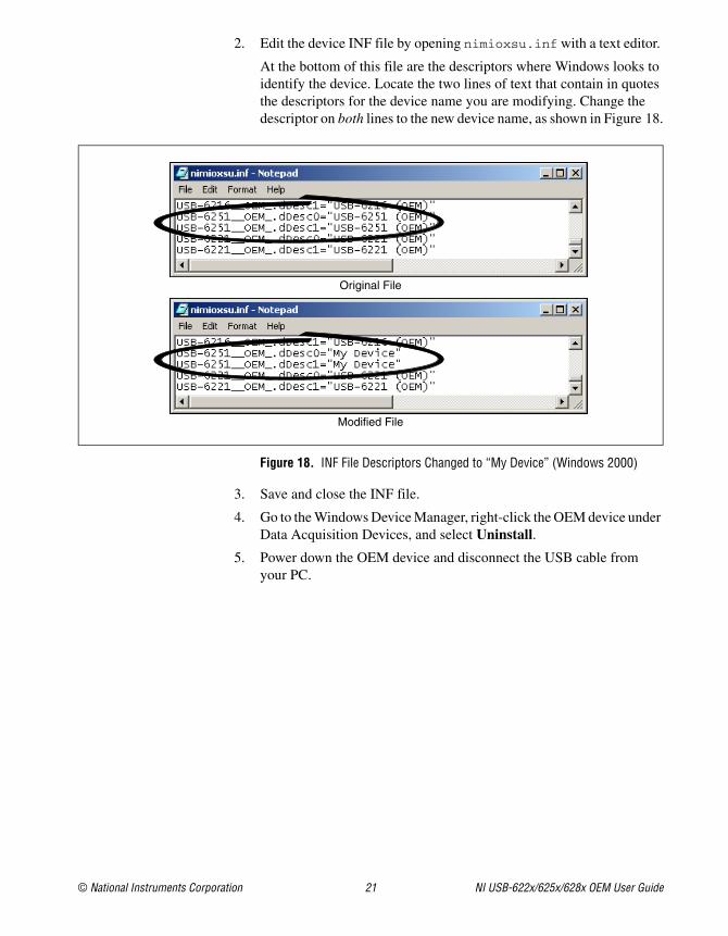
2. Edit the device INF file by opening nimioxsu.inf with a text editor.
At the bottom of this file are the descriptors where Windows looks to identify the device. Locate the two lines of text that contain in quotes the descriptors for the device name you are modifying. Change the descriptor on both lines to the new device name, as shown in Figure 18.
4. Go to the Windows Device Manager, right-click the OEM device under Data Acquisition Devices, and select Uninstall.
5. Power down the OEM device and disconnect the USB cable from your PC.
Original File
Modified File
National Instruments, NI, ni.com, and LabVIEW are trademarks of National Instruments Corporation. Refer to the Terms of Use section on ni.com/legal for more information about National Instruments trademarks. Other product and company names mentioned herein are trademarks or trade names of their respective companies. For patents covering National Instruments products, refer to the appropriate location: Help»Patents in your software, the patents.txt file on your CD, or ni.com/patents.
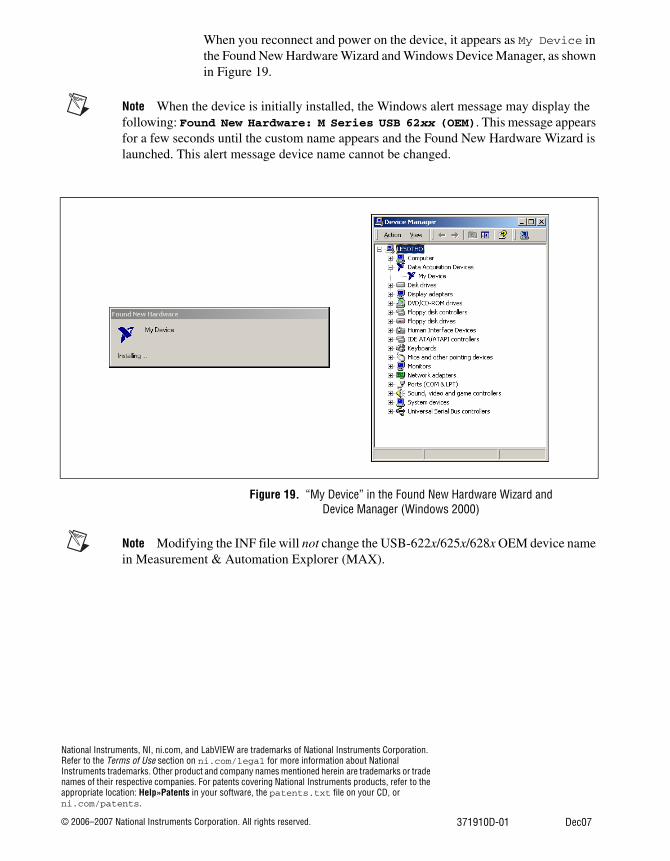
When you reconnect and power on the device, it appears as My Device in the Found New Hardware Wizard and Windows Device Manager, as shown in Figure 19.
Note When the device is initially installed, the Windows alert message may display the following: Found New Hardware: M Series USB 62xx (OEM). This message appears for a few seconds until the custom name appears and the Found New Hardware Wizard is launched. This alert message device name cannot be changed.
Figure 19. “My Device” in the Found New Hardware Wizard and Device Manager (Windows 2000)
Note Modifying the INF file will not change the USB-622x/625x/628x OEM device name in Measurement & Automation Explorer (MAX).


![Finale 2007 - [Untitled1] - Home | Musica Brasilismusicabrasilis.org.br/sites/default/files/partitura/... · 2013-02-01 · B?? b b b # ## b b b b b b b b b b b b Picc Fl 1 e 2 Ob](https://static.documents.pub/doc/80x56/5b737b707f8b9a95348e2e72/finale-2007-untitled1-home-musica-br-2013-02-01-b-b-b-b-b.jpg)


![¿ ² µ4PB B]:w:wBsBcBtBzBò:w4 · = b¥b bnb®bhb·: xb ¡ 0b*b'b b)b bab b b]b.1-b(b b#b b*b¤bjb¤bj. 3db*b bab a ... p/ aî / $¢aîbvb~b n#b1 Ê b-b, Î1\b /v bub 5ÿb b b"b](https://static.documents.pub/doc/80x56/5f1c448ccaed11121b79f5aa/-4pb-bwwbsbcbtbzbw4-bb-bnbbhb-xb-0bbb-bb-bab-b-bb1-bb.jpg)


