138


For further assistanceplease contact us at:
Worldwide Headquarters2195 Keating Cross RoadSaanichton, BCCanada V8M 2A5Tel: 1-250-652-7100Fax: 1-250-652-0411Email: [email protected]
www.pwrm.com
© 2005 Power MeasurementPrinted in CanadaRevision Date: Feb. 1, 200570000-0004-04
Notices Danger
This symbol indicates the presence of dangerous voltage within and outside the product enclosure that may constitute a risk of electric shock, serious injury or death to persons if proper precautions are not followed.
CautionThis symbol alerts the user to the presence of hazards that may cause minor or moderate injury to persons, damage to property or damage to the device itself, if proper precautions are not followed.
NoteThis symbol directs the user’s attention to important installation, operating and maintenance instructions.
Installation ConsiderationsInstallation and maintenance of the 3720 ACM meter should only be performed by qualified, competent personnel that have appropriate training and experience with high voltage and current devices. The meter must be installed in accordance with all Local and National Electrical Codes.
DANGER
Failure to observe the following instructions may result in severe injury or death.
During normal operation of the 3720 ACM meter, hazardous voltages are present on its terminal strips, and throughout the connected potential transformer (PT), current transformer (CT), digital (status) input, control power and external I/O circuits. PT and CT secondary circuits are capable of generating lethal voltages and currents with their primary circuit energized. Follow standard safety precautions while performing any installation or service work (i.e. removing PT fuses, shorting CT secondaries, etc).
The terminal strips on the meter base should not be user-accessible after installation.
Do not use digital output devices for primary protection functions. These include applications where the devices perform energy limiting functions or provide protection of people from injury. Do not use the 3720 ACM in situations where failure of the devices can cause injury or death, or cause sufficient energy to be released that can start a fire. The meter can be used for secondary protection functions.
Do not HIPOT/Dielectric test the digital (status) inputs, digital outputs, or communications terminals. Refer to the label on the 3720 ACM meter for the maximum voltage level the device can withstand.

CAUTION
Observe the following instructions, or permanent damage to the meter may occur.
The 3720 ACM meter offers a range of hardware options that affect input ratings. The 3720 ACM meter’s serial number label lists all equipped options. Applying current levels incompatible with the current inputs will permanently damage the meter. This document provides installation instructions applicable to each hardware option.
The 3720 ACM meter’s chassis ground must be properly connected to the switchgear earth ground for the noise and surge protection circuitry to function correctly. Failure to do so will void the warranty.
Terminal screw torque: Barrier-type (current, voltage, and relay terminal screws: 1.35 Nm (1.00 ft-lbf) max. Captured-wire type (digital inputs/outputs, communications, power supply: 0.90 Nm (0.66 ft.lbf) max.
FCC NoticeThis equipment has been tested and found to comply with the limits for a Class A digital device, pursuant to Part 15 of the FCC Rules. These limits are designed to provide reasonable protection against harmful interference when the equipment is operated in a commercial environment. This equipment generates, uses, and can radiate radio frequency energy and, if not installed and used in accordance with the instruction manual, may cause harmful interference to radio communications. Operation of this equipment in a residential area is likely to cause harmful interference in which case the user will be required to correct the interference at his own expense. The Ringer Equivalence Number (REN) for the 3720 ACM optional internal modem is 0.6. Connection to the 3720 ACM internal modem should be made via an FCC Part 68 compliant telephone cord (not supplied). The 3720 ACM cannot be used on a public coin phone service or party line services.
Network Compatibility Notice for the Internal ModemThe internal modem in meters equipped with this option is compatible with the telephone systems of most countries in the world, with the exception of Australia and New Zealand. Use in some countries may require modification of the internal modem’s initialization strings. If problems using the modem on your phone system occur, please contact Power Measurement Technical Services
Standards Compliance
CSA certifiedLR 57329UL3111-1NRTL/C
ListedIndustrial ControlEquipment1T98

Limitation of LiabilityPower Measurement Ltd. (“Power Measurement”) reserves the right to make changes in the device or its specifications identified in this document without notice. Power Measurement advises customers to obtain the latest version of the device specifications before placing orders to verify that the information being relied upon by the customer is current.
Regardless of whether any remedy set forth herein fails of its essential purpose, except to the extent the following limitation is prohibited by applicable law, Power Measurement shall not, in any event or under any legal claim or theory (whether based on contract, indemnity, warranty, tort (including negligence and strict liability) or otherwise), be liable to the original purchaser or any other person or entity for special, indirect, incidental, punitive, liquidated, special or consequential damages whatsoever with respect to any purchased product, including, without limitation, business interruption, loss of use, profit or revenue, even if Power Measurement has been advised of the possibility of such damages. To the extent that a limitation or exclusion of consequential damages are prohibited by applicable law, then Power Measurement’s liability shall be limited to twice the amount of the relevant purchased product. Not to limit the foregoing, a) Power Measurement shall not be liable for any claim (other than a claim solely for the breach of one of the above Warranties that is made in accordance with the above described procedures) made by the original purchaser, its employees, agents, or contractors for any loss, damage, or expense incurred due to, caused by, or related to any purchased product; and b) the above Warranties are the original purchaser's exclusive remedy and Power Measurement hereby expressly disclaims all other warranties, express or implied, including, without limitation, warranties of non-infringement and the implied warranties of merchantability and fitness for a particular purpose.
These limited Warranties shall not apply to any product that has been subject to alteration, accident, misuse, abuse, neglect or failure to exactly follow Power Measurement's instructions for operation and maintenance. Any technical assistance provided by Power Measurement's personnel or representatives in system design shall be deemed to be a proposal and not a recommendation. The responsibility for determining the feasibility of such proposals rests with the original purchaser and should be tested by the original purchaser. It is the original purchaser’s responsibility to determine the suitability of any product and associated documentation for its purposes. The original purchaser acknowledges that 100% "up" time is not realizable because of possible hardware or software defects. The original purchaser recognizes that such defects and failures may cause inaccuracies or malfunctions. Only the terms expressed in these limited Warranties shall apply and no distributor, corporation or other entity, individual or employee of Power Measurement or any other entity is authorized to amend, modify or extend the Warranties in any way.
The information contained in this document is believed to be accurate at the time of publication, however, Power Measurement assumes no responsibility for any errors which may appear here and reserves the right to make changes without notice.
Power Measurement, ION, ION Enterprise, MeterM@il, WebMeter and “drive energy performance” are either registered trademarks or trademarks of Power Measurement. All other trademarks are property of their respective owners.
Covered by one or more of the following patents:
U.S. Patent No's 6792364, 6792337, 6751562, 6745138, 6737855, 6694270, 6687627, 6671654, 6671635, 6615147, 6611922, 6611773, 6563697, 6493644, 6397155, 6186842, 6185508, 6000034, 5995911, 5828576, 5736847, 5650936, D459259, D458863, D443541, D439535, D435471, D432934, D429655, D429533, D427533.

Power Measurement 3720 ACM Installation and Operation Manual
Wiring diagrams and labels use symbols to denote the following objects:
Fuse
Potential Transformer (PT)
Current Transformer (CT)
Switchgear chassis (Earth) ground
Alternating current
Direct current
3 Three-phase alternating current
Protective conductor termainal
This device has a display timeout feature which automatically turns off the front panel displayafter a programmable timeout period. When the device is shipped, this timeout period is presetto 180 minutes (3 hours). Following a display timeout, you can turn the display back on bypressing any button on the front panel.
DISPLAY TIMEOUT
SYMBOLS

Power Measurement 3720 ACM Installation and Operation Manual
Table of Contents
1 INTRODUCTION
2 INSTALLATION
2.1 Location & Mounting ................................................................................................ 2-1
2.2 General Wiring Considerations ................................................................................ 2-2
2.3 Power Supply Connections ...................................................................................... 2-2
2.4 Chassis Ground Connection .................................................................................... 2-2
2.5 Phase Voltage and Phase Current Input Connections ............................................. 2-32.5.1 Phase Voltage Inputs .............................................................................. 2-32.5.2 Phase Current Inputs ............................................................................... 2-32.5.3 PT & CT Connection ............................................................................... 2-42.5.4 Voltage Reference Connection ................................................................ 2-42.5.5 Waveform Capture Connections .............................................................. 2-52.5.6 I4 Current Input Connections ................................................................... 2-52.5.7 Connection for Three Phase WYE(Star) Systems ................................... 2-62.5.8 Connection for Three Phase Delta Systems ........................................... 2-92.5.9 Connection for Single Phase Systems .................................................. 2-11
2.6 Communications Connections ............................................................................... 2-122.6.1 Introduction ........................................................................................... 2-122.6.2 ISOCOM2 Communications Card .......................................................... 2-122.6.3.a Multiport Communications Card (MPCC) ............................................... 2-142.6.3.b Multiport Communications Card with Ethernet (MPE) ............................ 2-152.6.4 RS-232 Connections .............................................................................. 2-172.6.5 RS-485 Connections .............................................................................. 2-192.6.6 Multiport Connections ............................................................................ 2-23
2.7 Control Relay Connections .................................................................................... 2-242.7.1 Relay Application Precautions ............................................................... 2-252.7.2 Form-C Relays ...................................................................................... 2-252.7.3 Solid State Relays ................................................................................. 2-26
2.8 Status Input Connections ...................................................................................... 2-27
2.9 Auxiliary Voltage Input Connections ...................................................................... 2-28
2.10 Auxiliary Current OutputConnections ..................................................................... 2-29
2.11 Maintenance .......................................................................................................... 2-292.11.1 Battery Replacement ............................................................................. 2-292.11.2 Display Restore ..................................................................................... 2-29
2.12 Field Service Considerations ................................................................................. 2-30
3 GENERAL OPERATION
3.1 Introduction ............................................................................................................. 3-1
3.2 Power Up ................................................................................................................. 3-1
3.3 Display Mode .......................................................................................................... 3-13.3.1 Front Panel Display ................................................................................. 3-13.3.2 Front Panel Buttons ................................................................................ 3-3

Power Measurement 3720 ACM Installation and Operation Manual
Table of Contents
3.4 Field Programming .................................................................................................. 3-63.4.1 Introduction ............................................................................................. 3-63.4.2 Entering Programming Mode ................................................................... 3-63.4.3 Programming Button Functions ............................................................... 3-63.4.4 Entering and Changing the Password ...................................................... 3-63.4.5 Accessing and Modifying Parameters ..................................................... 3-63.4.6 Operating Parameter Descriptions ........................................................... 3-7
3.5 Setting the Volts Scale, Amps Scale, I4 Scale, Volts Mode, and Standard Freq .. 3-20
3.6 Display Format ...................................................................................................... 3-21
3.7 Control Relay Operation ......................................................................................... 3-21
3.8 Status Input Operation .......................................................................................... 3-22
3.9 Auxiliary Voltage Input Operation .......................................................................... 3-23
3.10 Auxiliary Current Output Operation ........................................................................ 3-24
3.11 Daylight Savings Time .......................................................................................... 3-24
4 MEASURED PARAMETERS AND STATUS INFORMATION
4.1 Introduction ............................................................................................................. 4-1
4.2 High-Speed Measurements...................................................................................... 4-2
4.3 Real-Time Measurements ........................................................................................ 4-24.3.1 Base Measurements ............................................................................... 4-24.3.2 Measurement Modes ............................................................................... 4-4
4.4 Energy ..................................................................................................................... 4-74.4.1 Base Measurements ............................................................................... 4-74.4.2 Measurement Modes ............................................................................... 4-74.4.3 Resetting the Energy Counters................................................................ 4-7
4.5 Power Reading Polarities ......................................................................................... 4-8
4.6 Status Information ................................................................................................... 4-94.6.1 Relays, Status Inputs & Setpoints .......................................................... 4-94.6.2 Diagnostics Parameters .......................................................................... 4-9
5 TIME-OF-USE SYSTEM
5.1 Introduction ............................................................................................................. 5-1
5.2 Programming ........................................................................................................... 5-15.2.1 WinTOU Setup ........................................................................................ 5-15.2.2 Calendar .................................................................................................. 5-15.2.3 Profiles .................................................................................................... 5-15.2.4 Tariffs ...................................................................................................... 5-15.2.5 Energy Registers ..................................................................................... 5-15.2.6 Demand Registers ................................................................................... 5-25.2.7 Status Parameters .................................................................................. 5-2
5.3 Access to TOU Data ............................................................................................... 5-25.3.1 Reading TOU Data .................................................................................. 5-25.3.2 Using TOU Data as Trigger Parameters .................................................. 5-25.3.3 Resetting the TOU Registers................................................................... 5-2
5.4 Calculation of Energy Costs .................................................................................... 5-2

Power Measurement 3720 ACM Installation and Operation Manual
Table of Contents
6 SETPOINT SYSTEM
6.1 Introduction ............................................................................................................. 6-1
6.2 Setpoint Types ........................................................................................................ 6-36.2.1 Introduction ............................................................................................. 6-36.2.2 Setpoint Response Times ....................................................................... 6-36.2.3 High-Speed Setpoints .............................................................................. 6-36.2.4 Standard Setpoints .................................................................................. 6-3
6.3 Trigger Parameters .................................................................................................. 6-36.3.1 Introduction ............................................................................................. 6-36.3.2 Over & Under Setpoints with Time Delays .............................................. 6-56.3.3 On/Off & Counter Setpoints .................................................................... 6-76.3.4 Time-Overcurrent Curve .......................................................................... 6-7
6.4 Setpoint Actions ...................................................................................................... 6-86.4.1 Introduction ............................................................................................. 6-86.4.2 Relay Control ........................................................................................... 6-96.4.3 Waveform Capture Triggering .................................................................. 6-96.4.4 Waveform Recorder Triggering .............................................................. 6-106.4.5 Snapshot Log Triggering ........................................................................ 6-106.4.6 Clearing Functions ................................................................................. 6-10
6.5 Programming Setpoints ......................................................................................... 6-11
6.6 Power Outages ...................................................................................................... 6-12
7 WAVEFORM CAPTURE & RECORDING
7.1 Introduction ............................................................................................................. 7-1
7.2 Waveform Capture ................................................................................................... 7-17.2.1 The Importance of Power Quality Monitoring ........................................... 7-17.2.2 Using Captured Data ............................................................................... 7-17.2.3 Triggering from a Setpoint ....................................................................... 7-17.2.4 Triggering Manually via Communications ................................................ 7-2
7.3 Waveform Recording ............................................................................................... 7-37.3.1 Using Recorded Data ............................................................................... 7-37.3.2 Configuring the Recorder ......................................................................... 7-37.3.3 Triggering from a Setpoint ....................................................................... 7-47.3.4 Adjusting the Trigger Point ...................................................................... 7-47.3.5 Triggering Manually via Communications ................................................ 7-6
8 ON-BOARD DATA LOGGING
8.1 Introduction ............................................................................................................. 8-1
8.2 Event Log ................................................................................................................ 8-1
8.3 Minimum / Maximum Logs ...................................................................................... 8-38.3.1 Preset Min/Max Log ................................................................................ 8-38.3.2 Programmable Min/Max Logs .................................................................. 8-48.3.3 Resetting the Min/Max Logs .................................................................... 8-4
8.4 Programmable Snapshot Logs ................................................................................ 8-58.4.1 Introduction ............................................................................................. 8-58.4.2 Memory Allocation ................................................................................... 8-58.4.3 Standard Snapshot Logs ......................................................................... 8-68.4.4 High-Speed Snapshot Log ....................................................................... 8-8
8.5 Access to Logged Data ......................................................................................... 8-10
8.6 Time Stamp Accuracy ........................................................................................... 8-10
Power Measurement 3720 ACM Installation and Operation Manual
Table of Contents
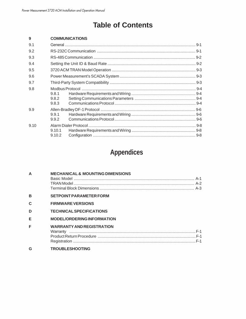
9 COMMUNICATIONS
9.1 General .................................................................................................................... 9-1
9.2 RS-232C Communication ........................................................................................ 9-1
9.3 RS-485 Communication ........................................................................................... 9-2
9.4 Setting the Unit ID & Baud Rate .............................................................................. 9-2
9.5 3720 ACM TRAN Model Operation .......................................................................... 9-3
9.6 Power Measurement's SCADA System ................................................................... 9-3
9.7 Third-Party System Compatibility ............................................................................ 9-3
9.8 Modbus Protocol ..................................................................................................... 9-49.8.1 Hardware Requirements and Wiring ......................................................... 9-49.8.2 Setting Communications Parameters ...................................................... 9-49.8.3 Communications Protocol ........................................................................ 9-4
9.9 Allen-Bradley DF-1 Protocol .................................................................................... 9-69.9.1 Hardware Requirements and Wiring ......................................................... 9-69.9.2 Communications Protocol ........................................................................ 9-6
9.10 Alarm Dialer Protocol ............................................................................................... 9-89.10.1 Hardware Requirements and Wiring ......................................................... 9-89.10.2 Configuration ........................................................................................... 9-8
Appendices
A MECHANICAL & MOUNTING DIMENSIONSBasic Model ........................................................................................................... A-1TRAN Model ........................................................................................................... A-2Terminal Block Dimensions .................................................................................... A-3
B SETPOINT PARAMETER FORM
C FIRMWARE VERSIONS
D TECHNICAL SPECIFICATIONS
E MODEL/ORDERING INFORMATION
F WARRANTY AND REGISTRATIONWarranty ................................................................................................................F-1Product Return Procedure .......................................................................................F-1Registration .............................................................................................................F-1
G TROUBLESHOOTING
Power Measurement 3720 ACM Installation and Operation Manual
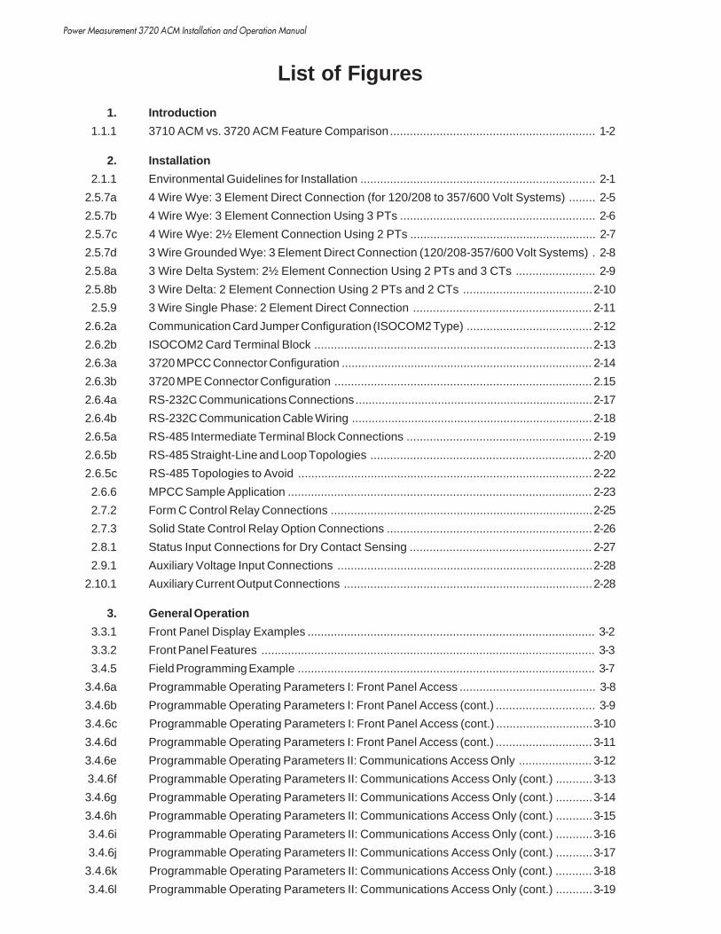
List of Figures
1. Introduction
1.1.1 3710 ACM vs. 3720 ACM Feature Comparison.............................................................. 1-2
2. Installation
2.1.1 Environmental Guidelines for Installation ....................................................................... 2-1
2.5.7a 4 Wire Wye: 3 Element Direct Connection (for 120/208 to 357/600 Volt Systems) ........ 2-5
2.5.7b 4 Wire Wye: 3 Element Connection Using 3 PTs ........................................................... 2-6
2.5.7c 4 Wire Wye: 2½ Element Connection Using 2 PTs ........................................................ 2-7
2.5.7d 3 Wire Grounded Wye: 3 Element Direct Connection (120/208-357/600 Volt Systems) . 2-8
2.5.8a 3 Wire Delta System: 2½ Element Connection Using 2 PTs and 3 CTs ........................ 2-9
2.5.8b 3 Wire Delta: 2 Element Connection Using 2 PTs and 2 CTs .......................................2-10
2.5.9 3 Wire Single Phase: 2 Element Direct Connection ...................................................... 2-11
2.6.2a Communication Card Jumper Configuration (ISOCOM2 Type) ...................................... 2-12
2.6.2b ISOCOM2 Card Terminal Block ....................................................................................2-13
2.6.3a 3720 MPCC Connector Configuration ............................................................................ 2-14
2.6.3b 3720 MPE Connector Configuration .............................................................................. 2.15
2.6.4a RS-232C Communications Connections........................................................................2-17
2.6.4b RS-232C Communication Cable Wiring ......................................................................... 2-18
2.6.5a RS-485 Intermediate Terminal Block Connections ........................................................ 2-19
2.6.5b RS-485 Straight-Line and Loop Topologies ................................................................... 2-20
2.6.5c RS-485 Topologies to Avoid ......................................................................................... 2-22
2.6.6 MPCC Sample Application ............................................................................................ 2-23
2.7.2 Form C Control Relay Connections ...............................................................................2-25
2.7.3 Solid State Control Relay Option Connections .............................................................. 2-26
2.8.1 Status Input Connections for Dry Contact Sensing ....................................................... 2-27
2.9.1 Auxiliary Voltage Input Connections .............................................................................2-28
2.10.1 Auxiliary Current Output Connections ........................................................................... 2-28
3. General Operation
3.3.1 Front Panel Display Examples ....................................................................................... 3-2
3.3.2 Front Panel Features ..................................................................................................... 3-3
3.4.5 Field Programming Example .......................................................................................... 3-7
3.4.6a Programmable Operating Parameters I: Front Panel Access ......................................... 3-8
3.4.6b Programmable Operating Parameters I: Front Panel Access (cont.) .............................. 3-9
3.4.6c Programmable Operating Parameters I: Front Panel Access (cont.) .............................3-10
3.4.6d Programmable Operating Parameters I: Front Panel Access (cont.) ............................. 3-11
3.4.6e Programmable Operating Parameters II: Communications Access Only ...................... 3-12
3.4.6f Programmable Operating Parameters II: Communications Access Only (cont.) ...........3-13
3.4.6g Programmable Operating Parameters II: Communications Access Only (cont.) ...........3-14
3.4.6h Programmable Operating Parameters II: Communications Access Only (cont.) ...........3-15
3.4.6i Programmable Operating Parameters II: Communications Access Only (cont.) ...........3-16
3.4.6j Programmable Operating Parameters II: Communications Access Only (cont.) ...........3-17
3.4.6k Programmable Operating Parameters II: Communications Access Only (cont.) ........... 3-18
3.4.6l Programmable Operating Parameters II: Communications Access Only (cont.) ...........3-19

Power Measurement 3720 ACM Installation and Operation Manual
List of Figures
4. Measured Parameters & Status Information
4.3.1 List of Real-Time Base Measurements & Display Labels ............................................... 4-3
4.3.2a List of Measurement Modes for Real-Time Parameters ................................................. 4-4
4.3.2b Thermal Demand Calculation ......................................................................................... 4-5
4.4.2 List of Measurement Modes for Energy Parameters ...................................................... 4-7
4.5.1 Power Reading Polarities ............................................................................................... 4-8
4.6.1 List of Relay, Status Input & Setpoint Display Labels .................................................... 4-9
4.6.2 Extended Diagnostic Parameters ..................................................................................4-10
5. Time-Of-Use System
5.2.2 WinTOU Setup: Calendar & Profile Setup Example ....................................................... 5-1
5.2.4 WinTOU Setup: Register Setup & Real-Time Display Example ..................................... 5-2
6. Setpoint System
6.1.1 Setpoint Capabilities ...................................................................................................... 6-2
6.3.1 Setpoint Trigger Parameters .......................................................................................... 6-4
6.3.2a Over Setpoint Operation ................................................................................................. 6-5
6.3.2b Under Setpoint Operation ............................................................................................... 6-6
6.3.4 Time-Overcurrent Curve ................................................................................................. 6-7
6.6.1 Setpoint Parameter Form Example ...............................................................................6-11
7. Waveform Capture & Recording
7.2.2a M-SCADA Captured Waveform Screen .......................................................................... 7-2
7.2.2b M-SCADA Harmonic Spectrum Screen .......................................................................... 7-2
7.2.2c M-SCADA Harmonics Table Screen .............................................................................. 7-2
7.3.1 M-SCADA Waveform Recorder Screen .......................................................................... 7-3
7.3.4 Waveform Recorder High-Speed Trigger Point Adjustment ............................................ 7-5
8. On-Board Data Logging
8.2.1 M-SCADA Event Log Screen ......................................................................................... 8-2
8.3.1 M-SCADA Preset Min/Max Log Screen ......................................................................... 8-3
8.3.2 M-SCADA Programmable Min/Max Log Screen ............................................................. 8-4
8.4.1 M-SCADA Standard Snapshot Log Screen .................................................................... 8-5
8.4.2 Snapshot Log Capacity Examples ................................................................................. 8-6
8.4.3a M-SCADA Historical Trending Screen ............................................................................ 8-7
8.4.3b One-Shot vs. Gated Snapshot Logging .......................................................................... 8-7
8.4.4 Snapshot Logging: Modes of Operation ......................................................................... 8-9
9. Communications
9.2.1 Remote Communication Methods .................................................................................. 9-2
9.8.1 Modbus Single and Multi-Drop Connections ................................................................... 9-5
9.9.1 Allen Bradley Single and Multi-Drop Connections .......................................................... 9-7

Power Measurement 3720 ACM Installation and Operation Manual
Introduction 1-1
1 INTRODUCTION
High Performance Power InstrumentationThe 3720 ACM is a microprocessor-based, digital 3-phase“Smart Power Monitor/Meter” designed for use in industrial,commercial, and utility power distribution switchboards andsubstations. The 3720 ACM answers the ever-increasingconcern for ‘clean’, reliable power by integrating the manycritical aspects of power monitoring, analysis, and controlinto one simple and economical instrument. It is a state ofthe art alternative to traditional analog electromechanicalmetering devices, replacing numerous individual transducersand meters, and offering many features previously unavail-able in power instrumentation.
The 3720 ACM offers the high accuracy, reliability, andruggedness of its companion product, the successful3710 ACM, while adding many new measurements andadvanced features (see Figure 1.1.1). The 3720 ACM alsomatches the 3710 ACM in its mounting dimensions, installa-tion requirements, and in its straightforward and flexible userinterface.
The unit is based around a 13.5 MHz, 16 bit microcontrollerchip. This provides very high computational throughput,allowing the unit’s sophisticated software to process informa-tion in real time. The unit is self-contained and its readingsand set up parameters are maintained in nonvolatile memory.An internal 16-bit CPU gives the 3720 ACM the processingcapability to be used as a stand-alone power monitoring andcontrol station or as a smart RTU in a large energy monitoringnetwork.
Easy Installation and Exceptional RuggednessThe 3720 ACM is panel-mountable and provides rear-mounted, utility approved terminal strips rated at 600V. The3720 ACM is exceptionally rugged, with a high tolerance toelectrical disturbances and temperature extremes. Manyspecial design features guarantee performance in electricallyharsh environments. The voltage, current, status (digital),relay, supply power, and communications inputs are de-signed to withstand hipot, C37.90A SWC, and fast transienttests. The 3720 ACM transformer-coupled current inputs arefully isolated with respect to the chassis of the unit, andprovide 300 Amp surge protection.
Inputs and OutputsThe 3720 ACM supports a variety of power distributionconfigurations, including 4-wire Wye, 3-wire Delta, and SinglePhase systems. 3 phase voltage and 3 phase current inputsare provided, as well as an additional current input. Ininstallations with non-linear loads, where odd harmonics canfail to cancel, significant currents in the neutral conductor canbe produced. The 3720 ACM fourth current input can beused optionally for monitoring current in the neutral conduc-tor, or for ground current monitoring. Used in conjunctionwith its high-speed setpoint system, the 3720 ACM canprovide reliable ground fault protection.
No intermediate transducers are required on phase voltageand current inputs. When equipped with the appropriatevoltage input option, no PTs are required for Wye systems upto 347 VAC line-to-neutral / 600 VAC line-to-line. For highervoltage Wye systems, and all Delta systems, PTs can be used.The transformer-coupled current inputs accept CTs with 5Amp full scale outputs. Overrange measurement optionsinclude 125% to 200%.

Power Measurement 3720 ACM Installation and Operation Manual
1-2 Introduction
An auxiliary voltage input can be used to measure an externalvariable such as transformer temperature or battery voltage.Input range is 0 to 1 VAC. An auxiliary analog currentoutput can provide 0-20 or 4-20 mA proportional to anymeasured parameter.
Four digital inputs can be used to monitor breaker status,ground fault relay status, or any other external dry contact.These can also be used as pulse counters to measure devicecycles, running hours, etc. An internal 30 VDC supplyprovides self-excitation for ‘‘volts free’’ contact sensing.
Figure 1.1.1 3710 ACM vs. 3720 ACM Feature Comparison
Outputs include three on-board relays that can be automati-cally controlled by an extensive user-programmable setpointsystem, or manually operated by commands made via thecommunications port. Relays can perform operations rangingfrom simple alarm activations to fully automated demand,power factor, or load control. Relays can operate in a latched orpulse mode, and can also be programmed to provide kWh(import/export), kVARh (import/export), or kVAh outputpulsing. The basic 3720 ACM provides 10 Amp, Form Celectromechanical relays. The SSR option provides 1 Amp,SPST solid state relays which offer longer lifetimes in continu-ous pulsing applications.
MEASURED PARAMETERS
INPUTS & OUTPUTS
WAVEFORM CAPTURE
WAVEFORM RECORDING
SNAPSHOT (TREND) LOGS
EVENT LOG
MINIMUM / MAXIMUMLOGS
SETPOINTS
Over 70, including sliding window demandon 2 values, and min/max on all values.
3 phase voltage inputs, 3 phase current inputs,neutral/ground current input, 3 relay outputs,4 digital inputs with pulse counter on 1 input(maximum pulse count frequency: 0.3 Hz), 1analog voltage input, 1 analog current output.
Yes. Triggers: comm. port.
No.
Basic Model: 1 preset log with 12 parameters.Triggered by programmable time interval.1200 data item capacity allows up to 25hours of recording at 15 min. intervals.
EMEM Option: Up to 12 definable param-eters. 11,520 data item capacity allows 3parameters to be recorded for 40 days at 15min. intervals.
Basic Model: 50 records. Resolution: 1 sec.EMEM Option: 100 records.
1 preset log records min/max for allparameters.
17 standard speed. Trigger source and relaystatus stored in event log. Can be used totrigger relay control.
3 phase voltage inputs, 3 phase current inputs,neutral/ground current input, 3 relay outputs, 4digital inputs with scalable pulse counters on all 4inputs (maximum pulse count frequency: 10 Hz), 1analog voltage input, 1 analog current output.
Over 700, including harmonic distortion, K-Factor,and time-of-use. Min/max on all values. Thermal,sliding window and predicted demand on all values.
Yes. Triggers: comm. port or setpoint.
Yes. Triggers: comm. port or setpoint.
Basic Model: 8 programmable logs. Up to 12definable parameters each. Triggered by program-mable time interval or setpoint. 11,520 data itemcapacity. Memory allocation for each log is user-definable.
1 log is definable as high-speed. Can record at 2cycle intervals, with definable stop conditions.
Basic Model: 100 records. Resolution: 1 msec.
1 preset log, plus 16 programmable logs each with1 trigger parameter and 15 coincident parameters.
17 total: 11 standard speed, 6 high speed. Triggersource and subsequent action(s) stored in event log.Trigger relay control, snapshot log, waveformcapture, and/or waveform recorder.
3710 ACM 3720 ACM
COMMUNICATIONS Selectable RS-232 / RS-485. Selectable RS-232 / RS-485.Optional multiport comm card supports one RS-232and two RS-485 ports (MPCC), or one RS-232, oneRS-485 and one Ethernet port (MPE).

Power Measurement 3720 ACM Installation and Operation Manual
Introduction 1-3
Displays and MeasurementsThe 3720 ACM offers hundreds of high accuracy real-time, 3-phase measured parameters and status parameters. Allparameters are quickly accessible via the front panel displayor through the meter’s communications port.
Real-time measurements include: Volts, Amps, Neutral/Ground Current, kW, kVA, kVAR, Power Factor, and Fre-quency. On-board power quality analysis capability offerstotal harmonic distortion, individual harmonics levels, and K-Factor for all eight voltage and current inputs (to the 15thharmonic).
Thermal, sliding window and predicted sliding demand areprovided on all measurements. Minima/maxima values arealso provided on all measurements.
Energy values include kWh, kVAh, and kVARh. All energyreadings provide bidirectional (import/export) indication. Allvoltage, current, power and energy readings are true RMS,including harmonics.
An extensive time-of-use system allows you to configure eachday of a 2 year calendar choosing from up to 16 daily profiles.Each profile supports up to 8 tariff changes per day, with 15minute resolution.
You can define 3 demand registers and 3 energy registerswhich are available for use by 10 programmable tariffs. Apenalty tariff can also be activated at any time by a leveltransition to one of the status inputs.
Status information includes real-time conditions for the threeon-board relays, four status/counter inputs, and seventeenuser-programmable setpoints. The scaling for each pulsecounter reading is user-definable. Also included is internalself-diagnostic information.
Unique and Flexible User InterfaceThe 3720 ACM front panel features a large, high-visibility, 20-character vacuum fluorescent display. Voltage, current andpower functions can all be displayed together for the selectedphase. Very large measured values with up to 9 digits ofresolution (i.e. kWh) are presented using the entire display.Concurrent display of all three phases of voltage and currentreadings is also possible.
The 3720 ACM uses four long-life, stainless steel membraneswitches to access all measured parameters and statusinformation, and for programming functions. Using theGROUP buttons, you can define convenient custom groupings ofimportant parameters for quick viewing.
You can program the basic setup parameters of the3720 ACM quickly and easily from the front panel. Basicparameters include voltage and current scales, voltage mode(wye, delta, etc.), baud rate, etc.
Programming for many of the advanced features of the3720 ACM must be performed via the communicationsport using a portable or remotely located computerrunning POWER MEASUREMENT's SCADA software (M--SCADA, L-SCADA or PowerView), or any compatiblethird-party software. These parameters include setup forwaveform, data logging, and setpoint functions. Setupfor the time-of-use registers is performed using POWER
MEASUREMENT’s WinTOU Setup utility.
Setup and other critical information is saved when 3720ACM power is turned off. All programming is passwordprotected.
High-Speed Setpoint SystemThe comprehensive on-board setpoint system of the3720 ACM provides extensive control over the three on-board relay outputs, as well as triggering capabilities forthe waveform capture, waveform recorder, and snapshotlogging features. Setpoints can also be used to automati-cally clear status input counters, or to reset time-of-useregisters or Min/Max Logs.
Seventeen user-programmable setpoints are provided, sixof which offer high-speed (67 msec / 4 cycle) capabilities.Setpoints can be activated by a wide variety of conditions,including
• A user-defined level on any measured parameter,such as voltage, current, power, harmonic distor-tion (HD), demand, etc.
• Time-overcurrent characteristics.
• External equipment status (via the status inputs).
• New hour, day, week, month or year.
An active setpoint condition can be used to triggersimultaneously up to two separate functions. Forexample you may wish to operate a relay and perform awaveform recording when an overcurrent conditionoccurs. Using predicted demand, you can apply setpointcontrol of the on-board relays in effective demandmanagement strategies.
All setpoint activity is recorded automatically in the on-board Event Log.
Power Quality Monitoring and Fault RecordingBeyond its on-board harmonic distortion and K-Factormeasurements, the 3720 ACM has also been equippedwith digital waveform sampling capabilities for powerquality monitoring and fault analysis. The 3720 ACMprovides two powerful methods for acquiring waveformdata: waveform capture and waveform recording.

Power Measurement 3720 ACM Installation and Operation Manual
1-4 Introduction
WAVEFORM CAPTUREWaveform capture allows you to perform high-speed (128samples/cycle) sampling of the eight voltage and currentinputs, providing high-resolution data which can be used fordetailed power quality analysis. Capture can be triggeredeither through user-defined setpoint conditions, or commandsvia the meter’s communications port. Sampled waveformdata is stored in on-board memory and can be read via thecommunications port. POWER MEASUREMENT's SCADA PC-based software automatically uploads captured waveformdata. You can then retrieve the waveforms for display andanalysis. The SCADA software calculates total harmonicdistortion, Crest Factor and K-Factor for each waveform and abreakdown of individual harmonic components (to the 63rdharmonic) both in graphical and tabular form.
WAVEFORM RECORDERWaveform recording allows you to analyze the conditionsoccurring before, during, and after a power fluctuation orfailure and is ideal for fault and surge analysis, and to aid infault location.
Waveform recording runs continuously at 16 samples/cycleon all eight voltage and current inputs. A trigger by a user-specified setpoint condition or a command made via themeter’s communications port freezes multiple cycles of eachwaveform in memory along with a time stamp.
The user can configure the 3720 ACM to concurrently storeon-board up to three 12-cycle events, two 18-cycle events, orone 36-cycle event for each input. A programmable triggerdelay allows pre-event or post-event data to be recorded.
The recorded data is saved until uploaded to a master stationfor analysis. POWER MEASUREMENT's SCADA software can beused to display the waveforms together on the computerscreen, presenting a comprehensive picture of the power lineconditions surrounding the disturbance.
On-Board Data LoggingThe 3720 ACM supports three types of on-board datalogging. Logged data can be extremely useful in the study ofgrowth patterns, for scheduling loads and for cost allocation,for isolating problem sources, or for analyzing a variety ofpower system operating conditions.
EVENT LOGGINGThe Event Log provides 100 date and time-stamped records.Digital input changes are recorded with 1 millisecond accu-racy, ideal for sequence-of-event recording. The log alsorecords all relay operations, setpoint/alarm conditions, setupchanges, and self-diagnostic events.
MINIMA/MAXIMA LOGGINGA Preset Min/Max Log records the extreme values for allparameters measured by the 3720 ACM, including all voltage,current, power, frequency, power factor, harmonic distortion,and demand values. Minima/maxima for each parameter arelogged independently with date and time stamp, with 1second resolution.
16 Programmable Min/Max Logs allow you to define up to 16separate logs, each containing up to 16 time-stampedparameters. Each log is triggered by the first parameter in itslist. When a new minimum or maximum for the triggerparameter is recorded, coincident real-time values for all otherparameters in the list are simultaneously stored. For example,you could program a log to record all per-phase kW, kVAR,and PF demand values when total kW demand peaks. Resetfunctions for the preset and programmable Min/Max Logsare performed either from the front panel or via communica-tions.
HISTORICAL LOGGINGThe 3720 ACM Snapshot Logs are historical or trend logs. Up to8 logs may be defined, each recording up to 12 channels oftime-stamped data. The measured parameters recorded byeach log are user-programmable.
Each Snapshot Log can be triggered in one of three possibleways. Trigger functions are assigned independently for eachlog.
• A user-defined time interval basis provides an intervalrange from 1 second to 400 days. One log can be alsoconfigured for high-speed operation, recording atintervals as short as 2 cycles. The high-speed log canbe useful for logging short duration conditions, suchas motor start-ups, etc.
• A 1-shot method allows any standard setpoint toautomatically trigger a snapshot recording when anactive condition occurs. Setpoint conditions caninclude harmonic distortion levels, status inputchanges, and more.
• A gated method allows readings to be recorded on atime interval basis only during the time that a setpointremains active. This method is ideal for loggingvoltage and current extremes following a breaker trip,for example.

Power Measurement 3720 ACM Installation and Operation Manual
Introduction 1-5
ACCESS TO LOGGED DATAAlarm conditions, events, min/max levels, and snapshotinterval readings are all automatically time-stamped andlogged into on-board nonvolatile memory and are accessiblevia the communications port. Preset Min/Max Log readingscan also be viewed via the front panel display by assigningthem to either GROUP button.
POWER MEASUREMENT’s SCADA software can be used toprogram all log setup parameters, and to display all loggeddata. Historical snapshot data can be displayed graphically.The SCADA software also automatically archives to disk alllogged data retrieved from each remote device. Data can beconverted into formats compatible with a wide range of third-party database and spreadsheet applications.
Remote CommunicationsThe 3720 ACM is equipped with a selectable RS-232 or RS-485communications port which allows the 3720 ACM to beintegrated within large energy monitoring networks.3720 ACM communications uses an advanced object andregister based open protocol which allows the 3720 ACM to beeasily adapted to third-party PLC, DCS, EMS, and SCADAsystems.
The optional multiport communications cards expand thecommunications capabilities of the 3720 ACM. The MPCCequips the 3720 ACM with one RS-232 and two RS-485 ports,while the MPE equips the 3720 ACM with one RS-232, oneRS-485 and one Ethernet port. Refer to sections 2.6.3.a and2.6.3.b for details.
PC-Based SCADAThe 3720 ACM maintains compatibility with POWER
MEASUREMENT’s PC-based supervisory control and data acquisitionsoftware, M-SCADA, L-SCADA, and PowerView and theentire family of 3000 series digital instrumentation, whichincludes power meters, power demand controllers, and smarttransducer interfaces. A single M-SCADA station cansupport up to 99 remote sites with a total of 3168 devices.L-SCADA supports 1 site with 12 devices. Systems are easilyexpandable, and very large systems can be built by linkingmultiple master stations.
POWER MEASUREMENT’s SCADA software provides extensivefull-color data display options, automated data handling andsystem control features including: real-time data display forall or part of the power system; display of captured wave-forms and harmonic analysis; historical trend graphing;detection, annunciation, display and logging of alarmconditions; and automatic retrieval and disk archival of datalogs from remote devices. With the SCADA system, powermonitoring, load trending, and harmonic or fault analysis can
be performed concurrently with other system supervisoryfunctions, eliminating the need for costly manual surveysusing portable instruments.
The POWER MEASUREMENT approach to SCADA guaranteesconsistently accurate data retrieval by delegating extensivedata acquisition, data logging, and control capabilities to theremote meter/RTU sites. Less processing requirements at themaster station means high reliability and performance.Nonvolatile data logs ensure data is always retrievablefollowing a temporary power or communication failure.
Meter-to-Meter Time SyncUsing the global time sync broadcast capability of POWER
MEASUREMENT’s SCADA software, all 3720 ACM devicesconnected on the same RS-485 bus can be time synchronizedto a typical accuracy of ±1 ms (max. ±10 ms). This allows for1 ms time-stamp accuracy on waveform capture and recorderdata, and status input or relay activity in the 3720 ACMEvent Log. Compatible third-party systems can also takeadvantage of this feature.
System ApplicationsBecause of its unique measurement, storage, setpoint control(load shedding) and display characteristics the 3720 ACMshould be considered for use in:
• Utility Installations
• Industrial Buildings
• Office Buildings
• Commercial Buildings
• Hospitals
• Telephone Exchanges
• Factories
• Pulp Mills
• Saw Mills
• Shopping Centres
• Large Stores
• Hotels
• Substation Metering
• Co-generation Systems
• Chemical Process Plants
• Multi-user sites where allocation of electrical costs isdesirable
• Any other installation which uses significant amountsof electrical energy.
• Any other installation which is experiencing powerquality problems.
• Any other locations where remote power monitoring,control, or analysis is needed.

Power Measurement 3720 ACM Installation and Operation Manual
1-6 Introduction
Power Measurement 3720 ACM Installation And Operation Manual
Installation 2-1
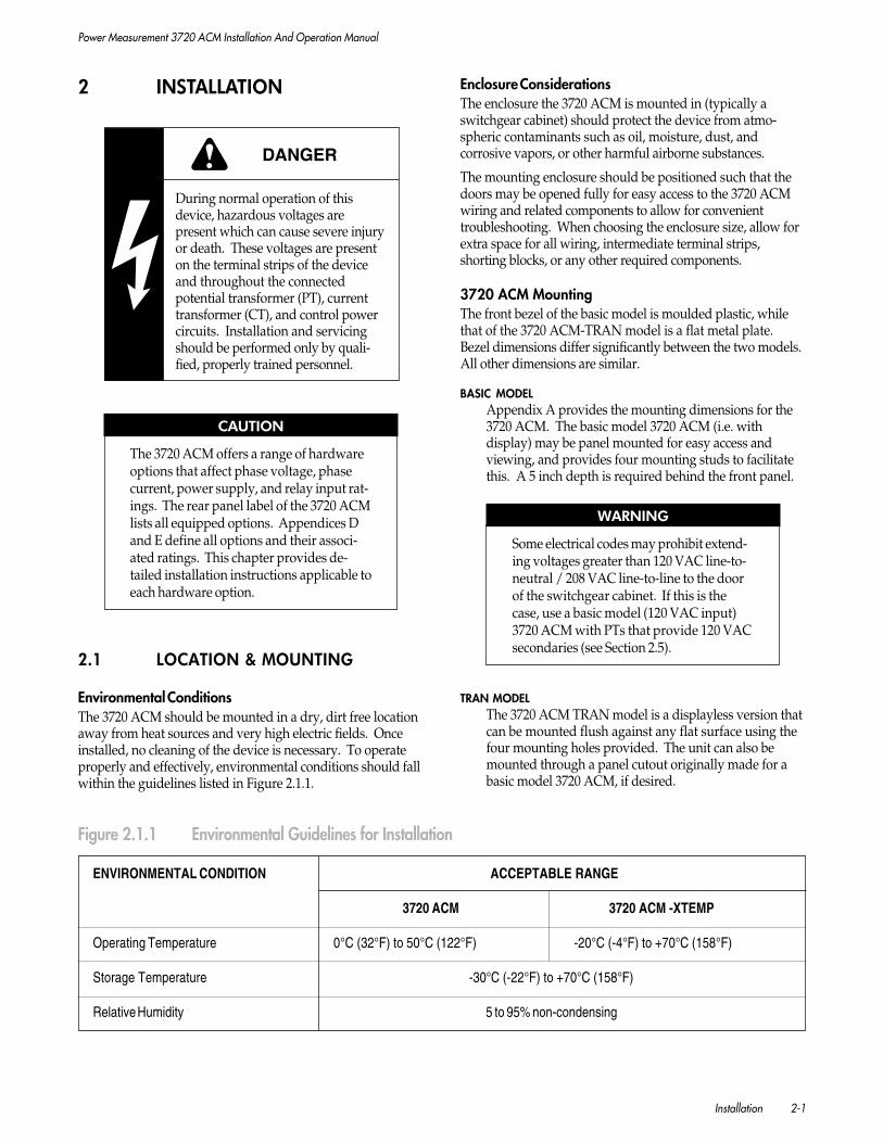
Enclosure ConsiderationsThe enclosure the 3720 ACM is mounted in (typically aswitchgear cabinet) should protect the device from atmo-spheric contaminants such as oil, moisture, dust, andcorrosive vapors, or other harmful airborne substances.
The mounting enclosure should be positioned such that thedoors may be opened fully for easy access to the 3720 ACMwiring and related components to allow for convenienttroubleshooting. When choosing the enclosure size, allow forextra space for all wiring, intermediate terminal strips,shorting blocks, or any other required components.
3720 ACM MountingThe front bezel of the basic model is moulded plastic, whilethat of the 3720 ACM-TRAN model is a flat metal plate.Bezel dimensions differ significantly between the two models.All other dimensions are similar.
BASIC MODELAppendix A provides the mounting dimensions for the3720 ACM. The basic model 3720 ACM (i.e. withdisplay) may be panel mounted for easy access andviewing, and provides four mounting studs to facilitatethis. A 5 inch depth is required behind the front panel.
WARNING
Some electrical codes may prohibit extend-ing voltages greater than 120 VAC line-to-neutral / 208 VAC line-to-line to the doorof the switchgear cabinet. If this is thecase, use a basic model (120 VAC input)3720 ACM with PTs that provide 120 VACsecondaries (see Section 2.5).
TRAN MODELThe 3720 ACM TRAN model is a displayless version thatcan be mounted flush against any flat surface using thefour mounting holes provided. The unit can also bemounted through a panel cutout originally made for abasic model 3720 ACM, if desired.
ENVIRONMENTAL CONDITION ACCEPTABLE RANGE
3720 ACM 3720 ACM -XTEMP
Operating Temperature 0°C (32°F) to 50°C (122°F) -20°C (-4°F) to +70°C (158°F)
Storage Temperature -30°C (-22°F) to +70°C (158°F)
Relative Humidity 5 to 95% non-condensing
Figure 2.1.1 Environmental Guidelines for Installation
2 INSTALLATION
DANGER
During normal operation of thisdevice, hazardous voltages arepresent which can cause severe injuryor death. These voltages are presenton the terminal strips of the deviceand throughout the connectedpotential transformer (PT), currenttransformer (CT), and control powercircuits. Installation and servicingshould be performed only by quali-fied, properly trained personnel.
CAUTION
The 3720 ACM offers a range of hardwareoptions that affect phase voltage, phasecurrent, power supply, and relay input rat-ings. The rear panel label of the 3720 ACMlists all equipped options. Appendices Dand E define all options and their associ-ated ratings. This chapter provides de-tailed installation instructions applicable toeach hardware option.
2.1 LOCATION & MOUNTING
Environmental ConditionsThe 3720 ACM should be mounted in a dry, dirt free locationaway from heat sources and very high electric fields. Onceinstalled, no cleaning of the device is necessary. To operateproperly and effectively, environmental conditions should fallwithin the guidelines listed in Figure 2.1.1.

Power Measurement 3720 ACM Installation And Operation Manual
2-2 Installation
CAUTION
A switch or circuit breaker should be in-cluded in the installation, in close proxim-ity to the unit and within easy reach to theoperator. This switch or circuit breakershould be marked as the disconnectingdevice for the unit.
2.2 GENERAL WIRING CONSIDERATIONS
Connections to the 3720 ACM are made to two terminal stripslocated on the rear of the unit. Appendix A provides 3720ACM terminal block dimensions. 12 to 14 gauge wire isrecommended for all connections. Ring or spade terminalsmay be used to simplify connection.
CAUTION
1. All wiring must conform to any appli-cable local electrical codes, and deviceterminals (once installed) should notbe user accessible.
2. In applications where the on-boardrelays are being used to perform criti-cal equipment control operations (e.g.breaker trip, etc.), special precautionsare required. See Section 2.7.
2.2.1 FIELD SERVICE
If the 3720 ACM requires servicing or field upgrading, youmay need to disconnect and remove the unit from its mount-ing. The initial installation should be done in a way thatmakes this as convenient as possible:
• All phase voltage sense leads should be protected bybreakers or fuses at their source such that the 3720ACM can be safely disconnected.
• A CT shorting block should be provided so that the3720 ACM current inputs can be safely disconnectedwithout open circuiting the CTs. The shorting blockshould be wired so that protective relaying is notaffected.
• All wiring should be routed to allow easy removal ofthe connections to the 3720 ACM terminal strips, the3720 ACM cover, and the 3720 ACM itself.
2.3 POWER SUPPLY CONNECTIONS
Power Supply Options
BASIC MODELThe basic model 3720 ACM can be powered by 100 to 240VAC (± 10%) or 110 to 300 VDC at 0.2 Amps. Powersupply options are also available. The label on the rearpanel indicates if the unit is equipped with one of theseoptions.
P24/48 OPTIONThis option can be powered by 20 to 60 VDC at 15 Watts.
Power Sources and ConnectionsThe basic model can be powered from a dedicated fused feed,or from the voltage source which it is monitoring, as long as itis within the supply range. The P24/48 option must bepowered from a dedicated fused feed. If an AC power supplyis being used, connect the line supply wire to the 3720 ACML/+ terminal and the neutral supply wire to the N/- terminal.If a DC power supply is being used, connect the positivesupply wire to the 3720 ACM L/+ terminal and the negative(ground) supply wire to the N/- terminal.
2.4 CHASSIS GROUND CONNECTION
The chassis of the 3720 ACM must be connected to earthground. A good, low impedance chassis ground connection isessential for the 3720 ACM surge and transient protectioncircuitry to function effectively. It should be made to theswitchgear earth ground using a dedicated 14 gauge (orlarger) wire to a point where there will be no voltage error dueto distribution voltage drops. Do not rely on metal doorhinges as a ground path.
Ground wire connection to the chassis is made using thesupplied ground lug. For the basic model, this is attached toone of the four mounting studs to form the protective groundterminal . For the TRAN model, the lug is attached to oneof four mounting bolts to form the protective ground terminal
.
NOTE
The VAUX input and IOUT output operatewith reference to chassis ground. Do notuse the protective ground terminal toconnect the VAUX or IOUT functionalground.
Ensure that the protective ground terminal screw istightened down securely onto the ground wire, and that thenut has been tightened down securely onto the lug.

Power Measurement 3720 ACM Installation And Operation Manual
Installation 2-3
CAUTION
The 3720 ACM chassis ground lug must beconnected to the switchgear earth groundusing a dedicated 14 gauge (or larger) wirefor the noise and surge protection circuitryto function correctly. Failure to do so willvoid the warranty.
2.5 PHASE VOLTAGE AND PHASECURRENT INPUT CONNECTIONS
2.5.1 PHASE VOLTAGE INPUTS
Maximum Terminal VoltagesThe maximum constant voltage levels the phase voltageinputs can withstand are as follows:
Voltage Option Maximum Terminal Voltage
120 150 VAC line-to-neutral, or260 VAC line-to-line
277 346 VAC line-to-neutral, or600 VAC line-to-line
347 434 VAC line-to-neutral, or750 VAC line-to-line
V1 Input ConnectionThe 3720 ACM uses the V1 input as the reference for main-taining phase relationships for all power and energy relatedmeasurements. For any system configuration, the V1 inputmust be connected to ensure accurate readings and the correctoperation of the 3720 ACM.
Direct ConnectionWhether or not potential transformers (PTs) are requireddepends on the nature of the system being monitored, thevoltage levels to be monitored, and the input option of the3720 ACM.
BASIC MODELThe basic model can be used for direct connection to Wyesystems up to 120 VAC line-to-neutral / 208 VAC line-to-line or Single Phase systems up to 120 VAC line-to-neutral / 240 VAC line-to-line.
277 OPTIONThis option provides 277 VAC full scale inputs that canbe used for direct connection to Wye systems up to 277VAC line-to-neutral / 480 VAC line-to-line or 277 VACline-to-neutral / 554 VAC line-to-line Single Phasesystems.
347 OPTIONModels supplied with the 347 option provide 347VAC full scale inputs that can be used for directconnection to 347 VAC line-to-neutral / 600 VACline-to-line Wye or Single Phase systems up to 347VAC line-to-neutral / 694 VAC line-to-line.
Using Potential TransformersIf Wye system voltages are over 347 VAC line-to-neutral /600 VAC line-to-line or Single Phase system voltages areover 347 VAC line-to-neutral / 694 VAC line-to-line,potential transformers (PTs) are required.
NOTE
PTs are always required for Deltasystems.
PTs are used to scale down the line-to-neutral voltage of aWye or Single Phase system, or the line-to-line voltage of aDelta system to the rated input scale of the 3720 ACM.The inputs of the basic model can be used with PTs thathave secondaries rated at 120 VAC or less. This caninclude 100/√3, 110/√3, 100, 110, or 120 VAC secondar-ies. Devices equipped with the 277 option can be usedwith PTs that have secondaries rated to 277 VAC, such as220 VAC.
For proper monitoring, correct selection of PTs is critical.For Wye systems, the PT primary rating should equal thesystem line-to-neutral voltage or nearest higher standardsize. For Delta systems, the PT primary rating shouldequal the system line-to-line voltage. For all systemconfigurations, the PT secondary rating must be withinthe rated full scale range of the 3720 ACM voltage inputs.
PT quality directly affects system accuracy. The PTs mustprovide good linearity and maintain the proper phaserelationship between voltage and current in order for thevoltage, kW, and power factor readings to be valid.Instrument Accuracy Class 1 or better is recommended.
2.5.2 PHASE CURRENT INPUTS
The 3720 ACM uses CTs to sense the current in eachphase of the power feed and (optionally) in the neutral orground conductor. The selection of the CTs is importantbecause it directly affects accuracy.
Current Input OptionsThe 3720 ACM offers various phase current input optionsto match the type of CTs being used and the desiredoverrange capability. The current input ratings of allthree phase inputs and the I4 input are equivalent.
The basic model 3720 ACM is compatible with CTs with 5Amp full scale secondaries.

Power Measurement 3720 ACM Installation And Operation Manual
2-4 Installation
The basic model 3720 ACM provides 125% overrange capabil-ity which allows current readings to be accurately displayed upto 125% of full scale. For example, if the AMPS SCALE hasbeen set at 2000 Amps full scale, the 3720 ACM allows forreadings up to 2500 Amps.
The 3720 ACM provides three additional current inputoverrange options which include 200%, 500%, and 1000%.Note that each overrange option also affects all current-related measurement accuracies (Amps, kW, etc.) Refer toAppendix D for detailed specifications on each current inputoption.
CAUTION
Refer to the rear panel label of the 3720ACM to determine the equipped currentinput option(s). Applying current levelsincompatible with the current input con-figuration will permanently damage thedevice.
CT RatingsThe CT secondary should have a burden capacity greater than3 VA.
The CT primary rating is normally selected to be equal to thecurrent rating of the power feed protection device. However,if the peak anticipated load is much less than the ratedsystem capacity, you can improve accuracy and resolution byselecting a lower rated CT. In this case the CT size should bethe maximum expected peak current +25%, rounded up to thenearest standard CT size.
Other factors may affect CT accuracy. The length of the CTcabling should be minimized because long cabling contributesto inaccuracy. Also, the CT burden rating must exceed thecombined burden of the 3720 ACM plus cabling plus anyother connected devices (burden is the amount of load beingfed by the CT, measured in Volt-Amps). The 3720 ACMburden rating is given in Appendix D.
Overall accuracy is dependent on the combined accuracies ofthe 3720 ACM, the CTs, and the PTs (if used). Instrumentaccuracy Class 1 or better is recommended.
2.5.3 PT & CT CONNECTION
Figures 2.5.7a to 2.5.9 illustrate all required phase voltage andphase current connections for various circuit configurations toensure correct installation. Phasing and polarity of the ACcurrent and voltage inputs and their relationship is critical tothe correct operation of the unit.
All phase voltage sense leads should be protected by breakersor fuses at their source. In cases where PTs are required, if thepower rating of the PTs is over 25 Watts the secondariesshould be fused.
CTs should be connected to the device via a shorting block ortest block to facilitate the safe connection and disconnectionof the CTs.
DANGER
PT secondary circuits are capable ofgenerating lethal voltages and currentswith their primary circuit energized.Standard safety precautions should befollowed while performing anyinstallation or service on the device(e.g. removing PT fuses, etc.)
DANGER
CT secondary circuits are capable ofgenerating lethal voltages andcurrents when open circuited withtheir primary circuit energized.Standard safety precautions shouldbe followed while performing anyinstallation or service on the device(e.g. shorting CT secondaries, etc.)
Refer all questions regarding proper working procedures toqualified personnel.
2.5.4 VOLTAGE REFERENCE CONNECTION
The voltage reference terminal, VREF, of the 3720 ACM servesas the zero voltage reference for voltage readings. A good,low impedance VREF connection is essential for accuratemeasurement. It should be made using a dedicated 14 gaugewire to a point where there will be no voltage error due todistribution voltage drops.
The connection point for VREF is dependent on the systemconfiguration. Each of the following configurations isillustrated in Figures 2.5.7a to 2.5.9:
• If the system being monitored is 4-wire Wye or SinglePhase, VREF must be connected to the neutral conduc-tor.
• If the system is 3-wire grounded (Delta), VREF must beconnected to the line transformer neutral.
• For 3-wire ungrounded (Open Delta) systems, and forsystems where PTs are being used, VREF must beconnected to the PT common leads.
Power Measurement 3720 ACM Installation And Operation Manual
Installation 2-5
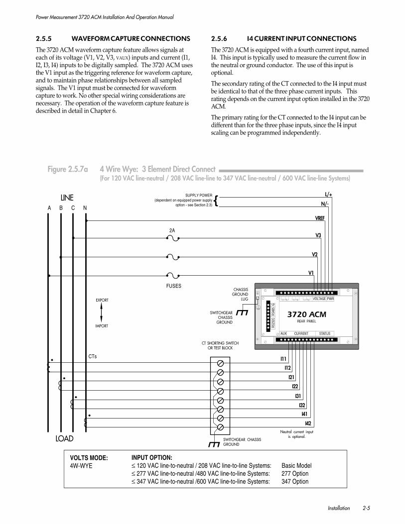
2.5.5 WAVEFORM CAPTURE CONNECTIONS
The 3720 ACM waveform capture feature allows signals ateach of its voltage (V1, V2, V3, VAUX) inputs and current (I1,I2, I3, I4) inputs to be digitally sampled. The 3720 ACM usesthe V1 input as the triggering reference for waveform capture,and to maintain phase relationships between all sampledsignals. The V1 input must be connected for waveformcapture to work. No other special wiring considerations arenecessary. The operation of the waveform capture feature isdescribed in detail in Chapter 6.
2.5.6 I4 CURRENT INPUT CONNECTIONS
The 3720 ACM is equipped with a fourth current input, namedI4. This input is typically used to measure the current flow inthe neutral or ground conductor. The use of this input isoptional.
The secondary rating of the CT connected to the I4 input mustbe identical to that of the three phase current inputs. Thisrating depends on the current input option installed in the 3720ACM.
The primary rating for the CT connected to the I4 input can bedifferent than for the three phase inputs, since the I4 inputscaling can be programmed independently.
VOLTS MODE:4W-WYE
INPUT OPTION:≤ 120 VAC line-to-neutral / 208 VAC line-to-line Systems: Basic Model≤ 277 VAC line-to-neutral /480 VAC line-to-line Systems: 277 Option≤ 347 VAC line-to-neutral /600 VAC line-to-line Systems: 347 Option
FUSES
LOAD
CHASSISGROUND
LUG
Neutral current inputis optional.
SWITCHGEARCHASSIS
GROUND
N/-
L/+
VREF
V3
V2
V1
CTs
2A
IMPORT
EXPORT
A B C N
LINE
SWITCHGEAR CHASSISGROUND
CT SHORTING SWITCHOR TEST BLOCK
{SUPPLY POWER
(dependent on equipped power supplyoption - see Section 2.3)
I42
I41
I12
I11
I21
I22
I31
I32
Figure 2.5.7a 4 Wire Wye: 3 Element Direct Connect (For 120 VAC line-neutral / 208 VAC line-line to 347 VAC line-neutral / 600 VAC line-line Systems)
Power Measurement 3720 ACM Installation And Operation Manual
2-6 Installation
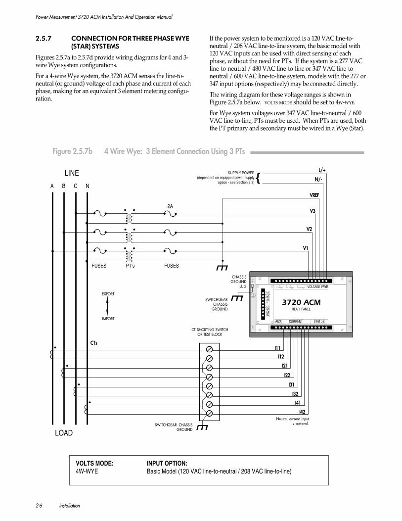
2.5.7 CONNECTION FOR THREE PHASE WYE(STAR) SYSTEMS
Figures 2.5.7a to 2.5.7d provide wiring diagrams for 4 and 3-wire Wye system configurations.
For a 4-wire Wye system, the 3720 ACM senses the line-to-neutral (or ground) voltage of each phase and current of eachphase, making for an equivalent 3 element metering configu-ration.
If the power system to be monitored is a 120 VAC line-to-neutral / 208 VAC line-to-line system, the basic model with120 VAC inputs can be used with direct sensing of eachphase, without the need for PTs. If the system is a 277 VACline-to-neutral / 480 VAC line-to-line or 347 VAC line-to-neutral / 600 VAC line-to-line system, models with the 277 or347 input options (respectively) may be connected directly.
The wiring diagram for these voltage ranges is shown inFigure 2.5.7a below. VOLTS MODE should be set to 4W-WYE.
For Wye system voltages over 347 VAC line-to-neutral / 600VAC line-to-line, PTs must be used. When PTs are used, boththe PT primary and secondary must be wired in a Wye (Star).
INPUT OPTION:Basic Model (120 VAC line-to-neutral / 208 VAC line-to-line)
VOLTS MODE:4W-WYE
FUSES PT's FUSES
LOAD
SWITCHGEARCHASSIS
GROUND
SWITCHGEAR CHASSISGROUND
I42
I41
I31
I32
I22
I21
I12
I11
Neutral current inputis optional.
VREF
V2
V1
CTs
CHASSISGROUND
LUG
2AV3
A B C N
LINE
IMPORT
EXPORT
CT SHORTING SWITCHOR TEST BLOCK
N/-
L/+
{SUPPLY POWER
(dependent on equipped power supplyoption - see Section 2.3)
Figure 2.5.7b 4 Wire Wye: 3 Element Connection Using 3 PTs

Power Measurement 3720 ACM Installation And Operation Manual
Installation 2-7
Voltage sense leads should be protected by breakers or fuses attheir source. Wiring must be exactly as shown for correctoperation.
This configuration is shown in Figure 2.5.7b. VOLTS MODE
should be set to 4W-WYE.
The 3720 ACM also supports a 2½-element connectionscheme which requires only two PTs. In this mode, the phaseB voltage displayed on the front panel is derived from theavailable voltages.
This configuration is shown in Figure 2.5.7c. VOLTS MODE
should be set to 3W-WYE.
WARNING
VOLTS MODE = 3W-WYE only provides accuratepower measurement if the voltages are bal-anced. If the phase B voltage is not equal tothe phase A and C voltages, the powerreadings may not meet the 3720 ACM accu-racy specifications.
VOLTS MODE:3W-WYE
INPUT OPTION:Basic Model (120 VAC line-to-neutral / 208 VAC line-to-line)
SWITCHGEAR CHASSISGROUND
LOAD
CHASSISGROUND
LUG
SWITCHGEARCHASSISGROUND
CTs
SWITCHGEARCHASSIS GROUND
VREF
LINE V2
V3
V1
FUSES PT's FUSES
IMPORT
EXPORT
A B C N/G2A
CT SHORTING SWITCHOR TEST BLOCK
I42
I41
I31
I32
I22
I21
I12
I11
Neutral current inputis optional.
{SUPPLY POWER
(dependent on equipped power supplyoption - see Section 2.3)
N/-
L/+
Figure 2.5.7c 4 Wire Wye: 2½ Element Connection Using 2 PTs
Power Measurement 3720 ACM Installation And Operation Manual
2-8 Installation
N
A B C
FUSES
LINE
CTs
LOAD
CHASSISGROUND
LUG
SWITCHGEARCHASSISGROUND
VREF
V2V3
V12A
IMPORT
EXPORT
SWITCHGEAR CHASSISGROUND
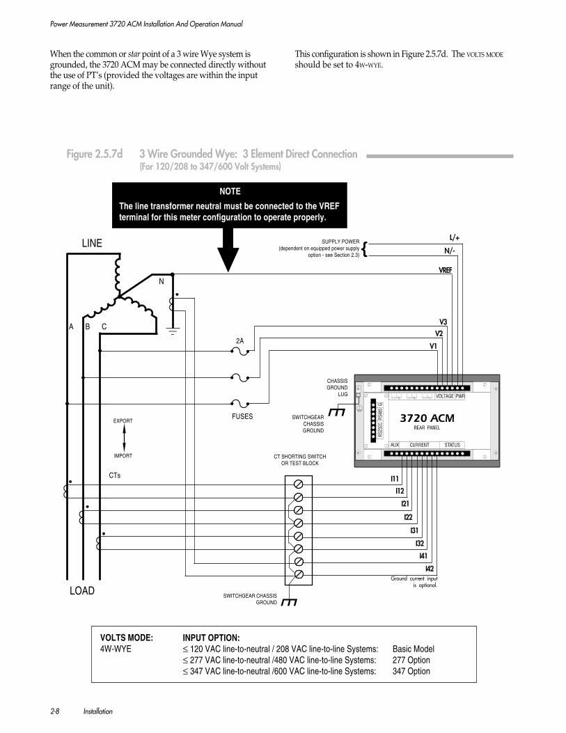
NOTE
The line transformer neutral must be connected to the VREFterminal for this meter configuration to operate properly.
I42
I41
I31
I32
I22
I21
I12
I11
CT SHORTING SWITCHOR TEST BLOCK
{SUPPLY POWER
(dependent on equipped power supplyoption - see Section 2.3)
N/-
L/+
When the common or star point of a 3 wire Wye system isgrounded, the 3720 ACM may be connected directly withoutthe use of PT’s (provided the voltages are within the inputrange of the unit).
This configuration is shown in Figure 2.5.7d. The VOLTS MODE
should be set to 4W-WYE.
Figure 2.5.7d 3 Wire Grounded Wye: 3 Element Direct Connection(For 120/208 to 347/600 Volt Systems)
VOLTS MODE:4W-WYE
INPUT OPTION:≤ 120 VAC line-to-neutral / 208 VAC line-to-line Systems: Basic Model≤ 277 VAC line-to-neutral /480 VAC line-to-line Systems: 277 Option≤ 347 VAC line-to-neutral /600 VAC line-to-line Systems: 347 Option
Ground current inputis optional.
Power Measurement 3720 ACM Installation And Operation Manual
Installation 2-9
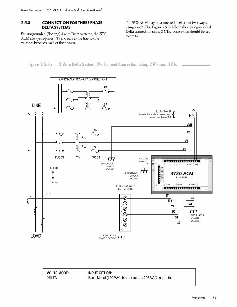
2.5.8 CONNECTION FOR THREE PHASEDELTA SYSTEMS
For ungrounded (floating) 3 wire Delta systems, the 3720ACM always requires PTs and senses the line-to-linevoltages between each of the phases.
VCB
V AB
A B C
FUSES PT's FUSES
LINE
CTs
LOAD
CHASSISGROUND
LUG
SWITCHGEARCHASSISGROUND
SWITCHGEARCHASSIS GROUND
SWITCHGEARCHASSISGROUND
SWITCHGEARCHASSISGROUND
VREF
V3
V2
V1
2A
IMPORT
EXPORT
2A
2A
2A
OPTIONAL PT POLARITY CONNECTION
I31
I32
I22
I21
I12
I11
I41
I42
CT SHORTING SWITCHOR TEST BLOCK
N/-
L/+
{SUPPLY POWER
(dependent on equipped power supplyoption - see Section 2.3)
The 3720 ACM may be connected in either of two ways:using 2 or 3 CTs. Figure 2.5.8a below shows ungroundedDelta connection using 3 CTs. VOLTS MODE should be setto DELTA.
Figure 2.5.8a 3 Wire Delta System: 2½ Element Connection Using 2 PTs and 3 CTs
INPUT OPTION:Basic Model (120 VAC line-to-neutral / 208 VAC line-to-line)
VOLTS MODE:DELTA

Power Measurement 3720 ACM Installation And Operation Manual
2-10 Installation
Figure 2.5.8b below shows ungrounded Delta connectionusing 2 CT’s. VOLTS MODE should be set to DELTA.
2A
OPTIONAL PT POLARITY CONNECTION
VCB
VAB
A B C
FUSES PT's FUSES
LINE
SWITCHGEAR CHASSISGROUND
CHASSISGROUND
LUG
SWITCHGEARCHASSISGROUND
SWITCHGEARCHASSISGROUND
SWITCHGEARCHASSISGROUND
LOAD
CT's
2A
IMPORT
EXPORT
2A
2A
I31
I32
I22
I21
I12
I11 I42
I41
VREF
V3
V2
V1
CT SHORTING SWITCHOR TEST BLOCK
{SUPPLY POWER
(dependent on equipped power supplyoption - see Section 2.3)
N/-
L/+
VOLTS MODE:DELTA
INPUT OPTION:Basic Model (120 VAC line-to-neutral / 208 VAC line-to-line)
Figure 2.5.8b 3 Wire Delta: 2 Element Connection Using 2 PTs and 2 CTs

Power Measurement 3720 ACM Installation And Operation Manual
Installation 2-11
2.5.9 CONNECTION FOR SINGLE PHASESYSTEMS
Wiring for Single Phase systems is performed by connectingthe two voltage phases (each 180 degrees with respect to eachother) to the V1 and V2 inputs of the 3720 ACM, and theoutputs of the two corresponding current transformers to theI1 input pair and I2 input pair.
This is illustrated in Figure 2.5.9 below. Note that the V3 inputand I3 input pair are unused and should all be grounded. ForSingle Phase systems, the VOLTS MODE of the 3720 ACM shouldbe set to SINGLE.
VOLTS MODE:SINGLE
INPUT OPTION:≤ 120 VAC line-to-neutral / 240 VAC line-to-line Systems: Basic Model≤ 277 VAC line-to-neutral / 554 VAC line-to-line Systems: 277 Option≤ 347 VAC line-to-neutral / 694 VAC line-to-line Systems: 347 Option
FUSES
A B N
LINE
CT's
LOAD SWITCHGEAR CHASSISGROUND
SWITCHGEARCHASSISGROUND
SWITCHGEARCHASSISGROUND
CHASSISGROUND
LUG
2A
IMPORT
EXPORT
VREF
V3
V2
V1
I32
I31
I22
I21
I12
I11
Neutral current inputis optional.
I42
I41
CT SHORTING SWITCHOR TEST BLOCK
{SUPPLY POWER
(dependent on equipped power supplyoption - see Section 2.3)
N/-
L/+
Figure 2.5.9 3 Wire Single Phase: 2 Element Direct Connection
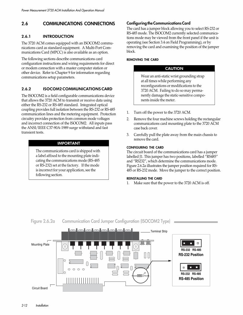
Power Measurement 3720 ACM Installation And Operation Manual
2-12 Installation
2.6 COMMUNICATIONS CONNECTIONS
2.6.1 INTRODUCTION
The 3720 ACM comes equipped with an ISOCOM2 commu-nications card as standard equipment. A Multi-Port Com-munications Card (MPCC) is also available as an option.
The following sections describe communications cardconfiguration instructions and wiring requirements for director modem connection with a master computer station orother device. Refer to Chapter 9 for information regardingcommunications setup parameters.
2.6.2 ISOCOM2 COMMUNICATIONS CARD
The ISOCOM2 is a field configurable communications devicethat allows the 3720 ACM to transmit or receive data usingeither the RS-232 or RS-485 standard. Integrated opticalcoupling provides full isolation between the RS-232 or RS-485communication lines and the metering equipment. Protectioncircuitry provides protection from common mode voltagesand incorrect connection of the ISOCOM2. All inputs passthe ANSI/IEEE C37-90A-1989 surge withstand and fasttransient tests.
IMPORTANT
The communications card is shipped witha label affixed to the mounting plate indi-cating the communications mode (RS-485or RS-232) set at the factory. If the modeis incorrect for your application, see thefollowing section.
Configuring the Communications CardThe card has a jumper block allowing you to select RS-232 orRS-485 mode. The ISOCOM2 currently selected communica-tions mode may be viewed from the front panel if the unit isoperating (see Section 3.4 on Field Programming), or byremoving the card and examining the position of the jumperblock.
REMOVING THE CARD
CAUTION
Wear an anti-static wrist grounding strapat all times while performing anyreconfigurations or modifications to the3720 ACM. Failing to do so may perma-nently damage the static-sensitive compo-nents inside the meter.
1. Turn off the power to the 3720 ACM.
2. Remove the four machine screws holding the rectangularcommunications card mounting plate to the 3720 ACMcase back cover.
3. Carefully pull the plate away from the main chassis toremove the card.
CONFIGURING THE CARDThe circuit board of the communications card has a jumperlabelled J1. This jumper has two positions, labelled “RS485”and “RS232”, which determine the communications mode.Figure 2.6.2a illustrates the jumper position required for RS-485 or RS-232 mode. Move the jumper to the correct position.
REINSTALLING THE CARD1. Make sure that the power to the 3720 ACM is off.
Mounting Plate
Terminal Strip
Circuit Board
Figure 2.6.2a Communication Card Jumper Configuration (ISOCOM2 Type)
RS-232 PositionRS-232 RS-485
RS-232 RS-485
RS-485 Position
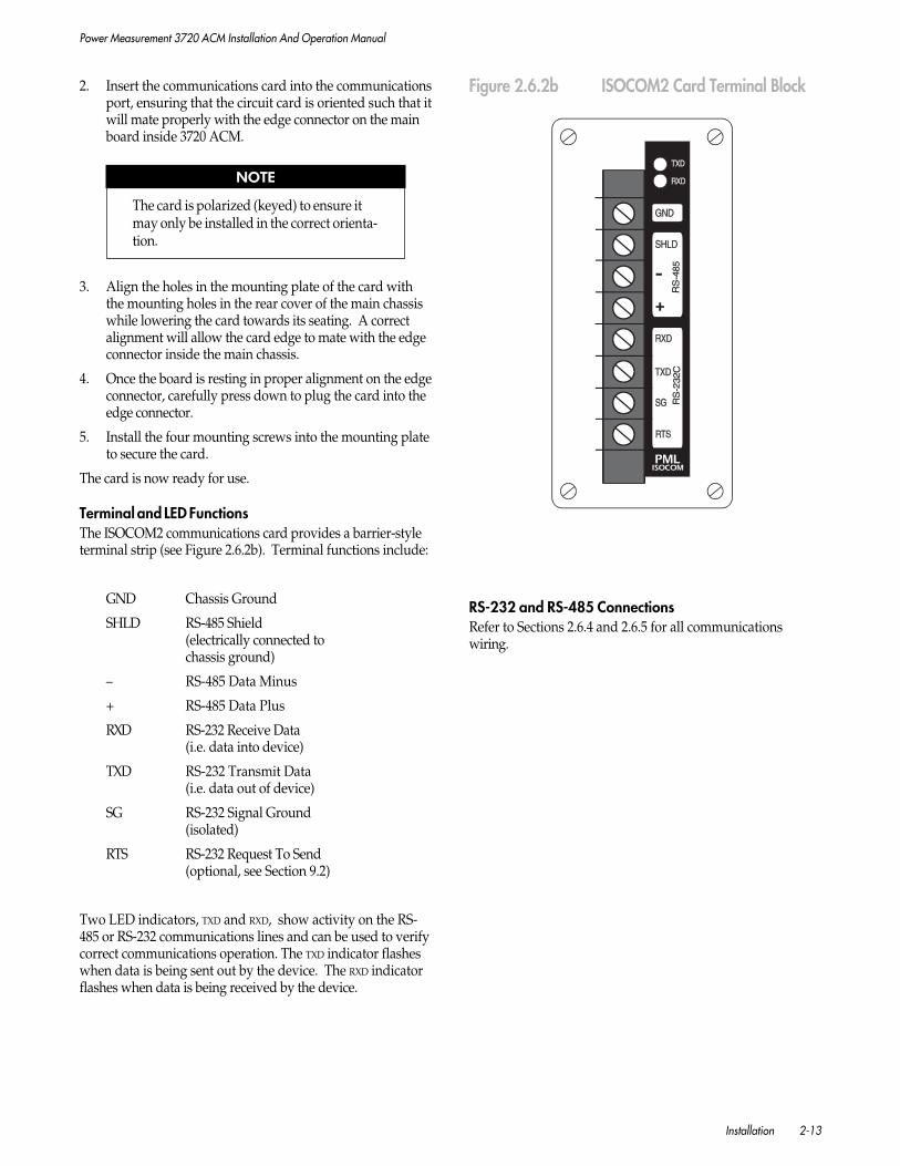
Power Measurement 3720 ACM Installation And Operation Manual
Installation 2-13
2. Insert the communications card into the communicationsport, ensuring that the circuit card is oriented such that itwill mate properly with the edge connector on the mainboard inside 3720 ACM.
NOTE
The card is polarized (keyed) to ensure itmay only be installed in the correct orienta-tion.
3. Align the holes in the mounting plate of the card withthe mounting holes in the rear cover of the main chassiswhile lowering the card towards its seating. A correctalignment will allow the card edge to mate with the edgeconnector inside the main chassis.
4. Once the board is resting in proper alignment on the edgeconnector, carefully press down to plug the card into theedge connector.
5. Install the four mounting screws into the mounting plateto secure the card.
The card is now ready for use.
Terminal and LED FunctionsThe ISOCOM2 communications card provides a barrier-styleterminal strip (see Figure 2.6.2b). Terminal functions include:
GND Chassis Ground
SHLD RS-485 Shield(electrically connected tochassis ground)
– RS-485 Data Minus
+ RS-485 Data Plus
RXD RS-232 Receive Data(i.e. data into device)
TXD RS-232 Transmit Data(i.e. data out of device)
SG RS-232 Signal Ground(isolated)
RTS RS-232 Request To Send(optional, see Section 9.2)
Two LED indicators, TXD and RXD, show activity on the RS-485 or RS-232 communications lines and can be used to verifycorrect communications operation. The TXD indicator flasheswhen data is being sent out by the device. The RXD indicatorflashes when data is being received by the device.
Figure 2.6.2b ISOCOM2 Card Terminal Block
RS-232 and RS-485 ConnectionsRefer to Sections 2.6.4 and 2.6.5 for all communicationswiring.

Power Measurement 3720 ACM Installation And Operation Manual
2-14 Installation
2.6.3.a MULTIPORT COMMUNICATIONS CARD(MPCC)
The optional Multi-Port Communications Card allows the3720 ACM to communicate via three distinct ports (one RS-232 and two RS-485) within a multi-protocol environment.
NOTE
Only one RS-485 port (Port C) remainsfunctional if the Carrier Detect (CD) optionis enabled. This is described below.
Each port can be configured to operate with any of thesupported protocols (PML, Modbus, AB DF-1, Alarm Dialer).All ports can communicate simultaneously. Optical couplingprovides full isolation both between the RS-232 and RS-485communication ports, the two RS-485 ports, and the meteringequipment. In addition, protection circuitry provides asafeguard from common mode voltages that may be appliedto the card due to incorrect connection of the MPCC.
Connections to the card are made by way of the eleven pin“captured wire” connector located on top of the card (seeFigure 2.6.3.a).
Communications Ports
PORT AStandard: RS-232, half duplex
Baud Rates: 300, 1200, 2400, 4800, 9600, 19200, 38400,57600, 115200 bps.
Signaling: Supports RTS (Request To Send) and CTS(Clear To Send) handshaking.
Protection: Withstand ANSI C37.90 fast transient.
Fully isolated from Port C.
PORT BStandard: RS-485, half duplex
Baud Rates: 300, 1200, 2400, 4800, 9600, 19200, 38400,57600, 115200 bps.
Protection: Withstand ANSI C37.90 fast transient,withstand 120V AC/DC applied to Data- and/orData+.
Fully isolated from Port C.
PORT CStandard: RS-485, half duplex
Baud Rates: 300, 1200, 2400, 4800, 9600, 19200, 38400,57600, 115200 bps.
Protection: Withstand ANSI C37.90 fast transient,withstand 120V AC/DC applied to Data- and/orData+.
Fully isolated from Port A and Port B.
Figure 2.6.3.a 3720 MPCC Connector Configuration
Terminal Block and LEDsThe Multi-Port Communications Card (MPCC) provides aphoenix-style connector strip (see Figure 2.6.3). Terminalfunctions include:
SHLD RS-485 shield for Port C (electricallyconnected to chassis ground)
- RS-485 Data Minus for Port C
+ RS-485 Data Plus for Port C
SHLD Port B (chassis ground)
CD / - Carrier Detect or RS-485 Data Minus forPort B (see next section)
SG / + Signal Ground for CD or RS-485 DataMinus for Port B (see next section)
SG Standard RS-232 Signal Ground
TXD RS-232 Transmit Data (data out)
RXD RS-232 Receive Data (data in)
CTS RS-232 Clear To Send (optional, see nextsection)
RTS RS-232 Request To Send (optional, seenext section)
Two LED indicators per port, TXD and RXD, show activity onthe RS-485 or RS-232 communications lines and can be usedto verify correct communications operation. The TXD indicatorflashes when data is being sent out by the device. The RXD
indicator flashes when data is being received by the device.

Power Measurement 3720 ACM Installation And Operation Manual
Installation 2-15
2.6.3.b MULTIPORT COMMUNICATIONS CARDWITH ETHERNET (MPE)
The optional MPE (Multiport Communications Card w/Ethernet) allows the 3720 ACM to communicate via threedistinct ports (one RS-232, one RS-485 and one Ethernet)within a multi-protocol environment. Each serial RS-232 orRS-485 port can be configured to operate with any of thesupported protocols (PML, Modbus, AB DF-1, Alarm Dialer).All ports can communicate simultaneously. Optical couplingprovides full isolation between the RS-232 / RS-485 ports, andthe Ethernet port / metering equipment. In addition,protection circuitry on the RS-485 port provides a safeguardfrom common mode voltages that may be applied to the RS-485 port due to incorrect connection of the MPE.
Connections to the card are made by way of the eight pin“captured wire” connector and a standard RJ-45 UTP(unshielded twisted pair) jack, located on top of the card (seeFigure 2.6.3.b).
Communications Ports
PORT AStandard: RS-232, half duplex
Baud Rates: 300, 1200, 2400, 4800, 9600, 19200, 38400,57600, 115200 bps.
Signaling: Supports RTS (Request To Send) and CTS(Clear To Send) handshaking.
Protection: Withstand ANSI C37.90.1 fast transient.
Fully isolated from Port C.
PORT BStandard: RS-485, half duplex
Baud Rates: 300, 1200, 2400, 4800, 9600, 19200, 38400,57600, 115200 bps.
Protection: Withstand ANSI C37.90.1 fast transient,withstand 120V AC/DC applied to Data- and/orData+.
Fully isolated from Port C.
PORT CStandard: Ethernet, IEEE 802.3 (10Base-T)
Baud Rate: 10 Megabits per second.
Fully isolated from Port A and Port B.
NOTE
Certain timing considerations apply whenusing Power Measurement COM32 andCOM128 RS232/RS485 converters withAllen Bradley DF-1 and Modicon Modbusprotocols. Contact Customer Service formore information.
Figure 2.6.3.b 3720 MPE Connector Configuration
3720 MPCC
TXD
ETHERNET
RXD
RXD
RXD
PO
RT
CP
OR
TB
TXD
TXD PO
RT
A
+
-
SHLD RS
-48
5
ET
HE
RN
ET
10
BA
SE
-T
SG
SG
TXD
RXD
RTS
CTS
CD
RS
-23
2
Terminal block and ledsThe MPCC-Ethernet (MPE) provides a standard RJ-45 UTPjack and a phoenix style connector strip (see Figure 2.6.3.b).Terminal functions include:
ETHERNET Ethernet jack for Port C
SHLD RS-485 shield for Port B (electrically connectedto chassis ground)
CD/- Carrier Detect or RS-485 Data Minus for Port B(see next section)
SG/+ Signal Ground or RS-485 Data Plus for Port B(see next section)
SG Standard RS-232 Signal Ground
TXD RS-232 Transmit Data (data out)
RXD RS-232 Receive Data (data in)
CTS RS-232 Clear To Send (optional; see nextsection)
RTS RS-232 Request To Send (optional; see nextsection)
Two LED indicators per port, TXD and RXD, show activity onthe Ethernet, RS-485 or RS-232 communications lines and canbe used to verify correct communications operation. The TXDindicator flashes when data is being sent out by the device.The RXD indicator flashes when data is being received by thedevice.

Power Measurement 3720 ACM Installation And Operation Manual
2-16 Installation
RS-232 Connections
TXD, RXD AND SGThese connections are identical to those used for theISOCOM2 RS-232 port. Refer to Section 2.6.4.
RTS AND CTSThe RTS line functions in an identical manner for the MPCCand MPE as for the ISOCOM2. Refer to Section 9.2.
NOTE
If CTS is not required, short the RTS andCTS lines together with a jumper wire be-tween the two connectors.
CARRIER DETECTCarrier Detect is designed for applications where a modem isin use. To use Carrier Detect, a jumper wire must be con-nected between the Carrier Detect Signal Ground (SG) and theadjacent PORT A RS-232 standard Signal Ground (SG). Seesection 9.2 for more information.
NOTE
The use of the CD option will disable PortB for use as an RS-485 port.
RS-485 ConnectionsConnections for each RS-485 port of the MPCC/MPE areidentical to those used on the ISOCOM2. Refer to Section2.6.5.
Ethernet connectionThe MPE connector consists of an RJ-45 jack. A UTP(unshielded twisted pair) 10Base-T cable connects the MPE toyour local area network (LAN).
COMMUNICATIONS PROTOCOLThe MPE communicates on an Ethernet network throughTCP/IP. This protocol suite is an open standard and is usedby the Internet.
NETWORK PARAMETERSRequired network parameter for proper operation is a uniqueIP address for the device (3720 ACM). This IP address istypically assigned by a Network Administrator. Optionalparameters include:
Network subnet mask (required if subnetting isapplicable)
Default gateway address (required if cross-communica-tion between networks is applicable)
BASIC CONFIGURATION
CAUTION !
To ensure proper integration with your ex-isting LAN/WAN, it is highly recom-mended that your Network Administratoractively participates in configuring yourMPE.
The IP address for the 3720 ACM must beset correctly before connecting the meter tothe network. Failure to do so may result innetwork problems
Using the front panel switches of the 3720 ACM, scroll andselect the following:
“Communications” menu
“Port C”
“Ethernet” protocol
Program the MPE’s unique IP address (assigned by yourNetwork Administrator) into the meter. The IP addressconsists of four blocks of numbers separated by periods.Enter each block of numbers in sequence.
For example, if the address is “192.168.2.150” (address shownhere is for illustration purposes only; this address will notwork on your network), you would enter this information asfollows:
• IPaddr1 = 192
• IPaddr2 = 168
• IPaddr3 = 2
• IPaddr4 = 150.
The remaining configuration steps can be performed viaTelnet, as described in the following section.
TELNET CONFIGURATIONUsing Telnet, connect to the IP address associated with the3720 ACM. Log into the MPE as follows:
1. At the user name prompt, enter “pml”.
2. At the password prompt, enter your 3720 ACM meterpassword.
A menu containing available options can be displayed bytyping “?”. To change the IP address, subnet mask orgateway address, type in the appropriate menu number andenter the information at the prompts.
Other configurable parameters are listed below (note thatthese only affect protocols being used on the Ethernet port):

Power Measurement 3720 ACM Installation And Operation Manual
Installation 2-17
SUPPORTED PROTOCOLS OVER TCP/IPCurrently, the MPE supports the PML and Modbus protocols.
FUTURE FIRMWARE UPGRADESFor ease of upgrading firmware, PML recommends thatunused RS-232 or RS-485 ports be pre-wired, the reason beingthat upgrades are downloaded through the serial ports.Upgrading through the Ethernet port is not supported.
2.6.4 RS-232 CONNECTIONS
Figure 2.6.4a illustrates the wiring requirements for connec-tion of the 3720 ACM using RS-232 communications. Thiscan include a local direct connection to a computer or otherdevice, or a remote connection via modem.
NOTE
For information on remote connections viamodem (telephone, fibre optic, radio etc.)contact POWER MEASUREMENT CustomerService.
The RS-232 standard allows only a single point-to-pointcommunications connection. Using this method, only oneRS-232 equipped device may be connected to the serial port ofthe computer, modem, or other device.
1. See Figure 2.6.4b for RS-232 cable connections.
2. RTS, CTS, and CD connections are optional. See Section 2.6.3.
NOTE
IBM PC (DTE)
IBM PC (DTE)
RS-232Port
Telephone, Radio,or Fibre Optic
Modem
Telephone, Radio,or Fibre Optic
ModemTelephoneNetwork
RS-232Cable
RS-232Cable
3720 ACM
RS-232 PORT
TXD RXD SGRS-232 Cable
50 ft. maximum
Figure 2.6.4a RS-232 Communications Connections
TXD
3720 ACM
RS-232 PORT
TXD RXD SG
• PML protocol password protect: Entering a value herespecifies whether or not a password will be required toprogram the 3720 ACM, when it uses PML 3720protocol over TCP/IP. This parameter can also beconfigured using the front panel buttons of the 3720ACM.
• Modbus protocol password protect: Same as above,except for when it uses Modbus protocol over TCP/IP.
• Modbus register size: Select either 16 or 32 bit regis-ters.
• Enabling or disabling possible additional Ethernetconnections to the MPE: If either or both serialconnections are set to “None”, additional Ethernetconnections can be made (a total of three connectionscan be made through the 10BaseT port). If required,these additional Ethernet connections may be explic-itly disabled as well (disabling the additional Ethernetconnections does not affect the use of the serial ports).Note that a Telnet connection cannot be locked out; ifall three Ethernet connections are in use, one will bedisrupted when a Telnet connection is initiated.
The MPE can also be completely configured via serial ports Aor B. Contact Power Measurement for details.

Power Measurement 3720 ACM Installation And Operation Manual
2-18 Installation
Figure 2.6.4b RS-232 Communication Cable Wiring
DB9 (9 pins) MALE
DB9 (9 pins) FEMALE
DB25 (25 pins) MALE
DB25 (25 pins) FEMALE
1 13
13 1
6 9
9 625 14
1 4 25
5 1
1 5
RS-232 CONNECTOR PINOUTS
2 3 Transmit (TX)3 2 Receive (RX)5 7 Signal Gnd (SG)7 4 Request To Send (RTS)8 5 Clear To Send (CTS)6 6 Data Set Ready (DSR)4 20 Data Terminal Ready (DTR)
3720 ACM RS-232 Port
FUNCTIONDB9 DB25 FUNCTION
DCE
Receive (RXD)Transmit (TXD)Signal Gnd (SG)Request To Send (RTS)Clear To Send (CTS)
Always jumper DSRto DTR at DCE end.
Jumper RTS to CTS atDCE end if not used.
3 2 Transmit (TX)2 3 Receive (RX)5 7 Signal Gnd (SG)7 4 Request To Send (RTS)8 5 Clear To Send (CTS)6 6 Data Set Ready (DSR)4 20 Data Terminal Ready (DTR)
3720 ACM RS-232 Port
FUNCTIONDB9 DB25 FUNCTION
DTE
Receive (RXD)Transmit (TXD)Signal Gnd (SG)Request To Send (RTS)Clear To Send (CTS)
Always jumper RTSto CTS at DTE end.
Always jumper DSRto DTR at DTE end.
Note: When using a MPCC, RTSand CTS lines must be jumpered.
RS-232 SERIAL CABLE WIRING CONNECTIONS
Note: Clear To Send (CTS) is onlyused with a MPCC.
Note: All references to MPCC apply to MPE as well

Power Measurement 3720 ACM Installation And Operation Manual
Installation 2-19
Figure 2.6.4b illustrates all RS-232 cable configurations andwiring connections.
The cable used between a computer and modem (if used) is astandard straight-through RS-232 communications cable witha maximum length of 50 feet (15.2m). Refer to the installationmanuals for both the computer and modem for cable require-ments.
Typically, a computer is configured as a DTE device, whereasa modem is configured as a DCE device. Note that this is notalways the case; refer to the computer and/or modem usersmanual for correct configuration.
The cables used between a DTE device and the 3720 ACM, ora DCE device and the 3720 ACM are each custom RS-232cables. In each case, one end is equipped with a DB25 orDB9, male or female connector. The connector requireddepends on the mating connector of the computer or modemserial port. The other end of the cable consists of discretewires which connect to the RS-232 terminals of the 3720ACM. Cable length is 50 feet (15.2 m) maximum.
Refer to Chapter 9 for information regarding the use of theRTS line of the 3720 ACM.
2.6.5 RS-485 CONNECTIONS
RS-485 communications allows multiple devices to be con-nected on the same bus. Up to 32 devices can be connectedon a single RS-485 bus, which consists of a shielded twistedpair cable. The overall length of the RS-485 cable connectingall devices cannot exceed 4000 ft. (1219 m).
To connect an RS-485 communications bus to a computer orother RS-232 equipped device, an RS-232 to RS-485 converteris required, such as POWER MEASUREMENT’s COM32 orCOM128. The COM32 offers a single RS-485 port, while the
COM128 offers a total of four RS-485 ports that can eachsupport up to 32 devices.
General Bus Wiring ConsiderationsDevices connected on the bus, including the 3720 ACM,converter(s) and other instrumentation, must be wired asfollows:
1. Use a good quality shielded twisted pair cable for eachRS-485 bus. It is recommended that AWG 22 (0.6 mm)or larger conductor size be used.
2. Ensure that the polarity is correct when connecting to theRS-485 port (+) and (-) terminals of each device.
3. The shield of each segment of the RS-485 cable must beconnected to ground at one end only.
CAUTION
Do not connect ground to the shield atboth ends of a segment. Doing so allowsground loop currents to flow in the shield,inducing noise in the communicationscable.
4. It is recommended that an intermediate terminal strip beused to connect each device to the bus. This allows foreasy removal of a device for servicing if necessary. Figure2.6.5a illustrates the correct connections to a terminalstrip. Do not use the T-connection illustrated. The end ofSection 2.6.5 explains in more detail the connectionmethods to avoid.
5. Cables should be isolated as much as possible fromsources of electrical noise.
RS-485 PORT
SHLD SHLD
TerminalStrip
DISTANCE X
To nextdevice
To nextdevice
RS-485 Cable22 gauge shielded
twisted pair
RS-485 PORT
DO NOT CONNECT
SHLD
INCORRECT T-CONNECTIONCORRECT CONNECTION METHOD3720 ACM or other
RS-485 Device
Figure 2.6.5a RS-485 Intermediate Terminal Strip Connection

Power Measurement 3720 ACM Installation And Operation Manual
2-20 Installation
Figur
e 2.
6.5b
RS-4
85 S
traig
ht-L
ine
and
Loop
Top
olog
ies
SH
LD
SH
LD
PO
RT
C
PO
RT
D
PO
RT
B
PO
RT
A
DC
EP
OR
T
DT
EP
OR
T
CO
M12
8R
S-2
32C
to R
S-4
85 C
onve
rter
RS-232C
RS-485
RS
-485
Cab
leA
WG
22
shie
lded
tw
iste
d pa
ir.
Ove
rall
leng
th:
4000
ft.
max
imum
.
Com
pute
ror
Mod
em
SH
LD
SH
LD
SH
LD
RS
-485
PO
RT
RS
-485
PO
RT
SH
LDRS
-485
PO
RT
SH
LD
SH
LD
PO
RT
C
PO
RT
D
PO
RT
B
PO
RT
A
DC
EP
OR
T
DT
EP
OR
T
CO
M12
8R
S-2
32C
to R
S-4
85 C
onve
rter
RS-232C
RS-485R
TR
S-4
85 C
able
AW
G 2
2 sh
ield
ed t
wis
ted
pair.
O
vera
ll le
ngth
: 40
00 f
t. m
axim
um.
Com
pute
ror
Mod
em
SH
LD
SH
LD
SH
LD
SH
LD
RT
RS
-485
ST
RA
IGH
T-L
INE
TO
PO
LO
GY
RS
-485
LO
OP
TO
PO
LO
GY
RS
-485
PO
RT
RS
-485
PO
RT
RS
-485
PO
RT
RS
-485
PO
RT
RS
-485
PO
RT
RS
-485
PO
RT
RS
-485
PO
RT
RS
-485
PO
RT
RS
-485
PO
RT
SH
LD
SH
LD
Ter
min
atio
n R
esis
tor
See
Sec
tion
3.2.
3.
SH
LD
Las
tR
S-4
85 D
evic
e(E
nd
Po
int)
Las
tR
S-4
85 D
evic
e(E
nd
Po
int)
Ter
min
atio
n R
esis
tor
See
Sec
tion
3.2.
3.

Power Measurement 3720 ACM Installation And Operation Manual
Installation 2-21
Recommended TopologiesDevices on an RS-485 bus are connected in a point-to-pointconfiguration, with the (+) and (-) terminals of each deviceconnected to the associated terminals on the next device. Thisis illustrated in Figure 2.6.5b.
While there are many topologies that can be used to connectdevices on an RS-485 communication bus, the two recom-mended methods are the straight-line and loop topologies.
STRAIGHT-LINE TOPOLOGYThe straight-line wiring method is illustrated in Figure 2.6.5b.Note that connections are shown for one RS-485 port only.The COM128 supports four RS-485 buses simultaneously.The COM128 can exist at any position on the RS-485 bus,including an end point.
Each end point of the straight-line bus must be terminatedwith a 1/4 watt resistor. These termination resistors reduce signalreflections which may corrupt data on the bus.
Termination resistors are connected between the (+) and (-)terminals of the device at each end of the bus. This devicecan include either a converter or any other instrument. Thevalue of the resistor should match the line impedance of thecable being used. For AWG 22 shielded twisted pair cable,values between 150 and 300 ohms are typical. Consult thecable manufacturer’s documentation for the exact impedanceof your cable.
LOOP TOPOLOGYThe loop wiring method is illustrated in Figure 2.6.5b. TheCOM128 can exist at any position on the RS-485 bus.
One advantage of the loop topology is that a single opencircuit fault condition anywhere on the loop will not result inthe loss of communication between the computer station andany of the remote devices.
The loop topology does not require termination resistors atany point on the bus.
Calculating Overall Cable LengthWhen determining the overall length of an RS-485 communi-cation straight-line or loop connection, it is important toaccount for all cable segments. For example, when RS-485connections to the device are made via an intermediateterminal block (Figure 2.6.5a), the lengths of cable between thedevice and the terminal block must be added to the total cabledistance. This length is equal to 2 times distance X in thediagram.
Connection Methods to AvoidAny device connection that causes a branch in the main RS-485 bus should be avoided. This includes star and tee (T)methods. Refer to Figure 2.6.5c for examples. These wiringmethods cause signal reflections that may cause interference.
RULE OF THUMB
At any connection point on the RS-485bus, no more than two (2) cables should beconnected. This includes connectionpoints on instruments, converters, and ter-minal strips. Following this guideline en-sures that star and tee connections areavoided.

Power Measurement 3720 ACM Installation And Operation Manual
2-22 Installation
SH
LD
SH
LD
PO
RT
C
PO
RT
D
PO
RT
B
PO
RT
A
DC
EP
OR
T
DT
EP
OR
T
CO
M12
8R
S-2
32C
to R
S-4
85 C
onve
rter
RS-232C
RS-485
Com
pute
ror
Mod
em
SH
LD
PO
RT
C
PO
RT
D
PO
RT
B
PO
RT
A
DC
EP
OR
T
DT
EP
OR
T
CO
M12
8R
S-2
32C
to R
S-4
85 C
onve
rter
RS-232C
RS-485
Com
pute
ror
Mod
em
RS
-485
STA
R C
ON
NE
CT
ION
RS
-485
PO
RT
RS
-485
PO
RT
SH
LD
SH
LDRS
-485
PO
RT
SH
LD
RS
-485
PO
RT
DO
NO
TC
ON
NE
CT
SH
LD
SH
LD
RS
-485
PO
RT
RS
-485
PO
RT
SH
LD
SH
LD
RS
-485
PO
RT
RS
-485
PO
RT
SH
LD
SH
LD
RS
-485
PO
RT
RS
-485
PO
RT
DO
NO
TC
ON
NE
CT
RS
-485
T-C
ON
NE
CT
ION
3-w
ay s
tar
conn
ectio
npo
int
not
allo
wed
Figur
e 2.
6.5c
RS-4
85 T
opol
ogie
s to
Avoi
d
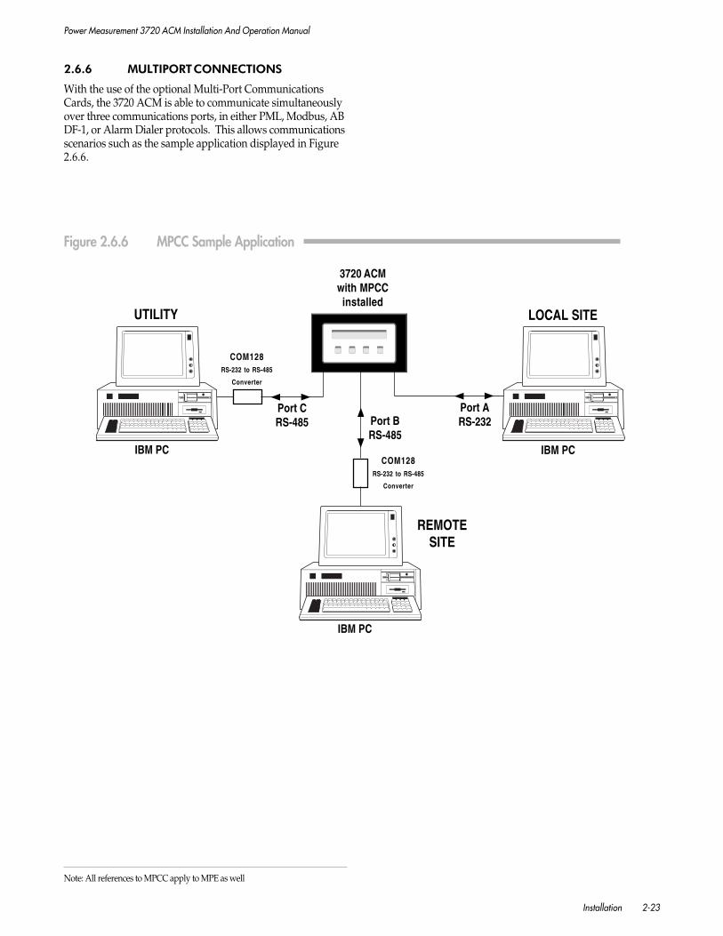
Power Measurement 3720 ACM Installation And Operation Manual
Installation 2-23
2.6.6 MULTIPORT CONNECTIONS
With the use of the optional Multi-Port CommunicationsCards, the 3720 ACM is able to communicate simultaneouslyover three communications ports, in either PML, Modbus, ABDF-1, or Alarm Dialer protocols. This allows communicationsscenarios such as the sample application displayed in Figure2.6.6.
3720 ACMwith MPCCinstalled
Figure 2.6.6 MPCC Sample Application
Port CRS-485 Port B
RS-485
Port ARS-232
COM128RS-232 to RS-485
Converter
COM128RS-232 to RS-485
Converter
LOCAL SITEUTILITY
IBM PC IBM PC
IBM PC
REMOTESITE
Note: All references to MPCC apply to MPE as well
Power Measurement 3720 ACM Installation And Operation Manual
2-24 Installation
2.7 CONTROL RELAY CONNECTIONS
This section describes the wiring connection requirements andapplications of the 3720 ACM on-board control relays.Section 3.7 describes the operation of the relays.
DANGER
Primary ProtectionThe relays of the 3720 ACM should not be used for primary protectionfunctions. These include applications where the device will be provid-ing:
a) Overcurrent protection on circuit breakers (I2t applications).
b) Protection of people from injury. If failure of the device can causeinjury or death, the 3720 ACM should not be used.
c) Energy limiting. If failure of the device will cause sufficient energyto be released that a fire is likely, the 3720 ACM should not beused. In electrical systems, energy limiting is normally providedby circuit breakers or fuses.
Secondary ProtectionThe 3720 ACM can be used for secondary protection functions. Secondary protectionincludes:
Situations where the 3720 ACM is backing up a primary protection device(shadow protection), such as an overcurrent relay.
Situations where the 3720 ACM is protecting equipment, not people. Thistypically includes applications such as over/under voltage, voltage unbalance,over/under frequency, reverse power flow, or phase reversal protection, etc.

Power Measurement 3720 ACM Installation And Operation Manual
Installation 2-25
N
N
R11 R12 R13 R21 R22 R23 R31 R32 R33
RX2RX1 RX3
N/CN/O
STATE RX1/RX2 RX2/RX3INACTIVE Open ClosedACTIVE Closed OpenPULSE Closed for Open for
duration of pulse duration of pulse
NOTES
1. Relays are Form C drycontact rated at 277 VAC or30 VDC @ 10 Amps.
2. Only relevant 3720 ACMterminal block connectionpoints are illustrated.
OPERATIONAL BLOCK DIAGRAMFOR ALL RELAYS
LOAD
LOAD
Normally OFF
Normally ON
RELAY CONTROLENABLE/DISABLE
10A FUSE120 VAC
CONTROL RELAYS
3720 ACM
Figure 2.7.2 Form-C Control Relay Connections
2.7.2 FORM-C RELAYS
The basic 3720 ACM provides 3 Form-C electromechanicalcontrol relays. These relays are rated for 277 VAC or 30 VDCat 10 Amps resistive load. Figure 2.7.2 illustrates the requiredconnections.
2.7.1 RELAY APPLICATION PRECAUTIONS
CAUTION
In applications where the relays are used toperform critical equipment control opera-tions (i.e. breaker trip, etc.), the importantprecautions described below should be fol-lowed.
1. Connection to the external equipment should be madevia an intermediate mechanism which allows relaycontrol to be completely disabled for commissioning andservicing (see Figure 2.7.2).
2. Following initial power up, the 3720 ACM should beprogrammed (see Chapter 3), including all requiredsetpoints for setpoint controlled relay operations (seeChapter 5).
3. The relay outputs of the 3720 ACM should be tested toensure that setpoint or manual control condition(s) areoccurring as expected.
4. Once correct relay operation has been verified, relaycontrol of the external equipment can be enabled.

Power Measurement 3720 ACM Installation And Operation Manual
2-26 Installation
NOTES
1. Relays are solid state rated at 24to 280 VAC @ 1 Amp.
2. Only relevant 3720 ACM terminalblock connection points areillustrated.
OPERATIONAL BLOCKDIAGRAM FOR ALL RELAYS
STATE RX2/RX3INACTIVE OpenACTIVE ClosedPULSE Closed for
duration of pulse
RX2N/C RX3
N/O
N/C R12 R13 N/C R22 R23 N/C R32 R33
1A FUSE24 to 280
VAC
CONTROL RELAYS - SOLID STATE OPTION
3720 ACM
N LOAD
Normally OFF
RELAY CONTROLENABLE/DISABLE
2.7.3 SOLID STATE RELAYS
The SSR option of the 3720 ACM provides three single-pole,single throw (SPST) solid state relays. These relays are ratedfor 24 to 280 VAC operation at 1 Amp AC resistive maxi-mum. The relays offer significantly longer lifetimes thanelectromechanical relays when used for continuous pulsingapplications.
Relay terminals RX2 and RX3 are used for each relay (where X= 1, 2, or 3). The RX1 terminal for each relay is left unused(no connection). See Figure 2.7.3.
IMPORTANT NOTE
USE AC VOLTAGES ONLY.
The relays are solid state and use zero-crossing turn on and off. This requiresthat they use AC voltages only.
Figure 2.7.3 Solid State Relay Option Connections
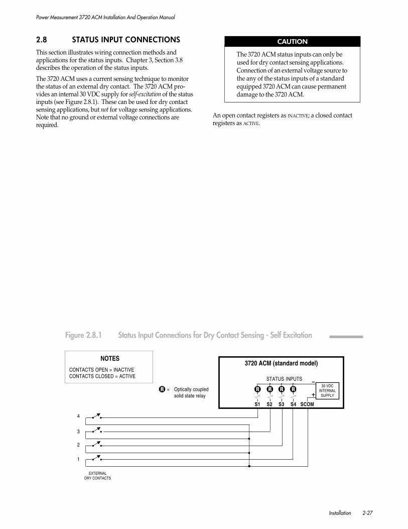
Power Measurement 3720 ACM Installation And Operation Manual
Installation 2-27
2.8 STATUS INPUT CONNECTIONS
This section illustrates wiring connection methods andapplications for the status inputs. Chapter 3, Section 3.8describes the operation of the status inputs.
The 3720 ACM uses a current sensing technique to monitorthe status of an external dry contact. The 3720 ACM pro-vides an internal 30 VDC supply for self-excitation of the statusinputs (see Figure 2.8.1). These can be used for dry contactsensing applications, but not for voltage sensing applications.Note that no ground or external voltage connections arerequired.
CAUTION
The 3720 ACM status inputs can only beused for dry contact sensing applications.Connection of an external voltage source tothe any of the status inputs of a standardequipped 3720 ACM can cause permanentdamage to the 3720 ACM.
An open contact registers as INACTIVE; a closed contactregisters as ACTIVE.
1
2
3
4
EXTERNALDRY CONTACTS
S1 S2 S3 S4 SCOM
30 VDCINTERNALSUPPLY
3720 ACM (standard model)
STATUS INPUTS
= Optically coupledsolid state relay
NOTES
CONTACTS OPEN = INACTIVECONTACTS CLOSED = ACTIVE
Figure 2.8.1 Status Input Connections for Dry Contact Sensing - Self Excitation

Power Measurement 3720 ACM Installation And Operation Manual
2-28 Installation
Figure 2.9.1 Auxiliary Voltage Input Connections
2.9 AUXILIARY VOLTAGE INPUTCONNECTIONS
Figure 2.9.1 illustrates a number of possible wiringconnection methods and applications for the VAUX input.Section 3.9 describes the operation of this input.
CAUTION
VAUX is a non-isolated input. If full isola-tion is required, use an intermediate isola-tion transducer.
Figure 2.10.1 Auxiliary Current Output Connections
TemperatureTransducerTemperature
ProbePower
VA
UX
NOTE
The resistors areselected to give anominal 1 V input toVAUX .
R1
R2
2.3 Kohm1 Watt
100 ohm1 Watt
24 VDCGenerator
StartBattery
+
-
VA
UX
NOTEMaximum 250 ohm load.
ChartRecorder
orRTU Input
0-20 mAor
4-20 mAinput
IOUT
0-20 mADC Meter
IOUT
APPLICATION #2
Output to an Analog Meter
APPLICATION #1
Output to a Chart Recorder or RTU Input
APPLICATION #1
Temperature Sensing
APPLICATION #2
Battery Voltage Sensing

Power Measurement 3720 ACM Installation And Operation Manual
Installation 2-29
2.10 AUXILIARY CURRENT OUTPUTCONNECTIONS
Figure 2.10.1 illustrates a number of possible wiring connec-tion methods and applications for the IOUT output. Section3.10 describes the operation of this output.
CAUTION
IOUT is a non-isolated input. If full isola-tion is required, use an intermediate isola-tion transducer.
2.11 MAINTENANCE
The following two circumstances describe the only regularmaintenance that the 3720 ACM may require.
2.11.1 BATTERY REPLACEMENT
The 3720 ACM non-volatile memory (NVRAM) and real-timeclock (RTC) circuit contain integrated battery backup systems.
NVRAMThe rated life of the NVRAM battery is seventy years at 50oC(122oF), 28 years at 60oC (140oF), and 11 years at 70oC(158oF). If the unit operates at less than 50oC for 60% of thetime, less than 60oC for 90% of the time, and less than 70oCfor 100% of the time, the expected life of the NVRAM batteryis 35 years. If the meter is operating in an environment wherethe temperatures regularly exceed 60oC, the NVRAM shouldbe replaced every ten years.
REAL-TIME CLOCKThe battery system for the RTC may exhibit a somewhatshorter lifespan than the NVRAM backup, due to the factthat it remains active (i.e. the clock continues to run) whenthe meter is unpowered.
BATTERY CHECKThe present condition of the NVRAM and real-time clockbatteries can be checked from the front panel of the 3720ACM by viewing the extended diagnostics parameters. See Section4.6 for instructions. If remaining battery life is 10% or less,the NVRAM should be replaced.
Contact POWER MEASUREMENT or your local representative forinformation on replacement procedures.
NOTE
When the NVRAM is replaced, historicdata may be lost. We recommend backingup critical logged data to the hard drive ofa computer prior to servicing. Setup pa-rameters and calibration of the unit are notaffected.
2.11.2 DISPLAY RESTORE
The 3720 ACM front panel display is a vacuum-fluorescenttype which exhibits high visibility due to its exceptionalbrightness. Due to a natural buildup of internal residues, thebrightness of individual segments may become degraded overextended periods when the display is not in use (i.e. when theDISPLAY TIMEOUT feature is used).
The brightness and consistency of all display segments can besimply restored as follows:
1. Enter programming mode and set the DISPLAY RESTORE
parameter (under DISPLAY) to YES.
2. Return to display mode. All segments of all characters inthe display are lit.
3. Leave the display in this mode for an extended period oftime. 24 to 48 hours is recommended.
4. Press any button on the front panel to return to normaldisplay mode.

Power Measurement 3720 ACM Installation And Operation Manual
2-30 Installation
DANGER
PT secondary circuits are capable ofgenerating lethal voltages and currentswith their primary circuit energized.Standard safety precautions should befollowed while performing anyinstallation or service on the device(i.e. removing PT fuses, etc.)
DANGER
CT secondary circuits are capable ofgenerating lethal voltages andcurrents when open circuited withtheir primary circuit energized.Standard safety precautions shouldbe followed while performing anyinstallation or service on the device(i.e. shorting CT secondaries, etc.)
2.12 FIELD SERVICE CONSIDERATIONS
In the unlikely event that the 3720 ACM unit should fail,servicing requires disconnection and removal of the unit fromits mounting for the purpose of repair, or for exchange with areplacement unit. The initial installation should be done in away which makes this as convenient as possible:
1. All phase voltage sense leads should be protected bybreakers or fuses at their source such that the 3720 ACMcan be safely disconnected.
2. A CT shorting block should be provided so that the 3720ACM current inputs can be safely disconnected withoutopen circuiting the CT’s. The shorting block should bewired so that protective relaying is not affected.
3. All wiring should be routed to allow easy removal of theconnections to the 3720 ACM terminal strips, the 3720ACM rear cover, and the 3720 ACM itself.
4. If the control relays are used, there should be a bypassmechanism installed (see Section 2.7).
Refer all questions regarding proper working procedures toqualified personnel.

Power Measurement 3720 ACM Installation and Operation Manual
General Operation 3-1
3 GENERAL OPERATION
3.1 INTRODUCTION
This chapter describes the following:
• Power up procedure.
• Front panel operation, included instructions fordisplaying real-time data and for performing fieldprogramming.
• Basic device setup procedure.
• Basic hardware operation, including descriptions ofthe relays, status inputs, and auxiliary input andoutput.
For a complete and detailed list of all measured parameters(not including TOU) and status information provided by the3720 ACM, refer to Chapter 4.
Chapter 5 describes the Time-Of-Use (TOU) system.
Chapters 6 to 8 describe the setup and operation of theadvanced features of the 3720 ACM, including setpoint,waveform and logging functions.
Remote communications setup and operation are described inChapter 9.
NOTE
The TRAN model provides no front paneldisplay or keypad. Data is read, and fieldprogramming performed, via the device’scommunications port. Refer to Chapter 8for instructions regarding TRAN operation.For the TRAN model, disregard all refer-ences made to front panel operations inChapter 3.
3.2 POWER UP
After all installation wiring is complete and has been doublechecked, the unit may be powered up by applying theappropriate voltage to the POWER input terminals.
The 3720 ACM first enters its display mode, presenting Volts-Phase-Amps-Power Function. The power function displayedon power-up is kW average, totalled for all phases.
The values initially appearing may not be correct, since theunit has not yet been told a number of necessary pieces ofinformation about the installation. The process of giving the3720 ACM this information is known as field programming.
The 3720 ACM display mode and field programming modeare each described in detail in the following sections.
3.3 DISPLAY MODE
3.3.1 FRONT PANEL DISPLAY
Data Display and FormatsThe 3720 ACM provides a unique and very flexible userinterface. The front panel features a large, high-visibility, 20-character vacuum fluorescent display. The display canpresent a wide variety of information in many differentformats. The user can also customize the display by definingwhich measured parameters can be accessed and in whatformat they are displayed. The following information andformats can be displayed:
BASIC PHASE DISPLAYThe basic front panel display (on power-up) presentsVOLTS, AMPS and POWER FUNCTIONS for the selected PHASE
(f) (Figure 3.3.1a). The PHASE button is used to advancethrough each phase in sequence, while a selection ofpower functions can be accessed using the FUNCTION
button. The format of the phase labels and numericreadings can be programmed to conform to worldconventions (see Section 3.6).
FULL WIDTH DISPLAYSVery large measured values (i.e. kW Hours) and param-eters with large display labels are presented using theentire display (Figure 3.3.1b).
NOTE
While viewing a full-width display, pressthe PHASE button to return to the standardVolts-Phase-Amps display.
3-PHASE DISPLAYSConcurrent display of readings for all three voltage orcurrent phases is possible (Figure 3.3.1c). The GROUP
buttons can be programmed to access these displays (seeSection 3.3.2).
STATUS INFORMATIONStatus information includes the present condition of thethree relays, four digital (status) inputs, and seventeensetpoints. The GROUP buttons can be programmed toaccess all status information (see Section 3.2.2). Displaylabels for relay and status input conditions are userdefinable via communications (Figures 3.3.1d and e). Forexample, the two possible conditions of a setpoint-controlled relay could be displayed as “BREAKER NORMAL”and “OVER CURRENT TRIP”. Device programming isdescribed in Section 3.4

Power Measurement 3720 ACM Installation and Operation Manual
3-2 General Operation
Display LabelsThe wide range of measured parameters and statusinformation provided by the 3720 ACM requires thatspecial parameter name formats be used on the frontpanel. These labels are also used to identify parametertypes selected by the user in programming mode.
Figure 3.3.1f lists the display labels used by the 3720 ACMto identify various measurement modes and status info-rmation. These labels are further described in Chapter 4.
Display ResolutionThe 3720 ACM front panel can display readings with upto 9 digits of resolution. Decimal resolutions depend onthe parameter being displayed.
• Most measured parameter readings are displayedin integer format, using no decimal places.
• Harmonic Distortion readings are displayed withone decimal place of resolution.
• Frequency readings are displayed with two decimalplaces of resolution.
• Status Input Counter totals can be displayed withbetween 0 and 3 decimal places of resolutiondependent on the user-definable RESOLUTION
parameter (see Section 3.8).
Display TimeoutThe life and brightness of the 3720 ACM vacuumfluorescent display can be significantly extended byreducing the on time. The 3720 ACM provides a DISPLAY
TIMEOUT parameter that can be used to set a timeoutinterval of 1 to 999 minutes, after which the displayautomatically switches to display-saver mode (“PML” scrollingacross the display). This interval starts counting downfrom the last button press made on the front panel. Atimeout interval of 180 minutes (3 hours) or less isrecommended. Setting the parameter to zero causes thedisplay to stay on indefinitely. While the display isturned off, pressing any button on the front panel turns itback on again. Device programming is described inSection 3.4.
a) Standard Phase Display
b) Full Width Displays (ex. kW, phase A, therm. demand, max.)
c) 3 Phase Displays
VOLTS AMPS POWER FUNCTIONSRMS RMS
Figure 3.3.1 Front Panel Display Examples
d) Status Information (Example: Status Input Condition)
e) Status Information (Example: Setpoint Condition)
VOLTS AMPS POWER FUNCTIONSRMS RMS
VOLTS AMPS POWER FUNCTIONSRMS RMS
f) Display Labels for Measured Parameter Modes &Status Information
Note: Display labels for relay and status input information(example [d] above) are user definable.
Real Time
Total Harmonic Distortion
Total Even Harmonic Distortion
Total Odd Harmonic Distortion
Individual Harmonic Distortion (example is HD15)
Thermal Demand
Sliding Window Demand
Predicted S.W. Demand
Minimum
Maximum
Imported (energy)
Exported (energy)
Net (difference between imported and exported)
Total (total of imported and exported)
Relay Output (example is R3)
Status Input (example is S4)
High-Speed Setpoint (example is HS6)
Standard Setpoint (example is SP11)
Time-Of-Use (registers, tariffs, etc.)
Time-Overcurrent Curve
High-Speed Snapshot Log
VOLTS AMPS POWER FUNCTIONSRMS RMS
VOLTS AMPS POWER FUNCTIONSRMS RMS

Power Measurement 3720 ACM Installation and Operation Manual
General Operation 3-3
3.3.2 FRONT PANEL BUTTONS
The 3720 ACM uses four long-life, stainless steel membraneswitches for parameter selection and programming functions.(See figure 3.3.2)
Phase ButtonIf you are viewing the standard display, the PHASE buttonadvances through each phase. The sequence of phasereadings depends on the device setup, including the VOLTS
MODE and PHASE ROTATION selected. Device setup is describedin Section 3.4 The phase field of the front panel displayindicates the phase for which readings are being displayed.
The following phase labels are used:
These labels indicate line-to-neutral values are beingdisplayed for the indicated phase.
Phase indicators displayed with a comma indicate line-to-line values are being displayed for the indicated phase.
An asterisk symbol indicates that the average for all line-to-neutral or line-to-line phases is being displayed.
A quotation mark after a value (measurement) indicatesa CT/PT secondary measurement.
41 32
87
6
5
7 & 8 GROUP1 + GROUP2 together = enter programming mode or return to display mode
1. 4-digit VOLTS display
2. PHASE indicator
3. 4-digit AMPS display
4. 5-digit / 8-character POWER FUNCTION display
5. Top button labels indicate display mode functions
6. Bottom button labels indicate programming mode functions
Figure 3.3.2 3720 ACM Front Panel Features

Power Measurement 3720 ACM Installation and Operation Manual
3-4 General Operation
The following phases of readings are available in each mode:
VOLTS MODE = 4W-WYE, 3W-WYE, OR DEMO.For each of these modes, the PHASE button advancesthrough:
• line-to-neutral average of the three phases
• line-to-neutral values for each phase
• line-to-line average of the three phases
• line-to-line values for each phase
VOLTS MODE = DELTAThe PHASE button advances through:
• line-to-line average of the three phases
• line-to-line values for each phase
VOLTS MODE = SINGLEThe PHASE button advances through:
• line-to-neutral average of the two phases
• line-to-neutral values for each phase and the line-to-line value
The PHASE button also advances the display through eachrelay (R1 to R3), digital status input (S1 to S4), or setpoint(S01 to S11, H01 to H06) when status conditions are beingdisplayed.
Auto Phase Cycling ModeYou can make the 3720 ACM automatically cycle the displaythrough each phase by holding down the PHASE button formore than 4 seconds, then releasing. The display advancesthrough each phase (A, B etc.) at 4 second intervals, display-ing the volts and amps for each phase. Pressing any buttonreturns the display to the regular non-cycling viewing mode.
Function ButtonA preset list of useful power function parameters is availablevia the FUNCTION button. Press the FUNCTION button toadvance through each measured parameter.
For per phase values displayed using the FUNCTION button,the PHASE button can be used to advance the display througheach phase.
The following is the complete sequence of power functionparameters accessible using the FUNCTION button:
• kW per phase
• kVAR per phase
• kVA per phase
• Power Factor per phase
• Current I4
• Frequency (phase A)
• Voltage Vaux
• kWH Import (total for all 3 phases)
• kWH Export (total for all 3 phases)
• kVARH Import (total for all 3 phases)
• kVARH Export (total for all 3 phases)
• kVAH Net (total for all 3 phases)
A full description of each parameter is provided in Chapter 4.
Auto Function Cycling ModeYou can make the 3720 ACM automatically cycle the displaythrough each power function on the front panel display. Thepower functions displayed are the group of parametersnormally displayed using the FUNCTION button (kW, kVAR,etc.) To start the cycling mode, hold down the FUNCTION
button for more than 4 seconds, then release. The display willadvance through each power function at 4 second intervals.Pressing any button will return the display to the regular non-cycling viewing mode.
Group ButtonsYou can use the GROUP1 and GROUP2 buttons to displayadditional groups of measurements and status information.The parameters accessible using each GROUP button are user-definable. Up to 18 parameters may be assigned to eachbutton. Similar to the FUNCTION button, each press of a GROUP
button will advance the display through the list of itemsassigned to that button.
The GROUP buttons are ideal for creating convenient customgroupings of important parameters for quick viewing. Forexample, the user might wish to assign the third and fifthharmonic distortion values for each input to the GROUP1button and relay status information to the GROUP2 button.Any of the measured and status parameters can be assignedto either GROUP button. Programming the GROUP buttonsmust be performed via communications.

Power Measurement 3720 ACM Installation and Operation Manual
General Operation 3-5
For per phase parameters displayed using the GROUP buttons,the PHASE button can be used to advance the display througheach phase. For relay, status input, and setpoint conditions,the PHASE button can be used to advance through each relay,status input or setpoint number. The MODE function can alsobe used to display additional related parameters, if applicable.This is described later in this section.
The following default parameters have been assigned to eachGROUP button.
GROUP 1:• 3-phase Voltage line-to-neutral (if applicable)
• 3-phase Voltage line-to-line
• 3-phase Current
• Voltage line-to-neutral Maximum per phase(if applicable)
• Voltage line-to-line Maximum per phase
• Current Maximum per phase
• kW Maximum per phase
• kVAR Maximum per phase
• Frequency Maximum (phase A)
• Power Factor Minimum per phase
• Power Factor Maximum per phase
• Frequency Minimum (phase A)
• Voltage line-to-neutral Minimum per phase
• Voltage line-to-line Minimum per phase
• Relay Condition (1 to 3)
• Status Input Condition (1 to 4)
GROUP 2:• Voltage THD (total harmonic distortion)
per phase
• Current THD per phase
• Voltage THD Maximum per phase
• Current THD Maximum per phase
• Current 3rd HD (harmonic distortion) per phase
• Current 5th HD per phase
• Current 7th HD per phase
• Current Sliding Window DemandMaximum average of all phases
• kW Sliding Window DemandMaximum total of all phases
• kVAR Sliding Window DemandMaximum total of all phases
• kVA Sliding Window DemandMaximum total of all phases
A full description of each parameter is provided in Chapter 4.
Mode FunctionAs an added convenience feature, a special MODE function hasbeen provided for use with parameters assigned to theGROUP1 or GROUP2 button.
The MODE function provides quick access to additionalmeasurement modes for the parameter currently beingdisplayed, if applicable. For power and harmonic distortionparameters, this can include demand and minima/maxima.For example, if the front panel display is presenting a kWmeasurement, the MODE function can be used to advance thedisplay through kW Min, kW Max, kW Thermal Demand, kWThermal Demand Min, and kW Thermal Demand Max. Thesequence of parameters displayed is definable by the user viacommunications.
The MODE function can also be used to advance through all bi-directional modes of an energy parameter. This can includeimport, export, net, and total measurements.
The MODE function is accessed using a special button combi-nation on the front panel:
1. First, press either GROUP button to display the desiredparameter.
2. Press and hold down either GROUP button.
3. With the GROUP button held down, press the FUNCTION
button.
4. Release the FUNCTION button.
5. With the GROUP button still held down, pressing theFUNCTION button will advance through each availablemode.
6. To return the front panel buttons back to normaloperation, first release the GROUP button, then press theFUNCTION button once more.
NOTE
If a particular parameter accessed using aGROUP button has not been programmed toprovide additional modes, the MODE func-tion has no effect.

Power Measurement 3720 ACM Installation and Operation Manual
3-6 General Operation
3.4 FIELD PROGRAMMING
3.4.1 INTRODUCTION
Basic device programming can be performed quickly andeasily from the front panel, or via the communications portusing a portable or remotely located computer. Basic setupparameters include scaling factors for the voltage and currentinputs, voltage mode (wye, delta, etc.), and communicationssettings.
Advanced features including waveform capture, waveformrecording, data logging, setpoint and relay control functions,and customization of the front panel display and GROUP
buttons are programmable via the communications port only.POWER MEASUREMENT’s PC-based SCADA software fullysupports 3720 ACM programming, providing a number ofparameter screens which make setup quick and easy. Theopen communications protocol of the 3720 ACM also allowsfree access to all programming parameters using any compat-ible third-party system.
Setup and other critical information are saved when power isturned off. All programming is password protected.
A complete list of all programmable setup parameters isprovided in Section 3.4.6.
This manual describes procedures for programming the 3720ACM from its front panel only. For information on program-ming via communications using the SCADA software, refer tothe SCADA Software Installation and Operation Manual.
3.4.2 ENTERING PROGRAMMING MODE
To program the setup parameters of the 3720 ACM from thefront panel, you must first enter programming mode. To enterprogramming mode, press the two GROUP buttons together.When programming mode is first entered, ‘PROGRAMMING
MODE’ is displayed.
You can return to display mode at any time by again pressingthe two GROUP buttons together.
3.4.3 PROGRAMMING BUTTON FUNCTIONS
In programming mode, the buttons of the front panel take onnew programming functions. The label below each buttonindicates its alternate function.
• PARAMETER SELECT
Selects which parameter is displayed.
• CURSOR
Moves the cursor left one digit. The cursor positionwraps around to the right of the number if advancedpast the left-most digit.
• INCREMENT
Increments the digit under the cursor, advancesthrough a number of preset values, or toggles a YES/NO
option.
• DECREMENT
Decrements the digit under the cursor, advancesthrough a number of preset values in reverse order, ortoggles a YES/NO option.
3.4.4 ENTERING AND CHANGING THEPASSWORD
Pressing the PARAMETER SELECT button once advances past the‘PROGRAMMING MODE’ display to the first programming modeparameter, the PASSWORD. When the 3720 ACM is shipped,the PASSWORD is 0. The correct PASSWORD must be entered ifany parameter values are to be changed. If the password isnot entered, setup parameter values may still be viewed, butnot modified.
To change the password, the present password must first beentered. To change the password the PARAMETER SELECT
button should be pressed repeatedly to advance past allparameters until the password parameter is displayed again.This time the new password should be entered. Once this hasbeen done, returning to display mode changes the password.
3.4.5 ACCESSING AND MODIFYINGPARAMETERS
Parameter GroupsTo support the extensive functionality and flexibility that the3720 ACM offers, a large number of user-programmableparameters are provided. To make field programming asefficient as possible, the parameters accessible via the frontpanel have been organized into 6 groups:
• Basic System Setup
• Auxiliary Setup
• Clear Functions
• Communications
• Front Panel Display
• Diagnostics
Each parameter group provides an access parameter. The defaultsetting for all group access parameters is NO. If the value isnot changed, pressing the PARAMETER SELECT button skips overthat parameter group. If the value is set to YES, the PARAMETER
SELECT button advances through each parameter within thatgroup.
Advancing past all parameters within a group returns you tothe access parameter for that group, with its value set to NO.You can then skip to the next group by pressing PARAMETER
SELECT or gain access once more to the same group by settingthe parameter to YES.
The entire parameter list wraps around. If a parameter groupis missed, the PARAMETER SELECT button may be pressedrepeatedly to return to the desired group.

Power Measurement 3720 ACM Installation and Operation Manual
General Operation 3-7
Defining New Parameter ValuesIf the correct password was entered, you can modify anysetup parameter. As discussed in Section 3.4.3, the CURSOR,INCREMENT and DECREMENT buttons can be used to changeindividual digits or select from a preset list of options for thatparameter value. Section 3.4.6 lists all programmable param-eters and their range of possible values.
If you attempt to set a parameter to a value outside of itsallowed range, the display flashes the message ‘INVALID
ENTRY’. The message remains on the display until any buttonis pressed. The parameter is shown again with its previousvalue.
Parameter modifications are implemented immediately whenyou advance to the next parameter.
Returning to Display ModeOnce all parameters have been set to their desired values,pressing the two GROUP buttons together returns to displaymode.
Programming ExampleFigure 3.4.5 gives a step-by-step example of how to programthree operating parameters from the front panel. The examplegiven shows how to set the VOLTS MODE to DELTA the VOLTS
SCALE to 277 and the AMPS SCALE to 2000.
STEP ACTION: DISPLAY READS:
1. Press the GROUP buttons together to enter programming mode. PROGRAMMING MODE
2. Press PARAMETER SELECT button once. PASSWORD= ****
3. Enter password by using INCREMENT and CURSOR buttons.To set to 0 (the default), press INCREMENT button once. PASSWORD= ***0
4. Press PARAMETER SELECT once. SYSTEM SETUP= NO
5. Press INCREMENT once to allow access to this parameter group. SYSTEM SETUP= YES
6. Press PARAMETER SELECT to advance to next parameter. VOLTS MODE= 4W-WYE
7. Press INCREMENT to advance to next parameter value. VOLTS MODE= DELTA
8. Press PARAMETER SELECT to advance to next parameter. VOLTS SCALE= 1200
9. Enter new value (277) for VOLTS SCALE.Set far right digit to 7 by pressing INCREMENT until display reads: VOLTS SCALE= 1207
10. Move cursor one digit left by pressing CURSOR button once. VOLTS SCALE= 1207
11. Set next digit to 7 by pressing INCREMENT until display reads: VOLTS SCALE= 1277
12. Move cursor 2 digits left by pressing CURSOR button twice. VOLTS SCALE= 1277
13. Set last digit to 0 by pressing DECREMENT once: VOLTS SCALE= 0277
14. Press PARAMETER SELECT to advance to next parameter AMPS SCALE= 5000
15. Enter new value (2000) for AMPS SCALE.Move cursor three digits left by pressing CURSOR button three times. AMPS SCALE= 5000
16. Set digit to 2 by pressing DECREMENT three times: AMPS SCALE= 2000
17. Press the GROUP buttons together to return to display mode. Volts, Phase, Amps, Function
Figure 3.4.5 Field Programming Example
NOTE: Cursor position in the example is shown as an underscore line. In theactual front panel display, cursor position is indicated by a blinking character.
3.4.6 OPERATING PARAMETERDESCRIPTIONS
Figures 3.4.6a to 3.4.6d provide a brief description of eachoperating parameter that may be programmed from the frontpanel. Figures 3.4.6e to 3.4.6l list all additional operatingparameters which are only accessible via communications.
More detailed descriptions of each operating parameter areprovided throughout this manual where operational featuresare described.

Power Measurement 3720 ACM Installation and Operation Manual
3-8 General Operation
Figure 3.4.6a Programmable Operating Parameters I
... continuedPressing PARAMETER SELECT returns to system setup parameter.
VOLTS MODE Defines the power system configuration. 4W-WYE • DELTA • SINGLE • DEMO • 3W-WYE
VOLTS SCALE Defines the full-scale input reading (in Volts) for thephase A, B and C voltage inputs.
0 to 999,999
AMPS SCALE Defines the full-scale input reading (in Amps) for thephase A, B and C current inputs (CT primary currentrating).
STANDARD FREQ Defines the line frequency the 3720 ACM is to monitor(in Hertz).
50 • 60
POS • NEG
0 to 30,000
PHASE ROTATION Defines the normal phase sequence used for PFpolarity detection in delta mode, and for the phasereversal detection setpoint. See Chapter 5 for setpointoperation.
NUM DEMAND PERIOD Defines the number of demand periods to be averagedin calculating all sliding window demands.
1 to 15
EXAMPLES Direct Connect (Wye)System Configuration: 120 VAC line-neutral/208 VAC line-line 277 VAC line-neutral/480 VAC line-line 347 VAC line-neutral/600 VAC line-line Using PTs
Set VOLTS SCALE to: 120 277 347 PT primary rating
I4 SCALE 0 to 9,999Defines the full-scale current reading (in Amps) for theI4 (neutral/ground) input.
1 to 99 (default = 5%) • 0 = offDefines the base (in % of dmd. period) for predicteddemand. Lower % = faster prediction.
PREDICT DMD BASE
DEMAND PERIOD Defines the length of the demand period (in minutes)used in calculating all sliding window demand values.
1 to 99 • 0 = off
DEMAND SYN Defines the method of demand synchronization.INTERNAL synchronizes to the onboard clock.EXTERNAL synchronizes to the S4 pulse.
INTERNAL • EXTERNAL
THERMAL PERIOD Sets the time (in minutes) it takes the demand to reach90% of the thermal constant for thermal demandmeasurements.
2 to 99 • 0 or 1 = off
NOTE: Refer to Section 3.5 for more information on setting the following parameters.
SYSTEM SETUP Allows access to this group of parameters. SelectingNO (default) will advance to the next group.
NO • YES
BASIC SYSTEM SETUP GROUP
4-digit numberPASSWORD Correct password must be entered to allow setupparameters to be modified or clear (reset) functions tobe executed. Also used to redefine password. SeeSection 3.4.4.
Part I: Front Panel or Communications Access
Parameter Description Range/Options
Initial display upon entering programming mode. PressPARAMETER SELECT to advance through each parameter.
PROGRAMMING MODE
Only if not password protected.See pages 3-10, 3-11.
CLEAR MAX/MIN

Power Measurement 3720 ACM Installation and Operation Manual
General Operation 3-9
... continued
Figure 3.4.6b Programmable Operating Parameters I
parameters. Selecting NO (default) will advance to thenext group.
NO • YESAllows access to this group of
Defines the reading for a full-scale (1.000 VAC) aux.voltage input. See Section 3.9.
0 to 999,999VAUX SCALE
VAUX ZERO Defines the reading for a zero-scale (0.000 VAC) aux.voltage input. To define a negative number, toggle the7th (i.e. most significant) digit.
-999,999 to 999,999
I OUT SCALE Defines the reading of the associated parameter corre-sponding to a full-scale auxiliary current output. SeeSection 3.10. (Note: Frequency values must be enteredx100. Example: 60 Hz = 6000)
0 to 999,999
AUXILIARY SETUP GROUPAUXILIARY SETUP
IOUT ZERO -999,999 to 999,999
I OUT KEY Defines the measured parameter to which the currentoutput will be proportional.
VOLTAGE A • VOLTAGE B • VOLTAGE C •VOLTAGE AV •CURRENT A • CURRENT B • CURRENT C •CURRENT AV • CURRENT I4kW A • kW B • kW C • kVAR A • kVAR B • kVAR C •kVA A • kVA B • kVA C •kW TOTAL • kVAR TOTAL • kVA TOTAL •PF TOTAL •SD PARAMETER #1* • SD PARAMETER #2* •FREQUENCY • VAUX
I OUT RANGE 0-20mA • 4-20mA
Part I: Front Panel or Communications Access
Parameter Description Range/Options
Defines the reading of the associated parameter corre-sponding to a zero-scale auxiliary current output. Todefine a negative number, toggle the 7th (i.e. most-significant) digit.
Defines the output range for the auxiliary current output.
*Note: SD parameters listed are the first 2in the list of sliding window demandparameters defined by the user.
Pressing PARAMETER SELECT returns to the AUXILIARY SETUP parameter

Power Measurement 3720 ACM Installation and Operation Manual
3-10 General Operation
Figure 3.4.6c Programmable Operating Parameters I
CLEAR FUNCTIONS GROUP
CLEAR FUNCTIONS Allows access to this group of parameters. SelectingNO (default) will advance to the next group.
NO • YES
Part I: Front Panel or Communications Access
Parameter Description Range/Options
Pressing PARAMETER SELECT returns to the CLEAR FUNCTIONS parameter.
CLEAR STATUS COUNT 0 (none) • 1 • 2 • 3 • 4 • ALLSelected status input counter total(s) are cleared whenPARAMETER SELECT is pressed.
CLEAR HOURS? Selecting YES resets kWH, kVARH, and kVAHcounters to zero when PARAMETER SELECT is pressed.Note: T.O.U. energy registers are not affected.
NO • YES
CLEAR MAX/MIN? Selecting YES resets the Preset and all Program-mable Max/Min Logs when PARAMETER SELECT ispressed.
NO • YES
UNIT ID Defines the communications identification (ID) numberfor the 3720 ACM.
1 to 9999 for PML 3720 protocol1 to 247 for Modbus protocol1 to 99 for AB DF-1 protocol
NO • YESProvides access to the configuration parameters forthe PML 3720 protocol.
CONFIG PML 3720(ISOCOM ONLY)
CONFIG MODBUS(ISOCOM ONLY)
Provides access to the configuration parameters forthe Modbus protocol.
NO • YES
PROTOCOL PML 3720 • MODBUS • NONE • AB DF-1 (MPCC ONLY),PML 3720 AD (MPCC ONLY)
Defines the active protocol. Selecting NONEdisables the port.
REGISTER SIZE Specifies if registers are 16 or 32 bit. The default is16B. (This parameter only appears for Modbussetup.)
16B • 32B
BAUD RATE Defines the baud rate. 300 • 1200 • 2400 • 4800 • 9600 • 19200MPCC ONLY: 38400 • 57600 • 115200
COMMUNICATIONS NO • YES
COMM CARD ISOCOM 2 • MULTIPORT
COMM PORT ACOMM PORT B*COMM PORT C**Ports B & C - MPCC only
NO • YES
Allows access to this group of parameters. SelectingNO (default) will advance to the next group.
Identifies the communication card installed.
These three parameters permit access to the setupmenus of each communication port. The communi-cation parameters that follow can be set independ-ently for each port.
COMMUNICATIONS GROUP
COMM MODE(ISOCOM ONLY)
View comm. mode (set by jumper block on comm.card. See Chapter 2, Sect. 2.6.2)
RS-232 • RS-485
... continued
Note: All references to MPCC apply to MPE as well

Power Measurement 3720 ACM Installation and Operation Manual
General Operation 3-11
Figure 3.4.6d Programmable Operating Parameters I
TRANSMIT DELAY Sets the delay between asserting RTS and thetransmission of the first bit.
0 to 999 ms
Pressing PARAMETER SELECT returns to the COMMUNICATIONS parameter.
DISPLAY Allows access to this group of parameters. SelectingNO (default) will advance to the next group.
NO • YES
Duration (in minutes) between last button press andentering display-saver mode.
0 (stay on) • 1 to 999 (minutes)DISPLAY TIMEOUT
Defines numeric format. 1,234.5 is default. 1,234.5 • 1234,5FORMAT
PHASE LABEL Defines the phase label format. ABC • XYZ • RYB • RST
RESTORE DISPLAY Used to restore front panel display brightness.Selecting YES lights all segments of display uponexit from programming mode. See Section 3.6.
NO • YES
VOLTS Selects primary or secondary volts display. PRIMARY • SECONDARY
AMPS Selects primary or secondary amps display. PRIMARY • SECONDARY
PROTECT MIN/MAX Enables password protection on clearing of MAX/MIN.
YES • NO
Allows access to this group of parameters.Selecting NO (default) returns to PASSWORD.
NO • YESDIAGNOSTICS
Firmware version currently installed.FIRMWARE VER WWW X.X.X.X WWW = standard or custom(V = standard)
X.X.X.X = version numberCARD REV(MPCC ONLY)
MPCC firmware version AS DIRECTLY ABOVE
Pressing PARAMETER SELECT returns to the DISPLAY parameter.
DIAGNOSTICS GROUP
EXTENDED NO • YES
CLEAR DIAG CODES Reset communications diagnostics. YES • NO
Pressing PARAMETER SELECT returns to the DIAGNOSTICS parameter.... continued
FRONT PANEL DISPLAY GROUP
Allows access to an extended group of diagnosticparameters using a special button combination fromdisplay mode. See Section 4.6 for instructions andlist of extended parameters.
Part I: Front Panel or Communications Access
Parameter Description Range/Options
RTS ACTIVE LVL Sets the active logic level asserted by the RTS linewhen using RS-232 communications (refer to Chapter9).
LOW • HIGH
US ACK/NAK Determines if the 3720 ACM will requestacknowledgement from master. The default is NO.(This parameter only appears for PML 3720 setup.)
NO • YES
INVALID OBJECTS Specifies if the 3720 ACM returns a value for an invalidobject. If set to YES, the invalid register will containeither 0 or 0xFFFF. (This parameter only appears forModbus setup.)
NO • YES
PASSWORD PROTECT Provides password protection for all configurations andrelay operations. Functionality depends on the commu-nications software used. The default is NO. (Note thatPOWER MEASUREMENT’s SCADA software requires thisto be set to NO.)
NO • YES
(ISOCOM ONLY)
Note: All references to MPCC apply to MPE as well

Power Measurement 3720 ACM Installation and Operation Manual
3-12 General Operation
Figure 3.4.6e Programmable Operating Parameters II
Part II: Communications Access Only
Parameter Description Range/Options
Selects one of the eleven standard setpoints to beprogrammed.
1 to 11STD SETPOINT
The following three parameters define the measured parameter:
STANDARD SETPOINTS SETUP
SLIDING WINDOW DEMAND SETUP
Only the additional demand setup parameters not available from the front panel of the 3720 ACM are listed here.
Selects one of ten sliding window demand measuredparameters to configure.
1 to 10SWD PARAMETER
Defines the type of measured parameter.NOT USED disables the selected parameter.
NOT USED •VOLTAGE LN •VOLTAGE LL • CURRENT •kW • kVA • kVAR • PF • FREQUENCY •THD • HD ODD • HD EVEN • HDxx (xx = 2 to 15) •K-FACTOR
PARAMETER TYPE
Selects the phase or input for the selected parametertype, if applicable.
A • B • C • AVG • TOT • I4 • VAUXINPUT
PREDICTED DEMAND BASE Sets the sensitivity of the demand prediction.Smaller value provides faster response. Default is5%. See Section 4.3.1.
0 (disable all) • 1 to 99
WAVEFORM RECORDER SETUP
WFR CONFIGURATION Configures storage for the Waveform Recorder.Option format = # of events x cycles/event.
3x12 • 2x18 • 1x36
Defines the type of parameter the selected setpoint isto monitor. A setting of NOT USED disables thesetpoint. See Chapter 6 for setpoint type descriptions.
NOT USED •OVER VOLTAGE LN •OVER VOLTAGE LL •UNDER VOLTAGE LN •UNDER VOLTAGE LL •VOLTAGE UNBALANCE •OVER CURRENT • UNDER CURRENT •CURRENT UNBALANCE • PHASE REVERSAL •OVER kW IMP • OVER kW EXP •OVER kVAR IMP • OVER kVAR EXP •OVER kVA • OVER kWD • OVER kVAD• OVER FREQ •UNDER FREQ • UNDER PF LAG • UNDER PF LEAD •STATUS x INACTIVE (x = 1 to 4) •STATUS x ACTIVE (x = 1 to 4) •ANY STATUS INACTIVE • ANY STATUS ACTIVE •OVER Sx COUNTER (x = 1 to 4) •OVER THD, OVER HD ODD • OVER HD EVEN •OVER HDxx (where xx = 2 to 15) • K-FACTOR •NEW HOUR • NEW DAY • NEW WEEK • NEW MONTH •NEW YEAR
PARAMETER TYPE
INPUT Selects the phase or input for the selected parametertype, if applicable.
A • B • C • AVERAGE • TOTAL • I4 • VAUX
... continued
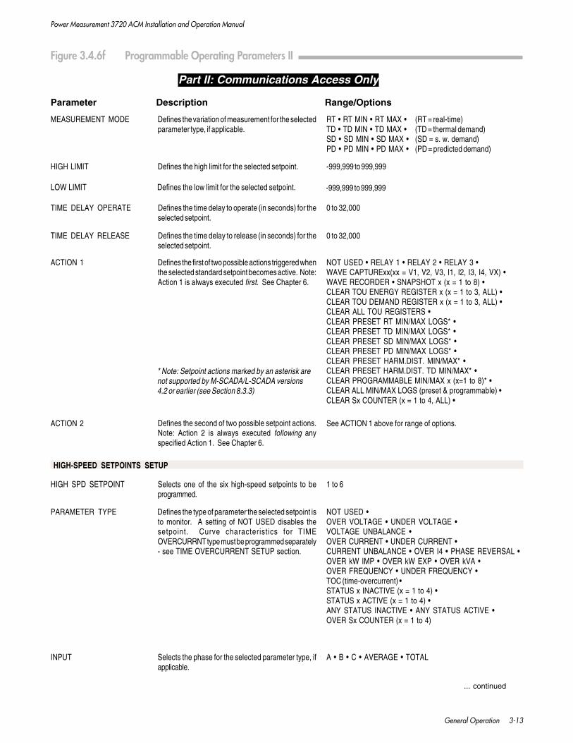
Power Measurement 3720 ACM Installation and Operation Manual
General Operation 3-13
Part II: Communications Access Only
Parameter Description Range/Options
Defines the variation of measurement for the selectedparameter type, if applicable.
MEASUREMENT MODE RT • RT MIN • RT MAX • (RT = real-time)TD • TD MIN • TD MAX • (TD = thermal demand)SD • SD MIN • SD MAX • (SD = s. w. demand)PD • PD MIN • PD MAX • (PD = predicted demand)
Defines the high limit for the selected setpoint.HIGH LIMIT -999,999 to 999,999
Defines the low limit for the selected setpoint.LOW LIMIT -999,999 to 999,999
TIME DELAY OPERATE Defines the time delay to operate (in seconds) for theselected setpoint.
0 to 32,000
TIME DELAY RELEASE Defines the time delay to release (in seconds) for theselected setpoint.
0 to 32,000
ACTION 1 Defines the first of two possible actions triggered whenthe selected standard setpoint becomes active. Note:Action 1 is always executed first. See Chapter 6.
NOT USED • RELAY 1 • RELAY 2 • RELAY 3 •WAVE CAPTURExx(xx = V1, V2, V3, I1, I2, I3, I4, VX) •WAVE RECORDER • SNAPSHOT x (x = 1 to 8) •CLEAR TOU ENERGY REGISTER x (x = 1 to 3, ALL) •CLEAR TOU DEMAND REGISTER x (x = 1 to 3, ALL) •CLEAR ALL TOU REGISTERS •CLEAR PRESET RT MIN/MAX LOGS* •CLEAR PRESET TD MIN/MAX LOGS* •CLEAR PRESET SD MIN/MAX LOGS* •CLEAR PRESET PD MIN/MAX LOGS* •CLEAR PRESET HARM.DIST. MIN/MAX* •CLEAR PRESET HARM.DIST. TD MIN/MAX* •CLEAR PROGRAMMABLE MIN/MAX x (x=1 to 8)* •CLEAR ALL MIN/MAX LOGS (preset & programmable) •CLEAR Sx COUNTER (x = 1 to 4, ALL) •
* Note: Setpoint actions marked by an asterisk arenot supported by M-SCADA/L-SCADA versions4.2 or earlier (see Section 8.3.3)
Defines the second of two possible setpoint actions.Note: Action 2 is always executed following anyspecified Action 1. See Chapter 6.
See ACTION 1 above for range of options.ACTION 2
PARAMETER TYPE Defines the type of parameter the selected setpoint isto monitor. A setting of NOT USED disables thesetpoint. Curve characteristics for TIMEOVERCURRNT type must be programmed separately- see TIME OVERCURRENT SETUP section.
NOT USED •OVER VOLTAGE • UNDER VOLTAGE •VOLTAGE UNBALANCE •OVER CURRENT • UNDER CURRENT •CURRENT UNBALANCE • OVER I4 • PHASE REVERSAL •OVER kW IMP • OVER kW EXP • OVER kVA •OVER FREQUENCY • UNDER FREQUENCY •TOC (time-overcurrent) •STATUS x INACTIVE (x = 1 to 4) •STATUS x ACTIVE (x = 1 to 4) •ANY STATUS INACTIVE • ANY STATUS ACTIVE •OVER Sx COUNTER (x = 1 to 4)
HIGH SPD SETPOINT Selects one of the six high-speed setpoints to beprogrammed.
1 to 6
HIGH-SPEED SETPOINTS SETUP
Figure 3.4.6f Programmable Operating Parameters II
INPUT Selects the phase for the selected parameter type, ifapplicable.
A • B • C • AVERAGE • TOTAL
... continued
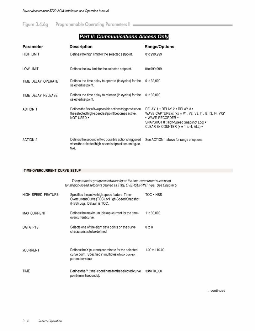
Power Measurement 3720 ACM Installation and Operation Manual
3-14 General Operation
Figure 3.4.6g Programmable Operating Parameters II
HIGH LIMIT 0 to 999,999
0 to 999,999LOW LIMIT
Defines the time delay to operate (in cycles) for theselected setpoint.
0 to 32,000TIME DELAY OPERATE
Defines the time delay to release (in cycles) for theselected setpoint.
0 to 32,000TIME DELAY RELEASE
Defines the first of two possible actions triggered whenthe selected high-speed setpoint becomes active.NOT USED •
RELAY 1 • RELAY 2 • RELAY 3 •WAVE CAPTURExx (xx = V1, V2, V3, I1, I2, I3, I4, VX)*• WAVE RECORDER •SNAPSHOT 8 (High-Speed Snapshot Log) •CLEAR Sx COUNTER (x = 1 to 4, ALL) •
ACTION 1
Defines the low limit for the selected setpoint.
Defines the high limit for the selected setpoint.
... continued
Part II: Communications Access Only
Parameter Description Range/Options
This parameter group is used to configure the time-overcurrent curve usedfor all high-speed setpoints defined as TIME OVERCURRNT type. See Chapter 5.
HIGH SPEED FEATURE Specifies the active high speed feature: Time-Overcurrent Curve (TOC), or High-Speed Snapshot(HSS) Log. Default is TOC.
TOC • HSS
Defines the maximum (pickup) current for the time-overcurrent curve.
1 to 30,000MAX CURRENT
Selects one of the eight data points on the curvecharacteristic to be defined.
0 to 8
Defines the X (current) coordinate for the selectedcurve point. Specified in multiples of MAX CURRENT
parameter value.
1.00 to 110.00xCURRENT
DATA PTS
TIME Defines the Y (time) coordinate for the selected curvepoint (in milliseconds).
33 to 10,000
TIME-OVERCURRENT CURVE SETUP
Defines the second of two possible actions triggeredwhen the selected high-speed setpoint becoming ac-tive.
ACTION 2 See ACTION 1 above for range of options.

Power Measurement 3720 ACM Installation and Operation Manual
General Operation 3-15
Figure 3.4.6h Programmable Operating Parameters II
Part II: Communications Access Only
Parameter Description Range/Options
RELAY CONTROL Selects one of the three relays to be programmed.
MODE Defines the type of operation the selected relay is toperform. See Section 3.7
RELAY SETUP
... continued
RESOLUTION Fixes the decimal resolution for the selectedcounter. Default is 0.
SCALE FACTOR Specifies the value represented by one pulse on theselected counter input (in units/pulse). Default is 1.
STATUS INPUT COUNTER SETUP
STATUS COUNTER Selects the status input counter to be programmed.
LOG STATUS CHANGES? Selects whether status input events will be logged.Default is YES. User must select for eachindividual status input.
YES • NO
EVENT LOG SETUP
1 to 3
SETPOINT •kWH IMP (pulsing) • kWH EXP • kWH TOT •kVARH IMP • kVARH EXP • kVARH TOT • kVAH
0 to 3
0.001 to 1000
1 to 4
ROLLOVER Specifies the maximum range before the selectedcounter rolls over to 0 (zero). Default is999,999,999.
0 to 999,999,999
PRESET Presets the counter reading to a specific value.Note: Counter will rollover to 0, not preset value.
0 to 999,999,999
VALUE For Rx MODE = SETPOINT: Specifies latch mode orsets pulse mode duration (in seconds). For Rx MODE= kWH, kVARH, or kVAH pulsing, disables pulsing ordefines number of unit-hours between pulses.0 = latch mode or disable pulsing
1 to 65535 = pulse duration or unit-hours
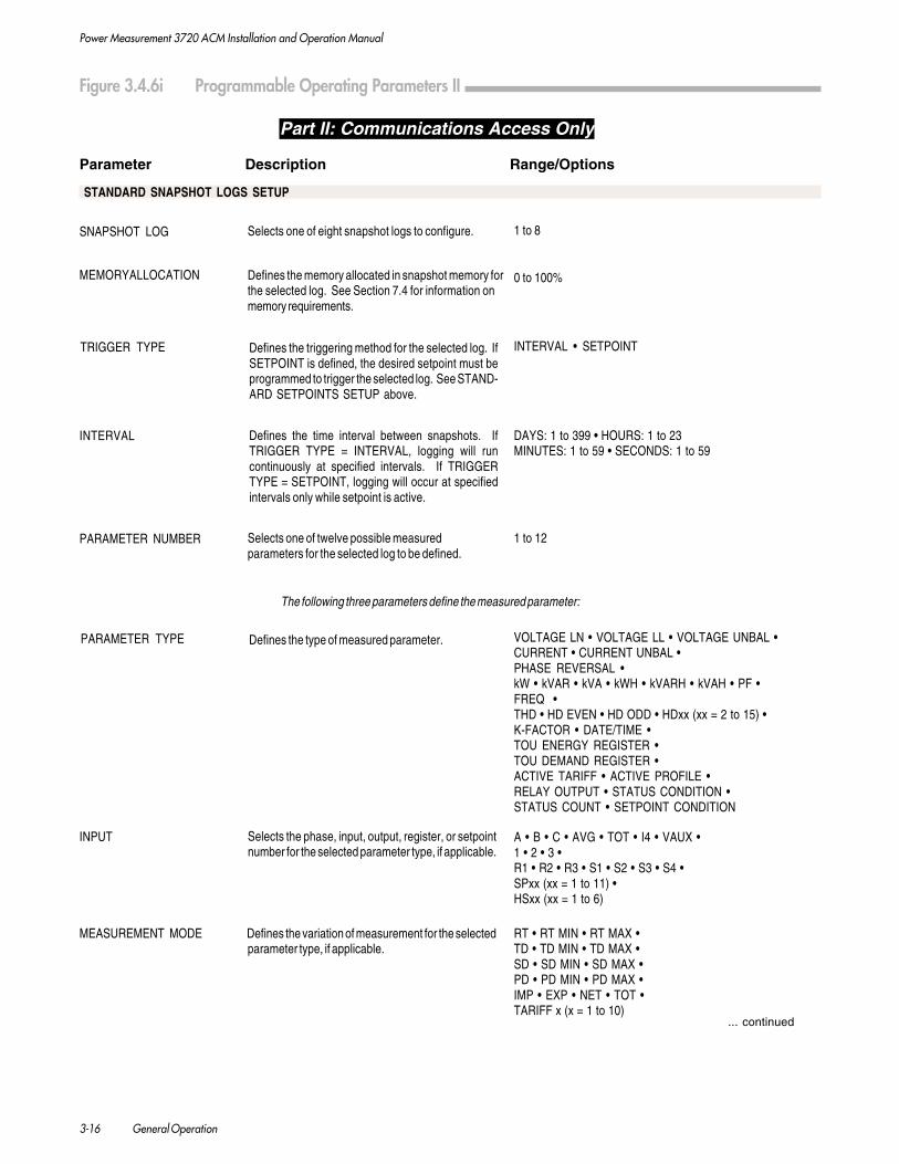
Power Measurement 3720 ACM Installation and Operation Manual
3-16 General Operation
Figure 3.4.6i Programmable Operating Parameters II
Part II: Communications Access Only
Parameter Description Range/Options
... continued
PARAMETER NUMBER
The following three parameters define the measured parameter:
Defines the type of measured parameter.PARAMETER TYPE
STANDARD SNAPSHOT LOGS SETUP
SNAPSHOT LOG
MEMORYALLOCATION
TRIGGER TYPE
INTERVAL
Selects one of twelve possible measuredparameters for the selected log to be defined.
Defines the time interval between snapshots. IfTRIGGER TYPE = INTERVAL, logging will runcontinuously at specified intervals. If TRIGGERTYPE = SETPOINT, logging will occur at specifiedintervals only while setpoint is active.
Defines the triggering method for the selected log. IfSETPOINT is defined, the desired setpoint must beprogrammed to trigger the selected log. See STAND-ARD SETPOINTS SETUP above.
Defines the memory allocated in snapshot memory forthe selected log. See Section 7.4 for information onmemory requirements.
Selects one of eight snapshot logs to configure. 1 to 8
0 to 100%
INTERVAL • SETPOINT
DAYS: 1 to 399 • HOURS: 1 to 23MINUTES: 1 to 59 • SECONDS: 1 to 59
1 to 12
VOLTAGE LN • VOLTAGE LL • VOLTAGE UNBAL •CURRENT • CURRENT UNBAL •PHASE REVERSAL •kW • kVAR • kVA • kWH • kVARH • kVAH • PF •FREQ •THD • HD EVEN • HD ODD • HDxx (xx = 2 to 15) •K-FACTOR • DATE/TIME •TOU ENERGY REGISTER •TOU DEMAND REGISTER •ACTIVE TARIFF • ACTIVE PROFILE •RELAY OUTPUT • STATUS CONDITION •STATUS COUNT • SETPOINT CONDITION
Selects the phase, input, output, register, or setpointnumber for the selected parameter type, if applicable.
INPUT A • B • C • AVG • TOT • I4 • VAUX •1 • 2 • 3 •R1 • R2 • R3 • S1 • S2 • S3 • S4 •SPxx (xx = 1 to 11) •HSxx (xx = 1 to 6)
MEASUREMENT MODE Defines the variation of measurement for the selectedparameter type, if applicable.
RT • RT MIN • RT MAX •TD • TD MIN • TD MAX •SD • SD MIN • SD MAX •PD • PD MIN • PD MAX •IMP • EXP • NET • TOT •TARIFF x (x = 1 to 10)

Power Measurement 3720 ACM Installation and Operation Manual
General Operation 3-17
Figure 3.4.6j Programmable Operating Parameters II
Part II: Communications Access Only
Parameter Description Range/Options
HIGH-SPEED SNAPSHOT LOG SETUP
HIGH SPEED FEATURE parameter must be set to HSS to enable the High-Speed Snapshot Log and disable Time-Overcurrent .See HIGH SPEED FEATURE under Time-Overcurrent Setup. Note: High-Speed Log is always Snapshot Log #8.
MEMORY ALLOCATION Defines the memory allocated in snapshot memoryfor the high-speed log. See Section 7.4 forinformation on memory requirements.
0 to 100%
TRIGGER TYPE Defines the triggering method. MANUAL requires atrigger command received via the comm. port. IfSETPOINT is defined, the setpoint must be pro-grammed to trigger the high-speed log. See SET-POINTS SETUP above. Note: Only 1 setpoint triggeris possible prior to rearming the high-speed log.
MANUAL • SETPOINT
INTERVAL Defines the time interval between snapshots in incre-ments of 2 cycles. Logging will run continuously atspecified intervals until stop condition is reached. SeeSection 8.4.2 for configuring a 1-shot mode.
0 to 130,000
PARAMETER NUMBER Selects one of twelve possible measured parametersfor the high-speed log to be defined.
1 to 12
STOP CONDITION LOG FULL = stop when allocated memory is used up.TIMED OUT = stop when DURATION has passed.SETPT OFF = stop when setpoint returns to inactive.
DURATION If STOP CONDITION = TIMED OUT, specifiesnumber of cycles until logging is stopped, inincrements of 2 cycles.
0 to 130,000
The following two parameters define the measured parameter:
PARAMETER TYPE Defines the type of measured parameter. VOLTAGE HS (LN or LL dependent on voltage mode) •VOLTAGE UNBAL HS • CURRENT HS •PHASE REVERSAL HS • kW • kVA • FREQUENCY •STATUS CONDITION • STATUS COUNT
Defines the condition following a trigger that willstop the high-speed logging function.
... continued
INPUT Selects the phase or input for the selected parametertype, if applicable.
A • B • C • AVG • TOT • I4 •S1 • S2 • S3 • S4
DAYLIGHT SAVINGS TIME SETUP
TIME OF CHANGE Specifies the beginning or the end of a daylightsavings time period. See Section 3.11 for moredetails.
Date given in the format YY/MM/DD/ HH:MM:SSMM should be in increments of 15 (00, 15, 30, 45)
CHANGE TO Indicates what the new time should be when youswitch to or from daylight savings time. Normallythis would be 1 hour different from TIME OF CHANGE.See Section 3.11 for more details.
Date given in the format YY/MM/DD/ HH:MM:SSMM should be in increments of 15 (00, 15, 30, 45)SS should be 00

Power Measurement 3720 ACM Installation and Operation Manual
3-18 General Operation
Figure 3.4.6k Programmable Operating Parameters II
Part II: Communications Access Only
Parameter Description Range/Options
GROUP BUTTON
PARAMETER NUMBER
PARAMETER TYPE Defines the type of measured parameter. VOLTAGE LN • VOLTAGE LL • VOLTAGE UNBAL •CURRENT • CURRENT UNBAL •kW • kVAR • kVA • kWH • kVARH • kVAH • PF • FREQ •THD • HD EVEN • HD ODD • HDxx (xx = 2 to 15) •K-FACTOR • DATE/TIME •TOU ENERGY REGISTER •TOU DEMAND REGISTER •ACTIVE TARIFF • ACTIVE PROFILE •RELAY OUTPUT • STATUS CONDITION •STATUS COUNT • SETPOINT CONDITION
PHASE BUTTON Defines the sequence of phases, inputs, setpointnumbers, or harmonic numbers accessible using thePHASE button. List of available options is dependent onthe PARAMETER TYPE defined above.
Any phase sequence • Any 3-phase display • Any relay orstatus input sequence • Any setpoint sequence • Anycombination of other measured or status parameters
MODE FUNCTION Defines the sequence of measurement variationsaccessible using the MODE function, if applicable.Options listing only a single mode will effectivelydisable the MODE function, since no additionalmodes will be available to the user.
Any combination of modes, includingRT • TD • SD • MIN • MAX • IMP • EXP • NET • TOT
Selects one of sixteen min/max logs to configure. 1 to 16
PARAMETER NUMBER
The following three parameters define the measured parameter:
PARAMETER TYPE Defines the type of measured parameter.
INPUT A • B • C • AVERAGE • TOT • I4 • VAUX
MEASUREMENT MODE
... continued
Selects the phase or input for the selectedparameter type, if applicable.
Selects which GROUP button to configure. 1 • 2
Selects the measured parameter to be defined. 1 to 18
The following three parameters define the measured parameter:
VOLTAGE LN • VOLTAGE LL • VOLTAGE UNBAL •CURRENT • CURRENT UNBAL • PHASE REVERSAL* •kW • kVAR • kVA • kWH* • kVARH* • kVAH* • PF • FREQ •THD • HD EVEN • HD ODD • HDxx (xx = 2 to 15) •K-FACTOR • DATE/TIME* •TOU ENERGY REGISTER* • TOU DEMAND REGISTER* •ACTIVE TARIFF* • ACTIVE PROFILE* •RELAY OUTPUT* • STATUS CONDITION* •STATUS COUNT* • SETPOINT CONDITION*
* Note: Parameter types and modes marked by anasterisk cannot be used as the min/max trigger, butcan be defined as coincident parameters.
Defines the variation of measurement for theselected parameter type, if applicable.
GROUP BUTTONS SETUP
PROGRAMMABLE MINIMUM/MAXIMUM LOGS SETUP
MIN/MAX LOG
Selects the min/max trigger or one of the 15 possiblecoincident parameters for the selected log to be defined.Parameter 1 is the trigger parameter.
1 to 16
RT • TD • SD •MIN* • MAX* • IMP* • EXP* • NET* • TOT*

Power Measurement 3720 ACM Installation and Operation Manual
General Operation 3-19
Figure 3.4.6 l Programmable Operating Parameters II
Part II: Communications Access Only
Parameter Description Range/Options
STATUS INPUT AND RELAY LABELS SETUP
Defines the label for the inactive state of statusinput x (where x = 1 to 4).
STATUS x INACTIVE 20 character label
Defines the label for the active state of status inputx (where x = 1 to 4).
20 character labelSTATUS x ACTIVE
RELAY x INACTIVE Defines the label for the inactive (released) state ofrelay x (where x = 1 to 3).
20 character label
RELAY x ACTIVE Defines the label for the active (operated) state ofrelay x (where x = 1 to 3).
20 character label
TIME-OF-USE SETUP
Note: TOU parameters are programmable using Power Measurement’s PowerView for Windows software.
Configuring the Current Year or Next Year Profiles Tab
MONTH (scroll bar)
Configuring the Registers Tab
Selects the demand registers to define. Eachregister is available to all 10 tariffs.
kW Total SD • kW Total TD • kVA Total SD • kVA Total TD •kVAR Total SD • kVAR Total TD • Amp Avg SD • Amp Avg TD
1 to 16
Selects the day(s) of the month in which to apply aprofile.
1 to 31; SUN • MON • TUE • WED • THU • FRI • SAT
Selects one of the 16 daily profiles.
ENERGY REGISTERS
Click the arrow buttons to display the previous ornext month.
PROFILE
JAN • FEB • MAR • APR • MAY • JUN •JUL • AUG • SEP • OCT • NOV • DEC
DAY
DEMAND REGISTERS
Selects the energy registers to define. Eachregister is available to all 10 tariffs.
kW Total SD • kW Total TD • kVA Total SD • kVA Total TD •kVAR Total SD • kVAR Total TD • Amp Avg SD • Amp Avg TD
RESET (check boxes) Selects whether or not the demand/energy registerswill be reset.
Configuring the Rates/Tariffs Tab
PROFILE Selects one of 16 daily profiles to program. Profile 1 to 16
SCHEDULE Selects the time interval for which to apply a tariff. 12:00 AM to 11:45 PM, in 15-minute increments
APPLY TARIFF Selects which of the ten available tariffs will beapplied to the selected time interval. A profile canhave a maximum of 8 tariff changes.
Tariff 1 to 10
PENALTY TARIFF Selects which one of the ten tariffs will be definedas the penalty tariff.
Tariff 1 to 10, None
checked, unchecked

Power Measurement 3720 ACM Installation and Operation Manual
3-20 General Operation
3.5 SETTING THE VOLTS SCALE, AMPSSCALE, I4 SCALE, VOLTS MODE,AND STANDARD FREQUENCY
This section details the minimum basic programming setuprequired for proper operation of the 3720 ACM.
Volts ScaleThe setting of the VOLTS SCALE parameter depends on thevoltage of the system being monitored and whether the 3720ACM is connected directly to the lines, or if PTs are used.
WARNING
PTs are required for connection to all Deltasystems.
Direct ConnectionThe various phase voltage input options of the 3720 ACMsupport direct connection to Wye systems up to 347 VACline-to-neutral / 600 VAC line-to-line and Single Phasesystems up to 347 VAC line-to-neutral / 694 VAC line-to-linewithout the need for PTs.
For direct connection, the VOLTS SCALE parameter of the 3720ACM must be set to the full scale rating of its phase voltageinputs. The basic model provides 120 VAC voltage inputs,which allow for direct connection to Wye systems up to 120VAC line-to-neutral / 208 VAC line-to-line and Single Phasesystems up to 120 VAC line-to-neutral / 240 VAC line-to-line.For the basic model, VOLTS SCALE must be set to 120.
Similarly, a 3720 ACM equipped with the 277 option must beset for a VOLTS SCALE of 277, while units with the 347 optionmust be set to a VOLTS SCALE of 347.
For system voltages between the ratings of the input optionsprovided by the 3720 ACM, the next highest input optionshould be used. For example, to monitor a 220 VAC line-to-neutral / 381 VAC line-to-line Wye system, a 3720 ACMequipped with the 277 option should be used. In this case,the VOLTS SCALE must still be set to 277.
PT ConnectionPTs must be used for Wye systems above 347 VAC line-to-neutral / 600 VAC line-to-line, Single Phase systems above347 VAC line-to-neutral / 694 VAC line-to-line, and for allDelta systems.
When using PTs, the VOLTS SCALE set for the 3720 ACM isdependent on the primary and secondary ratings of the PTsused.
For PTs that provide secondaries up to 120 VAC, use a basicmodel 3720 ACM (120 VAC inputs). If the PTs have second-aries rated at 120 VAC, set the VOLTS SCALE to the primaryrating of the PT. For example, for a 13.8 kV system, 120:1ratio PTs with primary ratings of 14.4 kV are typically used.For these PTs, set the VOLTS SCALE to 14400.
If the secondaries of the PTs are not rated at 120 VAC (i.e. 100,110, etc.), use the following formula to determine the requiredVOLTS SCALE :
For PTs that provide secondaries with ratings between 120 and277 VAC (i.e. 220), use a 3720 ACM equipped with the 277option. Use the following formula to determine the requiredVOLTS SCALE :
Amps Scale (phases A, B, and C)The basic model 3720 ACM provides 5 Amp phase currentinputs. If the CTs used are rated for a 5 Amp full scaleoutput, set the AMPS SCALE to the Primary Rating of the A, B,and C phase CTs being used.
NOTE
For the above parameter settings,
VOLTS SCALE x AMPS SCALE
should be less than 999,999,999 for correctdisplay of kW, kVAR, and kVA readingswhich have a maximum range of 999.999K.
I4 ScaleThe 3720 ACM has a fourth current input, designated I4.This input uses connections I41 and I42 on the terminal strip.Typically, this input is used to measure current in the neutralconductor. In installations with non-linear loads, oddharmonics can fail to cancel, producing significant currents inthe neutral conductor.
The ratings of this input are identical to the three phasecurrent inputs (5 Amps).
The I4 SCALE parameter of the 3720 ACM specifies the scaling forthe I4 input. This scaling is independent of the phase A, B,and C current inputs. This allows for a different primaryrating for the CT used for the I4 input. The I4 SCALE shouldbe set to the primary rating of the CT being used for the I4current input. This only applies if the CT used is rated for a5 Amp full scale output. If the CT is not rated for a 5 Ampfull scale output, contact the POWER MEASUREMENT factory.
Power Measurement 3720 ACM Installation and Operation Manual
General Operation 3-21
The I4 reading may be displayed from the front panel usingthe FUNCTION button.
Volts ModeThe VOLTS MODE should be set according to the systemconnection configuration (4W-WYE, 3W-WYE, DELTA, SINGLE).Refer to Section 2.5 and Figures 2.5.7a to 2.5.9 for moreinformation.
The 3720 ACM also offers a demonstration mode whichgenerates dynamic readings for all real-time measure-ments based on the input scales you program. Thesereadings can be viewed from the front panel or viacommunications. To use this feature, set VOLTS MODE toDEMO.
Standard FrequencyThe STANDARD FREQ parameter should be set according tothe frequency of the power signal the 3720 ACM is to bemonitoring. Options include 50 or 60 Hz.
It is important that this parameter is set correctly, as theaccuracy of the kW, kVAR, and power factor measure-ments can be seriously affected.
3.6 DISPLAY FORMAT
The 3720 ACM front panel display can present numericinformation and phase labels in a number of differentformats which reflect various world and industrialstandards. Two programmable parameters are used todefine the display format:
FORMATThis parameter allows you to select formats for numericinformation. The front panel display can present mea-sured values using either of the two following numericformats:
• 1,234.5This is the default. A comma is used for thethousands delimiter (radix), and a decimal point isused for the decimal delimiter.
• 1234,5No thousands delimiter is used, and a comma isused for the decimal delimiter.
PHASE LABELSThis parameter defines the three letters used for the phaselabels. The possible choices are ABC (default), XYZ, RYB andRST.
3.7 CONTROL RELAY OPERATION
The 3720 ACM provides three control relays (R1 to R3). Eachrelay can switch AC loads of up to 277 Volts at 10 Amps andDC loads of up to 30 Volts at 10 Amps. Chapter 2 provideswiring requirements for the relays.
The operation of each relay may be controlled in a number ofdifferent ways for various applications:
• Setpoint control on selected measured parameters,controlled by user-definable conditions. This is usefulfor applications such as activation of alarms or trippingof breakers for demand, power factor, or load control.Setpoint operation is described in detail in Chapter 6.
• kWH, kVARH, or kVAH pulse output.
• Manual forced control by the user through remotecommands made via the communications port. Thismust be performed via using an IBM PC running POWER
MEASUREMENT’s SCADA software, or a compatible third-party system.
A group of programmable operating parameters has beenprovided which assign relay operation. These are accessible viacommunications only. The parameters allow each of the threerelays to be assigned to setpoints (in latch or pulse mode), kWHpulsing, kVARH pulsing, or kVAH pulsing. POWER
MEASUREMENT’s SCADA system provides configuration screensfor redefining the relay parameters.
Setpoint Relay OperationFor setpoint operation, the relays can provide latched or pulsedoperation. In latch mode, the relay is operated (i.e. normallyopen contacts are closed) for the duration that the assignedsetpoint is active. In pulsed mode, when the setpoint becomesactive the relay operates for a specified pulse duration.
Set MODE to SETPOINT for setpoint operation. Set VALUE to zero(VALUE = 0).
CAUTION
While you are programming the 3720 ACMvia communications, no setpoint-controlledrelay operation occur until after you com-plete the programming sequence. The 3720ACM then assesses the status of eachsetpoint and performs any required opera-tions.

Power Measurement 3720 ACM Installation and Operation Manual
3-22 General Operation
kWh, kVARh OR kVAh Pulse OperationEach relay can be configured for energy pulsing. Pulses can bebased on kWh Imported, kWh Exported, kWh Total, kVARhImported, kVARh Exported, kVARh Total, or kVAh. The MODE
parameter is used to set the type of pulsing. The VALUE param-eter is used to set the number of unit-hours between pulses.
NOTE
1. A relay configured for energy pulsingwill not respond to an assignedsetpoint that becomes active.
2. Maximum pulse rate for the relays is 1pulse every 2 seconds (0.5 Hz).
Manual Forced Relay OperationsOnly a setpoint relay (Rx MODE = SETPOINT) may be forcedoperated or released using commands made via communica-tions. Manual commands override current setpoint condition.
If the relay is operating in pulse mode (Rx VALUE > 0), a forcedoperate command initiates a pulse of length equivalent to thevalue set by the Rx VALUE parameter for that relay. Thisoperation is logged in the event log and indicates that therelay was pulsed. A forced release command has no effect.
If the relay is operating in latch mode (Rx VALUE = 0), itbehaves normally for forced operate, forced release, and returnto normal (return to setpoint control) commands.
See below for manual relay control special cases.
Relay Event LoggingFor a relay assigned to setpoint operation (MODE = SETPOINT),the Event Log logs relay operations in one of two ways,depending on whether the relay has been set to operate inlatch or pulse mode:
• Latch mode (VALUE = 0): The event log records thatthe relay was operated (ON) when the setpoint becomesactive and released (OFF) when the setpoint returns toan inactive state.
• Pulse mode (VALUE > 0): The event log shows that therelay is pulsed when the setpoint becomes active.When the setpoint returns to its inactive state, thesetpoint event is logged, but does not indicate therelay, since no pulse is generated.
If the relay is assigned to kWH, kVAH or kVAH PULSE mode,no relay operations are logged.
Manual forced relay commands are logged in the Event Log;however special cases exist which are described below.
Manual Relay Command Special CasesIf a manual forced operate command for a selected relay isreceived while that relay is currently in a forced operatedstate, the relay command is ignored, and is not logged. Thisalso holds true for a forced release command to a relay alreadyin a forced released state. Manual relay commands made torelays which are in a kWH, kVAH or kVAH PULSE mode willalso not be logged.
3.8 STATUS INPUT OPERATION
The 3720 ACM provides four digital status inputs (S1 to S4)which can each be used to sense the condition of an externaldry (volts free) contact. Chapter 2 provides wiring diagramsillustrating various requirements and connection methods forthe status inputs.
A minimum pulse width of 40 milliseconds is required forreliable sensing of status input changes. The status inputsmay only be used for external contact sensing. In thisapplication, a contact closure is sensed as ACTIVE, and acontact opening is sensed as INACTIVE.
Pulse CountingThe 3720 ACM maintains a counter for each of the fourstatus inputs. The maximum frequency the counter accuratelyfollows is 10 Hz. A number of programmable parameters,accessible via communications, are provided to allow eachcounter to be customized for specific applications.
RESOLUTIONThe decimal resolution for each counter can be fixedbetween 0 and 3. For example, a setting of 3 woulddisplay a total pulse count of 1234 as 1.234.
SCALE FACTORThis parameter allows the total pulse count to be scaledby a factor of 0.001 to 1000 units per pulse. For example,a setting of 200 would display a total pulse count of 10as 2,000.
ROLLOVERThe maximum (scaled) reading that each counter canachieve prior to rollover to 0 (zero) can be defined. Thedefault is 999,999,999. This is the maximum range of thecounters.
PRESETYou can preset each counter reading to a specific value.This is a 1-shot function only. If the counter rollovervalue is reached, it rolls over to zero, not to the presetvalue. If the counter is zeroed, as described below, itsreading returns to the preset value once again.

Power Measurement 3720 ACM Installation and Operation Manual
General Operation 3-23
Resetting the Status Input CountersStatus input counter values can be manually reset to zero(0) using the CLEAR STATUS COUNT parameter from thefront panel in programming mode or via communications.Each counter can be cleared individually, or all counterscan be cleared together.
Counters can also be automatically reset using setpoints(see Chapter 6).
Demand SyncStatus Input S4 can be used to provide external demandinterval synchronization for demand measurements.Refer to Chapter 4, Section 4.3.1 for more information.
TOU Penalty Tariff ActivationStatus Input S3 can be used to activate the penalty tariffused by the 3720 ACM Time-Of-Use register system. Ifyou have defined a penalty tariff, the tariff remains ineffect for the entire duration that an active level (i.e.contact closure) is present on Status Input S3. Refer toChapter 5 for more information on Time-Of-Use.
NOTE
If the TOU penalty tariff is in use, Sta-tus Input S3 is disabled for all other con-tact sensing, pulse counting, or de-mand sync operations.
Viewing Status Input ConditionsThe condition of the status inputs and status inputcounter totals can be viewed from the front panel usingthe GROUP buttons (see Section 3.3.2) or via communica-tions. Chapter 4 lists all available status parameters.
Logging Status Input ConditionsStatus input changes can also be logged in the Event Logof the 3720 ACM which is accessible via the communica-tions port. Logging of status input changes can beenabled or disabled via communications.
Status Input SetpointsStatus input conditions can also be used for setpoints.This allows relay control functions to be performed basedon status input conditions. Refer to Chapter 6 for moreinformation.
3.9 AUXILIARY VOLTAGE INPUTOPERATION
The 3720 ACM has an auxiliary voltage input (VAUX) whichallows an external voltage (1 VAC nominal, 1.25 VAC max.)to be measured and displayed with user-programmablescaling.
Two parameters must be set:
• VAUX SCALE
This parameter defines what reading is displayed witha 1.000 VACRMS input applied (i.e. full scale input).Range is 0 to 999,999.
• VAUX ZERO
This parameter defines what reading is displayed witha 0.000 VACRMS input applied. Range is -999,999 to999,999.
EXAMPLEA transducer is used to measure the operating temperature ofa transformer’s windings. The output of the transducer isconnected to the VAUX input of the 3720 ACM. A transduceroutput of 1.000 VAC represents 100.0 oC. A transduceroutput of 0.000 VAC represents 30.0 oC.
Set VAUX SCALE to 100. Set VAUX ZERO to 30.
In this example, a transducer output of 1.000 VAC producesa reading of 100, while an output of 0.000 VAC produces areading of 30.

Power Measurement 3720 ACM Installation and Operation Manual
3-24 General Operation
NOTE
The 3720 ACM does not display VAUX read-ings with decimal places of resolution; how-ever, additional integer digits of resolutioncan be obtained by setting both scaling pa-rameters to larger values. For the ex-ample above, setting VAUX SCALE to 1000and VAUX ZERO to 300 provides one moredigit of resolution. In this case, rememberto interpret the least significant digit as onedecimal place (i.e. a reading of 850 isequivalent to 85.0).
3.10 AUXILIARY CURRENT OUTPUTOPERATION
The 3720 ACM is equipped with an analog current output(IOUT) that may be programmed to deliver a current propor-tional to a measured parameter. The maximum load on thecurrent output is 250 ohms resistive. Four parameters mustbe set:
• IOUT SCALE
This parameter defines the value of the associatedmeasured parameter corresponding to full scale currentoutput. If IOUT KEY = FREQUENCY, IOUT SCALE should beset to the desired parameter value x 100 for which thecurrent output is 20.0 mA. Range is 0 to 999,999.
• IOUT ZERO
This parameter defines the value of the associatedmeasured parameter corresponding to zero scalecurrent output (i.e. the zero offset). For an IOUT RANGE
value of 0-20 mA, IOUT ZERO should be set to thedesired parameter value for which the current outputis 0.0 mA. For an IOUT RANGE value of 4-20 mA, IOUT
ZERO should be set to the parameter value for whichthe current output is 4.0 mA. IOUT ZERO can bepositive or negative. Range is-999,999 to 999,999
• IOUT KEY
This defines the measured parameter to which thecurrent output is proportional. Figure 3.4.6b providesa list of measured parameters that may be used.
• IOUT RANGE
This defines the maximum current output range.Choices are 0-20 mA or 4-20 mA.
EXAMPLEThe IOUT current output must be proportional to the Phase Acurrent reading. The maximum Phase A current expected isapproximately 2000 Amps. The minimum Phase A currentexpected is approximately 500 Amps. The IOUT output isbeing used to provide input to a chart recorder with an inputrange of 4 to 20 mA.
Set IOUT KEY to CURRENT A. Set IOUT RANGE to 4 TO 20 mA to matchthe full input range of the chart recorder. To produce themaximum chart recorder range of deflection, set IOUT SCALE to2000 and IOUT ZERO to 500.
In this example, a Phase A current input reading of 500produces 4 mA at the IOUT output (minimum scale deflectionof the chart recorder). A Phase A current reading of 2000produces an output of 20 mA (maximum scale deflection ofthe chart recorder).
3.11 DAYLIGHT SAVINGS TIME
The 3720 ACM supports up to two years of automaticdaylight savings time changes (two changes per year). Thiseliminates the need to manually change the system clock fordaylight savings time and ensures that the time stampsaccompanying many of the 3720 ACM parameters appearcorrectly.
NOTE
Daylight savings time support is onlyavailable via communications.
You can access the daylight savings time setup parametersthrough POWER MEASUREMENT’s SCADA software. TheSCADA software provides access to two time changes, or oneyear’s worth. (The other two time changes are available forthird party SCADA systems that support four time changes.)
A time change is controlled by the following two variables:
• TIME OF CHANGE
This parameter specifies the date and a daylightsavings time period starts or ends. It should bespecified in the format
YY/MM/DD HH:MM:SS
where MM must be a 15-minnute increment(00, 15, 30 or 45) and SS should be 00.
• CHANGE TO
This parameter specifies the new date and time thedevice’s clock should change to when a TIME OF CHANGE
occurs. CHANGE TO should be specified using the sameformat as TIME OF CHANGE.
If the 3720 ACM gets disconnected from the SCADA soft-ware, it will still execute the time changes.
EXAMPLEIf Daylight Savings starts on April 4 at 2 am and ends onOctober 30 at 2 am, you need to put your clock one hourforward in the spring, and one hour back in the fall. You cando this using POWER MEASUREMENT’s SCADA software byspecifying:
Time of Change : 95/04/24 2:00:00Change to : 95/04/24 3:00:00Time of Change : 95/10/30 2:00:00Change to : 95/10/30 1:00:00

Power Measurement 3720 ACM Installation and Operation Manual
Measured Parameters & Status Information 4-1
4 MEASURED PARAMETERS ANDSTATUS INFORMATION
4.1 INTRODUCTION
This chapter provides detailed descriptions of each measuredparameter and all status information provided by the 3720ACM, except for Time-Of-Use registers. TOU is described indetail in Chapter 5.
Parameters are categorized as follows:
1. High-Speed Parameters
2. Real-Time
BASE MEASUREMENTS• Power Parameters
- voltage- current- real, reactive, and apparent power- frequency- power factor
• Harmonic Distortion
- total, even, odd, individual harmonics- K-Factor
MEASUREMENT MODES• Demand
• Minima & Maxima
3. Bi-Directional Energy
BASE MEASUREMENTS• Real, reactive, and apparent energy
MEASUREMENT MODES• Imported, exported, net, and total
4. Status Information• Control relay conditions,
status input conditions,status input counter totals,and setpoint conditions
• Self-diagnostic information
The following sections of this chapter provide complete listingof all measured parameters, their associated display labels,and detailed information on each parameter type.
A complete list of accuracies, display resolutions, and rangeof readings for all measurements can be found in AppendixD.
Measured Parameter Display LabelsThe large number of measured parameter types and theirassociated measurement mode combinations requires that the3720 ACM display parameter names on its front panel usingspecial formats.
The following sections of this chapter illustrate how variousparameter types are displayed. As mentioned in Chapter 3,parameter names which require a large number of characterswill be presented using the entire display.
Access to ParametersAll measurements, measurement modes (including user-defined sliding window demands), and status parameters arecontinuously monitored or calculated internally by the 3720ACM. As described in Chapter 3, you can access a largenumber of parameters directly from the front panel using thedefault PHASE, FUNCTION, and GROUP button displays, or byconfiguring the GROUP buttons to provide access to specificparameters of interest.
The complete selection of measured parameters and statusinformation is always accessible via remote communications(Chapter 9).
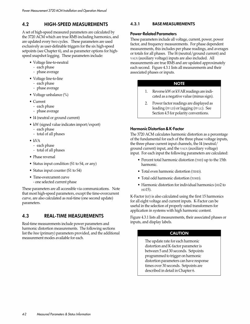
Power Measurement 3720 ACM Installation and Operation Manual
4-2 Measured Parameters & Status Information
4.2 HIGH-SPEED MEASUREMENTS
A set of high-speed measured parameters are calculated bythe 3720 ACM which are true RMS including harmonics, andare updated every two cycles. These parameters are usedexclusively as user-definable triggers for the six high-speedsetpoints (see Chapter 6), and as parameter options for high-speed snapshot logging. These parameters include:
• Voltage line-to-neutral- each phase- phase average
• Voltage line-to-line- each phase- phase average
• Voltage unbalance (%)
• Current- each phase- phase average
• I4 (neutral or ground current)
• kW (signed value indicates import/export)- each phase- total of all phases
• kVA- each phase- total of all phases
• Phase reversal
• Status input condition (S1 to S4, or any)
• Status input counter (S1 to S4)
• Time-overcurrent curve- one selected current phase
These parameters are all accessible via communications. Notethat most high-speed parameters, except the time-overcurrentcurve, are also calculated as real-time (one second update)parameters.
4.3 REAL-TIME MEASUREMENTS
Real-time measurements include power parameters andharmonic distortion measurements. The following sectionslist the base (primary) parameters provided, and the additionalmeasurement modes available for each.
4.3.1 BASE MEASUREMENTS
Power-Related ParametersThese parameters include all voltage, current, power, powerfactor, and frequency measurements. For phase dependentmeasurements, this includes per phase readings, and averagesor totals for all phases. The I4 (neutral/ground current) andVAUX (auxiliary voltage) inputs are also included. Allmeasurements are true RMS and are updated approximatelyeach second. Figure 4.3.1 lists all measurements and theirassociated phases or inputs.
NOTE
1. Reverse kW or kVAR readings are indi-cated as a negative value (minus sign).
2. Power factor readings are displayed asleading (PF LD) or lagging (PF LG). SeeSection 4.5 for polarity conventions.
Harmonic Distortion & K-FactorThe 3720 ACM calculates harmonic distortion as a percentageof the fundamental for each of the three phase voltage inputs,the three phase current input channels, the I4 (neutral/ground current) input, and the VAUX (auxiliary voltage)input. For each input the following parameters are calculated:
• Percent total harmonic distortion (THD) up to the 15thharmonic.
• Total even harmonic distortion (TEHD).
• Total odd harmonic distortion (TOHD).
• Harmonic distortion for individual harmonics (HD2 toHD15).
K-Factor (KF) is also calculated using the first 15 harmonicsfor all eight voltage and current inputs. K-Factor can beuseful in the selection of properly rated transformers forapplication in systems with high harmonic content.
Figure 4.3.1 lists all measurements, their associated phases orinputs, and display labels.
CAUTION
The update rate for each harmonicdistortion and K-factor parameter isbetween 5 and 30 seconds. Setpointsprogrammed to trigger on harmonicdistortion parameters can have responsetimes over 30 seconds. Setpoints aredescribed in detail in Chapter 6.

Power Measurement 3720 ACM Installation and Operation Manual
Measured Parameters & Status Information 4-3
Figure 4.3.1 List of Real-Time Base Measurements & Display Labels
Parameter Measurements & Display LabelsType Description Phase or Input1
A B C Average Total I4 Vaux
Voltage 2 Voltage line-to-neutral (VLN) A B C VXVoltage line-to-line (VLL) A, B, C, ,Voltage unbalance (%) V UNB
Current 2 Current A B C I4Current unbalance (%) A UNB
Power Real power KW A KW B KW C KW Reactive power KVR A KVR B KVR C KVR Apparent power KVA A KVA B KVA C KVA
Power Factor Power Factor PF A PF B PF C PF
Frequency Frequency (phase A) HZ
Harmonic Total harmonic distortion THD V1 THD V2 THD V3 THD I4 THD VXDistortion (2nd + 3rd + ... 15th) THD I1 THD I2 THD I3(in percent of Total even harmonic distortion TEHD V1 TEHD V2 TEHD V3 TEHD I4 TEHD VXfundamental) (2nd + 4th + ... 14th) TEHD I1 TEHD I2 TEHD I3
Total odd harmonic distortion TOHD V1 TOHD V2 TOHD V3 TOHD I4 TOHD VX(3rd + 5th + ... 15th) TOHD I1 TOHD I2 TOHD I3Individual harmonic distortion HDx V1 HDx V2 HDx V3 HDx I4 HDx VX(2nd or 3rd or ..15th) x = 2 to 15 HDx I1 HDx I2 HDx I3
K-Factor K-Factor KF V1 KF V2 KF V3 KF I4 KF VXKF I1 KF I2 KF I3
1 Phase labels are user-definable (see Section 3.6). A comma indicates a line-to-line voltage measurement. An asteriskrepresents average of all phases for voltage and current measurements, and total for all phases for power and power factormeasurements.
2 Voltage and current readings for individual phases and phase averages are presented on the Volts-Phase-Amps-Functiondisplay without additional parameter labels. Normal volt/amp measurements are PT/CT primary measurement.Measurements showing are measurements derived from the secondary of the PT/CT (i.e. 120.0 indicates 120.0 Volts atthe meter inputs).
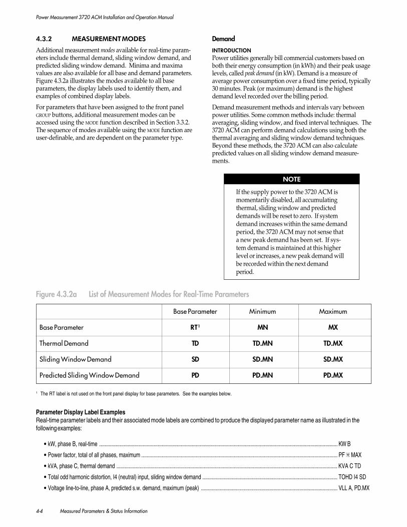
Power Measurement 3720 ACM Installation and Operation Manual
4-4 Measured Parameters & Status Information
4.3.2 MEASUREMENT MODES
Additional measurement modes available for real-time param-eters include thermal demand, sliding window demand, andpredicted sliding window demand. Minima and maximavalues are also available for all base and demand parameters.Figure 4.3.2a illustrates the modes available to all baseparameters, the display labels used to identify them, andexamples of combined display labels.
For parameters that have been assigned to the front panelGROUP buttons, additional measurement modes can beaccessed using the MODE function described in Section 3.3.2.The sequence of modes available using the MODE function areuser-definable, and are dependent on the parameter type.
Demand
INTRODUCTIONPower utilities generally bill commercial customers based onboth their energy consumption (in kWh) and their peak usagelevels, called peak demand (in kW). Demand is a measure ofaverage power consumption over a fixed time period, typically30 minutes. Peak (or maximum) demand is the highestdemand level recorded over the billing period.
Demand measurement methods and intervals vary betweenpower utilities. Some common methods include: thermalaveraging, sliding window, and fixed interval techniques. The3720 ACM can perform demand calculations using both thethermal averaging and sliding window demand techniques.Beyond these methods, the 3720 ACM can also calculatepredicted values on all sliding window demand measure-ments.
NOTE
If the supply power to the 3720 ACM ismomentarily disabled, all accumulatingthermal, sliding window and predicteddemands will be reset to zero. If systemdemand increases within the same demandperiod, the 3720 ACM may not sense thata new peak demand has been set. If sys-tem demand is maintained at this higherlevel or increases, a new peak demand willbe recorded within the next demandperiod.
Parameter Display Label ExamplesReal-time parameter labels and their associated mode labels are combined to produce the displayed parameter name as illustrated in thefollowing examples:
• kW, phase B, real-time ............................................................................................................................................................................... KW B
• Power factor, total of all phases, maximum ................................................................................................................................................ PF MAX
• kVA, phase C, thermal demand .................................................................................................................................................................. KVA C TD
• Total odd harmonic distortion, I4 (neutral) input, sliding window demand .................................................................................................... TOHD I4 SD
• Voltage line-to-line, phase A, predicted s.w. demand, maximum (peak) ..................................................................................................... VLL A, PD.MX
Figure 4.3.2a List of Measurement Modes for Real-Time Parameters
1 The RT label is not used on the front panel display for base parameters. See the examples below.
Base Parameter Minimum Maximum
Base Parameter RT1 MN MX
Thermal Demand TD TD.MN TD.MX
Sliding Window Demand SD SD.MN SD.MX
Predicted Sliding Window Demand PD PD.MN PD.MX

Power Measurement 3720 ACM Installation and Operation Manual
Measured Parameters & Status Information 4-5
THERMAL DEMANDThermal demand values are calculated automatically for allbase real-time parameters. The 3720 ACM uses a methodwhich is equivalent to thermal averaging. For thermalaveraging, the traditional demand indicator responds toheating of a thermal element in a Watt-Hour meter. Thethermal demand period is determined by the thermal timeconstant of the element, typically 15 to 30 minutes.
By default, the 3720 ACM uses base 10 logarithm to calculatethe demand curve; this is the characteristic curve used bymost utilities. The demand period is the period of time itwould take the demand to ramp up to approximately 90% ofthe steady-state value (see Figure 4.3.2b).
For thermal demand, the programmable demand period is setby the THERMAL PERIOD parameter. When you adjust thisparameter, the shape of the curve in Figure 4.3.2b changes;this allows you to match the power utility’s demand calcula-tion technique.
Another (less popular) method uses the natural logarithmcharacteristic to calculate the demand curve; the demandperiod for this curve is the period of time it would take thedemand to ramp up to approximately 63% of the steady-statevalue.
To configure the 3720 ACM to use natural logarithm, you willneed to set up the thermal demand characteristic using thePowerView for Windows software.
Each thermal demand measurement also has associatedminima/maxima parameters available.
NOTE
On the front panel display, thermaldemand parameters are indicated usingthe label TD.
SLIDING WINDOW DEMANDThe 3720 ACM can provide up to ten sliding windowdemand measurements. The type of measured parametersthat the sliding window values are calculated for are user-programmable via communications. The first four slidingwindow demand parameters have been programmed intothe 3720 ACM at the factory, but you can reprogram themif you wish. These are:
• Current, average of all phases
• kW, total of all phases
• kVAR, total of all phases
• kVA, total of all phases
To compute sliding window demand values, the 3720ACM uses the sliding window averaging (or rolling interval)technique which divides the demand interval into sub-periods. The demand is measured electronically based onthe average load level over the most recent set of sub-periods. This has the effect of improving the responsetime as compared to the fixed interval method.
PARAMETER&
PARAMETER DEMAND
TIME
100%
0%
LOAD
Figure 4.3.2b Thermal Demand Calculation
90%
DEMAND
DEMAND PERIOD
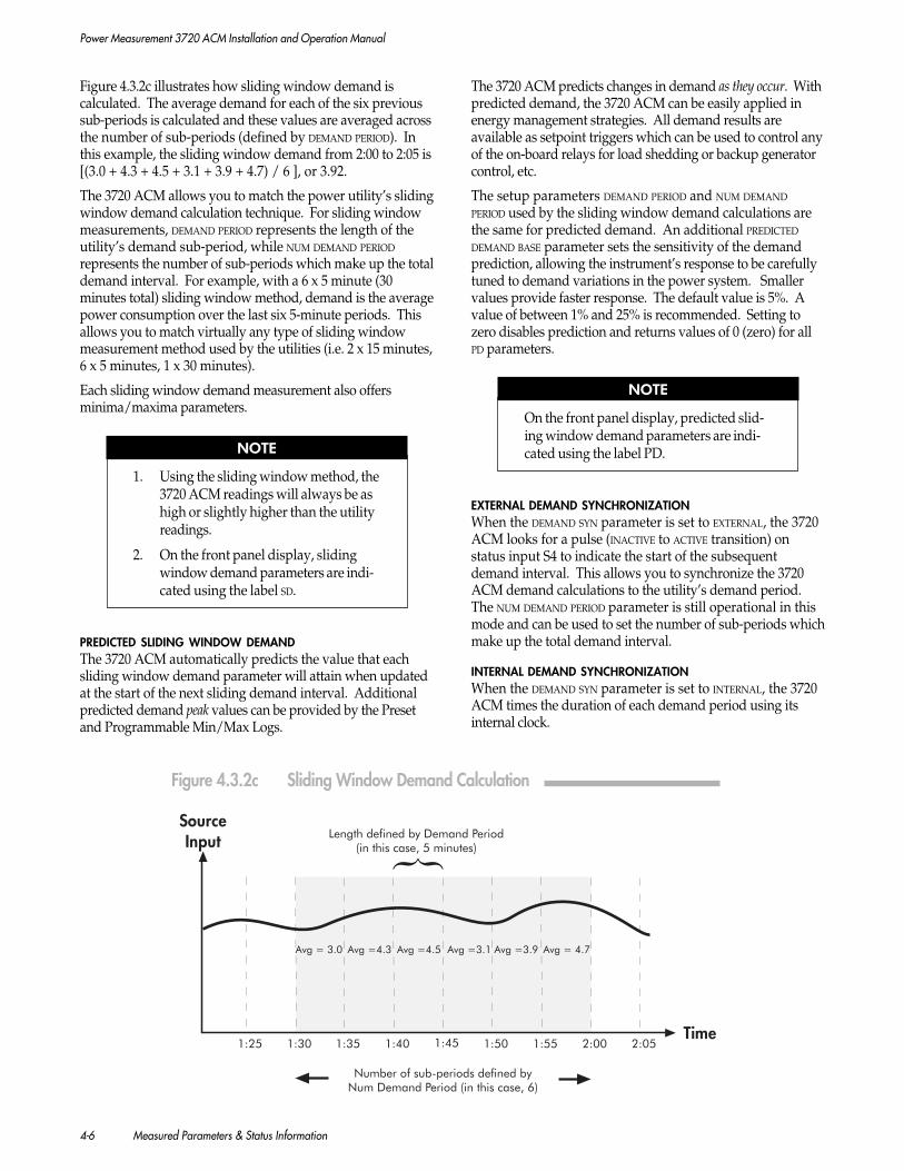
Power Measurement 3720 ACM Installation and Operation Manual
4-6 Measured Parameters & Status Information
Figure 4.3.2c illustrates how sliding window demand iscalculated. The average demand for each of the six previoussub-periods is calculated and these values are averaged acrossthe number of sub-periods (defined by DEMAND PERIOD). Inthis example, the sliding window demand from 2:00 to 2:05 is[(3.0 + 4.3 + 4.5 + 3.1 + 3.9 + 4.7) / 6 ], or 3.92.
The 3720 ACM allows you to match the power utility’s slidingwindow demand calculation technique. For sliding windowmeasurements, DEMAND PERIOD represents the length of theutility’s demand sub-period, while NUM DEMAND PERIOD
represents the number of sub-periods which make up the totaldemand interval. For example, with a 6 x 5 minute (30minutes total) sliding window method, demand is the averagepower consumption over the last six 5-minute periods. Thisallows you to match virtually any type of sliding windowmeasurement method used by the utilities (i.e. 2 x 15 minutes,6 x 5 minutes, 1 x 30 minutes).
Each sliding window demand measurement also offersminima/maxima parameters.
NOTE
1. Using the sliding window method, the3720 ACM readings will always be ashigh or slightly higher than the utilityreadings.
2. On the front panel display, slidingwindow demand parameters are indi-cated using the label SD.
PREDICTED SLIDING WINDOW DEMANDThe 3720 ACM automatically predicts the value that eachsliding window demand parameter will attain when updatedat the start of the next sliding demand interval. Additionalpredicted demand peak values can be provided by the Presetand Programmable Min/Max Logs.
The 3720 ACM predicts changes in demand as they occur. Withpredicted demand, the 3720 ACM can be easily applied inenergy management strategies. All demand results areavailable as setpoint triggers which can be used to control anyof the on-board relays for load shedding or backup generatorcontrol, etc.
The setup parameters DEMAND PERIOD and NUM DEMAND
PERIOD used by the sliding window demand calculations arethe same for predicted demand. An additional PREDICTED
DEMAND BASE parameter sets the sensitivity of the demandprediction, allowing the instrument’s response to be carefullytuned to demand variations in the power system. Smallervalues provide faster response. The default value is 5%. Avalue of between 1% and 25% is recommended. Setting tozero disables prediction and returns values of 0 (zero) for allPD parameters.
NOTE
On the front panel display, predicted slid-ing window demand parameters are indi-cated using the label PD.
EXTERNAL DEMAND SYNCHRONIZATIONWhen the DEMAND SYN parameter is set to EXTERNAL, the 3720ACM looks for a pulse (INACTIVE to ACTIVE transition) onstatus input S4 to indicate the start of the subsequentdemand interval. This allows you to synchronize the 3720ACM demand calculations to the utility’s demand period.The NUM DEMAND PERIOD parameter is still operational in thismode and can be used to set the number of sub-periods whichmake up the total demand interval.
INTERNAL DEMAND SYNCHRONIZATIONWhen the DEMAND SYN parameter is set to INTERNAL, the 3720ACM times the duration of each demand period using itsinternal clock.
Figure 4.3.2c Sliding Window Demand Calculation
SourceInput
Time
Length defined by Demand Period(in this case, 5 minutes)
Number of sub-periods defined byNum Demand Period (in this case, 6)
Avg = 3.0 Avg =4.5 Avg =3.9Avg =4.3 Avg =3.1 Avg = 4.7
2:001:551:501:451:401:351:301:25 2:05
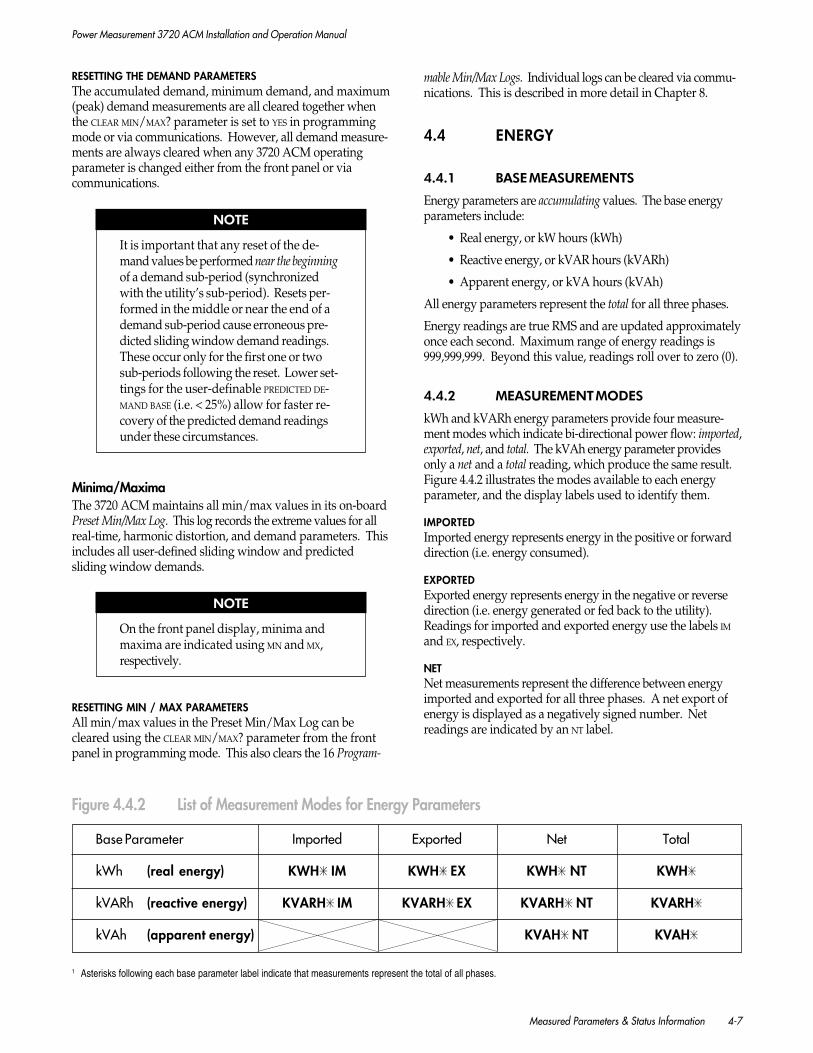
Power Measurement 3720 ACM Installation and Operation Manual
Measured Parameters & Status Information 4-7
RESETTING THE DEMAND PARAMETERSThe accumulated demand, minimum demand, and maximum(peak) demand measurements are all cleared together whenthe CLEAR MIN/MAX? parameter is set to YES in programmingmode or via communications. However, all demand measure-ments are always cleared when any 3720 ACM operatingparameter is changed either from the front panel or viacommunications.
NOTE
It is important that any reset of the de-mand values be performed near the beginningof a demand sub-period (synchronizedwith the utility’s sub-period). Resets per-formed in the middle or near the end of ademand sub-period cause erroneous pre-dicted sliding window demand readings.These occur only for the first one or twosub-periods following the reset. Lower set-tings for the user-definable PREDICTED DE-MAND BASE (i.e. < 25%) allow for faster re-covery of the predicted demand readingsunder these circumstances.
Minima/MaximaThe 3720 ACM maintains all min/max values in its on-boardPreset Min/Max Log. This log records the extreme values for allreal-time, harmonic distortion, and demand parameters. Thisincludes all user-defined sliding window and predictedsliding window demands.
NOTE
On the front panel display, minima andmaxima are indicated using MN and MX,respectively.
RESETTING MIN / MAX PARAMETERSAll min/max values in the Preset Min/Max Log can becleared using the CLEAR MIN/MAX? parameter from the frontpanel in programming mode. This also clears the 16 Program-
mable Min/Max Logs. Individual logs can be cleared via commu-nications. This is described in more detail in Chapter 8.
4.4 ENERGY
4.4.1 BASE MEASUREMENTS
Energy parameters are accumulating values. The base energyparameters include:
• Real energy, or kW hours (kWh)
• Reactive energy, or kVAR hours (kVARh)
• Apparent energy, or kVA hours (kVAh)
All energy parameters represent the total for all three phases.
Energy readings are true RMS and are updated approximatelyonce each second. Maximum range of energy readings is999,999,999. Beyond this value, readings roll over to zero (0).
4.4.2 MEASUREMENT MODES
kWh and kVARh energy parameters provide four measure-ment modes which indicate bi-directional power flow: imported,exported, net, and total. The kVAh energy parameter providesonly a net and a total reading, which produce the same result.Figure 4.4.2 illustrates the modes available to each energyparameter, and the display labels used to identify them.
IMPORTEDImported energy represents energy in the positive or forwarddirection (i.e. energy consumed).
EXPORTEDExported energy represents energy in the negative or reversedirection (i.e. energy generated or fed back to the utility).Readings for imported and exported energy use the labels IMand EX, respectively.
NETNet measurements represent the difference between energyimported and exported for all three phases. A net export ofenergy is displayed as a negatively signed number. Netreadings are indicated by an NT label.
1 Asterisks following each base parameter label indicate that measurements represent the total of all phases.
Figure 4.4.2 List of Measurement Modes for Energy Parameters
Base Parameter Imported Exported Net Total
kWh (real energy) KWH IM KWH EX KWH NT KWH
kVARh (reactive energy) KVARH IM KVARH EX KVARH NT KVARH
kVAh (apparent energy) KVAH NT KVAH
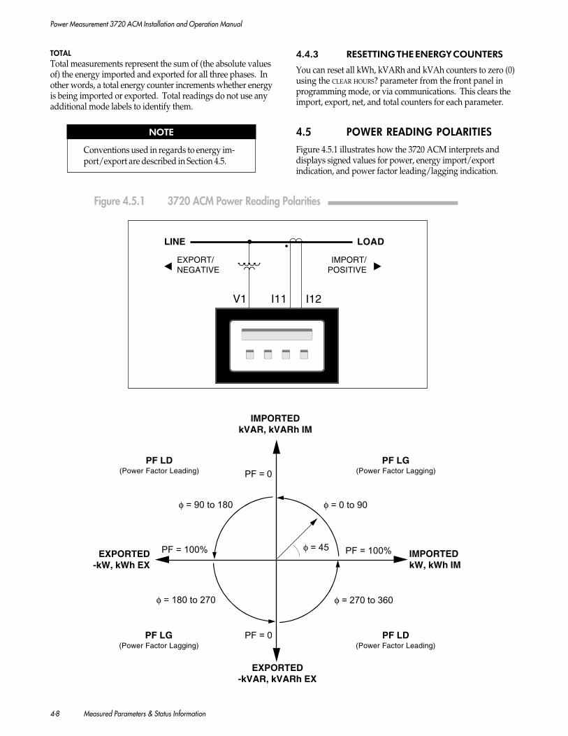
Power Measurement 3720 ACM Installation and Operation Manual
4-8 Measured Parameters & Status Information
TOTALTotal measurements represent the sum of (the absolute valuesof) the energy imported and exported for all three phases. Inother words, a total energy counter increments whether energyis being imported or exported. Total readings do not use anyadditional mode labels to identify them.
NOTE
Conventions used in regards to energy im-port/export are described in Section 4.5.
4.4.3 RESETTING THE ENERGY COUNTERS
You can reset all kWh, kVARh and kVAh counters to zero (0)using the CLEAR HOURS? parameter from the front panel inprogramming mode, or via communications. This clears theimport, export, net, and total counters for each parameter.
4.5 POWER READING POLARITIES
Figure 4.5.1 illustrates how the 3720 ACM interprets anddisplays signed values for power, energy import/exportindication, and power factor leading/lagging indication.
φ = 45
EXPORTED-kVAR, kVARh EX
φ = 0 to 90φ = 90 to 180
IMPORTEDkVAR, kVARh IM
PF LD(Power Factor Leading)
φ = 180 to 270 φ = 270 to 360
PF = 100% PF = 100% IMPORTEDkW, kWh IM
EXPORTED-kW, kWh EX
V1 I11 I12
LINE
IMPORT/POSITIVE
EXPORT/NEGATIVE
LOAD
PF LG(Power Factor Lagging)
PF LG(Power Factor Lagging)
PF LD(Power Factor Leading)
PF = 0
PF = 0
Figure 4.5.1 3720 ACM Power Reading Polarities

Power Measurement 3720 ACM Installation and Operation Manual
Measured Parameters & Status Information 4-9
NOTE
The polarity of energy import/exportreadings can be reversed by reversingthe polarity of the CTs connected to the3720 ACM.
4.6 STATUS INFORMATION
Status information includes the present conditions of thethree on-board relays, four digital (binary) status inputs,four status input counters, and seventeen user-program-mable setpoints.
Also included under this category is self-diagnosticinformation.
This section discusses only the display formats for allstatus information. Relay and status input operation aredescribed in detail in Chapter 3. Setpoint operation isdescribed in Chapter 6.
4.6.1 RELAYS, STATUS INPUTS &SETPOINTS
Figure 4.6.1 illustrates examples of the display labelformats used for relay, status input, counter, and setpointconditions. The 3720 ACM displays relay and statusinput conditions using the set of default display labelsshown. These labels are user-programmable via commu-nications as described in the next section.
1 The inactive and active state labels for status inputs and relays are user-definable via communications.2 M-SCADA / L-SCADA displays default standard and high-speed setpoint labels as Sxx INACTIVE/ACTIVE, and Hx INACTIVE/ACTIVE.
Figure 4.6.1 List of Relay, Status Input, and Setpoint Display Labels
Defining Custom Parameter LabelsDisplay labels for the active and inactive condition of eachrelay and status input can be redefined via communications.Labels are limited to 20 alphanumeric characters. Both upperand lower case letters can be defined. Most punctuation canbe displayed. Note that all punctuation and spaces arecounted as single characters. Delimiters (decimals, brackets,equals sign, etc.) may be defined as part of the label.
EXAMPLESBREAKER 82B = TRIP
GENERATOR = ON
POWER MEASUREMENT’s SCADA system provides configura-tion screens for redefining display labels for the 3720 ACM.Labels defined by the system operator are displayed at thecomputer.
NOTE
Display labels for status input countersand setpoints are not user-definable.
4.6.2 DIAGNOSTICS PARAMETERS
These parameters are non-programmable, and are used toindicate various internal status conditions of the 3720 ACM.Diagnostic parameters can be accessed in programming modeby setting the DIAGNOSTICS parameter to YES.
TYPE SOURCE CONDITION DISPLAY LABEL
Relay Output Relay x Released (Inactive) RELAY x INACTIVE1
x = 1, 2, or 3 Operated (Active) RELAY x ACTIVE1
Status Input Status Input x Inactive STATUS x INACTIVE1
x = 1, 2, 3, or 4 Active STATUS x ACTIVE1
Status Input Status Counter x Accumulated Sx COUNT = 123456789Counter x = 1, 2, 3, or 4 Pulse Count
Standard Standard Setpoint xx Inactive STD Sxx INACTIVESetpoint xx = 1 to 11 Active STD Sxx ACTIVE
High-Speed High-Speed Setpoint x Inactive Hx INACTIVESetpoint x = 1 to 6 Active Hx ACTIVE

Power Measurement 3720 ACM Installation and Operation Manual
4-10 Measured Parameters & Status Information
Firmware VersionThis indicates the current firmware version installed in the3720 ACM. Figure 3.4.6d in Chapter 3 describes the format offirmware version numbers.
Through its policy of ongoing product development, POWER
MEASUREMENT may offer firmware upgrades for the 3720ACM in the future. These might offer additional features orexpand existing functionality. You can view the current 3720ACM firmware number to ensure that the meter is equippedwith the latest revision of firmware available, or if an upgradeis required.
Extended Diagnostics ParametersThe 3720 ACM provides three groups of extended diagnosticsparameters. Figure 4.6.2 lists all extended parameters.These parameters can be used as follows:
GROUP 1: COMMUNICATIONSThis group of parameters can be useful to third-partydevelopers requiring real-time remote communicationsdiagnostics information. Refer to the 3720 ACM Communica-tions Protocol document for more detailed descriptions ofthese parameters.
GROUP 2: BATTERIESThese parameters indicate the current condition of thetwo on-board backup batteries. Low levels indicate that
remaining battery life is limited and that one or both ofthe batteries should be replaced.
GROUP 3: METER TIMEThis parameter can be used to view the current date andtime indicated by the meter’s on-board clock. Note thatthese can be reset via communications only.
To access the extended diagnostics parameters, use thefollowing procedure:
1. Enter programming mode and set the EXTENDED param-eter (under DIAGNOSTICS) to YES.
2. Return to display mode.
3. Access the extended parameters by pressing the PHASE
and FUNCTION buttons at the same time. The first groupthat appears is COMMUNICATIONS.
4. Use the PHASE button to advance through each parameterin the group (see Figure 3.11.1). The list wraps around.
5. Press PHASE and FUNCTION together to advance to thenext group. The list groups wraps around.
6. Press FUNCTION to return to normal display mode.
You can continue to access the extended parameters asdescribed above if the EXTENDED parameter remains set to YES.
Group 1: Communications
RX FRAME # of any 3720 ACM frames detected on the bus Total increments by 1
TX FRAME Frames transmitted Total increments by 1
NO RESPONSE Application layer not ready If true, total increments by 1
BAD CHECKSUM Bad CRC-16 If true, total increments by 1
INCOMPLETE Reserved for future use
Figure 4.6.2 Extended Diagnostics Parameters
Pressing PHASE + FUNCTION advances through each group and returns to the display mode.Pressing PHASE advances through each parameter within a group.
Data received at too high a rate If true, total increments by 1OVERRUN
Group 2: Batteries
RTC Real-Time Clock battery life remaining (% of max) 0 to 100
RAM NVRAM battery life remaining (% of max). 0 to 100
Group 3: Meter Time
WWW MMM DD HH:MM:SS Real-Time Clock date and time WWW = MON • TUE • WED • THU • FRI • SAT • SUNMMM = JAN • FEB • MAR • APR • MAY • JUN •
JUL • AUG • SEP • OCT • NOV • DECDD = 1 to 31HH = 0 to 23MM = 0 to 59SS = 0 to 59
BYTE ERROR Framing errors (indicates data collisions) Total increments by 1
No 3720 ACM frames detected on the bus for aperiod exceeding 5 minutes
WATCHDOG If true, total increments by 1

Power Measurement 3720 ACM Installation and Operation Manual
Time-Of-Use System 5-1
5 TIME-OF-USE SYSTEM
5.1 INTRODUCTION
Time of Use (TOU) is a billing scheme that uses a varyingtariff structure that depends on the time of day. In general,power is more expensive during peak periods than in non-peak periods to encourage customers to transfer usage to offhours. The tariff structure may be quite complex, taking intoaccount the time of day, the day of the week, the seasons, andholidays.
The TOU feature in the 3720 ACM can be used to recordenergy usage and demand for virtually any tariff structure.The 3720 ACM records energy usage in a set of three accumu-lating energy registers and three demand registers for each ofup to ten tariffs. The meter determines the tariff for a giventime and date through an internal calendar.
5.2 PROGRAMMING
5.2.1 POWERVIEW
POWER MEASUREMENT’s PC Windows-based PowerView forWindows program is required to configure the TOU capabilityin the 3720 ACM. Any compatible third-party software canalso be used. PowerView provides a smart and simple way toprogram all aspects of the TOU system, as well as some basiccost calculations from the data collected by the 3720 ACM.
To set up the TOU system, select the 3720 ACM icon from theleft pane of PowerView, and then double-click the Time of Useicon on the right pane.
5.2.2 RATES AND TARIFFS TAB
Ten tariffs can be specified in the Rates and Tariffs tab. Eachcan be assigned to one or more daily profiles.
A 24-hour clock (with a resolution of 15 minutes) is used tospecify the daily start time for each tariff. One of the 10tariffs can also be configured as the penalty tariff. An activelevel on the 3720 ACM Status Input S3 (i.e. from the powerutility) automatically activates the penalty tariff.
The following controls are available in the Rates and Tariffstab:
Profile: This is used for selecting a profile to be edited. Thereis a maximum of 16 daily tariff profiles available. Each profilesupports a maximum of 8 tariff changes per day. Profiles areexplained in the next section.
Schedule: This is used for selecting what the time(s) of day adefined tariff should be applied. Hold the Shift or Ctrl keywhile clicking the mouse to select multiple blocks of time.
Apply Tariff: This is used to select which tariff will beapplied to the selected time(s) of day. There are 10 availabletariffs, one of which can be defined as the penalty tariff.
Penalty Tariff: This is used to select which of the 10 availabletariffs is to be defined as the penalty tariff.
Figure 5.2.2 Rates/Tariffs Tab
5.2.3 PROFILES TAB
There are two Profiles tabs. They provide monthly calendarsfor the current year and the next.
One of the 16 tariff profiles can be applied to any day, or togroups of days (e.g. weekdays, weekends, etc) in the calen-dars.
To apply a tariff, first select one of the 16 profiles. Then, clickthe date when that profile will be applied. The Sun to Satbuttons are used for applying the profile to all selected daysin that month (e.g. click the Mon button to apply the profileto all Mondays in that month). Use the left or right arrowbuttons on the scroll bar to move to the previous or nextmonth, respectively.
Figure 5.2.3 Profiles Tab

5-2 Time-Of-Use System
Power Measurement 3720 ACM Installation and Operation Manual
5.2.4 REGISTERS TAB
Each tariff contains two groups of registers to record TOUdata: Demand Registers and Energy Registers.
Three demand registers record the peak demand during eachdefined tariff period since the last time the registers were reset.The registers can record peak kW, kVAR, kVA or CurrentAverage, and may be computed using the sliding windowaveraging or thermal demand technique. Note that thesemeasurements are unique to the TOU system, and areseparate from the demand parameters the 3720 ACM providefor real-time, setpoint, and logging functions.
Demand register calculations are performed based on thesetup parameters DEMAND PERIOD and NUM DEMAND PERIOD.Refer to Section 4.3.2 for more information.
Three energy registers accumulate the power flow during eachdefined tariff period since the last time the registers were reset.The energy registers may be configured to accumulate kWh,kVARh or kVAh, qualified by Net, Import, Export or Total.
Figure 5.2.4 Registers Tab
5.2.5 STATUS PARAMETERS
The 3720 ACM provides two additional status parameters,which indicate the currently Active Profile and Active Tariff.These parameters can be programmed to be displayed on thefront panel, using the Group Keys setup screen in PowerView.
5.3 ACCESS TO TOU DATA
5.3.1 READING TOU DATA
The real-time value of each TOU energy and demand register,and the condition of the Active Profile and Active Tariffstatus parameters can be read from the 3720 ACM front panel(through GROUP button assignments) , or via communicationsusing POWER MEASUREMENT’s PowerView for Windowssoftware, or any compatible third-party software.
All TOU register data and status parameter conditions canalso be logged in 3720 ACM Min/Max or Snapshot Logs, andarchived to the ODBC-compliant database provided by thePowerView for Windows software.
5.3.2 USING TOU DATA AS TRIGGER PARAMETERS
Energy registers, demand registers, and status parameters canbe assigned as trigger parameters for the Programmable Min/Max logs or triggers for standard setpoints.
5.3.3 RESETTING THE TOU REGISTERS
Energy and demand registers can be synchronously clearedtogether manually via communications, or automaticallyusing standard setpoints.
Using setpoints, the registers can be reset on a hourly, daily,weekly, monthly or yearly basis. TOU data can be stored to aSnapshot Log prior to reset, if desired. This is described inSection 6.4.6.
5.4 CALCULATION OF ENERGY COSTS
Using PowerView for Windows, a per-unit cost can be definedfor energy and for demand for each of the 10 tariffs.
The TOU data can be copied and pasted into a spreadsheetapplication such as Microsoft Excel. The figures can then beused for calculating a simple cost based on the accumulatedenergy or demand values.

Power Measurement 3720 ACM Installation and Operation Manual
Setpoint System 6-1
6 SETPOINT SYSTEM
6.1 INTRODUCTION
The 3720 ACM user-programmable setpoint system provides ahost of control, protection, and analysis tools. Setpointsprovide extensive control over the three on-board relay out-puts, as well as triggering capabilities for the waveformcapture, waveform recording and snapshot logging features.Seventeen individual setpoints are provided, six of which offerhigh-speed capabilities.
Setpoint-controlled relays can be used to perform suchfunctions as automated demand, power factor, or voltagecontrol. Setpoints can also enhance system reliability andsafety by protecting against such conditions as neutral currentor transformer heating, and ground current leakage. Upon thedetection of a fault condition, the on-board relays can be usedto activate external alarms or to provide shadow protection oncritical breakers. Fault conditions can be analyzed in detail todetermine their source(s) using sampled waveform data orlogged data triggered by user-defined setpoint levels.
ProgrammabilityA group of programmable parameters specify how a setpointis to operate. These parameters are programmable viacommunications only:
• The TRIGGER parameter defines the parameter a setpointis to monitor. This can be a measured parameter,status input condition, etc.
• Two setpoint limits are provided (HIGH LIMIT, LOW LIMIT).One of these limits defines the value of the triggerparameter which will activate the setpoint. The otherlimit defines the value of the trigger parameter whichwill deactivate the setpoint.
• Setpoint actions define the operations that each setpointcan be used to control. When a setpoint becomes activeit can be used to trigger relay control, waveformcapture, waveform recording, snapshot logging, or anumber of different register clearing operations (i.e.Min/Max Log, status input counters, TOU registers).Each setpoint can control up to two independentactions simultaneously. If you want only to log asetpoint condition when it occurs, the setpoint can alsobe programmed to perform no subsequent actions.
• Two programmable time delays are provided: TIME DELAY
TO OPERATE and TIME DELAY TO RELEASE. The function of thesetime delays is described in Sections 6.3.2 and 6.2.3.
Applications FlexibilitySetpoint programming has been made extremely flexible tofacilitate a wide range of alarm, control, and analysis applica-tions. Each of the seventeen setpoints can be programmed toconcurrently monitor a separate parameter. A single activesetpoint can trigger up to two independent actions (relaycontrol, logging, etc.) For multi-level control, more than onesetpoint can monitor the same parameter. Multiple setpointscan also be assigned to trigger the same action (i.e. “OR”function). Figure 6.1.1 illustrates the wide range of setpointcapabilities.
Event LoggingAll setpoint activation and deactivation conditions areautomatically recorded in the on-board Event Log. Thisincludes any setpoints which become activated, but are notprogrammed to perform any subsequent setpoint actions (relaycontrol, etc.)
Event Log entries include the date and time stamp thatindicates when the setpoint event occurred, and the value ofthe trigger parameter. Any subsequent setpoint action willalso be displayed in the log, along with a date and time stamp.The Event Log is described in more detail in Chapter 7.
High ReliabilityMonitoring of all setpoint conditions is performed continuouslyby the 3720 ACM, uninterrupted by the execution of other on-board measurement, control or logging operations. This meansthat critical setpoint-related events of short duration arealways captured.
The following sections describe setpoint operation and pro-gramming in detail.
6.2 SETPOINT TYPES

Power Measurement 3720 ACM Installation and Operation Manual
6-2 Setpoint System
Figure 6.1.1 Setpoint Capabilities
Perform Automated RelayProtective & Control Functions
Record Active Setpoints &Trigger Snapshot Logging
Trigger Waveform Capture&/or Waveform Recording
Define a wide variety ofsetpoint conditions
All data log and waveform screens illustrated aboveare available using Power Measurement’s PC-basedM-SCADA or L-SCADA software.
Trigger anytwo functions...

Power Measurement 3720 ACM Installation and Operation Manual
Setpoint System 6-3
6.2.1 INTRODUCTION
The 3720 ACM offers six high-speed setpoints and elevenstandard setpoints. Both setpoint types are similar in theiroperation and programmability; however response times foreach differ significantly. The characteristic response of eachsetpoint type makes each ideal for specific ranges of applica-tions.
6.2.2 SETPOINT RESPONSE TIMES
Time SpecificationsDue to the difference in response characteristics between high-speed and standard setpoints, the response times and program-mable delays for each are specified using different units. High-speed setpoint* times are specified in number of cycles (where acycle = 16.6 ms for a 60 Hz input, or 20 ms for a 50 Hz input).Standard setpoint times are specified in number of seconds.
Normal Operation ResponseUnder normal operating conditions, the response time ofsetpoint functions is defined as the time lapse between asetpoint event occurring and an associated setpoint action beingexecuted. Response times are as follows:
HIGH-SPEED SETPOINT3 cycles (typical), 4 cycles (maximum).
STANDARD SETPOINTS1 second (typical), 2 seconds (maximum). This does notinclude harmonic distortion parameters (see CAUTIONnote below).
CAUTION
1. The update rate for each harmonic dis-tortion parameter is between 5 and 30seconds. Setpoints programmed totrigger on harmonic distortion param-eters can have response times over 30seconds.
2. The 3720 ACM on-board relays have aresponse time of 8 milliseconds (typi-cal), 15 milliseconds (maximum). Thisdoes not include any additional contactbounce which may occur. This responsemust be added to setpoint responsetimes when using setpoints to triggerrelay control actions.
Power Up ResponseFor both high-speed and standard setpoints, response timecould be up to 5 seconds after any meter power up (i.e. initialpower or subsequent power ups following any system powerfailures). The 3720 ACM should not be used for protectivefunctions which require faster operation. A battery-backed DC
power supply should be considered for 3720 ACM deviceswhose setpoints are being used perform protective functionswhere response time is important.
6.2.3 HIGH-SPEED SETPOINTS
The six high-speed setpoints are numbered H01 to H06. High-speed setpoints are ideally suited for conditions where fastresponse is essential, such as over current or voltage, reversepower, or ground faults on high impedance ground systems.
CAUTION
The 3720 ACM is not intended for use as aprimary overcurrent protection device.Setpoint relay control capabilities are de-signed to execute a variety of less criticalfunctions, or to perform shadow (backup)protection on critical breakers.
The setpoint trigger parameters that can be used with the high-speed setpoints are listed in Figure 6.3.1a. The measuredparameters associated with these trigger parameters are theinternal high-speed parameters described in Chapter 4.
6.2.4 STANDARD SETPOINTS
The eleven standard setpoints are numbered S01 to S11.Standard setpoints are ideally suited for a wide range ofoperations ranging from simple alarm activations to fullyautomated demand, power factor, or load control.
The setpoint trigger parameters that can be used with thestandard setpoints are listed in Figure 6.3.1b. The measuredparameters associated with these trigger parameters are thereal-time and harmonics parameters described in Chapter 4.
6.3 TRIGGER PARAMETERS
6.3.1 INTRODUCTION
Figure 6.3.1 lists all trigger parameters, including parametersthat can only be used with the six high-speed setpoints andparameters that can be used with the eleven standard setpoints.
This section describes the characteristics of various types oftrigger parameters in detail.
6.3.2 OVER & UNDER SETPOINTS WITH TIMEDELAYS
Many trigger parameters can function either as an over setpoint(i.e. over current) or an under setpoint(i.e. under voltage).

Power Measurement 3720 ACM Installation and Operation Manual
6-4 Setpoint System
Figure 6.3.1 Setpoint Trigger Parameters
HIGH-SPEED SETPOINT TRIGGER PARAMETERS
PARAMETER DESCRIPTION
NOT USED Disables the setpoint.OVER V 1 Active if measured voltage exceeds specified value, for selected phase or phase average.UNDER V 1 Active if measured voltage falls below specified value, for selected phase or phase average.V IMBAL Active if measured value for any voltage phase differs from the measured phase average by the specified
percent (%) value.OVER AMP Active if measured current exceeds specified value, for selected phase or phase average.UNDER AMP Active if measured current exceeds specified value, for selected phase or phase average.OVER I4 Active if measured I4 (neutral) current exceeds specified value.OVER KW IMP 2 Active if measured kW imported exceeds specified value, for selected phase or phase total.OVER KW EXP 2 Active if measured kW exported exceeds specified value, for selected phase or phase total.OVER KVA 2 Active if measured kW exported exceeds specified value, for selected phase or phase total.OVER FREQUENCY Active if measured frequency exceeds specified value.UNDER FREQUENCY Active if measured frequency falls below specified value.TOC Response based on user-programmable time-overcurrent curve, for selected phase or phase average (see
Section 6.3.4).PHASE REVERSAL 4 Active if the actual phase rotation does not match the programmable PHASE ROTATION parameter.STATUS x OFF Active if status input Sx becomes inactive (x = 1 to 4).STATUS x ON Active if status input Sx becomes active (x = 1 to 4).ANY STATUS OFF Active if any status input becomes inactive.ANY STATUS ON Active if any status input becomes active.Sx COUNTER Active if status input Sx counter total exceeds specified limit (x = 1 to 4) .
STANDARD SETPOINT TRIGGER PARAMETERS
PARAMETER DESCRIPTION
NOT USED Disables the setpoint.OVER <parameter> 3 Active if measured value for the selected parameter exceeds specified value. Parameters options include all real-
time, harmonics, demand, and min/max measurements for all applicable phases, phase averages, phase totals,I4 or Vaux inputs. A total of over 700 parameter options are provided.
UNDER <parameter> 3 Active if measured value for the selected parameter falls below specified value. Parameters options are similar toOVER setpoint described above.
V IMBAL See High-Speed section above.A IMBAL Active if measured value for any current phase differs from the measured phase average by the specified percent
(%) value.PHASE REVERSAL 4 See High-Speed section above.STATUS x OFF Active if status input Sx becomes inactive (x = 1 to 4).STATUS x ON Active if status input Sx becomes active (x = 1 to 4).ANY STATUS OFF Active if any status input becomes inactive.ANY STATUS ON Active if any status input becomes active.Sx COUNTER Active if status input Sx counter total exceedsthe specified limit (x = 1 to 4).NEW xxxx Momentarily active when real-time clock advances to a new hour, day, week, month, or year (xxxx = HOUR,
DAY, WEEK, MONTH, or YEAR).NOTES1 Volts line-to-line not functional if Volts Mode = Wye. Volts line-to-neutral not functional if Volts Mode = Delta. In single phase mode, Vc, Ic, Vbc and Vca are not available.2 Per phase measurements are not available for OVER KW IMP, OVER KW EXP, or OVER KVA if Volts Mode = Delta. In single phase mode, phase C power measurements are not
available.3 Volts line-to-neutral not functional if Volts Mode = Delta. Per phase kW, kVAR, and kVA options not available if Volts Mode = Delta.4 Not functional if Volts Mode = Single or 3W-WYE.
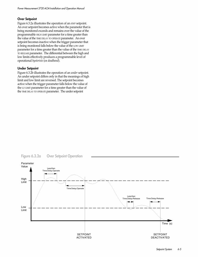
Power Measurement 3720 ACM Installation and Operation Manual
Setpoint System 6-5
Over SetpointFigure 6.3.2a illustrates the operation of an over setpoint.An over setpoint becomes active when the parameter that isbeing monitored exceeds and remains over the value of theprogrammable HIGH LIMIT parameter for a time greater thanthe value of the TIME DELAY TO OPERATE parameter. An oversetpoint becomes inactive when the trigger parameter thatis being monitored falls below the value of the LOW LIMIT
parameter for a time greater than the value of the TIME DELAY
TO RELEASE parameter. The differential between the high andlow limits effectively produces a programmable level ofoperational hysterisis (or deadband).
Under SetpointFigure 6.3.2b illustrates the operation of an under setpoint.An under setpoint differs only in that the meanings of highlimit and low limit are reversed. The setpoint becomesactive when the trigger parameter falls below the value ofthe LO LIMIT parameter for a time greater than the value ofthe TIME DELAY TO OPERATE parameter. The under setpoint
Time (s)
Less thanTime Delay Operate
SETPOINTACTIVATED
Time Delay Operate
Less thanTime Delay Release
SETPOINTDEACTIVATED
Time Delay Release
ParameterValue
HighLimit
LowLimit
Figure 6.3.2a Over Setpoint Operation

Power Measurement 3720 ACM Installation and Operation Manual
6-6 Setpoint System
becomes inactive when the parameter exceeds and remainsover the value of the HIGH LIMIT parameter for a time greaterthan the value of the TIME DELAY TO RELEASE parameter. Similarto over setpoint operation, the differential between the highand low limits produces an area of hysterisis.
6.3.3 ON/OFF & COUNTER SETPOINTS
Some trigger parameters provide a simple on or off condi-tion, such as phase reversal, or status input conditions. Forstatus input types, setpoints can monitor the condition ofindividual inputs (i.e. S1 ACTIVE, S2 NORMAL, etc.) or monitorall four status inputs together (i.e. SX ACTIVE). This second
Time Delay Operate
SETPOINTACTIVATED
SETPOINTDEACTIVATED
Time Delay Release
Time (s)
ParameterValue
HighLimit
LowLimit
Figure 6.3.2b Under Setpoint Operation

Power Measurement 3720 ACM Installation and Operation Manual
Setpoint System 6-7
method effectively operates as a Boolean “OR” function. For allon/off trigger parameters, the setpoint will become activewhen the defined condition becomes true. These triggerparameters do not use the HIGH or LOW LIMIT parameters.
Setpoints can also monitor status input counter totals. Thesetpoint will become active when the associated counterexceeds the total defined by the HIGH LIMIT parameter. Thesetrigger parameters do not use the LOW LIMIT parameter.
6.3.4 TIME-OVERCURRENT CURVE
NOTE
The Time-Overcurrent Curve (TOC) cannotbe used concurrently with the High-SpeedSnapshot Log (HSS) feature. You mustselect which feature to enable by setting theHIGH SPEED FEATURE parameter via communica-tions. To enable the Time-OvercurrentCurve, set it to TOC.
The 3720 ACM offers additional overcurrent protectioncapabilities using a programmable inverse time characteristic.Only the six high-speed setpoints can use this setpoint type.Virtually any time-current characteristic can be defined tomatch a wide range of applications.
The time-overcurrent curve represents a boundary for safecurrent operation of a feeder. The curve is represented bycurrent on the x-axis and time on the y-axis. The curve’s shapeis such that as the current increases, the time necessary to tripthe setpoint is reduced (see Figure 6.3.4). The amount of timerequired to trip the setpoint is configurable through selection ofthe proper data points.
NOTE
For accurate time-overcurrent responsetimes, the meter must provide adequatecurrent over-range capability to measure theexpected peak current. To provide this, themeter must be equipped with the correctover-range option. See Section 2.5.2.
Figure 6.3.4 Time-Overcurrent Curve
Power Measurement 3720 ACM Installation and Operation Manual
6-8 Setpoint System
Setpoint Active ConditionThe time-overcurrent setpoint operates similar to all othersetpoints. If the 3720 ACM measures a current that ismaintained for a period of time longer than is specified on thecharacteristic curve, the setpoint becomes active. This curve isbased on TIME versus XCURRENT multiplied by the MAX CURRENT (orpickup current). For example, in Figure 6.3.4 if the currentbecomes:
XCURRENT x MAX CURRENT
= 2.0 x 5000 = 10,000 Amps
the setpoint would take 5000 milliseconds to become active.
NOTE
Time-overcurrent calculations are based onthe high-speed setpoint system which pro-vides responses times in increments of 2cycles. Refer to Section 6.2.2 for minimumresponse times.
Setpoint Inactive ConditionAn inverse version of the time-overcurrent curve is used todetermine when the setpoint becomes inactive. This curve isbased on TIME versus the MAX CURRENT divided by the XCURRENT.For example, in Figure 6.3.4 if the current fell to:
MAX CURRENT / XCURRENT
= 5000/2.0 = 2500 Amps
the setpoint would take 5000 milliseconds to become inactive.
Additional Time DelaysThe programmable TIME DELAY TO OPERATE and RELEASE delays arestill operational for this setpoint type; however, it is notrecommended that they be used. Required delays should beimplemented using the characteristic time delays of the time-overcurrent curve. Using the TIME DELAY TO OPERATE and RELEASE
parameters to provide additional delays could produceunexpected results.
ProgrammingYou can program response curve parameters via the communi-cations port. POWER MEASUREMENT’s SCADA system provides asetup screen for the time-overcurrent curve. Specify the MAX
CURRENT parameter, then define the eight data points on thecurve using the y-axis coordinate XCURRENT and the x-axiscoordinate TIME parameters. Once the curve has been calculatedand displayed, it can be sent to the 3720 ACM via communica-tions and stored. To define a high-speed setpoint as a time-overcurrent type, set its TYPE parameter to TIME OVERCURRENT.
6.4 SETPOINT ACTIONS
6.4.1 INTRODUCTION
Action1 & Action2An active setpoint condition can be used to simultaneouslytrigger up to two separate actions. Each setpoint has twoprogrammable parameters which allow you to define eachaction. These are named ACTION1 and ACTION2.
NOTE
If ACTION1 and ACTION2 are both configuredfor a setpoint, ACTION1 is always performedfirst.
Action TypesFor each setpoint action, many action types are available.
The eleven standard setpoints can be used to trigger:
• Relay control
• Waveform capture
• Waveform recording
• Snapshot logging (standard only)
• Clearing functions:- clearing the Min/Max Logs (preset and/or
programmable)- clearing the status counters (one or all)- resetting the TOU energy registers and/or TOU
demand registers.
The six high-speed setpoints can trigger:
• Relay control
• Waveform capture
• Waveform recording
• Snapshot logging (high-speed only)
• Clearing functions:- clearing the status counters (one or all).
ProgrammingACTION1 and ACTION2 for each setpoint are both programmablevia communications. The following sections describe eachsetpoint action in detail.

Power Measurement 3720 ACM Installation and Operation Manual
Setpoint System 6-9
6.4.2 RELAY CONTROL
Any of the three on-board relays of the 3720 ACM can beautomatically controlled by a high-speed or standard setpoint.Setpoint-controlled relays can perform a wide range ofoperations, including:
• Shunt tripping a breaker
• Activating an alarm buzzer or light
• Controlling an external piece of equipment.
NOTE
Refer to Sections 6.2.2 and 6.2.3 for infor-mation regarding setpoint and relay re-sponse times and other considerations.
A relay assigned to a setpoint is automatically operated whenthe setpoint becomes active, and released when the setpointreturns to its inactive state.
ProgrammingTo configure a setpoint for relay control, you must program theparameters for both the setpoint and for the assigned relay:
• Set the ACTION1 or ACTION2 parameter to the desired relay.
• The MODE parameter for the assigned relay must bedefined as SETPOINT.
The programmable TIME DELAY TO OPERATE delay can be used todelay a setpoint from becoming active, thus delaying when theassigned relay is operated. The programmable TIME DELAY TO
RELEASE delay can be used to delay when the setpoint returns toits inactive state, thus delaying when the assigned relay isreleased.
Avoiding Operational ConflictsAs described in Chapter 3, relays may also be used for kWH,kVARH, or kVAH pulsing. Take care that a relay configuredfor hour pulsing is not also assigned to setpoint operation.Pulsing operations always override setpoint control.
Multi-Level and Multi-Function Relay ControlThe 3720 ACM setpoint system allows for multi-level andmulti-function relay control operations. The following ex-amples illustrate this flexibility.
EXAMPLES1. By assigning the same relay number to more than
one setpoint, multiple setpoints can be channelled to asingle relay. This feature can effectively produce aBoolean “OR” function. This also allows a single relay toperform multiple functions; however, as mentioned above,care must be taken to avoid operational conflicts.
2. You wish to configure a two-level relay protection scheme.First assign two setpoints to monitor the same triggerparameter (i.e. OVER CURRENT). Set each setpoint to triggeron a different parameter limit, one higher than the other(i.e. H01 HI LIMIT = 500, H02 HI LIMIT = 750). Configure eachsetpoint to control a different relay (i.e. H01 ACTION1 =RELAY1, H02 ACTION1 = RELAY2). Each relay could control adifferent external protection device. As the value of themeasured parameter increases, each relay will trip insequence.
Manual Forced Relay OverrideA relay configured for setpoint control (MODE = SETPOINT) may beforced operated or released using commands issued viacommunications. Manual commands override any presentsetpoint-controlled relay operations. Once a command toreturn to normal is issued via communications, the affectedrelay is immediately returned to setpoint control.
6.4.3 WAVEFORM CAPTURE TRIGGERING
Any of the standard or high-speed setpoints can be used totrigger the waveform capture functions. Setpoint triggeredwaveform capture allows the 3720 ACM to automaticallyperform a high-resolution capture of one cycle of a singleselected input. Input options include any one of the six phasevoltage and current inputs, I4 (neutral) input, or Vaux input.This data can be uploaded to POWER MEASUREMENT’s SCADAsoftware to facilitate analysis of the harmonic content whichexisted coincident with the fault condition defined by thesetpoint. This is described in more detail in Chapter 6.
ProgrammingTo configure a setpoint condition to trigger waveform capture,the user must program one of the setpoint’s two ACTION
parameters as WAVE CAPTURE xx, where xx represents the specificinput to be captured (V1, I1, etc.)
The programmable TIME DELAY TO OPERATE delay can be used toprovide a delay interval between when the setpoint becomesactive and when waveform capture is triggered. The TIME DELAY
TO RELEASE parameter has no effect.
Manual Trigger OverrideA waveform capture trigger command received via communi-cations overrides any setpoint controlled waveform captureaction. Once the capture data has been uploaded via commu-nications, the recorder automatically re-arms and returns tosetpoint control.
6.4.4 WAVEFORM RECORDER TRIGGERING
Power Measurement 3720 ACM Installation and Operation Manual
6-10 Setpoint System
Any of the standard or high-speed setpoints can be used totrigger the waveform recording function. Waveform recordingcan provide a detailed 12 to 36-cycle record of all input signalsbefore, during, and after the occurrence of a fault. Inputsinclude all six phase voltage and current inputs, plus the I4(neutral) and VAUX inputs.
The recorder can be configured to store three 12-cycle events,two 18-cycle events, or one 36-cycle event on-board for allinputs. The waveform recorder runs continuously until it istriggered either by a setpoint event or manually by a commandissued via communications. At that time the waveform data isfrozen in memory. This is described in more detail in Chapter7.
ProgrammingTo configure a setpoint condition to trigger waveform record-ing, you must program one of the setpoint’s two ACTION
parameters to WFR.
The programmable TIME DELAY TO OPERATE delay can be used todelay a setpoint from becoming active, thus delaying thetriggering of the waveform recorder. This is described in detailin Chapter 7. The TIME DELAY TO RELEASE parameter can be used todelay when the setpoint becomes inactive, but this has no effecton waveform recorder triggering.
Manual Trigger OverrideA waveform recorder trigger command received via communica-tions overrides any setpoint controlled waveform recorder action.Once the recorded data is uploaded via communications, therecorder automatically re-arms and returns to setpoint control.
6.4.5 SNAPSHOT LOG TRIGGERING
Triggering of Snapshot Logs using setpoints allows you todefine groups of important measured parameters or statusinformation whose values or conditions are logged when asetpoint becomes active. The Snapshot Log records all user-defined parameters with a time-stamp. This can providedetailed operations information to aid in isolating problemsources.
Any of the eleven standard setpoints can be programmed totrigger any of the eight standard Snapshot Logs. Only high-speed setpoints can be programmed to trigger a high-speedSnapshot Log, if one has been configured.
Snapshot Logs can be triggered by setpoints in one of twoways:
ONE SHOTIf the Snapshot Log’s programmable INTERVAL parameter isset to 0 seconds, the log records once when the setpointcondition initially occurs.
GATEDIf the programmable INTERVAL parameter is set to a non-zero time interval, the Snapshot Log records once when thesetpoint condition initially occurs, and continues to recordat the specified intervals the entire time the setpointremains in an active condition.
Note that a high-speed Snapshot Log operates differently thana standard log, using an additional user-defined stop condition.This is described in more detail in Chapter 8.
ProgrammingSetpoint parameters related to snapshot logging are notaccessible via the front panel of the 3720 ACM. To configure asetpoint condition to trigger a Snapshot Log, you mustprogram the setpoint via communications. One of thesetpoint’s two ACTION parameters must be set to SLx, where xrepresents the standard Snapshot Log number (1 to 8), or to HSS
for the high-speed Snapshot Log, if configured.
The programmable TIME DELAY TO OPERATE delay can be used todelay a setpoint from becoming active, thus delaying thetriggering of the Snapshot Log. The TIME DELAY TO RELEASE
parameter can be used to delay when the setpoint becomesinactive, but this has no effect on Snapshot Log triggering.
Application ExampleSetpoint triggered snapshot logging is ideal for saving criticalinformation prior to the clearing of registers or logs. Forexample, suppose a standard setpoint is configured to triggeron NEW HOUR, DAY, MONTH or YEAR. To save the current values ofthe TOU registers or min/max parameters, assign thoseparameters of interest to a standard Snapshot Log, thenconfigure the log to be one-shot triggered by the setpoint. Thefirst action of the setpoint would be to trigger the log. Thesecond action would be to clear the TOU registers, or Min/MaxLog. Each time a new month occurs, for example, the currentdata is saved, and the parameters are reset. See Section 6.4.6for information on clearing registers and logs.
NOTE
As mentioned in Section 5.4.1, the ACTION1 ofany setpoint is always performed beforeACTION2. Therefore it is very important thatACTION1 performs the Snapshot Log trigger,while ACTION2 performs the subsequent clear-ing function. Otherwise the current datawill always be lost.
6.4.6 CLEARING FUNCTIONS
Preset and programmable Min/Max Logs, TOU registers andcounters can be cleared automatically using setpoints. Refer toFigure 3.4.6f for a detailed list of the clearing functions you canassign to a setpoint-triggered action.
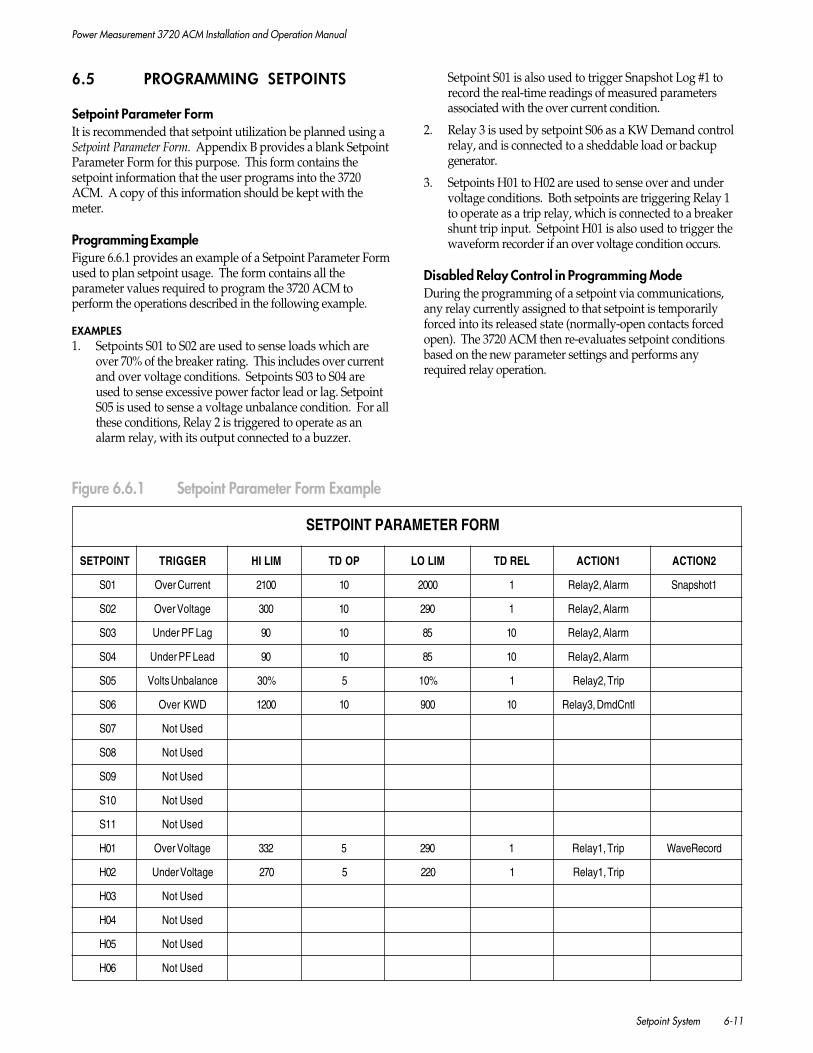
Power Measurement 3720 ACM Installation and Operation Manual
Setpoint System 6-11
6.5 PROGRAMMING SETPOINTS
Setpoint Parameter FormIt is recommended that setpoint utilization be planned using aSetpoint Parameter Form. Appendix B provides a blank SetpointParameter Form for this purpose. This form contains thesetpoint information that the user programs into the 3720ACM. A copy of this information should be kept with themeter.
Programming ExampleFigure 6.6.1 provides an example of a Setpoint Parameter Formused to plan setpoint usage. The form contains all theparameter values required to program the 3720 ACM toperform the operations described in the following example.
EXAMPLES1. Setpoints S01 to S02 are used to sense loads which are
over 70% of the breaker rating. This includes over currentand over voltage conditions. Setpoints S03 to S04 areused to sense excessive power factor lead or lag. SetpointS05 is used to sense a voltage unbalance condition. For allthese conditions, Relay 2 is triggered to operate as analarm relay, with its output connected to a buzzer.
Figure 6.6.1 Setpoint Parameter Form Example
Setpoint S01 is also used to trigger Snapshot Log #1 torecord the real-time readings of measured parametersassociated with the over current condition.
2. Relay 3 is used by setpoint S06 as a KW Demand controlrelay, and is connected to a sheddable load or backupgenerator.
3. Setpoints H01 to H02 are used to sense over and undervoltage conditions. Both setpoints are triggering Relay 1to operate as a trip relay, which is connected to a breakershunt trip input. Setpoint H01 is also used to trigger thewaveform recorder if an over voltage condition occurs.
Disabled Relay Control in Programming ModeDuring the programming of a setpoint via communications,any relay currently assigned to that setpoint is temporarilyforced into its released state (normally-open contacts forcedopen). The 3720 ACM then re-evaluates setpoint conditionsbased on the new parameter settings and performs anyrequired relay operation.
SETPOINT PARAMETER FORM
SETPOINT TRIGGER HI LIM TD OP LO LIM TD REL ACTION1 ACTION2
S01 Over Current 2100 10 2000 1 Relay2, Alarm Snapshot1
S02 Over Voltage 300 10 290 1 Relay2, Alarm
S03 Under PF Lag 90 10 85 10 Relay2, Alarm
S04 Under PF Lead 90 10 85 10 Relay2, Alarm
S05 Volts Unbalance 30% 5 10% 1 Relay2, Trip
S06 Over KWD 1200 10 900 10 Relay3, DmdCntl
S07 Not Used
S08 Not Used
S09 Not Used
S10 Not Used
S11 Not Used
H01 Over Voltage 332 5 290 1 Relay1, Trip WaveRecord
H02 Under Voltage 270 5 220 1 Relay1, Trip
H03 Not Used
H04 Not Used
H05 Not Used
H06 Not Used

Power Measurement 3720 ACM Installation and Operation Manual
6-12 Setpoint System
6.6 POWER OUTAGES
When the power feed to the 3720 ACM is interrupted, evenmomentarily, the output relays release. When power isrestored, the 3720 ACM allows a 3 second settling time. Afterthis interval the setpoint conditions are re-evaluated and, ifappropriate, the relays operate after the programmed timedelays.
If any relay has been forced operated or forced released usingcommands issued via the communications port prior to thepower outage, it is released when the outage occurs. Whenpower is restored, the 3720 ACM resumes normal setpointoperation as described above. Relays will not automaticallyreturn to a forced operated or forced released conditionfollowing a power outage.

Power Measurement 3720 ACM Installation and Operation Manual
Waveform Capture & Waveform Recorder 7-1
7 WAVEFORM CAPTURE &RECORDING
7.1 INTRODUCTION
The 3720 ACM is equipped with digital waveform samplingcapabilities. The 3720 ACM provides two powerful methodsfor acquiring waveform data: waveform capture and waveformrecording. Waveform capture can be used for detailed powerquality analysis beyond that offered by the on-board harmon-ics measurements. Waveform recording can assist in analyz-ing short duration events such as faults, surges, etc.
Waveform capture and recording are independent functionsand can be used concurrently. Each function can be indepen-dently triggered by a user-defined setpoint condition or by acommand issued via communications.
7.2 WAVEFORM CAPTURE
7.2.1 THE IMPORTANCE OF POWER QUALITYMONITORING
Power quality has become a foremost concern for powerutilities and their customers due to an increasing presence ofinduced harmonic voltages and currents in industrial,commercial and residential electrical supplies. Harmonics aretypically generated within a facility’s power distributionsystem by non-linear loads (variable frequency drives, UPSsystems, HVAC and lighting systems, computers, etc.)
Poor power quality can have serious and potentially damag-ing consequences, including equipment malfunctions orfailures, reduced efficiency and mechanical vibration inmotors, or incorrect tripping and/or failure of circuit breakers.Harmonic currents from individual phases can also add in theneutral line, sometimes producing dangerously high neutralcurrents.
As harmonic sources become more prevalent, it is importantto have the analytical tools necessary to identify potentialproblem sources and help in determining the preventative orcorrective measures necessary to improve power quality inelectrical distribution systems.
7.2.2 USING CAPTURED DATA
Waveform capture allows you to perform high-speed sam-pling of the V1, V2, V3, VAUX, I1, I2, I3, or I4 (neutral current)inputs. One full cycle of the signal at a single selected input issampled at a rate of 128 samples per cycle. All samples aretaken synchronous to the line frequency and within one inputcycle.
Sampled waveform data is stored in on-board memory andcan be read via the communications port. The high samplingrate used by the 3720 ACM produces high-resolution datawhich allows analysis of frequency components to the 63rdharmonic.
POWER MEASUREMENT’s SCADA software can be used toupload captured waveform data from the 3720 ACM to amaster computer station and display the waveforms on thecomputer screen (see Figure 7.2.2a). The SCADA softwareautomatically performs a Fast Fourier Transformation on eachwaveform, and provides an indication of total harmonicdistortion and a breakdown of individual frequency compo-nents both in graphical (Figure 7.2.2b) and tabular form(Figure 7.2.2c) to the 63rd harmonic. This wide variety ofdata formats can help you quickly pinpoint the source andseverity of harmonics, evaluate which sources must beminimized, and develop corrective strategies.
7.2.3 TRIGGERING FROM A SETPOINT
Triggering waveform capture from a setpoint allows you toanalyze the harmonic character of any single selected voltageor current input which existed coincidental with the user-defined setpoint condition. An example might be a powerline fault condition which is being produced by high har-monic content.
Triggering can be performed by either a high-speed or stan-dard type setpoint. The user must set the programmableACTION1 or ACTION2 parameter for the selected setpoint toWAVE CAPTURE. This parameter option must be programmedvia communications. You must also select the input that is tobe captured (V1, V2, V3, VAUX, I1, I2, I3, I4).
The TIME DELAY TO OPERATE parameter can be used to providean additional delay before the setpoint becomes active, thusdelaying when waveform capture is triggered. The TIME DELAY
TO RELEASE parameter has no effect.
When the setpoint becomes active (following any pro-grammed time delay), waveform capture is automaticallyinitiated on the selected input and the data is held inmemory. No subsequent capture actions are allowed untilthe currently stored data is read via communications, andwaveform capture has been rearmed.
If the 3720 ACM is being used with the SCADA software, thecomputer station senses when the setpoint condition andsubsequent waveform capture triggering occurs. The captureddata is then automatically uploaded to the computer alongwith its time stamp. The SCADA software automaticallyrearms the waveform capture feature after the data has beenuploaded. The SCADA software’s waveform capture screencan be used to retrieve one or more captured waveforms fromthe hard disk and display them graphically with the timestamp and an indication of the trigger source.
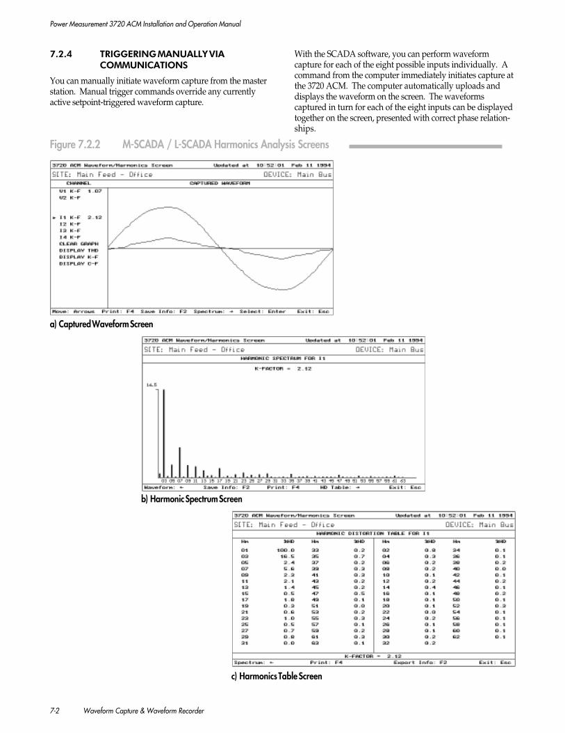
Power Measurement 3720 ACM Installation and Operation Manual
7-2 Waveform Capture & Waveform Recorder
7.2.4 TRIGGERING MANUALLY VIACOMMUNICATIONS
You can manually initiate waveform capture from the masterstation. Manual trigger commands override any currentlyactive setpoint-triggered waveform capture.
With the SCADA software, you can perform waveformcapture for each of the eight possible inputs individually. Acommand from the computer immediately initiates capture atthe 3720 ACM. The computer automatically uploads anddisplays the waveform on the screen. The waveformscaptured in turn for each of the eight inputs can be displayedtogether on the screen, presented with correct phase relation-ships.
Figure 7.2.2 M-SCADA / L-SCADA Harmonics Analysis Screens
a) Captured Waveform Screen
b) Harmonic Spectrum Screen
c) Harmonics Table Screen

Power Measurement 3720 ACM Installation and Operation Manual
Waveform Capture & Waveform Recorder 7-3
7.3 WAVEFORM RECORDING
7.3.1 USING RECORDED DATA
Power line faults, surges, sags, or other disturbances cancause expensive service interruptions. The 3720 ACMwaveform recording feature is ideal for fault and surgeanalysis, and to aid in fault location. It provides a powerfulmethod for analyzing the conditions occurring before, during,and after a power fluctuation or failure. For example, faultrecording can be performed by triggering on a status inputsetpoint which is monitoring a breaker trip. Other applica-tions include the recording of voltage or current transients,transformer inrush currents, or motor start-up currents.
Waveform recording allows for simultaneous 12, 18, or 36-cycle sampling of all eight voltage and current inputs at a rateof 16 samples per cycle. The recorder runs continuously untiltriggered by a user-specified setpoint condition or by amanual command made via communications. You can alsoset a programmable trigger delay, which allows you to definethe amount of pre-event and post-event waveform data to becaptured.
POWER MEASUREMENT’s SCADA software can be used todisplay one or more of the eight recorded waveforms on thecomputer screen. The waveforms for single inputs or groupsof inputs can be displayed together, presenting a comprehen-sive picture of the power line conditions surrounding thedisturbance (see Figure 7.3.1). The screen provides zoom andpan capabilities, as well as a set of movable cursors that canhelp quickly pinpoint the absolute and relative times ofwaveform characteristics.
7.3.2 CONFIGURING THE RECORDER
The on-board memory of the 3720 ACM can store a total of 36cycles of waveform data for each input. This memory spacecan be configured to store single or multiple events. Choicesare:
• 3x12. Three 12-cycle events.
• 2x18. Two 18-cycle events.
• 1x36. One 36-cycle event.
You must program the WFR CONFIGURATION parameter viacommunications to select one of the options above.
Choosing either the 3x12 or 2x18 multiple waveform configu-ration allows the 3720 ACM to record many events that maybe close together in time. In the case of the 3x12 option, up to3 events could be stored on-board until uploaded to thecomputer.
The 1x36 configuration is ideal for recording events of longerduration; however, it is recommended this option not be usedif events are expected to be close together. For example, arecloser activation may generate multiple, closely spacedcontact closures.
Figure 7.3.1 M-SCADA / L-SCADA Waveform Recorder Screen
Power Measurement 3720 ACM Installation and Operation Manual
7-4 Waveform Capture & Waveform Recorder
7.3.3 TRIGGERING FROM A SETPOINT
ProgrammingTriggering can be performed by either a high-speed or stan-dard type setpoint. You must set the programmable ACTION1or ACTION2 parameter for the selected setpoint to WFR. Thisparameter option must be programmed via communications.
As described in Section 6.4.4, the programmable TIME DELAY TO
OPERATE delay can be used to delay a setpoint from becomingactive, thus delaying the triggering of the waveform recorder(see Section 7.3.4). The TIME DELAY TO RELEASE parameter canbe used to delay when the setpoint becomes inactive, but thishas no effect on waveform recorder triggering.
OperationThe waveform recorder runs continuously until it is triggeredby the setpoint event. When the setpoint becomes active, thewaveform recorder is triggered (following any programmedtime delay) and the window of cycles (i.e. 12, 18, or 36) ofeach input are frozen in memory along with a time stamp.
The waveform recorder is automatically rearmed so thatsuccessive recordings can occur until all of the recordermemory has been filled. This would occur after the thirdrecording of 12 cycles for the 3x12 configuration, or after thesecond recording for the 2x18 configuration. The memory isalways filled after the single recording for the 1x36 cycleconfiguration .
NOTE
To avoid duplication of waveform data,recorder triggers must be at least 2 cyclesapart. Following the initial trigger, all sub-sequent triggers within a 2-cycle period willbe ignored.
Once the recorder memory is filled, the recorder is disarmed.All subsequent setpoint triggers are ignored until the currentlystored data is read via communications. Manual triggercommands can override this (see Section 7.3.4). The recorderis rearmed automatically following transfer of the waveformrecorder data.
Using the SCADA software, the master station automaticallyidentifies if the waveform recorder is currently storing one ormore recorded events. If so, all recorded events for all inputsare uploaded to the computer along with their time stampand archived to the hard disk.
The SCADA software’s waveform recorder screen can be usedto retrieve one or more channels of each recorder event fromthe hard disk and graphically display them with the timestamp, an indication of the trigger source, and the location ofthe trigger point on the waveform(s).
7.3.4 ADJUSTING THE TRIGGER POINTPRE-EVENT & POST-EVENT DATA
Using high-speed setpoints to trigger the waveform recorder,you are able to acquire both pre-event data and post-eventdata. If the programmable TIME DELAY TO OPERATE parameteris set at zero (the default), the time that the setpoint eventoccurred will exist within the window of cycles recorded bythe waveform recorder (see Figure 7.3.4, Example 1).
The recorder exhibits an inherent trigger delay of up to 2 cyclesbetween when the external or internal setpoint event occursand the setpoint has been fully evaluated. The best case is forthis delay 1 cycle. At this point the setpoint performs theaction of freezing the waveform recorder. This processexhibits an additional stop delay of up to 2 cycles. In total, thiscan provide up to 4 cycles of post-event data, without theaddition of a user-programmable delay (as described below).
Using standard setpoints to trigger the waveform recorderprovides a much slower response. This slower responseallows the waveform recorder to provide only post-event data.The time that the event occurred could exist 1 to 2 secondsprior to the start of the window of cycles recorded by thewaveform recorder.
NOTE
When using high-speed or standardsetpoints to trigger the waveform recorder,the actual trigger point depends on thetype of setpoint parameter being monitored(i.e. under voltage, status input change,etc.) and the additional programmable de-lay that you define.
Using Programmable DelaysThe TIME DELAY TO OPERATE parameter can be used to vary theamount of pre-event and post-event data recorded by thewaveform recorder.
If a high-speed setpoint is being used to trigger the waveformrecorder, the TIME DELAY TO OPERATE parameter can be used toprovide additional cycles of post-event data. The setpointevent time will effectively be moved earlier within the windowof recorded cycles, reducing the amount of pre-event data andincreasing the amount of post-event data.
Figure 7.3.4, Example 2 shows how setting TIME DELAY TO
OPERATE = 2 (cycles) can cause the trigger point to be dis-placed by 2 cycles later in time, making the location of thesetpoint event 2 cycles earlier in the window of recordedcycles. Note that the TIME DELAY TO OPERATE is added to the 4cycle (worst case) total inherent trigger and stop delay of therecorder.

Power Measurement 3720 ACM Installation and Operation Manual
Waveform Capture & Waveform Recorder 7-5
EXAMPLE 1
High Speed Setpoint.12-cycle recording example.TIME DELAY TO OPERATE = 0 cycles
1 2 3 4 5 6 7 8 9 10 11 12
TIME
EXAMPLE 2
High Speed Setpoint.12-cycle recording example.TIME DELAY TO OPERATE = 2 cycles
PRE-EVENT DATA
Figure 7.3.4 Waveform Recorder High-Speed Trigger Point Adjustment
1 2 3 4 5 6 7 8 9 10 11 12
TIME
Worst-CaseStop Delay= 2 cycles
Worst-CaseInherent Delay
= 2 cycles
SETPOINTEVENT
POST-EVENT DATAPRE-EVENT DATA
TRIGGERPOINT
RECORDER ISFROZEN
Worst-CaseInherent Delay
= 2 cycles
SETPOINTEVENT
POST-EVENT DATA
User-definedTime Delay= 2 cycles
Worst-CaseStop Delay= 2 cycles
TRIGGERPOINT
RECORDER ISFROZEN

Power Measurement 3720 ACM Installation and Operation Manual
7-6 Waveform Capture & Waveform Recorder
NOTE
As mentioned in Section 6.3.2, for asetpoint to become active, the active condi-tion must exist for a period greater thanthe value of the TIME DELAY TO OPERATE pa-rameter. Therefore, no additional program-mable delays should be applied when us-ing the waveform recorder to captureevents of short duration (2 to 6 cycles).Otherwise, the recorder may fail to trigger.
Adding a large delay causes the setpoint event time to existoutside of the window of recorded cycles, causing the recorderto provide only post-event data.
As mentioned previously, if a standard setpoint is being usedto trigger the waveform recorder, the cycles recorded willalways be post-event data. The TIME DELAY TO OPERATE
parameter can be used to shift this window later in time, inincrements of seconds.
7.3.5 TRIGGERING MANUALLY VIACOMMUNICATIONS
You can manually trigger waveform recording via the commu-nications port. Using the SCADA software, you can manu-ally initiate waveform recording from the master station. Acommand from the computer immediately initiates capture atthe 3720 ACM, and the data is subsequently uploaded. TheTIME DELAY TO OPERATE parameter has no effect on manualtriggering.
Manual trigger commands override any currently activesetpoint triggered waveform recording.

Power Measurement 3720 ACM Installation and Operation Manual
On-Board Data Logging 8-1
8 ON-BOARD DATA LOGGING
8.1 INTRODUCTION
Data logging can be extremely useful in the study of growthpatterns, for scheduling loads and for cost allocation, forisolating problem sources, or for analyzing a variety of powersystem operating conditions.
The 3720 ACM supports three types of on-board datalogging:
• Event Log
• Minimum / Maximum Logs- 1 Preset (Master)- 16 Programmable
• Programmable Snapshot Logs- 8 Standard, one of which can be assigned as
High-Speed
All logged data is stored in internal non-volatile memory andis accessible via the communications port. Measured valuesfrom the Preset Min/Max Log are also accessible from thefront panel of the 3720 ACM. These parameters must beassigned to the GROUP buttons (see Chapter 3).
8.2 EVENT LOG
The Event Log records automatically the 100 most recentevents. A wide variety of event types are recorded by this log:
• Power-up and power-down activity.
• Setpoint (alarm) conditions.
• Relay activity. This includes operate/release actionstriggered by setpoints or manually via communica-tions.
• Status input activity. If desired, the logging of statusinput activity can be enabled via communications.
• Triggering of the waveform capture, waveform re-corder, and snapshot logging features. This includeswaveform functions triggered by setpoints andsnapshot logging functions triggered by setpoints.
• Changes made to the user-programmable parametersfrom the front panel or via communications.
• Self-diagnostic events.
The Event Log can be used to record a complete sequence-of-events record for breaker and transfer switch operations,alarm conditions, and equipment starts and stops.

Power Measurement 3720 ACM Installation and Operation Manual
8-2 On-Board Data Logging
Figure 8.2.1 illustrates a typical 3720 ACM Event Log dis-played by POWER MEASUREMENT’s SCADA software. Themost recent events are found at the top of the log screen.
Note that when a setpoint is programmed to trigger an action(relay control, waveform recording, etc.), the setpoint activa-tion and the subsequent setpoint action are logged separately.
For example, the highlight bar in Figure 8.2.1 is located on anevent that describes the standard setpoint S03 going into anactive state and triggering a reset of all TOU demand registers(RESET TOU DMD ALL). This is one of two setpoint actions thatoccurred. The first action can be seen directly below, whereSnapshot Log 2 was triggered (SL2 TRIGGERED). The actualsetpoint condition that caused the setpoint to go into anactive state can be found directly below that record. It showsthat new day setpoint event (NEW DAY) occurred and trig-gered, which in turn activated Standard Setpoint 3 (SETPOINT
S03 ACTIVE). Each subsequent action performed due to asingle setpoint activation is recorded separately in the EventLog.
Each event record stored in the Event Log includes:
CauseThis identifies the setpoint condition that activated ordeactivated a setpoint, a user action (such as device program-ming), or any other event type that occurred.
(Cause) ValueIf the event was a setpoint being activated or deactivated, thevalue of the measured parameter that triggered the setpoint isrecorded. If a setpoint action is being logged, the new state ofthe setpoint is recorded.
EffectIf the event was a setpoint being activated or deactivated, thesetpoint is identified. If a setpoint action is being logged, theaction taken is identified. If any other type of event occurred,it is described.
(Effect) ValueIf the event was a setpoint being activated or deactivated, thenew state of the setpoint is recorded.
Date & TimeThe event is date and time-stamped. The date provides theyear, month, and day. Event times are recorded in hours,minutes, seconds and milliseconds. Logged time-stamps areprovided with millisecond resolution; however, time accura-cies vary depending on the type of parameter being loggedand other factors. Refer to Section 8.6 for more information.
Figure 8.2.1 M-SCADA Event Log Screen
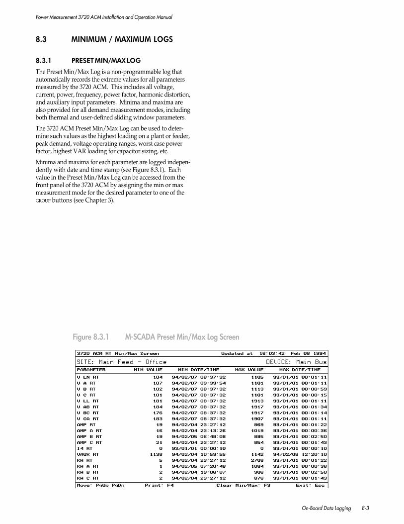
Power Measurement 3720 ACM Installation and Operation Manual
On-Board Data Logging 8-3
8.3 MINIMUM / MAXIMUM LOGS
8.3.1 PRESET MIN/MAX LOG
The Preset Min/Max Log is a non-programmable log thatautomatically records the extreme values for all parametersmeasured by the 3720 ACM. This includes all voltage,current, power, frequency, power factor, harmonic distortion,and auxiliary input parameters. Minima and maxima arealso provided for all demand measurement modes, includingboth thermal and user-defined sliding window parameters.
The 3720 ACM Preset Min/Max Log can be used to deter-mine such values as the highest loading on a plant or feeder,peak demand, voltage operating ranges, worst case powerfactor, highest VAR loading for capacitor sizing, etc.
Minima and maxima for each parameter are logged indepen-dently with date and time stamp (see Figure 8.3.1). Eachvalue in the Preset Min/Max Log can be accessed from thefront panel of the 3720 ACM by assigning the min or maxmeasurement mode for the desired parameter to one of theGROUP buttons (see Chapter 3).
Figure 8.3.1 M-SCADA Preset Min/Max Log Screen
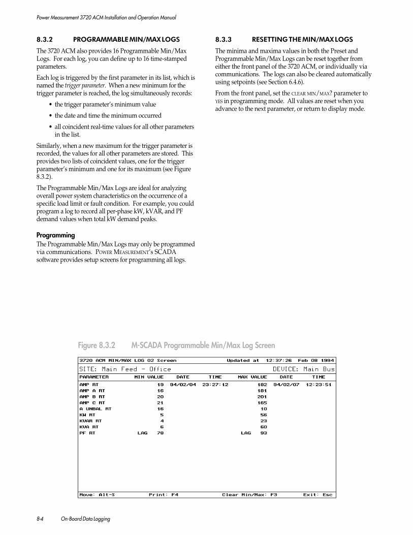
Power Measurement 3720 ACM Installation and Operation Manual
8-4 On-Board Data Logging
8.3.2 PROGRAMMABLE MIN/MAX LOGS
The 3720 ACM also provides 16 Programmable Min/MaxLogs. For each log, you can define up to 16 time-stampedparameters.
Each log is triggered by the first parameter in its list, which isnamed the trigger parameter. When a new minimum for thetrigger parameter is reached, the log simultaneously records:
• the trigger parameter’s minimum value
• the date and time the minimum occurred
• all coincident real-time values for all other parametersin the list.
Similarly, when a new maximum for the trigger parameter isrecorded, the values for all other parameters are stored. Thisprovides two lists of coincident values, one for the triggerparameter’s minimum and one for its maximum (see Figure8.3.2).
The Programmable Min/Max Logs are ideal for analyzingoverall power system characteristics on the occurrence of aspecific load limit or fault condition. For example, you couldprogram a log to record all per-phase kW, kVAR, and PFdemand values when total kW demand peaks.
ProgrammingThe Programmable Min/Max Logs may only be programmedvia communications. POWER MEASUREMENT’s SCADAsoftware provides setup screens for programming all logs.
8.3.3 RESETTING THE MIN/MAX LOGS
The minima and maxima values in both the Preset andProgrammable Min/Max Logs can be reset together fromeither the front panel of the 3720 ACM, or individually viacommunications. The logs can also be cleared automaticallyusing setpoints (see Section 6.4.6).
From the front panel, set the CLEAR MIN/MAX? parameter toYES in programming mode. All values are reset when youadvance to the next parameter, or return to display mode.
Figure 8.3.2 M-SCADA Programmable Min/Max Log Screen

Power Measurement 3720 ACM Installation and Operation Manual
On-Board Data Logging 8-5
8.4 PROGRAMMABLE SNAPSHOT LOGS
8.4.1 INTRODUCTION
3720 ACM Snapshot Logs are historical or trend logs. Up to 8standard logs may be defined. Snapshot Log 8 can be alterna-tively configured as a high-speed log. Each standard or high-speed log can record up to 12 channels of data (see Figure8.4.1). Each snapshot record is stored with a date and time-stamp. This can provide you with detailed operationsinformation to aid in isolating problem sources.
Each Snapshot Log can be independently triggered either on auser-defined time interval basis, or from a setpoint.
Snapshot Logs can be used to replace traditional strip chartrecorders. Data collected by the logs can be used to producedaily/weekly/monthly load profile graphs for power, de-mand, power factor, etc. Data can also be used for time-of-use or billing calculations.
The following section describes the configuration and opera-tion of standard and high-speed Snapshot Logs. All configu-ration must be performed via communications.
Figure 8.4.1 M-SCADA Standard Snapshot Log Screen
8.4.2 MEMORY ALLOCATION
The large capacity of the 3720 ACM on-board memoryallocated to snapshot logging is partitioned between theindividual Snapshot Logs you programmed.
The amount of memory space each Snapshot Log requiresdepends on the number of parameters (channels) beinglogged, the type of parameters being logged (some parametersare not compressible), the maximum number of snapshotrecords stored, and whether the log is triggered by timeinterval or setpoint. Triggering is described in the followingsections. Setpoint-triggered snapshots require somewhatmore memory than interval-triggered snapshots.
The number of Snapshot Logs, number of parameters per log,triggering method, time intervals (if interval triggered) andtotal number of records per log can be set to make best use ofthe available memory for the specific application(s).
The parameters that cannot be compressed include KWh,KVAh, KVARh, time values, various status registers andscalable status input counters. All other parameters can becompressed. If the parameters you wish to log are compress-ible, you will be able to store more records. Note that com-pression is not used for the high-speed log.
Figure 8.4.2 illustrates how various log assignments havedifferent memory requirements. All logs in the example areinterval-triggered.
POWER MEASUREMENT's SCADA software allows you to definethe maximum 3720 ACM memory space used by each log as apercentage of the total available space. To help you decide onthe amount of memory to allocate to each log, the SCADAsoftware provides a Maximum Remaining Memory indicatorin percent. The screen also provides a value indicating themaximum number of records that can be stored by the logusing the present settings. Increasing the memory allocationincreases the number of records possible. Conversely,increasing the number of parameters logged decreases thenumber of records possible.

Power Measurement 3720 ACM Installation and Operation Manual
8-6 On-Board Data Logging
Figure 8.4.2 Snapshot Log Capacity Examples - Interval Triggered
SETPOINTStandard Snapshot Logs may also be triggered by any of theeleven standard setpoints. This method of triggering a log isideal for analyzing system conditions which occur periodicallydue to faults, power fluctuations, or other events (breaker trip,etc.) Setpoint conditions can include harmonic distortionlevels, status input changes, and more (see Chapter 6). High-speed setpoints cannot be used for this purpose.
To set a log for setpoint triggering, the programmable TRIGGER
TYPE parameter must be set to SETPOINT. The ACTION1 orACTION2 for the standard setpoint used must be configured asSNAPSHOT x (where x = 1 to 8).
Logs can be triggered by setpoints in one of two ways:
• One Shot. If the programmable INTERVAL parameter isset to 0 seconds, the Snapshot Log records once whenthe setpoint condition initially occurs (see Figure8.4.3b).
• Gated. If the programmable INTERVAL parameter is set toa non-zero time interval, the Snapshot Log recordsonce when the setpoint condition initially occurs, andcontinue to record at the specified intervals during theentire time that the setpoint remains in an activecondition (see Figure 8.4.3b). This effectively producesa window of snapshot records. Subsequent triggerscauses successive windows of snapshot records to bestored. This method makes very efficient use of thesnapshot memory, since logging occurs only duringperiods of interest.
8.4.3 STANDARD SNAPSHOT LOGS
Up to 8 standard Snapshot Logs can be defined. Note thatthe HIGH SPEED FEATURE parameter must be set to TOC forSnapshot Log 8 to be configured as a standard log. SeeSection 8.4.4 below for more information.
Logged ParametersThe parameter recorded by each channel of a log is user-programmable. The values of any real-time parameter, energyparameter, status parameter, or TOU register can be logged.Chapters 4 and 5 list these parameters. High-speed param-eters can only be logged by a high-speed log (see Section8.4.4).
Triggering
TIME INTERVALTime interval triggering allows a Snapshot Log to run con-tinuously, automatically recording all channels of data atuser-defined time intervals. To set a log for interval triggering,the programmable TRIGGER TYPE parameter must be set toINTERVAL. The user-defined time interval is set using theINTERVAL parameter. For a standard Snapshot Log, this canbe set to a range between 1 second and 400 days.
This method of triggering a log is ideal for analyzing powerusage trends for the study of growth patterns, or for schedul-ing loads. Historical data recorded using a time intervaltriggered snapshot log can be graphically viewed in theSCADA software using the Historical Trending feature (seeFigure 8.4.3a).
Note: All examples are for standard Snapshot Logs.
NUMBER OF LOGS PARAMETERS/LOG PARAMETER TYPE INTERVAL CAPACITY
Single Log Example #1 1 Log 3 Non-compressible 15 min. 30 days
Single Log Example #2 1 Log 3 Compressible 15 min. 48 days
Single Log Example #3 1 Log 12 Compressible 15 min. 17 days
Single Log Example #4 1 Log 3 1 Non-compressible 15 min. 40 days2 Compressible

Power Measurement 3720 ACM Installation and Operation Manual
On-Board Data Logging 8-7
Setpoint
One-Shot Snapshots
Gated Snapshots
Active
Inactive
SnapshotInterval
Window #1of Snapshot
Records
Window #2of Snapshot
Records
Window #3of Snapshot
Records
WRAP-AROUNDFor both interval and setpoint triggering, the internal loggingfunction for a standard Snapshot Log fills all the availablememory allocated for the log, then wraps around by writing newsnapshot records over the earliest records in the memory.
Depending on the overall system bandwidth (i.e. number ofremote devices, communication and polling methodologies,etc.), POWER MEASUREMENT's SCADA master station may notcommunicate with the remote 3720 ACM frequently enoughthat all new data is uploaded prior to being overwritten bywrap-around. This may also apply to any third-party systemused. The system configuration must take this into accountto ensure that critical data is not lost.
NOTE
Data recorded using a setpoint-triggeredSnapshot Log is not suited for viewing us-ing the Historical Trending feature in theSCADA software, since the stored recordsare not time-stamped at equal intervals.
Figure 8.4.3a M-SCADA Historical Trending Screen
Figure 8.4.3b One-Shot vs. Gated Snapshot Logging

Power Measurement 3720 ACM Installation and Operation Manual
8-8 On-Board Data Logging
8.4.4 HIGH-SPEED SNAPSHOT LOG
NOTE
The High-Speed Snapshot Log (HSS) can-not be used concurrently with the Time-Overcurrent Curve (TOC) feature. Selectwhich feature to enable by setting the HIGH
SPEED FEATURE parameter via communica-tions. This parameter must be set to HSS toenable the High-Speed Snapshot Log.
Snapshot Log 8 of the 3720 ACM can be configured as a high-speed log. The log can record 2-cycle (or greater) intervals, andis controlled by an additional user-defined stop condition. Thislog is ideal for analyzing short-term conditions such as motorstart-up, system stability, or load switching response, etc.
Logged ParametersThe parameter recorded by each channel of a log is user-programmable. The values of any high-speed measured orstatus parameter can be logged. See Chapter 4 for a list ofthese parameters.
NOTE
For the high-speed log, if the meter is con-figured in DELTA mode, all high-speedphase voltage line-to-neutral parametersproduce line-to-line values. Conversely,line-to-line values produce line-to-neutralvalues when operating in WYE mode.
Trigger
MANUALManual triggering can be accomplished via communica-tions using M-SCADA/L-SCADA† or any compatiblethird-party system.
To enable manual triggering, the TRIGGER TYPE parametermust be set to MANUAL. If the log has been set toSETPOINT (see below), manual triggering is not possible.
Logging can be performed in one of two ways:
• IntervalThe INTERVAL parameter should be set to any non-zeronumber. Interval values between 2 and 130,000 cycles(approx. 36 minutes) in 2 cycle increments are possible.Following the manual trigger command, logging isperformed at the specified intervals until the definedstop condition is encountered (see Figure 8.4.4). LOG
FULL or TIMED OUT stop conditions must be used (seebelow).
NOTE
The high-speed log will not run continu-ously. A stop condition must be defined.
• One ShotThis mode causes the Snapshot Log to record oncewhen the manual trigger command initially occurs (seeFigure 8.4.4). This mode can be programmed in anumber of ways.
- Set the stop condition to TIMED OUT. Set theINTERVAL parameter to a value greater than thetimeout period.
- Set the stop condition to TIMED OUT or LOG FULL. Setthe INTERVAL parameter to 0 (zero).
SETPOINTThe log can also be triggered by a high-speed setpoint.Standard setpoints cannot be used.
To enable setpoint triggering, the TRIGGER TYPE parametermust be set to SETPOINT. The ACTION1 or ACTION2 for thehigh-speed setpoint used must be configured as SNAP-SHOT 8 (high-speed log).
Logging can be performed in one of three ways:
• IntervalOperation is similar to the interval mode described formanual triggering, except that an active setpointcondition triggers the log. LOG FULL or TIMED OUT stopconditions must be used (see below).
• One ShotOperation is similar to the one-shot mode described formanual triggering, except that an active setpointcondition triggers the log.
• GatedThe programmable INTERVAL parameter must be set toa non-zero time interval. If the stop condition is set toSETPOINT OFF, the Snapshot Log records once when thesetpoint condition initially occurs, and continues torecord at the specified intervals during the entire timethe setpoint remains in an active condition. Similar togated logging with standard Snapshot Logs, thiseffectively produces a window of snapshot records (seeFigure 8.4.3b). Subsequent triggers cause successivewindows of snapshot records to be stored. If the datais not uploaded via communications, logging wrapsaround, writing new snapshot records over the earliestwindows of records in the memory. Once uploaded, allprevious data is cleared and the log is rearmed.
† M-SCADA / L-SCADA version 4.2 or later.

Power Measurement 3720 ACM Installation and Operation Manual
On-Board Data Logging 8-9
STOP CONDITIONOne of the following stop conditions must always bespecified for manually or setpoint-triggered high-speedsnapshot logging:
• LOG FULL
Logging is stopped when all memory space designatedfor the log has been filled up. This stop condition canbe used with manual or setpoint triggering.
• TIMED OUT
Logging is stopped after a user-specified duration (incycles) has passed. This stop condition can be usedwith manual or setpoint triggering. DURATION param-eter is used to set the time out duration.
• SETPOINT OFF
If the log is being triggered by a setpoint, logging isstopped when the setpoint goes inactive. This stopcondition can be used only with setpoint triggering.
When the stop condition occurs, the log is frozen untilthe data is uploaded via communications. The SCADAsoftware automatically senses when the log is ready to beuploaded. The system uploads all data and rearms thelog. In all cases, no downloading can occur while the logis running.
WRAP-AROUNDThere are only two cases when high-speed snapshotlogging wraps around by writing new snapshot records overthe earliest records in the memory. These are as follows:
• If triggering is MANUAL or SETPOINT, interval logging isused, the stop condition is TIMED OUT, and the DURA-TION is set higher than the time needed to fill thememory.
• Triggering is set to SETPOINT, gated logging is used bysetting the stop condition to SETPOINT OFF, and thesetpoint remains active for a duration longer than thetime needed to fill the memory. Alternatively, repeti-tive setpoint triggers cause the log to wrap aroundprior to the data being uploaded.
The LOG FULL stop condition does not allow wrap-aroundto occur.
The SCADA software master station will not uploadhigh-speed log data until the log is stopped by thedefined stop condition. Ensure that critical data is notoverwritten by wrap-around by selecting an appropriatestop condition for the application.
Standard LogTrigger = Interval
Standard LogTrigger = Setpoint
High-Speed LogTrigger = ManualStop = Log Full
High-Speed LogTrigger = ManualStop = Timed Out
High-Speed LogTrigger = SetpointStop = Log Full
High-Speed LogTrigger = SetpointStop = Timed Out
High-Speed LogTrigger = SetpointStop = Setpoint Off
Log is Manually Setpoint Setpoint Log is Timed WrapProgrammed Triggered Active Inactive Full Out Around
Figure 8.4.4 Snapshot Logging: Modes of Operation

Power Measurement 3720 ACM Installation and Operation Manual
8-10 On-Board Data Logging
8.5 ACCESS TO LOGGED DATA
The Event, Min/Max, and Snapshot Logs of the 3720 ACMare stored on-board in non-volatile memory and are accessiblevia communications.
POWER MEASUREMENT's SCADA software, or any compatiblethird-party software, can be used to read this data. TheSCADA software can also automatically archive to disk alllogged data retrieved from each remote device on a schedulebasis.It provides a number of different options for displayinglogged data, and can also convert logged data into formatscompatible with a wide variety of third-party data baseprograms for further analysis.
8.6 TIME STAMP ACCURACY
Time stamps for 3720 ACM logged parameters have aninternal resolution of 1 microsecond. When using the SCADAsoftware to upload and display logged data, log records aredisplayed with time stamps of millisecond resolution.
The actual accuracy of the time stamp depends on the type ofparameter being logged:
RELAY, STATUS INPUT, WAVEFORM CAPTURE, & WAVEFORMRECORDER ACTIVITY
These items are logged with a time stamp accuracy of +/-1 millisecond. The fast sensing and accurate time-stamping of the status inputs make them ideal forsequence-of-event recording using the Event Log.
REAL-TIME MEASURED PARAMETERSThese measurements are updated once each second andtherefore have a logged time stamp accuracy of +/- 1second.
HIGH-SPEED SETPOINTSThese use the internal high-speed measured parametersas trigger parameters, and therefore provide a time stampaccuracy of +/- 2 cycles.
STANDARD SETPOINTSThese use the 1 second update measured parameters astrigger parameters, and therefore have a logged timeaccuracy of +/- 1 second.
Meter-to-Meter Time SyncUsing the global time sync broadcast capability of the SCADAsoftware, the on-board clocks of all 3720 ACM devicesconnected on the same RS-485 bus are time synchronized to atypical accuracy of ±1 ms (max. ±10 ms). This allows for 1ms time-stamp accuracy on waveform capture and recorderdata, and status input or relay activity in the Event Log.
NOTE
1. Mechanical relay delay is not includedin the above specification. As describedin Section 6.2.2, this additional delay istypically between 8 and 15 millisec-onds.
2. The on-board clock of the 3720 ACM isbattery-backed, allowing the clock tocontinue to run, even in the event of apower failure.
Power Measurement 3720 ACM Installation and Operation Manual
Communications 9-1
9 COMMUNICATIONS
9.1 GENERAL
The 3720 ACM is equipped with a communications portwhich allows the 3720 ACM to be integrated within largeenergy monitoring networks. The communications port isoptically isolated and transient protected. It is field-configurable for EIA RS-232 or RS-485 standards, and canoperate at baud rates up to 19,200.
As an option, a Multiport Communications Cards (MPCC/MPE) are available. All ports on this card can communicatesimultaneously and each port will operate with any of thesupported communications protocols. For more informationon the MPCC and MPE, see Section 2.6.3.
The communications port provides you with access to theadvanced features of the 3720 ACM not available from thedevice’s front panel. These include waveform capture andrecording, data logging, and many of the setup parameters forthe setpoint system and other features.
The 3720 ACM supports the following communicationprotocols:
• PML 3720
• Modicon Modbus
• AB DF-1 (MPCC v1.2.0.0. or MPE v2.2.0.0 or later )
• Alarm Dialer (MPCC v1.2.0.0. or MPE v2.2.0.0 or later)
The PML 3720 protocol is fully compatible with POWER
MEASUREMENT’s PC-based SCADA systems, and with theWinTOU Setup utility. The SCADA software can display allmeasured parameters and status information, waveform data,data logs, and Time-Of-Use registers provided by the 3720ACM. The SCADA software can also be used to remotelyprogram the setup parameters for all basic and advancedfeatures. Programming of all TOU setup parameters must beperformed using WinTOU Setup.
NOTE
If you are using the 3720 ACM with POWER
MEASUREMENT's SCADA software, thePASSWORD PROTECT parameter must be setto NO (see page 3-11).
The open communications protocol of the 3720 ACM allowsaccess to all data and setup parameters by third-partysystems.
This chapter provides additional information regardingremote communications connections, programming, andgeneral operation.
9.2 RS-232 COMMUNICATION
Direct ConnectionRS-232 is commonly used for short distance, point-to-pointcommunications. Connection between a host computer (orPLC) and a single remote device must be less than 50 feet.Figures 2.6.4a and 2.6.4b in Chapter 2 provide wiring dia-grams for direct RS-232 connection and the required wiring forthe RS-232 interconnect cable(s).
Modem ConnectionConnection using modems via dedicated or dial-up telephonelines is also possible (see Figure 9.2.1).
When using a modem, it is important that the computer-to-modem and modem-to-POWER MEASUREMENT device cableconnections illustrated in Figure 2.6.4b in Chapter 2 are used.
Using the RTS & CTS LinesThe RS-232 port RTS line is operational for both theISOCOM2 card and the MPCC/MPE cards (see Chapter 2)and can be used, if required, with any hardware deviceconnected to the 3720 ACM. POWER MEASUREMENT’s SCADAsystems do not require the use of the RTS line for direct RS-232 connections; however, some types of modems (i.e. radiomodems) may require its operation.
The RTS signal is asserted before the beginning of a transmis-sion and remains asserted throughout the transmission. Thetime delay between the assertion of the RTS and the start ofthe transmission is controlled by the TRANSMIT DELAY param-eter, which can be set from the front panel. The range is 0 to999 ms (with a default of 20 ms).
The programmable RTS ACTIVE LVL parameter selects whetherthe RTS line is asserted HIGH or LOW during transmission.
CTS is available only on the optional Multi-Port Communica-tion Cards (MPCC/MPE). CTS must be asserted before portA can transmit.
Carrier DetectCarrier Detect (CD) is available only on the optional Multi-Port Communications Cards (MPCC/MPE). Carrier detect isspecifically designed for use when a DCE device (i.e. modem)is connected. With CD enabled, transmit will not occur untilCD is asserted by a modem. To enable the Carrier Detectfunction, the 3720 ACM must be programmed so thatCARRIER DETECT = YES. For the MPCC and MPE, CAR-RIER DETECT replaces the COMM MODE parameter inprogramming mode. Refer to Chapter 3, Figure 3.4.6c,Communications Group.
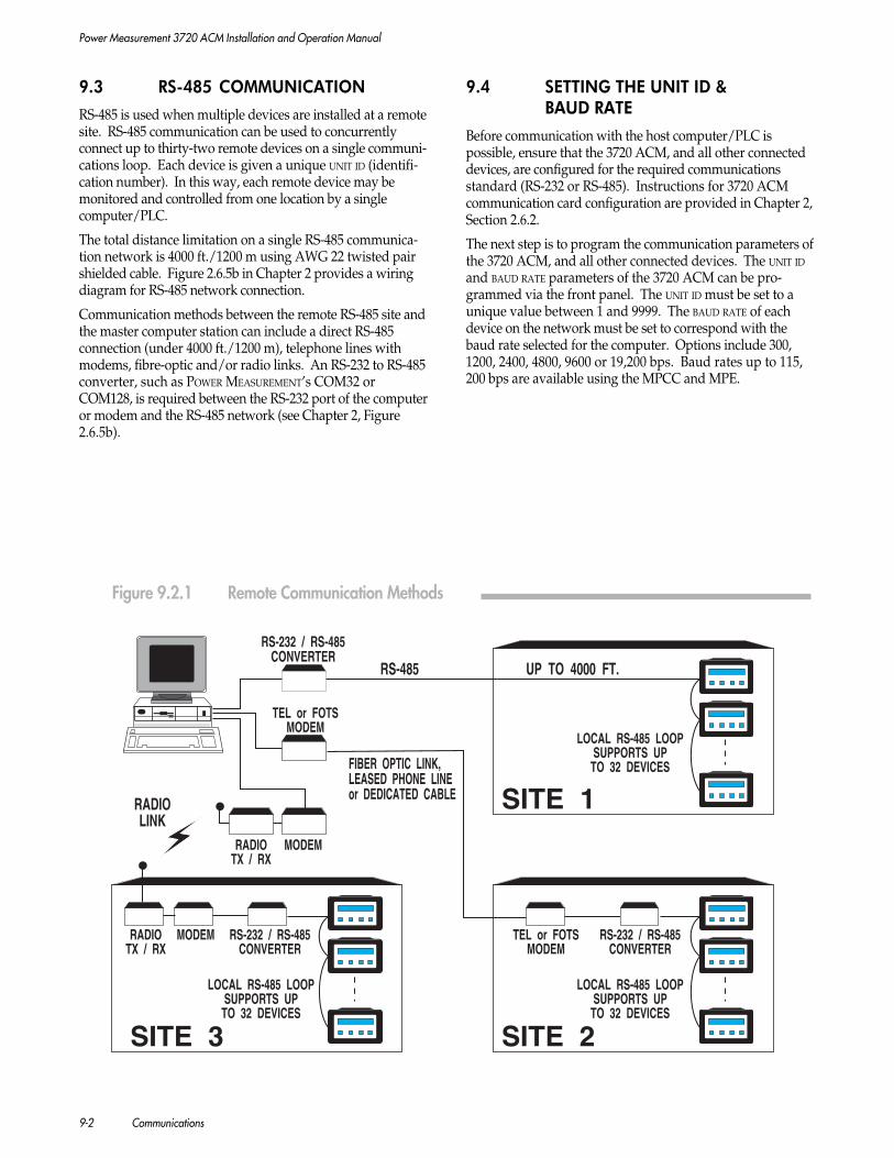
Power Measurement 3720 ACM Installation and Operation Manual
9-2 Communications
RS-232 / RS-485CONVERTER
RS-485
RADIOLINK
FIBER OPTIC LINK,LEASED PHONE LINEor DEDICATED CABLE SITE 1
SITE 2SITE 3
RS-232 / RS-485CONVERTER
RS-232 / RS-485CONVERTER
LOCAL RS-485 LOOPSUPPORTS UP
TO 32 DEVICES
LOCAL RS-485 LOOPSUPPORTS UP
TO 32 DEVICES
LOCAL RS-485 LOOPSUPPORTS UP
TO 32 DEVICES
TEL or FOTSMODEM
TEL or FOTSMODEM
RADIOTX / RX
MODEM
MODEMRADIOTX / RX
UP TO 4000 FT.
9.3 RS-485 COMMUNICATION
RS-485 is used when multiple devices are installed at a remotesite. RS-485 communication can be used to concurrentlyconnect up to thirty-two remote devices on a single communi-cations loop. Each device is given a unique UNIT ID (identifi-cation number). In this way, each remote device may bemonitored and controlled from one location by a singlecomputer/PLC.
The total distance limitation on a single RS-485 communica-tion network is 4000 ft./1200 m using AWG 22 twisted pairshielded cable. Figure 2.6.5b in Chapter 2 provides a wiringdiagram for RS-485 network connection.
Communication methods between the remote RS-485 site andthe master computer station can include a direct RS-485connection (under 4000 ft./1200 m), telephone lines withmodems, fibre-optic and/or radio links. An RS-232 to RS-485converter, such as POWER MEASUREMENT’s COM32 orCOM128, is required between the RS-232 port of the computeror modem and the RS-485 network (see Chapter 2, Figure2.6.5b).
9.4 SETTING THE UNIT ID &BAUD RATE
Before communication with the host computer/PLC ispossible, ensure that the 3720 ACM, and all other connecteddevices, are configured for the required communicationsstandard (RS-232 or RS-485). Instructions for 3720 ACMcommunication card configuration are provided in Chapter 2,Section 2.6.2.
The next step is to program the communication parameters ofthe 3720 ACM, and all other connected devices. The UNIT IDand BAUD RATE parameters of the 3720 ACM can be pro-grammed via the front panel. The UNIT ID must be set to aunique value between 1 and 9999. The BAUD RATE of eachdevice on the network must be set to correspond with thebaud rate selected for the computer. Options include 300,1200, 2400, 4800, 9600 or 19,200 bps. Baud rates up to 115,200 bps are available using the MPCC and MPE.
Figure 9.2.1 Remote Communication Methods

Power Measurement 3720 ACM Installation and Operation Manual
Communications 9-3
CAUTION
When using a modem interface betweenthe host computer and any remotedevice(s), ensure that the host computer isnot used to set the BAUD RATE parameter ofany selected device outside the workingrange of the modem. Doing so will causethat meter to cease communicating. Re-establishing communication with thatmeter is then only possible through per-forming the following:
1. Reset the baud rate of the remote de-vice from its front panel to a value withinthe working range of the modem.
2. Set the computer to communicate atthe baud rate at which the remote de-vice has been set to communicate.
9.5 3720 ACM TRAN MODEL OPERATION
The TRAN version of the 3720 ACM provides all the func-tions of the 3720 ACM, except that it has no front paneldisplay or keypad. All measured parameters, status informa-tion, and programming parameters are accessed via commu-nications.
To initiate communications with the device, the factory-setUNIT ID and BAUD RATE must be used:
UNIT IDThis is set at the factory to be the last 4 digits of theunit’s serial number, which can be found on the rearcover of the unit. For example, a unit with serial number71317 will be preset to UNIT ID of 1317.
BAUD RATEThis is set at the factory to 9600 baud.
Once communication has been established using the factorydefaults, the device’s operating parameters may be changedusing the remote computer. You may also reset the UNIT ID ofthe device to any other desired value, as well as resetting theBAUD RATE. Refer to Section 9.4 for important informationregarding resetting the BAUD RATE.
9.6 POWER MEASUREMENT'S SCADA SYSTEM
The 3720 ACM maintains compatibility with POWER
MEASUREMENT’s PC-based power monitoring softwarepackages, M-SCADA, L-SCADA, PowerView, and entirefamily of 3000 series digital instrumentation, which includespower meters, power demand controllers, and smart trans-ducer interfaces. A single M-SCADA station can support upto 99 remote sites with a total of 3168 devices. L-SCADAsupports 12 sites with a total of 12 devices. Systems are easilyexpandable.
The SCADA software provides extensive full-color datadisplay options, automated data handling and system controlfeatures including:
• Real-time data display for all or part of the powersystem. Full color, user-configurable system diagrams canbe used to give a system-wide display of powerconditions. Real-time and logged data for individualdevices can also be viewed.
• Display of captured waveforms and harmonic analy-sis. The 3720 ACM provides on-board harmonicanalysis to the 15th harmonic. The SCADA softwarecan provide more detailed power quality analysis tothe 63rd harmonic in graphical or tabular formats.
• Display of 12-cycle waveform recorder data. Wave-forms for all inputs can be displayed concurrently onthe screen for fault or surge/sag analysis.
• Historical trend graphing. The SCADA software candisplay historical, time-interval triggered Snapshot Logdata in graphical format.
• Detection, annunciation, display and logging of alarmconditions.
• Automatic retrieval and disk archival of data logs fromremote devices.
• Manual control of the on-board relays of all POWER
MEASUREMENT devices.
• Remote programming of the setup parameters of allPOWER MEASUREMENT devices.
POWER MEASUREMENT’s proven distributed processing approach topower monitoring guarantees consistently accurate dataretrieval by delegating extensive data acquisition, datalogging, and control capabilities to the remote meter/RTUsites. Less processing requirements at the master stationmeans high reliability and performance. Non-volatile datalogs ensure data is always retrievable following a temporarypower or communication failure.
Contact POWER MEASUREMENT or your local POWER MEASURE-MENT representative for detailed information on the SCADAsystem and the complete range of POWER MEASUREMENT
instrumentation and PC-based software products.
9.7 THIRD-PARTY SYSTEM COMPATIBILITY
3720 ACM communications uses an advanced object andregister based open protocol which supports an efficientexception reporting methodology. This allows the 3720 ACMto be easily adapted to third-party PLC, DCS, EMS, andSCADA systems.
All data and configuration registers are accessible via commu-nications. All configuration and control operations haveembedded password protection.
Contact POWER MEASUREMENT or your local POWER MEASURE-MENT representative for complete documentation on the 3720ACM communications protocol, or to discuss a specificapplication.

Power Measurement 3720 ACM Installation and Operation Manual
9-4 Communications
the Bridge/Mux. A custom cable is required between theBM85 and the 3720 ACM (see Figure 9.8.1).
Multi-DropA multi-drop topology allows up to thirty-two 3720 ACMs to beconnected to each of the four BM85 Bridge/Mux ports. TheRS-485 port of each 3720 ACM is connected on an RS-485network that is interfaced to the Modbus via an RS-232 to RS-485 converter, such as POWER MEASUREMENT's COM32TM orCOM128TM. This allows for up to 128 power meters to beconnected to each BM85 (see Figure 9.8.1). The cable connect-ing the Bridge/Mux to the converter is a 9-pin male to 25-pinmale serial cable. Refer to Section 2.6.5 for RS-485 networkconnections.
9.8.2 SETTING COMMUNICATIONS PARAMETERS
When using Modbus communications, the range of possibleUNIT ID designations for the 3720 ACM must be between 1and 247.
The COM MODE parameter should be set according to thecommunications topology being used (RS-232 for single, RS-485 for multi-drop).
The Modbus protocol setup provides two additional param-eters:
• REGISTER SIZE
This determines whether a 16-bit (16B) or an extended32-bit (32B) register is passed in communications foreach function. The default setting is 16B.
• INVALID OBJECTS
This specifies whether or not the 3720 ACM returns avalue for an invalid object. The options are YES or NO.If YES is selected, the 3720 ACM will return a value ofeither 0 or 0xFFFF for an invalid object.
9.8.3 COMMUNICATIONS PROTOCOL
Communications occurs from the Controller via the ModbusPlus network (using MSTR block), across the BM85 to theModbus, and on to the 3720 ACM(s) via the RS-232 / RS-485converter (multi-drop only).
All communications between the BM85 and 3720 ACM(s)conform to a master/slave scheme with the BM85 as the masterand the 3720 ACM(s) as slave(s).
Message Packets SupportedAll registers within the 3720 ACM are accessible as PLC 4xxxxholding registers. The following Modbus commands aresupported:
PRESET MULTIPLE REGISTERS (10H)allows the Modicon Controller to define all the user-program-mable setup parameters in the 3720 ACM. Registers are alsoprovided to allow the Controller to clear the energy consump-tion (kWh, kVAh, kVARh) and status input counters of the3720 ACM .
9.8 MODBUS PROTOCOL
The 3720 ACM provides compatibility with the ModiconMODBUS system. The Modbus communications protocolallows information and data to be efficiently transferredbetween a Modicon Programmable Controller and a 3720ACM. The 3720 ACM performs Modbus communications byemulating a Modicon 984 Controller.
All 3720 ACM measured data can be accessed, including allreal-time and demand values (kW, Amps or kVA). Polarity ofpower measurements can be determined through polarityregisters.
All values from all Preset Minimum/Maximum Logs and allentries in the Event Log are also accessible, including indi-vidual time stamps. The contents of the Snapshot Logs orWave Recorder Logs are not available.
The condition of each of the four status inputs and threerelays can be read. The relays may also be controlled manu-ally via communications.
The protocol also provides commands to initiate waveformcapture and to read the sampled waveform data.
All setup parameters can be read and/or configured, includ-ing setpoint and relay setup. Optional password protection isalso provided.
The Modbus protocol supports standard 16 bit, as well as 32bit extended registers. 32 bit registers would typically berequired only for large energy values (i.e. KWH, etc.).
NOTE
The Modbus protocol is not compatiblewith POWER MEASUREMENT’s SCADA soft-ware.
Modbus RTU protocol is used over Ethernet on the optionalMPE communications card.
9.8.1 HARDWARE REQUIREMENTS ANDWIRING
A Modicon BM85 Bridge/Multiplexer is required between theModbus and Modicon Controller. An RS-232 to RS-485converter may also be required. This is described below.
Single DropA single drop topology allows one 3720 ACM to be interfaceddirectly to the Modbus via its RS-232 port. Up to four 3720ACMs may be connected to each BM85, one to each port of
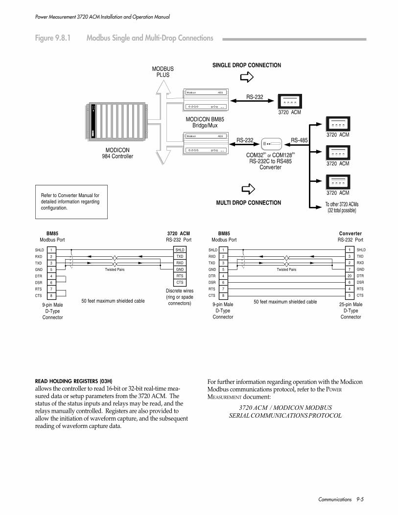
Power Measurement 3720 ACM Installation and Operation Manual
Communications 9-5
SHLD 1
RXD 2
TXD 3
GND 5
DTR 4
DSR 6
RTS 7
CTS 8
3720 ACMRS-232 Port
BM85Modbus Port
Twisted Pairs
SHLD
TXD
RXD
GND
RTS
CTS
50 feet maximum shielded cable9-pin Male
D-TypeConnector
Discrete wires(ring or spadeconnectors)
ConverterRS-232 Port
BM85Modbus Port
Twisted Pairs
50 feet maximum shielded cable9-pin MaleD-Type
Connector
25-pin MaleD-Type
Connector
SHLD 1
RXD 2
TXD 3
GND 5
DTR 4
DSR 6
RTS 7
CTS 8
1 SHLD
3 TXD
2 RXD
7 GND
20 DTR
6 DSR
4 RTS
5 CTS
Refer to Converter Manual fordetailed information regardingconfiguration.
Figure 9.8.1 Modbus Single and Multi-Drop Connections
READ HOLDING REGISTERS (03H)allows the controller to read 16-bit or 32-bit real-time mea-sured data or setup parameters from the 3720 ACM. Thestatus of the status inputs and relays may be read, and therelays manually controlled. Registers are also provided toallow the initiation of waveform capture, and the subsequentreading of waveform capture data.
For further information regarding operation with the ModiconModbus communications protocol, refer to the POWER
MEASUREMENT document:
3720 ACM / MODICON MODBUSSERIAL COMMUNICATIONS PROTOCOL

Power Measurement 3720 ACM Installation and Operation Manual
9-6 Communications
9.9 ALLEN BRADLEY DF-1 PROTOCOL
The Allen Bradley DF-1 protocol for the 3720 ACM-MPCC/MPE provides compatibility with Allen Bradley PLC devicesand access to the Allen-Bradley Data Highway Plus (and DataHighway). See Figure 9.9.1. The Allen Bradley (AB) FullDuplex DF-1 protocol allows information to be transferredeasily between an AB Programmable Logic Control (PLC) anda 3720 ACM-MPCC/MPE. The 3720 ACM performs thecommunications by emulating an AB PLC-5. The 3720 ACM-MPCC/MPE implements two commands from the PLC-5command set: Typed Read and Typed Write. The AB DF-1protocol allows data to efficiently transferred between an ABPLC and a 3720 ACM-MPCC/MPE.
All 3720 measured data can be accessed, including all real-time and demand values. All values from the Preset Min/Max Logs, with their respected timestamps, are also available.Contents of the Snapshot Logs and Event Log are notavailable. The condition of all four status inputs and threerelays can be read. The relays can also be controlled manuallythrough communications. The AB DF-1 protocol alsoprovides commands to initiate a waveform capture of a singlechannel and a waveform recorder of all eight channels. Thesampled waveform data can then be downloaded for analysis.All setup parameters can be read and/or configured includingthe relay setup. The Snapshot Log and Setpoint Setup cannotcurrently be configured. The AB DF-1 protocol supportsstandard 16-bit, as well as 32 bit extended registers. The 32-bit registers are typically only required to read large real-timevalues and possibly in configuring certain registers.
9.9.1 HARDWARE REQUIREMENTS ANDWIRING
The 3720 ACM-MPCC/MPE interfaces to the Data Highwayvia two Allen-Bradley Communication Interface Modules -the 1770-KF2 Series B Communication Interface Module and the 1785-KE Series B Data Highway Plus RS-232-C Communications Module.
Single DropA single drop communications topology allows one 3720 ACM-MPCC/MPE to be connected to the data highway via an ABcommunication interface module using RS-232 communica-tions. A direct RS-232 connection is made between the ABinterface module and the 3720 ACM-MPCC/MPE (See Figure9.9.1).
Multi-DropA multi-drop communications topology allows you to connectup to 32 - 3720 ACM-MPCC/MPEs to the data highway viaone AB communications interface module using RS-485communications. A POWER MEASUREMENT COM32 orCOM128 RS-232 to RS-485 Converter is required for multi-drop systems (See Figure 9.9.1).
9.9.2 COMMUNICATIONS PROTOCOL
All communications between the PLC and the 3720 ACM-MPCC/MPE(s) conform to a master/slave scheme. Informationis transferred between a master PLC and slave 3720 ACM-MPCC/MPE(s). Communications occur from the PLC (usinga MSG block) to the 3720 ACM-MPCC/MPE(s) via the RS-232/RS-485 converter (multi-drop only).
Communication ParametersWhen using the AB DF-1 protocol, the range of possible UNIT
ID designations for the 3720 ACM must be between 1 and 99.
The Allen-Bradley protocol setup provides an additionalparameter - Register Size. This determines whether a 16-bit oran extended 32-bit register is passed in communications foreach request. The default setting is 16-bit.
Message Packets SupportedThe following message packets are supported:
PLC-5 TYPED READ (READ BLOCK)allows the PLC to read 16-bit or 32-bit real-time measureddata or setup parameters from the 3720 ACM-MPCC/MPE.The status of the status inputs or relays may be read. Thedownloading of the Waveform Capture Log and the Wave-form Recorder Log are supported.
PLC-5 TYPED WRITE (WRITE BLOCK)allows the AB PLC to define all the user-programmable setupparameters in the 3720 ACM-MPCC/MPE with the exceptionof the setpoint and snapshot log configuration. Registers arealso provided to allow the PLC to control the relays and clearthe Preset Minimum/Maximum Logs, energy consumptionregisters and the status input counters of the 3720 ACM.
For more information regarding operation with AB communi-cations protocol, refer to the POWER MEASUREMENT document:
3720 ACM-MPCC ALLEN-BRADLEY DF-1SERIAL COMMUNICATIONS PROTOCOL

Power Measurement 3720 ACM Installation and Operation Manual
Communications 9-7
SHLD 1
TXD 2
RXD 3
RTS 4
CTS 5
DSR 6
GND 7
DCD 8
DTR 11
GND 13
1770-KERS-232 Port
SHLD
RXD
TXD
SG
3720 ACMRS-232 Port
1785-KERS-232 Port
ConverterRS-232 Port
50 feet maximum
1770-KF2Asynchronous Port
(RS-232)SHLD 1
TXD 2
RXD 3
RTS 4
CTS 5
DSR 6
GND 7
DCD 8
DTR 20
SHLD
RXD
TXD
SG
3720 ACMRS-232 Port
25-pinMale
Connector
50 feet maximum
15-pinMale
Connector
SHLD 1
TXD 2
RXD 3
RTS 4
CTS 5
DSR 6
GND 7
DCD 8
DTR 11
GND 13
1 SHLD
2 RXD
3 TXD
4 RTS
5 CTS
6 DSR
7 GND
8 DCD
20 DTR
25-pinMale
Connector
50 feet maximum
15-pinMale
Connector
1770-KF2Asynchronous Port
(RS-232)SHLD 1
TXD 2
RXD 3
RTS 4
CTS 5
DSR 6
GND 7
DCD 8
DTR 11
1 SHLD
2 RXD
3 TXD
4 RTS
5 CTS
6 DSR
7 GND
8 DCD
20 DTR
ConverterRS-232 Port
50 feet maximum
25-pinMale
Connector
25-pinMale
Connector
Refer to Converter Manual fordetailed information regardingconfiguration.
Figure 9.9.1 Allen Bradley Single and Multi-Drop Connections

Power Measurement 3720 ACM Installation and Operation Manual
9-8 Communications
9.10 ALARM DIALER PROTOCOL
The 3720 ACM-MPCC/MPE Alarm Dialer is used to initiatecommunications and send alarms from remote sites inresponse to preconfigured alarm conditions. The AlarmDialer can be used to contact PEGASYS stations or sendinformation to remote terminals and printers. This allows theannuciation of alarms occurring at remote sites that are notequipped with PEGASYS.
9.10.1 HARDWARE REQUIREMENTS ANDWIRING
The Alarm Dialer protocol can be configured to run on any orall of the ports on the 3720 ACM-MPCC/MPE.
Only one MPCC/MPE Alarm Dialer can be used on anetwork of devices. Other devices can monitor alarm condi-tions and communicate to the Alarm Dialer, provided theseother devices have the ability to output a digital signal. Inthis application, the devices monitoring the alarm conditionssend pulses to the 3720 ACM-MPCC/MPE Alarm Dialer,which in turn initiates communication and dials out thealarm. In order to transmit pulses between devices, controlwiring must be installed, and the 3720ACM with the AlarmDialer must be properly configured. If you require dial-out ofalarms that originate on other devices in the network, contactPOWER MEASUREMENT Customer Service for assistance config-uring your system.
NOTE
When alarm conditions occur, the AlarmDialer listens for communications traffic onthe network. If other communications arein progress, the Alarm Dialer deactivatesand waits for the other communications tocomplete. Only alarms that are processedwhen the network is quiet will dial-outsuccessfully.
RS-232 ConnectionA direct connection can be made between the 3720ACM-MPCC/MPE's RS-232 port and the modem.
RS-485 ConnectionEither of the MPCC/MPE's RS-485 ports can be used with theAlarm Dialer. The RS-485 bus that the Alarm Dialer isconfigured on must be connected to the modem (an RS-232 toRS-485 converter, such as POWER MEASUREMENT’S COM128, isrequired).
9.10.2 CONFIGURATION
The Alarm Dialer is configured using PowerView for Win-dows, available from POWER MEASUREMENT.
A total of 10 phone numbers can be configured for the AlarmDialer (10 numbers total for all ports combined). Phonenumbers cannot be shared between MPCC/MPE ports.
Configuration of the MPCC/MPE ports requires directconnection: you must configure the Alarm Dialer parameterswhile connected to the port you want to use for dial-out. Ifyou intend to use multiple ports, connect to each port toconfigure its Alarm Dialer parameters.
Refer to the on-line help available in PowerView for Windowsfor configuration information.
Alarm ConditionsEach phone number can have up to 12 different alarmconditions trigger a dial-out. Valid alarm conditions includestatus inputs, high-speed setpoints or normal setpoints goingactive, inactive, or changing state. Each alarm condition alsohas a priority associated with it. When the phone number iscalled, the highest priority alarm currently active for thatnumber will be sent to the remote system. Multiple stationscan be called for a single alarm.
Modem SupportThe Alarm Dialer does not directly support any particularmodem. To allow compatibility with a wide variety ofmodems, the modem initialization string and dialer string foreach phone number is fully configurable using Wmodem, autility available from POWER MEASUREMENT.
For more information regarding the AD protocol, refer to thePOWER MEASUREMENT document:
3720 ACMSERIAL COMMUNICATIONS PROTOCOL

Mechanical Dimensions A-1
Power Measurement 3720 ACM Installation and Operation Manual
APPENDIX A
MECHANICAL & MOUNTING DIMENSIONS
BASIC MODEL
12.60"(320 mm)
7.70"(196 mm)
FRONT PANEL
0.35"(9 mm)
RIGHT SIDE
TerminalStrips
Comm. CardTerminal Strip
4 mountingstuds #8-32
½" long(12 mm)
4.60"(117 mm)
Behind Panel Depth
PlasticBezel
11.20"(284 mm)
6.90"(175 mm)
5.30"(135 mm)
11.90"(302 mm)
PANEL CUTOUT
4 mounting holes3/16" (4.8 mm) diameter
0.80"(20 mm)

Power Measurement 3720 ACM Installation and Operation Manual
A-2 Mechanical Dimensions
6.50"(165 mm)
11.10"(282 mm)
11.90"(302 mm)
12.40"(315 mm)
4 mounting holes0.25" (6.4 mm) diameter
Edge of chassisbehind faceplate
FRONT FACEPLATE
5.30"(135 mm)
MECHANICAL & MOUNTING DIMENSIONS
TRAN MODEL
RIGHT SIDE
FrontFaceplate
TerminalStrips
Comm. CardTerminal Strip
4.68"(119 mm)
Behind Panel Depth(unit mounted face-to-panel)
0.60"(15 mm)

Mechanical Dimensions A-3
Power Measurement 3720 ACM Installation and Operation Manual
MECHANICAL & MOUNTING DIMENSIONS
REAR PANEL
VAUXI11
I12I21
I22I31
I32I42
S1
S2
S3
S4
SCOM
I41
Edge of
Front B
ezel
VAUXIOUT
AUXILIARY
AUXILIARY
CURRENT INPUTSSTATUS INPUTS
I11I12
I21I22
I31I32
I42S
1S
2S
3S
4SCOM
I41
R11
R13
R21
R22
R12
R23
R31
R33
V1
V2
V3
VREFN/-
L/+R
32
VOLTAGE INPUTSPOW
ER
NOTE
Rear panel of basic model isshown. For TRAN model, dis-regard edge of front bezel.

Power Measurement 3720 ACM Installation and Operation Manual
A-4 Mechanical Dimensions

Power Measurement 3720 ACM Installation and Operation Manual
Setpoint Parameter Form B-1
APPENDIX B
SETPOINT PARAMETER FORM
Standard Setpoints
SETPOINT TRIGGER PARAMETER HIGH LIMIT LOW LIMIT TD OPERATE TD RELEASE ACTION1 ACTION2
H01
H02
H03
H04
H05
H06
High Speed Setpoints
SETPOINT TRIGGER PARAMETER HIGH LIMIT LOW LIMIT TD OPERATE TD RELEASE ACTION1 ACTION2
S01
S02
S03
S04
S05
S06
S07
S08
S09
S10
S11

Power Measurement 3720 ACM Installation and Operation Manual
B-2 Setpoint Parameter Form

Power Measurement 3720 ACM Installation and Operation Manual
Firmware Versions C-1
APPENDIX C
FIRMWARE VERSIONS
The following table lists each firmware version release for the3720 ACM and the new features or performance enhance-ments added with each release.
The version number can be viewed from the front panel inProgramming Mode. If your 3720 ACM is currently using afirmware version older than the most recent version listed inthe table below, you may upgrade the firmware in that unit bycontacting your local representative or the manufacturer.
VERSION RELEASE DATE DESCRIPTION
V 1.1.1.X July 1993 Initial release.
V1.2.X.X January 1994 Adds K-Factor and predictive demand measurements.Adds TOU registers.Expanded waveform recorder, selectable 3 x 12-cycle,2 x 18-cycle, or 1 x 36-cycle storage.Adds setpoint-triggered waveform capture.Adds meter-to-meter time sync capability.Adds high-speed snapshot log.Status input counters now scalable.Additional setpoint actions and high-speed parameters.
V1.3.X.X August 1994 Adds independent thermal demand period (THERMAL PERIOD).Adds independent demand synchronization parameter (DEMAND SYN).Thermal constant redefined as the time required to reach 90% of registration.Adds automatic daylight savings time support.Adds high-speed frequency measurements.Modicon Modbus protocol supported.
V 1.4.X.X August 1995 Support for V 0.0.0.5 of the MPCC.
V 1.5.X.X March 1996 Support for V 1.X.X.X of the MPCC and V2.X.X.X of the MPE.Waveform recorder support through Modbus protocol.Adds secondary volt/amp measurements.
Either contact will need to know the serial number of the 3720ACM and the firmware version number indicated on the rearcover label.
Most upgrades to the 3720 ACM require a simple replacementof the EPROM (integrated circuit "chip") inside the unit whichcontains the operating firmware. Complete instructions forthis procedure are provided with the replacement EPROM.

Power Measurement 3720 ACM Installation and Operation Manual
C-2 Firmware Versions

Power Measurement 3720 ACM Installation and Operation Manual
Technical Specifications D-1
APPENDIX D
TECHNICAL SPECIFICATIONS
PARAMETER ACCURACY3 (% of full scale) FRONT PANEL DISPLAYBasic XAMPS Resolution Range
Current 0.2 % 0.3 % 0.1 % 0 - 30,000Current Unbalance 1.0 % 1.0 % 1.0 % 0 - 100 %
kW 0.4 % 0.5 % 0.1 % 0 - 999,9992
kVAR 0.4 % 0.5 % 0.1 % 0 - 999,9992
kVA 0.4 % 0.5 % 0.1 % 0 - 999,9992
kWh 0.4 % 0.5 % 1 KWH 0 - 999,999,999kVARh 0.4 % 0.5 % 1 KVARH 0 - 999,999,999kVAh 0.4 % 0.5 % 1 KVAH 0 - 999,999,999
Voltage 0.2 % 0.1 % 0 - 999,9991
Voltage Unbalance 1.0 % 1.0 % 0 - 100 %
Power Factor 1.0 % 1.0 % -0.6 to 1.0 to +0.6Frequency 0.05 Hz 0.01 Hz 20.00 to 75.00 Hz
Harmonic Distortion 1.0 % 0.1 % 0.0 to 1000.0 %K-Factor 10.0 % 0.1 1.0 to 9999.9
I4 0.1% 0 - 9,999Vaux 0.25 % 0.1 % 0 - 999,999
CURRENT OVERRANGE OPTIONSOption Accuracy Current Input Overrange
Amps Power % Full Scale AmpsBasic
Basic 0.2 % 0.4 % 125% 6.25XAMPS 0.3 % 0.5 % 200% 10.00
1. Reads in kV for voltages over 9,9992. Reads in MVA, MW, MVAR for readings over 9,999k3. @50.0 Hz or @60.0 Hz @ 25°C (77°F)
WAVEFORM CAPTURE & RECORDING
Waveform CaptureSampling Rate: approximately 128 times per cycleSampling Accuracy: 2% of full scaleResolution: 10 bits (0.1 %)
Waveform RecordingSampling Rate: approximately 16 times per cycleSampling Accuracy: 2% of full scaleResolution: 10 bits (0.1 %)
0.2% 0.3% 0.8% 2.0%

Power Measurement 3720 ACM Installation and Operation Manual
D-2 Technical Specifications
INPUT & OUTPUT RATINGS
APPENDIX D TECHNICAL SPECIFICATIONS
Voltage Inputs: Basic Model: 120 VAC nominal full scale input.
277 Option: 277 VAC nominal full scale input.
347 Option: 347 VAC nominal full scale input.
Overload withstand for all options: 1500 VAC continuous, 2500 VAC for 1 second.Input impedance for all options: 2 Megohm
Current Inputs: Basic Model: 5.000 Amps AC nominal full scale input.
Overload withstand for all options: 15 Amps continuous, 300 Amps for 1 sec.Input impedance: 0.002 ohm, Burden: 0.05 VA
Aux. Voltage Input: 1.0 VAC/VDC nominal full scale input (1.25 VAC /VDC max.)Overload withstand: 120 VAC/VDC continuous, 1000 VAC/VDC for 1 second.Input impedance: 10 Kohm
Control Relays: Basic Model: Form C dry contact. 277 VAC / 30 VDC@ 10 Amp resistive
SSR Option: SPST solid state. 24 to 280 VAC (use AC only)@ 1 Amp resistive
Aux. Current Output: 0 to 20 mA into max. 250 ohm load. Accuracy: 2%
Status Inputs: +30 VDC differential SCOM output to S1, S2, S3, or S4 input.Min. Pulse Width: 40 msec.
Power Supply: Basic Model: 100 to 240 VAC ± 10% / 47 to 440 Hz110 to 300 VDC ± 10%
P24/48 Option: 20 to 60 VDC @ 15W
Includes a 250V, 2A time-lag Type T fuse on the L/+ terminal.
Operating Temperature: Basic Model: 0oC to 50oC (32oF to 122oF) ambient air.
XTEMP Option: -20oC to +70oC (-4oF to +158oF)
Storage Temperature: -30oC to +70oC (-22oF to +158oF)
Humidity: 5 to 95 %, non-condensing
Altitude: The maximum operating altitude is 2000 m (6100 ft.)
Shipping: Weight: 3.9 kg (8lbs. 10 oz.) Carton: 38 x 25 x 18 cm (15" x 9.8" x 7.1").
Voltage, Current, Status, Relay and Power inputs all pass the
ANSI/IEEE C37.90A-1989 surge withstand and fast transient tests.
LR 57329UL 3111-1NRTL/C
LISTEDINDUSTRIAL CONTROL EQUIPMENT1T98

Power Measurement 3720 ACM Installation and Operation Manual
Model/Ordering Information E-1
APPENDIX E
MODEL/ORDERING INFORMATION
BASIC MODELS
3720ACM includes front panel display / keypad
3720ACM TRAN without display / keypad
OPTIONS (SPECIFY WHEN ORDERING)
277 To monitor 277/480 Volts (instead of 120 Volts)
347 To monitor 347/600 Volts (instead of 120 Volts)
XAMPS 200% overrange capability on Amps inputs
SSR SPST solid state relays (instead of Form C dry contact electromechanical)
P24/48 20 to 60 VDC powered (instead of 85 to 264 VAC or 110 to 300 VDC)
TROP Tropicalization (conformal coating) treatment
RACK 19 inch rack mountable chassis
MPCC Multiport communications card
MPE Multiport communications card with Ethernet
ORDERING EXAMPLE
3720ACM -277 -XAMPS -SSR

Power Measurement 3720 ACM Installation and Operation Manual
E-2 Model/Ordering Information

Power Measurement 3720 ACM Installation and Operation Manual
Warranty And Registration F-1
APPENDIX F
WARRANTY AND REGISTRATION
WARRANTY
This product is warranted against defects in materials andworkmanship for three years. The Warranty is effective fromdate of purchase. POWER MEASUREMENT LIMITED will repair orreplace, at its option, any product found to be defective(F.O.B. point of manufacture) during the Warranty period,provided the equipment has been installed, wired, pro-grammed, and operated in accordance with themanufacturer’s instruction manual included with each unit,and the applicable sections of the Electrical Code.
The Warranty will be invalid if any unauthorized alterationsare made to the product, or if the product has been abused ormishandled. Damage due to static discharges will void theWarranty, as will application of voltages or currents outsidethe specified ratings of the device inputs.
EXCEPT TO THE EXTENT PROHIBITED BY APPLICABLELAW, NO OTHER WARRANTIES, WHETHER EXPRESSEDOR IMPLIED, INCLUDING WARRANTIES OF MERCHANT-ABILITY AND FITNESS FOR A PARTICULAR PURPOSE,SHALL APPLY TO THIS PRODUCT; UNDER NO CIRCUM-STANCES SHALL POWER MEASUREMENT LIMITED BELIABLE FOR CONSEQUENTIAL DAMAGES SUSTAINEDIN CONNECTION WITH SAID PRODUCT AND POWERMEASUREMENT LIMITED NEITHER ASSUMES NORAUTHORIZES ANY REPRESENTATIVE OR OTHER PERSONTO ASSUME FOR IT ANY OBLIGATION OR LIABILITYOTHER THAN SUCH AS IS EXPRESSLY SET FORTHHEREIN.
PRODUCT RETURN PROCEDURE
The following procedure must be strictly adhered to whenreturning any POWER MEASUREMENT product to the factory forthe purpose of repair, replacement, credit, upgrade,recalibration, or for any other reason.
1. Contact POWER MEASUREMENT or your local POWER
MEASUREMENT Sales Representative and obtain a ReturnMerchandise Authorization (RMA) number prior to shipmentof any unit back to the manufacturer. Be prepared toprovide the product’s model number, serial number, andthe reason for returning the unit. Units received withoutprior authorization will not be accepted under anycircumstances.
2. If the unit is being returned for repair, replacement, orupgrade a product return report should be completed andincluded with the unit. The information providedshould include:
A functional description of the unit defect or failureand the electrical/environmental conditions at thetime of failure. This will significantly reduce repair/upgrade time (and cost, if warranty has expired). Ifthe unit is being returned for an upgrade, recalibrationor other modification, list the requirements.
The RMAnumber issued by POWER MEASUREMENT, theserial number of the unit, the company name andaddress, the name of the person filling out the report,and the date.
IMPORTANT: The return address to which the unitis to be shipped following servicing.
3. Pack the unit safely, preferrably in the original shippingcarton, and include the detailed report described above.The RMA number must be clearly marked on the outsideof the box.
4. A packing slip must be attached to the outside of the boxwhich includes the points of origin and destination, adescription of contents, and the reason for return.Examples: For Repair and Return, or Returned for Credit. Thereshould be no need to declare a value.
5. Ship PREPAID to the appropriate address below. POWER
MEASUREMENT will not accept C.O.D. shipments. If theunit is still under warranty, POWER MEASUREMENT willpay the return shipping charges.
For shipments originating in the U.S.A.:
Power Measurementc/o VICTORIA CUSTOMS BROKERS4131A Mitchell WayBellingham, WA 98226
For shipments originating overseas:
Power Measurement2195 Keating Cross RoadSaanichton, BC V8M 2A5
CUSTOMS CLEARANCELivingston International Inc.Telephone: (250) 388-4435
For shipments originating in Canada:
Power Measurement2195 Keating Cross RoadSaanichton, BC V8M 2A5
REGISTRATION
Please complete and mail the enclosed Warranty Registration cardimmediately. This will allow us to add you to our mailing list,to keep you up to date on the latest product firmware releasesand new feature offerings.
Your comments and suggestions for product improvementand feature additions are welcome.

Power Measurement 3720 ACM Installation and Operation Manual
F-2 Warranty And Registration

Power Measurement 3720 ACM Installation and Operation Manual
Troubleshooting G-1
APPENDIX G
TROUBLESHOOTING
A number of problems can cause the 3720 ACM not tofunction properly. This chapter lists a number of symptoms,and explains how to correct them.
1. If the display does not operate:
a) check that there is at least 110 volts available to thepower supply (L and N connections on the terminalstrip).
b) confirm that the Chassis Ground Lug terminal isconnected directly to ground.
c) turn the power off for 10 seconds.
If the above steps do not solve the problem, perform thefollowing:
a) As a diagnostic test, turn the unit off (disconnectpower) for at least ten seconds. Apply power againand check if the unit powers up correctly.
b) Contact POWER MEASUREMENT or your local POWER
MEASUREMENT representative and report the problemand results of the test.
2. If the voltage or current readings are incorrect:
a) check that the voltage mode is properly set for thegiven wiring.
b) check that the voltage and current scales areproperly set.
c) make sure the Chassis Ground Lug terminal isproperly grounded.
d) check the quality of the CT’s and PT’s being used.
e) make the following voltage tests:
i) V1, V2, V3 to VREF should be 120 VAC (for thestandard voltage input option). This dependson the voltage input option installed (i.e. -277, -347).
ii) Chassis Ground Lug to switchgear earthground should be 0 V.
3. If the kW or Power Factor readings are incorrect butvoltage and current readings are correct:
Make sure that the phase relationship betweenvoltage and current inputs is correct by comparingthe wiring with the appropriate wiring diagram. Note thatPOWER MEASUREMENT’s M-SCADA PC-basedsoftware can be used to verify PT and CT sequenceand polarity by analyzing the captured voltage andcurrent waveforms for each phase.
4. If RS-232C or RS-485 communication does not work:
a) check that the baud rate of the host computer/PLCis the same as that of the 3720 ACM.
b) check that the communications mode (RS-232 or RS-485) set by the jumper on the communications cardis correct for the type of standard being used (seeChapter 2, Section 2.6.2).
c) check all communications wiring (see Chapter 2,Figures 2.6.4 to 2.6.6).
d) check that the number of data bits is set to 8, withone stop bit and no parity.
If the above steps do not solve the problem, perform thefollowing:
a) As a diagnostic test, turn both the 3720 ACM off(disconnect power) and the computer off for at leastten seconds. Apply power again and check if thecommunications operate successfully.
b) Contact POWER MEASUREMENT or your local POWER
MEASUREMENT representative and report the problemand results of the test.
If the symptom persists after performing the specified steps,or if the symptom is not listed above, contact your localPOWER MEASUREMENT representative or the technical support/ customer service department of POWER MEASUREMENT (seethe front of this manual).

Power Measurement 3720 ACM Installation and Operation Manual
G-2 Troubleshooting


