80
3801 DIGITAL HiTESTER INSTRUCTION MANUAL

3801
DIGITAL HiTESTER
INSTRUCTION MANUAL


Contents
Introduction iInspection iSafety iNotes on Use iv
Chapter 1 Names and Functions of parts 1
Chapter 2 Measurement Procedures 92.1 Voltage Measurement 10
2.1.1 AC Voltage Measurement(using V function) 102.1.2 DC/AC/AC+DC Voltage Measurement(using /
V or / mV function) 12
2.2 Resistance and Conductance (1/Ω) Measurement 162.2.1 Resistance Measurement 162.2.2 Conductance (1/Ω)Measurement 17
2.3 Diode Check 192.4 Frequency Measurement 212.5 Capacitance Measurement 232.6 Current Measurement 25
2.6.1 µA Measurement (400 µA,4000 µA) 252.6.2 mA Measurement (40 mA,400 mA) 272.6.3 A Measurement (10 A) 29
2.7 Temperature Measurement 322.8 Square Wave Output 342.9 Timer + Signal Output 36
Chapter 3 Special Functions Instruction 393.1 Dynamic Recording 403.2 Data Hold/Refresh Hold 41
3.2.1 Data Hold 413.2.2 Refresh Hold 42
3.3 Relative (ZERO) 423.4 Analog Bar Graph 433.5 Auto Power Off and Sleep Mode 43

3.6 Display Value Selection Function 443.7 Demonstrate Annunciator 443.8 Backlight Display for Easy Reading in The Dark 453.9 Continuity Function for OHMS Measurement 453.10 Combination Display 463.11 1 ms Peak Hold 463.12 Communication (RS-232C) 473.13 Warning Function for Incorrect Current Input Terminal
Connection 483.14 Power-on Options 48
Chapter 4 Specifications 514.1 General Specification 514.2 Accuracy Chart 54
Chapter 5 Maintenance and Service 635.1 Changing the Battery and Fuses 63
5.1.1 Battery Replacement 645.1.2 Fuse Replacement 65
5.2 Service 665.3 Cleaning 66

i_______________________________________________________
Safety_______________________________________________________
Introduction
Inspection
Safety
WARNING
This instrument is designed to conform to IEC 61010Safety Standards, and has been thoroughly tested forsafety prior to shipment. However, mishandlingduring use could result in injury or death, as well asdamage to the instrument. Be certain that youunderstand the instructions and precautions in themanual before use. We disclaim any responsibilityfor accidents or injuries not resulting directly frominstrument defects.
Thank you for purchasing the HIOKI "3801 DIGITALHiTESTER." To obtain maximum performance from theinstrument, please read this manual first, and keep it handyfor future reference.
When you receive the instrument, inspect it carefully toensure that no damage occurred during shipping. If damageis evident, or if it fails to operate according to thespecifications, contact your dealer or Hioki representative.
Accessories3851-10 TEST LEAD (a pair) 1Protective holster 1Instruction Manual 16F22 manganese battery (built into the instrument) 1
This manual contains information and warnings essential forsafe operation of the instrument and for maintaining it insafe operating condition. Before using the instrument, besure to carefully read the following safety notes.

ii_______________________________________________________
Safety_______________________________________________________
The symbol printed on the instrumentindicates that the user should refer to acorresponding topic in the manual (markedwith the symbol) before using the relevantfunction.In the manual, the symbol indicatesparticularly important information that theuser should read before using the instrument.
Indicates that dangerous voltage may bepresent at this terminal.Indicates a grounding terminal.Indicates a fuse.Indicates DC (Direct Current)Indicates AC (Alternating Current).
/Indicates DC (Direct Current) or AC (AlternatingCurrent).
DANGERIndicates that incorrect operation presentsan extreme hazard that could result inserious injury or death to the user.
WARNINGIndicates that incorrect operation presents asignificant hazard that could result in seriousinjury or death to the user.
CAUTIONIndicates that incorrect operation presents apossibility of injury to the user or damage tothe instrument.
NOTE Advisory items related to performance orcorrect operation of the instrument.
Safety symbols
The following symbols in this manual indicate the relativeimportance of cautions and warnings.

iii_______________________________________________________
Safety_______________________________________________________
Measurement categories (Overvoltage categories)This instrument conforms to the safety requirements for CATII (1000 V), CAT III (600V) measurement instruments.To ensure safe operation of measurement instrument, IEC61010 establishes safety standards for various electricalenvironments, categorized as CAT I to CAT IV, and calledmeasurement categories. These are defined as follows.CAT I : Secondary electrical circuits connected to an AC
electrical outlet through a transformer or similardevice.
CAT II : Primary electrical circuits in equipment connectedto an AC electrical outlet by a power cord(portable tools, household appliances, etc.)
CAT III : Primary electrical circuits of heavy equipment(fixed installations) connected directly to thedistribution panel, and feeders from thedistribution panel to outlets.
CAT IV : The circuit from the service drop to the serviceentrance, and to the power meter and primaryovercurrent protection device (distribution panel).
Higher-numbered categories correspond to electricalenvironments with greater momentary energy. So ameasurement device designed for CAT III environments canendure greater momentary energy than a device designed forCAT II.Using a measurement instrument in an environmentdesignated with a higher-numbered category than that forwhich the instrument is rated could result in a severeaccident, and must be carefully avoided.Never use a CAT I measuring instrument in CAT II, III, orIV environments.The measurement categories comply with the OvervoltageCategories of the IEC60664 Standards.

iv_______________________________________________________
Notes on Use_______________________________________________________
Notes on Use
DANGER
Always verify the appropriate setting of thefunction selector before connecting the test leads.Disconnect the test leads from the measurementobject before switching the function selector.Never apply voltage to the test leads when theResistance, Continuity or Diode Check, orCapacitance functions are selected. Doing so maydamage the instrument and result in personalinjury.To avoid electrical accidents, remove power fromthe circuit before measuring.
WARNING
To avoid electric shock, do not allow theinstrument to get wet, and do not use it when yourhands are wet.Do not attempt to adjust or repair the instrumentwith the case open and with voltage beinggenerated and input. Such adjustments or repairsshould only be made by a technician who fullyunderstands the dangers involved.If the instrument is connected to a line that is to bemeasured, dangerous voltage levels may beapplied to the terminals, and removing the casemay expose live components. When opening thecase to replace the batteries, etc., the test leadsmust be detached.
Follow these precautions to ensure safe operation and toobtain the full benefits of the various functions.

v_______________________________________________________
Notes on Use_______________________________________________________
CAUTION
If the protective functions of the instrument aredamaged, either remove it from service or mark itclearly so that others do not use it inadvertently.Do not store or use the instrument where it couldbe exposed to direct sunlight, high temperature orhumidity, or condensation. Under such conditions,the instrument may be damaged and insulationmay deteriorate so that it no longer meetsspecifications.This instrument is not designed to be entirelywater- or dust-proof. To avoid damage, do not useit in a wet or dusty environment.For safety reasons, when taking measurements,only use the 3851-10 TEST LEAD provided with theinstrument.Do not use the instrument near a source of strongelectromagnetic radiation, or near a highlyelectrically charged object. These may cause amalfunction.
WARNING
Before using the instrument, make sure that theinsulation on the test leads is undamaged and thatno bare conductors are improperly exposed. Usingthe product under such conditions could result inelectrocution. Replace the test leads with thespecified Hioki Model 3851-10.
Preliminary Check
Before using the instrument the first time, verify that itoperates normally to ensure that the no damage occurredduring storage or shipping. If you find any damage, contactyour dealer or Hioki representative.

vi_______________________________________________________
Notes on Use_______________________________________________________

1_______________________________________________________
Chapter 1 Names and Functions of parts_______________________________________________________
2. SHIFT/PEAK Key
4. REL Key
8. Backlight Key
6. DUAL Key
1. Function Switch
3. HOLD/MAX MIN Key
5. RANGE/dBm- Ω Key
7. Hz Key
9. V Ω Terminal
10. COM Terminal
11. µA.mA. .TEMP.OUT Terminal
12. A Terminal
13. LCD Display
Chapter 1Names and Functions of
parts

2_______________________________________________________
Chapter 1 Names and Functions of parts_______________________________________________________
V AC coupling voltage measurements.
/ V DC, AC or AC+DC Voltagemeasurements.
/ mV DC, AC or AC+DC millivoltmeasurements.
Ω/ Resistance, Continuity and conductancemeasurements: 400Ω to 40MΩ and 40nano-Siemens (high impedance)
/Hz Diode or 10 MHz Frequency countermeasurements.Capacitance measurement: 4nF to9999mF
/ µA DC, AC or AC+DC Microamperemeasurements: 400 to 4000mA
/ mA.A DC,AC or AC+DC milliampere andampere measurements: 40 to 400mA or4 to 10A.
TEMP/ Temperature measurement or Squarewave out.
V Select AC, dBm, Peak Test
/ mV Select DC, AC, AC+DC, Peak Test
Ω/ Select Resistance measurement,Continuitycheck
/Hz Select Diode check,Frequency, Duty Cycle,Pulse Width Test
/ µA Select DC, AC, AC+DC, Peak Test
/ mA.A Select DC, AC, AC+DC, Peak Test
TEMP/ Select Temperature/Square wave output
1. Function SwitchSelects functions, and turns the instrument on and off.
2. SHIFT / PEAK:
This key is used for selecting the measurement of eitheralternating source, direct source, AC+DC or 1 ms peakhold (glitch capture) function.Push this key momentarily to step through DC,AC andAC+DC test.Press this key for more than 1 second to toggle 1 mspeak hold test ON/OFF. The display will show DH MAXto indicate the PEAK + and show DH MIN to indicatethe PEAK -.

3_______________________________________________________
Chapter 1 Names and Functions of parts_______________________________________________________
For Ohm test, push this key momentarily to toggleON/OFF.The beeper will sound continuity when test value below100 counts (40,000 counts resolution : 1000 counts).For Duty cycle and Pulse width tests, press this key formore than 1 second to change the trigger slope + or -.
3. HOLD/MAX MIN:DATA HOLD or Refresh Data HoldThe data hold function allows operator to hold thedisplayed digital value while the analog bar graphcontinues showing the present readings.To select Refresh Hold by power-on options.The reading can be updated to the indicatorautomatically when the reading is changed. Andsimultaneously the beeper sounds a tone to reminduser.Press this key momentarily to toggle DH on or off.
4. REL( ZERO)RelativeThe relative function shows the difference between themeasured value and the stored value.Press to toggle RELative( ) ON or OFF.
5. RANGE/dBm- Ω:In auto-range, press this key to select manual rangeand turn off the AUTO annunciator.In manual range, press this key momentarily to step up1 range at one time, press this key for more than 1second to select auto-range.In auto-range, the AUTO annunciator is lit and themeter will select an appropriate range for resolution if areading is greater than maximum available range, OL(overload) will be displayed on the display. The meterwill select a lower range when reading is less thanabout 9% of full scale.Push this key momentarily to change measuring rangeand re-start the PEAK+ and PEAK- measurementsafter setting the peak mode.

4_______________________________________________________
Chapter 1 Names and Functions of parts_______________________________________________________
Function Primary display Secondarydisplay Remark
AC Voltage
AC Volt FrequencydBm AC VoltdBm Frequency V
AC Volt DC Volt / V,/ mV
DC VoltageDC Volt FrequencydBm DC VoltDC Volt AC volt
AC + DCVoltage
AC+DC Volt FrequencydBm AC+DC voltageAC+DC Volt AC VoltAC+DC Volt DC Volt
AC CurrentAC Amps FrequencyAC Amps DC Amps
DC CurrentDC Amps FrequencyDC Amps AC Amps
AC+DCCurrent
AC+DC Amps FrequencyAC+DC Amps AC AmpsAC+DC Amps DC Amps
TemperatureCelsius ( ) Fahrenheit ( )Fahrenheit ( ) Celsius ( )
6. DUAL:Dual Display CombinationPress this key momentarily to select differentcombinations of dual display. The combinations of dualdisplay are shown following table.
Press this key momentarily to adjust the duty cycle forsquare wave out function.Push this key momentarily to re-start a new peakvalue measurement after setting peak mode.

5_______________________________________________________
Chapter 1 Names and Functions of parts_______________________________________________________
Function Primary display Secondary display
ACVoltage
Frequency (Hz) AC VoltDuty Cycle (%) AC VoltPulse Width (ms) AC Volt
DCVoltage
Frequency (Hz) DC VoltDuty Cycle (%) DC VoltPulse Width (ms) DC Volt
AC+DCVoltage
Frequency (Hz) AC+DC VoltDuty Cycle (%) AC+DC VoltPulse Width (ms) AC+DC Volt
ACCurrent
Frequency (Hz) AC AmpsDuty Cycle (%) AC AmpsPulse Width (ms) AC Amps
DCCurrent
Frequency (Hz) DC AmpsDuty Cycle (%) DC AmpsPulse Width (ms) DC Amps
AC+DCCurrent
Frequency (Hz) AC+DC AmpsDuty Cycle (%) AC+DC AmpsPulse Width (ms) AC+DC Amps
7. Hz:Select Frequency, Duty Cycle, Pulse Width TestFor Volt or Amp test, press this key momentarily toenter Frequency test and Voltage or Current isindicated in secondary display.Press this key again to step through Frequency , Dutycycle, Pulse width test. Press this key more than 1second to return to Voltage or Current measurement.The combinations of dual display are shown in thefollowing by pushing Hz key.
Press this key momentarily to select different outputfrequency for square wave out function.

6_______________________________________________________
Chapter 1 Names and Functions of parts_______________________________________________________
Bar graph : Analog bar graph annunciator (21 segments)with scale indicators
: Auto power off is enabled
: Battery power is weakening(below approx. 7.2 V)
DC : Direct Current or Voltage
AC : Alternating Current or Voltage
ACDC : The measurement is AC+DC(Alternating + Direct Current or Voltage)
AUTO : AUTO range Mode
: Zero(Delta) mode annunciator
DH : Data hold annunciator
MAX AVGMIN
: Dynamic recording mode, indicates thepresent reading
MAX : Maximum reading
AVG : Average reading
MIN : Minimum reading
8. Backlight:BacklightPress this key momentarily to toggle backlight ON orOFF.Backlight turns off automatically after 30 seconds.Press this key for more than 1 second to toggle4,000 or 40,000 counts resolution.
9. V Ω TerminalUse this terminal for voltage, resistance and diodefunctions.
10. COM TerminalCommon terminal for each function. (Please connectthe black test lead)
11. µA.mA. .TEMP. OUT TerminalUse this terminal for µA, mA. .TEMP,square waveoutput functions.
12. A TerminalUse this terminal for A functions.
13. LCD Display illustration:
7_______________________________________________________
Chapter 1 Names and Functions of parts_______________________________________________________
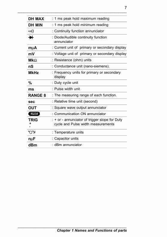
DH MAX : 1 ms peak hold maximum reading
DH MIN : 1 ms peak hold minimum reading
: Continuity function annunciator
: Diode/Audible continuity functionannunciator
mµA : Current unit of primary or secondary display
mV : Voltage unit of primary or secondary display
MkΩ : Resistance (ohm) units
nS : Conductance unit (nano-siemens).
MkHz : Frequency units for primary or secondarydisplay
% : Duty cycle unit
ms : Pulse width unit
RANGE 8 : The measuring range of each function.
sec : Relative time unit (second)
OUT : Square wave output annunciator
: Communication ON annunciator
TRIG+-
: + or - annunciator of trigger slope for Dutycycle and Pulse width measurements
: Temperature units
nµF : Capacitor units
dBm : dBm annunciator

8_______________________________________________________
Chapter 1 Names and Functions of parts_______________________________________________________

9_______________________________________________________
Chapter 2 Measurement Procedures_______________________________________________________
Chapter 2MeasurementProcedures
WARNING
Observe the following precautions to avoid electricshock.There insulating clearance around the terminals isnot safe. Be careful when connecting test leads.The changing of the function switch whenreplacing the test terminals requires disconnectionof the test leads from the item being measured andthen the disconnection of the test leads from theterminals.
Preparation for MeasurementThe safety caps are attached to the test leads. Remove thesecaps before connecting to the instrument.

10_______________________________________________________
Chapter 2 Measurement Procedures_______________________________________________________
NOTE
Key operation Primary display Secondary displayPush SHIFT/PEAK dBmPush SHIFT/PEAK AC Voltage
2.1 Voltage Measurement
DANGER
The maximum input voltage is 1200 VDC, 850Vrms, or, 106V Hz. (600 VDC/rms or 106 V Hzwhen setting the function switch to / mV. )Attempting to measure voltage in excess of themaximum input could destroy the instrument andresult in personal injury or death.To avoid electrical shock, be careful to avoidshorting live lines with the test leads.
2.1.1 AC Voltage Measurement(using V function)
Correct measurement may be impossible in thepresence of strong magnetic fields, such as neartransformers and high-current conductors, or in thepresence of strong electromagnetic fields such asnear radio transmitters.
(1) Set the function switch to V.(2) Connect the black test lead to COM terminal and red test
lead to V Ω terminal.(3) Touch the test leads to the test points and read the display.(4) For manual range selection, press the RANGE/dBm-Ω key
(the AUTO mark disappears). To return to auto-rangingoperation, press and hold the RANGE/dBm-Ω key for morethan 1 second.
(5) Push SHIFT/PEAK key momentarily to enter dBmmeasurement.

11_______________________________________________________
Chapter 2 Measurement Procedures_______________________________________________________
Key operation Primary display Secondary displayPush Dual AC Voltage HzPush Dual dBm AC VoltagePush Dual dBm HzPush Dual AC Voltage
Key operation Primary display Secondary displayPush Hz Hz AC VoltagePush Hz % (Duty cycle) AC VoltagePush Hz ms (Pulse width) AC VoltagePush Hz and holdmore than 1 second
AC Voltage
NOTE
(6) Push DUAL key momentarily to enter multi-display mode.Below, that is DUAL key operation for AC voltage.
(7) Push Hz key momentarily to enter frequency measurementand push this key again to step through Duty cycle, Pulsewidth and frequency measurements.
With the dBm display, pressing the RANGE/dBm-Ω key enables the reference impedance to bechanged. Each time you press the key, theimpedance changes to the next setting: press todisplay the desired value, then leave alone forabout 4 seconds. Measurement restarts with thenew impedance value.
There are twenty reference impedance values toselect from: 4, 8, 16, 32, 50, 75, 93, 110, 125,135, 150, 200, 250, 300, 500, 600, 800, 900,1000, and 1200 ohms.
The default reference impedance is 600 ohms. (Thesetting returns to this value when the instrument ispowered off.)
For Duty cycle and Pulse width tests, pressSHIFT/PEAK key for more 1 second to change thetrigger slope + or -.

12_______________________________________________________
Chapter 2 Measurement Procedures_______________________________________________________
0 to 750 VAC
(+)red
(-)black
2.1.2 DC/AC/AC+DC VoltageMeasurement(using / V or / mV function)
(1) Set the function switch to / V or / mV .(2) Connect the black test lead to COM terminal and red test
lead to V Ω terminal.(3) Touch the test leads to the test points and read the display.(4) For manual range selection, press the RANGE/dBm-Ω key
(the AUTO mark disappears). To return to auto-rangingoperation, press and hold the RANGE/dBm-Ω key for morethan 1 second.

13_______________________________________________________
Chapter 2 Measurement Procedures_______________________________________________________
Key operation Primary display Secondary displayPush SHIFT/PEAK AC Voltage (mV)Push SHIFT/PEAK AC+DC Voltage
(mV)Push SHIFT/PEAK DC Voltage (mV)
Key operation Primary display Secondary displayPush Dual DC Voltage (mV) HzPush Dual dBm DC Voltage (mV)Push Dual DC Voltage (mV) AC Voltage (mV)Push Dual DC Voltage (mV)
Key operation Primary display Secondary displayPush Dual AC Voltage (mV) HzPush Dual dBm AC Voltage (mV)Push Dual AC Voltage (mV) DC Voltage (mV)Push Dual AC Voltage (mV)
Key operation Primary display Secondary displayPush Dual AC+DC Voltage
(mV)Hz
Push Dual dBm AC+DC Voltage(mV)
Push Dual AC+DC Voltage(mV)
AC Voltage (mV)
Push Dual AC+DC Voltage(mV)
DC Voltage (mV)
Push Dual AC+DC Voltage(mV)
(5) Push SHIFT/PEAK key momentarily to step through DC, ACand AC+DC test.
(6) Push DUAL key momentarily to enter multi-display mode.Below, the table is DUAL key operation for DC voltage ormV.
Below, that is DUAL key operation for AC voltage or mV.
Below, the table is DUAL key operation for AC+DC voltageor mV.

14_______________________________________________________
Chapter 2 Measurement Procedures_______________________________________________________
Key operation Primary display Secondary displayPush Hz Hz DC(AC, AC+DC)
Voltage (mV)Push Hz % (Duty cycle) DC(AC, AC+DC)
Voltage (mV)Push Hz ms (Pulse width) DC(AC, AC+DC)
Voltage (mV)Push Hz and holdmore than 1 second
DC(AC, AC+DC)Voltage (mV)
NOTE
(7) Push Hz key momentarily to enter frequency measurementand push this key again to step through Duty cycle, Pulsewidth and frequency measurements.
With the dBm display, pressing the RANGE/dBm-Ω key enables the reference impedance to bechanged. Each time you press the key, theimpedance changes to the next setting: press todisplay the desired value, then leave alone forabout 4 seconds. Measurement restarts with thenew impedance value.
There are twenty reference impedance values toselect from: 4, 8, 16, 32, 50, 75, 93, 110, 125,135, 150, 200, 250, 300, 500, 600, 800, 900,1000, and 1200 ohms.
The default reference impedance is 600 ohms. (Thesetting returns to this value when the instrument ispowered off.)
For Duty cycle and Pulse width tests, pressSHIFT/PEAK key for more 1 second to change thetrigger slope + or -.

15_______________________________________________________
Chapter 2 Measurement Procedures_______________________________________________________
0 to 750 VAC,1000 VDC
(+)red
(-)black
0 to 400 mVAC/DC
(+)red
(-)black

16_______________________________________________________
Chapter 2 Measurement Procedures_______________________________________________________
NOTE
2.2 Resistance and Conductance(1/Ω) Measurement
DANGER
Never apply voltage to the test leads when theResistance functions is selected. Doing so maydamage the instrument and result in personalinjury.To avoid electrical accidents, remove power fromthe circuit before measuring.
2.2.1 Resistance Measurement(1) Set the function switch to Ω .(2) Connect the black test lead to COM terminal and red test
lead to V Ω terminal.(3) Touch the test leads to resistor and read the display.(4) For manual range selection, press the RANGE/dBm-Ω key
(the AUTO mark disappears). To return to auto-rangingoperation, press and hold the RANGE/dBm-Ω key for morethan 1 second.
(5) In Ohm test, press SHIFT/PEAK key momentarily to toggleCONTINUITY function ON/OFF. The continuity range is0-400.0 Ω. Momentarily pushing this key will only turn thebeeper off. While testing continuity, the beeper will soundif the resistance falls below 10 Ω.
When the continuity check function is enabled, abeep sounds if the resistance corresponds to adisplay value of 100 or less in the current range(or a value of 1000 or less in a 40000 countsresolution).In the continuity check function, holding down theRANGE/dBm-Ω key for at least 1 second switchesto auto ranging, and the indication appears,

17_______________________________________________________
Chapter 2 Measurement Procedures_______________________________________________________
0 to 40 MΩ
(+)red
(-)black
PUSH
PUSH
NOTE
2.2.2 Conductance (1/Ω)Measurement
but no continuity check is carried out.
(1) Set the function switch to Ω .(2) Connect the black test lead to COM terminal and red test
lead to V Ω terminal.(3) Open the test leads until the OL is indicated on display.(4) Push RANGE/dBm-Ω key twice to range 7.(5) Push REL key momentarily to zero the residual if necessary.(6) Touch the test leads to resistor and read the display.
Conductance unit is nS (nano-Siemens).

18_______________________________________________________
Chapter 2 Measurement Procedures_______________________________________________________
25 MΩ to
(+)red
(-)black

19_______________________________________________________
Chapter 2 Measurement Procedures_______________________________________________________
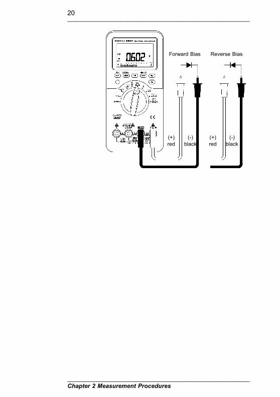
2.3 Diode CheckDANGER
Never apply voltage to the test leads when theDiode Check functions is selected. Doing so maydamage the instrument and result in personalinjury.To avoid electrical accidents, remove power fromthe circuit before measuring.
A good diode allows current to flow in one direction only.To test a diode, turn the power off, remove the diode fromthe circuit, and proceed as follows:
(1) Set the function switch to Hz position.(2) Connect the black test lead to COM terminal and red test
lead to V Ω terminal.(3) Touch the red lead to the positive side of the diode and the
black lead to the negative side. The meter can display diodevoltage drops to approximately 2.5 V. A typical voltage dropis 0.4 to 0.7 V, and the meter will sound a beep to reminduser.
(4) Reverse the test leads and measure the voltage across thediode again. If the diode is:
Good : OL is displayed.Shorted : Near 0 V drop is displayed in both
directions, and the beeper soundscontinuously.
Open : OL is displayed in both directions.(5) Repeat step (3) and (4) for other diodes.
20_______________________________________________________
Chapter 2 Measurement Procedures_______________________________________________________
Forward Bias
(+)red
(-)black
(+)red
(-)black
Reverse Bias

21_______________________________________________________
Chapter 2 Measurement Procedures_______________________________________________________
2.4 Frequency Measurement
DANGER
The maximum input voltage is 1200 VDC, 850Vrms, or 106V/Hz. Attempting to measure voltage inexcess of the maximum input could destroy theinstrument and result in personal injury or death.
(1) Set the function switch to Hz position.(2) Push SHIFT/PEAK key momentarily to enter frequency
counter measurement.(3) The primary display shows test value and the secondary
display shows `- 1 -`. The `- 1 -` means signal divide 1.(4) Connect the black test lead to COM terminal and red test
lead to V Ω terminal.(5) Touch the test leads to signal and read the display.(6) If the reading is unstable or zero, push DUAL key
momentarily to select signal divide 100. Now, the secondarydisplay shows `-100-`.
(7) Touch the test leads to signal and read the display again. Ifthe reading is still unstable, that means the signal is out ofthe specification.
(8) For manual range selection, press the RANGE/dBm-Ω key(the AUTO mark disappears). To return to auto-rangingoperation, press and hold the RANGE/dBm-Ω key for morethan 1 second.

22_______________________________________________________
Chapter 2 Measurement Procedures_______________________________________________________
NOTE
(+)red
(-)black
1 to 10 MHz
PUSH
PUSHPUSH
PUSHPUSH
PUSHPUSH
The test range of divide 1 is from 1 Hz to 200kHz.The test range of divide 100 is from 50 Hz to 10MHz.
Push Hz key momentarily to step through Dutycycle, Pulse width and frequency measurements.
For Duty cycle and Pulse width tests, pressSHIFT/PEAK key for more 1 second to change thetrigger slope + or -.

23_______________________________________________________
Chapter 2 Measurement Procedures_______________________________________________________
NOTE
2.5 Capacitance Measurement
DANGER
Never apply voltage to the µA.mA. .TEMP.OUT terminal. Doing so may damage theinstrument and result in personal injury.
WARNING
Be sure to short the capacitor to discharge itbefore measuring it if it may charged. Doing somay damage the instrument and result in personalinjury.
(1) Set the function switch to position.(2) Connect the red lead to µA.mA. .TEMP. OUT
terminal, and black lead in COM terminal.(3) Open the test leads, then push REL key momentarily to zero
the residual.(4) Connect the test leads across the capacitor and read the
display.
Observe polarity when measuring the polarizedcapacitors.
When testing low-capitance devices, noiseintroduced into the test leads from the human bodymay prevent the measured value from stabilizing.If this occurs, use the optional 9617 CLIP ONBASE or the optional 9618 CLIP-TYPE LEADand keep hands away from the leads duringmeasurement.

24_______________________________________________________
Chapter 2 Measurement Procedures_______________________________________________________
0 to 9999µ F
(+)red
(-)black

25_______________________________________________________
Chapter 2 Measurement Procedures_______________________________________________________
Key operation Primary display Secondary displayPush SHIFT/PEAK ACµAPush SHIFT/PEAK AC+DCµAPush SHIFT/PEAK DCµA
2.6 Current MeasurementWARNING
Do not use the tester to measure current when theelectric potential is 600 V or greater.The current function overload protection trips at600 VAC.To avoid electrical accidents, remove power fromthe circuit before measuring.Do not apply voltage while a current range isselected. Applying voltage may result in damage tothe instrument, or a serious accident.
2.6.1 µA Measurement (400 µA,4000 µA)
(1) Set the function switch to / µA .(2) Connect the black test lead to COM terminal and red test
lead to µA.mA. .TEMP. OUT terminal.(3) Touch the test leads to the test points and read the display.(4) For manual range selection, press the RANGE/dBm-Ω key
(the AUTO mark disappears). To return to auto-rangingoperation, press and hold the RANGE/dBm-Ω key for morethan 1 second.
(5) Push SHIFT/PEAK key momentarily to step through DC, ACand AC+DC test.

26_______________________________________________________
Chapter 2 Measurement Procedures_______________________________________________________
Key operation Primary display Secondary displayPush Dual DCµA HzPush Dual DCµA ACµAPush Dual DCµA
Key operation Primary display Secondary displayPush Dual ACµA HzPush Dual ACµA DCµAPush Dual ACµA
Key operation Primary display Secondary displayPush Dual AC+DCµA HzPush Dual AC+DCµA ACµAPush Dual AC+DCµA DCµAPush Dual AC+DCµA
Key operation Primary display Secondary displayPush Hz Hz DC (AC, AC+DC)µAPush Hz % (Duty cycle) DC (AC, AC+DC)µAPush Hz ms (Pulse width) DC (AC, AC+DC)µAPush Hz and holdmore than 1 second
DC (AC, AC+DC)µA
NOTE
(6) Push DUAL key momentarily to enter multi-display mode.Below, the table is DUAL key operation for DC mA.
Below, the table is DUAL key operation for ACµA.
Below, the table is DUAL key operation for AC+DCµA.
(7) Push Hz key momentarily to enter frequency measurementand push this key again to step through Duty cycle, Pulsewidth and frequency measurements.
For Duty cycle and Pulse width tests, pressSHIFT/PEAK key for more 1 second to change thetrigger slope + or -.

27_______________________________________________________
Chapter 2 Measurement Procedures_______________________________________________________
0 to 4 mA DC/AC
(+)red
(-)black
Key operation Primary display Secondary displayPush SHIFT/PEAK AC mAPush SHIFT/PEAK AC+DC mAPush SHIFT/PEAK DC mA
2.6.2 mA Measurement(40 mA,400 mA)
(1) Set the function switch to / mA.A .(2) Connect the black test lead to COM terminal and red test
lead to µA.mA. .TEMP. OUT terminal.(3) Touch the test leads to the test points and read the display.(4) For manual range selection, press the RANGE/dBm-Ω key
(the AUTO mark disappears). To return to auto-rangingoperation, press and hold the RANGE/dBm-Ω key for morethan 1 second.
(5) Push SHIFT/PEAK key momentarily to step through DC, ACand AC+DC test.

28_______________________________________________________
Chapter 2 Measurement Procedures_______________________________________________________
Key operation Primary display Secondary displayPush Dual DC mA HzPush Dual DC mA AC mAPush Dual DC mA
Key operation Primary display Secondary displayPush Dual AC mA HzPush Dual AC mA DC mAPush Dual AC mA
Key operation Primary display Secondary displayPush Dual AC+DC mA HzPush Dual AC+DC mA AC mAPush Dual AC+DC mA DC mAPush Dual AC+DC mA
Key operation Primary display Secondary displayPush Hz Hz DC (AC, AC+DC)
mAPush Hz % (Duty cycle) DC (AC, AC+DC)
mAPush Hz ms (Pulse width) DC (AC, AC+DC)
mAPush Hz and holdmore than 1 second
DC (AC, AC+DC)mA
NOTE
(6) Push DUAL key momentarily to enter multi-display mode.Below, the table is DUAL key operation for DC mA.
Below, the table is DUAL key operation for AC mA.
Below, the table is DUAL key operation for AC+DC mA.
(7) Push Hz key momentarily to enter frequency measurementand push this key again to step through Duty cycle, Pulsewidth and frequency measurements.
For Duty cycle and Pulse width tests, pressSHIFT/PEAK key for more 1 second to change thetrigger slope + or -.

29_______________________________________________________
Chapter 2 Measurement Procedures_______________________________________________________
0 to 400 mA DC/AC
(+)red
(-)black
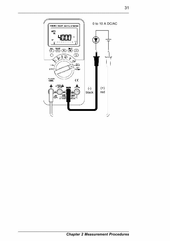
2.6.3 A Measurement (10 A)
WARNING
The maximum input current in the 10 A range isDC 10 A or AC 10 A rms. Never exceed this limit,as doing so could result in destruction of theinstrument and personal injury or death.
(1) Set the function switch to / mA.A .(2) Connect the black test lead to COM terminal and red test
lead to A terminal.(3) Touch the test leads to the test points and read the display.

30_______________________________________________________
Chapter 2 Measurement Procedures_______________________________________________________
Key operation Primary display Secondary displayPush SHIFT/PEAK AC APush SHIFT/PEAK AC+DC APush SHIFT/PEAK DC A
Key operation Primary display Secondary displayPush Dual DC A HzPush Dual DC A AC APush Dual DC A
Key operation Primary display Secondary displayPush Dual AC A HzPush Dual AC A DC APush Dual AC A
Key operation Primary display Secondary displayPush Dual AC+DC A HzPush Dual AC+DC A AC APush Dual AC+DC A DC APush Dual AC+DC A
Key operation Primary display Secondary displayPush Hz Hz DC (AC, AC+DC) APush Hz % (Duty cycle) DC (AC, AC+DC) APush Hz ms (Pulse width) DC (AC, AC+DC) APush Hz and holdmore than 1 second
DC (AC, AC+DC) A
NOTE
(4) Push SHIFT/PEAK key momentarily to step through DC, ACand AC+DC test.
(5) Push DUAL key momentarily to enter multi-display mode.Below, the table is DUAL key operation for DC A.
Below, the table is DUAL key operation for AC mA.
Below, the table is DUAL key operation for AC+DC mA.
(6) Push Hz key momentarily to enter frequency measurementand push this key again to step through Duty cycle, Pulsewidth and frequency measurements.
For Duty cycle and Pulse width tests, pressSHIFT/PEAK key for more 1 second to change thetrigger slope + or -.
31_______________________________________________________
Chapter 2 Measurement Procedures_______________________________________________________
0 to 10 A DC/AC
(+)red
(-)black

32_______________________________________________________
Chapter 2 Measurement Procedures_______________________________________________________
NOTE
2.7 Temperature Measurement
DANGER
Never apply voltage to the µA.mA. .TEMP.OUT terminal. Doing so may damage theinstrument and result in personal injury.
(1) Turn the function switch to the TEMP/ range.(2) Plug the temperature probe (option: 9180, 9181, 9182,
9183) into µA.mA. .TEMP. OUT (the plus side)and COM (the minus side) terminal.
(3) Press DUAL key to toggle between (Celsius) and(Fahrenheit) on primary display.
(4) Attach the thermocouple to the heated source.(5) Read the display.
The following expression converts degreesFahrenheit into degrees Celsius.
= 1.8 X + 32
Check that the polarity of temperature probeconnections is correct.
Remove dirt from the surface to be measured, andhold the temperature probe firmly against thesurface.

33_______________________________________________________
Chapter 2 Measurement Procedures_______________________________________________________
PUSH

34_______________________________________________________
Chapter 2 Measurement Procedures_______________________________________________________
NOTE
2.8 Square Wave OutputDANGER
Never apply voltage to the µA.mA. .TEMP.OUT terminal. Doing so may damage theinstrument and result in personal injury.
(1) Turn the function switch to the TEMP/ range.(2) Push SHIFT/PEAK key momentarily to select square wave
output function.(3) The default output :FREQUENCY= 600 Hz, Duty cycle =
50 %.(4) Push Hz key momentarily to select 16 kinds of frequency.
Press and hold this key, the frequency selection will rolledup continuous.
(5) Push DUAL key momentarily to adjust duty cycle of outputfrequency.Press and hold this key, the duty cycle adjustment willrolled up continuous.
(6) The feature of auto power off will be disabled in thisfunction.
A voltage is output from the instant at which thepulse output function is selected.
There are 16 selectable frequencies: 0.5, 1, 2, 10,50, 60, 75, 100, 150, 200, 300, 600, 1200, 1600,2400, and 4800 Hz.

35_______________________________________________________
Chapter 2 Measurement Procedures_______________________________________________________
Amp./Converter
Test/Controlinstrument
-
+

36_______________________________________________________
Chapter 2 Measurement Procedures_______________________________________________________
NOTE
2.9 Timer + Signal Output
DANGER
Never apply voltage to the µA.mA. .TEMP.OUT terminal. Doing so may damage theinstrument and result in personal injury.
(1) Turn the function switch to the TEMP/ range.(2) Push and hold SHIFT/PEAK key for 1 sec to select timer
function.(3) The signal output is defined from Low level to High level.
The secondary display shown Lo - Hi to indicate it.(4) Push DUAL key momentarily to select the status of signal
output from High to Low level , Pulse of Low to High,Pulse of high to low and Low to High level outputs.
(5) The primary display is indicate the timer value and the unitis second(s).Push HOLD/MAX MIN key momentarily to select whichdigits will be adjusted by Pushing the REL key.
(6) Push Hz key momentarily to start timer after setting thetimer.Push this key momentarily again to stop timer.
(7) Push SHIFT/PEAK key momentarily to reset timer andoutput level. The timer will be reset to previous valuedefined by users. The output level will be reset to relativelevel.
The meter will send a level (or pulse) and sound abeep after the timer reaches zero.
The feature of auto power off will be disabled inthis function.

37_______________________________________________________
Chapter 2 Measurement Procedures_______________________________________________________
Controlinstrument
PUSH

38_______________________________________________________
Chapter 2 Measurement Procedures_______________________________________________________

39_______________________________________________________
Chapter 3 Special Functions Instruction_______________________________________________________
Chapter 3Special Functions
Instruction
This multi-meter provides operators with various functionsincluding:
Dynamic RecordingData Hold / Refresh HoldRelativeAnalog Bar graphAuto Power Off and Sleep ModeDisplay Value Selection FunctionDemonstrate Annunciator of Display(LCD Display Check Function)Backlight LCD for easy reading in the darkContinuity Function For Ohms MeasurementCombination Display1 ms Peak HoldCommunication Function (RS-232C)Warning Function for Incorrect Current Input TerminalConnectionPower-on Option

40_______________________________________________________
Chapter 3 Special Functions Instruction_______________________________________________________
NOTE
3.1 Dynamic RecordingThe dynamic recording mode can be used to catchintermittent turn on or turn off surges, verify performance,measure while you are away, or take readings while you areoperating the equipment under test and can not watch themeter.The average reading is useful for smoothing out unstable orchanging inputs, estimating the percentage of time a circuitis operated, or verifying circuit performance.The operational procedures are described below:
(1) Press HOLD/MAX MIN for more than 1 second to enter thedynamic recording. The present value is stored to memoriesof maximum, minimum and average. MAX AVG MINannunciator will be on.
(2) Press this key for more than 1 second to exit recordingmode.
(3) Press this key momentarily to cycle through maximum,minimum, average and present readings. The MAX, MIN,AVG or MAX AVG MIN annunciator turns on respectively toindicate which value is being displayed.
(4) The beeper sounds when a new maximum or minimumvalue is recorded.
(5) If an overload is recorded the averaging function will stop.An average value becomes OL (overload).
(6) The secondary digits show the relative stamping time forMAX, MIN, AVG reading.
In dynamic recording, the auto power off feature isdisabled. and the will be turned off.Selecting dynamic recording in auto range, it willrecord the value of MAX, MIN or AVG fordifferent ranges.The recording speed of dynamic recording is about100 milli-seconds (0.1 second).The average value is the true average of allmeasured values taken since the recording modewas entered.The unit of relative time is second, and themaximum display is 99,999 sec.

41_______________________________________________________
Chapter 3 Special Functions Instruction_______________________________________________________
PUSH1sec
PUSH
PUSHPUSH
1sec
PUSH1sec
PUSH
PUSHPUSH1sec
NOTE
3.2 Data Hold/Refresh Hold3.2.1 Data Hold
The data hold function allows operators to hold thedisplayed digital value, while the analog bar graph continuesshowing the present readings. Press HOLD/MAX MIN keyto enter the data hold mode, and the DH will be displayed.
Press the key again to exit. The present reading is nowshown.
The analog bar graph continues showing thepresent readings

42_______________________________________________________
Chapter 3 Special Functions Instruction_______________________________________________________
NOTE
NOTE
3.2.2 Refresh Hold
3.3 Relative (ZERO)
You can use the power-on option to set the Refresh Holdwhen you are working on a difficult measuring field. Thisfunction will freeze measuring value automatically, andsound a tone to remind user. The operation of push key issame as the operation of Data hold.
If the reading is unstable, the display may not beupdated.In the voltage, current, and capacitance functions,when the measured value corresponds to 80 counts(800 counts in the case of 40000 countsresolution), the display value is not updated.In the resistance and diode functions, the displayvalue is not updated in the overload OL state,and when the test leads are open-circuit.
The relative function subtracts a stored value from thepresent measurement and displays the result.
(1) Press REL key momentarily to set the relative mode. Thissets the display to zero and stores the displayed reading as areference value, also will be displayed.
(2) Both auto or manual range can set relative mode. Therelative mode can't be set when an overload has occurred.
(3) Press this key again to exit the relative mode.(4) In the relative mode, the zero point of bar graph is set to
middle position.(5) When the Ohm measurement mode is entered, the display
will reads a non zero value due to the presence of testleads. You can use the relative function to Zero-Adjust thedisplay.
In the case of an overload ( OL indication), therelative function does not operate.The relative function is ended by changing thefunction, pressing the SHIFT/PEAK key,RANGE/dBm-Ω key, DUAL key, or Hz key, or bypowering off the instrument.

43_______________________________________________________
Chapter 3 Special Functions Instruction_______________________________________________________
3.4 Analog Bar Graph
3.5 Auto Power Off and SleepMode
The analog bar graph display provides a 21 segments analogreading representation. The unit of the bar graph is 50counts/bar (40,000 counts resolution: 500 counts/bar) exceptwhen in the RELative mode. The unit of the bar graph is100 counts/bar in the RELative mode. For increasedsensitivity, the display of bar graph moves across the scalefour times for each range. The bar returns to 0 (wrapsaround) for 1000, 2000, 3000, 4000 counts (40,000 countsresolution: 10,000, 20,000, 30,000, 40,000 counts).
Two steps for power saving:(1) The instrument may enter sleep mode within 15 minutes, if
none of the following happens.Push keys are used.Measurement function is changed.Dynamic recording is set.1 ms peak hold is set.Disable auto power off with power-on option.
(2) In sleep mode, the LCD will display a blinking signal.To wake-up sleep mode, press any push key for morethan 0.5 sec or rotate function switch.Without waking up, after 15 minutes, the meter willautomatically shut off completely.
(3) You must turn the function switch to the OFF position, thenturn on again to activate the meter after auto power off.DISABLE AUTO POWER OFFWhen the meter is to be used for long periods of time, theoperator may want to disable the auto power off. Once the autopower off function is disabled, the meter will stay oncontinuously. To shut off the meter by turning the functionswitch to the off position.To activate this function, press and hold the SHIFT/PEAK keybefore switching the meter power on. When all annunciatorsare displayed, press any key momentarily to exit demonstrationmode, and the annunciator will be off.

44_______________________________________________________
Chapter 3 Special Functions Instruction_______________________________________________________
NOTE
NOTE
NOTE
3.6 Display Value SelectionFunction
3.7 Demonstrate Annunciator
All settings are reset after returning from sleepmode or auto power off.
The functions in this section are disabled when thepulse output function, timer + signal outputfunction, recording function, or 1 ms peak holdfunction is active.
It is possible to select either 4000 or 40000 as the maximumdisplay value, using either of the following methods.
(1) After powering on the instrument, hold down the backlightkey for more than 1 second. Holding down the backlightkey once more for more than 1 second returns to theprevious display value.
(2) Power on the instrument while holding down theRANGE/dBm-Ω key (power on options). This selects the40000 display value setting.
When the dual display function is active, thischanges the display value for both the first andsecond displays.
When the instrument is powered on in the usualway (without using the power on options), amaximum display value of 4000 is selected.
The display value for the capacitance measurementfunction does not change (fixed at 4000).
To demonstrate the annunciators, press SHIFT/PEAK keyand turn on the meter simultaneously. All annunciators willbe displayed. Press any key to exit demonstration mode.
This operation cancels the power save function. Torenewable the power save function, power theinstrument off and on again.

45_______________________________________________________
Chapter 3 Special Functions Instruction_______________________________________________________
NOTE
3.8 Backlight Display for EasyReading in The Dark
3.9 Continuity Function for OHMSMeasurement
Press Backlight (yellow) key for more than 1 second totoggle backlight ON/OFF.Backlight turns off automatically after 30 seconds.To disable backlight(off automatically after 30 seconds),please refer to power-on option introduction.
In Ohm test, press SHIFT/PEAK key momentarily to toggleCONTINUITY functionON/OFF. The continuity range is 0-400.0 Ω Momentarilypushing this key will only turn the beeper on/off.While testing continuity, the beeper will sound if theresistance falls below 10 Ω. For other range, the beeper willsound if the resistance falls below 100 counts (40,000counts resolution: 1,000 counts).
After starting the conductivity check functionbased on resistance measurement, even pressingthe SHIFT/PEAK key to exit the function does notreturn to auto ranging. To set auto ranging, holddown the RANGE/dBm-Ω key for at least 1second.
In the continuity check function, holding down theRANGE/dBm-Ω key for at least 1 second switchesto auto ranging, and the indication appears, butno continuity check is carried out. (The beeperdoes not sound.)

46_______________________________________________________
Chapter 3 Special Functions Instruction_______________________________________________________
3.10 Combination Display
3.11 1 ms Peak Hold
The frequency measuring mode helps detect the presence ofharmonic currents in neutral conductors and determineswhether these neutral currents are the result of unbalancedphases or non-linear loads.For Voltage or Current test, press Hz key momentarily toenter Frequency test. Voltage or Current will display on thesecondary display, the frequency will display on the primarydisplay. Press this key again to step through Frequency,Duty cycle and pulse width tests. This allows simultaneouslymonitor the current levels and frequency(or Duty Cycle, orpulse width).Press Hz key more than 1 second to return to Voltage orCurrent measurement.Please refer to the Chapter 2 Measurement Procedures, thatwill detail for other combination display.
You can use this Meter to analyze components such aspower distribution transformers and power factor correctioncapacitors. The additional features allow the measurement ofthe half-cycle peak voltage by using the 1 ms peak holdfeature. This allows the determination of the crest factor:
Crest factor = Peak value/True rms value
(1) Press SHIFT/PEAK key more than 1 second to toggle 1 mspeak hold mode ON/OFF.
(2) Press HOLD/MAX MIN key momentarily to show peak + orpeak- value after setting the peak mode.The display shows DH MAX to indicate the PEAK + andshows DH MIN to indicate the PEAK -. See Figure 15.
(3) The secondary digits show the relative stamping time forPeak reading.
(4) If the reading is OL, then you can push RANGE/dBm-Ω keymomentarily to change measuring range and re-start thePEAK measurement after setting the peak mode.
(5) Press DUAL key momentarily to re-start the 1 ms peak holdagain after setting peak mode.

47_______________________________________________________
Chapter 3 Special Functions Instruction_______________________________________________________
NOTE
NOTE
To COM1 orCOM2 ofcomputer
3.12 Communication (RS-232C)
The accuracy figures in 1ms peak hold functionare determined with DC coupling mode (DC isdisplayed.). (See 4.2 Accuracy Chart.)
Exiting the 1 ms peak hold function switches toauto ranging.
This meter has a communication capability. This functionwill assist user to recording and keeping data easy.We have offer 3852 to optional accessories. The 3852include a cable with phonic receiver and a software disc.Please refer following procedures If you want tocommunicate with personal computer.
(1) Push and hold the DUAL key then turn the function switchfrom off position to any function, wait 1 second, thenrelease the push key. You will find that the annunciator of
is light on the display.(2) Fixes one side of cable to the holster of meter and connect
the 9 pin`s terminal of cable to communication port 1 or 2of personal computer. See the Figure below.
(3) Execute the software to take the data for your necessarydata.
See the 3852 instruction manual

48_______________________________________________________
Chapter 3 Special Functions Instruction_______________________________________________________
NOTE
3.13 Warning Function forIncorrect Current InputTerminal Connection
3.14 Power-on Options
This instrument has a safety function to prevent accidentswhen measuring voltages. Under the following conditions,Error flashes in the first display and the beeper sounds.The function switch is set to a position other than /mA.A, and a test lead is connected to the A terminal.
This function does not operate if the fuseconnected to the A terminal has blown.
SELECTING POWER-ON OPTIONS
Some options can be selected only when you turn the meteron.To select power-on options, press and hold push key whileturning the function switch to any on position. Power-onoptions remain selected until the meter is turned off.
SHIFT/PEAKDemonstrate AnnunciatorsTo demonstrate the annunciators, The entire annunciatorswill be displayed. Press the key again to exit demonstrationmode.Disable auto-power offIn general, the auto power off function will turn the meteroff if neither function switch nor push key is activated for15 minutes. When auto power off is disabled, the meter willstay on continuously.Auto-power off will be auto disabled in Dynamic Recording.
HOLD/MAX MINEnable Refresh Hold.

49_______________________________________________________
Chapter 3 Special Functions Instruction_______________________________________________________
RELDisable beeper function.Turns off all beeper functions.
RANGE/dBm- ΩSelect 4,000/40,000 counts resolution.In general, The meter is 4,000 counts (3 3/4 digits)resolution and the response time is 3.3 times per second. Bythis option, the meter can be changed to 40,000 counts (43/4 digits) resolution and the response time can be updatedto one time per second.
Backlight (Yellow)Disable backlight turns off automatically after 30seconds.
DUALSet Computer Interface.Turn on Data output function by RS-232C interface. TheRS232 annunciator will turn lit.

50_______________________________________________________
Chapter 3 Special Functions Instruction_______________________________________________________

51_______________________________________________________
Chapter 4 Specifications_______________________________________________________
Measurement System Dual integration
AC MeasurementSystem
True RMS measurement
Type of Display LCD,Backlight
Maximummeasurement count
40000count, 4000count
Polarity Display Automatically lights only when '-'.
Battery Low Display The indicator flashes.
Range Selection Automatic or Manual
Function Switch Rotary switch
Sampling Rate Approx. 3 times/s (except Ω and Hz,4000count)Approx. 0.8 times/s (except Ω and Hz,40000count)Approx. 0.8 times/s (Ω and Hz)0.25 to 4 times/s (Duty cycle and pulsewidth)Approx. 20 times/s (bar graph)
Location for use Indoor,altitude up to 2000 m (6562 feet)
Operating Temperatureand Humidity Range
0 to 50 (32 to 122 ),80% RH or less (no condensation)
Storage Temperatureand Humidity Range
-20 to 60 (-4 to 140 ),80% RH or less (no condensation)
TemperatureCharacteristic
0.15 x (measurement accuracy)/ ( )
Power Supply one 6F22 manganese battery
Chapter 4Specifications
4.1 General Specification

52_______________________________________________________
Chapter 4 Specifications_______________________________________________________
Rated supply voltage 9 VDC x 1
Continuous operatingtime
Approx. 50 h (VDC, manganese battery)Approx. 90 h (VDC, alkaline battery)
Maximum input voltage VDC, VAC, V(AC+DC):40 mV to 400 mV range:600 VDC/ACrms(sin)except 40 mV to 400 mV range:1200 VDC/850 VACrms(sin)
ADC,AAC,A(AC+DC):400µA to 400 mA range:Fuse protection 1 A/600 VAC4 A to 10 A range:Fuse protection 15 A/600 VAC
Ω,C,Continuity check/Diode check: 600VDC/600 VACrms(sin)Hz:1200 VDC/850 VACrms(sin) or 106 V HzTEMP:600 VDC/600 VACrms(sin)
Dielectric Strength 6 kVACrms sin for 50/60 Hz, 1 minute(terminal to housing)
Noise Resistance NMRR :VDC minimum -60 dB (50 /60 Hz)CMRR :VDC minimum -120 dB (50/60 Hz)
VAC minimum -60 dB (50/60 Hz)
Power Rated 40 mVA typ.(VDC, supply voltage 9.0 V)
110 mVA typ.(Hz, supply voltage 9.0 V)
Maximum rated power 150 mVA
Battery consumptiondisplay
The indicator flashes when Approx. 7.2V or less.
Dimensions and Mass Approx. 90W x 192H x 37D mmApprox. 3.54"W x 7.56"H x 1.46"D(not including protrusion)Approx. 440 g,15.5 oz (body,battery)Approx. 640 g,22.6 oz(body,holster,battery)

53_______________________________________________________
Chapter 4 Specifications_______________________________________________________
Accessories 3851-10 TEST LEADProtective holsterInstruction manualone 6F22 manganese battery (built intoinstrument)
Options 3852 RS-232C PACKAGE3853 CARRYING CASE9180 SHEATH TYPE TEMPERATUREPROBE9181 SURFACE TEMPERATURE PROBE9182 SHEATH TYPE TEMPERATUREPROBE9183 SHEATH TYPE TEMPERATUREPROBE9472 SHEATH TYPE TEMPERATUREPROBE9473 SHEATH TYPE TEMPERATUREPROBE9474 SHEATH TYPE TEMPERATUREPROBE9475 SHEATH TYPE TEMPERATUREPROBE9476 SURFACE TYPE TEMPERATUREPROBE9617 CLIP ON BASE9618 CLIP-TYPE LEAD
Applicable Standards Safety : EN61010-1:2001Pollution Degree 2, Measurementcategory II (1000 V),category III(600 V) (anticipated transientovervoltage 6000 V)
EMC : EN61326:1997+A1:1998+A2:2001
54_______________________________________________________
Chapter 4 Specifications_______________________________________________________
NOTE
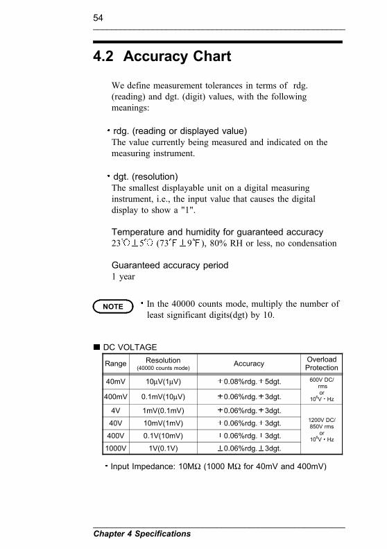
Range Resolution(40000 counts mode)
Accuracy OverloadProtection
40mV 10µV(1µV) 0.08%rdg. 5dgt. 600V DC/rmsor
106V Hz400mV 0.1mV(10µV) 0.06%rdg. 3dgt.
4V 1mV(0.1mV) 0.06%rdg. 3dgt.1200V DC/850V rms
or106V Hz
40V 10mV(1mV) 0.06%rdg. 3dgt.
400V 0.1V(10mV) 0.06%rdg. 3dgt.
1000V 1V(0.1V) 0.06%rdg. 3dgt.
Input Impedance: 10MΩ (1000 MΩ for 40mV and 400mV)
4.2 Accuracy Chart
We define measurement tolerances in terms of rdg.(reading) and dgt. (digit) values, with the followingmeanings:
rdg. (reading or displayed value)The value currently being measured and indicated on themeasuring instrument.
dgt. (resolution)The smallest displayable unit on a digital measuringinstrument, i.e., the input value that causes the digitaldisplay to show a "1".
Temperature and humidity for guaranteed accuracy23 5 (73 9 ), 80% RH or less, no condensation
Guaranteed accuracy period1 year
In the 40000 counts mode, multiply the number ofleast significant digits(dgt) by 10.
DC VOLTAGE

55_______________________________________________________
Chapter 4 Specifications_______________________________________________________
RangeResolution(40000 counts
mode)
Accuracy OverloadProtection50/60Hz 45Hz to 5kHz 5kHz to 20kHz
40mV 10µV(1µV) 0.7%rdg. 5dgt. 1.5%rdg. 5dgt. 2%rdg. 5dgt. 600V DC/rmsor
106V Hz400m 0.1mV(10µV) 0.7%rdg. 5dgt. 1.5%rdg. 5dgt. 2%rdg. 5dgt.
4V 1mV(0.1mV) 0.7%rdg. 5dgt. 1.5%rdg. 5dgt. 2%rdg. 5dgt.1200V DC/850V rms
or106V Hz
40V 10mV(1mV) 0.7%rdg. 5dgt. 1.5%rdg. 5dgt. 2%rdg. 5dgt.
400V 0.1V(10mV) 0.7%rdg. 5dgt. 1.5%rdg. 5dgt. 2%rdg. 5dgt.
750V 1V(0.1V) 0.7%rdg. 5dgt. 3%rdg. 5dgt. -
Input Impedance: 10MΩ (1000MΩ for 40mV and 400mV)Crest factor: 3
RangeResolution
(40000counts mode)
Accuracy OverloadProtection50/60Hz 45Hz to 5kHz 5kHz to 20kHz
40mV 10µV(1µV) 0.8%rdg. 10dgt. 1.6%rdg. 10dgt. 2.1%rdg. 10dgt. 600V DC/rmsor
106V Hz400m 0.1mV(10µV) 0.8%rdg. 10dgt. 1.6%rdg. 10dgt. 2.1%rdg. 10dgt.
4V 1mV(0.1mV) 0.8%rdg. 10dgt. 1.6%rdg. 10dgt. 2.1%rdg. 10dgt.1200V DC/850V rms
or106V Hz
40V 10mV(1mV) 0.8%rdg. 10dgt. 1.6%rdg. 10dgt. 2.1%rdg. 10dgt.
400V 0.1V(10mV) 0.8%rdg. 10dgt. 1.6%rdg. 10dgt. 2.1%rdg. 10dgt.
750V 1V(0.1V) 0.8%rdg. 10dgt. 3%rdg. 10dgt. -
Input Impedance: 10MΩ (1000MΩ for 40mV and 400mV)Crest factor: 3
RangeResolution(40000 counts
mode)Accuracy Input impedance Overload
Protection
400µA 0.1µA(10nA) 0.2%rdg. 3dgt. Approx.100Ω
1A/600VAC,High Energy
Fuse
4000µA 1µA(0.1µA) 0.2%rdg. 3dgt. Approx.100Ω
40mA 10µA(1µA) 0.2%rdg. 3dgt. Approx.1Ω
400mA 0.1mA(10µA) 0.2%rdg. 3dgt. Approx.1Ω
4A 1mA(0.1mA) 0.2%rdg. 3dgt. Approx.0.01Ω 15A/600VAC,High Energy
Fuse10A 10mA(1mA) 0.2%rdg. 3dgt. Approx.0.01Ω
10 A continuous.
AC VOLTAGE (TRUE RMS : From 5% to 100% of range. )
AC+DC VOLTAGE (TRUE RMS : From 5% to 100% of range.)
DC CURRENT

56_______________________________________________________
Chapter 4 Specifications_______________________________________________________
RangeResolution(40000 counts
mode)
Accuracy45 Hz to 2 kHz Input impedance Overload
Protection
400µA 0.1µA(10nA) 1.0%rdg. 5dgt. Approx.100Ω
1A/600VAC,High Energy
Fuse
4000µA 1µA(0.1µA) 1.0%rdg. 5dgt. Approx.100Ω
40mA 10µA(1µA) 1.0%rdg. 5dgt. Approx.1Ω
400mA 0.1mA(10µA) 1.0%rdg. 5dgt. Approx.1Ω
4A 1mA(0.1mA) 1.0%rdg. 5dgt. Approx.0.01Ω 15A/600VAC,High Energy
Fuse10A 10mA(1mA) 1.0%rdg. 5dgt. Approx.0.01Ω
10 A continuous.Crest factor: 3
RangeResolution(40000 counts
mode)
Accuracy45 Hz to 2 kHz Input impedance Overload
Protection
400µA 0.1µA(10nA) 1.2%rdg. 10dgt. Approx.100Ω
1A/600VAC,High Energy
Fuse
4000µA 1µA(0.1µA) 1.2%rdg. 10dgt. Approx.100Ω
40mA 10µA(1µA) 1.2%rdg. 10dgt. Approx.1Ω
400mA 0.1mA(10µA) 1.2%rdg. 10dgt. Approx.1Ω
4A 1mA(0.1mA) 1.2%rdg. 10dgt. Approx.0.01Ω 15A/600VAC,High Energy
Fuse10A 10mA(1mA) 1.2%rdg. 10dgt. Approx.0.01Ω
10 A continuous.Crest factor: 3
Range Resolution Accuracy Overload Protection
-80.79dBmto
81.48dBm0.01dBm 0.3dBm
1.600V DC or 600V rmsfor mV input
2.1200V DC or 850V rmsfor V input
or106V Hz
Reference Impedance:4,8,16,32,50,75,93,110,125,135,150,200,250,300,500,600,800,900,1000,1200 ΩA voltage(ACV, DCV or AC+DCV) measuring is converted todBm using the following formula:
dBm = 10 log10 (1000 X V X V/reference impedance)
AC CURRENT (TRUE RMS: From 5% to 100% of range.)
AC+DC CURRENT (TRUE RMS: From 5% to 100% of range.)
dBm (TRUE RMS: From 5% to 100% of ACV range.)

57_______________________________________________________
Chapter 4 Specifications_______________________________________________________
NOTE
VOLTAGE (DC coupling only)
Range Resolution(40000 counts mode)
Accuracy OverloadProtection
40mV 10µV(1µV) 2%rdg. 43dgt. 600V DC/rmsor
106V Hz400mV 0.1mV(10µV) 2%rdg. 43dgt.
4V 1mV(0.1mV) 2%rdg. 43dgt.1200V DC/850V rms
or106V Hz
40V 10mV(1mV) 2%rdg. 43dgt.
400V 0.1V(10mV) 2%rdg. 43dgt.
1000V 1V(0.1V) 2%rdg. 43dgt.
Input Impedance: 10MΩ (1000MΩ for 40mV and 400mV)
CURRENT (DC coupling only)
Range Resolution(40000 counts mode)
Accuracy Inputimpedance
OverloadProtection
400µA 0.1µA(10nA) 2%rdg. 43dgt. Approx.100Ω1A/600VAC,High Energy
Fuse
4000µA 1µA(0.1µA) 2%rdg. 43dgt. Approx.100Ω
40mA 10µA(1µA) 2%rdg. 43dgt. Approx.1Ω
400mA 0.1mA(10µA) 2%rdg. 43dgt. Approx.1Ω
4A 1mA(0.1mA) 2%rdg. 43dgt. Approx.0.01Ω 15A/600VAC, HighEnergyFuse
10A 10mA(1mA) 2%rdg. 43dgt. Approx.0.01Ω
1 ms PEAK HOLD
Specified accuracy 40 counts (40000 countsmode : 400 counts) for changes > 1 ms induration in DC coupling (DC is displayed.).

58_______________________________________________________
Chapter 4 Specifications_______________________________________________________
Range Resolution(40000 counts mode)
Accuracy Max. TestVoltage
OverloadProtection
400Ω 0.1Ω(0.01Ω) 0.2%rdg. 3dgt. 3.3V(Max.)
600VDC/rms
4kΩ 1Ω(0.1Ω) 0.2%rdg. 3dgt. 1.28V(Max.)
40kΩ 10Ω(1Ω) 0.2%rdg. 3dgt. 1.28V(Max.)
400kΩ 100Ω(10Ω) 0.2%rdg. 3dgt. 1.28V(Max.)
4MΩ 1kΩ(0.1kΩ) 0.2%rdg. 3dgt. 1.28V(Max.)
40MΩ 10kΩ(1kΩ) 1%rdg. 5dgt. 1.28V(Max.)
40nS 0.01nS(0.001nS) 1%rdg. 10dgt. 1.28V(Max.)
Instant Continuity: Built-in buzzer sounds when resistance isless than 100 counts (40000 counts mode: 1000 counts).With regard to conductance measurement, use Relative modeto zero residual.
Range Resolution Accuracy OverloadProtection
4nF 1pF 2.5%rdg. 6dgt.
600VDC/rms
40nF 10pF 2.5%rdg. 6dgt.
400nF 0.1nF 2%rdg. 4dgt.
4µF 1nF 5%rdg. 4dgt.
40µF 10nF 5%rdg. 4dgt.
400µF 0.1µF 5%rdg. 4dgt.
9999µF 1µF 6%rdg. 4dgt.>2mF, NO Spec.
With film capacitor or better, use Relative mode to zeroresidual.
RangeResolution(40000 counts
mode)Accuracy Test
CurrentTest
VoltageOverloadProtection
Diode 1mV(0.1mV) 1.0%rdg.2dgt.
Approx.1.65mA <3.3V 600V DC/
rms
RESISTANCE
CAPACITOR
DIODE CHECK

59_______________________________________________________
Chapter 4 Specifications_______________________________________________________
RangeResolution(40000 counts
mode)Accuracy Test
CurrentTest
VoltageOverloadProtection
Diode 1mV(0.1mV)
built-in buzzersounds whenreading isbelow approx.100 mV
Approx.1.65mA <3.3V 600V DC/
rms
Range Resolution(40000 counts mode)
Accuracy Min.InputFreq.
OverloadProtection
100Hz 0.01Hz(0.001Hz) 0.02%rdg. 1dgt. 10Hz 1.600V DC/ACrms formV input2.1200V
DC/850V
ACrms for Vinput
or106V Hz
1kHz 0.1Hz(0.01Hz) 0.02%rdg. 1dgt. 10Hz
10kHz 1Hz(0.1Hz) 0.02%rdg. 1dgt. 10Hz
100kHz 10Hz(1Hz) 0.02%rdg. 1dgt. 10Hz
200kHz 100Hz(10Hz) 0.02%rdg. 1dgt. 10Hz
FREQUENCY SENSITIVITY
INPUT RANGE(Maximum input for
specified accuracy = 10 xRange or 1000V)
MINIMUM SENSITIVITY(RMS SINEWAVE)
40Hz to 20kHz 10Hz to 200kHz
40mV 10mV -
400mV 30mV 40mV
4V 0.3V 0.4V
40V 3V 4V
400V 30V 40V( 100kHz)
1000V 300V 400V( 100kHz)
The accuracy for duty cycle and pulse width is based a 5Vsquare wave input on the 4V dc range.
DUTY CYCLE 5.0 to 95.0 %Accuracy: Within (0.3% per kHz + 0.3%) of full scale
PULSE WIDTH 0.1 ms to 1999 msAccuracy: (0.2%rdg +3dgt ), pulse width must be greater
than 10µs.Pulse width range is determined by the frequency of thesignal.
AUDIBLE CONTINUITY TEST
FREQUENCY for Voltage measurement

60_______________________________________________________
Chapter 4 Specifications_______________________________________________________
Divide 1:(Secondary display show ` - 1 - ` )
Rangeresolution
(40000 countsmode)
Accuracy Sensitivity Min. InputFreq.
OverloadProtection
100Hz 0.01Hz(0.001Hz) 0.002%rdg. 1dgt. 100mV rms 1Hz
1200V DC/850V rms
or106V Hz
1kHz 0.1Hz(0.01Hz) 0.002%rdg. 1dgt. 100mV rms 1Hz
10kHz 1Hz(0.1Hz) 0.002%rdg. 1dgt. 100mV rms 1Hz
100kHz 10Hz(1Hz) 0.002%rdg. 1dgt. 100mV rms 1Hz
200kHz 100Hz(10Hz) 0.002%rdg. 1dgt. - 1Hz
Divide 100: (Secondary display show ` - 100 - ` )
Rangeresolution
(40000 countsmode)
Accuracy Sensitivity Min. InputFreq.
OverloadProtection
100Hz 0.01Hz(0.001Hz) 0.002%rdg. 1dgt. 100mV rms 50Hz
1200V DC/850V rms
or106V Hz
1kHz 0.1Hz(0.01Hz) 0.002%rdg. 1dgt. 100mV rms 50Hz
10kHz 1Hz(0.1Hz) 0.002%rdg. 1dgt. 100mV rms 50Hz
100kHz 10Hz(1Hz) 0.002%rdg. 1dgt. 100mV rms 50Hz
1MHz 100Hz(10Hz) 0.002%rdg. 1dgt. 500mV rms 50Hz
10MHz 1kHz(100Hz) 0.002%rdg. 1dgt. 500mV rms 50Hz
The accuracy for duty cycle and pulse width is based a 5Vsquare wave input.DUTY CYCLE 0.1% to 99.9 %
Accuracy: Within (0.3% per kHz + 0.3%) of full scale for5 V Square wave input.
PULSE WIDTH 0.1ms to 1999msAccuracy: (0.2%rdg. +3dgt. ), pulse width must be
greater than 10µs.Pulse width range is determined by the frequency of thesignal.
FREQUENCY COUNTER

61_______________________________________________________
Chapter 4 Specifications_______________________________________________________
Range resolution Accuracy OverloadProtection
-40 to 1372 1 0.3%rdg. 3 600VDC/rms-40 to 2502 1 0.3%rdg. 6
The accuracy does not include the tolerance of temperatureprobe.
K -TYPE TEMPERATURE TEST
SQUARE WAVE OUTPUTFrequency types: 0.5Hz, 1Hz, 2Hz, 10Hz, 50Hz,60Hz,75Hz, 100Hz, 150Hz, 200Hz, 300Hz, 600Hz,1200Hz, 1600Hz, 2400Hz, 4800Hz.Duty Cycle adjustable: 1 % to 99 % , Accuracy: 1 %Amplitude: Fixed amplitude 0V to +3V( 0.2V).Output impedance: 3.5kΩ maximum
Timer + signal outputMaximum timer: 99,999 secAmplitude: Fixed amplitude 0V to +3V( 0.2V).Output impedance: 3.5kΩ maximumOutput signal:1. High to Low Level (3V to 0V)2. Low pulse output (pulse width: 0.8 ~c 6.67 ms approx.)3. Low to High Level (0V to 3V)4. High pulse output (pulse width: 0.8 ~ 6.67 ms approx.)

62_______________________________________________________
Chapter 4 Specifications_______________________________________________________

63_______________________________________________________
Chapter 5 Maintenance and Service_______________________________________________________
Chapter 5Maintenance and Service
5.1 Changing the Battery andFuses
WARNING
To avoid electric shock when replacing the batteryand fuses, first disconnect the test leads from theobject to be measured. Also, after replacing thebattery and fuses, always replace the cover andtighten the screws before using the tester.When replacing the battery, be sure to insert themwith the correct polarity. Otherwise, poorperformance or damage from battery leakage couldresult.To avoid the possibility of explosion, do not shortcircuit, disassemble or incinerate battery.Handle and dispose of battery in accordance withlocal regulations.Replace the fuse only with one of the specifiedcharacteristics and voltage and current ratings.Using a non-specified fuse or shorting the fuseholder may cause a life-threatening hazard.
In order to protect the circuitry, a fuse is provided for µA,mA or A terminals.When current does not measured normally, the fuse mightbe blown by over current.Referring to the diagram, change the battery or fuses asfollows:

64_______________________________________________________
Chapter 5 Maintenance and Service_______________________________________________________
One 6F22manganese battery
5.1.1 Battery Replacement
(1) Detach the test leads from the measuring circuit and confirmthat the function switch is off.
(2) Detach the holster.(3) Invert the lower case (bottom of the main unit) and use a
Phillips screwdriver to remove the three case-retainingscrews.
(4) Lift up and remove the lower case.(5) One laminated battery (6F22) is found at the position shown
in the diagram. Remove only the battery from the main unit.Detach the battery from the connector and replace with anew battery.
(6) Reattach the lower case and tighten the screws.

65_______________________________________________________
Chapter 5 Maintenance and Service_______________________________________________________
For A terminal fuse15 A/600 VAC φ10.319-38.1 mmMade by Littelfuse KLK15 (Short circuit rating: 100 kA)or Made by GOULD SHAWMUT ATM15 (Short circuit rating: 100 kA)or Made by Ferraz SHAWMUT ATM15 (Short circuit rating: 100 kA)
For µA.mA terminal fuse1 A/600 VAC φ10.319-34.925 mmMade by Littelfuse BLS1 (Short circuit rating: 10 kA)or Made by GOULD SHAWMUT SBS1 (Short circuit rating: 100 kA)or Made by Ferraz SHAWMUT SBS1 (Short circuit rating: 100 kA)
5.1.2 Fuse Replacement
(1) Detach the test leads from the measuring circuit and confirmthat the function switch is off. Do not change the position offunction switch until the fuse has been replaced; doing soduring replacement may cause malfunctions.
(2) Detach the holster.(3) Invert the lower case (bottom of main unit) and use a
Phillips screwdriver to remove the three case-retainingscrews.
(4) Lift up and remove the lower case.(5) Lift up the printed circuit board.(6) Replace the blown fuse. Make sure the fuse type is correct;
fuses must match either the µA/mA or A types terminal.(7) Reattach the printed circuit board and lower case and
tighten the screws.(8) After replacing the fuse, confirm before use that the function
switch indicates the same function as on the LCD display.

66_______________________________________________________
Chapter 5 Maintenance and Service_______________________________________________________
5.2 Service
5.3 Cleaning
If the instrument seems to be malfunctioning, confirm thatthe battery are not discharged, and that the test leads, probesand fuses are not open circuited before contacting yourdealer or Hioki representative.
When sending the instrument for repair, remove the batteryand pack carefully to prevent damage in transit. Includecushioning material so the instrument cannot move withinthe package. Be sure to include details of the problem.Hioki cannot be responsible for damage that occurs duringshipment.
To clean the instrument, wipe it gently with a soft clothmoistened with water or mild detergent. Never use solventssuch as benzene, alcohol, acetone, ether, ketones, thinners orgasoline, as they can deform and discolor the case.


HIOKI 3801 DIGITAL HiTESTER
Instruction Manual
Publication date: August 2004 Revised edition 12
Edited and published by HIOKI E.E. CORPORATIONTechnical Support Section
All inquiries to Sales and Marketing International Department
81 Koizumi, Ueda, Nagano, 386-1192, Japan
TEL: +81-268-28-0562 FAX: +81-268-28-0568
E-mail: [email protected]
URL http://www.hioki.co.jp/
Printed in Japan 3801A980-12
All reasonable care has been taken in the production of thismanual, but if you find any points which are unclear or inerror, please contact your supplier or the International Salesand Marketing Department at HIOKI headquarters.In the interests of product development, the contents of thismanual are subject to revision without prior notice.Unauthorized reproduction or copying of this manual isprohibited.


