93
KUWAIT OIL COMPANY (K.S.C.) STANDARDS PUBLICATION STANDARD 381 I03 GENERAL SPECIFICATION FOR AIR CONDITIONING INSTALLATIONS I STANDARDS DIVISION I
| Date post: | 23-May-2017 |
| Category: |
Documents |
| Upload: | muthoot2008 |
| View: | 216 times |
| Download: | 0 times |
KUWAIT OIL COMPANY (K.S.C.)
STANDARDS PUBLICATION
STANDARD 381 I03
GENERAL SPECIFICATION FOR
AIR CONDITIONING INSTALLATIONS
I STANDARDS DIVISION I
JUNE 1981
KUWAIT OIL COMPANY (K.S.C.)
STANDARD 38 1 I03 GENERAL SPECIFICATION
FOR AIR CONDITIONING
INSTALLATIONS
STANDARD AND INSPECTION DEPARTMENT,
AHMADI
GENERAL SPECIFICATION FOR AIR CONDITIONING INSTALLATIONS
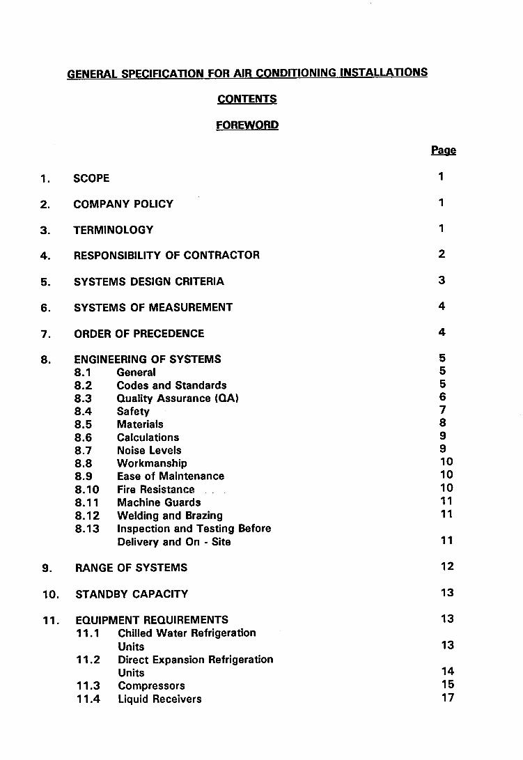
CONTENTS
FOREWORD
SCOPE
COMPANY POLICY
TERMINOLOGY
RESPONSIBILITY OF CONTRACTOR
SYSTEMS DESIGN CRITERIA
SYSTEMS OF MEASUREMENT
ORDER OF PRECEDENCE
ENGINEERING OF SYSTEMS 8.1 General 8.2 Codes and Standards 8.3 Quality Assurance (QA) 8.4 Safety 8.5 Materials 8.6 Calculations 8.7 Noise Levels 8.8 Workmanship 8.9 Ease of Maintenance 8.10 Fire Resistance 8.1 1 Machine Guards 8.12 Welding and Brazing 8.13 Inspection and Testing Before
Delivery and On - Site
RANGE OF SYSTEMS
STANDBY CAPACITY
EQUIPMENT REQUIREMENTS 1 1.1 Chilled Water Refrigeration
Units 11.2 Direct Expansion Refrigeration
Units 11.3 Compressors 11.4 Liquid Receivers
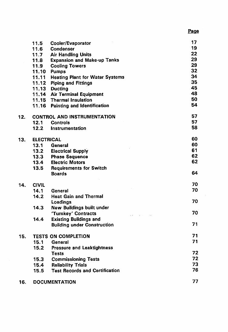
Cooler/Evaporator Condenser Air Handling Units Expansion and Make-up Tanks Cooling Towers Pumps Heating Plant for Water Systems Piping and Fittings Ducting Air Terminal Equipment Thermal Insulation Painting and Identification
12. CONTROL AND INSTRUMENTATION 12.1 Controls 12.2 Instrumentation
13. ELECTRICAL 13.1 General 13.2 Electrical Supply 13.3 Phase Sequence 13.4 Electric Motors 13.5 Requirements for Switch
Boards
14. CIVIL 14.1 General 14.2 Heat Gain and Thermal
Loadings 14.3 New Buildings built under
'Turnkey' Contracts 14.4 Existing Buildings and
Building under Construction
15. TESTS ON COMPLETION 15.1 General 1 5.2 Pressure and Leaktightness
Tests 15.3 Commissioning Tests 15.4 Reliability Trials 15.5 Test Records and Certification
16. DOCUMENTATION
17. MAINTENANCE TOOLS AND SPARES 17.1 Maintenance Tools and Test
Gear 17.2 Spares Holdings 17.3 Protection, Packing and
Marking
"A" - Quality Control System ASME Section Vlll - Division 1 Pressure Vessels
"B" - Quality Control System ASME Section IV - Heating Boilers
"C" - Codes and Standards - Abbreviation and Addresses of Publishing Organisations.
FOREWORD
The Company intends that the air conditioning system operating in both existing and new buildings shall be designed to be both reliable and economic in operation. In particular, it is desired that operational power losses should be minimal and plant correctly sized and rated for the required duty.
These objectives will be attained by:
1. Specifying higher standards for both design and quality of supplied plant.
2. Establishing more reasonable limits for the climatic conditions to be satisfied.
3. Improving or extending the heat transfer data specific to Kuwait conditions and forms of construction used.
4. Reducing the impressed heat load by improving the insulation standards of the containment structures.
This specification has been written to satisfy Items 1 and 2. Item 3 is considered to be the responsibility of others. Objective 4 will be achieved by means of the Civil Engineering Specifications issued by Engineering Group to cover specific installations.
Throughout this document, the words 'will', 'may', 'should', 'shall' and 'shall normally', have specific meanings as follows:
'Will' is normally used in connection with an action by the Company, rather than by a contractor or vendor.
'May' is used where a provision is completely discretionary.
- -- * . - - - 'Should' is used where a provision is advisory only.
'Shall' is used where a provision is mandatory.
'Shall Normally' is used where an element of choice will be permitted providing that an acceptable, technical justification can be made.
Note that discretionary or advisory requirements may be qualified by the Company in an accompanying technical specification relating to a particular installation.
ANYS E. RASHID G.S. Standards & Inspection Dept.

GENERAL SPECIFICATION
AIR CONDITIONING INSTALLATIONS
1. SCOPE
This specification has been prepared to offer general guidance on Company policy and requirements to be taken into account in the design, supply, installation and testing of air conditioning systems for Company installations. It is intended to be complementary to the Particular Technical Specification prepared to cover a specific installation and should be read in conjunction with that document together with the General Conditions of Contract for Engineering, Construction and Maintenance Contracts and such other contractual data that may be specifically issued.
2. COMPANY POLICY
It is Company policy to minimise unnecessary losses of energy in air conditioning units or systems. Air conditioning equipment offered to the Company shall be correctly matched to the anticipated cooling loads and provide efficient and economical operation. Plant offered shall be adequately proven for operation within the climatic conditions of Kuwait and evidence to this effect shall be provided. The equipment shall be designed and manufactured in accordance with sound engineering principles and must provide a high level of reliability. (See Quality Assurance Section 8.3.) The system must be rated for the prevailing climatic conditions in Kuwait and certified to this effect. The equipment supplied and installed will become the property of the Company once the contractual requirements have been met and the plant has been fovmaliy handed over.
3. TERMINOLOGY
In this standard the following expressions shall, unless the text indicates otherwise, have the following meanings.
(a) "Company" means the Kuwait Oil Company (K.S.C.) Permitted abbreviation KOC.
(b) Superintendent means the person appointed by the Company with the overall responsibility for ensuring that the works or services required are correctly completed. (As used in this Specification the word "Superintendent" is to be read as synonymous with Superintendent's Representative.)
(c) "Superintendent's Representative" means the person appointed by the Company of Superintendent to supervise the works required by the Contract, yet the materials involved and assess the adequacy of the standard of workmanship.
(d) "Contractor" means the firm or company responsible for the completion of all aspects of the works to be performed in accordance with the contract. The Contractor is normally accountable for any specific design work required and for the correct specification of equipment, materials, services, etc., to be provided by Vendors or other subcontractors.
(e) "Vendor" means the firm or agent that provides standard or proprietary items of plant or equipment, materials and fittings that are not individually designed for any particular application, but form part of a standardised range.
(f) "Particular Technical Specification" means the document prepared by Company Engineers which describes the detailed requirements for a specific air conditioning installation and defines the scope of the works to be carried out.
4. RESPONSIBILITY OF CONTRACTOR
4.1 The Contractor and/or Vendor shall be totally responsible for the operational effectiveness of the installation(s) and/or equipment(s) provided.
4.2 Regardless of the inspection and quality control activities of the Company, the responsibility for the overall control of quality rest with the Contractor and/or Vendor.
4.3 It is required that the Contractor shall critically examine the design and rating data included in the Particular Technical Specification. The Company will consider any suggestions submitted by the Contractor for alternatives or modifications that may improve the design or bring reductions in the cost of procurement or operation.
4.4 The Contractor shall become sufficiently conversant with the structural design and layout of existing or new buildings to enable the specification for the complete installation to be optimised and the heat gains or losses accurately assessed.
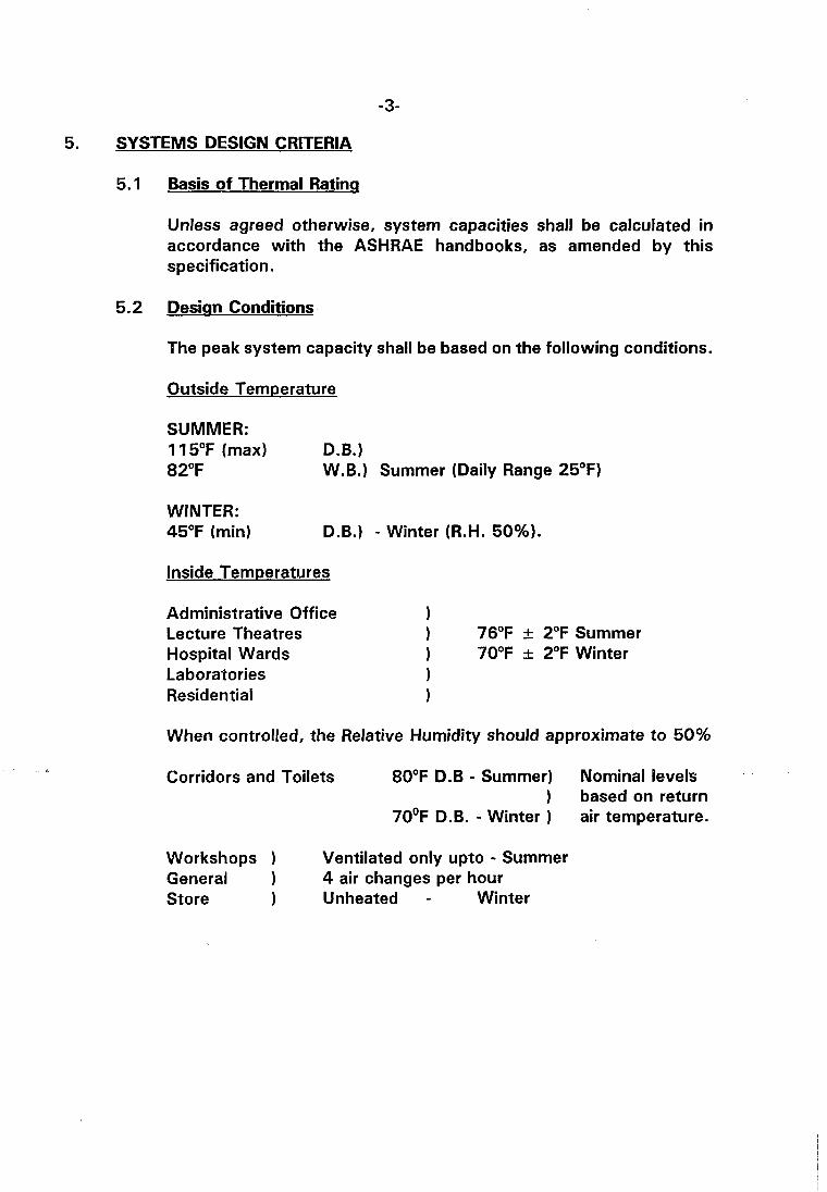
5. SYSTEMS DESIGN CRITERIA
5.1 Basis of Thermal Ratinq
Unless agreed otherwise, system capacities shall be calculated in accordance with the ASHRAE handbooks, as amended by this specification.
5.2 Design Conditions
The peak system capacity shall be based on the following conditions.
Outside Tem~erature
SUMMER: 1 15°F (max) D.B.) 82°F W.B.) Summer (Daily Range 25°F)
WINTER: 45°F (min) D.B.) - Winter (R.H. 50%).
Inside Temperatures
Administrative Office Lecture Theatres 1 76°F + 2°F Summer Hospital Wards 1 70°F k 2°F Winter Laboratories 1 Residential 1
When controlled, the Relative Humidity should approximate to 50%
Corridors and Toilets 80°F D.B - Summer) Nominal levels ) based on return
7 0 ' ~ D.B. - Winter ) air temperature.
Workshops 1 Ventilated only upto - Summer General 4 air changes per hour Store 1 Unheated - Winter

5.3 Ventilation Rates
Rates to be generally between 6 and 15 air changes per hour, dependant on air conditioning load, with a fresh air allowance of from 15 to 20 C.F.M. per person.
Toilet extract systems shall be designed to provide 10 to 12 air changes per hour of extract ventilation. An estimate shall be made of the air infiltration rate into the air conditioned areas or buildings. In situations in which the data for this estimate are not readily available a figure of one half an air change per hour may be assumed for tender submissions.
5.4 Air Conditioned Bundinas
It is appreciated that the static pressure within air conditioned buildings will vary from area in relation to the location and/or use of any particular room or zone.
However, unless required otherwise by the Particular Technical Specification, air conditioned buildings shall normally be designed to operate at a nominal, positive pressure of 0.2 in W.G.
6. SYSTEM OF MEASUREMENT
The Imperial System is preferred for all calculations carried out in accordance with the ASHRAE design procedures. The S.I. or Metric Systems may be used, if desired, but in this case, the Imperial equivalents of key design data must be given in parenthesis.
7. ORDER OF PRECEDENCE
In the event of any variance or disagreement between the various documents issued or referred to in relation to any particular contract, the Order of Precedence will be as follows:
First - The Particular Technical Specification. Second - This Standard Specification. Third - KOC General Specifications. Fourth - National or other standards or codes.

8. ENGINEERING OF SYSTEMS
8.1 General
This specification has been prepared to cover Air Conditioning units ranging upto several hundred tons capacity. It specifies the basic engineering requirements of both direct expansion and chilled water systems.
Primary equipment is common to all systems and includes pressurised piping vessels and components; heat interchangers of various types; air distribution systems: and environmental control units.
Accordingly this specification consists of a general section, common to all installations, together with specific sections covering Refrigeration Units; Air Handling Units; Heat Exchanger; Pressurised Vessels; Heating Boilers; associated Pipeworks; Ducting; Etc.
8.2 Codes and Standards
The plant supplied shall be designed, manufactured and installed in accordance with sound and proven engineering practices appropriate to the class of the equipment involved.
The edition current at the time of tendering shall be used.
The following codes are relevant to certain equipments and shall be applied whenever appropriate.
KOC General Specification for Civil Engineering, Building and Electrical Works.
--
KOC General Specification for Electrical Engineering in Industrial Plants.
ASME Boiler and Pressure Vessel Code - Section Vlll - Pressure Vessels - Division 1.
ASME Boiler and Pressure Vessel Code - Section IV - Heating Boilers.
ANSl B31-1 Power Piping.
ANSl B31-1 Refrigeration Piping.
TEMA - Standards of Tubular Exchanger Manufacturers Association.
ASHRAE Standards and Associated Codes (As listed in ASHRAE Handbooks).
I.P. Code of Safe Practice - Part 1 - Electrical.
API - RP 500A - Recommended Practice for Classifications of Areas for Electrical Installations in Petroleum Refineries.
Should alternative standards be used, then these should be identified in the tender return. In general the Company is prepared to accept American or British Standards. However, alternatives would be accepted provided it could be demonstrated that equivalent quality standards would be realised.
Qualitv Assurance (OA)
Equipment supplied is required to posses a high level of reliability and hence must be known good quality.
The Company will require assurance that the system overall and the individual components and sub-assemblies are designed, manufactured, installed and tested in accordance with a planned and coherent quality programme. It is of paramount importance that pressurised systems (including vessels and heating boilers), pumps, compressors circulating fans and control units are adequately covered.
In preparing submissions clarifying or defining quality policy due regard shall be given to the provisions and requirements of BS5750. Quality Systems.
Part 1 of this standard "Specification for Design, Manufacture and Installation" shall apply to the supply of the system overall and to any specific items or sub-assemblies of proprietary design (e.g pumps; compressors, etc.) or equipment based on a design code that is non- specific on detail (e.g ASME Section VIII; TEMA, etc.,)
Part 2 of this standard "Specification for Manufacture and Installation" shall apply to the supply of standardised components of defined form and duty (e.g pipe fittings; flanges; etc.)
Attention is drawn to the mandatory appendices in the ASME Pressure Vessel Code Section Vlll - Division 1 and Section IV on Quality Control Systems which are reproduced as Appendices A and B to this Specification. They may be used as a model for the QA requirements relating to all pressurised plant covered by the ASME
Codes and also for key, uncoded items.
Useful reference may also be made to the following standards:
BS 4891 - A Guide to Quality Assurance.
BS 51 79 - Guide to the Operation and Evaluation of Quality Assurance Systems.
Established safe practices shall be applied or incorporated in both the design and operation systems. In particular the provisions and recommendations of BS 4434 - Requirements for Refrigeration Safety and ANSIIASHRAE 15 - Safety Code for Mechanical Refrigeration shall be followed unless at variance with the stipulations of particular Company specifications.
Unless specified otherwise, all refrigerants used in direct cooling, air conditioning systems shall conform to BS 4434 Group 1 and shall be non-explosive, non-combustible, non-toxic and non-irritating. Concentrations arising from system leakage under fault conditions shall not exceed the margins of safety set out in Table 6 of BS 4434 unless authorised otherwise by the Superintendent. Attention is particularly drawn to the sections in BS 4434 covering Working and Test Pressures; Pressure Vessels and Refrigerant Piping and Fittings.
In the case of secondary systems, using Group 2 refrigerants, due regard should be given to relevant engineering standards set in the Institution of Refrigeration Code of Practice-Design and Construction of Systems using Ammonia as the Refrigerant.
. - ,
Consideration should also be given to the requirements and recommendations of the following standards.
UL 900 Safety for Air Filter Units UL 507 Safety Standards for Electric Fans UL 555 Safety Standards for Fire Dampers UL 499 Safety Standards for Electrical Heating Appliances.
Every effort should be made to locate air conditioning plant in safe areas. Plant that, or necessity, must be installed in hazardous areas, shall meet established, flameproof, safety requirements and be certified to this effect.
Accordingly, plant stipulated as "Flameproof" shall comply with either one of the following specifications.
i Certified flameproof for Zone 1 hazardous areas and Group IIA and llB Gases, enclosures to BS 4683; Part 2 or, certified flameproof for Division 1 hazardous areas as per Institute of Petroleum, Great Britain. Electrical Model Code of Safe Practice, Part 1.
ii) Certified flameproof for Division 1 Class 1 locations and group C and D Gases, as per American Petroleum lnstitute Recommended Practice APlRP 600 A.
All equipment for outdoor operation shall be suitable for the following conditions:
Maximum summer temperature 122°F Relative Humidity 100%
Minimum winter temperature 27°F Relative Humidity 100%
The following bare metal surface temperatures may be reached due to direct sunlight (Sun Temperature 185°F max.).
White body 145°F Black body 179°F.
8.5 Materials
Materials used in the construction of the plant shall be procured and manufactured to recognif ed standards. Detailed material lists shall be included in the operational manuals to be supplied. Mill test certificates shall be obtained for materials used for the construction of pressurised equipment designed to ASME or ANSI pressure vessel or piping codes.
Specific material requirements for particular equipment or plant are specified in the relevant sections.
Any materials which are considered to be of interior quality or which are not installed in accordance with the specification may be rejected by the Superintendent.
8.6 Calculations
The Contractor shall submit three sets of design calculations for review by Company engineers. The calculations must be annotated as checked and approved at the appropriate levels.
The application of design methods other than those described in the ASHRAE Handbook shall be justified.
Comprehensive calculations are required and shall cover coolinglheating load estimates, distribution pressure drops, pump and fan ratings; heat exchanger performance, etc.
Cooling system capacity shall be based on ASHRAE data as amended or extended by the information contained in this specification.
8.7 Noise Levels
The system(s) shall be designed to minimise the amount of noise that is transmitted to or generated in occupied, air conditioned areas. All moving components and associated equipment shall be selected and installed to function quietly without resonance.
Except where definite noise levels are specified, the Contractor shall be responsible for ensuring that the component parts of the installation operate at the correct noise level consistent with the use of the building or project. No discernible noise or vibration shall be transmitted from any part of the installation to the building structure.
Design levels for indoor noise shall be set generally in accordance with the tabulated data included in the Sound and Vibration Control section of the Systems Volume of the ASHRAE Handbook.
In particular, the following levels shall be achieved:
Area Sound Eauivalent Criteria dBA Level
Conference & Lecture Halls; Hospital Wards detached private homes; executive offices. NC 35 40
General Offices, apartment flats, corridors. NC 40 45
Industrial Kitchens, Workshop Stores
Sound level monitored by an approved sound level meter positioned three feet distant from the air supply and exhaust grills/louvres shall not exceed the stated dBA figures. The Contractor shall also submit to the Superintendent for his approval full details of the methods he intends to use to ensure silent running and freedom from vibration. The final decision on the achievement of the proper degree of silence and of the elimination of vibration in the completed installation shall rest with the Superintendent.
The Superintendent shall have full powers to reject any part of the installation which, in his opinion, is not properly erected or installed by reason of poor workmanship. Such parts shall be made good to the best accepted standards, entirely at the Contractor's expense.
The Contractor shall be responsible throughout the contract for ensuring that the trade, custom and local practice is followed in the employment of the appropriate grades of operatives.
The Contractor shall ensure that all craftsmen used are competent and qualified in their trade. Particular attention is drawn to the Welding details, and only welders with the necessary site experience and welding test certificates are to be employed. (See also Section 8.12)
Ease of Maintenance
The Contractor shall at all time give proper consideration to the future maintenance of the plant and shall include for such component parts as are provided by the manufacturer of equipment and plant for this purpose. Under this clause the Contractor shall include for suck items as cleaning and access ports on pressure vessels and heat exchanger, easy access to oiling and greasing points, low level drain plugs andlor cocks in all vessels, plant or pipework containing fluids or gases. This clause shall also cover the installation of equipment to give ease of subsequent removal of electric motors, thermostats, heat exchange batteries, or other equipment, and of any other item to which it may be reasonably anticipated that maintenance would apply.
Fire Resistance
All materials used in connection with or as part of the installation shall not be capable of spontaneous combustion, nor shall they suppo:~ combustion, hut should be self-extinguishing.
8.1 1 Machine Guards
Every rotating, reciprocating or moving part of compressors, pumps, fans and other machines shall be properly protected by manufacturer's standard or purpose made machine guards. All machine guards shall be manufactured from solid sheet metal or wire mesh or steel frame, all galvanised after manufacture and shall be so designed with hinges and/or removal sections to allow for maintenance and all necessary tachometer readings. In the design of purpose - made guards, due regard shall be given to the provisions of B.S. 5304 - Code of Practice for Safeguarding of Machinery.
8.1 2 Weldina and Brazing
a) The Contractor shall use only competent, skilled and qualified craftsmen for welding and brazing operations. The work shall be adequately supervised at all stages.
b) Welding and brazing procedures and welders or operatives shall be qualified in accordance with the ASME Pressure Vessel Code Section IX - Welding Qualifications or to such other standards that may be acceptable to the Superintendent of lnspection and Corrosion Division.
C) Fabrication standards shall meet the minimum levels set by the appropriate ASME or ANSI Code for all items of manufacture that fall within the scope of these codes.
d) The welding of structural steelwork shall be carried out generally in accordance with AWS Code D l .I - Structural Welding Code - Steels to BS5135 - Metal-arc welding of Carbon and Carbon Manganese Steels; or equivalents acceptable to the Superintendent of lnspection & Corrosion Division.
8.13 lns~ection and Testina before Delivenr and On - Site
a) The Contractor shall be responsible for all inspection and testing required by law, the contractual documents, appropriate codes and sound engineering practices of all equipment spare parts and materials prior to delivery for incorporating in the air conditioning system(s).
b) In a like manner, the Contractor shall be responsible for all the inspection and testing necessarily carried out on-site during and on completion of construction.
C) The Company shall have the right at all times, in co-ordination with the Contractor, to inspect or cause the inspection of, or witness the testing of any equipment, parts or materials prior to delivery or any part of the works during site construction and installation.
d) Inspection or witnessing by the Company or failure to inspect and witness, shall not be construed as acceptance of any part of the work nor as relieving the Contractor of the responsibility for any part of the work complying with the requirements of the relevant specification(s) and being from defects and capable of performing their respective functions.
9. RANGE OF SYSTEMS
It is Company policy to rationalize the range and diversity of air conditioning plant. Current requirements are satisfied by the use of systems that fall into either of the following two main classifications.
Currently KOC systems utilise Refrigerant 11; Refrigerant 12; Refrigerant 22, Refrigerant 500 and Ammonia. Whilst preference should be given to the use of this range of refrigerants, the Company is prepared to consider the use of alternatives providing that a sound economic and/or practical case can be made.
9.1 Chlled Water Refriqeration Units
These units may be further classified into two categories:
i Large, central, site-assembled units or modules upto and exceeding 500 tons (ref) capacity.
ii) Factory-assembled Package Units for capacities upto some 100 tons (ref).
9.2 Direct Ex~ansion Refri~eration Units
These units may be classified into three categories:
i Large, central units, air-cooled or water-cooled with open compressors having maximum capacities of some 75 tons (ref).
ii) Package Units, normally air-cooled, with semi-hermetic compressors having capacities of some 25 tons (ref).
iii) Small Package Units, air-cooled with hermetic compressors with capacities upto some 10 tons (ref).
9.3 Alternative Svstems
The Company is prepared to consider the supply of systems outside the general categories listed above providing that a good engineering and/or economic case can be made for their application in any particular circumstance.
Note (1) Ton refrigeration - A rate of heat extraction of 12000 BTU (8200kcal) per hour.
10. STANDBY CAPACITY
Consideration shall be given to the degree of stand-by capacity that may be reasonably and economically provided.
For small units (10 tons (ref)), serving individual dwelling houses, stand-by capacity will not normally be required. For large units, serving office accommodation, laboratories, etc, 60 to 70% of the full rated capacity shall be available at all times.
Unless agreed otherwise, the basis for the stand-by assessment shall be one major failure in any one air conditioning system i.e. 1 unit lost of 2 or 1 unit lost of 3.
Any buildings or ventilated areas requiring a 100% stand-by capacity will be identified in the Particular Technically Specification.
1 1. EQUIPMENT REQUIREMENTS
1 1 .I Chilled Water Refriaeration Units
These systems use water as a secondary refrigerant. The units may be factory assembled and wired or, in the case of larger systems, shipped in sections for field erection. The air-conditioned spaces may be cooled by piping chilled water to fanlcoil heat exchanger situated within those spaces and/or by ducted, cool air delivered from a central air handling unit to which the chilled water is supplied or combination of both.
The basic components include a compressor, liquid cooler (evaporator), condenser, compressor drive and control unit. A means of heating would normally be provided to cover winter operation.
1 1.2 Direct Ex~ansion Refriaeration Units
In these systems, cooling is normally performed directly by the primary refrigerant, although secondary refrigerants may be utilized, if required. In the direct system, cooling usually takes place within an Air Handling plant situated away from the condensing unit hence these systems employ field-fabricated and installed refrigerant piping.
The basic components are similar to those of the Chilled Water unit except that a dry expansion cooler replaces the liquid cooler and secondary heat exchanger equipment is rarely involved.
The similarity of the basic system components permits their common treatment in the sections that follow. Where significant differences are to be found these are stated.
11.3.1 General
Contemporary good practice shall be followed. Hermetic units shall be used in plant with capacities upto 10 tons, semi-hermetics on plant with capacities upto some 25 tons, and for the larger units open reciprocating, centrifugal, turbine or screw compressors shall be selected, as most appropriate to the service requirements and efficiency required.
Variations from these general classifications shall be declared and justified.
Compressor ratings shall be such as will ensure long, trouble free operation. The compressor(s) shall be tested and rated in accordance with the current edition of either of the following standards:
ASHRAE 23 - Methods of Testing for Rating Positive Displacement Refrigerant Compressors.
BS 31 22 - Rating and Testing of Refrigeration
- .- s Compressors.
The form and results of these tests shall be reported. Details should advisedly be submitted of any long duration or type tests that may have been carried out on a particular compressor model or series.
Desinn
The compressor design shall accord with proven good practice and the material build be appropriate for the prescribed operating conditions and refrigerant.
Due regard shall be given to the relevance of the following publications:
ARI 510 - Ammon ia Compressors and Compressor Units.
API 520 - Positive Displacement Refrigeration Compressors and Condensing Units.
ANSI B 143.1 - Sealed (Hermetic Type) Motor- Compressors for Refrigeration Service.
The Codes and/or Standards applicable to any particular design of compressor shall be stated.
Reciprocating compressors shall be fitted with an electrical resistance, crankcase heater of sufficient capacity to keep the crankcase oil free from contamination by liquid refrigerant during periods when the compressors are non-operational. The heater shall be controlled automatically to follow the compressor loading cycle.
Control and Safety
Factory built, wired and tested controls panels are preferred and shall be supplied whenever technically possible. The paneb) shall contain all the necessary controls for efficient and safe operation of the compressor unit(s). For multi-cylinder, reciprocating compressors the preferred method of capacity control is by the use of solenoid suction valve lifters operating under thermostatic control.
- . - --- - In the case of larger systems in which it is practicable to employ a number of individually driven compressor units, the preferred method of capacity control is by selective unit switching.
In principle, any significant departure from the normal range of operating conditions should actuate a warning or i f necessary for safety reasons, initiate a compressor trip. The Control modes and safety instrumentation shall be fully detailed in the tender submission.
1 1.4 Liauid Receivers
Packaged chillers of the Direct Expansion type shall be supplied with a Liquid Receiver complete with all accessories. Receivers shall have sufficient capacity for holding the system's full charge of liquid refrigerant.
All receivers shall be ASME Code Stamped or approved by a reputable Inspection Authority (e.g. Lloyds). They must be suitable for operation at the specified working pressure and must have satisfactorily passed an hydro-static pressure test at not less than 1 % times the design pressure.
Due regard shall be given to the following publications:
ARI 495 - Refrigerant Liquid Receivers
UL 207 - Refrigerant Containing Components and Accessories, Non-electrical.
This section is limited to the consideration of the shell and tube class of cooler such as would be used in a dry expansion system or to the evaporative type of chiller as employed in flooded systems. In the dry expansion chiller, the refrigerant flows through the tubes and the liquid to be cooled through the shell. In the case of flooded systems, the refrigerant is contained in the shell and the fluid to be cooled in the tubes. For smaller plants, the shell may also act as liquid receiver.
11.5.2 Rating
The cooler rating shall be ascertained in accordance with ASHRAE Standard 24 - Methods of Testing for Rating Liquid Coolers.
The rating thus obtained shall be stated.
Desian
The mechanical design of the cooler shall be based on the standards published by the Tubular Exchanger Manufacturers Association (TEMA). Any deviations from these standards shall be declared and justified. The class of exchanger offered shall be stated.
Reference shall also be made to ARI 480- Refrigerant-Cooled Liquid Coolers, remote Type, as appropriate.
Both shell and tubes circuits of the cooler I evaporator shall be tested hydrostatically to a pressure of not less than 15 times the design pressure. Pressure drops across the unit (including water boxes) shall not normally exceed 10 lbflin2.
Isolating valves shall be provided on all lines. Temperature and pressure monitoring points shall be provided on the entry and exit lines for the fluid to be cooled. Refrigerant flow rates shall be suitably metered and temperature (s) monitored. Provision for pressure relief shall be made in accordance with the relevant code.
Flooded chillers shall be fitted with a suitable demister to prevent carry over of liquid refrigerant. Consideration shall be given for their need in dry expansion systems to protect the compressor from liquid carry over under fault conditions.
Liquid refrigerant lines shall be provided with a drier-strainer unit, complete with isolating valves and by-pass, together with a sight glass and moisture indicator.
A liquid suction heat exchanger shall normally be included in the circuit.
Materials of construction shall be selected to give a long service life and must be compatible with primary and secondary refrigerants.
Particular care is required in the selection of materials for brine chillers. Preference shall be given to the use of cupro-nickel grades for tubes, tube - plates and division plates.
Ferrous tubes are not acceptable in other than ammonialwater systems where a corrosion allowance of not less than 0.060 in shall be provided. The need for cathodic protection of the water boxes shall be examined.
The guidance given in the ASHRAE Handbooks shall receive consideration. Under no circumstances shall copper, copper alloys and brass be utilised in ammonia systems.
Full details of the material build to be supplied shall be provided. Any corrosion allowances allocated shall be listed.
1 1.6 Condensers
11.6.1 Water Cooled
Shell and Tube condensers are preferred. Double-Tube and Shell and Coil condensers are acceptable for the smaller, package units providing that adequate arrangements may be made for the removal of any fouling from the heat transfer surfaces.
ii) Ratinq
The rating of the condenser shall be specified and the basis for such rating declared.

Due regard shall be given to the provisions of the following standard.
ASHRAE 22 - Method of Testing for Rating Water Cooled Refrigerant Condensers.
iii) Desian
The mechanical design of tube and shell condenser units shall be based on the standards published by the Tubular Exchanger Manufacturers Association (TEMA).
Double-Tube units shall be designed in accordance with the ASME Pressure Vessel Code Section VIII, Division 1 or to ANSI B3 1 -3-Chemical Plant and Petroleum Refinery Piping.
Both shell and tube circuits shall be hydraulically tested to a pressure of not less than 1 % times the design pressure. Any deviations from the above standards shall be declared and justified. In the case of TEMA designs, the class of exchanger offered shall be stated.
The following standard is also cited and should be followed where relevant:
P - - ARI 450 - Water-cooled Refrigerant Condensers, Remote Type.
iv) Materials
The material requirements shall be as specified in sub-section 11.5.4. The use of ferrous tubing in sea water or brackish water cooled units is not acceptable (other than in ammonia systems).
Air Cooled
i) General
Air-cooled condensers shall be of the forced air draft type, capable of meeting the maximum load when the ambient temperature is not less than 115°F and having a gross heat rejection not less than the evaporator capacity plus the heat added to the refrigerant by the compressor(s).
Fans may be of the axial flow or centrifugal type, whichever is most appropriate to the installation. They shall be statically and dynamically balanced for quiet operation.
Unless otherwise specified, they shall be provided with solid steel shafts, sealed life- lubricated ball bearings, and driven by resiliently mounted, weather-proofed motors with built-in thermal overload protection. Direct drive or belt units are equally acceptable.
In multi-fan units the preferred method of heat rejection control shall be by sequential cycling of the fads) delivering to cooler sub-sections.
The rating of the condenser shall be specified and the basis for such rating declared.
Due regard shall be given to the following standard, as appropriate:
ASHRAE 20 - Method of Testing for R a t i n g R e m o t e Mechanical - Draft Air Cooled Ref r igeran t Compressors.
iii) Desiqn
Due regard shall be given to the provisions of ARI 460 - Remote Mechanical Draft, Air- Cooled Refrigerant Condensers, where appropriate.
The condenser design shall be such as will minimise the system refrigerant charge volume. The use of enhanced surface heat transfer tubing of a proven design is acceptable to the Company. The coils shall be of seamless copper tubing unless other considerations over-ride. Preference will be given to copper finned tubes, but aluminium fins are acceptable.
Cabinets shall be fabricated from heavy- gauge sheet steel treated to resist corrosion in a manner approved by the Company. The Condensers shall be fully weather-proofed throughout and shall require no additional protection from adverse weather conditions. They shall incorporate removable panels to provide access for inspection and repair.
11.7 Air Handlina Units
General
- . .' -*- - -- Chilled water and most direct expansion systems require Air Handling Units to be positioned within the building to be air conditioned.
Whenever practicable, this equipment shall be fabricated as a self-contained package unit.
The Air Handling Units shall be complete with all accessories and have the capacities and ratings required by the Particular Technical Specification.
Due regard shall be given to any relevant provisions contained in ARI 430 - Central Station Air Handling Units.
Circulatinq Fan
The circulating fan shall be designed to achieve a high operational efficiency utilising flow velocities that will ensure quiet running without resonance. The fan and drive unit shall be so rated as to provide the specified flowrates when the pressure drop across any filters in the system has reached the design maximum.
Vee belt drives shall be applied in matched sets and used in balanced sheaves to minimize vibration and ensure a long service life. Belt guards or coupling guard, it direct drive is used, shall be fitted.
Chilled and Hot Water Coils
The coils shall utilise seamless copper tubing fitted with copper or aluminium fins of proven design. Coil air face velocities shall not exceed 5OOftlmin. (2.5mls). Coil water velocities shall be such as will ensure quiet operation. Design utilising velocities greater than 4ft.ls (1.25mls) shall be declared and justified.
Unless specified otherwise, control shall normally be via a three-way, motorized valve actuated by a thermostatic controller situated in the return air chamber.
Principal -W'k* be supplied complete with pressure gauges and thermometers at inlets and outlets. Unless agreed otherwise, they shall be designed for a minimum working pressure of 200 lbflin2. ( * Those other than room fanlcoil units.)
Due regard shall be given to the provisions of ARI 410 - Forced Circulation Air-Cooling and Air- Heating Coils. Coil ratings shall be determined in accordance with ASHRAE 33-Methods of Testing for Rating Forced Circulation, Air-Cooling and Air- Heating Coils.
Direct Ex~ansion Coolina Coils
Air cooling coils of the direct expansion type shall be made of seamless copper with copper or aluminium fins of proven design mechanically bonded to the tubes. They shall be either of the dry or flooded type as required by the Particular Technical Specification . Coils shall be supplied complete with isolating valves, expansion or float valves (depending on the evaporator type), drain pans with drain connections on both sides and shall be of such dimensions that the face velocity does not exceed 500ftlmin (2.5mls). Drain pans shall be insulated against external condensation. Casings of the coils shall be of galvanised steel construction of adequate strength.
Due regard shall be given to the provisions of ARI - 410 Forced Circulation Air-Cooling and Air- Heating Coils. Coil ratings shall be determined in accordance with ASHRAE 33-Methods of Testing for Rating Forced Circulation, Air-Cooling and Air- Heating Coils.
11.7.5 Air Filtration
i 1 General
The dusty climate of Kuwait imposes severe conditions on tire design and operation of air filtration systems. The Company is prepared to accept any proven filtration system providing that it can achieve the prescribed efficiency level and is economical and reliable in operation.
All systems shall be designed to contend with dust storm conditions without significant "choking".
The dust holding capacity of the system(~) shall be such as will ensure an adequate period of operation under normal atmospheric conditions. The Contractor is required to state the anticipated maintenance periods for all elements within the system(s) offered in relation to an identified test dust.
The pressure drop across the filter shall be appropriate to the class of filter unit employed and shall not exceed 2 in. W.G. when loaded to its maximum recommended dust capacity.
All major systems shall incorporate means for the local indication of the pressure drop across the filter bank(s1.
Due regard shall be given in the design of the system to the provisions and recommendations of ANSIIUL 900 - Safety Standard for Air Filter Units.
ii) Svstem Efficiencies
The efficiency of the filtration units may be ascertained in accordance with either of the following standards.
ASHRAE Standard 52 - Methods of Testing Air Cleaning Devices Used in General ---- -- Ventilation for Removing Particulate Matter.
BS 2831 - Methods of Test for Air Filters used in Air Conditioning and General Ventilation.
The method used shall be declared.
The following minimum standards shall be achieved unless required otherwise by the Particular Technical Specification.
Normal Level
The normal level of efficiency required for off ice accommodation training centres, stores, workshops and domestic dwellings shall be:
a) Not less than 80% as measured by the ASHRAE Weight Arrestance Test (or equivalent)
Not less than 80% as measured by the ASHRAE Dust Spot Test (or equivalent)
Whichever test is most appropriate t o the filter system under consideration.
Hiah Level
The high level efficiency required for computer buildings, control rooms, instrument laboratories, hospital wards or to provide pre-filtration for ultra high efficiency systems shall be:-
Not less than 60% as measured by the 4 ...- -- .*- ASHRAE Dust Spot Test (or equivalent)
iii) Ultra Hiah Efficiencv Svstems and Chemical Absor~tion Units.
The specification of ultra high efficiency systems (such as required for hospital surgeries, etc.) and chemical absorption units necessary to protect sensitive equipment from gaseous contaminants are considered outside the scope of this general specification. Such systems, when required, will be specified in the Particular Technical Specification .
iv) Prefiltration of Fresh Air Intake
The intake system layout shall be such as will minimise the quantity of sand drawn in under dust storm conditions. Due attention shall be given therefore to the position, height, orientation and air velocities at entry points.
In major installations, having intakes of 2000 CFM (3400m3/hr) or greater, sand traps of the "laminar" flow or labyrinth type shall be designed into the intake system.
The air flow in "laminarn designs shall not exceed Gftlsec in the fall-out zone and the flow passage shall be smooth and unbroken in order to minimise local turbulence. Traps shall be provided with suitably sealed access hatches to facilitate clean-out.
Compact, cyclonic prefilters are an acceptable alternative to sand-traps providing that the induced air velocities are not such as will increase significantly the quantity of "fines" supplied to the main filter systemb).
11.7.6 Electric Duct Heaters - -C-- i- Y
The Air Handling Unit's shall be provided with electrical heaters when called for in the Particular Technical Specification. Any heater so specified shall be designed to operate from a single or three phase supply whichever is most appropriate. The heaters shall normally be arranged to provide step control via a multi-stage thermostatic system in such a manner as will maintain balanced loads across the phases.
The heater elements shall be of the finned sheathed mineral insulated type. Preference should be given to the use of 80120 Nickel Chromium resistance wire centered in a copper tube by means of compressed magnesium oxide. The finning shall be tinned copper or stainless steel section bonded to the sheath. The Company however is prepared to consider alternative designs of heater providing that they are of proven serviceability and offer equivalent safety standards.
All connections to the ends of the elements shall be screw terminal type and the inter-connecting wiring between the element shall be in heat resistant material.
The heaters shall be conservatively rated to give a long trouble free service life. Under normal circumstances the velocity of airflow through the electric heater batteries shall not exceed 1200 ftlmin. (6 MIS) nor the pressure drop exceed 0.1 in H,O ( 2 5 ~ 1 m ~ ) . Considerably lower velocity limits may be necessary however in certain zones to ensure that noise level restrictions are not exceeded. The heat flux (continuous rating) shall not exceed 4800 (BTuI~~~) ( 1 . 2 ~ 1 ~ ~ w l m ~ ) Operation at levels above those specified shall be declared and justified.
Each heater or heater section shall be protected with a thermal cutout switch set twhit-the- surface temperature of the elements to 212" OF (1 00°C).
A suitable, air-flow switch, preferably of the "paddle" type, shall be installed to cut off the power supply in the case of air flow failure.
An automatic cut-out shall also be provided to trip the heater supply in the event of power failure to the air handling unit motorb).
Control and Safety
A manually operated summerlwinter changeover switch shall be provided for each self-contained unit.
Provision shall be made for the unit to be shutdown in case of fire via a smoke detector located in the return airduct.
1 1.8 Ex~ansion and make-UQ Tanks
Expansion and Make-up Tanks shall be of adequate capacity and correctly located. Construction shall be generally in accordance with BS 417 Galvanised Mild Steel Cisterns and Covers, Tanks and Cylinders.
Suitable provision shall be made for the ready inspection of the interior.
Fibreglass tanks are equally acceptable providing that the design offered meets the approval of the Superintendent.
1 ti9 C o o i a Towers
General
No restrictions are placed on the cooling tower designs that the Company is prepared to consider. It is required, however, that the design offered shall operate economically and the material build be such as to permit long and trouble free service. However, unless technical considerations dictate otherwise, preference should be given to the induced-draught type.
Design shall be based on a Wet Bulb temperature of 80°F (summer conditions). Due regard shall be given to the recommendations of NFPA Standard 214 - Water Cooling Towers, in so far as they are appropriate.
Cooling towers shall be designed to withstand the wind pressures tabulated below over their full projected area and on supported equipment.
Tower Heiqht (Ft) Desian Wind Pressure (lbs1ft21
Less than 30 30 to 49 50 to 99
The design overall should seek to minimise blow- down to acceptable levels (preferably below 2 galslhourlton of the circulation rate). Drift eliminators shall be provided such that drift loss shall not exceed 0.002 of the total water circulation rate.
The towers shall be tested and performance evaluated in accordance with either of the following codes:
ASME PTC 23 - Atmospheric Water Cooling Equipment Test Code.
CTI-ATC-105 - Acceptance Test Code for - . .---- rCI --.- Water Cooling Towers:
Mechanical Draft, Natural Draft Fan Assisted Types and Evaluation of Results.
The code selected for application shall be stated. Calculations and performance curves shall be submitted.
The material build for the towers shall be such as will provide at least ten years service before major structural maintenance andlor total replacement of the internals become necessary.
Preference shall be given to the use of proven materials and finishes. Evidence of their suitability shall be provided.
Water Treatment
Treated water may be supplied from an existing Company source, alternatively, the supply may be made the responsibility of the Contractor. The responsibilities for the provision of water treatment systems will be defined in the Particular Technical Specification.
The coolant will be either sea-water containing upto 44,000 ppm of total dissolved solids (TDS) or brackish water containing upto 5000 ppm (TDS) .
The following notes are provided for guidance. Continuous chlorine injection is required to control bacteria and algae levels and concentrations of from 0.5 to 1.0 ppm are used. The chlorine level in water delivered to cooling towers of wooden construction should not exceed 0.5 ppm. Provision is also necessary for the periodic injection of selected bactericides in the form of "shock" treatments. Growth rates are reduced if sumps and catchment areas are protected from direct sunlight.
Attention should be given to the need to minimise the adverse effects on -pump-war and heat transfer flux resulting from the ingress of unacceptable levels of particulate matter into pumped circuits under dust storm conditions. Consideration should be given to providing an adequate settling zone upstream of the pump sump, alternatively, a non-choking filtration device, such as a centrifuge, may be installed in the delivery line.
The water pH and TDS levels must be controlled to minimise corrosion and scaling. Provision for the injection of suitable additives is necessary.
Particular attention must be paid to the scaling characteristics of the system. Fouling factors of not less than 0.002 should be used in design for both copper alloys and austenitic stainless steel tubed condensers. Tube water velocities should not be less than 3 fps if fouling is to be minimised. The maximum permissible velocity is set by the class of material used.
Provision for the removal of any scale shall be made by acid dosing treatments to be carried out with the unit "on-line" or shut-down, whichever procedure is shown to be most economic in any particular application. Adequate corrosion allowances shall be allocated to cover descaling operations.
The Contractor shall submit a detailed specification of his proposals for a suitable water treatment system for the consideration of Company Engineers. All materials shall be identified and corrosion allowances defined.
11.10.1 General
Split casing, centrifugal pumps shall be used, whenever practicable, for chilled and hot water, brine, brackish and sea water systems.
The pumps shall be designed, rated, installed an&-- - -- -- tested in accordance with the Standards of the Hydraulic Institute. The performance and efficiency of the pump may, if desired, be assessed in accordance with BS 599 - Methods of Testing Pumps. The application of alternative standards shall be declared.
All pumps shall be continuously rated and suitable for parallel operation. Pump speeds shall not exceed 1500 rpm. When pumps are insulated, vent cocks shall be positioned outside the insulation.
Casing
Impeller
Shaft
Shaft Sleeves
Test certificates and performance curves shall be submitted.
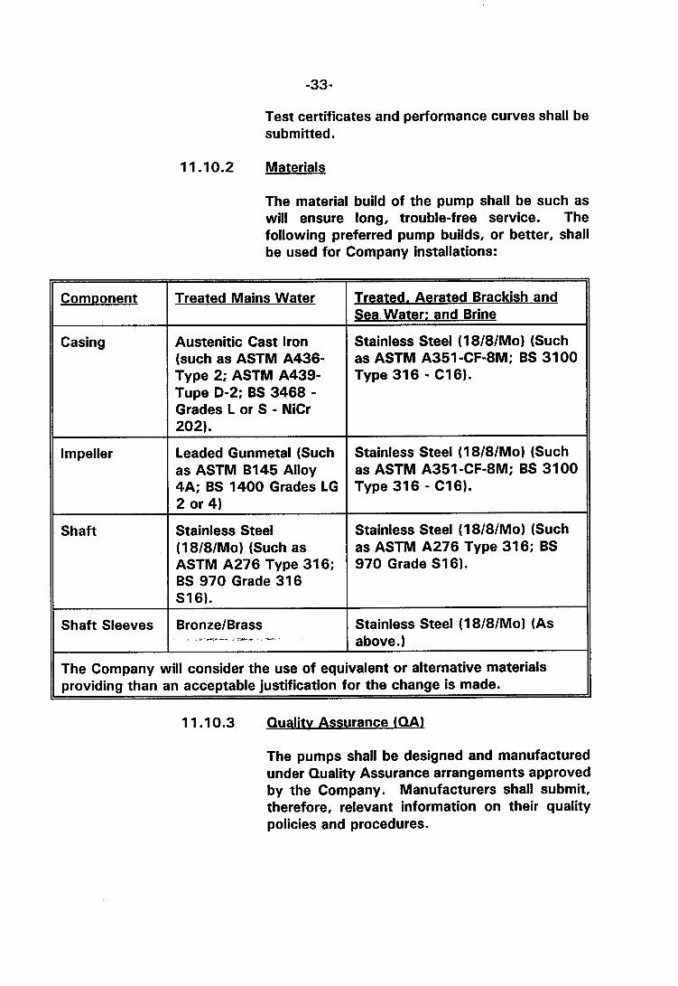
1 1 .10.2 Materials
The material build of the pump shall be such as will ensure long, trouble-free service. The following preferred pump builds, or better, shall be used for Company installations:
Treated Mains Water
Austenitic Cast Iron (such as ASTM A436- Type 2; ASTM A439- Tupe D-2; BS 3468 - Grades L or S - NiCr 202).
Leaded Gunmetal (Such as ASTM B145 Alloy 4A; BS 1400 Grades LG 2 or 4)
Treated, Aerated Brackish and Sea Water: and Brine
Stainless Steel (1 8181Mo) (Such as ASTM A351 -CF-8M; BS 31 00 Type 316 - C16).
Stainless Steel (1 8181Mo) (Such as ASTM A351-CF-8M; BS 3100 Type 316 - C16).
Stainless Steel (18181Mo) (Such as ASTM A276 Type 31 6; BS 970 Grade 31 6 S16).
Stainless Steel (18181Mo) (Such as ASTM A276 Type 31 6; BS 970 Grade S16).
The Company will consider the use of equivalent or alternative materials
BronzeIBrass _ . -r- -- *-
providing than an acceptable justification for the change is made.
Stainless Steel (1 8181Mo) (As above.)
1 1 .I 0.3 Qualitv Assurance (QAL
The pumps shall be designed and manufactured under Quality Assurance arrangements approved by the Company. Manufacturers shall submit, therefore, relevant information on their quality policies and procedures.
Heatinq Plant for Water Svstems
11 . I 1 . I General
Unless required otherwise in the Particular Technical Specification, the Contractor may supply water heating systems operated on fuel gas, oil steam or electricity, whichever source is most appropriate and economic for the application under consideration.
Whichever heat source is used, the installation shall be designed, constructed and tested in accordance with internationally recognized codes and standards. Such standards that are applied shall be reported.
The Contractor shall supply and install all necessary and required electrical equipment, switchgear, cables, wiring, control panel, etc., associated with the heating system, complete with all other standard accessories and controls as required for proper functioning of the plant.
1 1.1 1.2 Water Boiler
The pressurised shell shall be designed and manufactured in accordance with the appropriate section of the following national codes:
ASME Boiler and Pressure Vessel Code, Section IV - Heating Br~ile~s. - .
BS 855 - Welded Steel Boilers for Central Heating and Indirect Hot Water Supply.
BS 2790 - Shell Boilers of Welded Construction Part 1 - Class I Welded Construction Part 2 - Class II and Class Ill Welded Construction
Irrespective of the Code applied, each boiler shall be inspected by an Authorized Inspector or Inspection Authority, acceptable to the Company, and certified to this effect.
1 1 .I 1.3 Ancilliarv Fittinqs
Each boiler shall be complete with all ancilliary equipment necessary for its safe and economic operation. Each unit shall be provided with flanged inlet and outlet water connections and shall include suitable provision for drainage.
The provision of safety valves, valves, gauges and fittings shall be generally in accordance with BS-759-Valves, Gauges and other Safety Fittings for application to Boilers and to Piping Installations for and in connection with Boilers.
1 1.1 1.4 Control and Control Panel
The preferred Boiler Control Panel is the floor mounted, cubicle type, totally enclosed and dust- proof. Each Control Panel shall contain the mains isolator, interlocked with the door. The units shall be factory wired with PVC cables.
The Water Heater shall be interlocked with the hot water circulating pumps so that the heater remains inoperative unless the pumps are working. In addition the Chiller and Boiler shall be interlocked so that they cannot be operated together. The automatic control system shall meet or exceed the minimum recommendations given in Sections Five and Seven of BS855 and Section Five of BS759, whichever is most appropriate. - .-* -- --
Pi~inta and Fiintas
11.12.1 General
The Company is, in general, prepared to accept piping systems designed, fabricated and installed in accordance with the following codes:
Field of Ae~lication ANSI B31-1 - Power Piping All circuits other
than Refrigerants
ANSI B31-2 - Fuel Gas Piping Fuel Gas Systems
ANSI B31-3 - Chemical Plant All circuits and Petroleum Refinery Piping
ANSl B31-5 - Refrigeration Piping Refrigerant and brine circuits
BSICP 3009 - Thermally Insulated Underground Piping Systems.
Such exceptions as are required are defined in the Particular Technical Specification or this specification.
1 1 .I 2.2 S~ecif ic Desian and Test Reauirements for Pipinq Svstems Other than Refriaerant Svstems
i 1 Unions and Flanaes
Unions or flanges shall be fitted on both sides of each process unit and main circuit valves. Flanges shall be used on all lines 3 inches and greater in diameter. The number of unions or flanges used in any particular run shall be minimised.
ii) Valves
The valve build and design shall be proven for its given service and evidence to this effect provided, if requested Valves of 2% inch bore and over shall be flanged. --m ,-.. I Preference shall be given to valves with bolted body to bonnet connections incorporating where appropriate rising stems. All valves supplied shall be tested to the standards required in either of the
~ I
following specifications and certified to this effect.
API-STD 598 Valve lnspection and Test.
BS5146 - lnspection and Test of Steel Valves for the Petroleum. Petrochemical and Allied Industries.

The Company is prepared to consider the use of test specifications other than the above provided that their application will result in equivalent or better quality standards being achieved.
Valves shall be procured at all times from manufacturers applying viable quality assurance programmes.
iii) Pi~inq
Piping systems shall be designed on the basis of a minimum design life of 20 years. Materials of adequate strength, suitable for the particular corrosion environment shall be used. The anticipated corrosion rate in all primary circuits shall be stated. The actual materials of construction shall be precisely defined.
Water velocities in flow lines shall not exceed Gftls (1.8mls), unless specifically agreed.
Straight hot water runs greater than 32 feet (10m) in length shall have provision for expansion.
The Company is prepared to accept the minimum pressure test requirements of the ANSl Piping codes with the exception of ANSl B31-5-Refrigeration Piping (See following section).
All circuits shall be submitted to a pneumatic leaktightness test at 1 .I times the maximum operating pressure. The pressure shall be held for not less than 30 minutes. A "bubble" test of all joints, welds, etc., shall be reveal no observable leakage from the system.
iv) Materials
Unless otherwise specified, hot water piping and chilled water piping shall be seamless, standard weight, black steel to ASTM schedule 40, or BS 1387 Medium Class screwed or welded as required.
Condenser water piping used with fresh water shall be seamless, standard weight, galvanized steel to ASTM schedule 40, or BS 1387 Medium Class.
Drain piping and city water piping inside buildings shall be galvanized standard weight, screwed, piping to ASTM schedule 40 or BS 1387 Medium Class.
Fuel oil piping shall be screwed, seamless, black steel or soft copper as required by the Particular Technical Specification. Galvanized piping shall not be used for fuel services.
Materials other than those specified above may be accepted by the Company providing that it can be shown that the alternative(s) offered will give equivalent or superior service.
V) P i ~ e Sleeves
Where pipes pass through walls floors, etc., pipe sleeves shall be provided. The sleeve shall be sized to allow free movement of the pipe, plus insulation, where fitted. The nominal radial clearance provided shall be not less than 5116 inch. Sleeves shall protrude not less than 111 6 inch nor more than 118 inch.
vi) Pioe Suooorts and Hanaers
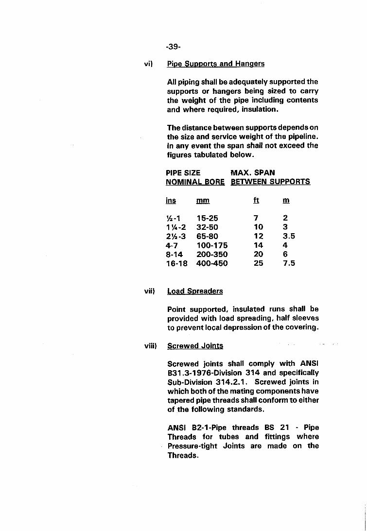
All piping shall be adequately supported the supports or hangers being sized to carry the weight of the pipe including contents and where required, insulation.
The distance between supports depends on the size and service weight of the pipeline. In any event the span shall not exceed the figures tabulated below.
PIPE SIZE MAX. SPAN NOMINAL BORE BETWEEN SUPPORTS
ins - - mm - f t m -
vii) Load Soreaders
Point supported, insulated runs shall be provided with load spreading, half sleeves to prevent local depression of the covering.
viii) Screwed Joints
Screwed joints shall comply with ANSl B31.3-1976-Division 31 4 and specifically Sub-Division 314.2.1 . Screwed joints in which both of the mating components have tapered pipe threads shall conform to either of the following standards.
ANSl B2-I-Pipe threads BS 21 - Pipe Threads for tubes and fittings where Pressure-tight Joints are made on the Threads.
ix) Strainers
All primary circulating pumps operating in closed systems, i.e. those not-subject to entry by airborne sand, shall be protected by suitable strainers. Strainer basket screens shall be correctly sized for the service conditions. The basket shall be readily removable from the body for cleaning. A by-pass shall be fitted together with the necessary isolating valves. A blow-off point for sediment removal shall be provided. Duplex - type strainers shall normally be installed in chilled water or brine circuits and condenser water systems.
The need for the fitment of strainers in "open" circuits as a back-up to sludge traps or centrifuges shall receive consideration.
S~ecif ic Desian and Test Reauirements for Refriaeration P i~ ina Svstems
Piping systems shall be designed on the basis of a minimum design life of 20 years. Materials of adequate strength proven for the particular corrosion environment(s) to be encountered shall be used. The anticipated corrosion rate(s) in all circuits shall be stated and the actual materials of construction precisely defined. Design stresses shall not exceed the levels specified in ANSI B31-3 OR B31-5. Where differences in permitted stress level occur between these standards the most conservative figure shall be used.
Good and proven engineering practices shall be followed. The requirements included under 1 1.12.2 shall be followed in so far as they are appropriate to refrigerant systems. In particular sub-sections (v) Pipe Sleeves; (iv) Pipe Supports (vii) Load Spreaders and (ix) Strainers shall apply.
Piping systems shall be installed to ensure proper liquid feed to the evaporators and continuous automatic return of oil to the compressors. Oil traps shall be provided where necessary in vertical lines.
The Company is not prepared to accept the minimum pressure test requirements as specified in ANSI B31-5-Refrigerant Piping. For Group I refrigerant circuits, the minimum test pressure shall be 125 x design pressure or relief valve setting whichever is greater, i f a gaseous medium is used. In the event that hydraulic tests are permissible this ratio shall be increased to 1.5.
The leaktightness test specified in the last paragraph of I I 12.2 (iii) shall apply to Group I refrigerant circuits.
Refrigerant circuits shall be supplied with
- all necessary fittings, including thermal expansiori valves or float valves (depending on the evaporator type): Liquid sight glasses moisture indicators, (preferably combined with sight-glass): filter driers; liquid line solenoid valves pressure regulators and high-low pressure controls.
ii) Pi~ework Joints
Unless specified otherwise in the Particular Technical Specification, the Company is prepared to accept the use of the jointing methods permitted in Chapter V of ANSl B31-5. Any or all of the following joints may be incorporated:
a) Welded b) Brazed C) Soldered (Preference should be given
to the use of recessed solder joint fittings)
d) Flare type e) Ferrule Bite type *' only permitted
with heavy wall tubing' f) Compression type *
* Acceptable on Group 1 circuits only unless authorised otherwise by the Superintendent. For guidance on joint designs suitable for ammonia systems (Group 2) See Institute of Refrigerant Code of Practice - Design and Construction of Systems using Ammonia as the Refrigerant.
iii) Materials
Unless specified otherwise in the Particular Technical Specification the Company is prepared to accept the use of materials listed on Table 502 B.l of ANSl B31.5. Materials other than those listed may be offered providing acceptable evidence is available of their serviceability under the given conditions.
Preference shall be given to the use of copper or copper alloy tubing in those systems in which these materials are compatible both with the refrigerant and working environment. Copper tubing supplied shall comply with, or be effectively equivalent to the following specifications:
ASTM B88 - Seamless Copper Water Tube
ASTM B280 - Seamless Copper Tube For Air Conditioning and Refrigeration Field Service
BS 2871 - Copper and Copper Alloy Tubes
The materials shall be used with due regard to the minimum requirements set out in ANSIIASHRAE 15 - Safety Code for Mechanical Refrigeration. In general, Type I tube may be used for general plumbing for normal service where only mildly corrosive conditions are encountered. Type K tube should be used for underground services and for general plumbing in systems liable to significant corrosion. In exposed locations hard temper copper generally should be used.
Annealed tube may be used with solder- type and flared fittings. Compression fitting may be used on annealed tubing upto a limiting nominal size of W inch. Drawn temper tubing may be used with solder-type fittings and is required for certain types of compression fittings or mechanical joints.
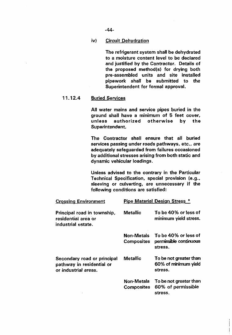
iv) Circuit Dehydration
The refrigerant system shall be dehydrated to a moisture content level to be declared and justified by the Contractor. Details of the proposed method(s) for drying both pre-assembled units and site installed pigework shall be submitted to the Superintendent for formal approval.
Buried Services
All water mains and service pipes buried in the ground shall have a minimum of 5 feet cover, unless authorized o therwise b y t h e Superintendent.
The Contractor shall ensure that all buried services passing under roads pathways, etc., are adequately safeguarded from failures occasioned by additional stresses arising from both static and dynamic vehicular loadings.
Unless advised to the contrary in the Particular Technical Specification, special provision (e.g., sleeving or culverting, are unnecessary i f the following conditions are satisfied:
Crossing Environment
Principal road in township, residential area or industrial estate.
Secondary road or principal pathway in residential or or industrial areas.
Pipe Material Desiqn Stress *
Metallic To be 40% or less of minimum yield stress.
Non-Metals To be 40% or less of Composites permissible continuous
stress.
Metallic To be not greater than 60% of minimum yield stress.
Non-Metals To be not greater than Composites 60% of permissible
stress.
* Calculated in accordance with the relevant ANSI Code.
If the above conditions are not met then consideration shall be given to the need for additional protection. In assessing the need for sleeving, culverting or bridging, due regard should be given to the provisions of API RP 1102 -
i Recommended Practice for Liquid Petroleum Pipelines Crossing Railroads and Highways.
Such protection when provided shall be to the entire satisfaction of the Superintendent.
1 1.1 2.5 Markers for Under~round Services
Any buried services shall be marked so that they may be located in the future. The mains themselves shall be marked at intervals where there would otherwise be doubt as to their positions. All valves shall be marked, together with changes of direction.
Precast concrete posts shall be the standard form of marker with an indicator plate affixed bearing black figures on a white background.
Alternative designs of marker may be used providing that the approval of the Superintendent is obtained.
Ducting
11.13.1 Desian
The air ductwork system shall be designed in accordance with ASHRAE Handbook rules whilst fabrication and construction details shall be generally in accordance with the recommendations contained in any of the following codes:
SMACNA - Low Velocity Duct Construction Standards
SMACNA - High Pressure Duct Construction Standards
SMACNA - Fibrous Glass Duct Construction Standards
i) Galvanized Ducting
Sections of ducting to which fittings have been welded must be galvanized after all welding and fabrication has been executed.
ii) Access Hatches
Access hatches or cleaning doors complete with sealing rings shall be located at any point where entry is required for maintenance and/or cleaning. Hinged doors shall be installed preferably fitted with cap lock fasteners or similar.
iii) Velocitv Monitorv Points
Adjacent to fans and at strategic points throughout the ducting system; a series of 1 inch diameter holes shall be provided fitted with airtight rubber grommets and suitable for the insertion of a pilot tube. The spacing pitch across the width of the duct shall be not greater than 6 inches.
iv) Duct Sumorts - Conditioned Air
All supports for ducts carrying conditioned air shall be isolated from the duct by an insulator in order to prevent condensation occurring at the support.
V) Jointing 7 -- #
All ductwork joints shall be made sensibly airtight by the application of a plastic sealant or established duct sealing tape. Samples of the materials proposed for use shall be submitted to the Superintendent for approval prior to the commencement of installation.
vi) Fire Dam~ers
Fusible link operated fire dampers shall be installed in all ducts passing through wall slabs, fire separating walls and at any additional locations that may be specified in the Particular Specification. Access panels nominally 18 inches square whenever practicable shall be installed on one side of the damper for servicing fusible links.
Shutter type fire dampers shall have a spring closing mechanism whether installed horizontally or vertically. The effectiveness of the design shall be proven to the satisfaction of the Superintendent.
vii) Flexible Connections
Flexible connections fabricated from heavy duty plastic, neoprene, treated canvas or similar, flame-retardant non-toxic and acceptable to the Fire Authority shall be installed between fans and other items of equipments necessarily mounted on vibration isolators.
1 1.13.2 Air Leakaae Testing
i Low VelocitvIPressure Ductwork
A quantitative leaktightness test is not required for systems in which the mean air velocity does
- - -- -r-
not exceed 32 fps nor the pressure (positive or negative) 2 inch WG. However, a qualitative assessment of the leaktightness will be carried out and the leaktightness of the system as handed over shall be proven to the satisfaction of the Superintendent.
ii) Hiah VelocitvlHiah Pressure Ductwork
Systems designed for mean air velocities within the range 3 2 ( + ) to 128 fps and pressures within the range ( + ) to 10 inches W.G shall successfully complete the leaktightness test specified in Section 29 of HVCA Standard DWl141.
11 .I4 Air Terminal Eaui~ment
11.14.1 General
The Contractor shall ensure that all air terminal equipment is installed in a neat and orderly manner and so arranged as to harmonize with the architectural design andlor structural form.
All outlets and inlets shall be designed to provide draught-free ventilation with quiet operation. Air flow patterns at "collar" outlets or inlets to main ducts shall be such as will minimize turbulence, noise and duct pressure drop.
Unless specified otherwise in the Particular Technical Specification, the following specific requirements shall apply.
11.14.2 Outdoor Louvres
External air supply louvres shall be located in sheltered positions in order to minimize the direct entry of rain or dust and choking by airborne trash. Attention is drawn to the need to comply with the requirements of 11.7.4 (iv) which relate to the prefiltration of fresh air and may influence the design lay-out.
Aluminium is the preferred material of construction and the design should incorporate fixed deflector blades. The air louvre assembly shall be suitably weatherproofed and if appropriate, incorporate a rain lip at the lower outside edge. A galvanized steel wire, square mesh screen, 1 inch by 18 SWG, or the equivalent, shall be mounted upstream of the blades.
1 1 .14.3 Volume Control Dam~ers
Volume Control Dampers shall be provided to regulate air flow at the fresh air intake, at the inlets to each zone and at other control positions, as may be necessary. Damper blades shall normally be manually set unless other considerations override. All dampers shall be of the opposed-blade type unless otherwise specified .
1 1.14.4 SUDD~Y Air Grills and Ceiling Diffusers
Air Grills and Ceiling Diffusers shall be constructed from extruded section or sheet aluminium. A natural, anodized finish is required, unless architectural or aesthetic considerations dictate otherwise.
Supply air grills shall be of the double deflection type designed for use with opposed blade, volume control dampers. Extruded aluminium, adjustable, vertical face bars and horizontal rear bars of adequate strength shall be incorporated. The rear bars shall be readily adjustable through the face bars.
Grills and diffusers shall be sized so as to give draught-free and quiet operation and shall have provision for control of air volume delivered by readily adjustable dampers.
7 -
The terminal velocity of air leaving supply grills or diffusers shall not normally exceed 650ftlmin (3.3mls) for private offices or residences or 1200 ftlmin (6mls) in the case of stores, general offices and similar. They shall be designed and adjusted to supply air uniformly throughout the conditioned space in such a manner that the air velocity in the occupied or working areas does not exceed 5OftImin (0.25mls). In critical areas, such as libraries, lecture and conference rooms, consideration shall be given to the need for acoustic lining to be applied to plenum or "collar" ductwork.
It is required that the temperature differential between the supply air steam and the required space temperature should not exceed 20°F (1 1°C) during normal operation.
The intended use of parameters exceeding the limits specified herein shall be declared and justified.
11.14.5 Exhaust and Return Air Grills
Exhaust Air Grills, which remove air directly from the building and Return Air Grills, which transfer air from one area to another within the building, shall be of similar design and form matching units to the Supply Grills and Diffusers. Anodized aluminium shall be used for construction.
Exhaust units shall be fitted with adjustable bar grills and flow dampers andlor turning vanes installed at the duct collar, whenever required for quiet and efficient operation.
Return air units, installed in-doors and internal partitions shall normally be fitted with non- adjustable "V" bar grills. Return air units delivering into ductwork shall normally be fitted with adjustable bar grills with back-up dampers or turning vanes, as and when justified.
Thermal Insulation
General
Thermal insulation standards shall be equal to or better than those defined in BS 5422 - The Use off Thermal Insulating Materials, which shall be used as the basis for design.
The minimum thickness of insulation used shall not be less than the depths tabulated in BS 5422 for thermal conductivities upto and including the specified value.
Preference shall be given to insulation having a thermal conductivity equal or better than 0.02 BTU1ft.h. OF (0.035 Wlm "C). All materials shall be incombustible when tested in accordance with BS 476; Part 4, possess a class I Surface spread of Flame rating when tested in accordance with BS 476 Part 7 and be certified to this effect. No materials that emit smoke or toxic fumes shall be used. In addition, the insulation shall be non- corrosive to metal.
The properties relevant to any particular application, which shall include thermal properties and bulk density, shall be determined in accordance with BS 2972 Methods of Test for Inorganic Thermal Insulating Materials and certified to this effect.
Insulation shall not be applied to any section of the work which has not been fully tested and all joints proved sound.
11 .1 5.2 Oualitv of Workmanshir, and Materials
The whole of the thermal insulation work shall be carried out by operatives skilled in the trade. The Contractor shall be fully responsible for the quality of the materials and workmanship, together with the provision of any equipment necessary to carry out the work.
The Superintendent will not accept poor quality or badly finished work, neither will irregularities in the thickness of the insulation or any hard setting compositions be accepted.
The Superintendent reserves the right to cut away any section of the insulation to ensure it complies with the specification. Any discrepancies shall be remedied by the Contractor at his expense.
If requested, the Contractor shall submit samples of the insulating materials and finishes to the Superintendent for approval before the thermal insulation installation commences.

-52-
11.15.3 Particular Reauirements
Sound engineering practices shall be followed at all times. Particular attention is drawn to the following specific requirements.
i 1
ii)
iii)
iv )
The supports for refrigerant, chilled water pipework and conditioned air ductwork shall themselves be insulated to eradicate condensation problems.
P i ~ e Fittinqs
External flanges and stiffeners shall be buried within the insulation and if necessary, the insulation thickness shall be increased locally to accommodate this requirement.
The insulation material thickness used for fittings and valves shall not be less than that for adjoining pipes. All valves, fittings and flanges on refrigerant or chilled water lines shall be fully insulated and all joints in the insulation sealed.
Adiacent Runs
Pipes and ducts shall be insulated separately. Adjacent pipes and/or ducts shall not be married together with insulating material.
Pioework Within Plantrooms or Ex~osed Within Service Areas
The exterior insulation of pipework in these areas shall be protected by embossed aluminium sheeting not less than 24 SWG in thickness, secured by straps or 'pop' rivets. Flanges and valves, etc, shall be encased in 22 SWG embossed aluminium sheeting secured by "quick release" clips or straps in the case of all items requiring

v
vi)
vii )
access for operation, inspection or maintenance.
Pumo Insulation
All insulated pumps shall be enclosed in 22 SWG embossed aluminium casings designed for easy removal without disturbing the adjacent pipework insulation.
Buried or Underaround Pioework
Due regard should be given to the recommendations contained in the British Standard Code of Practice - CP 3009 - Thermally Insulated underground Piping Systems. The Company is prepared to consider alternative schemes to those included in the code of practice in view of the special conditions imposed by the Kuwait environment.
Va~our Barrier
All insulation on ductwork pipework, equipment, fittings and valves etc., carrying cool air or water or refrigerant shall be provided with a vapour barrier, completely sealing against moisture penetration, which shall be continuous through all supports and fittings.
,.-- A , -
The water vapour permeance of the barrier proposed shall be determined in accordance with Section 16 of BS 2972 - Methods of Test for Inorganic Thermal Insulating Materials for tropical conditions. The preferred vapour barrier shall have a permeance not greater than 0.017 grl (ft2.h.in Hg) (NB: the symbol "gr" refers to grains. For various conversions see Table
viii) S~ecification and Schedule
The Contractor shall submit a detailed specification of his proposals for thermal insulation for consideration by Company Engineers. A schedule shall be included which describes the insulation type, properties, thickness, etc., to be installed on pipework and plant in each circuit. Insulation meeting the requirements of specific ASTM or BS Standards shall be identified.
11.16.1 Painting
Piping, plant and equipment to be painted will normally be identified in the Particular Technical Specification. However, in general all metal surfaces subject to corrosion in their working environment shall be suitably protected.
All painting and coating shall be carried out in accordance with a written specification prepared by the Contractor and submitted for approval by the Superintendent of Inspection & Corrosion Division.
- "
1 1 .I 6.2 ldentification _ - 1- .-̂ --?
Unless required otherwise by this specification, the general requirements in BS 1710 - Colour ldentification of Pipes, shall be followed. The colour code to be used, however, shall be as tabulated in this specification.
Flow directional arrows shall be painted in a visible position on each service pipe entering or leaving plant rooms.
In all service ducts, pipework shall be fitted with 3 inch wide identification colour bands at 10 feet intervals and adjacent to all valves.

The Contractor shall allow for stencilled identification labels to be painted neatly on ducting and equipment insulation as directed by the Superintendent.
The following colour schemes are preferred and shall be followed unless agreed otherwise by the Superintendent.
PLANT AND MACHINERY
Plant and Machinery Light Admiralty Grey B.S. 381CIColour No. 697.
Colour Identification for Pi~es, Valves etc.
GAS - Deep Cream OIL - Golden Brown ELECTRICITY Light Orange SEA WATER Sea Green FRESH WATER Azure Blue HOT WATER Opaline Green CENTRAL HEATING Brilliant Green STEAM Crimson FIRE - Signal Red REFRIGERATION Silver Grey COMPRESSED AIR White DRAINAGE Black BRACKISH WATER Alternate
Stripes:
CHILLED WATER Alternate - -Stripes:-
Note
B.S. 381 CIColour No. 353 B.S. 381 CIColour No. 414 B.S. 381CIColour No. 557 B.S. 381CIColour No. 217 B.S. 381 CIColour No. 104 B.S. 381CIColour No. 275 B.S. 381 CIColour. 221 B.S. 38lCIColour No. 540 B.S. 381 CIColour No. 537 B.S. 381CIColour No. 628 No. B.S. Colour Number No. B.S. Colour Number B.S. 381CIColour No. 104 B.S. 381CIColour No. 217 Azure Blue and Sea Green B.S. 381 CIColour No. 104 B.S. 381 CIColour No. 628 Azure Blue & Silver Grey
For identification purposes, it is only necessary to paint valve flangeslyokes and to have identification color bands on pipe runs at strategic points (as permitted by BS 1710).
11 .16.3 Labels and Identification
All valves controlling main or sub-circuits shall be labelled in accordance with a schedule provided by the Contractor which shall correspond to the finished, "as installed" drawings. The labels shall be of 14SWG brass with stamped or engraved figures, composition filled, alternatively sandwich "Traffolyte" material with black lettering on a white background may be used.
The labels of 2 inch nominal diameter shall be fixed securely to the valve in a manner to be approved.
Each label shall indicate the circuit classification, function and carry a reference number which shall agree with the valve schedule.
Data displays and controls on all instrument and electrical panels, motor starters consoles, isolators, etc., shall be identified with labels of sandwich 'Traffolyte' with black lettering on white background. The labels are to be screwed adjacent to the fronts of starters and isolators shall indicate the service. All labels shall be in both English and Arabic. Warning and danger labels shall have white lettering on a red background.
Each fan, boiler, pump etc., shall be clearly labelled as above an$=sh;afi bear a metal plate giving the maker's name, date of manufacture and serial number, test and working pressures, duty, horse power, phasing, number of cycles per second, speeds, B.S. number etc., as appropriate to the item of plant so that it may be identified at a later date with ease.

CONTROL AND INSTRUMENTATION
1 2.1 Controls
The Contractor shall supply at the control equipment necessary for the safe and efficient operation of the plant. Unless required otherwise by the Particular Technical Specification, the following minimum requirements shall apply.
12.1 .I Compressor, condenser fans and chilled water pumps shall be electrically interlocked so that the compressor cannot run until the chilled water pump(s) and condenser fan(s) are running.
A sufficient volume of water shall be flowing through the water chiller (evaporator) before the compressor can be started. A differential pressure switch with connection to the chilled water circuit at inlet and outlet of water chiller or flow switch installed in the chilled water line are acceptable means.
Compressor controls are covered in Sub-section 11.3.4 - Controls and Safety.
The compressor shall be automatically stopped under the conditions in 12.1 .I or 12.1.2 above and in the event of:
i Failure of lubricating oil supply.
ii) Unduly high refrigerant discharge pressure. - - >- .A- . ."
iii) Unduly low refrigerant suction pressure.
iv) Unduly low water temperature leaving water chiller.
The compressor must not be capable of being restarted after shutdowns due to any cause in sub-clause 12.1.4 above until conditions have returned to normal and trips have been manually reset. Restarting shall be on minimum load position.
The temperature of the water leaving the water chiller is to be automatically controlled between 44 deg. F and 4 6 deg. F at time of peak load. The control system, however, shall be capable of operating at set points within a temperature range of 44°F to 60°F.
12.1.7 Control of the Air Handling Units is specified under Section 11.7 Air Handling Units.
12.1.8 Control of hot water boilers is specified under Section 1 1 .I 1 - Heating Plant for Water Systems.
Instrumentation
The instrumentation provided shall be adequate for its purpose and provide information on all key operational parameters. The equipment shall be obtained only from suppliers known to operate an adequate Quality Assurance System unless agreed otherwise by the Superintendent.
The level of instrumentation applied to any particular plant must necessarily be related to the size and importance of the installation and in this respect, shall accord with good, contemporary practices.
Imperial Units shall be used for primary scale markings and displays, however, secondary scales in S.I. Units should be provided, whenever practicable.
Unless required otherwise by the Particular Technical Specification, installations having capacities of 75 tons (ref) or over shall be provided with a centralized instrument display panel covering all key c~rrtrcrt and safety parameters. Certain functions are required to be e
displayed adjacent to the equipment concerned. The basic requirements for this instrumentation are given in 12.2.1 and 12.2.2.
12.2.1 Tem~erature Measurement
Dial thermometers of the liquid expansion type are the preferred method of local temperature measurement. Mercury in steel expansion thermometers shall be used unless authorized otherwise by the Superintendent. Thermometer dials shall not be less than 3 inch in diameter.
In certain small, non-critical installations, the Superintendent may agree to accept the use of alternative methods (e.g. Sheathed Liquid in Glass; Constant Volume Gas Expansion Dial-Type; etc.) or may be prepared to waive certain requirements.
The mounting arrangements shall be generally in accordance with BS 2765 - Dimensions of Temperature Detecting Elements and Corresponding Pockets. The temperature detecting element shall always be installed within a protective pocket manufactured from ANSI 31 6 or BS 1506-845 stainless steel, unless the environmental conditions should dictate otherwise. The thermometer element should be attached to the pocket by means of a 3/* inch BSP parallel thread, whenever practicable. The pocket may be screwed, brazed or welded to the pipework.
The basic provision shall be as listed below. Any additional requirements will be defined in the Particular Technical Specification.
Service Thermometer Location Gas Superheat Compressor Discharge
Compressor Suction Compressor Bearings
0 il Compressor Gearbox
Secondary Refrigerant CoolerIEvaporator Outlet (i.e chilled water) Cooler/Evaporator Inlet
- . * - - -
Hot Water Boiler Inlet Boiler Outlet
Cooling Water
Air Temperature
Tower lnlet Tower Outlet
T o b e a g r e e d w i t h Superintendent.
Pressure Measurement
Pressure gauges shall be of the Bourdon type having dials not less than 4 inches in diameter. Gauges for use in refrigerant circuits shall have saturation temperatures marked on the dial to correspond to selected pressures.
Gauges generally in accordance with BS 1780-Courdon Tube Pressure and Vacuum Gauges (or equivalent standard) are preferred. Preference should be given to the use of Class I gauges in the refrigerant circuits, otherwise Class 2 gauges are acceptable.
The basic provision shall be as listed below. Any additional requirements will be defined in the Particular Technical Specification.
Service
Water Circuits
Chilled Water
Refrigerant Gas
Hot Water
Location
Each pump discharge Each pump Suction
Each individual floor main supply and return
Compressor Suction Compressor Discharge Purge Unit Compressor Discharge and Suction
Boiler-inlet and outlet -- * - +- -
1 3. ELECTRICAL
13.1 General
i ) Each packaged unit of the air conditioning system shall be supplied complete with its control equipment incorporated, if this should be the Manufacturer's standard practice. Alternatively, a separate control console may be provided. The appropriate number of feeder circuits in the main switchboards shall be provided to supply each packaged item of plant via a separate feeder.

ii) All the works and materials shall conform to the KOC General Specification for Electrical Engineering in Industrial Plants except where modified by this specification. The current issue of the national or industrial standards listed therein shall apply.
iii) Local safety standards and rules shall apply, where appropriate. Due regard shall be given to the relevant requirements of Article 440 of the National Electrical Code-Air Conditioning and Refrigerating Equipment and also ANSIIASHRAE 15 - Safety Code for Mechanical Refrigeration.
iv) The materials and equipment shall, in general be designed and manufactured to comply with or exceed the quality levels required by the relevant British or IEC standards.
V) Proprietary equipment and components of a critical nature shall be procured from suppliers operating a viable Quality Assurance procedure.
Evidence to this effect shall be provided on request of the Superintendent.
1 3.2 Electrical Sumly
i) The range of voltages in use within the Company are listed in Section 1.8 of the KOC General Specification for Electrical Engineering in Industrial Plant.
ii) The 440 volt, 3 phase, 4 wire and 250 volt, 1 phase, 50 Hz supplies are likely to satisfy the needs of much of the A.C. plant used in Company installations. The voltage and
.--.> -- - frequency of these supplies will not normally vary by more thZWi'- - "- '
* 6% and 2% respectively.
Fault level for design purposes at the main switchboard shall be taken as 31MVA or 40.6 KA Symmetrical at 440 volts for all installations. Lower fault levels may be accepted at downstream providing that adequate current limiting protection is available. Full details of the system to be installed shall be provided.
iii) Data on the requirements for the high voltage supplies will be provided in the Particular Technical Specification, as and when necessary.
Phase Seauence
Attention is drawn to the fact that the Company power supply has a non standard phase sequence in that the phases rise R-B-Y.
The system is conventional in all other respects. Care however, must be exercised in specifying the connections for motor driven equipment to ensure that the desired direction of rotation is obtained.
Electric Motors
General
ii)
A '--TiI-*
iv)
Motors supplied for Company installations shall preferably be designed, fabricated and tested in accordance with the latest revision of the relevant British Standards and Oil Companies Materials Association Specification No. Elect 1 - Three phase Cage Induction Motors. Attention is also drawn to the requirements of the Company General Specification Clause 2.1.5 and Sub- Section 4 and to the safety features specified in Article 430 of the National Electrical Code.
Equipment complying with other national standards may be offered to the Company providing that a motor of equivalent of superior quality shall be supplied. Evidence in support must be submitted for consideration by Company Engineers.
Compliance by the Manufacturer with the provisions of this specification does not relieve him of the responsibility of furnishing equipment and accessories of proper design mechanically and electrically suited to meet the specified service conditions.
A high level of quality assurance is required and details of the proposed manufacturer's policy, procedures for control of equipment quality shall be submitted at the request of the Superintendent.
Ratinas and Performance
i) The motors shall be suitable for operation under Kuwait conditions (see General Specification Sub- Section 1.6).
ii) All motors shall be continuously maximum rated. In addition, although the motor shall be insulated to Class F, the rating shall be based on Class B, insulation temperature limit. The machines supplied shall meet the appropriate performance requirements specified in Parts 30,32,41 and 60 of BS 4999 - General Requirements for Rotating Electrical Machines and be certified to this effect.
iii) The exceptions given to OCMA Specification No. 1 in Clause 4.2.1 of the Company General Specification shall apply.
iv) Electric motors intended for installation in hazardous areas must be certified by a recognized testing authority for use in the appropriate hazardous area as under:
British Equipment - Buxton or Baseefa
European Equipment - PhysikalischeTechnische Bundestalt (PTB)
American Equipment - Undetwriters Laboratories
These motcrt%Xha~be%r the label of the relevant authority.
V) Noise and vibration shall not exceed the normal levels as defined in BS 4999: Part 50 - Mechanical Performance - Vibration and Part 51 - Noise Levels and shall be certified to this effect.

1 3.5 Reauirements for Switchboards
General
i Vendors shall supply their standard equipment as far as is possible.
ii) Switchgear complying with the latest revision of the relevant British Standards is preferred.
The Company is prepared to consider equipment meeting the requirements of alternative, internationally recognized standards providing that equivalent quality and safety levels will be achieved.
iii) The equipment offered shall be of a proven type which has been in service for a minimum of two years during which period it has operated reliably and without failure. Preference will be given to equipment that has been tested and granted a Certificate of Approval by a recognized testing authority. Details of any such approval granted shall be declared.
Construction
i)
ii)
iii)
iv)
The Switchboard shall comprise a free standing, multitier cabinet, dead front, industrial, indoor, vermin proof structure.
The enclosure protection class acw-ding-trBS 5490 shall be at least IP 42 for switchboard and ancillary equipment.
Barriers shall be provided between compartments and between compartments and bus bars to prevent the transfer of ionized gases.
The switchboard shall be provided with fully insulation covered bus bars and connections or they shall be totally segregated within the switchboard.

v
vi)
vii)
Bus bars shall be fully rated for conditions specified. Tapered bus bars will not be acceptable.
All insulating, material shall be flame resistant, non-hygroscopic and non-tracking . All removable panels shall be secured with suitable slotted head screws with captive nuts.
Desiqn & Safetv
ii)
iii)
iv) -- -- -.-
Each unit shall be provided with a neoprene gasketted hinged door and shall be interlocked with the isolator mechanism such that the door cannot be opened when the starter is closed. A defeat mechanism shall be provided to enable maintenance work to be carried out with the panel energized.
All equipment shall be fully interlocked to ensure safe operation. Substantial warning notices shall be fitted to all devices that can be damaged or cause harm to personnel or equipment if operated incorrectly.
All items of equipment shall be arranged in a logical manner to facilitate ease of operation, maintenance and repair.
All equipment shall be continuously rated for the specified ambient conditions. . .
13.5.4 Fuse Switch Units
i
ii)
iii)
iv )
Fuse switches shall be 3 pole and shall conform to BS 5419.
A removable bolted neutral link shall be provided.
The speed of contact operation shall be independent of operation action.
The contacts shall be accessible for inspection without it's being necessary to deenergize the switchboard.
Earthinq
i 1 Switchboard assemblies shall be provided with a common Earth Bar. This shall extend through the entire length of the composite switchboard and shall be provided with cable lugs at each end to receive 70 sq.mm external copper earthing connectors.
ii) All metallic non current carrying parts, that are not inherently bonded together shall be bonded together and to the earth bar.
iii) The main earth bar shall be sized to withstand the thermal and dynamic stresses of a bolted earth fault equal to the switchgear rating.
Motor Starters
i
ii)
iii)
- .
iv )
v l
Motor starters shall be of the "direct on line" type conforming to BS 4941 for voltages upto 1000 Vac and to B5587 for voltages above this level.
They shall be "draw out" type to facilitate easy maintenance and replacement in so far as is practicable.
Starters shall utilize air break electro-mechanical contractors conforming to BS 5424 for voltages upto 1000Vac and BS 775 part 2 for voltages upto 12kV.
The starters shall be suitable for continuous duty at full load and particular attention shall be taken when sizing equipment to prevent over heating due to the high ambient temperature.
Contractor utilisation category shall be A3 as defined in BS 5424 and BS 775 pt.2. Mechanically duty can be assumed not to exceed 40 operations per hour.
vi)
vii)
viii)
ix )
x
Control supply for motor starters shall be a maximum of 250V derived from main circuit via fuse and link to provide inherent undervoltage protection. However, consideration should be given to the use of a lower voltage, whenever practicable.
Motor starters shall have facilities for testing of contractor without running associated motor.
Each motor starter front panel shall be equipped with the following:-
a) Stayput type stop push button coloured red.
b) Start push button, coloured green.
HRC fuses for the protection of low voltage control circuits must be interchangeable to BS 88.
Overload relays shall have ambient temperature compensation and single phase trip features.
Protection and Metering
i
ii)
iii)
iv )
v
All protective relays shall be of the flush mounting withdrawable type located on the switchboard.
Test Terminal Blocks if required shall be located at the front of the switchbuaPcPand have suitable protective cover.
Current transformers shall conform to BS 3938. All current Transformers shall have 1 amp secondaries.
Indicating Ammeters to be fed from a current transformer mounted in the yellow phase only.
Ammeters suitable for motor starting shall have scales arranged to indicate motor full load currents at approximately 60% of scale and marked with a red line to show the full current.

vi) Voltmeters shall be provided with a switch in order to measure the line to neutral voltages and shall be protected with HBC line fuses.
vii) Main voltmeters and ammeters shall be high quality and of sufficient size to allow easy accurate reading.
Cablinq and Wiring
i 1
ii)
iii)
iv)
v
vi)
All main incoming and outgoing circuits, control circuits and small power circuits may be cabled with MICC; PVC SWA PVC; PVC LY SWA PVC (with or without conduit), as is appropriate to the installation. PVC cables shall be fitted with suitable compression type glands complete with armour clamps.
All gland plates shall be removable type and of ample size to allow for field additions.
Power cables should generally be oversized and control cables should include 20% spare cores.
Cable entry will be from below and connection will be made at rear of panel unless specified otherwise.
Klippon or similar terminal blocks shall be supplied for control cabling outgoing terminations with 20% spare capacity. Outgoing cable terminal blocks shall have the Vendors s tandard-We -" '-
numbering on the equipment side of the terminal block and facilities for marking core numbers on the outgoing side of the block. Shrouded terminals shall be provided for 110 volt and above.
Terminals of different voltages shall be segregated. A panel wiring diagram and schematic diagram shall be provided for each panel showing all wire numbers. Diagrams shall show full wiring runs. Wiring lists are not acceptable.
vii) The minimum size of switchboard control wiring shall be 1.5 mm2.
viii) Control wiring shall be securely held in position and not directly cleated to earthed metal.
Panel Finish
The Company is prepared to accept the manufacturer's standard finish providing that it is equivalent or superior to the following minimum treatment:
Degreasing and phosphating Lead free primer Undercoat Final Coat - (to BS 381 C -627 Preferred)
13.5.1 0 Testina & lns~ection
ii)
iv)
The following tests shall be carried out at the Vendor works on each completed switchboard and test sheets submitted.
Insulation Resistance Test. Over Voltage Test. Mechanical Tests on all Switches, etc. Interlocking Test. Operational Test on all Circuits.
Tests shall be in accordance with the relevant latest British Standards where applicable.
Approval by purchasers representative shall not relieve the manufacturer of his responsibility to supply suitable functional equipment in accordance with this specification.
No deviation from specification or change to approved design will be acceptable unless agreed in writing by the Superintendent.
13.5.1 1 Ancillarv Eaui~ment
i The Switchboard shall be supplied with all necessary foundation bolts.
ii) A complete set of special tools and devices necessary for the erection, commissioning and maintenance of the switchgear shall be provided together with a suitable box or other container with locking facility to accommodate the tools and devices.
14.1 General
All works shall be carried out in accordance with the current edition of the Company General Specification for Civil Engineering, Building and Electrical Works unless required otherwise by the Particular Technical Specification.
1 4.2 Heat Gain and Thermal Loadinas
Due regard shall be given to any regulations arising from the Ministry of Electricity and Water (MEW) Energy and Conservation Programme, in so far as they are relevant to air conditioning systems.
Until state regulations or orders are issued, the Contractor shall follow the "General Guidelines for the Application of Thermal Insulation in Buildings" (as published by MEW in August 1980) and such other documents that may be published from time to time.
14.3 New Buildinas to be built under Turnkev 'Desicm & Construct" Contracts.
The requirements identified in 14.2 shall apply to the design and construction of all new' buH@lngs-"farare to be constructed under Turnkey Design & Construct contracts. Initially, the contractor shall submit a technical report summarising the various factors taken into consideration in formulating the design specification for both air conditioning system and building construction and outlining the economic justification for their selection.
Attention is drawn in particular to the limitations placed by MEW on the overall heat transfer coefficient that are considered acceptable for external walls and roofs. (i.e. External walls - Not greater than 0.1 ~ t u / ( f t ~ . h r . " ~ ) and Roofs - Not greater than 0.07 ~tu/(ft'.hr."F).
14.4 exist in^ Buildinas and New Buildinas under Construction
Where new air conditioning equipment is to be installed in existing buildings or in new buildings under construction excluding those mentioned in clause 14.3 above, details of the wall and roof construction will normally be included in the Particular Technical Specification.
These details are provided to the Contractor to enable him, if so required and specified in the Particular Technical Specification to carry out the necessary load calculations to determine plant size, capacity and power input etc.
TEST ON COMPLETION
15.1 General
The Contractor shall test all installations and plant in accordance with good engineering practice and to meet the requirements of any relevant Codes or Standards and this Specification. The tests on completion of the installation shall be carried out in three stages:
1. Pressure and Leaktinghtness tests.
2. Commissioning tests of the total system and ancillary equipment.
3. Reliability Trials.
The Contractor shall submit, for the approval of the Superintendent a "Commissioning and Test Schedule" which describes the tests to be undertaken, the method(s), applied, the p a r m m r s to be measured, the form of report to be issued, and certification to be used.
The Contractor shall conduct testing with instruments and labour which he shall supply or hire at his own expense. The Contractor shall be responsible for the manning and operation of all plant during testing periods and shall ensure that all the plant and the systems are secured and safe from damage at the end of the periods. The Contractor shall be responsible for coordinating with all other Contractors or Supply Authorities for complete facilities to be available for testing and shall ensure that all such facilities are handed back in good condition.
All tests shall be conducted to completion to the satisfaction of the Superintendent and should a system or a component part of the system fail to meet the test condition the Contractor shall be wholly responsible for the cost of whatever modifications are required and for all additional costs involved in re-testing the system to completion. Acceptance of the test by the Superintendent shall mean the written acceptance.
Pressure and Leaktiahtness Tests
Upon completion of the installation, but prior to the application of any coatings, insulation, etc., all pipework and equipment shall be tested in accordance with this Specification, the Particular Technical Specification or in the case of plant or systems not specifically covered in Company specifications, the applicable design code.
Any leakage or faults discovered during tests shall be remedied by the contractor at his own expense and the test(s) repeated until the Superintendent is satisfied that the required standard has been met.
Fluids and gases utilised in these tests shall be such as will not contaminate the plant concerned. Any arrangements necessary for the emptying, purging or clean-up of the circuit following the test shall be to the satisfaction of the Superintendent.
Commissionina Tests
On completion of the work, the Contractor shall demonstrate to the satisfaction of the Superintendent that the system, as installed, is correctly adjusted and regulated, to fulfill its specified functions.
The work shall be carried out in accordance with the approved ----- .-- - commissioning schedule and shall cover, but not necessarily be limited to, the following activities.
consistently within the prescribed limits.
15.3.1 Circuit clean-up shall be carried out and all internal debris and foreign matter removed prior to the commencement of commissioning.
15.3.2 The functioning of the total system and all ancilliary units shall be demonstrated and shown to be operating

15.3.3 Continuity and insulation checks shall be carried out on all electrical works and the correct functioning of all interlocks, safety cut-outs and other protective devices demonstrated and test data recorded.
15.3.4 All instruments, control and safety equipment shall be correctly calibrated under the supervision of a qualified, specialist engineer. Calibration data shall be submitted together with test certification.
15.3.5 All warning and safety controls shall be proven by producing the actual circuit conditionb) required for actuation, whenever practicable. Injected signals or other synthetic means of simulating unsafe conditions may be utilised with the approval of the Superintendent.
15.3.6 The effective functioning of all circuit components shall be demonstrated including driven pumps and compressors; all types of valves; filter units; venting and drainage arrangements; etc.
15.3.7 Noise and vibration levels shall be shown to be within the permitted limits.
A "Preliminary Acceptance Certificate" will be issued by the Superintendent on the satisfactory completion of the commissioning phase. Permission will not be granted for the Reliability Trial to proceed until this certification has been completed.
1 5.4 Reliabilitv Trials - ...< "-.- -- -
Following the successful completion of the commissioning tests and the issue of the "Preliminary Acceptance Certificate", the Contractor shall be responsible for the preparation and execution of a Reliability Trial of one month's duration of all plant and equipment supplied and installed. The Contractor shall provide full time skilled operator for running the plant throughout the period of test.
Each individual unit shall be subject to the full period of the trial including standby plant, unless agreed otherwise by the Superintendent. Throughout the period of the trial, the plant shall be operated as prescribed in the "Operation Manual" to be supplied by the Contractor. Maintenance and adjustment tasks required to be carried out by the Operation Manual on a daily or weekly basis shall be performed during the trial.
Each reliability trial shall last for a period of 31 consecutive days during which time the plant shall operate continuously and without any significant loss of performance to the satisfaction of the Superintendent. In the event of any repairs or adjustments having to be made, other than normal, running adjustments, the test will be terminated. The installation shall be resubmitted for test after the adjustments or repairs have been completed. A trial will not be declared void due to circumstances outside the control of the Contractor.
The trial will be required to demonstrate, unequivocally, the adequacy of the installation to meet and sustain it's maximum design output. Whenever possible, the trial shall be planned to be carried out within the period from May to September (inclusive). Should this requirement involve unacceptable delays to the hand-over of the plant, then, with the agreement of the Superintendent, the reliability trial may be scheduled to be carried out when most convenient. However, in this event, only a provisional Certificate of Acceptance will be handed over following the successful completion of the trial. A full certificate will not be issued until the plant has completed a period of running during the aforesaid months judged sufficient by the Superintendent to prove its adequacy under extreme climatic conditions.
Throughout the duration of the trial(s), as a minimum, the following tests and readings shall be made by the Contractor in the presence of the Superintendent's representative and all results recorded and submitted.
15.4.1
15.4.2
Room Conditions
Inside each room:-- - ---- -- '-
I. DB and WB temperatures 2. Air flowrate - Supply and Return (C.F.M.) 3. Air motion/distribution (where applicable) 4. Noise level.
Heat Exchancler (Chillers: Coolers and Heaters)
All equipment shall be tested for capacity by means of a calibrated flow meter on the discharge line from each pump and by the measurement of inlet and outlet temperatures. A tolerance of three percent plus or minus (-c 3%) will be allowed in comparing test data with guaranteed figures.
15.4.3 Air Handlinq Eaui~ment
Volumetric flowrates shall be determined in all main distribution ducts. The preferred method of measurement being by pitot tube scans for rectangular duct work. However, when appropriate, orifice plates or anemometers may be used. The system(s) proposed shall be detailed in the Commissioning and Test Schedule. The following parameters shall be measured at each circulation fan:
1. Air delivered C.F.M. 2. Total return air C.F.M. 3. Motor speed; fan speed; and current input. 4. Average velocity on intake side. 5. Fan total pressure. 6. Noise levels.
Terminology shall be as defined in BS 848 Part 1 which may be used as the basis for calculations. Due regard should be given to Part 2 of BS 848 in carrying out the noise level determinations.
15.4.4 Soace Coolina and Heatina Coils:
For any conditioner, the following tests shall be performed:
1. Average velocity over intake side of each coil face.
2. Entering air temperature (D.B and W.&+CJ each- - . -
coil.
3. Discharge air temperature (D.B and W.B) from each coil.
4. Entering and leaving water temperature at time of test of each coil and water pressure at inlet and outlet.
15.4.5 Water P u m ~ s
1. Water Flowrate GPM.
2. Total head on pump.
3. Pump speed RPM.
4. Motor speed RPM and ampere readings.
15.4.6 Electric Motors
Speed RPM, amperes for each phase and power input in KW of each motor.
15.4.7 Other Plant and Eaui~ment
As called for in each Particular Technical Specification.
1 5.5 Test Records and Certification
15.5.1 Certified copies of all test results shall be forwarded by the Contractor to the Superintendent in triplicate.
15.5.2 The 'test results' shall be in the form of comprehensive schedules indicating the results of every measurement taken and showing the set position of all regulating devices to enable these conditions to be re-created should this become necessary.
15.5.3 Where specialist equipment, such as control gear, is -*- --a- installed, the manufacturers shall issue a certificate to
the effect that their equipment has been commissioned and is in proper working order.
15.5.4 Certificates of all hydraulic tests made at the manufacturer's works shall be forwarded (in duplicate) to the Superintendent for his approval and this approval must be obtained before the material or apparatus is despatched from the maker's works. Certificates shall also be required where specified by the BS Specification named herein.
Certificates of all hydraulic tests made on site shall be forwarded to the Superintendent for his approval and such approval must be obtained before any paint or non- conducting composition is applied.
All test certificates shall be signed by the Contractor and by the Superintendent or his representative who witnessed the test. All test certificates shall have the following particulars thereon:-
Apparatus or section under test Maker's number (if any) Nature, duration and conditions of test Result of test.
15.5.7 On the satisfactory completion of the Reliability Trial(s) an "Acceptance and Take-Over Certificate will be issued by the Superintendent.
16. DOCUMENTATION
16.1 All documents shall be written in English.
16.2 On completion and hand-over of the plant, the Contractor shall provide:-
a) Three (3) complete sets of all relevant prints and drawings.
b) Three (3) complete sets of Operational and Maintenance Instructions.
C) Three (3) Spare Parts Mamals.
17. MAINTENANCE TOOLS AND SPARES
1 7.1 Maintenance Tools and Test Gear
The Contractor shall supply a complete set of special tools, which are complimentary to ordinary tools and are necessary to enable any maintenance adjustment or overhaul to be carried out. The type of tools which would fall into this category would include, but not be limited to, bearing extractors, hub pullers alignment jigs, templates, refrigeration gauge set, electronic refrigeration leak detector, calibration gear and the like.

A list of the special tools, test gear, etc., w proposed to supply shall be submitted Superintendent for examination and approval.
lhich it is to the
The tools, which shall be suitably protected against damage and deterioration shall be supplied complete in tool boxes or protective cases and shall be clearly identified.
1 7.2 S~ares Holdings
17.2.1 The Contractor shall submit lists of spares recommended to be held in KOC stores to cover a period of two years normal operation of the plant installed. In addition, a list of spares required for the overhaul of the particular plant and machinery supplied shall also be submitted.
The following information shall be included in the submissions:
i)
ii)
iii)
iv )
The
A complete description of each part recommended including drawing number item and part number, type of size and material specification.
The original makers' name and reference number for all items of which the manufacture is by a specialist supplier.
ltemised prices, including any discounts allowable and normal delivery times.
- - -- - The maximum period of price stability offered shall be stated. On no account shall this period be less than one year from the date of the original order.
lists, as submitted, will be reviewed by the Company departments concerned and once confirmed, will be formally accepted on behalf of the Superintendent.
1 7.3 Protection. Packinu and Markinq
17.3.1 The materialiparts shall be carefully packed and protected in a manner suitable for the form of transport being used.
17.3.2 Corrodable parts shall be protected before packing, bright parts being coated with suitable protective varnish or grease, soluble in Kerosene or Petrol.
17.3.3 To facilitate identification, articles such as spare parts are to be labelled with KOC order number, item number, makers part number and KOC stores vocabulary number, if available.
17.3.4 All packages to be clearly marked externally with KOC order number or shipping marks as required by the order.
In addition to any shipping mark specified in the purchase order, each package shall bear the KOC part colour flash, which is a silver band painted around the package, of sufficient width to be easily distinguishable.
All packages shall be directed to the KOC Stores Department.
Hazardous materials are to be packed and handled in accordance with the existing safety rules and regulations of governmental agencies and merchant shipping organisations from the country of origin. In the case of specialised equipment e.g. gas cylinders, vessels - manufacturers should also supply details of any- --- - specialised storage or handling equipment that may be considered necessary.
APPEDINX "A"
SECTION Vll l - DIVISION 1 (MANDATORY)
APPENDIX X
QUALITY CONTROL SYSTEM
U.1-911 GENERAL
The manufacturer shall have and maintain a quality control system which will establish that all Code requirements including material, design, fabrication, examination (by the manufacturer) and inspection (by the Inspector) will be met. Provided that Code requirements are suitably identified, the system may include provisions for satisfying any requirements by the manufacturer or user which exceed minimum Code requirements and may include provisions for quality control of non-Code work. In such systems the manufacturer may make changes in parts of the system which do not affect the Code requirements without securing acceptance by the Inspector. (See U- 2(h))
The system that the manufacturer uses to meet the requirements of this 8iii;ion must be on suitable for his own circumstances. The necessary scope and detail of the system shall depend on the complexity of the work2 performed and on the size and complexity of the manufacturer's organization3. A written description of the system the manufacturer will use to produce a Code item shall be available for review. Depending upon the circumstances the description may be brief or voluminous. - -- z-.- .- - The written dzscription may contain information of a proprietary nature rtlating to the manufacturer's processes. Therefore, the Code does not require any distribution of this information except for the Inspector as covered by UA-925(c). It is intended that information learned about system in connection.
See UG-9O(b) and UG-9O(c)( I 1.
The complexity of the work includes factors such as design simplicity ver--- complexity, the types of materials and welding procedures used, the thickness of materials, the types of nondestructive cxamiriations applied, and whether heat treatments are applied.
The size and complexity of the manufacturer's organization includes factors such as the number of employees, the experience level of employees, the number of vessels produced and whether the factors de--- the complexity of the work cover a wide or narrow range with the evaluation will be treated as confidential and that all loaned descriptions will be returned to the manufacturer upon completion of the evaluation.
UA-9 1 2 OUTLINE OF FEATURES TO BE INCLUDED IN THE WRllTEN DESCRIPTION OF THE QUALIN CONTROL SYSTEM
The following is a guide to some of the features which should be covered in the written description of the quality control system and which equally applicable to both shop and field work.
UA-913 AUTHORITY AND RESPONSIBILITY
The authority and responsibility of those in charge of the quality control system shall be clearly established. Persons performing quality control functions shall have sufficient and well-defined sesponsibility, the authority, and the organizational freedom to identify quality control problems and to initiate, recommend and provide solutions.
UA-914 ORGANIZATION
An organization chart showing the relationship between management and e~~gineering, purchasing, manufacturing, field construction, inspection and quality control, is required to reflect the actual organization. The purpose of this chart is to identify and associate the various oreanizational groups with .the particular function for which they are responsible. The Code does not intend to encroach on the manufacturer's right to establish, and from time to time to dter, whatever form of organization the manufacturer considers appropriate for its Code work.
UA-915 DRAWINGS, DESIGN CALCULATIONS AND SPECIFICATION CONTROL
The manufacturer's quality control system shall provide procedures which will insure that the latest applicable drawings, design calculations, specifications and instructions, required by the Code, as well as authorized changes, are used for manufacture, examination, inspection ancl testing.
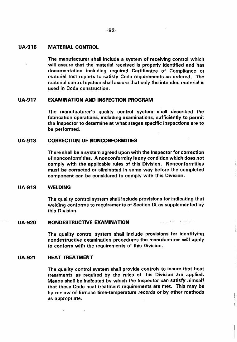
UA-916 MATERIAL CONTROL
The manufacturer shall include a system of receiving control which will assure that the material received is properly identified and has documentation including required Certificates of Compliance or material test reports to satisfy Code requirements as ordered. The nlateriol control system shall assure that only the intended material is used in Code construction.
UA-917 EXAMINATION AND INSPECTION PROGRAM
The manufacturer's quality control system shall described the fabrication operations, including examinations, sufficiently to permit the lnspector to determine at what stages specific inspections are to be performed.
UA-9 1 8 CORRECTION OF NONCONFORMITIES
There shall be a system agreed upon with the lnspector for correction of nonconformities. A nonconformity is any condition which does not comply with the applicable rules of this Division. Nonconformities must be corrected or eliminated in some way before the completed component can be'considered to comply with this Division.
UA-919 WELDING
Tlie quality control system shall include provisions for indicating that welding conforms to requirements of Section IX as supplemented by this Division.
UA-920 NONDESTRUCTIVE EXAMINATION - ,- * -
The quality control system shall include provisions for identifying nondestructive examination procedures the manufacturer will apply to conform with the requirements of this Division.
UA-921 HEAT TREATMENT
The quality control system shall provide controls to insure that heat treatments as required by the rules of this Division are applied. Means shall be indicated by which the lnspector can satisfy himself that these Code heat treatment requirements are met. This may be by review of furnace time-temperature records or by other methods as appropriate.
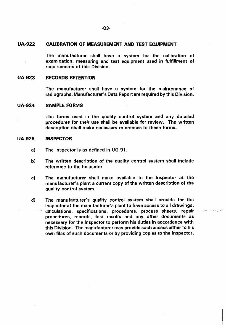
CALIBRATION OF MEASUREMENT AND TEST EQUIPMENT
The manufacturer shall have a system for the calibration of examination, measuring and test equipment used in fulfillment of requirements of this Division.
RECORDS RETENTION
The manufacturer shall have a system for the maintenance of radiographs, Manufacturer's Data Report are required by this Division.
SAMPLE FORMS
The forms used in the quality control system and any detailed procedures for their use shall be available for review. The written description shall make necessary references to these forms.
INSPECTOR
The lnspector is as defined in UG-91.
The written description of the quality control system shall include reference to the Inspector.
The manufacturer shall make available to the lnspector at the manufacturer's plant a current copy of the written description of the quality control system.
The manufacturer's quality control system shall provide for the lnspector at the manufacturer's plant to have access to all drawings, crzrlclr9ationsI specifications, procedures, process sheets, repair - -- - - -- procedures, records, test results and any other documents as necessary for the lnspector to perform his duties in accordance with this Division. The manufacturer may provide such access either to his own files of such documents or by providing copies to the Inspector.
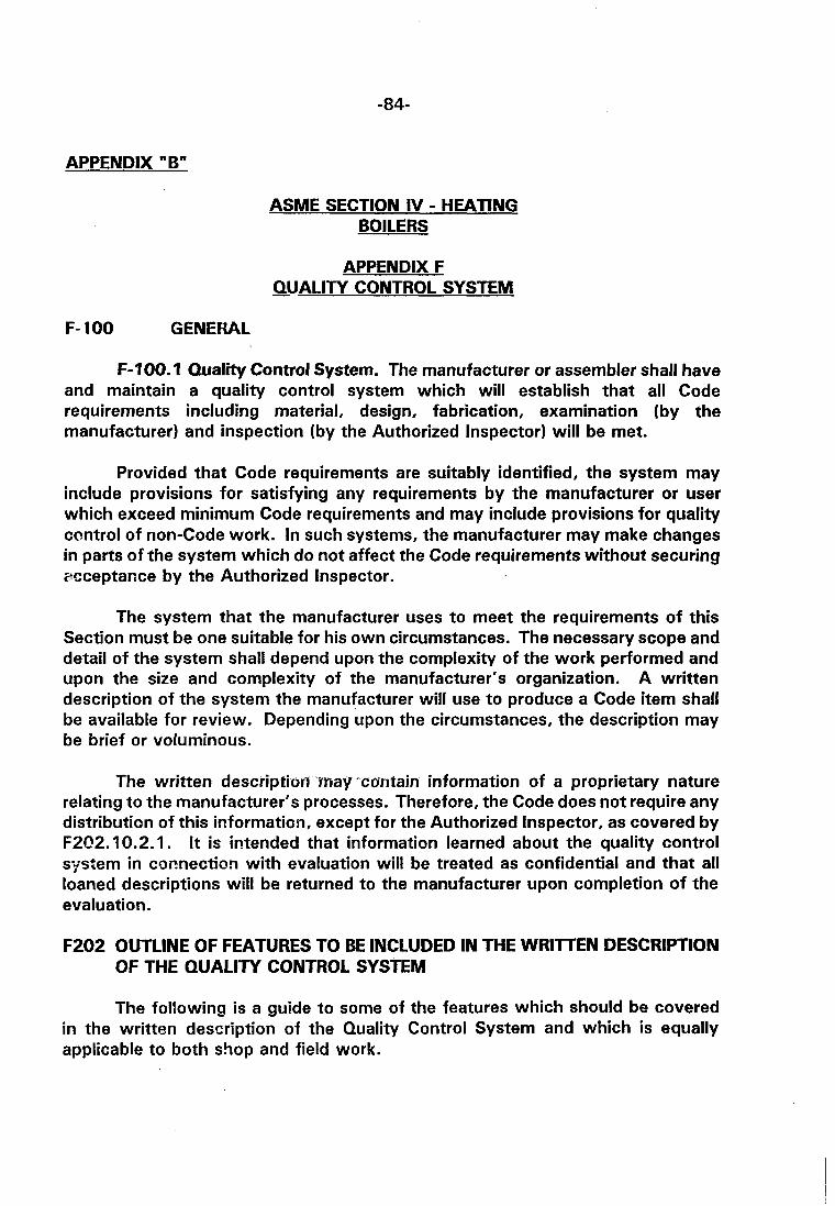
APPENDIX "B"
ASME SECTION IV - HEATING BOILERS
APPENDIX F QUALITY CONTROL SYSTEM -
F- 100 GENEKAL
F-700.7 Quality Control System. The manufacturer or assembler shall have and maintain a quality control system which will establish that all Code requirements including material, design, fabrication, examination (by the manufacturer) and inspection (by the Authorized Inspector) will be met.
Provided that Code requirements are suitably identified, the system may include provisions for satisfying any requirements by the manufacturer or user which exceed minimum Code requirements and may include provisions for quality control of non-Code work. In such systems, the manufacturer may make changes in parts of the system which do not affect the Code requirements without securing acceptance by the Authorized Inspector.
The system that the manufacturer uses to meet the requirements of this Section must be one suitable for his own circumstances. The necessary scope and detail of the system shall depend upon the complexity of the work performed and upon the size and complexity of the manufacturer's organization. A written description of the system the manufacturer will use to produce a Code item shall be available for review. Depending upon the circumstances, the description may be brief or voluminous.
The written description may -contain information of a proprietary nature relating to the manufacturer's processes. Therefore, the Code does not require any distribution of this information, except for the Authorized Inspector, as covered by F202.10.2.1. It is ifitended that information learned about the quality control system in co~nect ion with evaluation will be treated as confidential and that all loaned descriptions will be returned to the manufacturer upon completion of the evaluation.
F202 OUTLINE OF FEATURES TO BE INCLUDED IN THE WRllTEN DESCRIPTION OF THE QUALITY CONTROL SYSTEM
The following is a guide to some of the features which should be covered in the written description of the Quality Control System and which is equally applicable to both shop and field work.
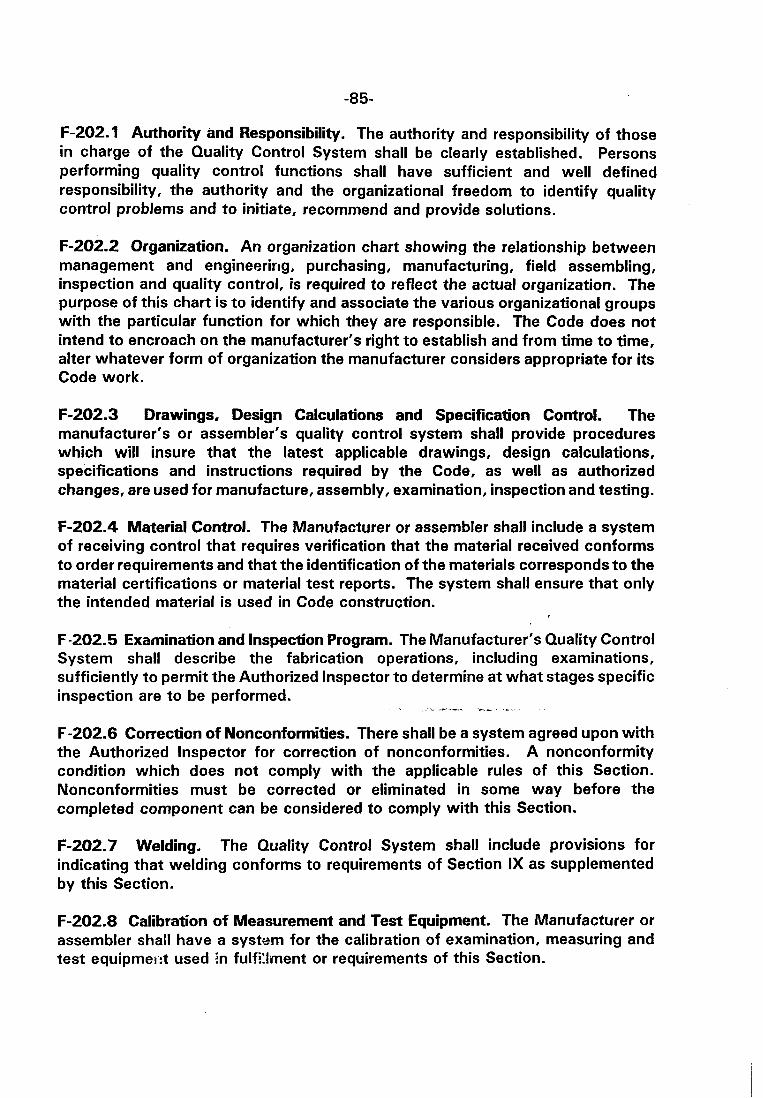
F-202.1 Authority and Responsibility. The authority and responsibility of those in charge of the Quality Control System shall be clearly established. Persons performing quality control functions shall have sufficient and well defined responsibility, the authority and the organizational freedom to identify quality con$rol problems and to initiate, recommend and provide solutions.
F-202.2 Organization. An organization chart showing the relationship between management and engineering, purchasing, manufacturing, field assembling, inspection and quality control, is required to reflect the actual organization. The purpose of this chart is to identify and associate the various organizational groups with the particular function for which they are responsible. The Code does not intend to encroach on the manufacturer's right to establish and from time to time, alter whatever form of organization the manufacturer considers appropriate for its Code work.
F-202.3 Drawings, Design Calculations and Specification Control. The manufacturer's or assembler's quality control system shall provide procedures which will insure that the latest applicable drawings, design calculations, specifications and instructions required by the Code, as well as authorized changes, are used for manufacture, assembly, examination, inspection and testing.
F-202.4 Material Control. The Manufacturer or assembler shall include a system of receiving control that requires verification that the material received conforms to order requirements and that the identification of the materials corresponds to the material certifications or material test reports. The system shall ensure that only the intended material is used in Code construction.
F-202.5 Examination and Inspection Program. The Manufacturer's Quality Control System shall describe the fabrication operations, including examinations, sufficiently to permit the Authorized Inspector to determine at what stages specific inspection are to be performed.
" - -- e- #
F-202.6 Correction of Nonconformities. There shall be a system agreed upon with the Authorized lnspector f ~ r correction of nonconformities. A nonconformity condition which does not comply with the applicable rules of this Section. Nonconformities must be corrected or eliminated in some way before the completed component can be considered to comply with this Section.
F-202.7 Welding. The Quality Control System shall include provisions for indicating that welding conforms to requirements of Section IX as supplemented by this Section.
F-202.8 Calibration o f Measurement and Test Equipment. The Manufacturer or assembler shall have a system for the calibration of examination, measuring and test equiprner.:t used In fulfillment or requirements of this Section.

F-202.9 Sample Forms. The forms used in the Quality Control System and any detailed procedures for their use shall be available for review. The written description shall make necessary references to these forms.
F-202.10 Authorized lnspector
F-202.10.1 The authorized lnspector is the ASME Code lnspector defined in HG- 51 5.2.
F-202.10.2 The written description of the Quality Control System shall include reference to the Authorized Inspector.
F-202.10.2.1 The Manufacturer shall make available to the Authorized lnspector at the Manufacturer's plant a copy of the written description of the Quality Control System.
F-202.10.2.2 The Manufacturer's Quality Control System shall provide for the Authorized lnspector at the Manufacturer's plant to have access to all drawings, calculations, specifications, procedures, processsheets, repair procedures, records, test results and any other documents as necessary for the Authorized lnspector to perform his duties in accordance with this Section. The Manufacturer may provide such access either to his own files of such documents or by providing copies to the Authorized Inspector.

APPENDIX "C" CODES AND STANDARDS
ABBREVIATIONS AND ADDRESSES OF PUBLISHING ORGANISATIONS
AMERICAN ANSI
API
ARI
ASHRAE
ASME
ASTM
CTI
SMACNA
TEMA
UL
BRITISH BS
HVCA
IP
IR
OCMA
American National Standards Institute, 1430 Broadway, New York, NY 100018.
American Petroleum lnstitute Publications and Distribution Section, 2101L Street Northwest, Washington, D.C. 20037.
Air-conditioning and Refrigeration Institute, North Fort Myer Drive, Arlington, Virginia, VA 22209.
American Society of Heating, Refrigerating and Air-conditioning Engineers, Inc., 345 East 47th St., New York, NY 10017.
American Society of Mechanical Engineers, 345 East 47th St., New York, NY 1001 7.
American Society for Testing and Materials, 1916 Race St., Philadelphia, PA 19103.
Cooling Tower lnstitute Suite 216, 9030 N. Freeway, Houston, TX 77037.
Sheet Metal and Air Conditioning Contractor's National Association, 8224 Old Courthouse Rd., Tysons Corner, Vienna, VA 21880.
Tubular Exchanger Manufacturers Association, Inc., 331 Madison Ave., New York, NY 10017.
U n d M b W ' t a b o - r a t o r i e s , Inc., 333 Pfingston Rd., Northbrook, IL 60062.
British Standards Institution, 2 Part St., London, WIA ZBS.
Heating and Ventilating Contractor's Association, Publications Dept., 10 King Str., Penrith, Cumbria CA 11 7AJ.
lnstitute of Petroleum, 61 New Cavendish Street, London W I M 8AR.
lnstitute of Refrigeration, 272 London Road, Wallington, Surrey SM6 7DJ.
Oil Companies Materials Association, Cecil Chambers, 86 Strand, London, WCZR ODX.