20
Masoneilan ® 39003 Series High Performance Butterfly Valves (HPBV) Specification Data CM9003 4/00
| Date post: | 26-Oct-2015 |
| Category: |
Documents |
| Upload: | sergio-ivan |
| View: | 10 times |
| Download: | 2 times |
Masoneilan®
39003 SeriesHigh PerformanceButterfly Valves (HPBV)
Specification Data
CM9003
4/00

SD CM9003 4/0039003 Series2
The Masoneilan 39003 Series High PerformanceButterfly Valve (HPBV) is a heavy duty automaticthrottling control valve that incorporates the twobasic features of the HPBV types. These featuresdifferentiate the HPBV from the conventional swing-through butterfly valve in regards to sealing methodand operational characteristics. Specifically, the twobasic features are: (1) A PTFE, RTFE, or metal sealring instead of a liner, and (2) The employment ofdouble offset (eccentric operation). Each of thesefeatures contributes to the improved performance ofHPBV’s compared to conventional butterfly valves.
The use of a seal ring (PTFE, RTFE, or metal)eliminates the inherent problems of high sealingforces, due to interference fit, and the resultant highwear rates due to scraping and scuffing of liners.Also, due to the design of the seal itself, which is adynamic pressure-assisted member, ANSI Class VIshutoff rates are available throughout the full rangeof ANSI Class 150, 300 and 600 ratings (soft-sealedconstructions only).
The double offset (eccentric) operating principlesof both seal offset (the seal ring centerline is offsetfrom the shaft centerline - see Figure 1) and shaftoffset (the shaft centerline is offset from the valve
Foreword . . . . . . . . . . . . . . . . . . . . . . . . . . . . . . . . . . . . . . . . . . . . . . . . . . . . . . . . . . . . . . . . . . 2
Features . . . . . . . . . . . . . . . . . . . . . . . . . . . . . . . . . . . . . . . . . . . . . . . . . . . . . . . . . . . . . . . . . . 3
Numbering System . . . . . . . . . . . . . . . . . . . . . . . . . . . . . . . . . . . . . . . . . . . . . . . . . . . . . . . . 4-5
General Data . . . . . . . . . . . . . . . . . . . . . . . . . . . . . . . . . . . . . . . . . . . . . . . . . . . . . . . . . . . . . . . 6
Pressure/Temperature Ratings . . . . . . . . . . . . . . . . . . . . . . . . . . . . . . . . . . . . . . . . . . . . . . . 7-8
Body Assembly Data . . . . . . . . . . . . . . . . . . . . . . . . . . . . . . . . . . . . . . . . . . . . . . . . . . . . . . . . . 9
Actuator Data . . . . . . . . . . . . . . . . . . . . . . . . . . . . . . . . . . . . . . . . . . . . . . . . . . . . . . . . . . . . . . 9
Rated Flow Coefficients (CV) and Pressure Recovery Coefficients (FL) . . . . . . . . . . . . . . . . 10
Standard Valve Components . . . . . . . . . . . . . . . . . . . . . . . . . . . . . . . . . . . . . . . . . . . . . . . . . 11
Standard Materials of Construction . . . . . . . . . . . . . . . . . . . . . . . . . . . . . . . . . . . . . . . . . . 12-13
Allowable Pressure Drops . . . . . . . . . . . . . . . . . . . . . . . . . . . . . . . . . . . . . . . . . . . . . . . . . . . . 14
Weights . . . . . . . . . . . . . . . . . . . . . . . . . . . . . . . . . . . . . . . . . . . . . . . . . . . . . . . . . . . . . . . 15-16
Dimensions . . . . . . . . . . . . . . . . . . . . . . . . . . . . . . . . . . . . . . . . . . . . . . . . . . . . . . . . . . . . 17-18
Options and Accessories . . . . . . . . . . . . . . . . . . . . . . . . . . . . . . . . . . . . . . . . . . . . . . . . . . . . 19
Masoneilan Sales Offices . . . . . . . . . . . . . . . . . . . . . . . . . . . . . . . . . . . . . . . . . . . . . . . . . . . . 20
Foreword
Table of Contents
centerline – see Figure 1) allows the disc to get off theseal quickly due to the camming rotation with respectto the valve/seal centerlines. This results in minimalsliding (friction producing) contact between the discand the seal ring with complete separation after onlya few degrees of rotation.
The overall characteristics of the 39003 Series arelisted below:
• Long seal life – Offset (eccentric) operationgets the disc off the seal quickly, minimizingsliding contact and friction, resulting inreduced seal wear and lower breakaway andseating torque requirements.
• Fast/dynamic operation – Offset (eccentric)operation eliminates disc-to-seal frictionthroughout the operating range resulting infast response to input signals. Also, thedisc tends to move in the direction of flow,assisting the valve and actuator to maximizethe allowable operating pressures.
Trade names noted are for reference only. Masoneilan reservesthe right to supply trade-named material or equivalent.

3SD CM9003 4/0039003 Series
• Excellent flow characteristics - the offset
(eccentric) disc design provides an approximate
equal percentage flow characteristic through its full
travel of 90° rotation yielding a Cv ratio of 100:1.
• Extra heavy shafts with keyed ends for actuator
mounting - precise and accurate positioning
without lost motion or backlash.
PTFE-lined low-friction bearing – Reduces operating torque
and promotes fast response to valve and actuator action. The
triple bearing support of the shaft prevents deflection of the
shaft due to side-loading and incorporates a grounding circuit.
Features
The Masoneilan 39003 HPBV includes unique valve seal designs for metal, soft seal, and fire-safe configurations.
Field replaceable components – Unlike most competitive
valves, shaft and disc need not be purchased as a set. The
39003 Series uses tapered pins to attach the shaft and disc
positively, yet provide component interchangeability.
The soft seal design provides abi-directional bubble tight shutoff (zeroleakage) through the use of a patentedseal. This unique seal design createsa self-energized seal in vacuum-to-lowpressure applications.
Under higher pressure conditions,the seal is also designed to confineand direct movement of the soft sealagainst the disc edge, up to the full ANSIClass 150, 300 and 600 Cold WorkingPressures.
The soft seal is designed for highservices with minimal wear and lowtorque. Seal replacement is a simpleprocedure requiring no special tools.
���������
��
���������
���������������������
������
���������
�
The fire-safe seal design incorpo-rates two patented seals which functiontogether to seal off pipeline flow. Innormal operation, the soft seal providesa bi-directional “bubble tight” shutoff(zero leakage); the metal seal providesbi-directional shutoff in the event ofa fire, in conformance to industry fire-safe requirements.
With little or no pressure, the fire-safe seal creates a self-energized sealagainst the disc. Higher line pressuresact on the geometry of both sealsto dynamically load them against thedisc, creating higher sealing forces ineither direction.
The metal seal is made of Inconelmaterial which is shaped by a propri-etary hydroforming process into itsunique, patented design. Stainless steelouter bearings are included for post-fire disc and shaft alignment. Fireproofpacking is used to prevent external shaftleakage.
Disc
The metal seal design incorporatesan Inconel seal for higher tensilestrength, a 300 series stainless steelback-up ring in the seal cavity for axialseal support, and a disc that is casehardened by nitriding.
The Inconel seal, by its dynamic andflexible design, applies enough forceper linear inch against the disc edge(Rockwell Hardness of C66 to C70) toobtain an optimum sealing characteris-tic while controlling the loads betweenthe metal surfaces.
The metal seal design can beutilized for temperatures up to 900˚F,in compliance with ANSI B16.34pressure/temperature specifications.Leakage is rated at Class IV per ANSIFCI 70-2.
SealOffset
Shaft Center Line
Shaft Offset
Shaft CenterLine
Valve CenterLine Flow to Close
Flow to Open(Preferred)
Seal“O” Ring
Disc
Metal Seal
“O” Ring
Soft Seal
MetalSeal
Gasket���������
��
���������
���������������������
������
���������
�
Disc/Nitrided
300 SeriesStainless SteelBackup Ring
InconelSeal
Figure 1
Metal Seal Design Soft Seal Design Fire-Safe Seal Design
SD CM9003 4/0039003 Series4
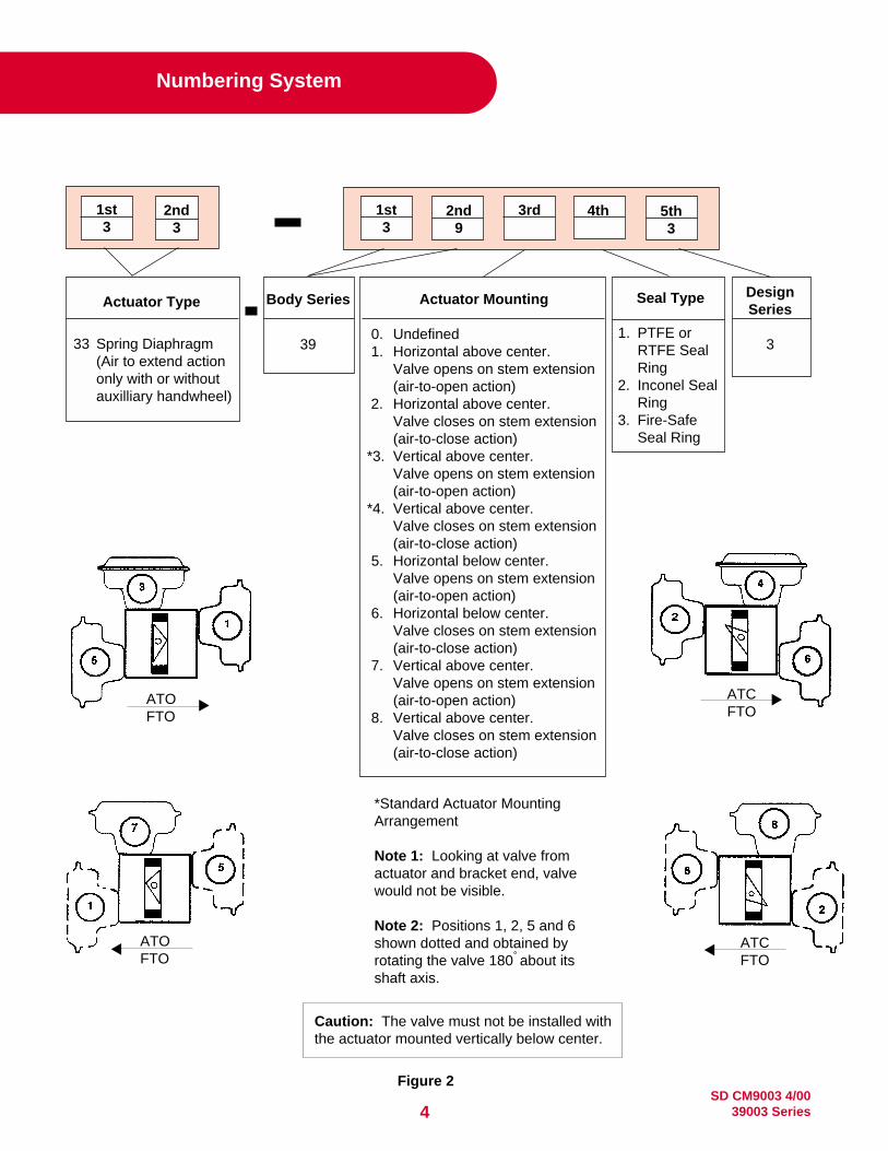
2nd3
Seal Type
1. PTFE orRTFE SealRing
2. Inconel SealRing
3. Fire-SafeSeal Ring
Body Series
39
2nd9
5th3
4th3rd
33 Spring Diaphragm(Air to extend actiononly with or withoutauxilliary handwheel)
1st3
1st3
Actuator TypeDesignSeries
3
Numbering System
*Standard Actuator MountingArrangement
Note 1: Looking at valve fromactuator and bracket end, valvewould not be visible.
Note 2: Positions 1, 2, 5 and 6shown dotted and obtained byrotating the valve 180° about itsshaft axis.
Caution: The valve must not be installed withthe actuator mounted vertically below center.
Figure 2
ATCFTO
ATOFTO
ATCFTO
ATOFTO
Actuator Mounting
0. Undefined1. Horizontal above center.
Valve opens on stem extension(air-to-open action)
2. Horizontal above center.Valve closes on stem extension(air-to-close action)
*3. Vertical above center.Valve opens on stem extension(air-to-open action)
*4. Vertical above center.Valve closes on stem extension(air-to-close action)
5. Horizontal below center.Valve opens on stem extension(air-to-open action)
6. Horizontal below center.Valve closes on stem extension(air-to-close action)
7. Vertical above center.Valve opens on stem extension(air-to-open action)
8. Vertical above center.Valve closes on stem extension(air-to-close action)

5SD CM9003 4/0039003 Series
2nd4
2nd9
5th3
4th3rd1st3
1st3
Figure 3
Seal Type
1. PTFE orRTFE SealRing
2. Inconel SealRing
3. Fire-SafeSeal Ring
Body Series
3934 Double acting orspring return pistonactuator
Actuator TypeDesignSeries
3
Actuator Mounting
0. Undefined*1. Parallel to pipe.
Air to open action.*2. Parallel to pipe.
Air to close action. 3. Perpendicular to pipe.
Air to open action. 4. Perpendicular to pipe.
Air to close action.5. Parallel to pipe.
Air to open action. 6. Parallel to pipe.
Air to close action. 7. Perpendicular to pipe.
Air to open action. 8. Perpendicular to pipe.
Air to close action.
Numbering System
*Standard Actuator MountingArrangement
SD CM9003 4/0039003 Series6
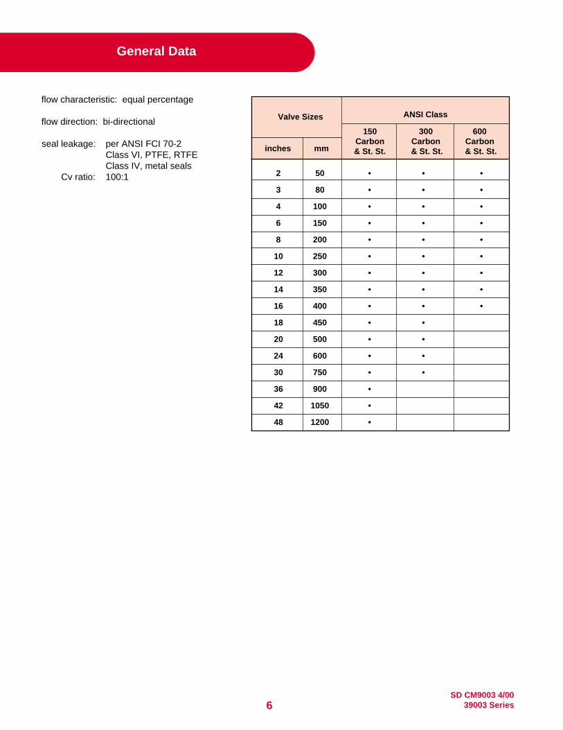
General Data
flow characteristic: equal percentage
flow direction: bi-directional
seal leakage: per ANSI FCI 70-2Class VI, PTFE, RTFEClass IV, metal seals
Cv ratio: 100:1 2 50 • • •
3 80 • • •
4 100 • • •
6 150 • • •
8 200 • • •
10 250 • • •
12 300 • • •
14 350 • • •
16 400 • • •
18 450 • •
20 500 • •
24 600 • •
30 750 • •
36 900 •
42 1050 •
48 1200 •
Valve Sizes
inches mm
ANSI Class
150 300 600Carbon Carbon Carbon& St. St. & St. St. & St. St.

7SD CM9003 4/0039003 Series
Pressure/Temperature Ratings
Soft and Fire-Safe SealAs temperature increases, the pressure retaining capability of materials decreases. The graph below illustrates thepressure/temperature ratings for ANSI Class 150, Class 300 and Class 600.
The heavy lines define the ratings of the carbon steel and stainless steel valve body (or “shell”) in conformance to ANSIB16.34. The shaded areas define the ratings of the PTFE and RTFE Seal materials (Soft Seal).
Seal ratings are based on differential pressure with the disc in the fully closed position.*
Steam Service (Soft Seal only)PTFE sealed valves are rated for 50 psi saturated steam.Valves with "O" seal configuration (RTFE seal/AFLAS O-ring) are rated to 100 psi steam service.
* Valves with 316SS shafts are rated for maximum pressure differentials of 150 psi for Class 150, 300 psi for Class 300,and 600 psi for Class 600.
1500
1400
1300
1200
1100
1000
900
800
700
600
500
400
300
200
100
0500400300200100-100 0
Wor
king
Pre
ssur
e -P
SIG
Wor
king
Pre
ssur
e -B
AR
G
103.4
96.5
89.6
82.7
75.8
68.9
62.1
55.2
48.3
41.4
34.5
27.6
20.7
13.8
6.9
26020414993.338.7-73 -17.8
ANSI B16.34 Body and Flowseal Soft Seat Pressure - Temperature Ratings
ANSI 600 CS
ANSI 600 SS
-20
°F L
OW
TE
MP
CS
LIM
IT
ANSI 300 CS
ANSI 150 SS
ANSI 300 SS
TFE
Temperature - °F
Temperature - °C
1480
RTFE
ANSI 150 CS
SD CM9003 4/0039003 Series8
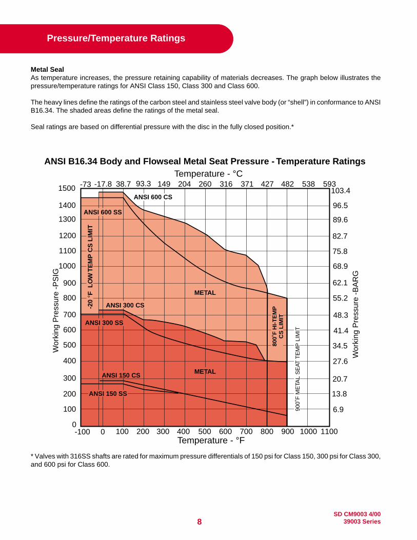
Pressure/Temperature Ratings
Metal SealAs temperature increases, the pressure retaining capability of materials decreases. The graph below illustrates thepressure/temperature ratings for ANSI Class 150, Class 300 and Class 600.
The heavy lines define the ratings of the carbon steel and stainless steel valve body (or “shell”) in conformance to ANSIB16.34. The shaded areas define the ratings of the metal seal.
Seal ratings are based on differential pressure with the disc in the fully closed position.*
* Valves with 316SS shafts are rated for maximum pressure differentials of 150 psi for Class 150, 300 psi for Class 300,and 600 psi for Class 600.
1500
1400
1300
1200
1100
1000
900
800
700
600
500
400
300
200
100
0500 600 700 800 900 1000 1100400300200100-100 0
Wor
king
Pre
ssur
e -P
SIG
Wor
king
Pre
ssur
e -B
AR
G
103.4
96.5
89.6
82.7
75.8
68.9
62.1
55.2
48.3
41.4
34.5
27.6
20.7
13.8
6.9
260 316 371 427 482 538 59320414993.338.7-73 -17.8
ANSI B16.34 Body and Flowseal Metal Seat Pressure - Temperature Ratings
ANSI 600 CS
ANSI 300 CS
METAL
Temperature - °F
Temperature - °C
METAL
ANSI 150 CS
ANSI 300 SS
ANSI 600 SS
900˚
F M
ETA
L S
EAT
TE
MP
LIM
IT
800˚
F H
I-T
EM
PC
S L
IMIT
-20
°F L
OW
TE
MP
CS
LIM
IT
ANSI 150 SS

9SD CM9003 4/0039003 Series
Body Assembly Data
Body Type: wafer or lug with integral bonnetSizes: 2”, 3”, 4”, 6”, 8”, 10”, 12”, 14”, 16”, 18”, 20”, 24”, 30”, 36”, 42”, 48” (50 mm-1200 mm)
Materials: carbon steel ASTM A216 Gr WCB or ASTM A105stainless steel ASTM A351 Gr CF8M or ASTM A182-F316
Connections: flangeless - clamped between ANSI Class 150, 300 or 600 line flangessingle flanged - bolts between ANSI Class 150, 300 or 600 line flanges
Rating: ANSI Class 150 - carbon steel and stainless steel 2” - 48” sizes (50 mm-1200 mm)ANSI Class 300 - carbon steel and stainless steel 2” - 30” sizes (50 mm-750 mm)ANSI Class 600 - carbon steel and stainless steel 2” - 16” sizes (50 mm-400 mm)
Seal: PTFE, RTFE or Inconel with 304 stainless steel O-RingDisc Type: offset eccentric disc
Materials: stainless steel ASTM A351 Gr CF8M or ASTM A182-F316 NitridedShaft Type: Keyed on outboard end
Materials: 17-4 PH stainless steel A564 Gr 630 (others optional)Valve Bearings: PTFE-lined fiberglass
bronze (up to 750° F) stainless steel (above 750° F)Packing Box: bolted
Packing: PTFE V-ringgraphite (optional)
Actuator Data
(Model 33) – Sizes 3” – 8” (80mm-200mm)Type: spring-diaphragm, floating stem
pneumatic actuatorAction: increasing air extends stem
Bench Range: B size 7-16 psig (48-110 kPa)C size 9-16 psig (62-110 kPa)
Connection: 1/4” NPTFail Safe Action: field reversible
Yoke: carbon steelBracket: cast iron
Handwheel:(optional) push type tilting, rising stem, permanently
lubricated materials: 17-4 PH and AISI416 stainless steel adjustable limit stops
Bracket Bearing: a sealed, permanently lubricated ball bearing
(Model 34) – Sizes 3” – 48” (80mm – 1200mm)Type: Spring-return, or double-acting scotch yoke pistonBody: Extruded aluminum, anodized finish – sizes 210 to 280 & 88
Ductile Iron – sizes 90 and 100Seals: Buna-N
Pressure Rating: 150 psi (1034 kPa) maximum working pressureManual Override: Declutchable direct mount – sizes 210 to 280
Hydraulic – size 88Bevel Gear – sizes 90 and 100
OptionalConstruction: Low temperature or high temperature seals, low pressure hydraulic.
EffectiveActuator Valve Size Area Travel
Size in. (mm) sq.in. (sq. cm) in. (mm)
B3 (80)
70 (452) 2.625 (66.5)4 (100)
6 (150)
8 (200)
C optional 140 (903) 2.625 (66.5)
3 (80)
4 (100)
SD CM9003 4/0039003 Series10
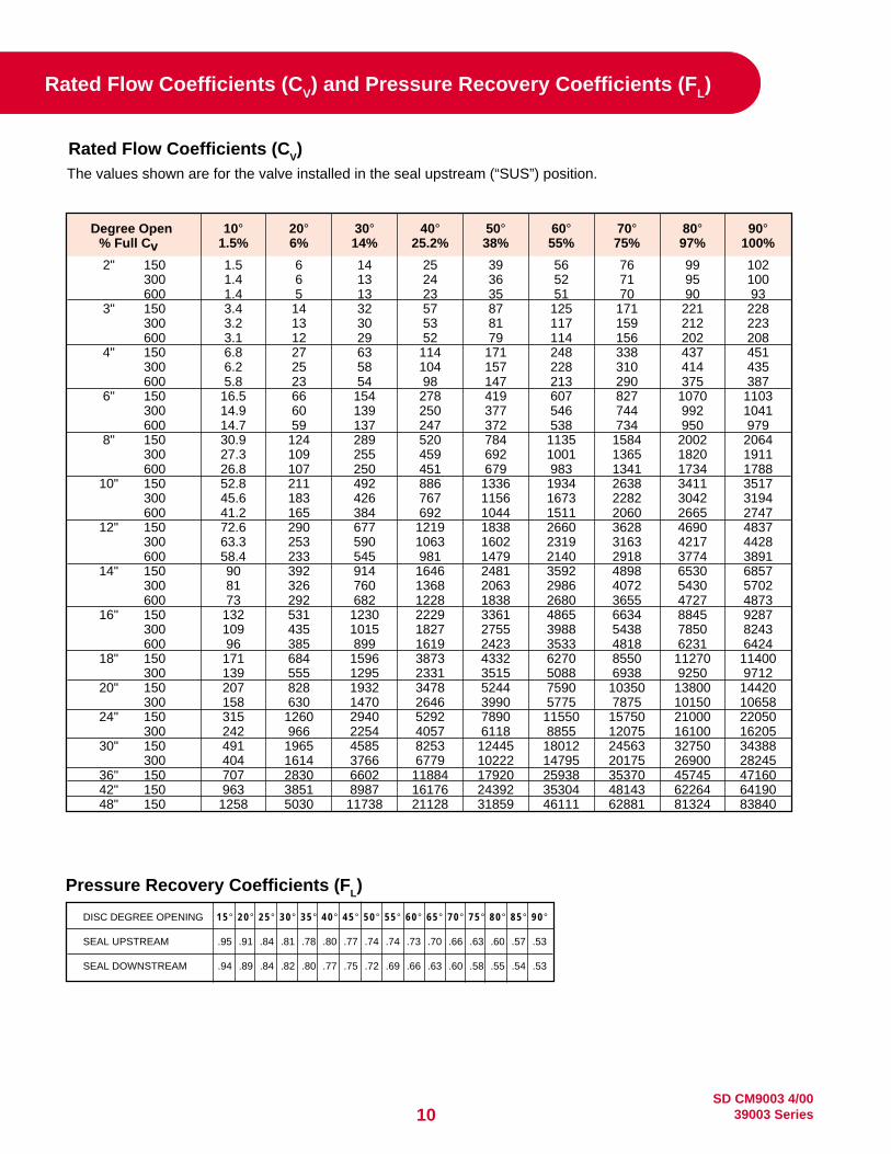
Rated Flow Coefficients (CV) and Pressure Recovery Coefficients (FL)
Degree Open 10° 20° 30° 40° 50° 60° 70° 80° 90°% Full Cv 1.5% 6% 14% 25.2% 38% 55% 75% 97% 100%
2" 150 1.5 6 14 25 39 56 76 99 102300 1.4 6 13 24 36 52 71 95 100600 1.4 5 13 23 35 51 70 90 93
3" 150 3.4 14 32 57 87 125 171 221 228300 3.2 13 30 53 81 117 159 212 223600 3.1 12 29 52 79 114 156 202 208
4" 150 6.8 27 63 114 171 248 338 437 451300 6.2 25 58 104 157 228 310 414 435600 5.8 23 54 98 147 213 290 375 387
6" 150 16.5 66 154 278 419 607 827 1070 1103300 14.9 60 139 250 377 546 744 992 1041600 14.7 59 137 247 372 538 734 950 979
8" 150 30.9 124 289 520 784 1135 1584 2002 2064300 27.3 109 255 459 692 1001 1365 1820 1911600 26.8 107 250 451 679 983 1341 1734 1788
10" 150 52.8 211 492 886 1336 1934 2638 3411 3517300 45.6 183 426 767 1156 1673 2282 3042 3194600 41.2 165 384 692 1044 1511 2060 2665 2747
12" 150 72.6 290 677 1219 1838 2660 3628 4690 4837300 63.3 253 590 1063 1602 2319 3163 4217 4428600 58.4 233 545 981 1479 2140 2918 3774 3891
14" 150 90 392 914 1646 2481 3592 4898 6530 6857300 81 326 760 1368 2063 2986 4072 5430 5702600 73 292 682 1228 1838 2680 3655 4727 4873
16" 150 132 531 1230 2229 3361 4865 6634 8845 9287300 109 435 1015 1827 2755 3988 5438 7850 8243600 96 385 899 1619 2423 3533 4818 6231 6424
18" 150 171 684 1596 3873 4332 6270 8550 11270 11400300 139 555 1295 2331 3515 5088 6938 9250 9712
20" 150 207 828 1932 3478 5244 7590 10350 13800 14420300 158 630 1470 2646 3990 5775 7875 10150 10658
24" 150 315 1260 2940 5292 7890 11550 15750 21000 22050300 242 966 2254 4057 6118 8855 12075 16100 16205
30" 150 491 1965 4585 8253 12445 18012 24563 32750 34388300 404 1614 3766 6779 10222 14795 20175 26900 28245
36" 150 707 2830 6602 11884 17920 25938 35370 45745 4716042" 150 963 3851 8987 16176 24392 35304 48143 62264 6419048" 150 1258 5030 11738 21128 31859 46111 62881 81324 83840
Rated Flow Coefficients (CV)The values shown are for the valve installed in the seal upstream (“SUS”) position.
DISC DEGREE OPENING 15° 20° 25° 30° 35° 40° 45° 50° 55° 60° 65° 70° 75° 80° 85° 90°
SEAL UPSTREAM .95 .91 .84 .81 .78 .80 .77 .74 .74 .73 .70 .66 .63 .60 .57 .53
SEAL DOWNSTREAM .94 .89 .84 .82 .80 .77 .75 .72 .69 .66 .63 .60 .58 .55 .54 .53
Pressure Recovery Coefficients (FL)

11SD CM9003 4/0039003 Series
Common materials are TFE for up to 450˚Fand Graphite for up to 900˚F.
Lower Packing VariationThe ANSI 150 30" through 48"; ANSI 300 14"
through 30"; ANSI 600 10" through 16" sizesfeature a two-piece shaft design which utilizes
a lower packing seal in the valve body toprevent external leakage. The component
parts are of the same design used in thepacking assembly in the top of the
valve body neck.
DISC360˚ uninterupted sphericaledge for sealing. Profile isdesigned for maximum flowand equal percentage control.
DISC SPACERSDisc is centered by use of thrustspacers around shaft in sizes 2"to 4". Disc position stops or thrustbolt arrangements are used forlarger sizes.
PACKING GLAND
BODYANSI B16.34 design in either waferor lug configuration.
KEY
PACKING
GLAND FLANGE
SHAFTSolid blow out proof shaft provides alignmentand rigid support for disc.
Separate part from gland flange, preventinguneven load distribution against packing.
Square key valve-to-operator connectionprovides an externally controlled failure pointupon over-torquing.
Applies load against packing gland to preventexternal leakage. Fully adjustable.
BEARINGSBoth above and below the disc,bearings maintain shaft alignment.Common materials include:Glass-backed TFE for up to 450˚F.(Not for steam service.)Luberized Bronze for up to 750˚F.300 Series Stainless Steel Nitridedfor up to 900˚F.
End Seal VariationThe ANSI 150 14" through 24" sizes feature atwo-piece shaft design. The lower shaft utilizesan end seal in the body to prevent external
leakage. The component parts include anend seal, an end cap and end cap bolts.
OVERTRAVEL STOPPrevents disc from over-rotating.
SEALPatented seal design for tight shutoff.
SET SCREWSCone point screws force wedgering outward to lock seal retainer inposition on valve sizes 2" through30". Socket head cap screws areused on valve sizes 36" and larger.
RETAINER RINGRetains seal in valve. Standardsurface finish is 125 to 250 AARHand is compatible with both standardgaskets and spiral wound gasketdesigns. Outside diameter isrecessed within gasket sealingsurface to prevent external leakage.
WEDGE RINGStainless steel band wedged between valvebody and retainer ring by set screws to lockseal and retainer ring in position on valve sizes2" through 30". Socket head cap screws areused on valve sizes 36" and larger.
WEDGE PINSProvide positive mechanical attachment ofdisc to shaft.
END SEAL
END CAP
BOLTS
PACKING
GLAND
GLAND FLANGESTUDS & NUTS
1.2.
4.
6.
8.
10.
12.
15.
14.
13.
11.
9.
7.
5.
3.
Figure 4
Standard Valve Components
SD CM9003 4/0039003 Series12
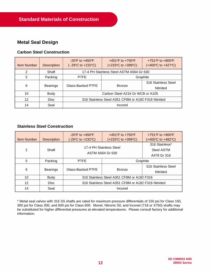
Standard Materials of Construction
Metal Seal Design
Carbon Steel Construction
-20oF to +450oF +451oF to +750oF +751oF to +800oFItem Number Description (- 29oC to +232oC) (+233oC to +399oC) (+400oC to +427oC)
2 Shaft 17-4 PH Stainless Steel ASTM A564 Gr 630
5 Packing PTFE Graphite
6 Bearings Glass-Backed PTFE Bronze316 Stainless Steel
Nitrided
10 Body Carbon Steel A216 Gr WCB or A105
12 Disc 316 Stainless Steel A351 CF8M or A182 F316 Nitrided
14 Seal Inconel
Stainless Steel Construction
-20oF to +450oF +451oF to +750oF +751oF to +900oFItem Number Description (-29oC to +232oC) (+233oC to +399oC) (+400oC to +482oC)
17-4 PH Stainless Steel316 Stainless*
2 ShaftASTM A564 Gr 630
Steel ASTM
A479 Gr 316
5 Packing PTFE Graphite
6 Bearings Glass-Backed PTFE Bronze316 Stainless Steel
Nitrided
10 Body 316 Stainless Steel A351 CF8M or A182 F316
12 Disc 316 Stainless Steel A351 CF8M or A182 F316 Nitrided
14 Seal Inconel
* Metal seal valves with 316 SS shafts are rated for maximum pressure differentials of 150 psi for Class 150,300 psi for Class 300, and 600 psi for Class 600. Monel, Nitronic 50, and Inconel (718 or X750) shafts maybe substituted for higher differential pressures at elevated temperatures. Please consult factory for additionalinformation.

13SD CM9003 4/0039003 Series
Standard Materials of Construction
Soft Seal Design
Item Number Description-100oF to +400oF +400oF to +500oF
(- 88oC to +204oC) (+204oC to +260oC)
17-4 PH Stainless Steel ASTM A564 Gr 630
2 Shaft Optional: 316 SS, Inconel 718/750, Monel, Alloy 20,
Nitronic 50, Hastelloy C, and Others
5 PackingTFE
Optional: Graphite
6 BearingsGlass Backed PTFE
Optional: 316 SS Backed TFE, Hastelloy C Backed TFE
Carbon Steel A216 Gr WCB or A105
10 Body Optional: 316 SS ASTM A351 CF8M or A182 F316,
Monel, Alloy 20, Aluminum Bronze, or Hastelloy C
12 Disc316 Stainless Steel A351 CF8M or A182 F316
Optional: Monel, Alloy 20, Aluminum Bronze, or Hastelloy C
14 SealPTFE
Optional: RTFE, Polyethylene (UHMWPE)
Fire-Safe Design
Item Number Description -100oF to +400oF +400oF to +500oF(- 88oC to +204oC) (+204oC to +260oC)
2 Shaft17-4 PH Stainless Steel ASTM A564 Gr 630
Optional: 316 Stainless Steel
5 Packing Fire-Safe
6 Bearings Fire-Safe (Garfil & 316 SS)
Carbon Steel A216 Gr WCB or A105
10 Body Optional: 316 SS ASTM A351 CF8M or A182 F316,
Monel, Alloy 20, Hastelloy C, and Others
12 Disc316 Stainless Steel A351 CF8M or A182 F316 - ENP
Consult Factory for Optional Materials
Fire-Safe (TFE & Inconel) RTFE & Inconel
14 Seal Optional: TFE & Monel, RTFE & Monel,
TFE & Hastelloy C RTFE & Hastelloy C
SD CM9003 4/0039003 Series14
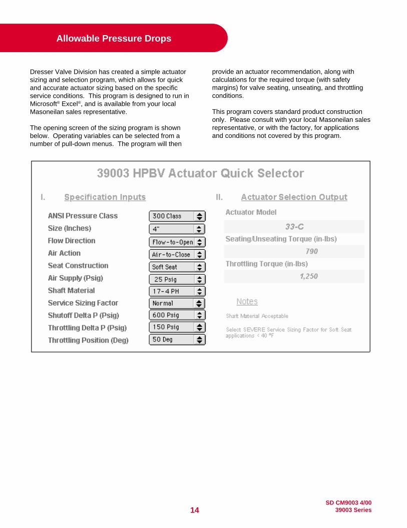
Dresser Valve Division has created a simple actuatorsizing and selection program, which allows for quickand accurate actuator sizing based on the specificservice conditions. This program is designed to run inMicrosoft® Excel®, and is available from your localMasoneilan sales representative.
The opening screen of the sizing program is shownbelow. Operating variables can be selected from anumber of pull-down menus. The program will then
Allowable Pressure Drops
provide an actuator recommendation, along withcalculations for the required torque (with safetymargins) for valve seating, unseating, and throttlingconditions.
This program covers standard product constructiononly. Please consult with your local Masoneilan salesrepresentative, or with the factory, for applicationsand conditions not covered by this program.

15SD CM9003 4/0039003 Series
Weights
HANDWHEEL WEIGHTSACTUATOR RC210 RC220 RC230 RC240 RC250 RC260 RC270 RC280 RC88 RC90&100 RC90&100
TYPE DA/SR DA/SR DA/SR DA/SR DA/SR DA/SR DA/SR DA/SR DA/SR DA SR 33 ACT.
WEIGHT 1.5 1.5 2.5 2.5 6.5 6.5 26 26 250 185 66 22
150 CLASS ASSEMBLIES
NOTES: 1. The weights of actuators are without handwheel2. The weights are in lbs.3. DA = Double Acting / SR = Spring Return
NOTES: 1. The weights are in lbs.
ACTUATOR TYPE RC210 RC220 RC230 RC240 RC250 RC260 RC270 RC280 RC88 RCI90 RCG100 33 ACTUATOR
VALVE VALVE BRACKET DA SR DA SR DA SR DA SR DA SR DA SR DA SR DA SR DA SR DA SR DA SR YOKE “B” “C”
SIZE TYPE WT WT 3.1 4 4 5.85 8 10.4 10.6 15.5 20.4 26.8 27 40 69 69 89 142 162 330 618 772 684 1102 WT 32 85
2" WAFER 8 12 23.1 24 24 25.85 28 30.4 30.6 35.5 24 64 117
LUG 11 12 26.1 27 27 28.85 31 33.4 33.6 38.5 24 67 120
3" WAFER 11 12 26.1 27 27 28.85 31 33.4 33.6 38.5 24 67 120
LUG 13 12 28.1 29 29 30.85 33 35.4 35.6 40.5 24 69 122
4" WAFER 17 12 32.1 33 33 34.85 37 39.4 39.6 44.5 24 73 126
LUG 25 12 40.1 41 41 42.85 45 47.4 47.6 52.5 24 81 134
6" WAFER 30 12 50 52.4 52.6 57.5 62.4 68.8 69 82 24 139
LUG 35 12 55 57.4 57.6 62.5 67.4 73.8 74 87 24 144
8" WAFER 44 12 71.5 76.4 82.8 83 96 125 125 24 153
LUG 48 12 75.5 80.4 86.8 87 100 129 129 24 157
10" WAFER 71 14 105.4 111.8 112 125 154 154 174 227
LUG 191 14 125.4 131.8 132 145 174 174 194 247
12" WAFER 110 14 157 170 199 199 219 272
LUG 127 14 174 187 216 216 236 289
14" WAFER 135 16 182 195 224 224 244 297
LUG 183 16 230 243 272 272 292 345
16" WAFER 182 20 271 271 291 344 364 532
LUG 250 20 339 339 359 412 432 600
18" WAFER 234 20 323 323 343 396 416 584 872 1026 938
LUG 305 20 394 394 414 467 487 655 943 1097 1009
20" WAFER 320 20 429 482 502 670 958 1112 1024
LUG 414 20 523 576 596 764 1052 1206 1118
24" WAFER 505 25 692 860 1148 1302 1214 1632
LUG 702 25 889 1057 1345 1499 1411 1829
30" WAFER 925 25 1112 1280 1568 1722 1634 2052
LUG 1130 25 1317 1485 1773 1927 1839 2257
36" WAFER 1630 25 1985 2273 2427 2339 2757
LUG 1890 25 2245 2533 2687 2599 3017
42" WAFER 2475 25 2830 3118 3272 3184 3602
LUG 2700 25 3055 3343 3497 3409 3827
48" WAFER 2815 25 3170 3458 3612 3524 3942
LUG 3085 25 3440 3728 3882 3794 4212

SD CM9003 4/0039003 Series16
NOTES: 1. The weights of actuators are without handwheel2. The weights are in lbs.3. DA = Double Acting / SR = Spring Return
Weights
600 CLASS ASSEMBLIES
300 CLASS ASSEMBLIES
ACTUATOR TYPE RC210 RC220 RC230 RC240 RC250 RC260 RC270 RC280 RC88 RCI90 RCG100 33 ACTUATOR
VALVE VALVE BRACKET DA SR DA SR DA SR DA SR DA SR DA SR DA SR DA SR DA SR DA SR DA SR YOKE “B” “C”SIZE TYPE WT WT 3.1 4 4 5.85 8 10.4 10.6 15.5 20.4 26.8 27 40 69 69 89 142 162 330 618 772 684 1102 WT 32 85
2" WAFER 11 12 26.1 27 27 28.85 31 33.4 33.6 38.5 24 67 120LUG 13 12 28.1 29 29 30.85 33 35.4 35.6 40.5 24 69 122
3" WAFER 13 12 28.1 29 29 30.85 33 35.4 35.6 40.5 24 69 122LUG 18 12 33.1 34 34 35.85 38 40.4 40.6 45.5 24 74 127
4" WAFER 30 12 46 47.85 50 52.4 52.6 57.5 24 86 139LUG 52 12 68 69.85 72 74.4 74.6 79.5 24 108 161
6" WAFER 42 12 62 64.4 64.6 69.5 74.4 80.8 81 94 24 151LUG 85 12 105 107.4 107.6 112.5 117.4 123.8 124 137 24 194
8" WAFER 72 12 99.5 104.4 110.8 111 124 153 153 24 181LUG 127 12 154.5 159.4 165.8 166 179 208 208 24 236
10" WAFER 170 14 204.4 210.8 211 224 253 253 273 326 346 514 802 956 868 1286LUG 233 14 267.4 273.8 274 274 316 316 336 389 409 577 865 1019 931 1349
12" WAFER 245 14 286 299 328 328 348 401 421 589 877 1031 943 1361LUG 379 14 420 433 462 462 482 535 555 723 1011 1165 1077 1495
16" WAFER 1170 20 1255 1255 1275 1328 1348 1516 1804 1958 1870 2288LUG 1170 20 1255 1255 1275 1328 1348 1516 1804 1958 1870 2288
ACTUATOR TYPE RC210 RC220 RC230 RC240 RC250 RC260 RC270 RC280 RC88 RCI90 RCG100 33 ACTUATOR
VALVE VALVE BRACKET DA SR DA SR DA SR DA SR DA SR DA SR DA SR DA SR DA SR DA SR DA SR YOKE “B” “C”SIZE TYPE WT WT 3.1 4 4 5.85 8 10.4 10.6 15.5 20.4 26.8 27 40 69 69 89 142 162 330 618 772 684 1102 WT 32 85
2" WAFER 8 12 23.1 24 24 25.85 28 30.4 30.6 35.5 24 64 117LUG 11 12 26.1 27 27 28.85 31 33.4 33.6 38.5 24 67 120
3" WAFER 12 12 27.1 28 28 29.85 32 34.4 34.6 39.5 24 68 121LUG 17 12 32.1 33 33 34.85 37 39.4 39.6 44.5 24 73 126
4" WAFER 17 12 33 34.85 37 39.4 39.6 44.5 24 73 126LUG 24 12 40 41.85 44 46.4 46.6 51.5 24 80 133
6" WAFER 30 12 50 52.4 52.6 57.5 62.4 68.8 69 82 24 139LUG 49 12 69 71.4 71.6 76.5 81.4 87.8 88 101 24 158
8" WAFER 52 12 79.5 84.4 90.8 91 104 133 133 24 161LUG 80 12 107.5 112.4 118.8 119 132 161 161 24 189
10" WAFER 88 14 122.4 128.8 129 142 171 171 191 244LUG 115 14 149.4 155.8 156 169 198 198 218 271
12" WAFER 153 14 194 207 236 236 256 309LUG 199 14 240 253 282 282 302 355
14" WAFER 285 16 328 341 370 370 390 443 463 631LUG 324 16 367 380 409 409 429 482 502 670
16" WAFER 336 20 425 425 445 498 518 686 974 1128 1040 1458LUG 401 20 490 490 510 563 583 751 1039 1193 1105 1523
18" WAFER 393 20 482 482 502 555 575 743 1031 1185 1097 1515LUG 517 20 606 606 626 679 699 867 1155 1309 1221 1639
20" WAFER 510 20 619 672 692 860 1148 1302 1214 1632LUG 735 20 844 897 917 1085 1373 1527 1439 1857
24" WAFER 733 25 847 900 920 1088 1376 1530 1442 1860LUG 1020 25 1134 1187 1207 1375 1663 1817 1729 2147
30" WAFER 1745 25 1932 2100 2388 2542 2454 2872LUG 2145 25 2332 2500 2788 2942 2854 3272
17SD CM9003 4/0039003 Series
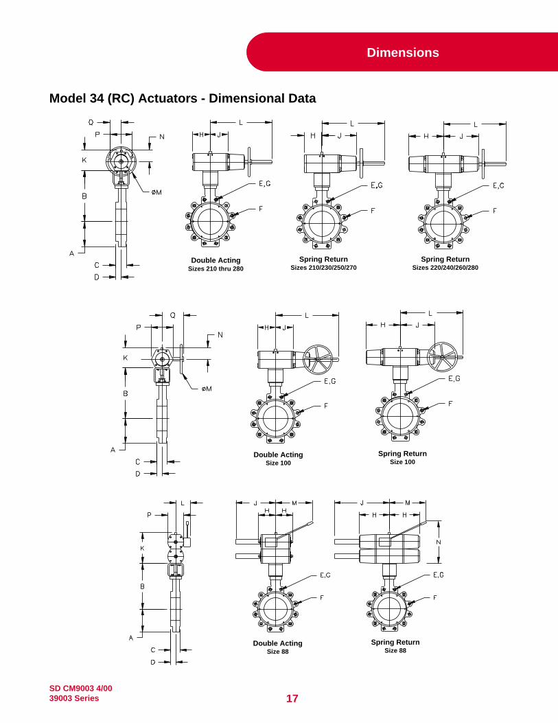
Dimensions
Model 34 (RC) Actuators - Dimensional Data
Double ActingSizes 210 thru 280
Spring ReturnSizes 210/230/250/270
Spring ReturnSizes 220/240/260/280
Double ActingSize 100
Spring ReturnSize 100
Double ActingSize 88
Spring ReturnSize 88

SD CM9003 4/0039003 Series18
Dimensions
MODEL 39003 BUTTERFLY VALVE TABLETHREAD # OF BOLT
VALVE WAFER LUG SIZE HOLES CIRCLESIZE A* A** B C D E F G**
2” 3.00 3.00 10.25 1.75 1.06 5/8-11 4 4.753” 3.00 3.38 11.00 1.92 1.20 5/8-11 4 6.004” 3.50 4.13 11.75 2.13 1.26 5/8-11 8 7.506” 4.88 5.12 13.00 2.31 1.38 3/4-10 8 9.508” 5.88 6.01 14.13 2.50 1.49 3/4-10 8 11.75
10” 6.88 7.88 14.88 2.81 1.70 7/8-9 12 14.2512” 9.50 9.50 16.63 3.23 1.86 7/8-9 12 17.0014” 11.07 11.07 17.25 3.62 2.19 1-8 12 18.7516” 12.05 12.05 22.69 4.00 2.31 1-8 16 21.2518” 13.18 13.18 24.00 4.50 2.45 1 1/8-8 16 22.7520” 13.94 13.94 25.13 5.00 2.94 1 1/8-8 20 25.0024” 16.44 16.44 27.25 6.06 3.12 1 1/4-8 20 29.5030” 22.73 22.73 34.62 6.75 3.53 1 1/4-8 28 36.0036” 32.11 32.11 38.50 8.38 4.34 1 1/2-8 32 42.7542” 35.62 35.62 44.00 9.25 5.03 1 1/2-8 36 49.5048” 38.25 38.25 47.25 10.62 5.62 1 1/2-8 44 56.002” 3.00 3.00 10.25 1.75 1.06 5/8-11 8 5.003” 3.00 3.38 11.00 1.92 1.20 3/4-10 8 6.634” 3.50 4.12 11.75 2.13 1.25 3/4-10 8 7.886” 5.12 5.50 13.00 2.29 1.38 3/4-10 12 10.638” 5.88 7.28 14.14 2.88 1.54 7/8-9 12 13.00
10” 7.38 7.88 15.38 3.25 1.70 1-8 16 15.2512” 10.50 10.50 21.00 3.62 1.86 1 1/8-8 16 17.7514” 14.57 14.57 22.38 4.62 2.48 1 1/8-8 20 20.2516” 16.32 16.32 24.00 5.25 2.59 1 1/4-8 20 22.5018” 17.26 17.26 25.13 5.88 3.03 1 1/4-8 24 24.7520” 18.49 18.49 26.39 6.31 3.24 1 1/4-8 24 27.0024” 21.67 21.67 29.38 7.19 3.62 1 1/2-8 24 32.0030” 30.50 30.50 38.88 8.88 4.39 1 3/4-8 28 39.253” 3.00 3.00 11.00 2.12 1.20 3/4-10 8 6.634” 4.62 4.62 12.00 2.50 1.40 7/8-9 8 8.506” 5.56 6.75 13.62 3.06 1.68 1-8 12 11.508” 7.38 8.03 15.13 4.00 1.85 1 1/8-8 12 13.75
10” 13.25 13.25 19.00 4.62 2.00 1 1/4-8 16 17.0012” 14.67 14.67 22.63 5.50 2.53 1 1/4-8 20 19.2516” - 18.87 30.00 7.00 3.50 1 1/2-8 20 23.75
* - Dimensions apply to wafer valves only** - Dimensions apply to lugged valves only
MODEL 33 ACTUATOR TABLE
SIZE H J K L M N P Q3” 13.00 11.50 - - - - - -4” 13.00 11.50 - - - - - -6” 17.50 15.20 - - - - - -8” 17.50 15.20 - - - - - -3” 13.00 11.50 - - - - - -4” 13.00 11.50 - - - - - -6” 17.50 15.20 - - - - - -8” 17.50 15.20 - - - - - -
MODEL 34 (RC) ACTUATOR TABLE
SIZE H J K L M N P QRC210 1.8 5.7 3.7 11.4 7.1 2.3 2.9 1.3RC220 5.7 5.7 3.7 11.4 7.1 2.3 2.9 1.3RC230 2.6 7.7 5.0 13.4 7.9 2.9 4.1 1.9RC240 7.7 7.7 5.0 13.4 7.9 2.9 4.1 1.9RC250 3.5 11.2 6.9 19.7 12.6 3.8 5.7 2.7RC260 11.2 11.2 6.9 19.7 12.6 3.8 5.7 2.7RC270 5.7 20.1 10.9 31.5 15.7 6.1 8.7 4.3RC280 20.5 20.5 10.9 31.5 23.6 6.1 8.7 4.3RC88 20.5 37.9 19.5 9.1 19.5 39.8 8.7 4.3RC100 33.5 33.5 19.0 56.0 31.5 10.7 13.8 6.9RC210 1.8 3.9 3.7 11.4 7.1 2.3 2.9 1.3RC220 3.9 3.9 3.7 11.4 7.1 2.3 2.9 1.3RC230 2.6 5.3 5.0 13.4 7.9 2.9 4.1 1.9RC240 5.3 5.3 5.0 13.4 7.9 2.9 4.1 1.9RC250 3.5 7.5 6.9 19.7 12.6 3.8 5.7 2.7RC260 7.5 7.5 6.9 19.7 12.6 3.8 5.7 2.7RC270 5.7 11.6 10.9 31.5 15.7 6.1 8.7 4.3RC280 12.2 12.2 10.9 31.5 23.6 6.1 8.7 4.3RC88 12.2 29.6 19.5 9.1 19.5 39.8 8.7 4.3RC100 20.5 20.5 19.0 56.0 31.5 10.7 13.8 6.9
Model 33 Actuator - Dimensional Data
Note: ANSI Class 150/300; Sizes 3", 4", 6" & 8" available only.
ANSI
CLA
SS 6
00
A
NSI C
LASS
300
A
NSI C
LASS
150
DOUB
LE A
CTIN
G
S
PRIN
G R
ETUR
NCL
300
CL 1
50

19SD CM9003 4/0039003 Series
7000 Electropneumatic (I/P) TransducerInput range 4-20 mA
Split rangeOutput 0.2-1 bar, adjustable
0.4-2 bar, adjustable3-15 psi, adjustable6-30 psi, adjustable
(See TS-Model 7000)
2700 Controllers (See Specification Data CW6000)
Solenoid Valves
Consult Dresser for additional Optionsand Accessories.
4700P Series Pneumatic PositionerInstrument signals 0.2-1 and 0.4-2 bar
3-15 and 6-30 psig (See Specification Data CS2007)
4700E Series Electropneumatic Positioners (See Specification Data CS2007)Input range 4-20 mA
Split range
Limit StopsNACE ComplianceOther MaterialsNon-Destructive ExaminationOxygen CleaningElectric Actuators
Options
80-4 or 80-40 Airset(See Specification Data CY7800)
77-6 or 77-60 Lockup Valve2'' Gauge 0-2 bar
496 Rotary Electric Switches(See Specification Data CS7000 E)
496-1 (1-Switch SPDT)496-2 (2-Switches SPDT)496-3 (Potentiometer Position Transmitter)496-6 (1-Switch DPDT)496-7 (2-Switches DPDT)496-8 Opto-Electronic Position Transmitter
(See Specification Data CS7050 E)
Smart Valve Interface (SVI®)Digital Positioner and Process ControllerInput range 4-20 mA
Split rangeHART Communication (See Manual EW2000)
ValVue SoftwareCalibration, Configuration, Diagnostic, andOperator Interface Tool (See Manual EW1000)
Other Limit Switches
Options and Accessories
Double Acting PositionersMoore 750P/760P Pneumatic PositionerInstrument 0.2-1 and 0.4-2 bar signals 3-15 and 6-30 psig
Moore 750E/760E Electropneumatic PositionerInput range 4-20 mA

MasoneilanSales Offices
AUSTRIADresser Valves EuropeHans Kudlich-Strasse 35A2100 Korneuburg (b. Wien), AustriaPhone: 43-2262-63689Fax: 43-2263-68915
BELGIUMDresser Valves Europe281-283 Chaussee de Bruxelles281-283 Brusselsesteenweg1190 Brussels, BelgiumPhone: 32-2-344-0970Fax: 32-2-344-1123
BRAZILDresser Industria E Comercio LtdaDivisao MasoneilanRua Senador Vergueiro, 43309521-320 Sao Caetano Do SulSao Paulo, BrazilPhone: 55-11-453-5511Fax: 55-11-453-5565
CANADAValve DivisionDresser Canada, Inc.Suite 1100333 5th Avenue S.W.Calgary, Alberta T2P 3B6CanadaPhone: 403-290-0001Fax: 403-290-1526
Valve DivisionDresser Canada, Inc.5010 North Service RoadBurlington, Ontario L7L 5R5CanadaPhone: 905-335-3529Fax: 905-336-7628
CHINADresser Valve DivisionSuite 2403, Capital Mansion6 Xinyuannan RoadChao Yang DistrictBeijing 100040ChinaPhone: 86-10-6466-1164Fax: 86-10-6466-0195
FRANCEDresser Produits IndustrielsDivision Masoneilan4 Place de Saverne92400 CourbevoieFranceMailing Address:92971 Paris La Defense CedexFrancePhone: 33-1-49-04-90-00Fax: 33-1-49-04-90-10
GERMANYDresser Valves EuropeKlein-Kollenburg-Strasse 78-8047877 Willich, GermanyMailing Address:P.O. Box 120847860 Willich, GermanyPhone: 49-2156-9189-0Fax: 49-2156-41058
INDIADresser Valve India Pvt. Ltd.305-306 “Midas” - Sahar PlazaMathurdas Vasanji RoadJ.B. Nagar - Andheri EastMumbai, India 400 059Phone: 91-22-835-4790Fax: 91-22-835-4791
ITALYDresser Italia S.p.A.Masoneilan OperationVia Cassano, 7780020 Casavatore (Naples), ItalyPhone: 39-81-7892-111Fax: 39-81-7892-208
JAPANNiigata Masoneilan Company, Ltd.20th Floor, Marive East TowerWBG 2-6 Nakase, Mihama-KuChiba-shi, Chiba 261-7120, JapanPhone: 81-43-297-9222Fax: 81-43-299-1115
KOREADresser Korea, Inc.#2107 Kuk Dong Building60-1, 3-Ka, Choongmu-roChung-Ku, Soeul - 100705KoreaPhone: 82-2-274-0792Fax: 82-2-274-0794
KUWAITDresser Valve DivisionP.O. Box 242Safat 13003, KuwaitCourier:Flat No. 36, Floor 8Gaswa Complex, MahboulaKuwaitPhone: 965-9061157
MEXICODresser Valve de MexicoHenry Ford No. 114, Esq. FultonFraccionamiento Industrial San Nicolas54030 Tlalnepantla Estado de MexicoPhone: 52-5-310-9863Fax: 52-5-310-5584
THE NETHERLANDSDresser Valves EuropeSteenhouwerstraat 113194 AG HoogvlietThe NetherlandsMailing Address:P.O. Box 640NL - 3190 AN Hoogvliet RTThe NetherlandsPhone: 31-10-438-4122Fax: 31-10-438-4443
SINGAPOREDresser Singapore Pte LtdValve Division16, Tuas Avenue 8Singapore 639231Phone: 65-861-6100Fax: 65-861-7172
SOUTH AFRICADresser Ltd, South Africa BranchValve DivisionP.O. Box 2234, 16 Edendale RoadEastleigh, Edenvale 1610Republic of South AfricaPhone: 27-11-452-1550Fax: 27-11-452-6542
SPAINMasoneilan, S.A.Zona FrancaSector M., Calle Y08040 Barcelona, SpainPhone: 34-93-223-4175Fax: 34-93-223-4754
SWITZERLANDDresser Europe saFrauentalweg 76CH-8045 Zurich, SwitzerlandMailing Address:P.O. Box 3568CH-8021 Zurich, SwitzerlandPhone: 41-1-450 28 91Fax: 41-1-450 28 95
UNITED ARAB EMIRATESDresser Valve DivisionPost Box 61302Jebel Ali Free ZoneUnited Arab EmiratesCourier:Units Nos. JAO1 + JAO2Roundabout 8Jebel Ali Free ZoneUnited Arab EmiratesPhone: 971-4-838-752Fax: 971-4-838-038
UNITED KINGDOMValve DivisionDresser U.K. LimitedTrevithick WorksGillibrands Estate, SkelmersdaleLancashire WN8 9TU, EnglandUnited KingdomPhone: 44-1695-52600Fax: 44-1695-52662
Valve DivisionU.K. Southern Sales OfficeUnit 5, Brook Business CentreCowley Mill Road, UxbridgeMiddlesex UB8 2FX, EnglandUnited KingdomPhone: 44-1895-454900Fax: 44-1895-454919
UNITED STATESNorthern RegionValve DivisionDresser Equipment Group, Inc.85 Bodwell StreetAvon, MA 02322-1190Phone: 508-586-4600Fax: 508-427-8971
Southern RegionValve DivisionDresser Equipment Group, Inc.11100 West Airport Blvd.Stafford, TX 77477-3014Phone: 281-568-2211Toll Free: 800-847-1099Fax: 281-568-1414