8
Low Pressure Turbine Bypass Valve NBSE™
| Date post: | 21-Oct-2015 |
| Category: |
Documents |
| Upload: | venkateswarlu-ala |
| View: | 3 times |
| Download: | 1 times |

Low Pressure Turbine Bypass Valve NBSE™

CC
I NB
SE™
Turb
ine B
ypass V
alve2
Good atomization at wide range of flow rates
Small-Drilled-Hole Cage technology uses frequency shifting to maximize noise attenuation
The Rugged, Compact Steam Conditioning Solution
The NBSE™ Turbine Bypass Valve by CCI is the standard turbine bypass valve
for intermediate pressure bypass systems of combined cycle power plants
and low pressure bypass systems of subcritical and supercritical steam cycles.
The design is based on proven Sulzer Valves technology, the leader in turbine
bypass for power plants for many, many years. Featuring an integrated
spring-loaded spraywater nozzle desuperheating manifold at the valve outlet,
the NBSE™ minimizes the downstream desuperheating distance making
it suitable for bypass-to-condenser applications with short pipe runs. The
contoured body shape has been designed to avoid material concentrations
and abrupt changes of wall thickness, minimizing thermal stress in the valve.
In addition, the NBSE™ is available as a combined control and safe shutoff
valve according to TRD 421.
Spring-Loaded Nozzle Desuperheating
NBSE™ desuperheating features integral spring-loaded water injection
nozzles that optimize water injection over a wide range of flow rates at low
pressures. With a rangeability of up to 50:1, the spring-loaded water injection
nozzles vary the water flow area required to achieve the fine water droplet
size needed for atomization.
The spring-loaded water injection nozzle design provides the smallest water
droplet size possible without steam assist.
Small-Drilled-Hole Cage Technology
The NBSE™ Turbine Bypass Valve uses Small-Drilled-Hole Cage (SDHC)
technology to provide system noise attenuation through frequency shifting.
Frequency shifting is a proven method of noise attenuation recognized by
ISA in Technical Standard SP75.07 and by the IEC in Technical Standard 534-
8-3.
In frequency shifting, the main flow stream is separated into hundreds of tiny
jets. The size of the jets, which are primarily based on hole size, determines
the resulting noise frequency – the smaller the size of the jet or drilled
hole, the higher the frequency which in turn produces a lower dBA level.
Small-Drilled-Hole Cage technology is well suited for intermediate pressure
combined cycle and low pressure drum boiler turbine bypass applications
requiring reliability with moderate noise performance.
Unlike traditional drilled hole cages, the SDHC trim uses over one thousand
small drilled holes spaced apart in a special pattern designed to ensure full
jet separation, structural integrity, and noise attenuation. All drilled hole
technology is not the same – large drilled holes do not shift the frequency
high enough, and improper spacing between drilled holes allows the jets to
rejoin and form larger jets after exiting the cage. The conical flow diffuser
shape limits vibration by increasing the structural strength when compared
to cylindrical cages.
For over 30 years the NBSE™ from Sulzer Valves provides high reliability and accurate control in one steam conditioning valve.
Water-injection nozzle provides smallest water droplet size possible

CC
I NB
SE™
Turb
ine B
ypass V
alve3
Highly reliable, fast, accurate pneumatic and hydraulic actuators provide superior system control.
Accurate Control and Available TRD 421 Safety Function
CCI’s long history of developing advanced technology valves and actuation
systems for severe service and safety-related applications has led to the
development of the most reliable actuation systems available today. CCI
has supplied pneumatic and hydraulic actuation systems for over 30 years
and has an extensive installed global base. In addition, if equipped with
the necessary safety control devices in combination with the CCI hydraulic
actuation system, the NBSE™ can be used as a combined control and safe
shutoff valve according to TRD 421.
The selection of pneumatic or hydraulic actuation is primarily a function of
valve design for the particular application as well as customer preference. A
comparison of the factors influencing actuator selection is given in Table 1.
Improve Plant Efficiency – Eliminate Lost Steam
During normal operation, any leakage past a turbine bypass valve means lost
revenue.
g Steam that does not go through the turbine does not generate electricity or
revenue for the plant.
g Money spent generating the steam is lost.
g Steam leaking past a valve seat could erode the seat and cause an increase
in the leakage rate and maintenance downtime.
g Steam leaking past a valve to condenser could reduce the efficiency of
the condenser by deteriorating the vacuum and raising the condenser
temperature.
The CCI NBSE™ Turbine Bypass Valve comes standard with DIN 3230, Rate 3
or ANSI/FCI 70-2 Class V Shutoff, providing dependable, repeatable, shutoff
for long periods of time with high pressure differentials. DIN 3230, Rate 1 or
MSS-SP-61 Shutoff is standard with hydraulic actuation.
Table 1: Factors Influencing Actuator Selection
etubirttAecnamrofreP rotautcAcitamuenPICC rotautcAciluardyHICC
deepSekortS )lanoitpo(dnoceS1nahTsseL,tsaF sdnoceS5.0nahTsseL,tsaFyreV
noituloseR %1nahTsseL,dooG %1.0nahTsseL,dooGyreV
tsurhT rodecnalaBrofstnemeriuqeRtsurhTsteeMsevlaVtaeSdezirusserP
decnalabnUrofstnemeriuqeRtsurhTsteeMsevlaV
ytilibaileR tsuboRdnaelbaileRyreV tsuboRdnaelbaileRyreV
tsoCtnemerucorP evisnepxenI tsoCrehgiH
tsoCnoitallatsnI evisnepxenI tsoCrehgiH
ecnanetniaM sllikSmuideMhtiW,ysaE ecnanetniaMrofsllikSrehgiHseriuqeR
stnenopmoC seirosseccAelbaileR,erusserPwoL seirosseccAnevorP,erusserPhgiH

CC
I NB
SE™
Turb
ine B
ypass V
alve4
Optimized Body Shape For Minimal Thermal Stress
Designed for cyclic operation and frequent start-ups.
No trim parts are welded or screwed into the valve body
Small Drilled-Hole-Cage Technology
Ensures low noise levels.
Spring-Loaded Spraywater Nozzle Desuperheaters
Provides superior atomization.
Mounted directly to outlet eliminating need for additional
piping sections.
Top Entry Design
Minimizes service time.
Spraywater Manifold System
Multiple attemperation injection points with single water supply source connection.
Trim H
Valve Performance Characteristics (% Cv vs. % Stroke)Valves can be characterized to accommodate a wide range of variables.
Trim S

CC
I NB
SE™
Turb
ine B
ypass V
alve5
Use this checklist to evaluate the benefits of the NBSE™ design.
1. Special needs can be accommodated. Please consult with the factory.
2. Flexible tubing is standard for the spraywater manifold system. Rigid piping manifold option is available.
3. Dump tubes available if required.

CC
I NB
SE™
Turb
ine B
ypass V
alve6
Table 2: Dimensional Information
1. All dimensions are in inches except () are in millimeters.
2. Dimension C is for a hydraulic actuator, C* is for a pneumatic actuator and C** is for a pneumatic actuator including an optional handwheel on top.
3. Buttweld per ANSI B16.25 and mating pipe schedule.
4. Valve may be installed in any orientation. The upper structure does not require additional support.
5. Flexible tubing is supplied to a single connection manifold.
125.9 (3200)
130.3 (3310)
138.3 (3515)
150.7 (3830)
165.1 (4195)
evlaVeziS
telnIepiPeziS)hcni(
teltuOepiPeziS)hcni(
A B C *C
053 "61-"21 "82-"81 17.7 (450) 29.5 (750) 88.5 (2250) 104.3 (2650)
004 "81-"41 "03-"02 )064(1.81 )068(9.33 71.2 (1810) 108.6 (2760)
005 "22-"81 "43-"42 21.6 (550) )0301(6.04 100.9 (2565) 116.7 (2965)
006 "62-"22 "24-"23 )066(0.62 )0121(6.74 113.3 (2880) 129.1 (3280)
007 "03-"62 "44-"43 )067(9.92 58.6 (1490) 127.7 (3245) 143.5 (3645)
C**

CC
I NB
SE™
Turb
ine B
ypass V
alve7
1
6
2
5
3
8
4
7
Technical specifications and materials.
Table 3: Capacity and Performance Data
1. Rangeability may vary with process conditions. Consult with factory.
2. For exact pressure/temperature rating, consult factory.
3. Electro mechanical actuator available on request.
ezisevlaV 053 004 005 006 007
)vC(Trim S Max Capacity 1416 1873 2762 4117 5758
vTrim S K 1224 1618 2386 3556 4973
noitaziretcarahCevlaV)gninepO%.svvC%(
)dradnats(raeniL
ytilibaegnaR 1 1:05otpU
ssalCffotuhS
3etaR,0323NID:citamuenPdradnatSsa)VssalCICF/ISNA(
1etaR,0323NID:ciluardyHdradnatSsa)16-PS-SSM(
epyTrotautcA 3 notsiPcitamuenPgnitcA-elbuoDciluardyHro
edoMliaFderiuqeRsadesolCronepO
rotautcAciluardyHhtiwecalPniliaF
emiTekortSdnoceS1<,dradnatSsdnoceS2<
lanoitpO
gnitaRerutarepmeTtelnIevlaV 2 )F0 111(C006otpU
gnitaRerusserPtelnIevlaV 2 )gisP1015(raB70otpU
)vC( 1114 1503 2179 3317 4665
962 1298 1883 2866 4031
Trim H Max Capacity
vTrim H K
Table 5: Recommended Desuperheating Lengths Using Spring-Loaded Nozzles
* With saturated steam, to avoid pipe erosion and liquid drop-out due to droplet impingement, bends should be avoided.
**Saturated steam conditions cannot be controlled through downstream temperature measurement. Feed-forward/enthalpy control recommended.
+ All dimensions are in feet except () are in millimeters.
Table 4: Materials
1. Alternate materials available per customer’s specific design requirements.
2. For hydraulic actuator, plug/stem material is X19CrMoVNbN111.
DRAG is a registered trademark of CCI.©2002 CCI 393 3/02 10M
Contact us at:[email protected]
Visit us online at:www.ccivalve.com
CCI World Headquarters—CaliforniaTelephone: (949) 858-1877Fax: (949) 858-187822591 Avenida EmpresaRancho Santa Margarita,California 92688 USA
CCI Switzerland formerly Sulzer ThermtecTelephone: 41 52 262 11 66Fax: 41 52 262 01 65Hegifeldstrasse 10, P.O. Box 65CH-8408 WinterthurSwitzerland
CCI KoreaTelephone: 82 31 985 9430Fax: 82 31 985 055226-17, Pungmu-DongKimpo City, Kyunggi-Do 415-070South Korea
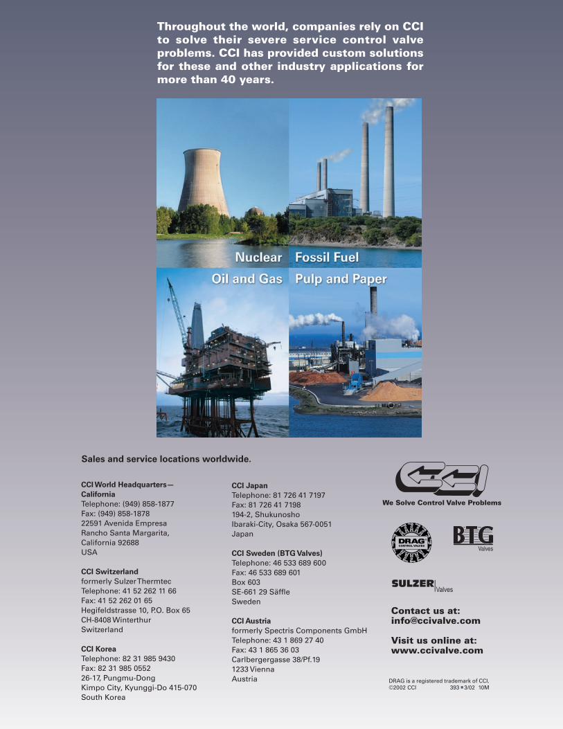
Throughout the world, companies rely on CCI to solve their severe service control valve problems. CCI has provided custom solutions for these and other industry applications for more than 40 years.
CCI JapanTelephone: 81 726 41 7197Fax: 81 726 41 7198194-2, ShukunoshoIbaraki-City, Osaka 567-0051Japan
CCI Sweden (BTG Valves)Telephone: 46 533 689 600Fax: 46 533 689 601Box 603SE-661 29 SäffleSweden
CCI Austriaformerly Spectris Components GmbHTelephone: 43 1 869 27 40 Fax: 43 1 865 36 03Carlbergergasse 38/Pf.191233 ViennaAustria
Sales and service locations worldwide.


