Aadithya V. Karthik‡, Sayak Ray, Pierluigi Nuzzo, Alan Mishchenko, Robert Brayton, and Jaijeet Roychowdhury
The Department of Electrical Engineering and Computer Sciences, The University of California, Berkeley, CA, USA‡Corresponding author. Email: [email protected]
Abstract—We present ABCD-NL, a technique that approximates non-linear
analog circuits using purely Boolean models, to high accuracy. Given ananalog/mixed-signal (AMS) system (e.g., a SPICE netlist), ABCD-NL producesa Boolean circuit representation (e.g., an And Inverter Graph, Finite StateMachine, or Binary Decision Diagram) that captures the I/O behaviour of
the given system, to near SPICE-level accuracy, without making any apriorisimplifications. The Boolean models produced by ABCD-NL can be used forhigh-speed simulation and formal verification of AMS designs, by leveragingexisting tools developed for Boolean/hybrid systems analysis (e.g., ABC [1]).
We apply ABCD-NL to a number of SPICE-level AMS circuits, including dataconverters, charge pumps, comparators, non-linear signaling/communicationssub-systems, etc. Also, we formally verify the throughput of an AMS signaling
system – modelled in SPICE using 22nm BSIM4 transistors, Booleanized withhigh accuracy using ABCD-NL, and property-checked using ABC.
I. INTRODUCTION
AMS systems are becoming increasingly important in chip design. Inrecent times, AMS blocks have become key components that limitsystem-level performance [2]. Also, AMS components now account for asignificant proportion of design bugs, designer time, and debugging cost.However, CAD tools for AMS verification have not kept pace with therapid growth in complexity of these systems.
An important challenge for AMS verification is the accurate modelling
of AMS components; because these components can introduce designflaws/loss of performance in a variety of subtle and non-obvious ways, itis important to model their behaviour at or near SPICE-level accuracy.
Fig. 1. Schematic of a typical AMS signaling/communications sub-system thatarises in signal integrity analysis.
For example, Fig. 1 depicts an AMS system that frequently arisesin Signal Integrity (SI) applications. The system consists of digitalcomponents on the transmit side (e.g., a CPU), whose outputs enter ananalog channel. The channel introduces inter-symbol interference (ISI),crosstalk, etc. The other end of the channel (the receive side) has moredigital components (e.g., a DRAM/memory controller). A key figure ofmerit of this system is its throughput, i.e., the maximum bitrate thatcan be reliably sustained. Guaranteeing the system’s throughput is a non-trivial AMS verification problem, and to issue a meaningful guarantee, itis necessary to model this system at SPICE-level accuracy.
���������� � ��
�������������� ��
� � � � � � � �� � � � � � � �
������������
���
������������� ��
���� ���� �����
���
!��
� ������ � ��
Fig. 2. Schematic of a successive approximation A/D converter (SAR-ADC).
To take another example, Fig. 2 depicts a successive approximationA/D converter (or SAR-ADC). This system contains a number of com-ponents, both analog and digital. The system’s performance (i.e., itsspeed, power consumption, etc.) is frequently limited by the analogcomponents (e.g., the speed of the DAC, the sensitivity/bandwidth of thecomparator, etc.). Therefore, to verify the SAR-ADC, it is often necessaryto model the analog components at SPICE-level accuracy (even thoughit may be sufficient to model digital components at the Boolean level).
Most existing approaches to AMS verification (e.g., [3]–[8]), however,do not model AMS components at SPICE-level accuracy. The existingapproaches are usually based on hybrid systems methods (e.g., [9]–[14]);although these methods can reason about continuous analog quantities,they tend to be limited in terms of scalability. For example, they canfail even for relatively small AMS systems consisting of just 5-10analog signals. Due to this limitation, existing verification flows usuallyadopt highly simplified “behavioural” macromodels for AMS components,which do not capture many performance-limiting analog effects (e.g., non-linear operating regions, DC offsets, ISI, distortion, etc.). As a result,AMS designers often have to carry out extensive and time-consumingSPICE simulations; this is a tedious, expensive, and error-prone process.
In an attempt to address the above concerns, a technique calledABCD-L [15] was recently proposed. ABCD-L represents linear timeinvariant (LTI) AMS components using purely Boolean models, i.e., with-out the need for any continuous variables1. ABCD-L has been shownto capture the dynamics of linear AMS components to almost SPICE-level accuracy [15]. Also, because ABCD-L models use only “cheap”Boolean variables, and not “expensive” continuous variables, the formalanalysis and verification involving these models can be very efficient,using either the state-of-the-art Boolean techniques (e.g., ABC [1]), orin conjunction with existing hybrid systems frameworks. The biggestdrawback of ABCD-L, however, is that it applies only to linear systems.Therefore, ABCD-L cannot be used for verifying systems such as thecommunications sub-system of Fig. 1, or the SAR-ADC of Fig. 2, becausethese systems are strongly non-linear.
In this paper, we propose ABCD-NL2, a new method that has all theadvantages of ABCD-L, and in addition, works for a large class of non-linear systems. Given a non-linear AMS system (e.g., a SPICE netlist),ABCD-NL produces a purely Boolean model (e.g., as a Finite State Ma-chine (FSM), an And Inverter Graph (AIG), or a Binary Decision Diagram(BDD)) that captures the dynamics of the given system to near SPICE-level accuracy. Furthermore, the Boolean model produced by ABCD-NL is well-suited for use with cutting-edge formal verification/modelchecking engines such as ABC [1], or with existing hybrid systemsframeworks. Also, the Boolean model produced by ABCD-NL can besimulated very efficiently at the logic level (without needing to solveany differential equations), so ABCD-NL can be used as a much faster,almost-as-accurate, drop-in replacement for SPICE, in many applications.
ABCD-NL requires only one condition: a DC input to the given systemshould eventually result in a DC output. This condition is satisfied byalmost all non-linear systems of interest to AMS designers, e.g., D/A andA/D converters, amplifiers and comparators, linear and non-linear filters,equalizers, switches and multiplexers, charge pumps, I/O links, etc.
In the next section (§II), we describe the core techniques underlying
1Similar ideas have also been suggested in works like [16] and [17].2Accurate Booleanization of Continuous Dynamics – Non-Linear
ABCD-NL. We then apply ABCD-NL (in §III) to a number of non-linearsystems that are of interest to AMS designers. For example, in §III-A,we Booleanize a charge pump/filter system using ABCD-NL. We alsoapply ABCD-NL to the analog components that make up the SAR-ADCof Fig. 2, such as the D/A converter (§III-C) and the comparator (§III-D).In all these cases, we show that ABCD-NL’s Boolean model faithfullyreproduces the circuit’s behaviour.
We note that the primary focus of this paper is on modelling AMS
systems for verification, as opposed to the verification itself. However,for completeness, we present (in §III-E) an example where we use theverification tool ABC [1], together with a Boolean model produced byABCD-NL, to formally verify the throughput of a communications sub-system of the type shown in Fig. 1.
II. CORE TECHNIQUE: A NEW ALGORITHM FORBOOLEANIZING NON-LINEAR ANALOG CIRCUITS
In this section, we describe the key ideas behind ABCD-NL. As outlinedin §I, ABCD-NL takes a SPICE netlist as input, and it produces as outputa purely Boolean model (e.g., an FSM) of the given circuit.
The Boolean model represents the circuit’s inputs and outputs using finitenumbers of bits. The bits returned by the model are interpreted by the useras discretized analog waveforms. The goal is to preserve the behaviourof the original circuit as closely as possible in the Boolean model.
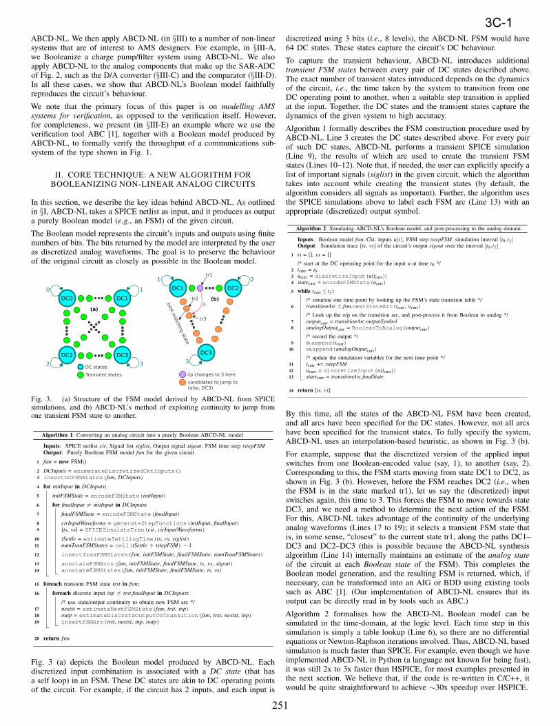
Fig. 3. (a) Structure of the FSM model derived by ABCD-NL from SPICEsimulations, and (b) ABCD-NL’s method of exploiting continuity to jump fromone transient FSM state to another.
Algorithm 1: Converting an analog circuit into a purely Boolean ABCD-NL model
Inputs: SPICE netlist cir, Signal list siglist, Output signal sigout, FSM time step tstepFSM
Output: Purely Boolean FSM model fsm for the given circuit
Fig. 3 (a) depicts the Boolean model produced by ABCD-NL. Eachdiscretized input combination is associated with a DC state (that hasa self loop) in an FSM. These DC states are akin to DC operating pointsof the circuit. For example, if the circuit has 2 inputs, and each input is
discretized using 3 bits (i.e., 8 levels), the ABCD-NL FSM would have64 DC states. These states capture the circuit’s DC behaviour.
To capture the transient behaviour, ABCD-NL introduces additionaltransient FSM states between every pair of DC states described above.The exact number of transient states introduced depends on the dynamicsof the circuit, i.e., the time taken by the system to transition from oneDC operating point to another, when a suitable step transition is appliedat the input. Together, the DC states and the transient states capture thedynamics of the given system to high accuracy.
Algorithm 1 formally describes the FSM construction procedure used byABCD-NL. Line 3 creates the DC states described above. For every pairof such DC states, ABCD-NL performs a transient SPICE simulation(Line 9), the results of which are used to create the transient FSMstates (Lines 10–12). Note that, if needed, the user can explicitly specify alist of important signals (siglist) in the given circuit, which the algorithmtakes into account while creating the transient states (by default, thealgorithm considers all signals as important). Further, the algorithm usesthe SPICE simulations above to label each FSM arc (Line 13) with anappropriate (discretized) output symbol.
Algorithm 2: Simulating ABCD-NL’s Boolean model, and post-processing to the analog domain
Inputs: Boolean model fsm, Ckt. inputs u(t), FSM step tstepFSM, simulation interval [t0, t f ]Output: Simulation trace [ts, vs] of the circuit’s output sigout over the interval [t0, t f ]
ts = [], vs = []1
/* start at the DC operating point for the input u at time t0 */tcurr = t02
ucurr = discretizeInput(u(tcurr))3
statecurr = encodeFSMState(ucurr)4
while tcurr ≤ t f :5
/* simulate one time point by looking up the FSM’s state transition table */transitionArc = fsm.nextStateArc(tcurr, ucurr)6
/* Look up the o/p on the transition arc, and post-process it from Boolean to analog */outputcurr = transitionArc.outputSymbol7
analogOutputcurr = BooleanToAnalog(outputcurr)8
/* record the output */ts.append(tcurr)9
vs.append(analogOutputcurr)10
/* update the simulation variables for the next time point */tcurr += tstepFSM11
ucurr = discretizeInput(u(tcurr))12
statecurr = transitionArc.finalState13
return [ts, vs]14
By this time, all the states of the ABCD-NL FSM have been created,and all arcs have been specified for the DC states. However, not all arcshave been specified for the transient states. To fully specify the system,ABCD-NL uses an interpolation-based heuristic, as shown in Fig. 3 (b).
For example, suppose that the discretized version of the applied inputswitches from one Boolean-encoded value (say, 1), to another (say, 2).Corresponding to this, the FSM starts moving from state DC1 to DC2, asshown in Fig. 3 (b). However, before the FSM reaches DC2 (i.e., whenthe FSM is in the state marked tr1), let us say the (discretized) inputswitches again, this time to 3. This forces the FSM to move towards stateDC3, and we need a method to determine the next action of the FSM.For this, ABCD-NL takes advantage of the continuity of the underlyinganalog waveforms (Lines 17 to 19); it selects a transient FSM state thatis, in some sense, “closest” to the current state tr1, along the paths DC1–DC3 and DC2–DC3 (this is possible because the ABCD-NL synthesisalgorithm (Line 14) internally maintains an estimate of the analog state
of the circuit at each Boolean state of the FSM). This completes theBoolean model generation, and the resulting FSM is returned, which, ifnecessary, can be transformed into an AIG or BDD using existing toolssuch as ABC [1]. (Our implementation of ABCD-NL ensures that itsoutput can be directly read in by tools such as ABC.)
Algorithm 2 formalises how the ABCD-NL Boolean model can besimulated in the time-domain, at the logic level. Each time step in thissimulation is simply a table lookup (Line 6), so there are no differentialequations or Newton-Raphson iterations involved. Thus, ABCD-NL basedsimulation is much faster than SPICE. For example, even though we haveimplemented ABCD-NL in Python (a language not known for being fast),it was still 2x to 3x faster than HSPICE, for most examples presented inthe next section. We believe that, if the code is re-written in C/C++, itwould be quite straightforward to achieve ∼30x speedup over HSPICE.
251
3C-1
III. RESULTS
We now apply ABCD-NL to circuits that are of interest to AMS designers.These include, (1) a charge pump/filter system that is relevant to PLLdesign, (2) a signaling/communications sub-system that involves (non-linear) digital logic interfacing with an analog channel, (3) a D/Aconverter, and, (4) an analog comparator, the last two circuits beingimportant analog components that make up a SAR-ADC. In each case, weshow that the Boolean model produced by ABCD-NL is able to accuratelyreproduce the SPICE-level analog dynamics of the underlying circuit,including important performance-limiting non-ideal phenomena.
A. Charge pump driving an analog filter
Fig. 4 shows a charge pump driving an analog filter, a system that playsan important role in PLLs. The system works as follows: the transistorsM1 and M2 form a current mirror that can pump a current I0 into the loadcapacitor CL, whereas transistors M3 and M4 form an opposing currentmirror that can withdraw current I0 from CL. The circuit has two inputs,Vup and Vdown. During normal operation, exactly one of these inputs ishigh; if Vup (Vdown) is high, current is pumped in (out), driving the outputvoltage Vout higher (lower); this is called the charging (discharging) modeof the charge pump, and the system responds most quickly when in oneof these modes (e.g., using a 90nm process, response times are typicallyof the order of tens of nanoseconds).
Fig. 4. Schematic of a charge pump driving an analog filter.
In addition to the normal mode of operation, it is also important to capturethe behaviour of the charge pump under anamolous inputs; for example,if both inputs are high, the charge pump enters an imbalance-driven mode,which can either charge or discharge the load, depending on operatingconditions. This type of charging/discharging is typically much slowerthan normal operation (e.g., hundreds of nanoseconds response time),because only a small current flows through the load. Finally, if bothinputs are off (cutoff mode), the output voltage, under ideal conditions,would remain constant; however, due to leakage currents and the resistiveload RL, the capacitor CL slowly discharges to a DC voltage that is almost0. The cutoff mode is the slowest mode of operation of the system, withresponse time in the microsecond range.
Since PLL performance critically depends on the non-linear chargepump/loop-filter dynamics, our goal is to use ABCD-NL to accuratelymodel the behaviour of the above system under all possible operatingconditions: charging, discharging, imbalance-driven, and cutoff. So wedesigned the system in 90nm CMOS, using BSIM4 device models. Wethen applied Algorithm 1 (of §II) to Booleanize this system (using 5 bitsto encode the output waveform), and we simulated the resulting Booleanmodel using Algorithm 2, on a range of inputs that covered all four modesof operation. In each case, we compared the output predicted by ABCD-NL’s Boolean model, against that predicted by HSPICE. Fig. 5 showsthe results, where HSPICE waveforms are shown in blue, and ABCD-NL waveforms are in green. As the figure shows, in spite of the widelydiffering time scales involved in the four modes, the Boolean modelproduced by ABCD-NL closely matches the SPICE-level dynamics ofthe system in all its modes.
Fig. 6 further demonstrates the accuracy and robustness of the Booleanmodel produced by ABCD-NL. The figure shows a long pseudo-randombit sequence applied as input to the circuit, which switches the circuit in
Fig. 5. ABCD-NL accurately captures the behaviour of the charge pump underall four modes of operation, in spite of the widely differing time scales involved.
and out of all 4 modes of operation over a long time frame. Throughoutthis time, it is seen that the Boolean model produced by ABCD-NL (thegreen waveform) closely tracks the SPICE-simulated output (the bluewaveform) of the system. This indicates that ABCD-NL is indeed apowerful and accurate modelling technique, and one that can conceivablybe used as a much faster, almost-as-accurate, drop-in replacement forSPICE over long transient runs.
B. Signaling system: Non-linear digital logic + analog channel
Fig. 7 shows a mixed-signal sub-system, of the type depicted in Fig. 1.As we mentioned in §I, such systems are often encountered in SignalIntegrity (SI) applications. In this example, the transmit side takes 3 bitsas input (A, B, and Cin), and adds them up using a full-adder, therebyproducing 2 output bits: the sum S, and the output carry Cout. These 2bits are then sent across an analog channel that consists of several RCstages, inter-linked with coupling capacitances. At the other end of thechannel, the receiver cleans the arriving waveforms Sch and Cch usingchains of inverters.
Fig. 7. A signaling/communications sub-system that arises in SI applications.
We have modelled each transistor in the above system using a22nm BSIM4 analog SPICE model (obtained from [18]). Therefore,the system above exhibits several realistic non-linear analog effects,including leakage currents, loading effects, delays, channel-inducedISI/crosstalk, etc. Our goal is to use ABCD-NL to accurately reproducethe analog waveforms at the output of the channel (Sch and Cch), in thepresence of these adverse analog effects. This is a crucial requirementfor SI analysis.
Fig. 8 shows the results obtained by applying ABCD-NL to the abovesystem. Part (a) shows three randomly generated 40-bit sequences (forA, B, and Cin, respectively), applied as inputs to the circuit. In part (b),these inputs are applied at a bitrate of 1 Gbps. At this bitrate, the systembehaves in a fairly ideal manner, i.e., distortion, crosstalk, etc. are mini-mal, as seen from the blue HSPICE waveforms Sch and Cch of Fig. 8 (b).Also, the green waveforms in the figure show the predictions made byABCD-NL’s purely Boolean model (using 4 bits to encode each outputwaveform); as the figure shows, ABCD-NL’s purely Boolean model isable to accurately predict the system’s dynamics at this bitrate.
Fig. 8 (c) shows the same bit pattern applied to the circuit, but at ahigher bitrate (3.2 Gbps). At this bitrate, the system produces considerable
252
3C-1
Fig. 6. ABCD-NL can predict the response of the charge pump/filter system, almost to SPICE-level accuracy, even over long time frames that involve rapid switchingbetween all 4 modes of operation.
Fig. 8. ABCD-NL closely matches the SPICE-level analog behaviour of thesignaling/communications sub-system of Fig. 7, at both high and low bitrates.
distortion, with significant ISI and crosstalk. Here also, it is seen from thefigure that ABCD-NL is able to accurately reproduce the analog dynamicsexhibited by the system. This demonstrates that ABCD-NL is indeed aviable modelling technique for SI applications, even when the underlyingsystem exhibits pronounced non-linear analog effects.
C. D/A converter (DAC)
Fig. 9. Schematic of a D/A converter used within a SAR-ADC.
We now apply ABCD-NL to produce a purely Boolean model of acanonical mixed-signal system, a D/A converter used within a SAR-ADC.As Fig. 9 shows, we have a 4-bit D/A converter consisting of four AnalogDevices AD8079A analog buffers (SPICE models available from [19]),and an R/2R ladder that feeds into a voltage follower.
A key figure of merit of a D/A converter is speed; so it is important to
Fig. 10. ABCD-NL closely matches SPICE-level simulation of the D/A converter,for several input bit transitions.
accurately capture the delay of the system for all possible bit transitionsat the input. Fig. 10 shows many of these transitions (due to spaceconstraints, we are unable to show all the transitions), and indeed, it canbe seen from the figure that ABCD-NL accurately captures the system’sdelay for all these inputs (using 6 bits to encode the D/A output).
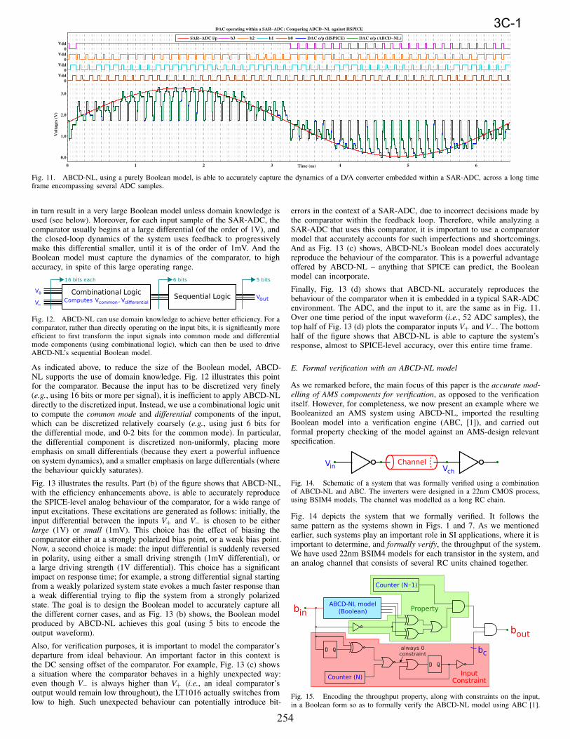
Furthermore, because our D/A converter is embedded within a SAR-ADC, it is important to have our Boolean model reproduce the system’sdynamics for input patterns that are typical to the SAR-ADC environ-ment. Fig. 11 illustrates this environment for a 4-bit SAR-ADC. The redwaveform shows a 150kHz sine wave, which is the ADC input. The ADCoperates at about 8MHz, so each period of the input generates about 52ADC samples. Over these samples, the input bits b0 to b3 of the D/Aconverter switch as shown in the top half of Fig. 11. The blue waveform atthe bottom of the figure depicts the D/A output, as predicted by HSPICE.And as seen from the green waveform, ABCD-NL is able to reproducethis response very accurately. This shows that ABCD-NL is indeed anaccurate and powerful way to Booleanize non-linear data converters foranalysing mixed-signal systems.
D. Analog comparator
We now apply ABCD-NL to an analog comparator, another key com-ponent in a SAR-ADC. For this demonstration, we shall Booleanize anoff-the-shelf comparator (LT1016 from Linear Technology, whose SPICEmodel is available online [20]), and deploy the resulting Boolean modelin a SAR-ADC environment.
Booleanizing a SAR-ADC comparator is a particularly challenging prob-lem because the circuit is highly non-linear, and very sensitive to its(large signal) inputs; for example, a differential input of 1mV elicits avery different response from the system compared to a 2mV (or 1V)differential, in terms of delay, the final steady state solution, etc. Thisnecessitates very fine discretization of the input waveforms, which can
253
3C-1
Fig. 11. ABCD-NL, using a purely Boolean model, is able to accurately capture the dynamics of a D/A converter embedded within a SAR-ADC, across a long timeframe encompassing several ADC samples.
in turn result in a very large Boolean model unless domain knowledge isused (see below). Moreover, for each input sample of the SAR-ADC, thecomparator usually begins at a large differential (of the order of 1V), andthe closed-loop dynamics of the system uses feedback to progressivelymake this differential smaller, until it is of the order of 1mV. And theBoolean model must capture the dynamics of the comparator, to highaccuracy, in spite of this large operating range.
Fig. 12. ABCD-NL can use domain knowledge to achieve better efficiency. For acomparator, rather than directly operating on the input bits, it is significantly moreefficient to first transform the input signals into common mode and differentialmode components (using combinational logic), which can then be used to driveABCD-NL’s sequential Boolean model.
As indicated above, to reduce the size of the Boolean model, ABCD-NL supports the use of domain knowledge. Fig. 12 illustrates this pointfor the comparator. Because the input has to be discretized very finely(e.g., using 16 bits or more per signal), it is inefficient to apply ABCD-NLdirectly to the discretized input. Instead, we use a combinational logic unitto compute the common mode and differential components of the input,which can be discretized relatively coarsely (e.g., using just 6 bits forthe differential mode, and 0-2 bits for the common mode). In particular,the differential component is discretized non-uniformly, placing moreemphasis on small differentials (because they exert a powerful influenceon system dynamics), and a smaller emphasis on large differentials (wherethe behaviour quickly saturates).
Fig. 13 illustrates the results. Part (b) of the figure shows that ABCD-NL,with the efficiency enhancements above, is able to accurately reproducethe SPICE-level analog behaviour of the comparator, for a wide range ofinput excitations. These excitations are generated as follows: initially, theinput differential between the inputs V+ and V− is chosen to be eitherlarge (1V) or small (1mV). This choice has the effect of biasing thecomparator either at a strongly polarized bias point, or a weak bias point.Now, a second choice is made: the input differential is suddenly reversedin polarity, using either a small driving strength (1mV differential), ora large driving strength (1V differential). This choice has a significantimpact on response time; for example, a strong differential signal startingfrom a weakly polarized system state evokes a much faster response thana weak differential trying to flip the system from a strongly polarizedstate. The goal is to design the Boolean model to accurately capture allthe different corner cases, and as Fig. 13 (b) shows, the Boolean modelproduced by ABCD-NL achieves this goal (using 5 bits to encode theoutput waveform).
Also, for verification purposes, it is important to model the comparator’sdeparture from ideal behaviour. An important factor in this context isthe DC sensing offset of the comparator. For example, Fig. 13 (c) showsa situation where the comparator behaves in a highly unexpected way:even though V− is always higher than V+ (i.e., an ideal comparator’soutput would remain low throughout), the LT1016 actually switches fromlow to high. Such unexpected behaviour can potentially introduce bit-
errors in the context of a SAR-ADC, due to incorrect decisions made bythe comparator within the feedback loop. Therefore, while analyzing aSAR-ADC that uses this comparator, it is important to use a comparatormodel that accurately accounts for such imperfections and shortcomings.And as Fig. 13 (c) shows, ABCD-NL’s Boolean model does accuratelyreproduce the behaviour of the comparator. This is a powerful advantageoffered by ABCD-NL – anything that SPICE can predict, the Booleanmodel can incorporate.
Finally, Fig. 13 (d) shows that ABCD-NL accurately reproduces thebehaviour of the comparator when it is embedded in a typical SAR-ADCenvironment. The ADC, and the input to it, are the same as in Fig. 11.Over one time period of the input waveform (i.e., 52 ADC samples), thetop half of Fig. 13 (d) plots the comparator inputs V+ and V−. The bottomhalf of the figure shows that ABCD-NL is able to capture the system’sresponse, almost to SPICE-level accuracy, over this entire time frame.
E. Formal verification with an ABCD-NL model
As we remarked before, the main focus of this paper is the accurate mod-
elling of AMS components for verification, as opposed to the verificationitself. However, for completeness, we now present an example where weBooleanized an AMS system using ABCD-NL, imported the resultingBoolean model into a verification engine (ABC, [1]), and carried outformal property checking of the model against an AMS-design relevantspecification.
Fig. 14. Schematic of a system that was formally verified using a combinationof ABCD-NL and ABC. The inverters were designed in a 22nm CMOS process,using BSIM4 models. The channel was modelled as a long RC chain.
Fig. 14 depicts the system that we formally verified. It follows thesame pattern as the systems shown in Figs. 1 and 7. As we mentionedearlier, such systems play an important role in SI applications, where it isimportant to determine, and formally verify, the throughput of the system.We have used 22nm BSIM4 models for each transistor in the system, andan analog channel that consists of several RC units chained together.
Fig. 15. Encoding the throughput property, along with constraints on the input,in a Boolean form so as to formally verify the ABCD-NL model using ABC [1].
254
3C-1
Fig. 13. ABCD-NL applied to a Linear Technology LT1016 comparator (part (a)). Part (b) shows that ABCD-NL is able to capture the dynamics of the comparatorover a wide range of differential input excitations (from 1mV all the way to 1V). Part (c) shows that ABCD-NL can duplicate the SPICE-level dynamics of thecomparator even when there is serious departure from ideal behaviour. Part (d) demonstrates that ABCD-NL is well-suited to model the comparator in the context ofa SAR-ADC.
Fig. 15 shows the verification flow that we used. As the figure shows,the Boolean circuit that is verified consists of three parts, (1) the ABCD-NL Boolean model, (2) the Boolean logic that encodes the property tobe checked, and (3) some Boolean logic to encode constraints on theinputs that can be applied to the AMS system. The circuit of Fig. 15is constructed in such a way that the given AMS design fails to meetits throughput specification if and only if the bit bout can somehow beasserted to 1 by choosing an appropriate sequence of bits applied at bin.
The constraint on the input is that it can change only once per N
clock periods of the ABCD-NL model. The time period of ABCD-NL’ssequential Boolean model is 10ps (see Algorithm 1). The input constraintis modelled using a counter that outputs a 1 every N clock cycles (Fig. 15).If this constraint is violated, the bit marked bc immediately becomes 0and stays there forever, which makes it impossible to assert bout to 1.This ensures that any counter-example returned by ABC would satisfythe input constraint.
The throughput property to be checked is that, given the above constrainton the input, the output should always reach an acceptable state beforeN clock cycles (i.e., before the input can change). This acceptable stateis defined as being ≥ 0.8V for a 1, and being ≤ 0.2V for a 0.
Fig. 16. Checking that the counter-example returned by ABCD-NL + ABC isvalid in the analog domain.
Clearly, there is an N0 such that the above throughput property will fail forall N ≤ N0. We can use ABC to quickly zero in on N0, by incorporatingABC-based verification within a binary search loop. In this way, wewere able to determine that N0 = 38. This translates to a throughputof approximately 2.56Gbps. Furthermore, we were also able to confirm,using HSPICE, that for N = 38, the counter-example returned by ABCis a valid one in the analog domain (Fig. 16). Therefore, the throughput
bound obtained is tight and meaningful. Thus, ABCD-NL is a powerfuland capable modelling technique that can be used for AMS verification.
IV. CONCLUSIONS
In conclusion, we have developed and demonstrated ABCD-NL, a newtechnique for producing purely Boolean models of non-linear analogcircuits, suitable for AMS verification. We have applied ABCD-NL toseveral circuits that are of interest to AMS designers, including chargepumps, signaling/communications sub-systems, D/A converters and com-parators used in SAR-ADCs, etc. In addition, we have demonstrated aformal verification example where we used ABCD-NL, in conjunctionwith ABC, to formally verify the throughput of an AMS system.
REFERENCES
[1] R. K. Brayton and A. Mishchenko. ABC: An academic industrial-strength verification tool. In CAV ’10: Proceedings of the
22nd International Conference on Computer Aided Verification, pages 24–40, 2010.[2] R. Parker. Analog design challenges in the new era of process scaling. At the 2012 International Workshop on Design
Automation for AMS Circuits (co-located with ICCAD).[3] W. Hartong, L. Hedrich, and E. Barke. Model checking algorithms for analog verification. In DAC ’02: Proceedings of the
39th annual ACM Design Automation Conference, pages 542–547, 2002.[4] S. Steinhorst and L. Hedrich. Model checking of analog systems using an analog specification language. In DATE ’08:
Proceedings of the ACM Conference on Design, Automation and Test in Europe, pages 324–329, 2008.[5] G. Al-Sammane, M. H. Zaki, and S. Tahar. A symbolic methodology for the verification of AMS designs. In DATE ’07:
Proceedings of the ACM Conference on Design, Automation and Test in Europe, pages 249–254, 2007.[6] S. Little. Efficient Modeling and Verification of Analog/Mixed-Signal Circuits Using Labeled Hybrid Petri Nets. PhD thesis,
University of Utah, 2008.[7] M. Althoff, A. Rajhans, B. H. Krogh, S. Yaldiz, X. Li, and L. Pileggi. Formal verification of Phase Locked Loops using
reachability analysis and continuization. In ICCAD ’10: Proceedings of the IEEE/ACM International Conference on Computer-Aided Design, pages 659–666, 2010.
[8] S. Steinhorst and L. Hedrich. Trajectory-directed discrete state space modeling for formal verification of nonlinear analogcircuits. In ICCAD ’12: Proceedings of the International Conference on Computer-Aided Design, pages 202–209, 2012.
[9] T. A. Henzinger, P. H. Ho, and H. Wong-Toi. HyTech: A model checker for hybrid systems. International Journal onSoftware Tools for Technology Transfer, 1(1):110–122, 1997.
[10] E. Asarin, T. Dang, and O. Maler. d/dt: A verification tool for hybrid systems. In CDC ’01: Proceedings of the 40th IEEEConference on Decision and Control, pages 2893–2898, 2001.
[11] A. Chutinan and B. H. Krogh. Computational techniques for hybrid system verification. IEEE Transactions on AutomaticControl, 48(1):64–75, 2003.
[12] G. Frehse. PHAVer: Algorithmic verification of hybrid systems past HyTech. International Journal on Software Tools forTechnology Transfer, 10(3):263–279, 2008.
[13] C. Tomlin, I. Mitchell, A. M. Bayen, and M. Oishi. Computational techniques for the verification of hybrid systems.Proceedings of the IEEE, 91(7):986–1001, 2003.
[14] M. Althoff, O. Stursberg, and M. Buss. Computing reachable sets of hybrid systems using a combination of zonotopes andpolytopes. Nonlinear Analysis: Hybrid Systems, 4(2):233–249, 2010.
[15] A. V. Karthik and J. Roychowdhury. ABCD-L: approximating continuous linear systems using Boolean models. In DAC
’13: Proceedings of the 50th Design Automation Conference, pages 63:1–63:9, 2013.[16] C. Gu and J. Roychowdhury. FSM model abstraction for analog/mixed-signal circuits by learning from I/O trajectories. In
ASP-DAC ’11: Proceedings of the 16th Asia and South Pacific Design Automation Conference, pages 7–12, 2011.[17] K. V. Aadithya and J. Roychowdhury. DAE2FSM: Automatic generation of accurate discrete-time logical abstractions for
continuous-time circuit dynamics. In DAC ’12: Proceedings of the 49th Design Automation Conference, pages 311–316,2012.