79
http://www.3com.com/ Baseline Switch 2250 Plus User Guide Installationsanleitung 3C16476CS Part No. 10015237 Rev. AA Published August 2006
| Date post: | 03-Apr-2018 |
| Category: |
Documents |
| Upload: | bonifasius-nainggolan |
| View: | 253 times |
| Download: | 0 times |

7/28/2019 3com Manual Switch
http://slidepdf.com/reader/full/3com-manual-switch 1/79
http://www.3com.com/
Baseline Switch 2250 Plus
User GuideInstallationsanleitung
3C16476CS
Part No. 10015237 Rev. AA
Published August 2006
7/28/2019 3com Manual Switch
http://slidepdf.com/reader/full/3com-manual-switch 2/79
7/28/2019 3com Manual Switch
http://slidepdf.com/reader/full/3com-manual-switch 3/79
CONTENTS
ABOUT THIS GUIDE
Conventions 5
Related Documentation 6
Documentation Comments 6
1 INTRODUCING THE BASELINE SWITCH
Overview of the Baseline Switch 2250 Plus 7
Features and Capabilities 7
Autosensing of MDI/MDIX Connections 7
Autonegotiating 10/100 Mbps Ports 7SFP Ports 8
Traffic Prioritization 8
Forwarding of BPDU Packets 8
Physical Features 9
Front Panel 9
Rear Panel 12
Package Contents 12
2 INSTALLING THE SWITCH
Before You Begin 13
Positioning the Switch 13
Aufstellen des Switch 14
Rack-Mounting or Free-Standing 14
Using the Mounting Kit 14
Montagesatz Anweisungen 15
Placing Units On Top of Each Other 16
Supplying Power to the Switch 16
Checking for Correct Operation 16
Connecting a Network Device 17
Using SFP Transceivers 18Approved SFP Transceivers 18
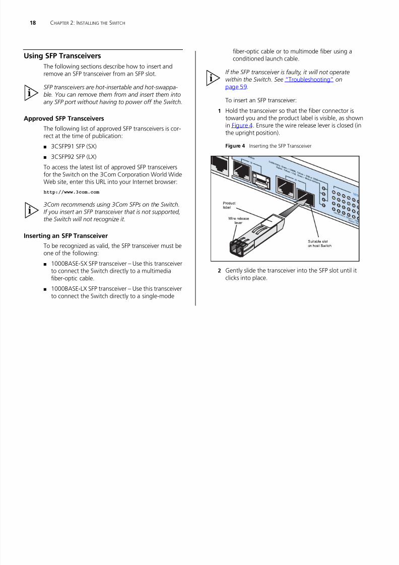
Inserting an SFP Transceiver 18
Removing an SFP Transceiver 19
Performing Spot Checks 19
3 CONNECTING TO THE WEB INTERFACE
Requirements for Accessing the Web Interface 21Running the Discovery Application 21
Logging On to the Web Interface 23
Navigating the Web Interface 23
Menu 23
Buttons 25
Accessing the Interface Without Using Discovery 26
DHCP Assigned IP Address 26
Manually Assigned (Static) IP Address 26
4 CONFIGURING THE SWITCH
Configuration Overview 27
Device Summary Information 27
Administration Settings 29
Modifying the IP Address Settings 29Automatic IP Configuration 29
IP Setup 30
7/28/2019 3com Manual Switch
http://slidepdf.com/reader/full/3com-manual-switch 4/79
Backup Configuration 30
Restore Configuration 30
Firmware Upgrade 31
Initialize 31
Reboot 32
System Access 32
System Time 34
SNMP 34
Configuring VLANs 35
VLAN 36Forwarding Tagged/Untagged Frames 39
Sample VLAN Configurations 40
Spanning Tree 41
IGMP Snooping 42
IGMP Query 42
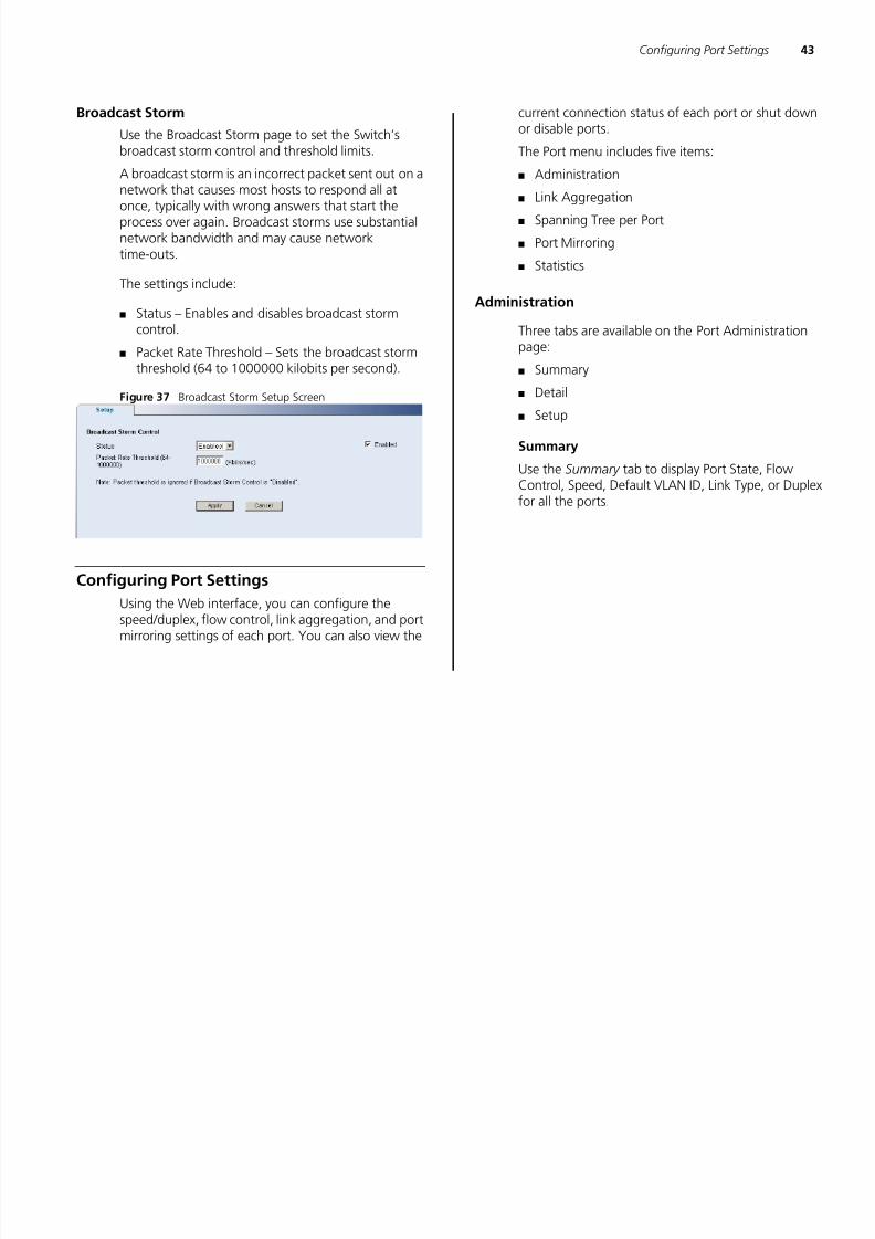
Broadcast Storm 43
Configuring Port Settings 43Administration 43
Speed/Duplex for 1000 Mbps Connections 45
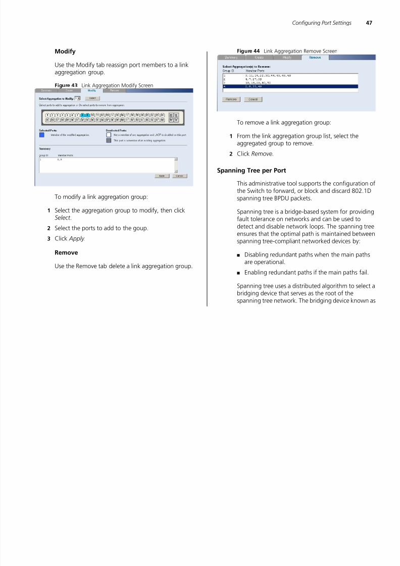
Link Aggregation 45
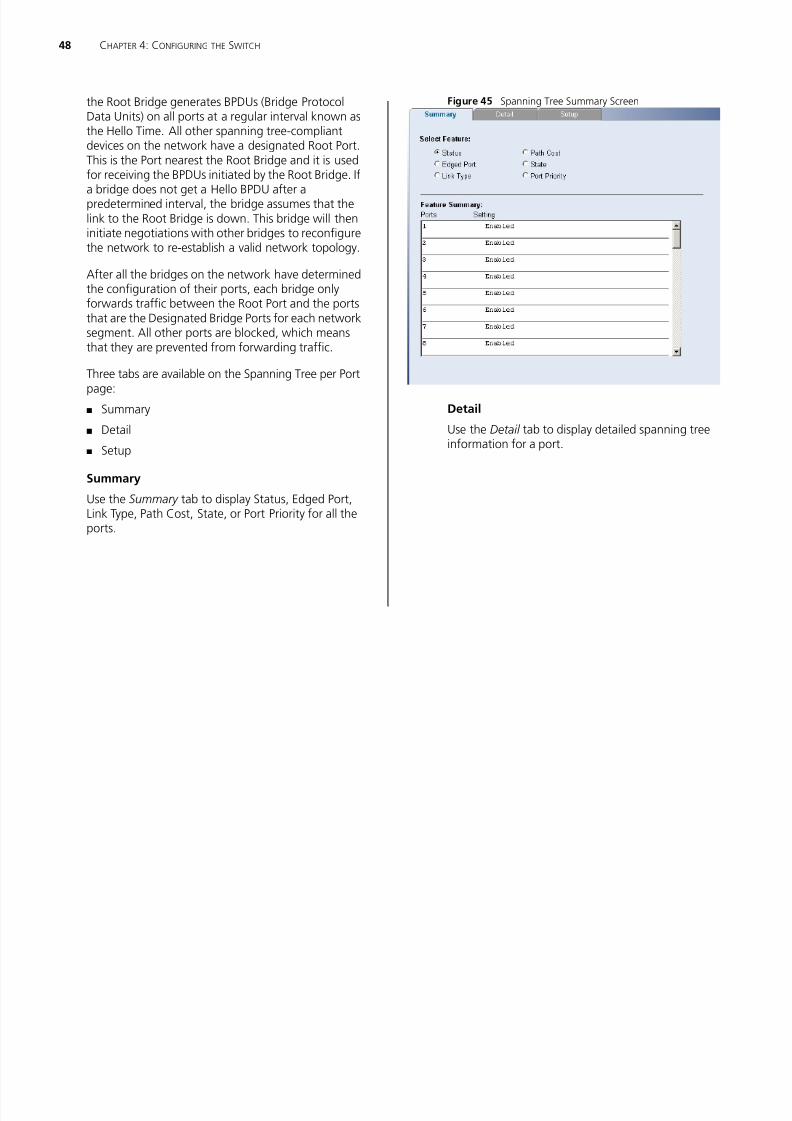
Spanning Tree per Port 47
Port Mirroring 49
QoS VoIP Traffic Settings 50
Security 53
RADIUS Client 53
802.1X Settings 54
Monitoring 56
Address Table 56
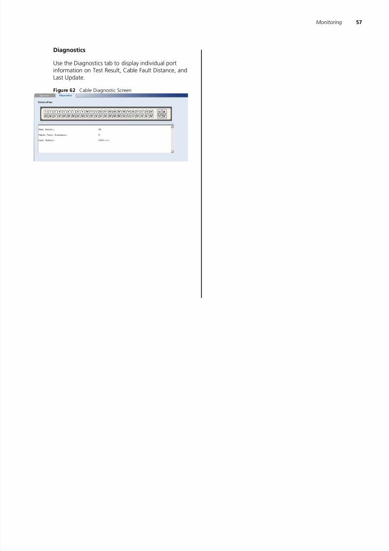
Cable Diagnostics 56
5 TROUBLESHOOTING
Resetting to Factory Defaults 59
Forgotten Password 59
Forgotten Static IP Address 60
Solving LED Issues 60
If the Problem Persists 61
A OBTAINING SUPPORT FOR YOUR PRODUCT
Register Your Product 63
Purchase Value-Added Services 63
Troubleshoot Online 63
Access Software Downloads 63
Telephone Technical Support and Repair 64
Contact Us 64
B SAFETY INFORMATION
Important Safety Information 67
C TECHNICAL INFORMATION
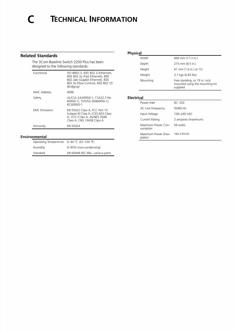
Related Standards 69
Environmental 69
Physical 69
Electrical 69
GLOSSARY
INDEX
REGULATORY NOTICES

7/28/2019 3com Manual Switch
http://slidepdf.com/reader/full/3com-manual-switch 5/79
ABOUT THIS GUIDE
This guide describes how to install your Switch andperform initial management configurations.
This guide is intended for use by network administa-
tors who are responsible for installing and setting upnetwork equipment. Consequently, it assumes a basicworking knowledge of LANs (local area networks).
Diese Anleitung ist für die Benutzung durchNetzwerkadministratoren vorgesehen, die für dieInstallation und das einstellen von Netzwerkkompo-nenten verantwortlich sind; sie setzt Erfahrung bei.
If release notes are shipped with your product and the information there differs from the information inthis guide, follow the instructions in the release notes.
Most user guides and release notes are available inAdobe Acrobat Reader Portable Document Format(PDF) on the 3Com World Wide Web site:
http://www.3com.com
Conventions
Table 1 and Table 2 list conventions that are usedthroughout this guide.
Table 1 Notice Icons
Icon Notice Type Description
Information
note
Information that describes important features
or instructions
Caution Information that alerts you to potential loss ofdata or potential damage to an application,system, or device
Warning Information that alerts you to potentialpersonal injury
Table 2 Text Conventions
Convention Description
Screen displays This typeface represents information as itappears on the screen.
The words “enter”and “type”
When you see the word “enter” in this guide,you must type something, and then pressReturn or Enter. Do not press Return or Enterwhen an instruction simply says “type.”
Words in italics Italics are used to:
■ Emphasize a point.
■ Denote a new term at the place where it isdefined in the text.
■ Identify menu names, menu commands, andsoftware button names. Examples:
From the Help menu, select Contents.
Click OK .
7/28/2019 3com Manual Switch
http://slidepdf.com/reader/full/3com-manual-switch 6/79
6 ABOUT THIS GUIDE
Related DocumentationIn addition to this guide, each 3Com Baseline Switch2250 Plus documentation set includes the following:
■ Online Help – Accessible from the Web interface,provides information that helps you perform tasksusing the Web interface.
■ Release Notes – Provide information about the
current software release, including new features,modifications, and known problems.
Documentation Comments
Your suggestions are very important to us. They willhelp make our documentation more useful to you.Please e-mail comments about this document to3Com at:
Please include the following information when con-tacting us:
■ Document title
■ Document part number (on the title page)■ Page number (if appropriate)
Example:
■ 3Com Baseline Switch 2250 Plus User Guide
■ Part number: 10015237
■ Page 25
Please note that we can only respond to comments
and questions about 3Com product documentationat this e-mail address. Questions related to technical support or sales should be directed in the first instance to your network supplier.
7/28/2019 3com Manual Switch
http://slidepdf.com/reader/full/3com-manual-switch 7/79
1 INTRODUCING THE BASELINE SWITCH
This chapter provides an overview of the features andcapabilities of the 3Com® Baseline Switch 2250 Plus.It also identifies the contents of the Switch packageand helps you get to know the physical features ofthe device.
Overview of the Baseline Switch 2250 Plus
The 3Com® Baseline Switch 2250 Plus is a versatile,easy-to-use unmanaged switch. It is ideal for userswho want the high-speed performance of 10/100
switching with the added functionality of Gigabitlinks but do not need sophisticated managementcapabilities.
The Switch is shipped ready for use. No configurationis necessary, unless you want to configure advancedfeatures such as VLAN support and link aggregation.
Features and Capabilities
The Switch has 48 shielded RJ-45, 10/100 Mbpsauto-negotiating ports and two 10/100/1000BASE-Tports that operate in conjunction with two SmallForm Factor Pluggable (SFP) transceiver slots on thefront panel. Use these SFP transceiver slots for easy,flexible connection to fiber-based Gigabit media.
While there are four physical Gigabit ports, only amaximum of two can be operational at any giventime.
Autosensing of MDI/MDIX Connections
All ports on the Switch can autosense both mediumdependent interface (MDI) and medium dependentinterface crossover (MDIX) connections. This allowsyou to connect network devices to each port usingeither a normal straight-through TP (twisted pair)cable or a ‘crossover’ TP cable.
Any port can therefore be used to connect to anotherswitch port, server, or workstation without additionalconfiguration.
Autonegotiating 10/100 Mbps Ports
Each 10/100 Mbps port automatically determines the
speed and duplex mode of the connected equipmentand provides a suitable switched connection. The1000BASE-T ports also support automatic10/100/1000 Mbps speed detection.
The 10/100 Mbps connections on these 1000BASE-Tports can operate in either half-duplex or full-duplexmode. 1000 Mbps connections, on the other hand,
only operate in full duplex mode.
7/28/2019 3com Manual Switch
http://slidepdf.com/reader/full/3com-manual-switch 8/79
7/28/2019 3com Manual Switch
http://slidepdf.com/reader/full/3com-manual-switch 9/79
Physical Features 9
available communication paths between switches and
to determine the best available path and block lessoptimal paths.
For information on configuring BPDU forwarding andblocking, refer to “Spanning Tree” on page 41.
Physical Features
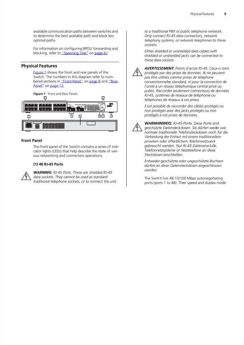
Figure 1 shows the front and rear panels of theSwitch. The numbers in this diagram refer to num-bered sections in “Front Panel” on page 9 and “RearPanel” on page 12.
Figure 1 Front and Rear Panels
Front PanelThe front panel of the Switch contains a series of indi-cator lights (LEDs) that help describe the state of vari-ous networking and connection operations.
(1) 48 RJ-45 Ports
WARNING: RJ-45 Ports. These are shielded RJ-45
data sockets. They cannot be used as standard traditional telephone sockets, or to connect the unit
to a traditional PBX or public telephone network.
Only connect RJ-45 data connectors, network telephony systems, or network telephones to these sockets.
Either shielded or unshielded data cables with shielded or unshielded jacks can be connected tothese data sockets.
AVERTISSEMENT: Points d’accès RJ-45. Ceux-ci sont
protégés par des prises de données. Ils ne peuvent pas être utilisés comme prises de téléphoneconventionnelles standard, ni pour la connection del’unité à un réseau téléphonique central privé ou public. Raccorder seulement connecteurs de donnéesRJ-45, systèmes de réseaux de téléphonie outéléphones de réseaux à ces prises.
Il est possible de raccorder des câbles protégés ounon protégés avec des jacks protégés ou non protégés à ces prises de données.
WARNHINWEIS: RJ-45-Porte. Diese Porte sind geschützte Datensteckdosen. Sie dürfen weder wienormale traditionelle Telefonsteckdosen noch für dieVerbindung der Einheit mit einem traditionellem
privatem oder öffentlichem Telefonnetzwerk gebraucht werden. Nur RJ-45-Datenanscluße,Telefonnetzsysteme or Netztelefone an dieseSteckdosen anschließen.
Entweder geschützte oder ungeschützte Buchsendürfen an diese Datensteckdosen angeschlossenwerden.
The Switch has 48 10/100 Mbps autonegotiatingports (ports 1 to 48). Their speed and duplex mode
7/28/2019 3com Manual Switch
http://slidepdf.com/reader/full/3com-manual-switch 10/79
10 CHAPTER 1: INTRODUCING THE BASELINE SWITCH
(half-duplex or full-duplex) are automatically
determined by the capabilities of the connecteddevice.
Each port also supports automatic MDI/MDI-Xdetection and can be connected to either a 10BASE-T,or a 100BASE-TX device.
CAUTION: The Switch supports full-duplex
autonegotiation. If the connected device does not support autonegotiation, the Switch will operate inhalf-duplex mode (even if the attached device isoperating in full-duplex mode).
In such a configuration, you may notice somedegradation of network performance. 3Comrecommends that you use devices that are capable of
autonegotiation (and that you ensure that autonegotiation is enabled, if it is a configurableoption). (see “Troubleshooting” on page 59 ).
(2) 10/100/1000BASE-T/SFP Ports
Ports 49 and 50 are combination Gigabit RJ-45 portswith shared Small Form Factor Pluggable (SFP) trans-ceiver slots. If an SFP transceiver (purchased sepa-
rately) is installed in a slot and is active, the associatedRJ-45 port of the same number is disabled.
The 1000BASE-T RJ-45 ports support automaticMDI/MDI-X operation, so you can usestraight-through or crossover cables for all networkconnections to workstations or servers, or to otherswitches or hubs.
The two SFP ports support fiber Gigabit Ethernet
short-wave (SX) and long-wave (LX) SFP transceiversin any combination. This offers you the flexibility ofusing SFP transceivers to provide connectivitybetween the Switch and remote 1000 Mbpsworkgroups or to create a high-capacity aggregatedlink backbone connection.
SFP ports are numbered 49 and 50 on the Switch.
When an SFP port is active, it has priority over the10/100/1000 port of the same number. Thecorresponding 10/100/1000 port is disabled when anSFP transceiver is plugged in.
(3) Link/Activity LEDs
The following tables describe the LEDs visible on thefront of the Switch, and how to read their status
according to color.
Table 4 10BASE-T/100BASE-TX Ports
Status Meaning
Green Link established, operating at 100 Mbps
Yellow Link established, operating at 10 Mbps
Flashing Green Packets are being received ortransmitted on the port at 100 Mbps

7/28/2019 3com Manual Switch
http://slidepdf.com/reader/full/3com-manual-switch 11/79
Physical Features 11
Table 5 10BASE-T/100BASE-TX/1000BASE-T Ports (4) Module Active LEDs
The Module Active LEDs show the status of any SFPmodules that are installed.
Table 6 Module Active LEDs
Flashing Yellow Packets are being received ortransmitted on the port at 10 Mbps
Off Link not established, either nothing isconnected to the port, or there is aproblem.
■ Verify that the attached device ispowered on
■ Verify that the cable or fiber is the
correct type and is not faulty■ For fiber connections, ensure that the
receive (RX) and transmit (TX) cableconnectors are not swapped
If these checks do not identify the causeof the problem, it may be that the unitor the device connected to the port isfaulty. Contact your 3Com networksupplier for further advice.
Status Meaning
Green Link established, operating at 1000Mbps
Yellow Link established, operating at 10 or 100Mbps
Flashing Green Packets are being received ortransmitted on the port at 1000 Mbps
Flashing Yellow Packets are being received ortransmitted on the port at 10 or 100Mbps
Status Meaning
Flashing Yellow toGreen
Port disabled or link loopback error
Off Link not established, either nothing isconnected to the port, or there is aproblem.
■ Verify that the attached device ispowered on
■ Verify that the cable or fiber is the
correct type and is not faulty■ For fiber connections, ensure that the
receive (RX) and transmit (TX) cableconnectors are not swapped
If these checks do not identify the causeof the problem, it may be that the unitor the device connected to the port isfaulty. Contact your 3Com networksupplier for further advice.
Status Meaning
Green Fiber SFP is inserted in the slotOff No fiber SFP is inserted in the slot
Status Meaning
7/28/2019 3com Manual Switch
http://slidepdf.com/reader/full/3com-manual-switch 12/79
12 CHAPTER 1: INTRODUCING THE BASELINE SWITCH
(5) Power LED
The Power LED shows the power status of the Switch.
Table 7 Power LED
(6) Self-Adhesive Pads
The unit is supplied with four self-adhesive rubberpads.
Do not apply the pads if you intend to rack-mount the unit.
If the unit is to be part of a free-standing stack, applythe pads to each marked corner area on theunderside of the unit. Place the unit on top of thelower unit, ensuring that the pads locate with therecesses of the lower unit.
Rear Panel
(7) Power Supply
The Switch automatically adjusts to the supply volt-age. Only use the power cord that is supplied withthe unit.
(8) Recovery Button
Use the Recovery button on the rear panel to resetthe Switch to its factory defaults. For more informa-tion, refer to “Resetting to Factory Defaults” onpage 59.
Package Contents
The 3Com Baseline Switch 2250 Plus package
includes the following items:■ One 3Com Baseline Switch 2250 Plus unit
■ One power cord
■ Four standard height, self-adhesive rubber pads
■ One mounting kit
■ One CD-ROM, which contains this User Guide and
the 3Com Discovery application
■ One warranty flyer
Before installing and using the Switch, verify that yourSwitch package has all these items. If any of theabove items are damaged or missing, contact your3Com network supplier immediately.
Status Meaning
Green The unit is powered on and ready for use
FlashingGreen
Power-on self-test is in progress
Yellow Power-on self-test or loopback test failed. If thisoccurs, reset the Switch to factory defaults. Referto “Resetting to Factory Defaults”
Off The unit is not receiving power:
■ Verify that the power cord is connected cor-rectly
■ If the unit still does not operate, contact your3Com network supplier
7/28/2019 3com Manual Switch
http://slidepdf.com/reader/full/3com-manual-switch 13/79
2 INSTALLING THE SWITCH
This chapter contains information that you need toinstall and set up the Switch. It covers the followingtopics:
■ Positioning the Switch■ Rack-Mounting or Free-Standing
■ Supplying Power to the Switch
■ Connecting a Network Device
■ Connecting a Network Device
■ Performing Spot Checks
Before You Begin
WARNING: Safety Information. Before installing or removing any components from the Switch or carry-ing out any maintenance procedures, read the safety information provided in Appendix B of this guide.
AVERTISSEMENT: Consignes de sécurité. Avant d'installer ou d'enlever tout composant du Switch oud'entamer une procédure de maintenance, lisez lesinformations relatives à la sécurité qui se trouvent dans Appendix B (l'Appendice B) de ce guide.
WARNHINWEIS: Sicherheitsinformationen. Bevor
Sie Komponenten aus dem Switch entfernen oder dem Switch hinzufuegen oder Instandhaltungsarbe-
iten verrichten, lesen Sie die Sicherheitsanweisungen,die in Appendix B (Anhang B) in diesem Handbuchaufgefuehrt sind.
Positioning the Switch
The Switch is suitable for use in an office environmentwhere it can be free-standing or mounted in a stan-dard 19-inch equipment rack.
Alternatively, the Switch can be rack-mounted in awiring closet or equipment room. A mounting kit,
containing two mounting brackets and four screws, issupplied with the Switch.
When deciding where to position the Switch, ensurethat:
■ It is accessible and cables can be connected easily.
■ Cabling is away from sources of electrical noise.These include lift shafts, microwave ovens, and airconditioning units. Electromagnetic fields caninterfere with the signals on copper cabling andintroduce errors, therefore slowing down yournetwork.
■ Water or moisture cannot enter the case of theunit.
■ Air flow around the unit and through the vents inthe side of the case is not restricted (3Com

7/28/2019 3com Manual Switch
http://slidepdf.com/reader/full/3com-manual-switch 14/79
14 CHAPTER 2: INSTALLING THE SWITCH
recommends that you provide a minimum of 25
mm or 1 in. clearance).■ The air is as free of dust as possible.
■ Temperature operating limits are not likely to beexceeded. It is recommended that the unit isinstalled in a clean, air conditioned environment.
It is always good practice to wear an anti-static wrist
strap when installing network equipment, connected to a ground point. If one is not available, try to keepin contact with a grounded rack and avoid touchingthe unit's ports and connectors, if possible. Static dis-charge can cause reliability problems in your equip-ment.
Aufstellen des SwitchBei der Entscheidung wo Sie den Switch position-ieren, stellen Sie sicher das:
■ Der Switch zugänglich ist und die Kabel leichtangeschlossen werden können.
■ Die Kabel nicht in der nähe von elektrischenStörquellen befinden. Das schließt
Aufzugsschächte, Mikrowellen und Klimaanlagenein. Elektromagnetische Felder können die Signalein den Kupferleitungen stören, und Fehlerverursachen, was die Verlangsamung IhresNetzwerkes zur Folge haben kann.
■ Weder Wasser noch Feuchtigkeit in das Gehäuseeindringen kann.
■ Die Luftzirkulation um den Switch und durch dieÖffnungen des Gehäuses nicht behindert wird.
3Com empfiehlt das Sie 25mm (1 Inch)
Zwischenraum sicherstellen.■ Die Luft so frei wie möglich von Staub ist.
■ Es unwahrscheinlich ist das die Betriebstemperaturüberschritten wird. 3Com empfiehlt das Sie denSwitch in einer sauberen, klimatisierten Umgebunginstallieren.
Rack-Mounting or Free-Standing
The unit can be mounted in a 19-inch equipment rackusing the supplied mounting kit, (see “Using theMounting Kit” on page 14), or it can be free-stand-ing. Do not place objects on top of the unit or stack.
CAUTION: If installing the Switch in a free-standing
stack of different size Baseline or SuperStack ® 3 units,the smaller units must be installed above the larger ones. Do not have a free-standing stack of more than six units.
Using the Mounting Kit
The Switch is supplied with two mounting brackets
and four screws. These are used for rack mountingthe unit. When mounting the unit, take note of theguidelines given in “Positioning the Switch” onpage 13.
The Switch is 1U (1.75 in.) high and will fit in a stan-dard 19-inch rack.
CAUTION: Before continuing, disconnect all cablesfrom the unit. Remove the self-adhesive pads fromthe underside of unit, if already fitted.
7/28/2019 3com Manual Switch
http://slidepdf.com/reader/full/3com-manual-switch 15/79
Rack-Mounting or Free-Standing 15
To rack-mount the Switch:
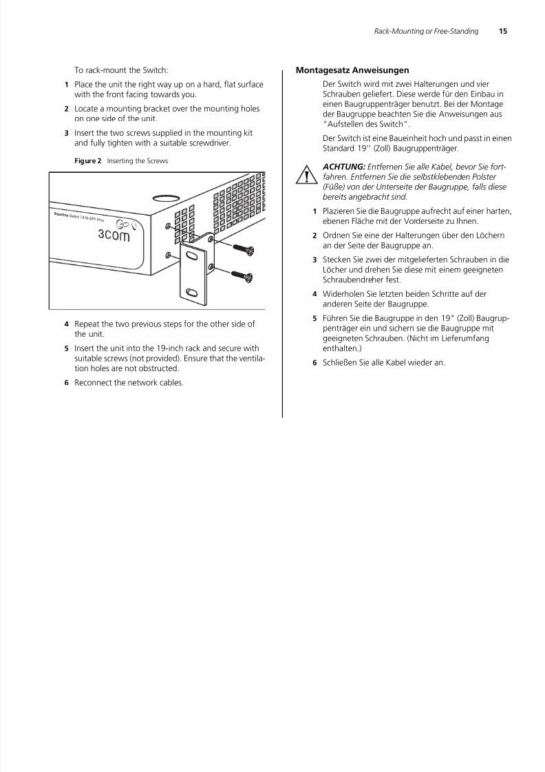
1 Place the unit the right way up on a hard, flat surfacewith the front facing towards you.
2 Locate a mounting bracket over the mounting holeson one side of the unit.
3 Insert the two screws supplied in the mounting kitand fully tighten with a suitable screwdriver.
Figure 2 Inserting the Screws
4 Repeat the two previous steps for the other side ofthe unit.
5 Insert the unit into the 19-inch rack and secure withsuitable screws (not provided). Ensure that the ventila-tion holes are not obstructed.
6 Reconnect the network cables.
Montagesatz Anweisungen
Der Switch wird mit zwei Halterungen und vierSchrauben geliefert. Diese werde für den Einbau ineinen Baugruppenträger benutzt. Bei der Montageder Baugruppe beachten Sie die Anweisungen aus“Aufstellen des Switch“.
Der Switch ist eine Baueinheit hoch und passt in einenStandard 19'' (Zoll) Baugruppenträger.
ACHTUNG: Entfernen Sie alle Kabel, bevor Sie fort-fahren. Entfernen Sie die selbstklebenden Polster (Füße) von der Unterseite der Baugruppe, falls diesebereits angebracht sind.
1 Plazieren Sie die Baugruppe aufrecht auf einer harten,ebenen Fläche mit der Vorderseite zu Ihnen.
2 Ordnen Sie eine der Halterungen über den Löchernan der Seite der Baugruppe an.
3 Stecken Sie zwei der mitgelieferten Schrauben in dieLöcher und drehen Sie diese mit einem geeignetenSchraubendreher fest.
4 Widerholen Sie letzten beiden Schritte auf deranderen Seite der Baugruppe.
5 Führen Sie die Baugruppe in den 19" (Zoll) Baugrup-penträger ein und sichern sie die Baugruppe mitgeeigneten Schrauben. (Nicht im Lieferumfangenthalten.)
6 Schließen Sie alle Kabel wieder an.
Baseline S witch 2816-SFP Plus
7/28/2019 3com Manual Switch
http://slidepdf.com/reader/full/3com-manual-switch 16/79
16 CHAPTER 2: INSTALLING THE SWITCH
Placing Units On Top of Each Other
If the Switch units are free-standing, up to four unitscan be placed one on top of the other. If you aremixing a variety of Baseline and SuperStack units, thesmaller units must be positioned at the top.
If you are placing Switch units one on top of theother, you must use the self-adhesive rubber padssupplied. Apply the pads to the underside of each
Switch, sticking one in the marked area at each cor-ner. Place the Switch units on top of each other,ensuring that the pads of the upper unit line up withthe recesses of the lower unit.
Supplying Power to the Switch
Power problems can be the cause of serious failures
and downtime in your network. Ensure that thepower input to your system is clean and free fromsags and surges to avoid unforeseen network out-ages. 3Com recommends that you install power con-ditioning, especially in areas prone to black outs,power dips and electrical storms.
The unit is intended to be grounded. Ensure it is con-
nected to earth ground during normal use. Installingproper grounding helps to avoid damage from light-ning and power surges.
Before powering on the Switch, verify that network cables and the power cable are securely connected.
CAUTION: The Switch has no ON/OFF switch; the
only method of connecting or disconnecting main
power is by connecting or disconnecting the power
cord.
To power on the Switch:
1 Plug the power cord into the power socket on therear panel of the Switch. Refer to “(7) Power Supply” on page 12 for more information.
2 Plug the other end of the power cord into a power
outlet.When the Switch is powered on, the Power LED lightsup. If the Power LED does not light up, refer to “(5)Power LED” on page 12 for more information.
Checking for Correct Operation
After you power on the Switch, it automatically per-
forms a power-on self-test (POST). During POST, thePower LED on the front panel of the Switch flashesgreen.
When POST is complete, the Power LED turns green.If the Power LED turns yellow after POST, it meansthat POST failed.
Table 8 summarizes the possible colors for the PowerLED after POST.
Table 8 Possible Power LED Colors After POST
Color State
Green The unit is powered on and ready for use
7/28/2019 3com Manual Switch
http://slidepdf.com/reader/full/3com-manual-switch 17/79
Connecting a Network Device 17
If POST fails, try the following:
■ Power off the Switch, and then power it on again.Check the Power LED and see if POST wassuccessfully completed.
■ Reset the Switch. See “Resetting to Factory
Defaults” on page 59.
CAUTION: Resetting the Switch to its factory defaultserases all your settings. You will need to reconfigurethe Switch after you reset it.
If these do not resolve the issue:
■ Check the 3Com Knowledgebase for a solution. Tovisit the 3Com Knowledgebase Web site, start yourWeb browser, and then enterhttp://knowledgebase.3com.com
■ Contact your 3Com network supplier forassistance.
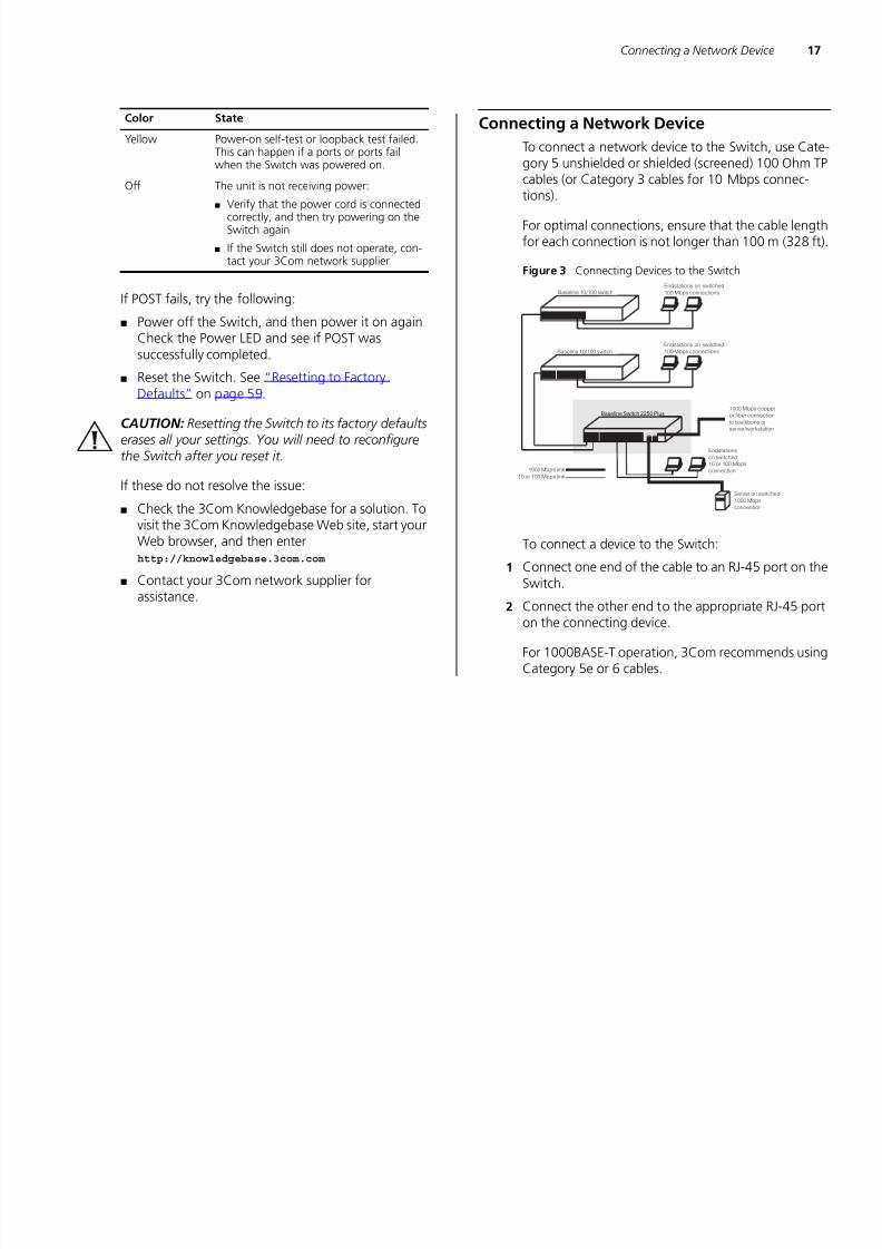
Connecting a Network Device
To connect a network device to the Switch, use Cate-gory 5 unshielded or shielded (screened) 100 Ohm TPcables (or Category 3 cables for 10 Mbps connec-tions).
For optimal connections, ensure that the cable lengthfor each connection is not longer than 100 m (328 ft).
Figure 3 Connecting Devices to the Switch
To connect a device to the Switch:
1 Connect one end of the cable to an RJ-45 port on theSwitch.
2 Connect the other end to the appropriate RJ-45 porton the connecting device.
For 1000BASE-T operation, 3Com recommends usingCategory 5e or 6 cables.
Yellow Power-on self-test or loopback test failed.This can happen if a ports or ports failwhen the Switch was powered on.
Off The unit is not receiving power:
■ Verify that the power cord is connectedcorrectly, and then try powering on theSwitch again
■ If the Switch still does not operate, con-
tact your 3Com network supplier
Color State
Baseline 10/100 switch
Endstations on switched
100 Mbps connections
Endstations on switched
100 Mbps connectionsBaseline 10/100 switch
Baseline Switch 2250 Plus
1000 Mbps link
10 or 100 Mbps link
Server on switched
1000 Mbps
connection
Endstations
on switched
10 or 100 Mbps
connection
1000 Mbps copper
or fiber connection
to backbone or
server/workstation
7/28/2019 3com Manual Switch
http://slidepdf.com/reader/full/3com-manual-switch 18/79
7/28/2019 3com Manual Switch
http://slidepdf.com/reader/full/3com-manual-switch 19/79
Performing Spot Checks 19
CAUTION: SFP transceivers are keyed and can be
properly inserted only one way. If the transceiver doesnot click when you insert it, remove it, turn it over,and then re-insert it.
3 Remove the plastic protective cover, if fitted.
4 Connect the fiber cable.
5 The transceiver connects to the network using aduplex LC connector. Attach a male duplex LC con-
nector on the network cable into the duplex LC con-nector on the transceiver.
6 Connect the other end of the cable to a device fittedwith an appropriate Gigabit Ethernet connection.
7 Check the Module Active LEDs on the front of theSwitch to ensure that it is operating correctly.
Removing an SFP Transceiver
Removing an SFP transceiver does not require power-ing off the Switch.
To remove an SFP transceiver:
1 Disconnect the cable from the transceiver.
2 Move the wire release lever downwards until it ispointing toward you.
3 Pull the wire release lever toward you to release thecatch mechanism.
The SFP transceiver should slide out easily.
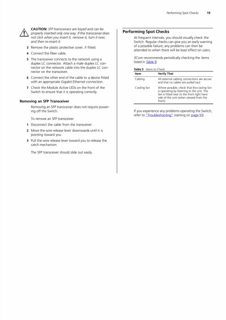
Performing Spot Checks
At frequent intervals, you should visually check theSwitch. Regular checks can give you an early warningof a possible failure; any problems can then beattended to when there will be least effect on users.
3Com recommends periodically checking the itemslisted in Table 9.
Table 9 Items to Check
If you experience any problems operating the Switch,refer to “Troubleshooting” starting on page 59.
Item Verify That
Cabling All external cabling connections are secureand that no cables are pulled taut
Cooling fan Where possible, check that the cooling fanis operating by listening to the unit. Thefan is fitted near to the front right handside of the unit (when viewed from the
front).

7/28/2019 3com Manual Switch
http://slidepdf.com/reader/full/3com-manual-switch 20/79
20 CHAPTER 2: INSTALLING THE SWITCH

7/28/2019 3com Manual Switch
http://slidepdf.com/reader/full/3com-manual-switch 21/79
3 CONNECTING TO THE WEB INTERFACE
The Switch has a built-in Web interface that you canuse to set the admin password, change the IP addressthat is assigned to the Switch, and configure itsadvanced settings.
If you only want the Switch to function as a basic layer 2 switch, you do not need to access the Webinterface and configure the Switch.
This chapter provides information on how the gainaccess to the Web interface using the Discoveryapplication. It also introduces the menu items and
buttons that are available on the Web interface.
The following topics are covered:
■ Requirements for Accessing the Web Interface
■ Running the Discovery Application
■ Logging On to the Web Interface
■ Navigating the Web Interface
Requirements for Accessing the Web Interface
To connect to the Web interface, you need thefollowing:
■ The Discovery application, which is included on3Com Baseline Switch 2250 Plus CD-ROM that issupplied with your Switch
■ A computer that is connected to the Switch andthat has a Web browser
Running the Discovery ApplicationThe 3Com Baseline Switch 2250 Plus CD-ROMcontains, among others, the Discovery application.
The Discovery application can be used for detectingand connecting to the Switch on the network. Theapplication will launch a Web interface that providesthe user with options to configure, modify, andupgrade the Switch.
To use Discovery to connect to the Web interface, dothe following:
1 On a computer that is connected to the Switch, insertthe CD-ROM into its CD drive.
Discovery should start automatically. If it does not
start automatically, go to the \Discovery folder onthe CD-ROM, and then double-click discovery.exe.

7/28/2019 3com Manual Switch
http://slidepdf.com/reader/full/3com-manual-switch 22/79
22 CHAPTER 3: CONNECTING TO THE WEB INTERFACE
The Welcome screen of Discovery appears.
Figure 5 Welcome Screen of Discovery
2 If the computer has multiple network adapters, selectthe adapter that connects the computer to theSwitch, and then click Next .
If the computer has only one adapter, click Next .
Discovery searches the network for 3Com devices.When detection is complete, the Discovered Devicesscreen displays detected network devices.
Figure 6 Discovered Devices Screen
3 On the Discovered Devices screen, click BaselineSwitch 2250 Plus, and then click Next .
The Completing the 3Com Discovery Applicationscreen appears.
4 Click Finish.
The logon dialog box for the Web interface appears.

7/28/2019 3com Manual Switch
http://slidepdf.com/reader/full/3com-manual-switch 23/79
Logging On to the Web Interface 23
Logging On to the Web Interface
After the Web interface loads in your Web browser,the first page that appears is the logon screen. Onthis screen, you need to enter the administration username and password to gain access to the Webinterface.
The logon screen also displays the IP address that the
Switch is currently using.Figure 7 Logon Dialog Box
To log on to the Web interface:
1 In User name, type admin.2 Leave the Password field blank.
3 Click OK .
Navigating the Web Interface
The Web interface has been designed to enable youto easily perform advanced configuration tasks andview information about the Switch.
Menu
The menu is located on the left side of the Webinterface. When you click an item on the menu, the
related screen appears in the main part of theinterface. Some menu items will give you sub-menutabs to choose from.
Figure 8 Switch Screen Layout
Menu
Sub-Menu Tabs
System Information

7/28/2019 3com Manual Switch
http://slidepdf.com/reader/full/3com-manual-switch 24/79
24 CHAPTER 3: CONNECTING TO THE WEB INTERFACE
Table 10 lists the available items on the menu.
Table 10 Available Menu Items
Menu Item Description
Device Summary Contains tabs that allow you to:
■ Provide a summary of the Switch’s basicsettings and versions of currentcomponents.
■ Set the polling interval in seconds.
■ Display the description for each colorcoded port.
Save Configuration Saves the Switch’s configuration.
Administration Manages the device.
IP Setup Allows you to setup, modify, or view the IPconfiguration parameters.
Backup Configuration Allows you to backup the Switch’sconfiguration.
Restore Configuration Allows you to restore a saved configuration.
Firmware Upgrade Allows you to upgrade the current firmwarevia HTTP.
Initialize Allows you to reset the Switch to factorydefault settings.
Reboot Allows you to perform system reboot.
System Access Contains tabs that allow you to:
■ Display user summary information.
■ Create a new user.
■ Modify existing users.
■ Remove existing users.
System Time Allows you to set the system time.
SNMP Contains tabs that allow you to:
■ Display SNMP summary information.
■ Enable or disable SNMP.
■ Add community strings.
■ Remove community strings.
Device Configures the device.
VLAN Contains tabs that allow you to:
■ Create a VLAN.
■ Modify a VLAN.
■ Modify VLAN membership for a port.
■ Rename a VLAN.
■ Remove a VLAN.
■ Display VLAN membership for a port.
■ Display VLAN information.
Spanning Tree Allows you to configure a Spanning TreeProtocol.
IGMP Snooping Allows you to enable or disable IGMPsnooping.
IGMP Query Allows you to enable or disable IGMP querymode.
Broadcast Storm Allows you to enable or disable rate
limiting.Port Configures the ports.
Administration Contains tabs that allow you to:
■ Display selected port information for theentire Switch.
■ Display individual port information.
■ Modify the port settings.
Menu Item Description
7/28/2019 3com Manual Switch
http://slidepdf.com/reader/full/3com-manual-switch 25/79
Navigating the Web Interface 25
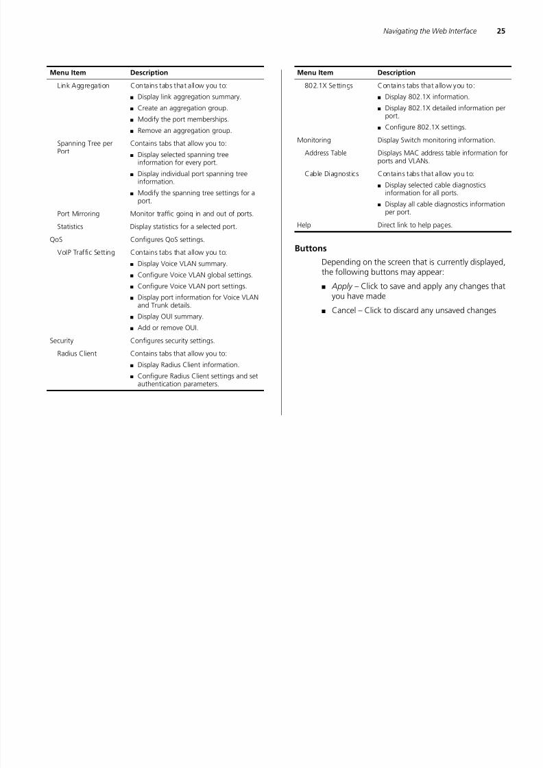
Buttons
Depending on the screen that is currently displayed,the following buttons may appear:
■ Apply – Click to save and apply any changes thatyou have made
■ Cancel – Click to discard any unsaved changes
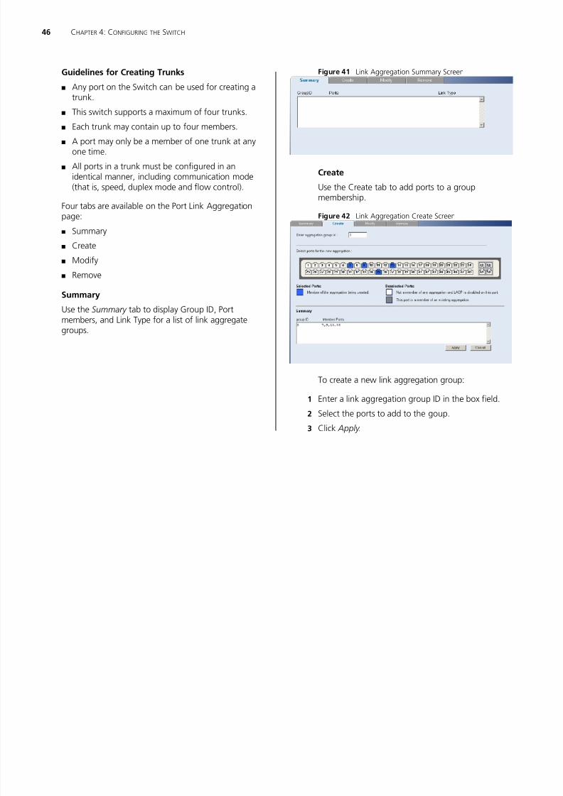
Link Aggregation Contains tabs that allow you to:
■ Display link aggregation summary.
■ Create an aggregation group.
■ Modify the port memberships.
■ Remove an aggregation group.
Spanning Tree perPort
Contains tabs that allow you to:
■ Display selected spanning tree
information for every port.■ Display individual port spanning tree
information.
■ Modify the spanning tree settings for aport.
Port Mirroring Monitor traffic going in and out of ports.
Statistics Display statistics for a selected port.
QoS Configures QoS settings.VoIP Traffic Setting Contains tabs that allow you to:
■ Display Voice VLAN summary.
■ Configure Voice VLAN global settings.
■ Configure Voice VLAN port settings.
■ Display port information for Voice VLANand Trunk details.
■
Display OUI summary.■ Add or remove OUI.
Security Configures security settings.
Radius Client Contains tabs that allow you to:
■ Display Radius Client information.
■ Configure Radius Client settings and setauthentication parameters.
Menu Item Description
802.1X Settings Contains tabs that allow you to:
■ Display 802.1X information.
■ Display 802.1X detailed information perport.
■ Configure 802.1X settings.
Monitoring Display Switch monitoring information.
Address Table Displays MAC address table information for
ports and VLANs.Cable Diagnostics Contains tabs that allow you to:
■ Display selected cable diagnosticsinformation for all ports.
■ Display all cable diagnostics informationper port.
Help Direct link to help pages.
Menu Item Description

7/28/2019 3com Manual Switch
http://slidepdf.com/reader/full/3com-manual-switch 26/79

7/28/2019 3com Manual Switch
http://slidepdf.com/reader/full/3com-manual-switch 27/79
4 CONFIGURING THE SWITCH
This chapter provides information on how toconfigure the Switch’s advanced features. Topicsinclude:
■ Device Summary Information
■ Administration Settings
■ Configuring VLANs
■ Configuring Port Settings
■ QoS VoIP Traffic Settings
■ Security
■ Monitoring
Configuration Overview
The Switch is shipped ready for use. If you only wantthe Switch to function as a basic layer 2 switch, youdo not need to access the Web interface andconfigure the Switch.
You only need to access the Web interface if youwant to:
■ Set the administration password to the Webinterface
■ Assign an IP address to the Switch
■
Configure the Switch’s advanced features■ Upgrade the firmware
Device Summary Information
The Device Summary screen, which automaticallyloads after you log on to the Web interface, provides
a snapshot of the Switch’s basic settings and versionsof current components.
Click Device Summary on the menu. A screen appearswith three tabs that include:
■ Device View
■ Polling Interval
■ Color Key
Device View
Contains fields that display the system, switch, andmanagement switch information to identify theSwitch. The fields include Product Description, SystemLocation, System Contact, Serial Number, Product 3C
Number, MAC Address, Software Version, UnitUptime, Bootroom Version, and Hardware Version.
28 CHAPTER 4 CONFIGURING THE SWITCH
7/28/2019 3com Manual Switch
http://slidepdf.com/reader/full/3com-manual-switch 28/79
28 CHAPTER 4: CONFIGURING THE SWITCH
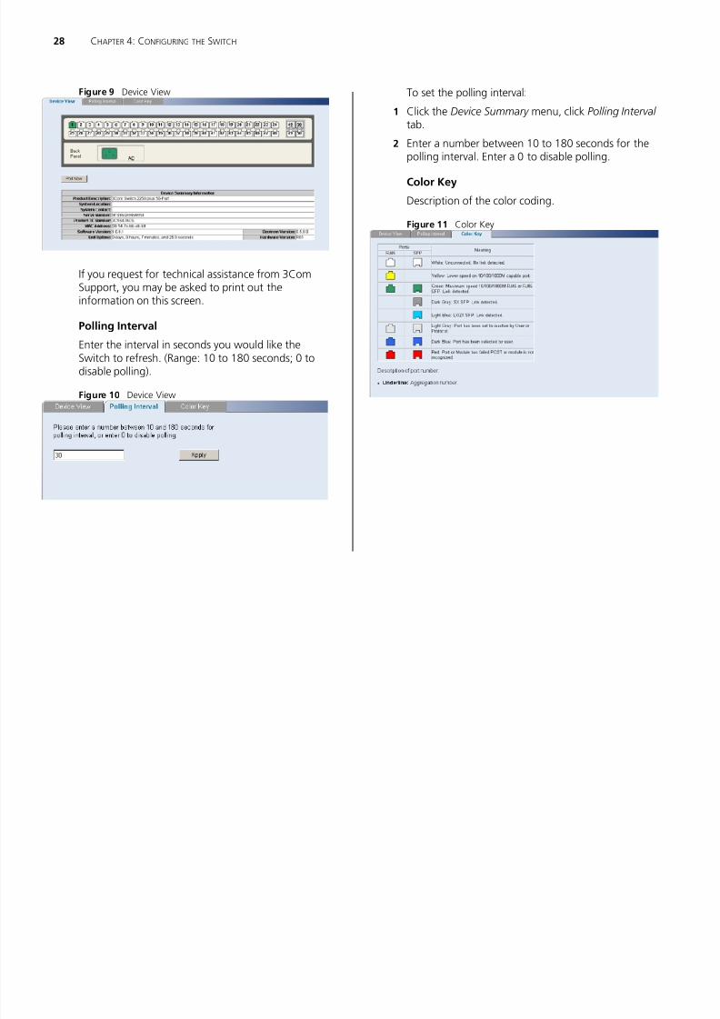
Figure 9 Device View
If you request for technical assistance from 3ComSupport, you may be asked to print out theinformation on this screen.
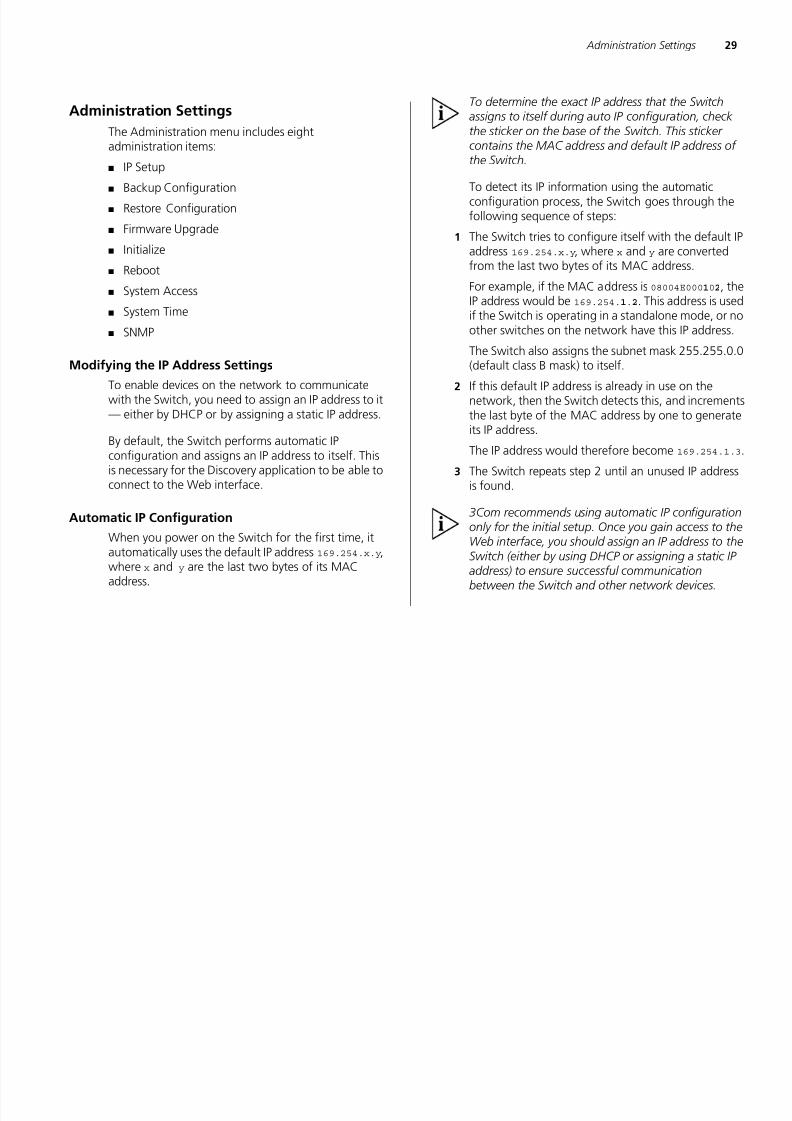
Polling Interval
Enter the interval in seconds you would like theSwitch to refresh. (Range: 10 to 180 seconds; 0 todisable polling).
Figure 10 Device View
To set the polling interval:
1 Click the Device Summary menu, click Polling Interval tab.
2 Enter a number between 10 to 180 seconds for thepolling interval. Enter a 0 to disable polling.
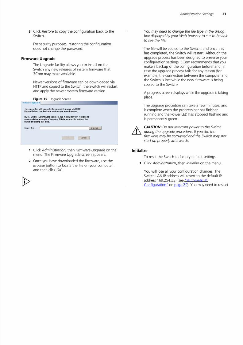
Color Key
Description of the color coding.
Figure 11 Color Key
7/28/2019 3com Manual Switch
http://slidepdf.com/reader/full/3com-manual-switch 29/79
30 CHAPTER 4: CONFIGURING THE SWITCH

7/28/2019 3com Manual Switch
http://slidepdf.com/reader/full/3com-manual-switch 30/79
30 CHAPTER 4: CONFIGURING THE SWITCH
IP Setup
To set the IP address for the Switch:1 Click Administration, then IP Setting on the menu.
The IP Settings screen appears. Follow the IP SetupWizard to complete the setup.
This wizard can also be used to set system name,location and contact information.
Figure 12 IP Settings Screen
Backup Configuration
To save the Switch configuration settings:1 Click Administration, then Backup Configuration on
the menu. The Backup Configuration screen appears.
Figure 13 Backup Configuration
2 Click OK. You will be prompted to provide a locationwhere the configuration file will be saved.
Restore ConfigurationTo reload configuration settings that you previouslysaved to a file:
1 Click Administration, then Restore Configuration onthe menu. The Restore Configuration screen appears.
Figure 14 Restore Configuration
2 Click Browse to locate the backup file on your
computer to restore the configuration settings.
Administration Settings 31
7/28/2019 3com Manual Switch
http://slidepdf.com/reader/full/3com-manual-switch 31/79
Administration Settings 31
3 Click Restore to copy the configuration back to theSwitch.
For security purposes, restoring the configurationdoes not change the password.
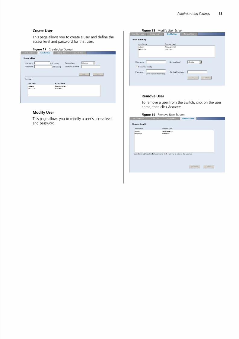
Firmware Upgrade
The Upgrade facility allows you to install on theSwitch any new releases of system firmware that
3Com may make available.
Newer versions of firmware can be downloaded viaHTTP and copied to the Switch; the Switch will restartand apply the newer system firmware version.
Figure 15 Upgrade Screen
1 Click Administration, then Firmware Upgrade on themenu. The Firmware Upgrade screen appears.
2 Once you have downloaded the firmware, use theBrowse button to locate the file on your computer,and then click OK .
You may need to change the file type in the dialogbox displayed by your Web browser to *.* to be ableto see the file.
The file will be copied to the Switch, and once thishas completed, the Switch will restart. Although theupgrade process has been designed to preserve yourconfiguration settings, 3Com recommends that youmake a backup of the configuration beforehand, incase the upgrade process fails for any reason (forexample, the connection between the computer andthe Switch is lost while the new firmware is beingcopied to the Switch).
A progress screen displays while the upgrade is takingplace.
The upgrade procedure can take a few minutes, and
is complete when the progress bar has finishedrunning and the Power LED has stopped flashing andis permanently green.
CAUTION: Do not interrupt power to the Switchduring the upgrade procedure. If you do, thefirmware may be corrupted and the Switch may not start up properly afterwards.
Initialize
To reset the Switch to factory default settings:
1 Click Administration, then Initialize on the menu.
You will lose all your configuration changes. TheSwitch LAN IP address will revert to the default IP
address 169.254.x.y. (see “Automatic IPConfiguration” on page 29). You may need to restart

7/28/2019 3com Manual Switch
http://slidepdf.com/reader/full/3com-manual-switch 32/79
7/28/2019 3com Manual Switch
http://slidepdf.com/reader/full/3com-manual-switch 33/79
34 CHAPTER 4: CONFIGURING THE SWITCH
7/28/2019 3com Manual Switch
http://slidepdf.com/reader/full/3com-manual-switch 34/79
System Time
Click Administration, then System Time on the menu.This screen allows you to set the system time. You canset the Year, Month, Day, Hours, Minutes, andSeconds.
Figure 20 System Time Screen
SNMP
Simple Network Management Protocol (SNMP) is acommunication protocol designed specifically formanaging devices on a network. Equipmentcommonly managed with SNMP includes switches,routers and host computers. SNMP is typically used toconfigure these devices for proper operation in anetwork environment, as well as to monitor them to
evaluate performance or detect potential problems.Click Administration, then SNMP on the menu. Ascreen appears with four system access tabs:
■ Summary
■ Setup
■ SNMP Add
■ SNMP Remove
Summary
Displays the list community access strings.
Figure 21 SNMP Summary Screen
Setup
Enable or disable the SNMP Agent Status.
Figure 22 SNMP Setup Screen
SNMP Add
This page allows you to create community strings formanagement access.
Configuring VLANs 35
7/28/2019 3com Manual Switch
http://slidepdf.com/reader/full/3com-manual-switch 35/79
Figure 23 SNMP Add Screen
SNMP Remove
This page allows you to remove community strings.Figure 24 SNMP Remove Screen
Configuring VLANs
A virtual LAN (VLAN) is a collection of network nodesthat share the same collision domain, regardless oftheir physical location or connection point in thenetwork. A VLAN serves as a logical workgroup withno physical barriers, and allows users to shareinformation and resources as though located on thesame LAN.
You can use the Switch to create VLANs to organizeany group of ports into separate broadcast domains.VLANs confine broadcast traffic to the originatinggroup and help eliminate broadcast storms in largenetworks. This also provides for a more secure andcleaner network environment.
You can create up to 64 VLANs, add specific ports toa chosen VLAN (so that the port can onlycommunicate with other ports on the VLAN), orconfigure a port make it a member of all VLANs.
Communication between different VLANs can onlytake place if they are all connected to a router or layer3 switch.
The Device menu includes five items:■ VLAN
■ Spanning Tree
■ IGMP Snooping
■ IGMP Query
■ Broadcast Storm
36 CHAPTER 4: CONFIGURING THE SWITCH
7/28/2019 3com Manual Switch
http://slidepdf.com/reader/full/3com-manual-switch 36/79
VLAN
Click Device, then VLAN on the menu. A screenappears with seven tabs that include:
■ Setup
■ Modify VLAN
■ Modify Port
■ Rename
■ Remove
■ Port Detail
■ VLAN Detail
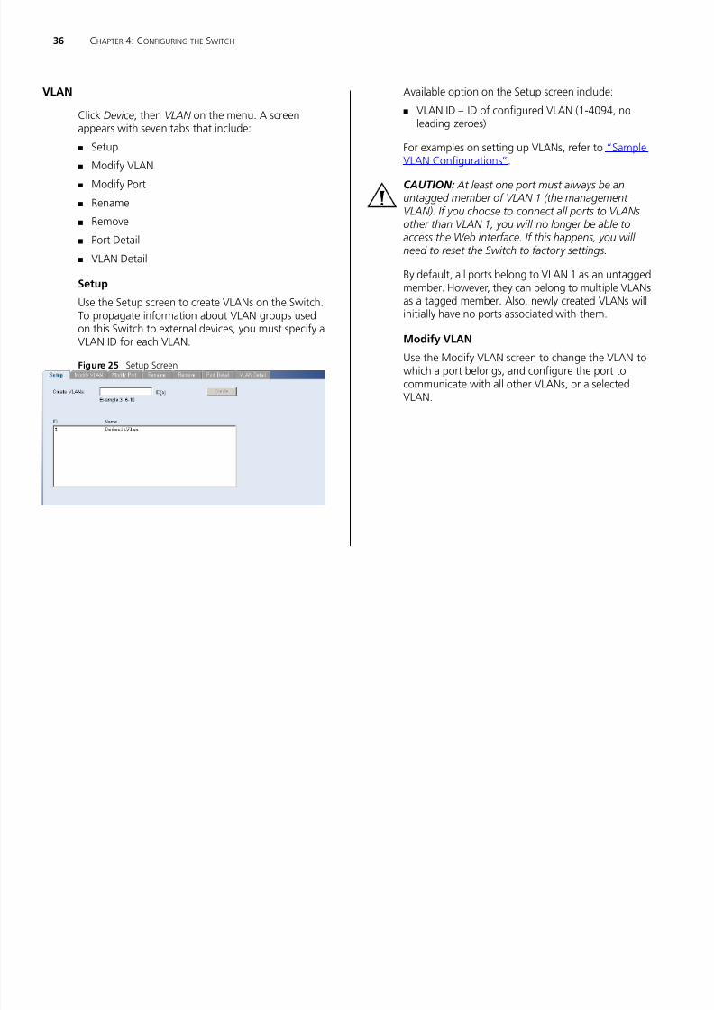
Setup
Use the Setup screen to create VLANs on the Switch.
To propagate information about VLAN groups usedon this Switch to external devices, you must specify aVLAN ID for each VLAN.
Figure 25 Setup Screen
Available option on the Setup screen include:
■ VLAN ID – ID of configured VLAN (1-4094, noleading zeroes)
For examples on setting up VLANs, refer to “SampleVLAN Configurations”.
CAUTION: At least one port must always be anuntagged member of VLAN 1 (the management
VLAN). If you choose to connect all ports to VLANsother than VLAN 1, you will no longer be able toaccess the Web interface. If this happens, you will need to reset the Switch to factory settings.
By default, all ports belong to VLAN 1 as an untaggedmember. However, they can belong to multiple VLANsas a tagged member. Also, newly created VLANs willinitially have no ports associated with them.
Modify VLAN
Use the Modify VLAN screen to change the VLAN towhich a port belongs, and configure the port tocommunicate with all other VLANs, or a selectedVLAN.
Configuring VLANs 37
7/28/2019 3com Manual Switch
http://slidepdf.com/reader/full/3com-manual-switch 37/79
Figure 26 Modify VLAN Screen
1 Enter a set of VLANs or select all VLANs to configure,
then click Select .
2 From the drop down menu, select a VLAN to modify.
3 Select a membership use. Available options for eachport include (only one option can be associated with asingle port):
■ Tagged
■ Untagged4 Select ports to associate with the membership, then
click Apply .
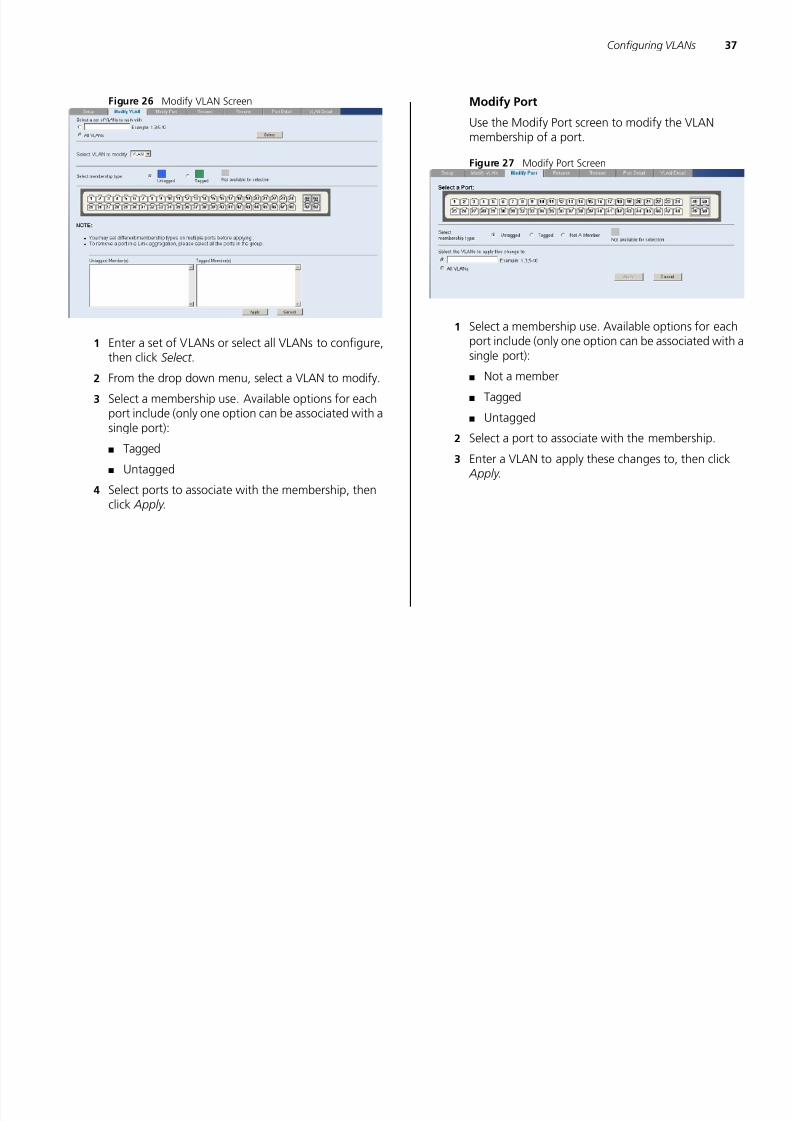
Modify Port
Use the Modify Port screen to modify the VLANmembership of a port.
Figure 27 Modify Port Screen
1 Select a membership use. Available options for eachport include (only one option can be associated with a
single port):■ Not a member
■ Tagged
■ Untagged
2 Select a port to associate with the membership.
3 Enter a VLAN to apply these changes to, then click
Apply .
38 CHAPTER 4: CONFIGURING THE SWITCH

7/28/2019 3com Manual Switch
http://slidepdf.com/reader/full/3com-manual-switch 38/79
Rename
Use the Rename screen to change the name of aVLAN.
Figure 28 Rename Screen
1 Enter a set of VLANs or select all VLANs to add to therename list, then click Select .
2 From the list of selected VLANs, choose a VLAN torename. Enter a new VLAN name and click Apply .
Remove
Use the Remove screen to remove a VLAN.Figure 29 Remove Screen
1 Enter a set of VLANs or select all VLANs to add to theremove list, then click Select .
2 From the list of selected VLANs choose a VLAN toremove, or click the Select All button to select all theVLANs. Click Remove to remove the VLAN.
Configuring VLANs 39
7/28/2019 3com Manual Switch
http://slidepdf.com/reader/full/3com-manual-switch 39/79
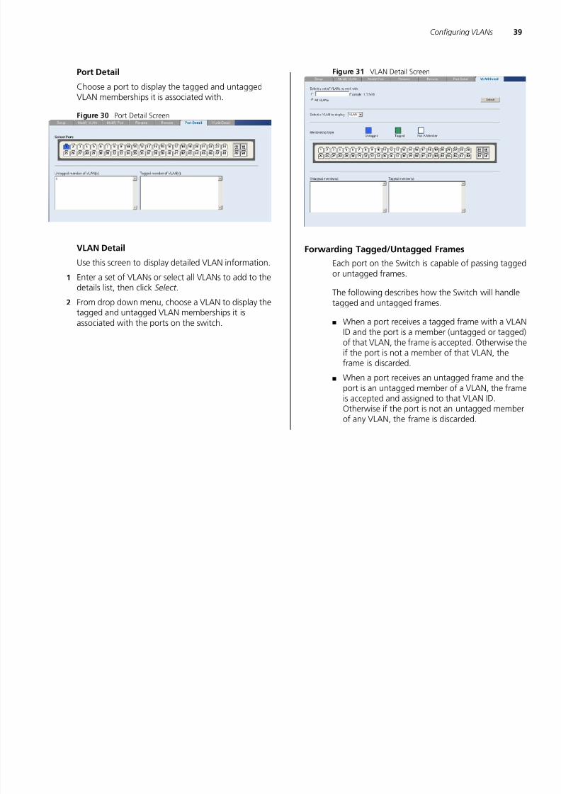
Port Detail
Choose a port to display the tagged and untaggedVLAN memberships it is associated with.
Figure 30 Port Detail Screen
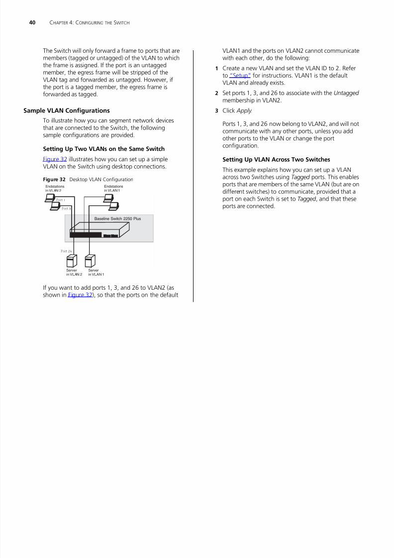
VLAN DetailUse this screen to display detailed VLAN information.
1 Enter a set of VLANs or select all VLANs to add to thedetails list, then click Select .
2 From drop down menu, choose a VLAN to display thetagged and untagged VLAN memberships it isassociated with the ports on the switch.
Figure 31 VLAN Detail Screen
Forwarding Tagged/Untagged FramesEach port on the Switch is capable of passing taggedor untagged frames.
The following describes how the Switch will handletagged and untagged frames.
■ When a port receives a tagged frame with a VLAN
ID and the port is a member (untagged or tagged)of that VLAN, the frame is accepted. Otherwise theif the port is not a member of that VLAN, theframe is discarded.
■ When a port receives an untagged frame and theport is an untagged member of a VLAN, the frameis accepted and assigned to that VLAN ID.Otherwise if the port is not an untagged memberof any VLAN, the frame is discarded.
40 CHAPTER 4: CONFIGURING THE SWITCH
7/28/2019 3com Manual Switch
http://slidepdf.com/reader/full/3com-manual-switch 40/79
The Switch will only forward a frame to ports that aremembers (tagged or untagged) of the VLAN to whichthe frame is assigned. If the port is an untaggedmember, the egress frame will be stripped of theVLAN tag and forwarded as untagged. However, ifthe port is a tagged member, the egress frame isforwarded as tagged.
Sample VLAN Configurations
To illustrate how you can segment network devicesthat are connected to the Switch, the followingsample configurations are provided.
Setting Up Two VLANs on the Same Switch
Figure 32 illustrates how you can set up a simpleVLAN on the Switch using desktop connections.
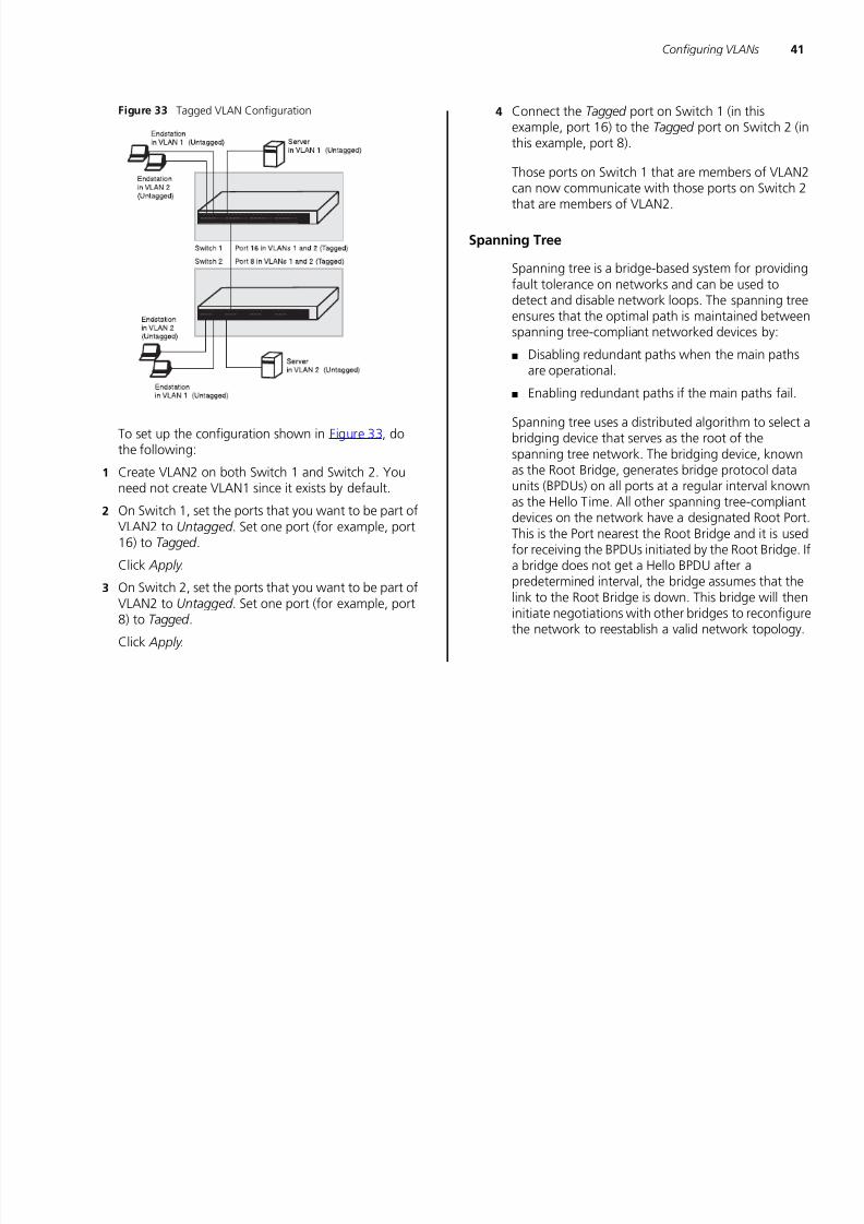
Figure 32 Desktop VLAN Configuration
If you want to add ports 1, 3, and 26 to VLAN2 (asshown in Figure 32), so that the ports on the default
VLAN1 and the ports on VLAN2 cannot communicatewith each other, do the following:
1 Create a new VLAN and set the VLAN ID to 2. Referto “Setup” for instructions. VLAN1 is the defaultVLAN and already exists.
2 Set ports 1, 3, and 26 to associate with the Untagged membership in VLAN2.
3 Click Apply .
Ports 1, 3, and 26 now belong to VLAN2, and will notcommunicate with any other ports, unless you addother ports to the VLAN or change the portconfiguration.
Setting Up VLAN Across Two Switches
This example explains how you can set up a VLAN
across two Switches using Tagged ports. This enablesports that are members of the same VLAN (but are ondifferent switches) to communicate, provided that aport on each Switch is set to Tagged , and that theseports are connected.
Baseline Switch 2250Baseline Switch 2250 Plus
Server
in VLAN 1
Endstations
in VLAN 1
Endstations
in VLAN 2
Server
in VLAN 2
Port 1
Port 3
Port 26
7/28/2019 3com Manual Switch
http://slidepdf.com/reader/full/3com-manual-switch 41/79
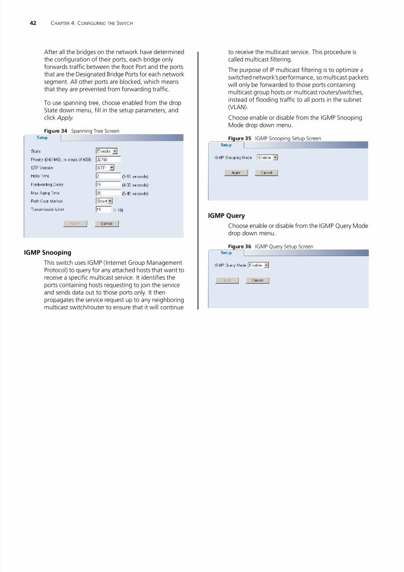
7/28/2019 3com Manual Switch
http://slidepdf.com/reader/full/3com-manual-switch 42/79
7/28/2019 3com Manual Switch
http://slidepdf.com/reader/full/3com-manual-switch 43/79
44 CHAPTER 4: CONFIGURING THE SWITCH
7/28/2019 3com Manual Switch
http://slidepdf.com/reader/full/3com-manual-switch 44/79
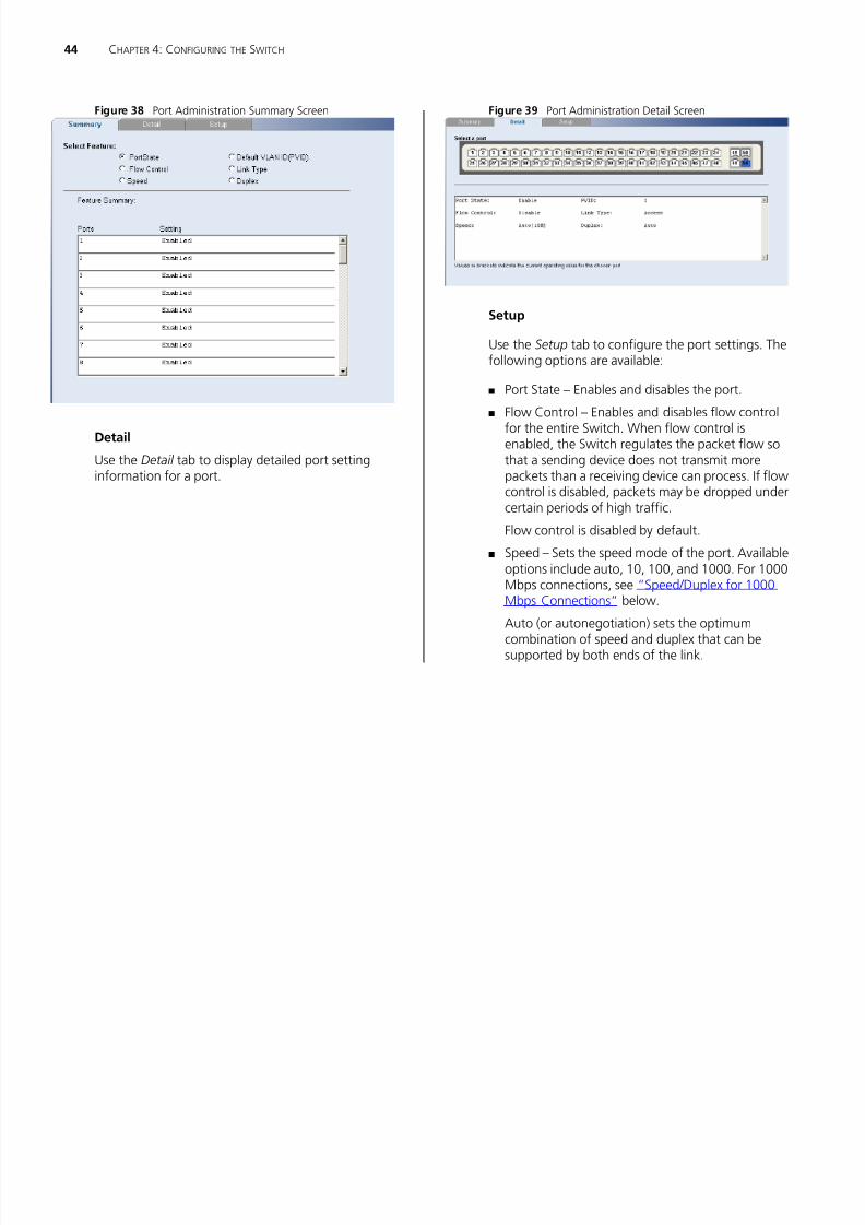
Figure 38 Port Administration Summary Screen
Detail
Use the Detail tab to display detailed port settinginformation for a port.
Figure 39 Port Administration Detail Screen
Setup
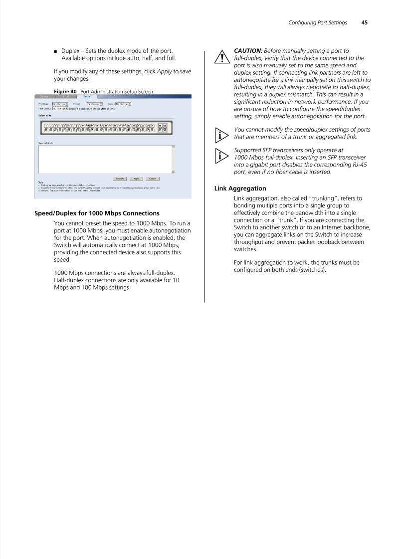
Use the Setup tab to configure the port settings. Thefollowing options are available:
■ Port State – Enables and disables the port.■ Flow Control – Enables and disables flow control
for the entire Switch. When flow control isenabled, the Switch regulates the packet flow sothat a sending device does not transmit morepackets than a receiving device can process. If flowcontrol is disabled, packets may be dropped undercertain periods of high traffic.
Flow control is disabled by default.
■ Speed – Sets the speed mode of the port. Availableoptions include auto, 10, 100, and 1000. For 1000Mbps connections, see “Speed/Duplex for 1000Mbps Connections” below.
Auto (or autonegotiation) sets the optimum
combination of speed and duplex that can besupported by both ends of the link.
7/28/2019 3com Manual Switch
http://slidepdf.com/reader/full/3com-manual-switch 45/79
7/28/2019 3com Manual Switch
http://slidepdf.com/reader/full/3com-manual-switch 46/79
7/28/2019 3com Manual Switch
http://slidepdf.com/reader/full/3com-manual-switch 47/79
7/28/2019 3com Manual Switch
http://slidepdf.com/reader/full/3com-manual-switch 48/79

7/28/2019 3com Manual Switch
http://slidepdf.com/reader/full/3com-manual-switch 49/79
50 CHAPTER 4: CONFIGURING THE SWITCH

7/28/2019 3com Manual Switch
http://slidepdf.com/reader/full/3com-manual-switch 50/79
Figure 48 Port Mirroring Screen
To set up port mirroring:
1 Connect a network analyzer to a port.
2 Access the Web interface. Click Port , then Port Mirroring on the menu. The Port Monitoring SetupScreen appears.
3 Select the port number under Monitor Port to whichyou want to monitor. Traffic to and from this port willbe forwarded to the analyser port.
4 Select the port number under Analyser Port to whichyou connected the network analyzer. Traffic to andfrom the selected mirrored ports will be forwarded tothis port.
5 Under Mirror Type, select to monitor incoming traffic,outgoing traffic, or both.
6 Click Apply .
QoS VoIP Traffic Settings
Using the Web interface, you can configure the Voiceover Internet Protocol (VoIP) settings.
The QoS VoIP Traffic Setting menu includes six tabs:
■ Summary
■ Setup
■ Port Setup
■ Port Detail
■ OUI Summary
■ OUI Modify
Summary
Use the Summary tab to display the global settings
for Voice VLAN.
Figure 49 QoS VoIP Summary Screen
QoS VoIP Traffic Settings 51

7/28/2019 3com Manual Switch
http://slidepdf.com/reader/full/3com-manual-switch 51/79
Setup
Use the Setup tab to configure the global settings forVoice VLAN. The following options are available:
■ Voice VLAN Status – Enable or disable Voice VLANfor the switch.
■ Voice VLAN ID – Input the Voice VLAN ID for theswitch.
■ Voice VLAN Aging Time – Input the aging time.
You must first create a VLAN from the VLAN Setup page before you can assign and configure a VoiceVLAN.
Figure 50 QoS VoIP Setup Screen
Port SetupUse the Port Setup tab to configure the port or trunksetting for Voice VLAN. The following options areavailable:
■ Voice VLAN Port Mode – Select between None,Manual, or Auto.
■ Voice VLAN Port Security – Enable or disable thesecurity.
To configure the Voice VLAN settings for the ports:
1 Select Voice VLAN Mode and Security settings.2 Select the ports you would like to apply these settings
to.
3 Click Apply .
Figure 51 QoS Port Setup Screen
Port Detail
Use the Port Detail tab to display the Voice VLANinformation for selected ports.

7/28/2019 3com Manual Switch
http://slidepdf.com/reader/full/3com-manual-switch 52/79
Security 53

7/28/2019 3com Manual Switch
http://slidepdf.com/reader/full/3com-manual-switch 53/79
Security
Using the Web interface, you can configure theRADIUS Client and 802.1X settings.
The Security menu includes two items:
■ RADIUS Client
■ 802.1X Settings
RADIUS Client
Remote Authentication Dial-in User Service (RADIUS)is a logon authentication protocol that uses softwarerunning on a central server to control access toRADIUS-aware devices on the network. Anauthentication server contains a database of multipleuser name/password pairs with associated privilege
levels for each user or group that requiremanagement access to a switch.
The RADIUS Client menu includes two tabs:
■ Detail
■ Configure
Detail
Use the Detail tab to display the RADIUS Clientsettings.
Figure 55 RADIUS Client Detail Screen
Configure
Use the Configure tab to configure the RADIUSsettings. The following parameters are available:
■ Max Retries – Sets the number of retries of sendingauthentication requests.
■ Timeout – Sets the interval between sendingauthentication requests.
■ IP Address – The IP address of the RADIUS server.
■ UDP port – The RADIUS server UDP port used forauthentication messages.
■ Key – Sets the RADIUS encryption key.
After you have filled in the parameters, click Apply tosave your changes.

7/28/2019 3com Manual Switch
http://slidepdf.com/reader/full/3com-manual-switch 54/79
Security 55

7/28/2019 3com Manual Switch
http://slidepdf.com/reader/full/3com-manual-switch 55/79
Setup
Use the Setup tab to configure the 802.1Xauthenticaion settings. The following fields areavailable:
■ System Authentication – Sets the global setting for802.1X. (Default: Disabled)
■ Operation Mode – Allows single or multiple hosts(clients) to connect to an 802.1X-authorized port.(Options: Single-Host, Multi-Host; Default:Single-Host)
■ Mode – Sets the authentication mode to one ofthe following options:
■ Auto – Requires a dot1x-aware client to beauthorized by the authentication server. Clientsthat are not dot1x-aware will be denied access.
■ Force-Authorized – Forces the port to grantaccess to all clients, either dot1x-aware orotherwise.
■ Force-Unauthorized – Forces the port to denyaccess to all clients, either dot1x-aware orotherwise.
■ Maximum Request – Sets the maximum number of
times the switch port will retransmit an EAPrequest packet to the client before it times out theauthentication session. (Range: 1-10; Default 2)
■ Mode Reauthentication – Sets the client to bere-authenticated after the interval specified by theRe-authentication Period. Re-authentication can beused to detect if a new device is plugged into aswitch port. (Default: Disabled)
■ Max Count – The maximum number of hosts thatcan connect to a port when the Multi-Host
operation mode is selected. (Range: 1-1024;Default: 5)
■ Reauthentication Period – Sets the time periodafter which a connected client must bere-authenticated. (Range: 1-65535 seconds;Default: 3600 seconds)
■ Quiet Period – Sets the time that a switch port
waits after the Max Request Count has beenexceeded before attempting to acquire a newclient. (Range: 1-65535 seconds; Default: 60seconds)
■ Transmit Period – Sets the time period during anauthentication session that the switch waits beforere-transmitting an EAP packet. (Range: 1-65535;Default: 30 seconds)
After you have filled in the parameters, click Apply tosave your changes.
Figure 59 802.1X Setup Screen

7/28/2019 3com Manual Switch
http://slidepdf.com/reader/full/3com-manual-switch 56/79
7/28/2019 3com Manual Switch
http://slidepdf.com/reader/full/3com-manual-switch 57/79
58 CHAPTER 4: CONFIGURING THE SWITCH

7/28/2019 3com Manual Switch
http://slidepdf.com/reader/full/3com-manual-switch 58/79
7/28/2019 3com Manual Switch
http://slidepdf.com/reader/full/3com-manual-switch 59/79
7/28/2019 3com Manual Switch
http://slidepdf.com/reader/full/3com-manual-switch 60/79
7/28/2019 3com Manual Switch
http://slidepdf.com/reader/full/3com-manual-switch 61/79

7/28/2019 3com Manual Switch
http://slidepdf.com/reader/full/3com-manual-switch 62/79
A OBTAINING SUPPORT FOR YOUR PRODUCT

7/28/2019 3com Manual Switch
http://slidepdf.com/reader/full/3com-manual-switch 63/79
Register Your Product
Warranty and other service benefits start from thedate of purchase, so it is important to register yourproduct quickly to ensure you get full use of thewarranty and other service benefits available to you.
Warranty and other service benefits are enabledthrough product registration. Register your product athttp://eSupport.3com.com/. 3Com eSupportservices are based on accounts that you create orhave authorization to access. First time users mustapply for a user name and password that provides
access to a number of eSupport features includingProduct Registration, Repair Services, and ServiceRequest. If you have trouble registering your product,please contact 3Com Global Services for assistance.
Purchase Value-Added Services
To enhance response times or extend warranty
benefits, contact 3Com or your authorized 3Comreseller. Value-added services like 3Com ExpressSM and GuardianSM can include 24x7 telephone technicalsupport, software upgrades, onsite assistance oradvance hardware replacement. Experiencedengineers are available to manage your installationwith minimal disruption to your network. Expertassessment and implementation services are offeredto fill resource gaps and ensure the success of your
networking projects. More information on 3Commaintenance and Professional Services is available athttp://www.3com.com/
Contact your authorized 3Com reseller or 3Com for a
complete list of the value-added services available inyour area.
Troubleshoot Online
You will find support tools posted on the 3Com website at http://www.3com.com/
3Com Knowledgebase helps you troubleshoot3Com products. This query-based interactive tool islocated at http://knowledgebase.3com.com andcontains thousands of technical solutions written by3Com support engineers.
Access Software Downloads
Software Updates are the bug fix / maintenancereleases for the version of software initially purchasedwith the product. In order to access these SoftwareUpdates you must first register your product on the3Com web site at http://eSupport.3com.com/.
First time users will need to apply for a user name and
password. A link to software downloads can be found
7/28/2019 3com Manual Switch
http://slidepdf.com/reader/full/3com-manual-switch 64/79
Contact Us 65
Country Telephone Number
7/28/2019 3com Manual Switch
http://slidepdf.com/reader/full/3com-manual-switch 65/79
.
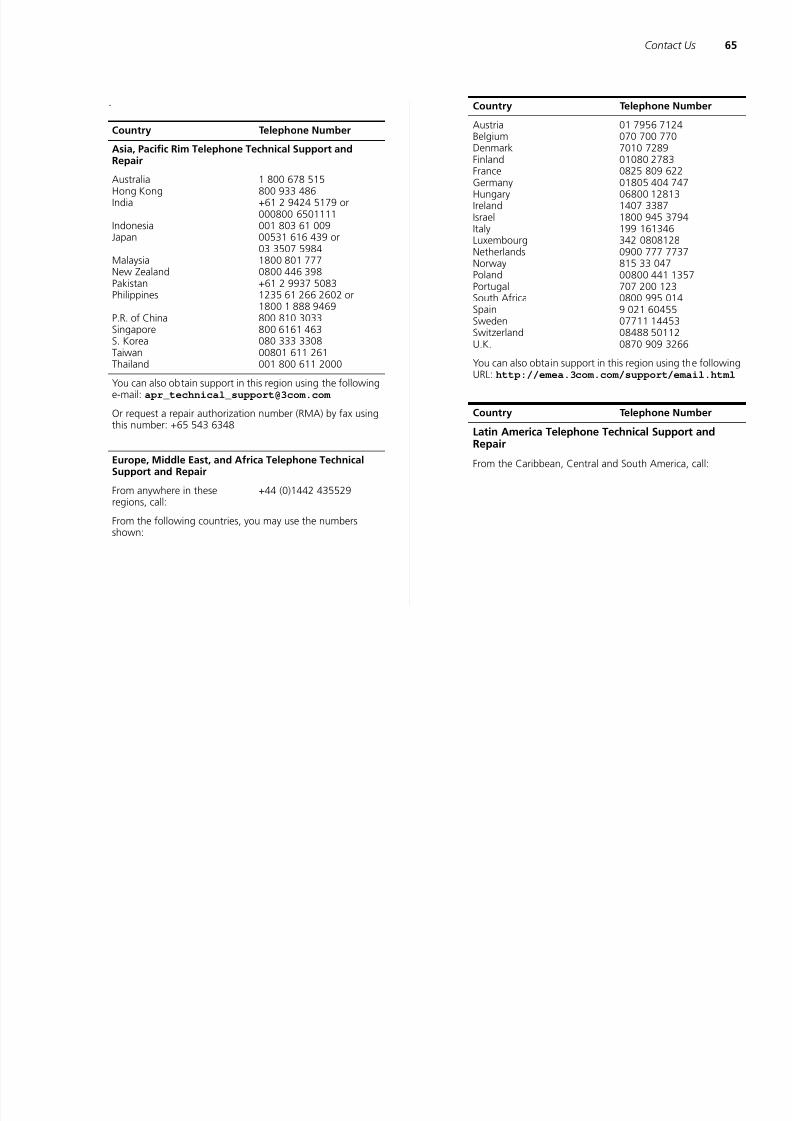
Country Telephone NumberAsia, Pacific Rim Telephone Technical Support andRepair
AustraliaHong KongIndia
IndonesiaJapan
MalaysiaNew ZealandPakistanPhilippines
P.R. of ChinaSingaporeS. KoreaTaiwan
Thailand
1 800 678 515800 933 486+61 2 9424 5179 or000800 6501111001 803 61 00900531 616 439 or
03 3507 59841800 801 7770800 446 398+61 2 9937 50831235 61 266 2602 or1800 1 888 9469800 810 3033800 6161 463080 333 330800801 611 261
001 800 611 2000
You can also obtain support in this region using the followinge-mail: [email protected]
Or request a repair authorization number (RMA) by fax usingthis number: +65 543 6348
Europe, Middle East, and Africa Telephone TechnicalSupport and Repair
From anywhere in theseregions, call:
+44 (0)1442 435529
From the following countries, you may use the numbersshown:
Austria
BelgiumDenmarkFinlandFranceGermanyHungaryIrelandIsraelItalyLuxembourgNetherlandsNorwayPolandPortugalSouth AfricaSpainSwedenSwitzerlandU.K.
01 7956 7124
070 700 7707010 728901080 27830825 809 62201805 404 74706800 128131407 33871800 945 3794199 161346342 08081280900 777 7737815 33 04700800 441 1357707 200 1230800 995 0149 021 6045507711 1445308488 501120870 909 3266
You can also obtain support in this region using the followingURL: http://emea.3com.com/support/email.html
Country Telephone Number
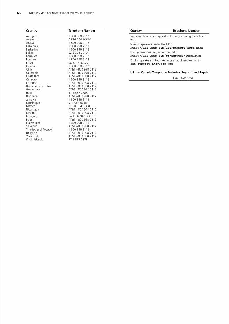
Latin America Telephone Technical Support andRepair
From the Caribbean, Central and South America, call:
Country Telephone Number
66 APPENDIX A: OBTAINING SUPPORT FOR YOUR PRODUCT
Country Telephone Number Country Telephone Number
7/28/2019 3com Manual Switch
http://slidepdf.com/reader/full/3com-manual-switch 66/79
Antigua
ArgentinaArubaBahamasBarbadosBelizeBermudaBonaireBrazilCaymanChile
ColombiaCosta RicaCuracaoEcuadorDominican RepublicGuatemalaHaitiHondurasJamaicaMartiniqueMexicoNicaraguaPanamaParaguayPeruPuerto RicoSalvadorTrinidad and TobagoUruguayVenezuelaVirgin Islands
1 800 988 2112
0 810 444 3COM1 800 998 21121 800 998 21121 800 998 211252 5 201 00101 800 998 21121 800 998 21120800 13 3COM1 800 998 2112AT&T +800 998 2112
AT&T +800 998 2112AT&T +800 998 21121 800 998 2112AT&T +800 998 2112AT&T +800 998 2112AT&T +800 998 211257 1 657 0888AT&T +800 998 21121 800 998 2112571 657 088801 800 849CAREAT&T +800 998 2112AT&T +800 998 211254 11 4894 1888AT&T +800 998 21121 800 998 2112AT&T +800 998 21121 800 998 2112AT&T +800 998 2112AT&T +800 998 211257 1 657 0888
Country Telephone Number
You can also obtain support in this region using the follow-
ing:
Spanish speakers, enter the URL:http://lat.3com.com/lat/support/form.html
Portuguese speakers, enter the URL:http://lat.3com.com/br/support/form.html
English speakers in Latin America should send e-mail to:[email protected]
US and Canada Telephone Technical Support and Repair
1 800 876 3266
Country Telephone Number
B SAFETY INFORMATION

7/28/2019 3com Manual Switch
http://slidepdf.com/reader/full/3com-manual-switch 67/79
Important Safety Information
Please refer to the safety information found in the 3Com Switch Family Safety and Regulatory Informa-tion manual included with this product.
You can find the 3Com Switch Family Safety and Regulatory Information manual on the productCD-ROM that was included with your switch. You can
also download the safety manual from the 3ComWeb site: www.3Com.com
68 APPENDIX B: SAFETY INFORMATION

7/28/2019 3com Manual Switch
http://slidepdf.com/reader/full/3com-manual-switch 68/79
7/28/2019 3com Manual Switch
http://slidepdf.com/reader/full/3com-manual-switch 69/79
70 APPENDIX C: TECHNICAL INFORMATION

7/28/2019 3com Manual Switch
http://slidepdf.com/reader/full/3com-manual-switch 70/79
GLOSSARY
7/28/2019 3com Manual Switch
http://slidepdf.com/reader/full/3com-manual-switch 71/79
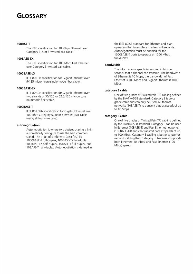
10BASE-T
The IEEE specification for 10 Mbps Ethernet overCategory 3, 4 or 5 twisted pair cable.
100BASE-TX
The IEEE specification for 100 Mbps Fast Ethernetover Category 5 twisted-pair cable.
1000BASE-LX
IEEE 802.3z specification for Gigabit Ethernet over9/125 micron core single-mode fiber cable.
1000BASE-SXIEEE 802.3z specification for Gigabit Ethernet overtwo strands of 50/125 or 62.5/125 micron coremultimode fiber cable.
1000BASE-T
IEEE 802.3ab specification for Gigabit Ethernet over100-ohm Category 5, 5e or 6 twisted-pair cable
(using all four wire pairs).
autonegotiation
Autonegotiation is where two devices sharing a link,automatically configure to use the best commonspeed. The order of preference (best first) is:1000BASE-T full-duplex, 100BASE-TX full-duplex,100BASE-TX half-duplex, 10BASE-T full-duplex, and10BASE-T half-duplex. Autonegotiation is defined in
the IEEE 802.3 standard for Ethernet and is anoperation that takes place in a few milliseconds.Autonegotiation must be enabled for the1000BASE-T ports to operate at 1000 Mbps,full-duplex.
bandwidth
The information capacity (measured in bits persecond) that a channel can transmit. The bandwidthof Ethernet is 10 Mbps, the bandwidth of FastEthernet is 100 Mbps and Gigabit Ethernet is 1000Mbps.
category 3 cable
One of five grades of Twisted Pair (TP) cabling definedby the EIA/TIA-568 standard. Category 3 is voicegrade cable and can only be used in Ethernetnetworks (10BASE-T) to transmit data at speeds of upto 10 Mbps.
category 5 cableOne of five grades of Twisted Pair (TP) cabling definedby the EIA/TIA-568 standard. Category 5 can be usedin Ethernet (10BASE-T) and Fast Ethernet networks(100BASE-TX) and can transmit data at speeds of upto 100 Mbps. Category 5 cabling is better to use fornetwork cabling than Category 3, because it supportsboth Ethernet (10 Mbps) and Fast Ethernet (100
Mbps) speeds.
72 GLOSSARY
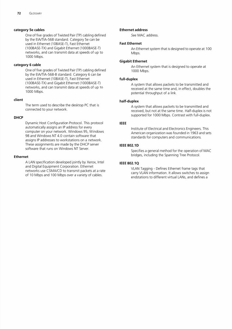
category 5e cables
O f fi d f T i d P i (TP) bli d fi d
Ethernet address
S MAC dd
7/28/2019 3com Manual Switch
http://slidepdf.com/reader/full/3com-manual-switch 72/79
One of five grades of Twisted Pair (TP) cabling defined
by the EIA/TIA-568 standard. Category 5e can beused in Ethernet (10BASE-T), Fast Ethernet(100BASE-TX) and Gigabit Ethernet (1000BASE-T)networks, and can transmit data at speeds of up to1000 Mbps.
category 6 cable
One of five grades of Twisted Pair (TP) cabling defined
by the EIA/TIA-568-B standard. Category 6 can beused in Ethernet (10BASE-T), Fast Ethernet(100BASE-TX) and Gigabit Ethernet (1000BASE-T)networks, and can transmit data at speeds of up to1000 Mbps.
client
The term used to describe the desktop PC that isconnected to your network.
DHCP
Dynamic Host Configuration Protocol. This protocolautomatically assigns an IP address for everycomputer on your network. Windows 95, Windows98 and Windows NT 4.0 contain software that
assigns IP addresses to workstations on a network.These assignments are made by the DHCP serversoftware that runs on Windows NT Server.
Ethernet
A LAN specification developed jointly by Xerox, Inteland Digital Equipment Corporation. Ethernetnetworks use CSMA/CD to transmit packets at a rate
of 10 Mbps and 100 Mbps over a variety of cables.
See MAC address.
Fast Ethernet
An Ethernet system that is designed to operate at 100Mbps.
Gigabit Ethernet
An Ethernet system that is designed to operate at1000 Mbps.
full-duplex
A system that allows packets to be transmitted andreceived at the same time and, in effect, doubles thepotential throughput of a link.
half-duplex
A system that allows packets to be transmitted andreceived, but not at the same time. Half-duplex is notsupported for 1000 Mbps. Contrast with full-duplex.
IEEE
Institute of Electrical and Electronics Engineers. ThisAmerican organization was founded in 1963 and setsstandards for computers and communications.
IEEE 802.1D
Specifies a general method for the operation of MACbridges, including the Spanning Tree Protocol.
IEEE 802.1Q
VLAN Tagging - Defines Ethernet frame tags thatcarry VLAN information. It allows switches to assignendstations to different virtual LANs, and defines a
GLOSSARY 73
standard way for VLANs to communicate acrossswitched networks
IP Address
I t t P t l Add A i id tifi f
7/28/2019 3com Manual Switch
http://slidepdf.com/reader/full/3com-manual-switch 73/79
switched networks.
IEEE 802.1p
An IEEE standard for providing quality of service (QoS)in Ethernet networks. The standard uses packet tagsthat define up to eight traffic classes and allowsswitches to transmit packets based on the taggedpriority value.
IEEE 802.3adA standard that defines link aggregation. 802.3ad isnow incorporated into the relevant sections of theIEEE Std. 802.3-2002.
IETF
Internet Engineering Task Force. An organizationresponsible for providing engineering solutions forTCP/IP networks. In the network management area,this group is responsible for the development of theSNMP protocol.
IP
Internet Protocol. IP is a layer 3 network protocol thatis the standard for sending data through a network.
IP is part of the TCP/IP set of protocols that describethe routing of packets to addressed devices. An IPaddress consists of 32 bits divided into two or threefields: a network number and a host number or anetwork number, a subnet number, and a hostnumber.
Internet Protocol Address. A unique identifier for a
device attached to a network using TCP/IP. Theaddress is written as four octets separated withperiods (full-stops), and is made up of a networksection, an optional subnet section and a hostsection.
LAN
Local Area Network. A network of end stations (such
as PCs, printers, servers) and network devices (hubsand switches) that cover a relatively small geographicarea (usually not larger than a floor or building). LANsare characterized by high transmission speeds overshort distances (up to 1000 meters).
Layer 2
Data Link layer in the ISO 7-Layer DataCommunications Protocol. This is related directly tothe hardware interface for the network devices andpasses on traffic based on MAC addresses.
link aggregation
See Trunking.
MACMedia Access Control. A protocol specified by theIEEE for determining which devices have access to anetwork at any one time.
MAC address
Media Access Control Address. Also called thehardware, physical, or Ethernet address. A layer 2
address associated with a particular network device.
74 GLOSSARY
Most devices that connect to a LAN have a MACaddress assigned to them as they are used to identify
SFP
Small Form Factor Pluggable (SFP) Connectors are

7/28/2019 3com Manual Switch
http://slidepdf.com/reader/full/3com-manual-switch 74/79
address assigned to them as they are used to identify
other devices on a network. MAC addresses are 6bytes long.
network
A network is a collection of computers and othercomputer equipment that are connected for thepurpose of exchanging information or sharingresources. Networks vary in size, some are within a
single room, others span continents.
ping
Packet Internet Groper. An internet utility used todetermine whether a particular IP address is online. Itis used to test and debug a network by sending out apacket and waiting for a response.
protocolA set of rules for communication between devices ona network. The rules dictate format, timing,sequencing and error control.
RJ-45
A standard connector used to connect Ethernet
networks. The “RJ” stands for “registered jack.”server
A computer on a network that is shared by multipleend stations. Servers provide end stations with accessto shared network services such as computer files andprinter queues.
Small Form Factor Pluggable (SFP) Connectors are
based on an open standard that enables hotswapping of various types of fiber optic andcopper-based transceivers into the host equipment.
subnet address
An extension of the IP addressing scheme that allowsa site to use a single IP network address for multiplephysical networks.
subnet mask
A subnet mask, which may be a part of the TCP/IPinformation provided by your ISP, is a set of fournumbers configured like an IP address. It is used tocreate IP address numbers used only within aparticular network (as opposed to valid IP addressnumbers recognized by the Internet, which mustassigned by InterNIC).
subnet
A network that is a component of a larger network.
switch
A device that interconnects several LANs to form a
single logical LAN that comprises of several LANsegments. Switches are similar to bridges, in that theyconnect LANs of a different type; however theyconnect more LANs than a bridge and are generallymore sophisticated.
TCP/IP
Transmission Control Protocol/Internet Protocol. This
is the name for two of the most well-known protocols
GLOSSARY 75
developed for the interconnection of networks.Originally a UNIX standard, TCP/IP is now supported
7/28/2019 3com Manual Switch
http://slidepdf.com/reader/full/3com-manual-switch 75/79
g y , pp
on almost all platforms, and is the protocol of theInternet.
TCP relates to the content of the data travellingthrough a network — ensuring that the informationsent arrives in one piece when it reaches itsdestination. IP relates to the address of the endstation to which data is being sent, as well as the
address of the destination network.
traffic monitoring
Enables the monitoring of port traffic by attaching anetwork analyzer to one switch port, in order tomonitor the traffic of other ports on the Switch.
trunking
A method which specifies how to create a singlehigh-speed logical link that combines severallower-speed physical links.
VLAN
Virtual LAN. A collection of network nodes that sharethe same collision domain regardless of their physicallocation or connection point in the network. A VLANserves as a logical workgroup with no physicalbarriers, and allows users to share information andresources as though located on the same LAN.

7/28/2019 3com Manual Switch
http://slidepdf.com/reader/full/3com-manual-switch 76/79
INDEX

7/28/2019 3com Manual Switch
http://slidepdf.com/reader/full/3com-manual-switch 77/79
Numbers1000BASE-LX 711000BASE-SX 711000BASE-T 71100BASE-TX 71
10BASE-T 71
Aauto IP configuration 29
default IP address 29default mask 29
autonegotiation 7autosensing 7
Bbandwidth 71
Cclient 72configuration
overview 27connecting
network device 17SFP transceivers 18
conventionsnotice icons, About This Guide 5text, About This Guide 5
DDHCP 72Discovery 21
dynamic host control protocol See DHCP
EEthernet 72
F
Fast Ethernet 72forgotten IP address 59forgotten password 59free-standing 14front panel
Link/Activity LEDs 10Module Active LEDs 11Power LED 12RJ-45 ports 11self-adhesive pads 12
SFP ports 10full-duplex 72
GGigabit Ethernet 72
Hhalf-duplex 72
IIEEE 72IETF 73install ing 13IP address
auto configuration 29modifying 29
IP defined 73
LLAN defined 73LED issues 60LEDs
Link/Activity 10
Module Active 11Power 12link aggregation 45local area network 73
MMAC address 73media access control 73monitoring traffic 49
mounting kitcontents 13using 14
Nnetwork analyzer 49network cables
category 3 71category 5 71
category 5e 72category 6 72network defined 74
Ppackage contents 12panels
front 9rear 12
password
78 INDEX
changing 32, 34default (blank) 32setting 28
troubleshooting 59forgotten IP address 59forgotten password 59

7/28/2019 3com Manual Switch
http://slidepdf.com/reader/full/3com-manual-switch 78/79
setting 28
physical features 9port settingsconfiguring 43, 50, 53
portsRJ-45 11SFP 8, 10
positioning 13POST 16powering on 16power-on self-test See POST
protocol defined 74
Rrack-mounting 14rear panel
power supply 12Recovery button 12
resetting to factory defaults 59RJ-45
defined 74ports 11
Sserver defined 74SFP ports 8, 10SFP transceivers 18
approved (supported) 18inserting 18
removing 19spot checks 19subnet mask 74switch defined 74
TTCP/IP 73
defined 74traffic 75
monitoring 49
forgotten password 59
LED-related issues 60POST failed 17trunking See link aggregation
Uuser name
default 32
Vviewing
status information 27VLANs 35
creating 41maximum supported 35sample configurations 40
WWeb interface
accessing directly 26accessing using Discovery 21buttons 25connecting 21logging on 23menu 23navigating 23requirements for accessing 21
REGULATORY NOTICES
7/28/2019 3com Manual Switch
http://slidepdf.com/reader/full/3com-manual-switch 79/79
FCC STATEMENTThis equipment has been tested and found to comply with the limits for a Class A digitaldevice, pursuant to part 15 of the FCC rules. These limits are designed to providereasonable protection against harmful interference when the equipment is operated ina commercial environment. This equipment generates, uses and can radiate radiofrequency energy and, if not installed and used in accordance with the instructions, maycause harmful interference to radio communications. Operation of this equipment in aresidential area is likely to cause harmful interference to radio communications, in whichcase the user will be required to correct the interference at their own expense.
INFORMATION TO THE USER
If this equipment does cause interference to radio or television reception, which can bedetermined by turning the equipment off and on, the user is encouraged to try tocorrect the interference by one or more of the following measures:
■ Reorient the receiving antenna.
■ Relocate the equipment with respect to the receiver.
■ Move the equipment away from the receiver.
■ Plug the equipment into a different outlet so that equipment and receiver are ondifferent branch circuits.
If necessary, the user should consult the dealer or an experienced radio/televisiontechnician for additional suggestions. The user may find the following booklet preparedby the Federal Communications Commission helpful:
How to Identify and Resolve Radio-TV Interference Problems
This booklet is available from the U.S. Government Printing Office, Washington,
DC 20402, Stock No. 004-000-00345-4.
In order to meet FCC emissions limits, this equipment must be used only with cableswhich comply with IEEE 802.3.
CE STATEMENT (EUROPE)
This product complies with the European Low Voltage Directive 73/23/EEC and EMCDirective 89/336/EEC as amended by European Directive 93/68/EEC/.
CSA STATEMENT
This Class A digital apparatus meets all requirements of the CanadianInterference-Causing Equipment Regulations.
Cet appareil numérique de la classe A respecte toutes les exigences du Règlement sur lematériel brouilleur du Canada.
VCCI STATEMENT


