23
ECH3906 Comput er Aided Chemical Engineering Section 1: Solid Editing Section 2: Section Plane and Multiview Drawing of 3-D Solid Week 12 – 29 th November 2015
| Date post: | 06-Jul-2018 |
| Category: |
Documents |
| Upload: | putri-saidatina |
| View: | 220 times |
| Download: | 0 times |

8/16/2019 3D AutoCAD Training Materials 2
http://slidepdf.com/reader/full/3d-autocad-training-materials-2 1/24
ECH3906Computer Aided Chemical Engine
Section 1: Solid Editing
Section 2: Section Plane and Multiview Drawing of 3-D Solid
Week 12–
29th
November 2015

8/16/2019 3D AutoCAD Training Materials 2
http://slidepdf.com/reader/full/3d-autocad-training-materials-2 2/24
Learning Outcome To visualize and handle 3-D solid in a 3 dimensional plane (1) choosing
different views such as top, bottom, isometric, etc. (2) rotate, move, copy 3-Dsolid (3) creating 2-D drawing in different plane (XY, YZ, XZ)
To create basic 3-D solid (preloaded solid function) i.e. pyramid, box, cylinder,torus etc.
To create custom 3-D solid using extrude, loft, revolve, and sweep function
Edit and modify 3-D solid using union, subtract, fillet, shell etc.
Create multiple section plane and present drawing properly in a paper
Important: due to time limitation, only basic feature will be taught . The rest you need to explore yourself (need at least 1 year to maste

8/16/2019 3D AutoCAD Training Materials 2
http://slidepdf.com/reader/full/3d-autocad-training-materials-2 3/24
Before Start Training Make sure you are in 3-D Modelling Interface not in Drafting and Annotation
Move your command line to the bottom of the interface and expand your command line. Uncheck u
Make sure default view is SW Isometric. If not, Move Cursor to Top Left of your drawing sheet >Select SW Isometric
Now you are ready for 3-D AutoCAD training
Important: default view for 3-D drawing is SW Isometric. View Control can be changed depending on situation and suit

8/16/2019 3D AutoCAD Training Materials 2
http://slidepdf.com/reader/full/3d-autocad-training-materials-2 4/24
SECTION 1Solid Editing
8/16/2019 3D AutoCAD Training Materials 2
http://slidepdf.com/reader/full/3d-autocad-training-materials-2 5/24
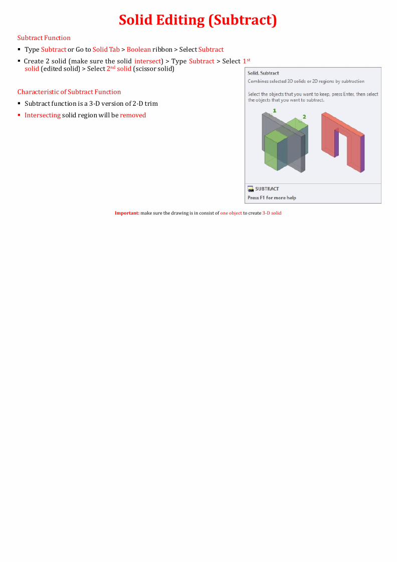
Solid Editing (Subtract)Subtract Function
Type Subtract or Go to Solid Tab > Boolean ribbon > Select Subtract
Create 2 solid (make sure the solid intersect ) > Type Subtract > Select 1st
solid (edited solid) > Select 2nd solid (scissor solid)
Characteristic of Subtract Function
Subtract function is a 3-D version of 2-D trim
Intersecting solid region will be removed
Important: make sure the drawing is in consist of one object to create 3-D solid

8/16/2019 3D AutoCAD Training Materials 2
http://slidepdf.com/reader/full/3d-autocad-training-materials-2 6/24
Training (Section 1 - 1) Design intention (1) – Create solid below using extrude and subtract function
Important: make sure to JOIN your 2-D drawing
Extrude length = 56
R17R11
35
8 1717
5 15110
12

8/16/2019 3D AutoCAD Training Materials 2
http://slidepdf.com/reader/full/3d-autocad-training-materials-2 7/24
Solid Editing (Union)Union Function
Type Union or Go to Solid Tab > Boolean ribbon > Select Union
Create 2 solid (make sure the solid intersect ) > Type Union > Select solid
Characteristic of Union Function
Union function is a 3-D version of 2-D join
Selected solid will be combined into one solid
Important: make sure the drawing is in consist of one object to create 3-D solid
8/16/2019 3D AutoCAD Training Materials 2
http://slidepdf.com/reader/full/3d-autocad-training-materials-2 8/24
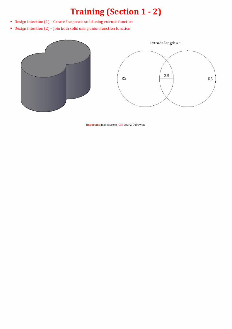
Training (Section 1 - 2) Design intention (1) – Create 2 separate solid using extrude function
Design intention (2) – Join both solid using union function function
Important: make sure to JOIN your 2-D drawing
Extrude length = 5
R5 2.5

8/16/2019 3D AutoCAD Training Materials 2
http://slidepdf.com/reader/full/3d-autocad-training-materials-2 9/24
Solid Editing (Shell)Shell Function
Type Solidedit > Type B > Type S or Go to Solid Tab > Solid Editing ribbon > Select Shell
Characteristic of Shell Function
Shell function is used to create hollow object with a specified thickness
The user need to remove one or many faces/surface depending on need
Important: make sure the drawing is in consist of one object to create 3-D solid
8/16/2019 3D AutoCAD Training Materials 2
http://slidepdf.com/reader/full/3d-autocad-training-materials-2 10/24
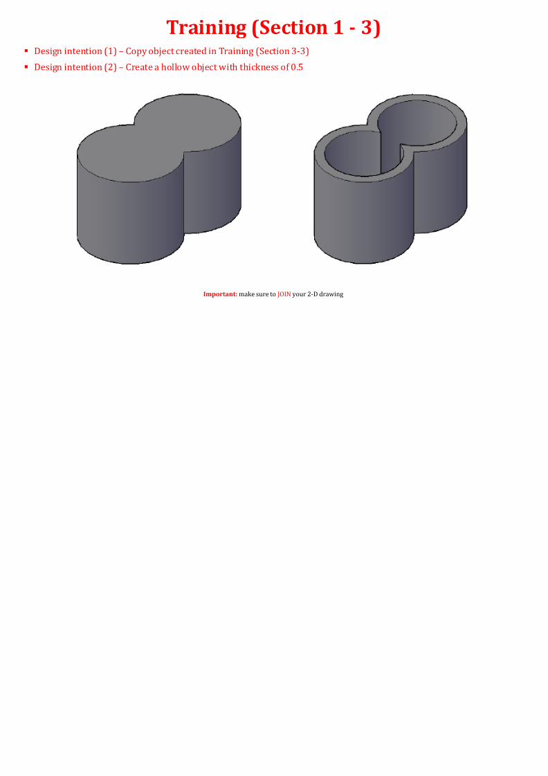
Training (Section 1 - 3) Design intention (1) – Copy object created in Training (Section 3-3)
Design intention (2) – Create a hollow object with thickness of 0.5
Important: make sure to JOIN your 2-D drawing

8/16/2019 3D AutoCAD Training Materials 2
http://slidepdf.com/reader/full/3d-autocad-training-materials-2 11/24
Solid Editing (Fillet Edge)Shell Function
Type Filletedge or Go to Solid Tab > Solid Editing ribbon > Select Fillet Edge
Characteristic of Fillet Edge Function
Fillet Edge function is a 3-D version of 2-D fillet
The user need specify fillet radius
Important: make sure the drawing is in consist of one object to create 3-D solid
8/16/2019 3D AutoCAD Training Materials 2
http://slidepdf.com/reader/full/3d-autocad-training-materials-2 12/24
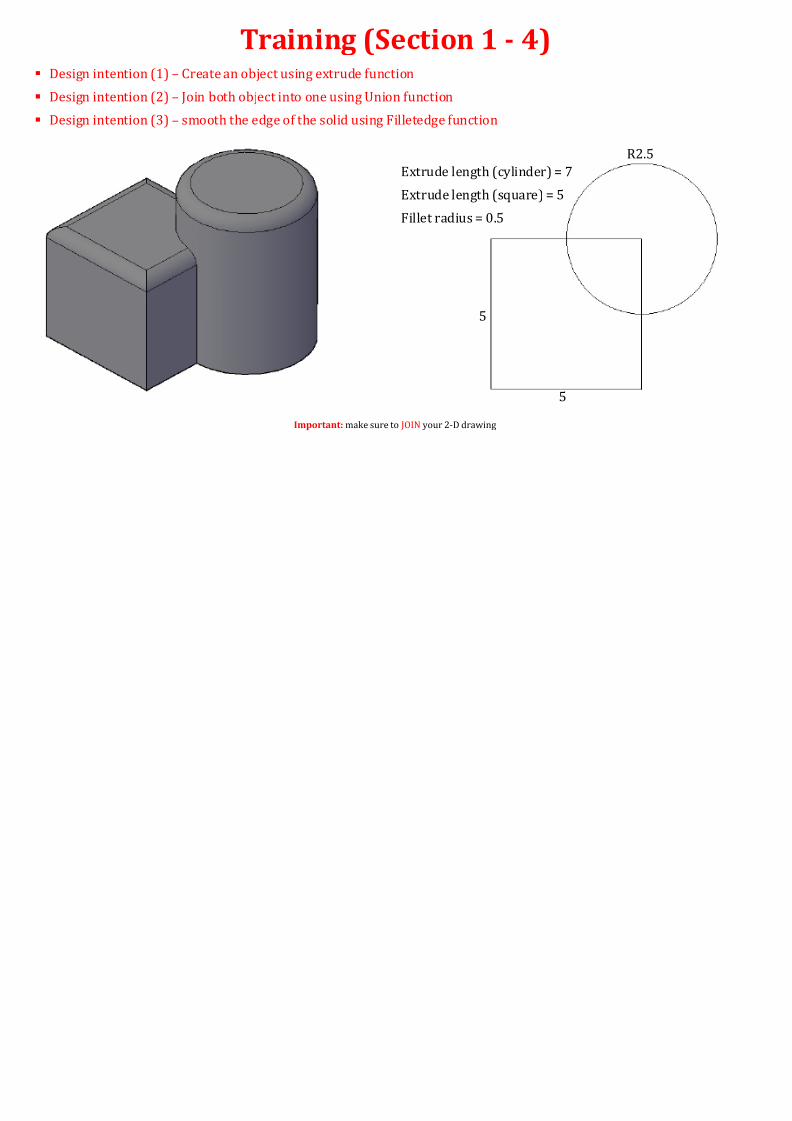
Training (Section 1 - 4) Design intention (1) – Create an object using extrude function
Design intention (2) – Join both object into one using Union function
Design intention (3) – smooth the edge of the solid using Filletedge function
Important: make sure to JOIN your 2-D drawing
5
R
5
Extrude length (cylinder) = 7
Extrude length (square) = 5
Fillet radius = 0.5

8/16/2019 3D AutoCAD Training Materials 2
http://slidepdf.com/reader/full/3d-autocad-training-materials-2 13/24
B
C
Fillet (small) – R0.5
Fillet (big)–
R1.5
Chamfer distance (1st - 0.
Create C using mirror fun
Sphere dimension = R2.5
No of item = 10
New Command: LAYER
Convert to diagram B
Training (Overall – Ball Bearing) Design intention (1) – Create an object shown below
Important: make sure to JOIN your 2-D drawing
10
1
A
2
2
84
2
10
15
15
8/16/2019 3D AutoCAD Training Materials 2
http://slidepdf.com/reader/full/3d-autocad-training-materials-2 14/24
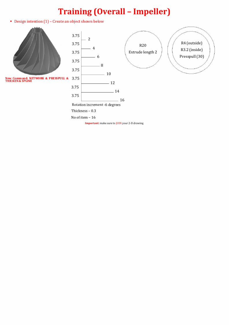
Training (Overall – Impeller) Design intention (1) – Create an object shown below
Important: make sure to JOIN your 2-D drawing
New Command: NETWORK & PRESSPULL &
THICKEN & SPLINE
3.75
3.75
3.75
3.75
3.75
3.75
3.75
3.75
2
4
6
8
10
12
14
16
Rotation increment -6 degrees
Thickness – 0.3
No of item – 16
R20
Extrude length 2
R
R
P
8/16/2019 3D AutoCAD Training Materials 2
http://slidepdf.com/reader/full/3d-autocad-training-materials-2 15/24
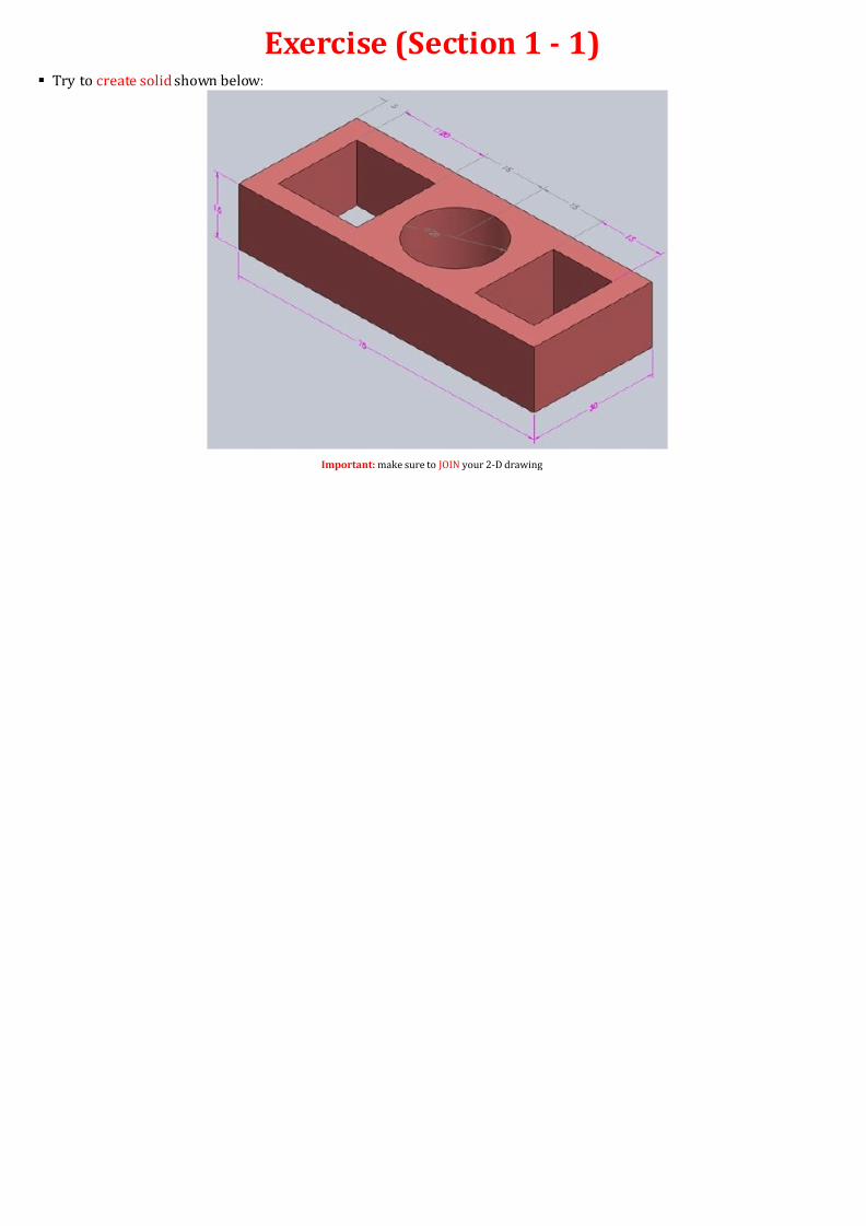
Exercise (Section 1 - 1) Try to create solid shown below:
Important: make sure to JOIN your 2-D drawing
8/16/2019 3D AutoCAD Training Materials 2
http://slidepdf.com/reader/full/3d-autocad-training-materials-2 16/24
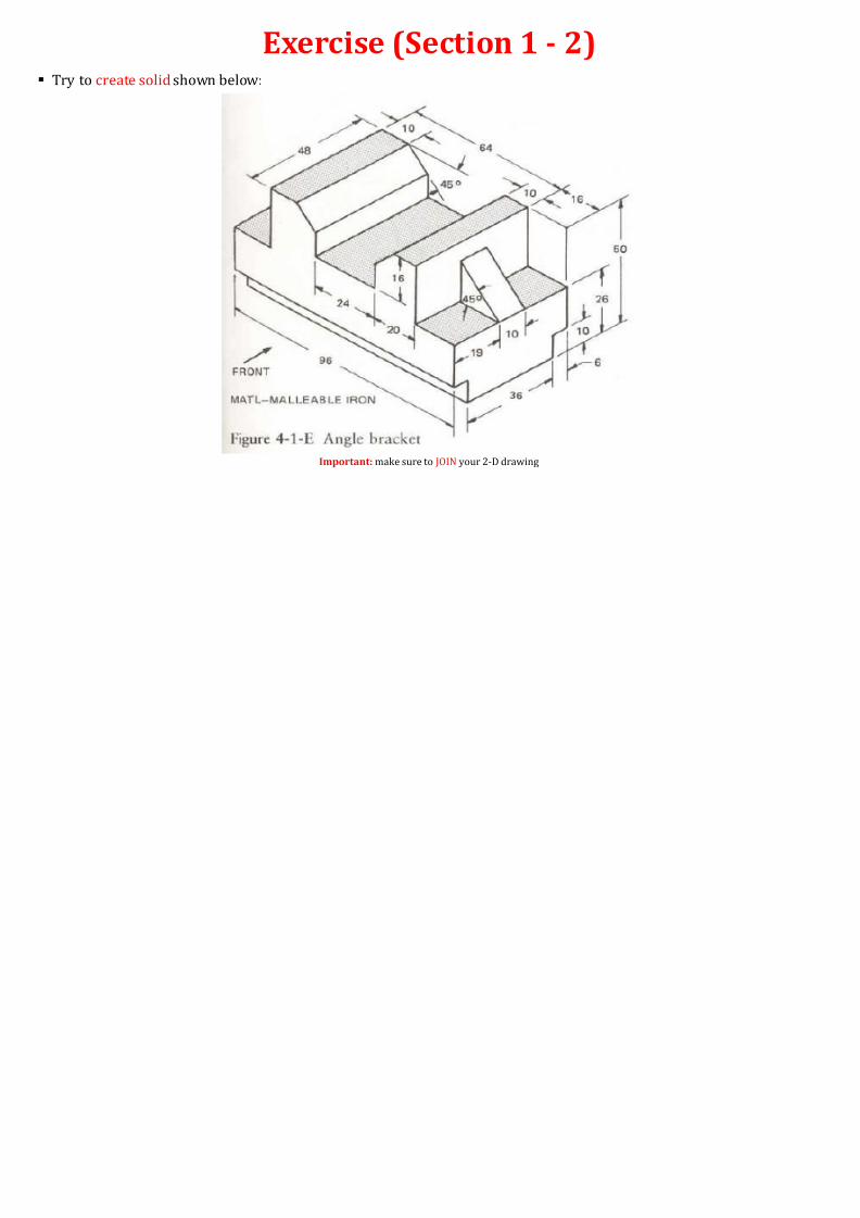
Exercise (Section 1 - 2) Try to create solid shown below:
Important: make sure to JOIN your 2-D drawing

8/16/2019 3D AutoCAD Training Materials 2
http://slidepdf.com/reader/full/3d-autocad-training-materials-2 17/24
SECTION 2Section Plane and Multiview Drawing
Solid
8/16/2019 3D AutoCAD Training Materials 2
http://slidepdf.com/reader/full/3d-autocad-training-materials-2 18/24
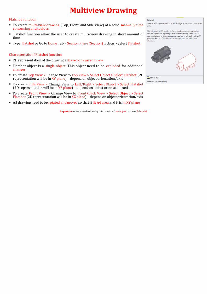
Multiview DrawingFlatshot Function
To create multi-view drawing (Top, Front, and Side View) of a solid manually timeconsuming and tedious.
Flatshot function allow the user to create multi-view drawing in short amount of
time
Type Flatshot or Go to Home Tab > Section Plane (Section) ribbon > Select Flatshot
Characteristic of Flatshot function
2D representation of the drawing is based on current view.
Flatshot object is a single object . This object need to be exploded for additionalchanges
To create Top View > Change View to Top View > Select Object > Select Flatshot (2Drepresentation will be in XY plane) – depend on object orientation/axis
To create Side View > Change View to Left/Right > Select Object > Select Flatshot (2D representation will be in YZ plane) – depend on object orientation/axis
To create Front View > Change View to Front/Back View > Select Object > Select Flatshot (2D representation will be in XZ plane) – depend on object orientation/axis
All drawing need to be rotated and moved so that it fit A4 area and it is in XY plane
Important: make sure the drawing is in consist of one object to create 3-D solid

8/16/2019 3D AutoCAD Training Materials 2
http://slidepdf.com/reader/full/3d-autocad-training-materials-2 19/24
Training (Section 2 - 1) Design intention (1) – Create solid below using extrude and subtract function
Design intention (2) – generate multiview drawing (TOP, FRONT, SIDE) of the object in XY plane u(Useful command3DROTATE, 3DMOVE)
Important: make sure to JOIN your 2-D drawing
Center
1.5
6
68 degree angle
14
14
0.5
R1
R2
8/16/2019 3D AutoCAD Training Materials 2
http://slidepdf.com/reader/full/3d-autocad-training-materials-2 20/24
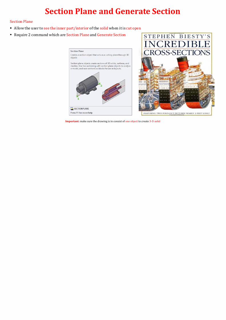
Section Plane and Generate SectionSection Plane
Allow the user to see the inner part/interior of the solid when it is cut open
Require 2 command which are Section Plane and Generate Section
Important: make sure the drawing is in consist of one object to create 3-D solid
8/16/2019 3D AutoCAD Training Materials 2
http://slidepdf.com/reader/full/3d-autocad-training-materials-2 21/24
Section Plane and Generate Section
Important: make sure the drawing is in consist of one object to create 3-D solid
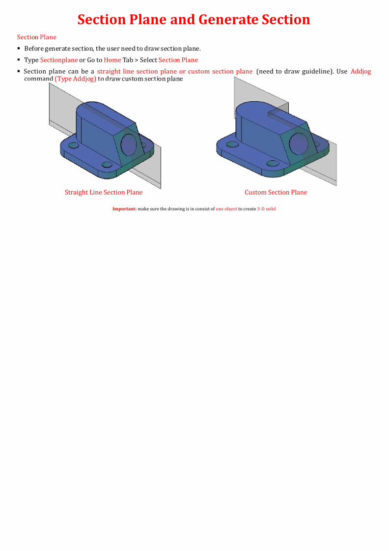
Straight Line Section Plane Custom Section Plane
Section Plane
Before generate section, the user need to draw section plane.
Type Sectionplane or Go to Home Tab > Select Section Plane
Section plane can be a straight line section plane or custom section plane (need to draw gucommand (Type Addjog) to draw custom section plane

8/16/2019 3D AutoCAD Training Materials 2
http://slidepdf.com/reader/full/3d-autocad-training-materials-2 22/24
Section Plane and Generate Section (TrainiGenerate Section
The user can generate section only after section plane is drawn.
Generated section can be 2D or 3D
Type Generatesection > select type of section (2D or 3D) > Select Section Plane
HATCH command is useful to change the closed area fill
Important: make sure the drawing is in consist of one object to create 3-D solid
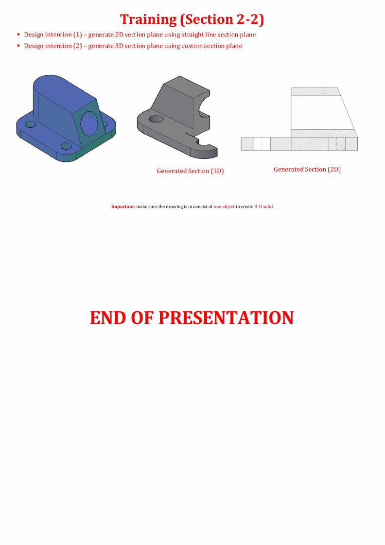
Generated Section (3D) Generated Sec
8/16/2019 3D AutoCAD Training Materials 2
http://slidepdf.com/reader/full/3d-autocad-training-materials-2 23/24
Training (Section 2-2) Design intention (1) – generate 2D section plane using straight line section plane
Design intention (2) – generate 3D section plane using custom section plane
Important: make sure the drawing is in consist of one object to create 3-D solid
Generated Section (3D) Generated S

8/16/2019 3D AutoCAD Training Materials 2
http://slidepdf.com/reader/full/3d-autocad-training-materials-2 24/24
END OF PRESENTATION


